MARATHON 21000(R) Multi Purpose Centrifuge Operation...
41
MARATHON 21000(R) Multi Purpose Centrifuge Operation Manual Model 21000 1L Ventilated Centrifuge Cat. No. 04-977-21000 -- 120 VAC, 60 Hz Cat. No. 04-977-210001 -- 220, 230, 240 VAC, 50/60 Hz Model 21000R 1L Refrigerated Centrifuge Cat. No. 04-977-21000R -- 120 VAC, 60 Hz Cat. No. 04-977-21001R -- 220, 230, 240 VAC, 50 Hz Cat. No. 04-977-21002R -- 230 VAC, 60 Hz Part No. 04 - 977 - 21000M Rev. 4 2000 Park Lane Pittsburgh, PA 15275 Tel. (800) 766-7000 Fax (800) 926-1166
Transcript of MARATHON 21000(R) Multi Purpose Centrifuge Operation...
MARATHON 21000(R) Multi Purpose Centrifuge
Operation Manual
Model 21000 1L Ventilated Centrifuge Cat. No. 04-977-21000 -- 120 VAC, 60 Hz Cat. No. 04-977-210001 -- 220, 230, 240 VAC, 50/60 Hz
Model 21000R 1L Refrigerated Centrifuge Cat. No. 04-977-21000R -- 120 VAC, 60 Hz Cat. No. 04-977-21001R -- 220, 230, 240 VAC, 50 Hz Cat. No. 04-977-21002R -- 230 VAC, 60 Hz
Part No. 04-977-21000M Rev. 4
2000 Park Lane Pittsburgh, PA 15275 Tel. (800) 766-7000 Fax (800) 926-1166
MARATHON Series Operation Manual 2
Table of Contents
1 INTRODUCTION 4
1.1 GENERAL PRODUCT DESCRIPTION ......................................................................................... 4 1.2 ABOUT THIS MANUAL............................................................................................................ 5 1.3 WARNINGS, CAUTIONS, AND NOTES ...................................................................................... 6
2 INSTALLATION 7
2.1 RECEIVING THE UNIT ............................................................................................................. 7 2.2 SITE PREPARATION................................................................................................................. 7 2.3 POWER CONFIGURATION........................................................................................................ 9 2.4 MOVING THE UNIT ............................................................................................................... 10 2.5 THE FRONT PANEL ............................................................................................................... 11
3 OPERATION 15
3.1 ROTOR AND ACCESSORIES ................................................................................................... 15 3.2 STARTING AND STOPPING A RUN ......................................................................................... 18 3.3 STORED PROGRAMS.............................................................................................................. 19 3.4 ROTOR RECOGNITION SYSTEM............................................................................................. 21 3.5 REFRIGERATION (21000R ONLY) ......................................................................................... 22 3.6 DIAGNOSTIC MESSAGES AND ERROR CODES....................................................................... 23
4 APPLICATIONS 25
4.1 INTRODUCTION..................................................................................................................... 25 4.2 SPEED AND FORCE TABLES .................................................................................................. 27 4.3 DERATING TABLES ............................................................................................................... 30 4.4 CHEMICAL RESISTANCE TABLE ........................................................................................... 32 4.5 DECONTAMINATION TABLE ................................................................................................. 33 4.6 RCF NOMOGRAPH ................................................................................................................ 34
5 MAINTENANCE 35
5.1 INTRODUCTION..................................................................................................................... 35 5.2 CARE AND CLEANING........................................................................................................... 35 5.3 COVER INTERLOCK BYPASS ................................................................................................. 38 5.4 FUSES NOT REPLACEABLE BY OPERATOR............................................................................. 38 5.5 CONDITION OF RETURNED EQUIPMENT ............................................................................... 39 5.6 WARRANTY .......................................................................................................................... 39
6 SPECIFICATIONS 40

MARATHON Series Operation Manual 3
Copyright ©, 1998
Fisher Scientific
Printed in the USA
MARATHON Series Operation Manual 4
1 Introduction
1.1 General Product Description
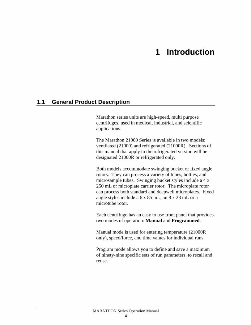
Marathon series units are high-speed, multi purpose centrifuges, used in medical, industrial, and scientific applications.
The Marathon 21000 Series is available in two models: ventilated (21000) and refrigerated (21000R). Sections of this manual that apply to the refrigerated version will be designated 21000R or refrigerated only.
Both models accommodate swinging bucket or fixed angle rotors. They can process a variety of tubes, bottles, and microsample tubes. Swinging bucket styles include a 4 x 250 mL or microplate carrier rotor. The microplate rotor can process both standard and deepwell microplates. Fixed angle styles include a 6 x 85 mL, an 8 x 28 mL or a microtube rotor.
Each centrifuge has an easy to use front panel that provides two modes of operation: Manual and Programmed.
Manual mode is used for entering temperature (21000R only), speed/force, and time values for individual runs.
Program mode allows you to define and save a maximum of ninety-nine specific sets of run parameters, to recall and reuse.

MARATHON Series Operation Manual 5
The Marathon Series features a maintenance-free, brushless motor, and an easy-to-use front panel, which provides three versatile timing modes: automatic timed run, short spin (momentary), and hold (continuous mode). Acceleration and brake rates may be controlled, to optimize runs: rapid for fast separations or slow for delicate samples. Repeat runs, with the same speed and time settings, may be achieved at the touch of a key.
A fail-safe cover interlock insures that the cover is closed, before a run can begin, and keeps the cover closed, until the rotor has reached a safe low speed (below 100 rpm), even in the event of a power failure.
The rugged steel cabinet and rigid construction provide quiet operation and long term reliability.
1.2 About This Manual
The Operations Manual contains all of the information needed to install, operate, and maintain a Marathon Series centrifuge. Refrigerated and ventilated models operate similarly, and any differences are highlighted and noted, throughout this manual. This manual, also, contains speed and force, derating, chemical resistance, and decontamination tables. The last chapter lists the units specifications.
This manual is written for centrifuge operators. In addition to operation information, it contains a few basic troubleshooting techniques, and a chapter on maintenance. This Operation Manual is not a guide for servicing centrifuge units.
MARATHON Series Operation Manual 6
1.3 Warnings, Cautions, and Notes
The terms warning, caution, and note have specific meanings in this manual.
A Warning advises against certain actions or situations that could result in personal injury.
A Caution advises against actions or situations that could damage equipment, produce inaccurate data, or invalidate a procedure.
A Note provides useful information regarding an operation, function, or procedure.
MARATHON Series Operation Manual 7
2 Installation
2.1 Receiving the Unit
Fisher Scientific ships the centrifuge in a carton that protects it from shipping hazards. Follow the unpacking instructions on the carton. Be sure to complete and return the postage-paid warranty card.
2.2 Site Preparation
The unit normally resides on a bench top. The 21000 (ventilated model) can be placed in a cold room (no colder than 4 C), for processing temperature-sensitive samples. When you remove the centrifuge from a cold environment, do not operate for a minimum of two hours, so that any condensation will evaporate.
Note: When used in a cold room environment, some bearing noise may become evident. The bearing lubricant thickens at low temperatures. As the centrifuge speeds up, it is thinned and distributed more evenly. Once this occurs, any noise should subside.

MARATHON Series Operation Manual 8
The following table lists the physical dimensions for the 21000 and 21000R:
21000R 21000
Sample Loading Height 13.7 (34.8 cm) 13.7 (34.8 cm)
Cover Closed Height 15.5 (39.4 cm) 15.5 (39.4 cm)
Cover Open Height 38.5 (97.8 cm) 38.5 (97.8 cm)
Width 28 (71.1 cm) 20.3 (51.4 cm)
Depth 23.4 (59.4 cm) 23.4 (59.4 cm)
A clearance of 8 cm (3 inches) should be provided on each side of the unit, to ensure proper ventilation. Place the centrifuge on a clean, dry surface, to make certain that the suction feet at the bottom grip the surface firmly. Keep the area beneath the unit free of debris and loose materials.
The resting surface must be level, to ensure quiet, vibration-free operation. A rigid and stable location is important. An improperly loaded centrifuge may vibrate or move.
Warning: International Electrotechnical Commission standard 1010 part 2-20 limits the permitted movement of a laboratory centrifuge to 300 mm (12 in) in the unlikely event of a disruption. Laboratory management procedures should require that no person or any hazardous materials enter within this boundary while the centrifuge operates.
MARATHON Series Operation Manual 9
2.3 Power Configuration
The Marathon Series uses AC power in different configurations, appropriate for use throughout the world. Please check the catalog number of the model that you have purchased, to ensure that the machine you have is the proper power configuration. For best results, the refrigerated centrifuge, 21000R, should be used on a dedicated line. Variations in line voltage or frequency affect the unit s speed and other characteristics. Less than nominal line voltage may prevent the centrifuge from reaching maximum published specifications of speed and/or temperature. Power line voltage, at some locations, may sag, when the refrigeration system turns on.
Power Cord The unit requires a grounded power supply (3 prong outlet). If your facility does not have grounded power outlets, arrange for a proper grounding. The power cord plugs in on the left side of the unit.
Warning: Do not remove the grounding pin from the centrifuge power cord. Do not use the bare wired power cord to attach a power plug that does not have a grounding pin.
The power cord provided with the unit is correctly rated for the highest current demand. This power cord should not be interchanged with cords from equipment with lower current demand. Exchange of power cords between equipment may create a fire hazard.
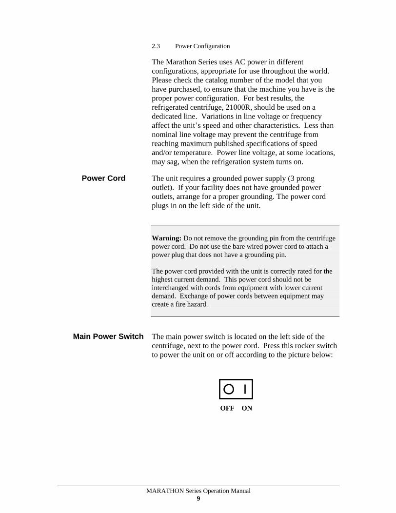
Main Power Switch The main power switch is located on the left side of the centrifuge, next to the power cord. Press this rocker switch to power the unit on or off according to the picture below:
OFF ON
MARATHON Series Operation Manual 10
Circuit Breaker The system provides an automatic circuit breaker, for emergency situations, such as power surges, that could damage the unit.
If the circuit breaker trips: 1. Unplug the unit. 2. Press the white button, on the left side of the unit. 3. Plug the unit back in.
2.4 Moving the Unit
Suction cups, at the bottom of the unit, keep it anchored to the work surface. Keeping the unit stationary is a safety feature.
To move the unit to a new location:
Caution: The unit can weigh up to 222 lb. (101 kg). Use precaution when moving to avoid any injury.
1. Check that the new site meets the criteria in Section 2.2 before moving the unit.
2. Position a flat object, such as a tongue depressor, near a suction cup at the bottom of the unit.
3. Lift up an edge of the cup, and insert the flat object far enough to break the vacuum seal.
4. When all four cups are disengaged, lift the unit from the work surface.
Caution: When the unit is in its new location, ensure that the suction cups adhere correctly to the work surface.

MARATHON Series Operation Manual 11
2.5 The Front Panel
The Front Control Panel (21000R Model Shown)
The control panel contains numeric displays for RPM/RCF (Speed/Force), Time, program, and Temperature (Refrigerated only). These displays have two states or modes: Actual (bright display) and Set (dim display).
In Actual mode (bright display), they indicate current run conditions, such as:
rotor speed or force
elapsed time of, or time remaining in, the run
actual temperature (Refrigerated only)
program number
In Set mode (dim display), the display indicates the desired settings for the run. Set mode is activated when:
SPEED, TIME, TEMP., or PROGRAM are pressed
briefly, at the start of a run
briefly, after the unit is switched ON
The numeric displays can, also, display warning or error messages (see Section 3.5). Descriptions of the displays appear on the following pages.
SPEED Speed Key: Pressing the SPEED key switches the display
MARATHON Series Operation Manual 12
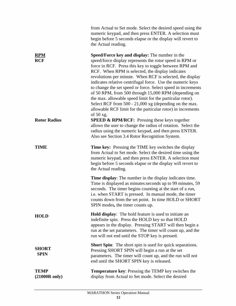
from Actual to Set mode. Select the desired speed using the numeric keypad, and then press ENTER. A selection must begin before 5 seconds elapse or the display will revert to the Actual reading.
RPM
RCF
Speed/Force key and display: The number in the speed/force display represents the rotor speed in RPM or force in RCF. Press this key to toggle between RPM and RCF. When RPM is selected, the display indicates revolutions per minute. When RCF is selected, the display indicates relative centrifugal force. Use the numeric keys to change the set speed or force. Select speed in increments of 50 RPM, from 500 through 15,000 RPM (depending on the max. allowable speed limit for the particular rotor). Select RCF from 500 - 21,000 xg (depending on the max. allowable RCF limit for the particular rotor) in increments of 50 xg.
Rotor Radius SPEED & RPM/RCF: Pressing these keys together allows the user to change the radius of rotation. Select the radius using the numeric keypad, and then press ENTER. Also see Section 3.4 Rotor Recognition System.
TIME
HOLD
SHORT SPIN
Time key: Pressing the TIME key switches the display from Actual to Set mode. Select the desired time using the numeric keypad, and then press ENTER. A selection must begin before 5 seconds elapse or the display will revert to the Actual reading.
Time display: The number in the display indicates time. Time is displayed as minutes:seconds up to 99 minutes, 59 seconds. The timer begins counting at the start of a run, i.e. when START is pressed. In manual mode, the timer counts down from the set point. In time HOLD or SHORT SPIN modes, the timer counts up.
Hold display: The hold feature is used to initiate an indefinite spin. Press the HOLD key so that HOLD appears in the display. Pressing START will then begin a run at the set parameters. The timer will count up, and the run will not end until the STOP key is pressed.
Short Spin: The short spin is used for quick separations. Pressing SHORT SPIN will begin a run at the set parameters. The timer will count up, and the run will not end until the SHORT SPIN key is released.
TEMP (21000R only)
Temperature key: Pressing the TEMP key switches the display from Actual to Set mode. Select the desired
MARATHON Series Operation Manual 13
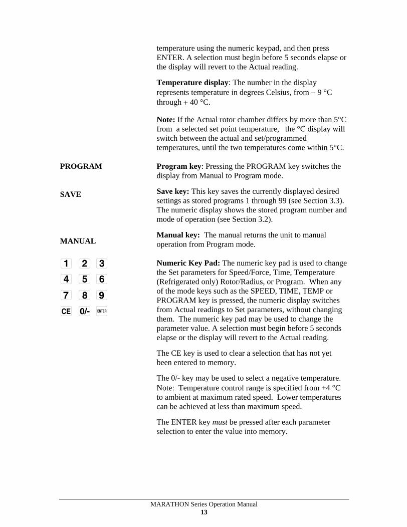
temperature using the numeric keypad, and then press ENTER. A selection must begin before 5 seconds elapse or the display will revert to the Actual reading.
Temperature display: The number in the display represents temperature in degrees Celsius, from 9 C through 40 C.
Note: If the Actual rotor chamber differs by more than 5°C from a selected set point temperature, the °C display will switch between the actual and set/programmed temperatures, until the two temperatures come within 5°C.
PROGRAM
SAVE
MANUAL
Program key: Pressing the PROGRAM key switches the display from Manual to Program mode.
Save key: This key saves the currently displayed desired settings as stored programs 1 through 99 (see Section 3.3). The numeric display shows the stored program number and mode of operation (see Section 3.2).
Manual key: The manual returns the unit to manual operation from Program mode.
Numeric Key Pad: The numeric key pad is used to change the Set parameters for Speed/Force, Time, Temperature (Refrigerated only) Rotor/Radius, or Program. When any of the mode keys such as the SPEED, TIME, TEMP or PROGRAM key is pressed, the numeric display switches from Actual readings to Set parameters, without changing them. The numeric key pad may be used to change the parameter value. A selection must begin before 5 seconds elapse or the display will revert to the Actual reading.
The CE key is used to clear a selection that has not yet been entered to memory.
The 0/- key may be used to select a negative temperature. Note: Temperature control range is specified from +4 C to ambient at maximum rated speed. Lower temperatures can be achieved at less than maximum speed.
The ENTER key must be pressed after each parameter selection to enter the value into memory.
MARATHON Series Operation Manual 14
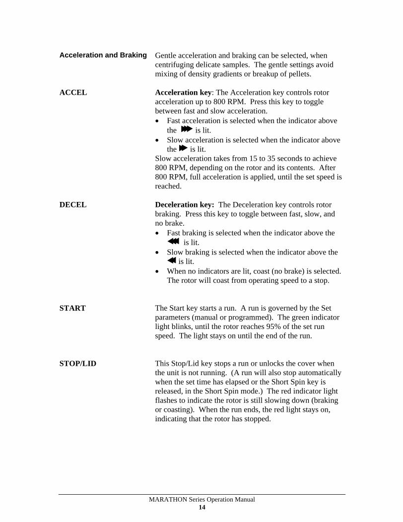
Acceleration and Braking Gentle acceleration and braking can be selected, when centrifuging delicate samples. The gentle settings avoid mixing of density gradients or breakup of pellets.
ACCEL Acceleration key: The Acceleration key controls rotor acceleration up to 800 RPM. Press this key to toggle between fast and slow acceleration.
Fast acceleration is selected when the indicator above the is lit.
Slow acceleration is selected when the indicator above the is lit.
Slow acceleration takes from 15 to 35 seconds to achieve 800 RPM, depending on the rotor and its contents. After 800 RPM, full acceleration is applied, until the set speed is reached.
DECEL Deceleration key: The Deceleration key controls rotor braking. Press this key to toggle between fast, slow, and no brake.
Fast braking is selected when the indicator above the is lit.
Slow braking is selected when the indicator above the is lit.
When no indicators are lit, coast (no brake) is selected. The rotor will coast from operating speed to a stop.
START The Start key starts a run. A run is governed by the Set parameters (manual or programmed). The green indicator light blinks, until the rotor reaches 95% of the set run speed. The light stays on until the end of the run.
STOP/LID This Stop/Lid key stops a run or unlocks the cover when the unit is not running. (A run will also stop automatically when the set time has elapsed or the Short Spin key is released, in the Short Spin mode.) The red indicator light flashes to indicate the rotor is still slowing down (braking or coasting). When the run ends, the red light stays on, indicating that the rotor has stopped.

MARATHON Series Operation Manual 15
3 Operation
3.1 Rotor and Accessories
A balanced load is essential for all centrifuges. An unbalanced load produces vibration, and can damage the unit. A 2 gram load imbalance, at a speed of 4600 RPM, imparts force equivalent to 9.1 kg (20 pounds) at rest. Always ensure that the rotor is loaded symmetrically, with a full complement of accessories, and a full (or paired) set of tubes. Tube adapters should also be installed symmetrically.
The rotors are dynamically balanced at the factory. The manufacturer matches removable parts (trunnion rings, shields, buckets, and carriers) to within 1 gram, and stamps the weight on each piece. Check these markings, whenever you interchange parts, to ensure that opposite parts are matched. Ensure that the total weight of samples and removable parts, loaded in opposing positions, are equal in weight, to within 1 gram. The position numbers, present on many rotors and adapters, identify opposing tube positions.
To obtain good dynamic balance, opposite loads must not only be equal in mass, but must, also, have the same centers of gravity. Opposing containers must be alike in shape, thickness, and distribution of glass or plastic. This is especially important for large containers.
MARATHON Series Operation Manual 16
Tubes loaded into swinging bucket rotors must be symmetric, around the axis of rotation. Verify this by rotating the entire rotor 180°, by hand. The loads should be in the same apparent positions (not mirror images). In addition, the loads within each bucket must, also, be symmetric around the bucket s pivot axis. Verify this by ensuring that each bucket is loaded so that it does not tilt from the vertical, when the rotor is at rest. Maintaining balance within each bucket ensures that the bucket and the tubes swing out to horizontal, when the rotor reaches operating speed, applying centrifugal force toward the bottom of the tubes. Failure to achieve full swing-out causes vibration and premature wear of the rotor and the motor.
Samples of like (similar) specific gravities may be processed in the same run, provided that the samples of the same type are balanced around the rotor, as though they were the only pairs in the rotor.
Caution: Do not exceed maximum rated speed for each rotor/accessory combination. Maximum rated speeds can be found in Section 4.2 - Speed And Force Tables.
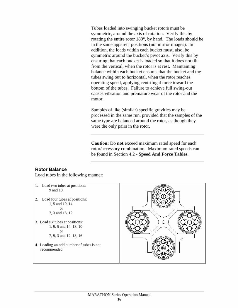
Rotor Balance Load tubes in the following manner:
1. Load two tubes at positions: 9 and 18.
2. Load four tubes at positions: 1, 5 and 10, 14
or 7, 3 and 16, 12
3. Load six tubes at positions: 1, 9, 5 and 14, 18, 10
or 7, 9, 3 and 12, 18, 16
4. Loading an odd number of tubes is not recommended.

MARATHON Series Operation Manual 17
Vibration All centrifuges have critical speeds, at which vibration occurs. As the speed increases, beyond the critical speed, vibration will cease. This inherent condition, also, occurs during deceleration. An imbalanced load intensifies these critical vibrations. Do not continuously operate this centrifuge at observed critical speeds.
Rotor Installation To install the rotor: 1. Place the rotor (with recognition ring facing down, and
all printing facing up) onto the shaft. 2. Using the wrench provided, tighten the locking nut.
Slide the wrench handle to one side in order to utilize maximum torque. Remove the wrench.
3. Place the cover onto the rotor (fixed angle only) using the knob in the center of the cover to position it.
Note: It is important to use the cover on the fixed angle rotors. This cover cuts down on aerodynamic noise and windage, enabling the rotor to achieve maximum specified speed, with minimal noise levels.
Note: Large fixed angle rotors (non miocrotube) must be fully seated on the drive shaft, so that the drive pin engages the slots in the bottom of the rotor.
DRIVE PIN
Figure 1: Fixed Angle Rotor Installation Figure 2: Swinging Bucket Rotor Installation
MARATHON Series Operation Manual 18
Rotor Removal To remove the rotor: 1. Remove the cover (fixed angle only). 2. Using the wrench provided, loosen the rotor locking
nut. Remove the wrench. 3. Remove the locking nut. 4. Lift the rotor off the shaft.
3.2 Starting and Stopping a Run
Read Section 2.5, for a general description of the front panel. The settings displayed on the front panel always govern the operation of the unit. The display above the Program key shows the unit s operating mode. It is important that the unit be in the correct mode for the desired operation.
The PROGRAM display can be one of the following:
blank The unit is in manual operation.
1-99 The unit is under control of the displayed stored program number.
The rest of the display indicates the last parameters selected.
Manual Operation For manual operation, press the MANUAL key so that the program display is blank. Select the desired temperature (21000R only), speed/g-force, run time, acceleration mode, and braking mode. Press START, to start the spin. The rotor will accelerate to 100 - 200 rpm and then coast for a few seconds while the rotor recognition system verifies the rotor and set parameters.
The time display counts down, and displays the time remaining in the current spin, during manual operation. The specified run time begins when the START key is pressed. Braking begins when the set time elapses. Run time does not include braking time.
The spin will stop automatically, at the end of the desired interval. A run can, also, be stopped, at any time, by pressing the STOP key.

MARATHON Series Operation Manual 19
The settings can be changed during a manual run. These changes affect the run in progress. If the time setting is changed, during a run, the unit adjusts the count-down timer, to display the revised setting as the total time of the run. If the new time selected is less than the elapsed time, the run will end.
The unit s mode (settings) cannot be changed during a program mode spin.
3.3 Stored Programs
The Marathon Series has an internal memory capable of holding 99 sets of run parameters. Each set, or program, is stored and can be recalled by selecting a program number (from 1-99). Programs are retained in memory, even if the power is turned off. When necessary, a program can be modified for a particular run or changed permanently. You cannot change the unit's program, rotor/radius, or timing modes, during a spin.
Add/Change Program Press PROGRAM to enter Program mode.
Select a program number with the numeric key pad. The current program parameters will appear on the display.
Modify the desired parameter, including speed/RCF, time, and temperature (if a refrigerated unit), using the numeric key pad or modify the ACCEL or BRAKE modes. Additionally, a radius value may be stored explicitly in the program. The program number will flash, indicating that the program was changed and has not yet been saved.
Make the changes permanent by pressing the SAVE key. The program number will stop flashing, and the new program settings will be displayed. The program will remain in memory until further changes are made.
Because the Marathon 21000(R) has a fully automatic rotor recognition system, the very first rotor that is spun using a particular program will be identified and have its identity automatically stored in the program. If a radius value was not explicitly set by the user, the default radius (or maximum allowable radius) for that rotor will be stored with the program as well. If the user attempts to run a rotor
MARATHON Series Operation Manual 20
other than the one whose identity is stored in the program, a ch hd (check head) message will appear.
If the user wishes to clear the rotor and its radius from the memory banks of the program, he or she need only press the SAVE button. The very first rotor spun after SAVE is pressed will have its identity stored in the program, together with its default radius (if not explicitly entered to the program).
To make changes temporary, press START without pressing the SAVE key. The program display will flash, to indicate that the instrument is not currently operating from program mode. The original program will remain unchanged as long as the SAVE key is not pressed.
Recall Program Press the PROGRAM key to enter program mode. Select the appropriate program number by entering the desired program number on the numeric key pad and press ENTER.
The program s set parameters will be displayed. Press START, to begin this run.
Lock Program Programs can be locked by selecting the desired program on the numeric key pad, and pressing the SAVE key three times. When you scroll to a locked program, the letter L will flash in the program display, after the program number is displayed. To unlock a program, select the desired locked program on the numeric key pad and press the SAVE key three times. Parameters of locked programs cannot be changed.
MARATHON Series Operation Manual 21
3.4 Rotor Recognition System
The Marathon 21000(R) is equipped with a fully automatic rotor recognition system that internally detects and identifies the rotor installed. Since the Marathon 21000(R) was designed to spin a variety of rotors, its software database contains the maximum settable values for speed, RCF, and radius for each. This enables the centrifuge to check and ensure that these parameters as entered by the user do not exceed the prescribed safety limits for the specific rotor.
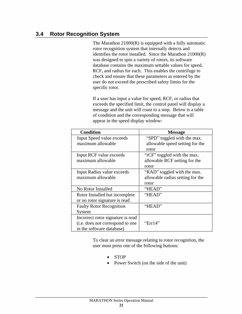
If a user has input a value for speed, RCF, or radius that exceeds the specified limit, the control panel will display a message and the unit will coast to a stop. Below is a table of condition and the corresponding message that will appear in the speed display window:
Condition Message Input Speed value exceeds maximum allowable
SPD toggled with the max. allowable speed setting for the rotor
Input RCF value exceeds maximum allowable
rCF toggled with the max. allowable RCF setting for the rotor
Input Radius value exceeds maximum allowable
RAD toggled with the max. allowable radius setting for the rotor
No Rotor Installed HEAD
Rotor Installed but incomplete or no rotor signature is read
HEAD
Faulty Rotor Recognition System
HEAD
Incorrect rotor signature is read (i.e. does not correspond to one in the software database)
Err14
To clear an error message relating to rotor recognition, the user must press one of the following buttons:
STOP
Power Switch (on the side of the unit)
MARATHON Series Operation Manual 22
3.5 Refrigeration (21000R only)
Refrigerated units refrigerate the rotor chamber whenever the cover is closed and the unit is switched on. Refrigeration is applied, as necessary, to cool the rotor chamber to the currently displayed temperature setting. If you use the key pad, and momentarily display a cold temperature (stepping through stored programs, for example), refrigeration will not be activated.
If the rotor chamber is not at the specified temperature, it will not abort the spin. However, if the rotor chamber differs, at the start of a run, by more than 5°C, from the specified temperature. The °C display will switch between the actual and set/programmed temperatures, until the two temperatures come within 5°C. Press the STOP key, if the run should not continue at the actual temperature.
The unit is not designed for use as a refrigerator. The natural fanning action of the rotor serves to maintain a uniform temperature distribution inside the chamber. At zero RPM, there is no correlation between set and actual chamber temperatures.
Any frost or condensation, that forms in the rotor chamber, should be removed. Allow it to melt, and remove it with a sponge or cloth. When the centrifuge is not in use, turn it off, or leave the cover open (to disable refrigeration).
MARATHON Series Operation Manual 23
3.6 Diagnostic Messages and Error Codes
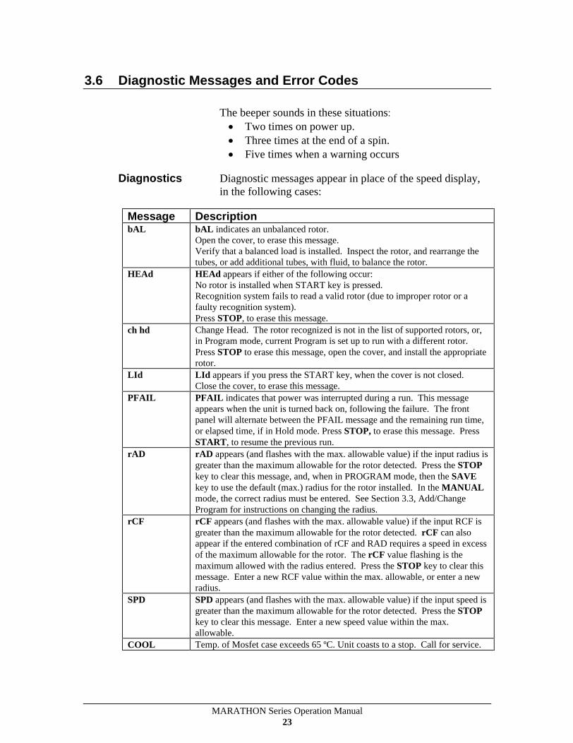
The beeper sounds in these situations:
Two times on power up.
Three times at the end of a spin.
Five times when a warning occurs
Diagnostics Diagnostic messages appear in place of the speed display, in the following cases:
Message Description bAL bAL indicates an unbalanced rotor.
Open the cover, to erase this message. Verify that a balanced load is installed. Inspect the rotor, and rearrange the tubes, or add additional tubes, with fluid, to balance the rotor.
HEAd HEAd appears if either of the following occur: No rotor is installed when START key is pressed. Recognition system fails to read a valid rotor (due to improper rotor or a faulty recognition system). Press STOP, to erase this message.
ch hd Change Head. The rotor recognized is not in the list of supported rotors, or, in Program mode, current Program is set up to run with a different rotor. Press STOP to erase this message, open the cover, and install the appropriate rotor.
LId LId appears if you press the START key, when the cover is not closed. Close the cover, to erase this message.
PFAIL PFAIL indicates that power was interrupted during a run. This message appears when the unit is turned back on, following the failure. The front panel will alternate between the PFAIL message and the remaining run time, or elapsed time, if in Hold mode. Press STOP, to erase this message. Press START, to resume the previous run.
rAD rAD appears (and flashes with the max. allowable value) if the input radius is greater than the maximum allowable for the rotor detected. Press the STOP key to clear this message, and, when in PROGRAM mode, then the SAVE key to use the default (max.) radius for the rotor installed. In the MANUAL mode, the correct radius must be entered. See Section 3.3, Add/Change Program for instructions on changing the radius.
rCF rCF appears (and flashes with the max. allowable value) if the input RCF is greater than the maximum allowable for the rotor detected. rCF can also appear if the entered combination of rCF and RAD requires a speed in excess of the maximum allowable for the rotor. The rCF value flashing is the maximum allowed with the radius entered. Press the STOP key to clear this message. Enter a new RCF value within the max. allowable, or enter a new radius.
SPD SPD appears (and flashes with the max. allowable value) if the input speed is greater than the maximum allowable for the rotor detected. Press the STOP key to clear this message. Enter a new speed value within the max. allowable.
COOL Temp. of Mosfet case exceeds 65 ºC. Unit coasts to a stop. Call for service.
MARATHON Series Operation Manual 24
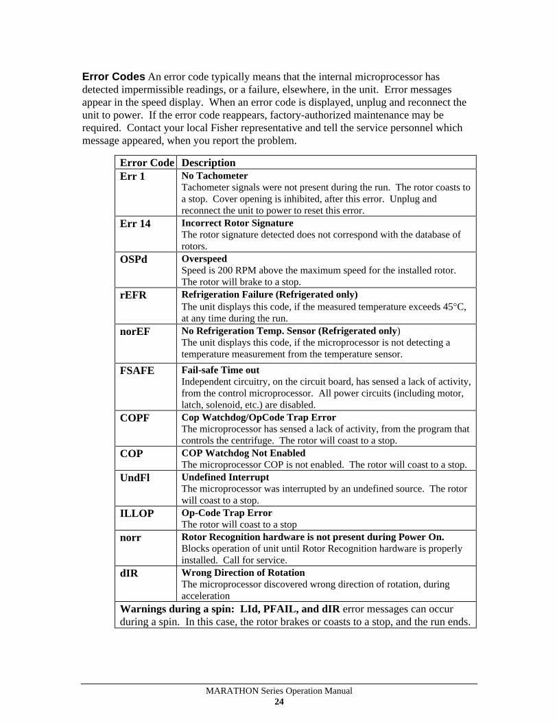
Error Codes An error code typically means that the internal microprocessor has detected impermissible readings, or a failure, elsewhere, in the unit. Error messages appear in the speed display. When an error code is displayed, unplug and reconnect the unit to power. If the error code reappears, factory-authorized maintenance may be required. Contact your local Fisher representative and tell the service personnel which message appeared, when you report the problem.
Error Code
Description Err 1 No Tachometer
Tachometer signals were not present during the run. The rotor coasts to a stop. Cover opening is inhibited, after this error. Unplug and reconnect the unit to power to reset this error.
Err 14 Incorrect Rotor Signature The rotor signature detected does not correspond with the database of rotors.
OSPd Overspeed Speed is 200 RPM above the maximum speed for the installed rotor. The rotor will brake to a stop.
rEFR Refrigeration Failure (Refrigerated only) The unit displays this code, if the measured temperature exceeds 45 C, at any time during the run.
norEF No Refrigeration Temp. Sensor (Refrigerated only) The unit displays this code, if the microprocessor is not detecting a temperature measurement from the temperature sensor.
FSAFE Fail-safe Time out Independent circuitry, on the circuit board, has sensed a lack of activity, from the control microprocessor. All power circuits (including motor, latch, solenoid, etc.) are disabled.
COPF Cop Watchdog/OpCode Trap Error The microprocessor has sensed a lack of activity, from the program that controls the centrifuge. The rotor will coast to a stop.
COP COP Watchdog Not Enabled The microprocessor COP is not enabled. The rotor will coast to a stop.
UndFl Undefined Interrupt The microprocessor was interrupted by an undefined source. The rotor will coast to a stop.
ILLOP Op-Code Trap Error The rotor will coast to a stop
norr Rotor Recognition hardware is not present during Power On. Blocks operation of unit until Rotor Recognition hardware is properly installed. Call for service.
dIR Wrong Direction of Rotation The microprocessor discovered wrong direction of rotation, during acceleration
Warnings during a spin: LId, PFAIL, and dIR error messages can occur during a spin. In this case, the rotor brakes or coasts to a stop, and the run ends.
MARATHON Series Operation Manual 25
4 Applications
4.1 Introduction
This section describes the use of specific rotors and accessories. More detailed information is shipped with the rotor or accessory itself. This section contains five reference sections:
Speed and Force Tables
Derating Table for Dense Samples
Chemical Resistance Table
Decontamination Table
Nomograph
Caution: Do not exceed maximum rated speed for each rotor/accessory combination. Maximum rated speeds can be found in Section 4.2 - Speed And Force Tables.
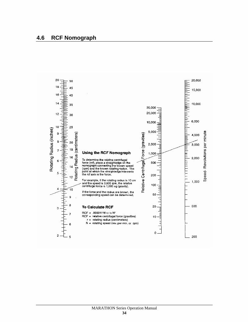
Relative Centrifugal Force (RCF or G-force) at a given speed varies with the rotor, and with the distance away (rotating radius) from the shaft of the centrifuge (center of rotation). The rotating radius is measured to the furthest inside tip of the tube, away from the centrifuge shaft. The Speed and Force Tables indicate the maximum speed and RCF that the 21000/21000R can achieve, with various rotor/accessory combinations. The Derating Table specifies reductions in maximum RPM, when spinning samples with specific gravity above 1.2.

MARATHON Series Operation Manual 26
Use of any tube above its rated RCF can cause tube cracking. To avoid this, compare the G forces, specified in the Speed and Force Tables, with the ratings for the tubes that you are using. If the tubes are not rated for the force that the centrifuge will apply, look up their reduced G force, and enter it on the control panel.
Corrosive Solvents Your centrifuge is made of materials designed to resist immediate attack from most laboratory chemicals. Prolonged exposure should be avoided, by immediately removing the chemical from rotor or assembly. Rotors and accessories placed in the chamber are made of a variety of materials, including aluminum and polypropylene. The Chemical Resistance Table shows the suitability of each material with different classes of reagents.
Section 5.2 describes how to clean and remove corrosion from the chamber, rotors, and accessories. Follow these instructions, and clean spills promptly, to minimize the effect of corrosive chemicals and to avoid expensive repairs.
MARATHON Series Operation Manual 27
4.2 Speed and Force Tables
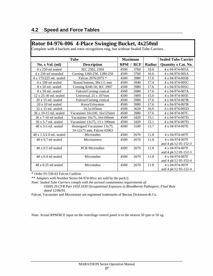
Rotor 04-976-006 4-Place Swinging Bucket, 4x250ml Complete with 4 buckets and rotor recognition ring, but without Sealed Tube Carriers.
Tube Maximum Sealed Tube Carrier
No. x Vol. (ml) Description RPM / RCF Radius
Quantity x Cat. No. 4 x 250 ml sealed IEC 2502, 2504 4500 3760 16.6 4 x 04-974-005A
4 x 250 ml unsealed Corning 1260-250, 1280-250 4500 3760 16.6 4 x 04-974-005A 4 x 175/225 mL sealed Falcon 2076/2075 * 4500 3980 17.6 4 x 04-974-005B
4 x 100 ml sealed Round bottom, 38x111 mm 4500 3940 17.4 4 x 04-974-005C 8 x 50 mL sealed Corning 8240-50, IEC 2997 4500 3980 17.6 4 x 04-974-005G 8 x 50 mL sealed Falcon/Corning conical 4500 3980 17.6 4 x 04-974-007A
12 x 25-30 mL sealed Universal, 25 x 107mm 4500 3400 15.0 4 x 04-974-005E 20 x 15 mL sealed Falcon/Corning conical 4500 3980 17.6 4 x 04-974-007B 20 x 10 ml sealed Kova/Urisystem 4500 3980 17.6 4 x 04-974-007B 32 x 15 mL sealed 16.5x103mm 4500 3620 16.0 4 x 04-974-005D
36 x 10-15 mL sealed Vacutainer 16x100, 16x125mm 4500 3980 17.6 4 x 04-974-007C 36 x 7-10 ml sealed Vacutainer 16x75, 16x100mm 4500 3420 15.1 4 x 04-974-007D 36 x 5-7 mL sealed Vacutainer 13x75, 13 x 100mm 4500 3420 15.1 4 x 04-974-007D 48 x 3-5 mL sealed Hemogard Vacutainer 13x75,
10-12x75 mm, Falcon #2063 4500 3100 13.7 4 x 04-974-007E
48 x 1.5/2.0 mL sealed
Microtubes 4500 2670 11.8 4 x 04-974-007F
48 x 0.7 ml sealed Microtainers 4500 2670 11.8 4 x 04-974-007F and 4 pk/12 05-152-3
48 x 0.5 ml sealed PCR Microtubes 4500 2670 11.8 4 x 04-974-007F and 4 pk/12 05-152-3
48 x 0.4 ml sealed Microtubes 4500 2670 11.8 4 x 04-974-007F and 4 pk/12 05-152-4
48 x 0.25 ml sealed Microtubes 4500 2670 11.8 4 x 04-974-007F and 4 pk/12 05-152-4
* Order 05-538-63 Falcon Cushion ** Adapters with Number Series 04-974-00xx are sold by the pack/2. Note: Sealed Tube Carriers comply with the aerosol containment requirements of:
OSHA 29 CFR Part 1910.1030 Occupational Exposure to Bloodborne Pathogens; Final Rule dated 12/06/91.
Falcon, Vacutainer and Microtainer are registered trademarks of Becton Dickinson & Co.
Note: Actual RPM/RCF input on the centrifuge control panel is to the nearest 50 rpm or 50 xg.
MARATHON Series Operation Manual 28
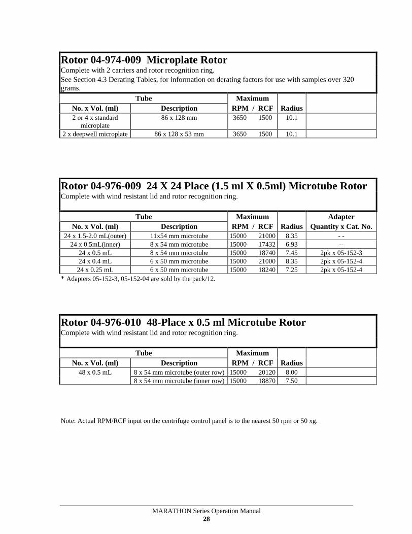
Rotor 04-974-009 Microplate Rotor Complete with 2 carriers and rotor recognition ring. See Section 4.3 Derating Tables, for information on derating factors for use with samples over 320 grams.
Tube Maximum No. x Vol. (ml) Description RPM / RCF Radius
2 or 4 x standard microplate
86 x 128 mm 3650 1500 10.1
2 x deepwell microplate
86 x 128 x 53 mm 3650 1500 10.1
Rotor 04-976-009 24 X 24 Place (1.5 ml X 0.5ml) Microtube Rotor Complete with wind resistant lid and rotor recognition ring.
Tube Maximum Adapter No. x Vol. (ml) Description RPM / RCF Radius
Quantity x Cat. No. 24 x 1.5-2.0 mL(outer) 11x54 mm microtube 15000 21000
8.35 - - 24 x 0.5mL(inner) 8 x 54 mm microtube 15000 17432
6.93 -- 24 x 0.5 mL 8 x 54 mm microtube 15000 18740
7.45 2pk x 05-152-3 24 x 0.4 mL 6 x 50 mm microtube 15000 21000
8.35 2pk x 05-152-4 24 x 0.25 mL 6 x 50 mm microtube 15000 18240
7.25 2pk x 05-152-4 * Adapters 05-152-3, 05-152-04 are sold by the pack/12.
Rotor 04-976-010 48-Place x 0.5 ml Microtube Rotor Complete with wind resistant lid and rotor recognition ring.
Tube Maximum No. x Vol. (ml) Description RPM / RCF Radius
48 x 0.5 mL 8 x 54 mm microtube (outer row)
15000 20120
8.00
8 x 54 mm microtube (inner row)
15000 18870
7.50
Note: Actual RPM/RCF input on the centrifuge control panel is to the nearest 50 rpm or 50 xg.
MARATHON Series Operation Manual 29
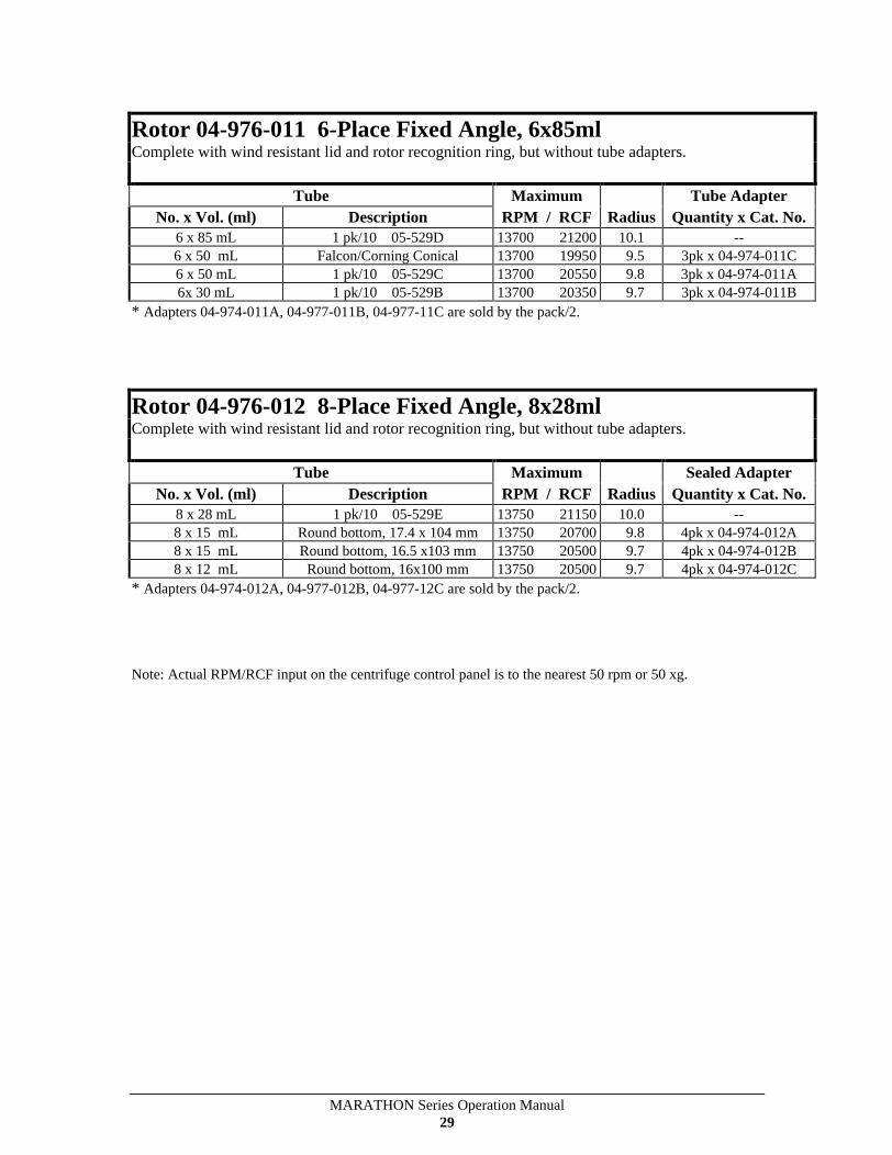
Rotor 04-976-011 6-Place Fixed Angle, 6x85ml Complete with wind resistant lid and rotor recognition ring, but without tube adapters.
Tube Maximum Tube Adapter
No. x Vol. (ml) Description RPM / RCF Radius
Quantity x Cat. No.
6 x 85 mL 1 pk/10 05-529D 13700 21200
10.1 --
6 x 50 mL Falcon/Corning Conical 13700 19950
9.5 3pk x 04-974-011C 6 x 50 mL 1 pk/10 05-529C 13700 20550
9.8 3pk x 04-974-011A 6x 30 mL 1 pk/10 05-529B 13700 20350
9.7 3pk x 04-974-011B * Adapters 04-974-011A, 04-977-011B, 04-977-11C are sold by the pack/2.
Rotor 04-976-012 8-Place Fixed Angle, 8x28ml Complete with wind resistant lid and rotor recognition ring, but without tube adapters.
Tube Maximum Sealed Adapter No. x Vol. (ml) Description RPM / RCF Radius
Quantity x Cat. No. 8 x 28 mL 1 pk/10 05-529E 13750 21150
10.0 -- 8 x 15 mL Round bottom, 17.4 x 104 mm 13750 20700
9.8 4pk x 04-974-012A 8 x 15 mL Round bottom, 16.5 x103 mm 13750 20500
9.7 4pk x 04-974-012B 8 x 12 mL Round bottom, 16x100 mm 13750 20500
9.7 4pk x 04-974-012C * Adapters 04-974-012A, 04-977-012B, 04-977-12C are sold by the pack/2.
Note: Actual RPM/RCF input on the centrifuge control panel is to the nearest 50 rpm or 50 xg.
MARATHON Series Operation Manual 30
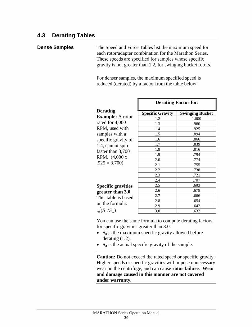
4.3 Derating Tables
Dense Samples The Speed and Force Tables list the maximum speed for each rotor/adapter combination for the Marathon Series. These speeds are specified for samples whose specific gravity is not greater than 1.2, for swinging bucket rotors.
For denser samples, the maximum specified speed is reduced (derated) by a factor from the table below:
Derating Example: A rotor rated for 4,000 RPM, used with samples with a specific gravity of 1.4, cannot spin faster than 3,700 RPM. (4,000 x .925 = 3,700)
Specific gravities greater than 3.0. This table is based on the formula:
( / )S So a
You can use the same formula to compute derating factors for specific gravities greater than 3.0.
So is the maximum specific gravity allowed before derating (1.2).
Sa is the actual specific gravity of the sample.
Caution: Do not exceed the rated speed or specific gravity. Higher speeds or specific gravities will impose unnecessary wear on the centrifuge, and can cause rotor failure. Wear and damage caused in this manner are not covered under warranty.
Derating Factor for:
Specific Gravity Swinging Bucket 1.2 1.000 1.3 .960 1.4 .925 1.5 .894 1.6 .866 1.7 .839 1.8 .816 1.9 .794 2.0 .774 2.1 .755 2.2 .738 2.3 .721 2.4 .707 2.5 .692 2.6 .678 2.7 .666 2.8 .654 2.9 .642 3.0 .632
MARATHON Series Operation Manual 31
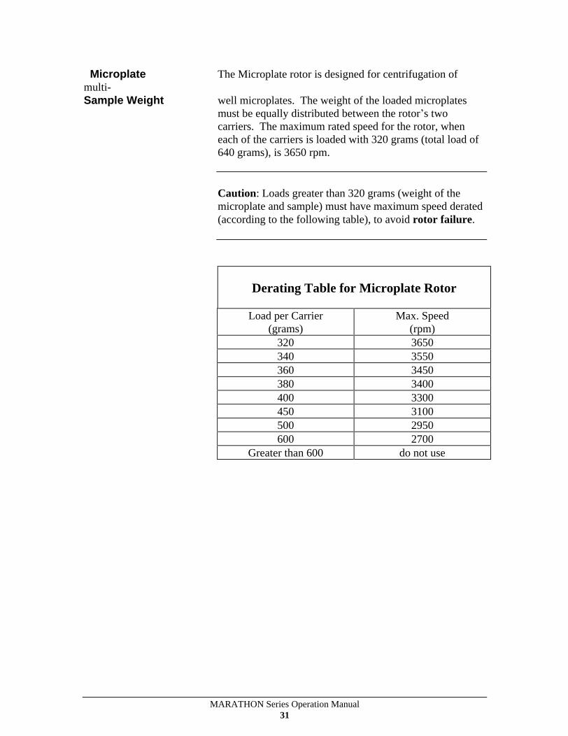
Microplate The Microplate rotor is designed for centrifugation of multi- Sample Weight well microplates. The weight of the loaded microplates
must be equally distributed between the rotor s two carriers. The maximum rated speed for the rotor, when each of the carriers is loaded with 320 grams (total load of 640 grams), is 3650 rpm.
Caution: Loads greater than 320 grams (weight of the microplate and sample) must have maximum speed derated (according to the following table), to avoid rotor failure.
Derating Table for Microplate Rotor
Load per Carrier (grams)
Max. Speed (rpm)
320 3650 340 3550 360 3450 380 3400 400 3300 450 3100 500 2950 600 2700
Greater than 600 do not use

MARATHON Series Operation Manual 32
4.4 Chemical Resistance Table
The Marathon Series is made of materials that are designed to resist attack from most laboratory chemicals. A variety of materials, including aluminum and polypropylene, comprise the rotors and accessories. The Chemical Resistance table shows the suitability of each material, with different classes of reagents.
Note: Chapter 5 describes how to clean and remove corrosion from the chamber, rotors, and accessories. Follow the instructions, and clean spills promptly, to minimize the effect of corrosive chemicals and avoid expensive repairs.
Plastic
Metal Other
PA
PC
PE
PP
PU
NL
DN
CN
NN
PS
TI SS
AL
MB
MG
RR
BN
VN
PF
Acids, dilute or weak E E E E G
E F N F E
G
G
F F N
F E E E
Acids*, strong or conc. E N E E F N N N N F N N N N N
N F G
N
Alcohols, aliphatic E G
E E F E E E N E
E E E E F E E G
E
Aldehydes G
F G
G
G
G
G
G
F N
E E E E E
E N E E
Bases
E N E E N G
N G
F E
E E E E E
G
G
N N
Esters
G
N G
G
N E G
G
E N
E E E E E
N N N E
Hydrocarbons, aliphatic G
F G
G
E N E E E N
E E E E E
N E E E
Hydrocarbons, aromatic F N G
F N N E E E N
E E E E E
N N E E
Hydrocarbons, halogenated F N F F N N G
E G
N
E E E E N
N N F E
Ketones G
N G
G
N N E E E N
E G
G
G
E
N N N E
Oxidizing Agents, strong F N F F N N N N N N
E F N N N
N F E E
Salts
E E E E E E E E E E
E F F F N
E E E E
*For Oxidizing Acids, see "Oxidizing Agents, strong".
PA - POLYALLOMER
TI - TITANIUM
PC - POLYCARBONATE
SS - STAINLESS STEEL
PE - POLYETHYLENE
AL - ALUMINUM
PP - POLYPROPYLENE
MB - MANGANESE BRONZE
PU - POLYURETHANE
MG - MAGNESIUM
NL - MODIFIED PHENYLENE OXIDE (NORYL)
RR - RUBBER
DN - ACETAL HOMOPOLYMER (DELRIN)
BN - BUNA-N
CN - ACETAL COPOLYMER (CELCON)
VN - VITON
NN - NYLON
PF - PHENOLIC FIBER
PS - POLYSTYRENE
Classification of Resistance
E= Excellent
G= Good
F= Fair
N= Not Recommended
MARATHON Series Operation Manual 33
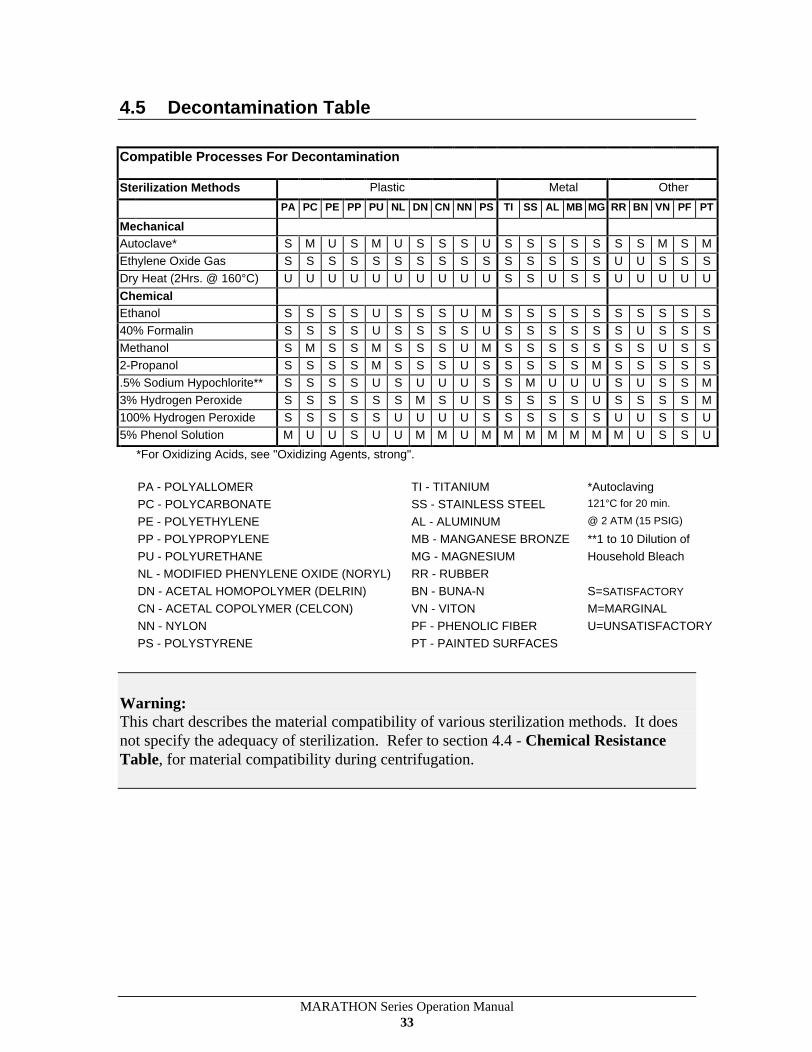
4.5 Decontamination Table
Compatible Processes For Decontamination
Sterilization Methods
Plastic
Metal
Other
PA
PC
PE
PP
PU
NL
DN
CN
NN
PS
TI
SS
AL
MB
MG
RR
BN
VN
PF
PT
Mechanical Autoclave* S
M
U
S
M
U
S
S
S
U
S
S
S
S
S
S
S
M
S
M
Ethylene Oxide Gas S
S
S
S
S
S
S
S
S
S
S
S
S
S
S
U
U
S
S
S
Dry Heat (2Hrs. @ 160°C) U
U
U
U
U
U
U
U
U
U
S
S
U
S
S
U
U
U
U
U
Chemical Ethanol S
S
S
S
U
S
S
S
U
M
S
S
S
S
S
S
S
S
S
S
40% Formalin S
S
S
S
U
S
S
S
S
U
S
S
S
S
S
S
U
S
S
S
Methanol S
M
S
S
M
S
S
S
U
M
S
S
S
S
S
S
S
U
S
S
2-Propanol S
S
S
S
M
S
S
S
U
S
S
S
S
S
M
S
S
S
S
S
.5% Sodium Hypochlorite** S
S
S
S
U
S
U
U
U
S
S
M
U
U
U
S
U
S
S
M
3% Hydrogen Peroxide S
S
S
S
S
S
M
S
U
S
S
S
S
S
U
S
S
S
S
M
100% Hydrogen Peroxide S
S
S
S
S
U
U
U
U
S
S
S
S
S
S
U
U
S
S
U
5% Phenol Solution M
U
U
S
U
U
M
M
U
M
M
M
M
M
M
M
U
S
S
U
*For Oxidizing Acids, see "Oxidizing Agents, strong".
PA - POLYALLOMER
TI - TITANIUM
*Autoclaving
PC - POLYCARBONATE
SS - STAINLESS STEEL
121°C for 20 min.
PE - POLYETHYLENE
AL - ALUMINUM
@ 2 ATM (15 PSIG)
PP - POLYPROPYLENE
MB - MANGANESE BRONZE **1 to 10 Dilution of
PU - POLYURETHANE
MG - MAGNESIUM
Household Bleach
NL - MODIFIED PHENYLENE OXIDE (NORYL) RR - RUBBER
DN - ACETAL HOMOPOLYMER (DELRIN)
BN - BUNA-N
S=SATISFACTORY
CN - ACETAL COPOLYMER (CELCON)
VN - VITON
M=MARGINAL
NN - NYLON
PF - PHENOLIC FIBER
U=UNSATISFACTORY
PS - POLYSTYRENE
PT - PAINTED SURFACES
Warning: This chart describes the material compatibility of various sterilization methods. It does not specify the adequacy of sterilization. Refer to section 4.4 - Chemical Resistance Table, for material compatibility during centrifugation.
MARATHON Series Operation Manual 34
4.6 RCF Nomograph
MARATHON Series Operation Manual 35
5 Maintenance
5.1 Introduction
This chapter explains how to keep your unit in good operating order. It includes instructions for cleaning, decontaminating, and storing. This chapter, also, covers the cover interlock bypass.
See the end of the chapter, for information on service and warrantees.
5.2 Care and Cleaning
Keep your centrifuge clean, to ensure good operation, and to extend its life.
Clean the sample chamber, rotor, and lid, at the end of each work day, and immediately after any spill. To clean the chamber, use a damp sponge, warm water, and a mild liquid detergent, suitable for washing dishes by hand, such as Ivory liquid. Do not use caustic detergents, or detergents that contain chlorine ions. These attack metals.
Remove stubborn stains with a plastic scrub pad. Do not use steel wool, wire brushes, abrasives, or sandpaper. They create corrosion sites. Never pour water directly into the rotor chamber.
MARATHON Series Operation Manual 36
Scrub the rotor s tube cavities with a stiff test tube brush that has end bristles and a non-metallic tip. Dry each part, after cleaning, with a clean, absorbent towel.
If glass breakage occurs, remove all broken pieces immediately. If breakage recurs, replace all adapters and cushions. Particles of broken glass embed in the plastic or rubber accessories. Glass particles can come in contact with new glass tubes, creating pressure points that may result in breakage recurring. Glass particles, in the chamber, grind to a fine gray dust, during centrifugation. This dust can coat the inside of the centrifuge.
Corrosion The manufacturer finishes the rotors and structural accessories to give maximum resistance to corrosion. To maximize the life of the unit, continually inspect the rotor cavities for corrosion, especially if you use chloride ion solutions, such as sodium chloride (saline), and sodium hypochlorite (household bleach), because these solutions attack most metals. Clean the rotor, rotor chamber, and accessories (particularly the sample compartments and bucket cups) thoroughly, after each exposure. Inspect all surfaces, under bright light, for corrosion. Be aware that small crevices grow deeper, eventually resulting in system failure.
If you see any corrosion, remove it immediately, using the following procedure:
1. Follow the cleaning procedure, at the start of this section.
2. Soak the product in mild hand dish washing detergent, and scrub the product thoroughly with a stiff test tube brush. The brush should have end bristles and a non-metallic tip.
3. Soak the product, again, in clear warm water, for a minimum of an hour.
4. Rinse the product in warm water, then in distilled water.
5. Dry the product, thoroughly, with a clean, absorbent cloth.
Caution: If this procedure does not remove the corrosion, discontinue use of the product.
MARATHON Series Operation Manual 37
Storage Store parts on a soft surface, to avoid damage. Rotors and other parts should be clean and dry. Store them open to the air, not in a plastic bag, so that any residual moisture evaporates. Face the parts upward, to avoid moisture retention in the cavities.
Decontamination If tube breakage occurs, releasing toxic, infectious, pathogenic, or radioactive material into the unit, decontaminate the chamber.
Rotors have sealed containers, that provide aerosol containment and, if used as directed, keep spillage confined. If breakage occurs, it may be sufficient to only decontaminate the sealed carriers.
The Decontamination Table, in Chapter 4, lists the sensitivity of various materials to common sterilization procedures. When using a 1-to-10 dilution of household bleach (sodium hypochlorite), to decontaminate metal rotors or accessories, follow decontamination by the corrosion cleaning procedure (See 5.2), since chloride ions attack most metals.
Always decontaminate for the minimum recommended time. If you observe corrosion, remove it, as described earlier; discontinue use of the method; and use an alternate decontamination procedure.
Polypropylene sealed carriers can be autoclaved. Remove any sample tubes, before autoclaving, unless they are completely full of sample. Remove caps, stoppers, and other tube closures, before autoclaving, to keep the tubes from collapsing under pressure. Autoclave the rotor and accessories at 121 ° C @ 15 psig for 20 minutes. Do not stack polypropylene rotors during this process. After cooling, perform a normal cleaning operation, as described above.
Repeated autoclaving seriously degrades the performance of polycarbonate sealing covers.

MARATHON Series Operation Manual 38
5.3 Cover Interlock Bypass
The cover will remain locked, if power fails. If you need to remove samples from the unit, before power is restored, use the cover interlock bypass, after the rotor has come to a stop.
To bypass the cover interlock: 1. Unplug the centrifuge. 2. Locate the hidden plastic plug, underneath the front
ledge of the cabinet. 3. Use a screwdriver to pry out and remove the plug. 4. Pull the attached cord, to release the cover interlock. 5. Replace the plug in the hole.
Do not perform this operation routinely. The centrifuge s cover interlock provides operator safety. It allows the cover to be opened promptly, whenever rotation has stopped.
5.4 Fuses not replaceable by operator
The following fuses are located internally within the centrifuge. They should only be replaced by qualified service personnel.
Power Supply PCB (44486) F1 2.5A - Fast Blow, 250V Power Amplifier PCB (44488) F1 5A - Fast Blow, 250V
MARATHON Series Operation Manual 39
5.5 Condition of Returned Equipment
Contact Fisher Scientific and obtain a return goods authorization (RGA), before returning equipment to the manufacturer. The RGA paperwork includes a Certificate of Decontamination for you to sign. It indicates that you have performed the proper steps for decontaminating the unit.
Warning: All returned units must be decontaminated, free of radioactivity, and free of hazardous, infectious, pathogenic, or toxic materials.
All return equipment shipments will be refused until the signed certificate is received.
You must prepay transportation to the service depot.
5.6 Warranty
Fisher Scientific wants you to be satisfied with the quality of your Marathon Series centrifuge. We warranty the centrifuge for one year, and rotors for seven years. We will repair or replace any of these products that fail, within this period, from the date of its delivery, due to defects in material and workmanship, and we will ship you the repaired product or its replacement at our expense. You must use Fisher Scientific-approved rotors and accessories, and genuine Fisher Scientific spare parts. This warranty does not apply to any instrument that has been abused or repaired without authorization.
THE FOREGOING OBLIGATIONS ARE IN LIEU OF ALL OTHER OBLIGATIONS AND LIABILITIES INCLUDING NEGLIGENCE, AND ALL WARRANTIES, OF MERCHANTABILITY OR OTHERWISE, EXPRESSED OR IMPLIED IN FACT OR BYLAW. THE FOREGOING STATES OUR ENTIRE AND EXCLUSIVE LIABILITY, AND BUYER'S EXCLUSIVE REMEDY, FOR ANY CLAIM OR DAMAGES IN CONNECTION WITH THE SALE OR FURNISHING OF GOODS OR PARTS, THEIR DESIGN, SUITABILITY FOR USE, INSTALLATION, OR OPERATION. FISHER SCIENTIFIC WILL IN NO EVENT BE LIABLE FOR ANY SPECIAL OR CONSEQUENTIAL DAMAGES WHATSOEVER AND OUR LIABILITY UNDER NO CIRCUMSTANCES WILL EXCEED THE PURCHASE PRICE FOR THE GOODS FOR WHICH LIABILITY IS CLAIMED.
MARATHON Series Operation Manual 40
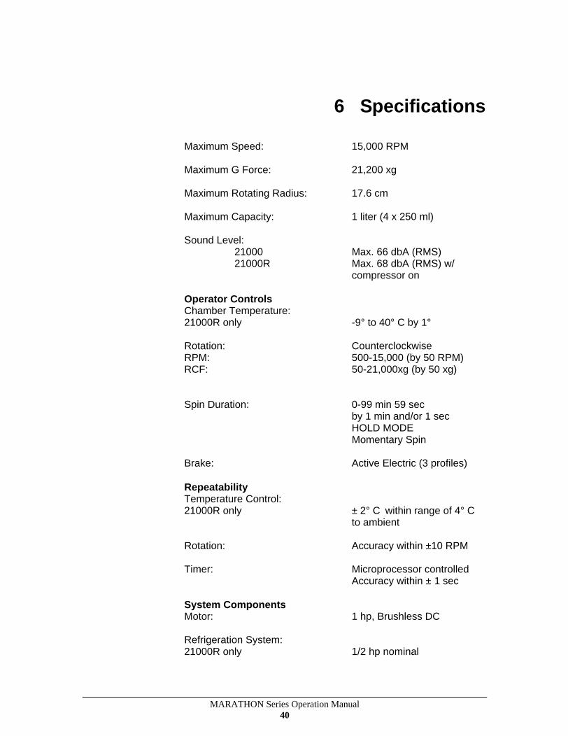
6 Specifications
Maximum Speed: 15,000 RPM
Maximum G Force: 21,200 xg
Maximum Rotating Radius: 17.6 cm
Maximum Capacity: 1 liter (4 x 250 ml)
Sound Level: 21000 Max. 66 dbA (RMS) 21000R Max. 68 dbA (RMS) w/
compressor on
Operator Controls Chamber Temperature: 21000R only -9° to 40° C by 1°
Rotation: Counterclockwise RPM: 500-15,000 (by 50 RPM) RCF: 50-21,000xg (by 50 xg)
Spin Duration: 0-99 min 59 sec by 1 min and/or 1 sec HOLD MODE Momentary Spin
Brake: Active Electric (3 profiles)
Repeatability Temperature Control: 21000R only ± 2° C within range of 4° C
to ambient
Rotation: Accuracy within ±10 RPM
Timer: Microprocessor controlled Accuracy within ± 1 sec
System Components Motor: 1 hp, Brushless DC
Refrigeration System: 21000R only 1/2 hp nominal

MARATHON Series Operation Manual 41
Refrigerant: non-CFC 21000R only R-404A (7.9 oz Lo-V Models)
R-404A (6.9 oz Hi-V Models)
Operating pressures: 20 psi (low side) at 4° C (21000R only) 250 psi (high side)
Max sample temperature rise: 21000 only 7° C above ambient*
*except for 6 x 85 mL Fixed Angle Rotor
Power Requirements and Output s/n Description Electrical Requirements
6464
21000 Ventilated 115 VAC, 60 Hz 6465
21000 Ventilated 220-240 VAC, 50/60 Hz 6466
21000R Refrigerated 115 VAC, 60 Hz 6467
21000R Refrigerated 220-240 VAC, 50 Hz 6468
21000R Refrigerated 230 VAC, 60 Hz
Current: 15 Amps
Heat Output: 21000 2014 Btu/hr 21000R 3925 Btu/hr
Dimensions Height: 21000 and 21000R 15.5 in (39.4 cm)
Width: 21000 20.3 in (51.4 cm) 21000R 28.0 in (71.1 cm)
Depth: 21000 and 21000R 23.4 in (59.4 cm)
Shipping Dimensions: Height 27 in (68.6 cm) Width 36 in (91.4 cm) Depth 30 in (76.2 cm)
Unit Weight: 21000 159 lb. (73 kg) 21000R 222 lb. (101 kg)
Shipping Weight: 21000 206 lb. (94 kg) 21000R 269 lb. (122 kg)
Specifications Subject To Change Without Notice