
Manuscript 0
25
1 Modeling and control of doubly fed induction generator with a disturbance 1 observer: A stator voltage oriented approach 2 E.Emre ÖZSOY (1) , Edin GOLUBOVIC (2) , Asıf ŞABANOVIC (3) , 3 Seta BOGOSYAN (4) , Metin GÖKAŞAN (5) , 4 (1,4,5) Istanbul Technical University, Istanbul, Turkey 5 (1,4) {eozsoy,gokasan}@itu.edu.tr, (3) [email protected] 6 (2,3) Sabancı University, Istanbul, Turkey, 7 {edin,asif}@sabanciuniv.edu 8 Abstract—The popularity of renewable energy conversion systems, especially wind 9 energy has been increasing in recent years. Doubly fed induction generator (DFIG) 10 based wind energy systems are intensively used due to their wide range of active and 11 reactive power controllability. Conventional DFIG control structures consist of 12 decoupled PI rotor current controllers with stator flux orientation and machine 13 parameter dependent compensating terms. The accuracy of stator flux calculation is 14 dependent on how accurately the stator resistance is known. Integration problems also 15 exist and additional low pass filters are implemented to accurately calculate the stator 16 flux. In this study, machine dependent compensating terms are estimated with a first 17 order low pass filter disturbance observer. Therefore, a single proportional (P) controller 18 is sufficient to control decoupled rotor currents. The proposed controller structure is 19 implemented on a Matlab/Simulink platform with the parameters of 500KW DFIG used 20 in MILRES (Turkish National Wind Energy) project. The proposed controller is also 21 experimentally validated in an experimental setup. 22 Keywords; Doubly fed induction generator, disturbance observer, wind energy 23 Symbol Nomenclature 24 i sa , i sb , i sc : Stator a, b and c phase currents i sd , i sq : Stator d and q axis currents 25 i ra , i rb , i rc : Rotor a, b and c phase currents i rd , i rq : Rotor d and q axis currents 26
-
Upload
arun-kumar -
Category
Documents
-
view
214 -
download
0
description
program information
Transcript of Manuscript 0

1
Modeling and control of doubly fed induction generator with a disturbance 1
observer: A stator voltage oriented approach 2
E.Emre ÖZSOY (1), Edin GOLUBOVIC (2), Asıf ŞABANOVIC (3), 3
Seta BOGOSYAN (4), Metin GÖKAŞAN (5), 4 (1,4,5)
Istanbul Technical University, Istanbul, Turkey 5 (1,4)
{eozsoy,gokasan}@itu.edu.tr,(3)
[email protected] 6 (2,3)
Sabancı University, Istanbul, Turkey, 7
{edin,asif}@sabanciuniv.edu 8
Abstract—The popularity of renewable energy conversion systems, especially wind 9
energy has been increasing in recent years. Doubly fed induction generator (DFIG) 10
based wind energy systems are intensively used due to their wide range of active and 11
reactive power controllability. Conventional DFIG control structures consist of 12
decoupled PI rotor current controllers with stator flux orientation and machine 13
parameter dependent compensating terms. The accuracy of stator flux calculation is 14
dependent on how accurately the stator resistance is known. Integration problems also 15
exist and additional low pass filters are implemented to accurately calculate the stator 16
flux. In this study, machine dependent compensating terms are estimated with a first 17
order low pass filter disturbance observer. Therefore, a single proportional (P) controller 18
is sufficient to control decoupled rotor currents. The proposed controller structure is 19
implemented on a Matlab/Simulink platform with the parameters of 500KW DFIG used 20
in MILRES (Turkish National Wind Energy) project. The proposed controller is also 21
experimentally validated in an experimental setup. 22
Keywords; Doubly fed induction generator, disturbance observer, wind energy 23
Symbol Nomenclature 24
isa, isb, isc : Stator a, b and c phase currents isd, isq : Stator d and q axis currents 25
ira, irb, irc : Rotor a, b and c phase currents ird, irq : Rotor d and q axis currents 26

2
vsa, vsb, vsc : Stator a, b and c phase voltages vsα, vsβ : α and β axis stator voltage 1
vra, vrb, vrc : Rotor a, b and c phase voltages vsd, vsq : Stator d and q axis voltages 2
vrd, vrq : Rotor d and q axis voltages Rs, Rr : Stator and rotor resistances 3
Ps, : Stator Active Power Qs : Stator reactive Power 4
Ls, Lr : Stator and rotor inductances Lm : Mutual inductance 5
Lrb : Base value of rotor inductance ∆Lr : Disturbance of Lr 6
p : Number of pole pairs ωs : Stator electrical speed 7
ωm : Rotor mechanical speed Tm : Mechanical Torque 8
Te : Electrical Torque b : Viscous friction constant 9
θs : Stator electrical angle θr : Rotor electrical angle 10
Ts : Sample Time s : Laplace operator 11
kp, kq : Proportional gain of controller 12
1. Introduction 13
Research on renewable energy conversion systems is of great importance due to 14
the rapid consumption of fuel resources and environmental issues. Wind energy 15
conversion systems appear to be the fastest growing technology and most of the 16
electrical energy generated by renewable sources is from wind energy conversion 17
systems [1]. DFIG based wind turbines have important advantages compared to other 18
wind energy conversion systems. For example, 30% of rated stator power is sufficient for 19
the rotor side inverter circuit to achieve 4-quadrant stator active and reactive power flow 20
with a speed variation around ±25%. This reduces the cost and complexity of the overall 21
system. 22

3
Considerable research studies are encountered about DFIG modeling and control 1
in the literature. DFIG dynamic equations are fully written in [1, 2]. A complete 2
simulation and modeling for high power DFIG wind farms are given in [3]. Reduced 3
order DFIG dynamic model was also proposed in this study due to simulation 4
constraints. 5
From orientation frame point of view, basically, stator flux [4] and stator voltage 6
orientation [5] can be encountered in which the position of the stator-flux or voltage 7
space vector is aligned with the d-axis of the d-q frame. Stator flux orientation control 8
techniques are dependent on the accuracy of stator resistance information. Integration 9
problems also exist and additional low pass filters are implemented to accurately 10
calculate stator flux [4]. The effect of stator resistance value can be neglected in flux 11
calculation and stator voltage orientation could be applied by adding 90ο phase shift to 12
voltage angle. This may cause additional coupling effect in active and reactive power 13
control, which can be compensated by implementing additional controllers in the outer 14
loop as given in [5]. It is claimed in [6] that controller performances of both orientation 15
frames are equivalent. 16
The idea of stator voltage orientation with disturbance observer starts with [7]. 17
The scheme of [7] consists of simulation results of direct stator active and reactive 18
power control with disturbance observer. 19
Synchronization is also another issue to smoothly connect DFIG to the grid. Grid 20
and generated stator voltages must be collinear, which means that equal in phase and 21
amplitude, before DFIG is connected to the grid to prevent high currents. Majority of 22

4
the contributions focus on a mode of operation that DFIG is already connected to the 1
grid. Synchronization procedure is comprehensively analyzed in [8] with important 2
citations. 3
There are also considerable research studies which are looking from different 4
control perspectives. Direct power control strategies which directly control stator power 5
without rotor current control loops are reported in [9, 10]. Sliding mode controller 6
structures [11, 12] are also important contributions which deal with energy 7
maximization and robustness against disturbances. There are also reputable studies 8
which consider robustness against grid voltage problems [13, 14, 15]. 9
This study focuses on designing a novel robust stator voltage oriented DFIG 10
controller structure with low pass filter first order disturbance observer. The main 11
contribution of this paper is to achieve a simpler controller compared to basic 12
conventional schemes given in [4, 5]. Machine dependent compensating terms are 13
accurately estimated with the first order low pass filter disturbance observer. This 14
prevents the necessity to accurately know the machine parameters which may 15
deteriorate according to physical conditions. Decoupled proportional rotor current 16
controllers are sufficient to separately control stator active and reactive power. The 17
parameters of the actual 500KW DFIG in the MILRES (National Wind Energy 18
Systems) project are used for the Matlab/Simulink based system model. The proposed 19
current controller is also implemented on 1.1KW DFIG experimental test bed. 20
The rest of the paper is organized as follows. The dynamic equations of DFIG 21
are given in chapter 2. Chapter 3 provides a controller structure based on a first order 22

5
disturbance observer. Simulation results of the proposed control structure are 1
demonstrated in chapter 4. Experimental results are in chapter 5. Finally, 6th chapter 2
gives the conclusion and proposes the future work. 3
2. DFIG Dynamic Equations 4
Before writing the dynamic equations Lr value could be written as follows. 5
L� � L�� � ΔL� (1) 6
Lrb is the inductance value at fundamental frequency. ∆Lr is the value which is affected 7
by frequency and other physical disturbances. DFIG dynamic equations in [1, 2] can be 8
rewritten as follows; 9
V� � L� �� � R�I� � L� �� ���I� ��I�� (2) 10
V� � L�� �� � ΔL� �� � R�I� � L� �� � N��I� � N�I�� (3) 11
The matrices V, I, M and N are defined as follows; 12
V � �v v��� � � �i i��� (4) 13
�� � � 0 L�ω�"L�ω� 0 #, �$ � % 0 &'&�" &'&� 0 ( (5) 14
N� � � 0 L�ω�"L�ω� 0 #, N� � % 0 &'&�" &'&� 0 ( (6) 15
All the rotor variables are referred to the stator side. The electromagnetic torque can be 16
given as; 17
T*� � +,pL��i�i�� " i��i�� (7) 18
Stator active and reactive Power equations can be written as; 19

6
P� � +, �v�i� � v��i��� (8) 1
Q� � +, �v��v� " v�0��� (9) 2
The equation of motion can be given as; 3
12314 � 56 �T� " T* � b.ω�� (10) 4
3. Control System 5
3.1 Stator Voltage Angle Calculation 6
Rotating frames could be differently aligned in the literature. Stator voltage 7
angle is aligned with d axis, with vs=vsd and vsq=0. The voltage vectors and reference 8
frames are in figure 1. 9
The voltage angle could be calculated by using, 10
θ� � arctan�?�@?�A� (11) 11
However, phase lock loop (PLL) techniques which are more robust against 12
voltage disturbances are widely used for phase and frequency detection of the voltage 13
signal. Different PLL techniques could be encountered in the literature [16]. A basic 14
PLL algorithm which is given in figure 2 is used in simulations and experiments of this 15
study. Grid voltages, transformed into dq coordinate system are the inputs of the 16
algorithm. Q component of the voltage could be forced to be zero with a PI controller. 17
Output of the PI controller is the grid frequency. Integration of the grid frequency is the 18
position of the signal. This position is used in the abc-dq calculation. 19

7
3.2 Design of Current Controllers 1
DFIG rotor voltage equation in (3) must be rewritten to simply design 2
proportional rotor current controllers. All currents and voltages could be measured in real 3
applications without any problems. However, machine parameters may deteriorate 4
according to physical conditions. The aim of rewriting the equations is to separate the 5
machine dependent and independent terms. Therefore, a simpler controller structure 6
could be achieved. Rotor dynamics in (3) could be rewritten as follows; 7
�� � B�&�C � �" D�&� V� " &'&� �� � N��I� � N�I�� " ΔL� ��EFFFFFFFFFFFFGFFFFFFFFFFFFHB�IJ�� (12) 8
The vector K$1L�is defined as V�M� � Nv�M� v��M�O that is considered as parameter 9
dependent disturbance terms. Equation (12) could be simplified as follows. 10
�� � B�&�C � V�M� (13) 11
Derivative of errors for rotor currents can be written as; 12
P�� � ��QR� " �� (14) 13
Where ε� � �ε� ε���� 14
(13) and (14) could be written with (14) as follows; 15
P�� � " B�&�C " �" ��QR� � V�M�� (15) 16
Next, the desired closed loop dynamics can be written as; 17
1TU14 � KW$ � 0 (16) 18
Where K � �k k�� is defined as proportional controller gain. 19
If (15) is written to (16) desired closed loop dynamics is rewritten as follows; 20

8
" B�&�C � �d��QRdt � V�M�� " Kε� � 0 (17) 1
Rotor voltage equations could be obtained by rewriting (17) 2
V��*Z � Lrb�Irref� � Vrdis � Kεr� (18) 3
If the effect of 1^UU_`14 is neglected, control effort could be expressed as follows. 4
V��*Z � Vrdis � LrbKεr (19) 5
3.3 Disturbance Observer 6
In this section, the derivation of the disturbance observer is presented. The vector K$1L� 7
is the disturbance term which is dependent on physical conditions. Controller structure 8
could be finalized, if the disturbances are correctly estimated. 9
V�M� � V� " L�� �� (20) 10
Writing (22) in s domain and implementing first order low pass filter disturbance 11
observer concept [17]; 12
Va�M� � �V� " L�� �� � b�cb (21) 13
The estimation error can be expressed as; 14
V�M� " Va�M� � �V� " L�� �� � " �V� " L�� �� � b�cb � �1 " b�cb�V�M� (22) 15
The estimation error converges to zero. The vector Ke$1L� � Nfg$11L� fg$h1L�O is 16
parameter dependent estimated disturbance. The term g is the cut-off frequency of the 17
low pass filter in radians. It is obvious from (21) that vg�M� and vg��M� are independent from 18
machine parameters. As a result, block diagram in figure 3 can be obtained. Decoupled 19
control of active and reactive power could be achieved by controlling irq and ird 20

9
respectively. This control structure can be implemented in speed, torque or power 1
control of DFIG. Maximum power point tracking (MPPT) algorithms can be followed 2
according to any wind turbine dynamics. 3
4. Simulation Results 4
More accurate simulation platform is obtained compared to [3] without necessity 5
of reduced order models by using discretized model of DFIG. 100µs sample time in 6
Matlab/Simulink is used in simulations. Inverter dynamics are neglected. 500KW DFIG 7
parameters [18] which will be used in MILRES project is given in Table 1. All the rotor 8
parameters are referred to the stator side. Control system can work in different scenarios. 9
In this study, generator is controlled according to speed control strategy. 10
Machine parameters dependent compensating terms of control structure is 11
estimated by disturbance observer. Basically, two different step response tests are 12
applied in one simulation at different time instants. Speed reference is changed from 60 13
to 90 rad/s (from sub synchronous to super synchronous speed) at 10th second. Wind 14
torque reference is changed from 3000Nm to 5000Nm at 12th second. It is expected that 15
system must follow the speed (Figure 4) and wind torque (Figure 5), while accurately 16
estimating disturbance terms. There is a huge current torque and current increase at 10th 17
second of simulation. The reason of high current and torque is the speed step which is 18
deliberately applied with a high speed controller gain in order to check the performance 19
of the controller structure. Control system could handle this dramatic step and kept 20
stable. ird reference (Figure 6) is kept zero during the simulations. 21

10
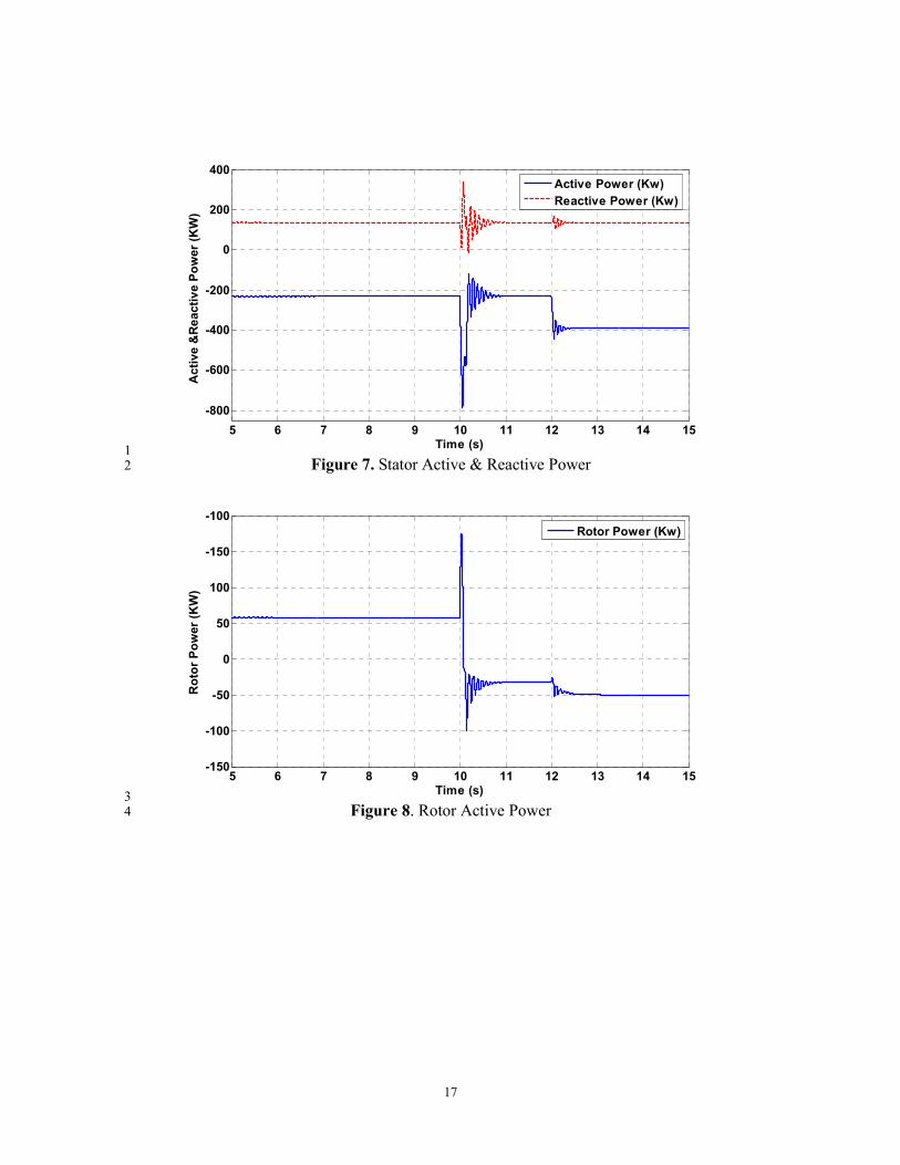
It is obviously seen from the simulation results that DFIG dynamic model works 1
properly and compensating terms are accurately estimated by disturbance observer (Fig. 2
9-10). Rotor power is changing the direction while the speed changes from 3
subsynchronous to supersynchronous speed (Figure 8). Active and reactive stator 4
powers are decoupled (Figure 7). Performance of the speed controller could be modified 5
(Figure 4) according to physical conditions. However, focus of the simulation results is 6
accurately estimating compensating terms. 7
5. Experimental Results 8
Experimental setup in Figure 11 is used in the experiments. A squirrel cage 9
induction machine (SCIM) driven by a commercial inverter which represents the wind. 10
DFIG plate data is given in Table 2. Controller algorithm is generated in dSPACE 11
DS1103 by using Controldesk C language. Sample time of the control structure is 12
100µs. Semikron Semistack (21f_b6u_e1cif_b6ci_12_v12) inverter used in 13
experiments and 120VDC constant voltage power is directly applied to DC link. 14
Switching frequency is 10 kHz. Low pass filter cut-off frequency (g) is chosen as 1200. 15
Proportional gains of the controllers (kp and kq) are 100. These values are found in trial 16
and error method in the experiments without any algebraic calculations. 17
5.1 Experiment 1 18
The aim of the first experiments is to show that decoupled control of Ird and Irq 19
rotor currents separately changes the stator active and reactive power respectively. DFIG 20
is rotated in constant subsynchronous speed by SCIM. Ird and irq step response tests are 21

11
applied in different experiments, and the change of stator reactive and active power is 1
demonstrated respectively. 2
It is obvious from the experimental results that both rotor current controllers 3
accurately change stator active and reactive power (Figure 13 and 16). Compensating 4
terms also change (Figures 14 and 17 )when step responses are applied. 5
5.2 Experiment 2 6
The main objective of DFIG based wind turbines is decoupled control of active 7
and reactive power. Control structure given in figure 3 is implemented by using basic PI 8
power controllers in the outer loop while generator is driven by SCIM at arbitrary 9
speed. Active and reactive power step response tests are applied and decoupled control 10
of active and reactive stator power could be achieved. 11
Conclusion 12
Decoupled control of active and reactive power with a first order low pass filter 13
disturbance observer is fully demonstrated with the simulation and experimental results. 14
It is shown that compensating terms are accurately estimated by the disturbance observer 15
in simulations. Experimental results validate the accuracy of the proposed control 16
method by effectively achieving stator active and reactive power flow. 17
References 18
[1] Montenau I, Bratcu AI, Cutululis NA, Ceanga E. Optimal Control of Wind Energy 19
Systems: Towards a Global Approach. Advances in Industrial Control: Springer, 2008. 20
[2] Leonard W. Control of electric drives. 3rd Edition. Berlin, Heidelberg, Springer: 21
New-York, 2003. 22

12
[3] Akhmatov V. Analysis of dynamic behavior of electric power systems with large 1
amount of wind power. PhD thesis, Technical University of Denmark, April 2003. 2
[4] Pena R, Clare JC, Asher GM. A doubly-fed induction generator using two back-to-3
back PWM converters and its application to variable speed wind energy system. Proc. 4
IEE, 1996; vol. 143, pp.231–241. 5
[5] Muller S, Deicke M, and De Doncker RW. Doubly fed induction generator systems 6
for wind turbines, IEEE Ind. Appl. Mag. May/Jun. 2002, vol. 8, pp. 26–33. 7
[6] Li S, Challoo R, Nemmers MJ. Comparative study of DFIG power control using 8
stator-voltage and stator-flux oriented frames. Power&Energy Society General Meeting, 9
2009; Canada: IEEE, pp. 1-8. 10
[7] Demirok E. Grid-connected variable speed generator applications with doubly-fed 11
induction machine, Msc. thesis , Sabancı University, Summer 2007. 12
[8] Tapia G, Santamaria G, Telleria M, Susperregui A. Methodology for smooth 13
connection of doubly fed induction generators to the grid. IEEE Trans. on Energy 14
Conversion, Dec. 2009; Vol. 24 pp. 959-971. 15
[9] Xu L, Cartwright, P. Direct active and reactive power control of DFIG for wind 16
energy generation. IEEE Transactions on Energy Conversion, 2006, Vol. 3, pp. 750-17
758. 18
[10] Zhi D, Xu L. Direct power control of DFIG with constant switching frequency and 19
improved transient performance. IEEE Trans. on Energy Conversion, March 2007; 20
Vol.22, pp.110-118. 21

13
[11] Battista HD, Mantz RJ. Dynamical variable structure controller for power 1
regulation of wind energy conversion systems, IEEE Trans. On Energy Conversion, 2
2004; Vol.4, pp.756-763. 3
[12] Beltran B, BenBouzid MEH, Ahmet-Ali T. High order sliding mode control of a 4
DFIG based wind turbine for power maximization and grid fault tolerance. Electric 5
Machines and Drives Conference (IEMDC), 2009; USA: IEEE, pp 183-189. 6
[13] Luna A, Rolan A, Medeiros G, Rodrigez P, Teodorescu R. Control strategies for 7
DFIG wind Turbines Under Grid Fault Conditions, 35th Annual Conference of IEEE 8
Industrial Electronics, (IECON) 2009; Portugal pp 3886-3891. 9
[14] Rodriguez P, Luna A, Teodorescu R, Iov F, Blaabjerg F, Fault ride-through 10
capability implementation in wind turbine converters using a decoupled double 11
synchronous reference frame PLL, European Conference on Power Electronics, 2007; 12
Denmark: pp. 1–10. 13
[15] Zhou P, Yikang H, Sun D. Improved direct power control of a DFIG-Based wind 14
turbine during network unbalance. IEEE Transactions on Power Electronics, 2009; Vol. 15
11, pp. 2465-2474. 16
[16] Blaabjerg F, Teodorescu R, Liserre M, Timbus AV. Overview of control and grid 17
synchronization for distributed power generation systems, IEEE Transactions on 18
Industrial Electronics, 2006 Vol. 5, pp. 1398-1409. 19
[17] Ohnishi K, Shibata M, Murakami T, Motion control for advanced mechatronics, 20
IEEE/ASME Transactions on Mechatronics, March 1996 Vol.1, pp 56–67. 21

14
[18] TUBITAK Report. Generatör Elektriksel ve Manyetik Analiz Detay Tasarım 1
Raporu (DFIG), R-1.1.1”, June 2013. 2
FIGURES 3
4
Figure 1. Voltage Vectors and Reference Frames 5
6
Figure 2. PLL algorithm 7
β
α
sds VV =r
sθ rθ
rIr
∫

15
1
Figure 3. Proposed Control Diagram 2
3
4 Figure 4. Actual and Reference Speed 5
dtp msr )( ωωθ ∫ −=
dis
rdv̂
dis
rqv̂
5 6 7 8 9 10 11 12 13 14 1555
60
65
70
75
80
85
90
95
Time (s)
Speed (rad/s)
Speed (rad/s)
Reference

16
1
Figure 5. Generator Torque & Wind Torque 2
3 Figure 6. Rotor currents 4
5 6 7 8 9 10 11 12 13 14 15-10000
-8000
-6000
-4000
-2000
0
Time (s)
Torque (Nm)
Generator Torque
Wind Torque
5 6 7 8 9 10 11 12 13 14 15-100
-50
0
50
100
150
200
250
Time (s)
Ird &Irq (A)
Irq (A)
Ird (A)
17
1 Figure 7. Stator Active & Reactive Power 2
3 Figure 8. Rotor Active Power 4
5 6 7 8 9 10 11 12 13 14 15
-800
-600
-400
-200
0
200
400
Time (s)
Active &Reactive Power (KW)
Active Power (Kw)
Reactive Power (Kw)
5 6 7 8 9 10 11 12 13 14 15-150
-100
-50
0
50
100
-150
-100
Time (s)
Rotor Power (KW)
Rotor Power (Kw)

18
1
Figure 9. Estimated & Modeled Disturbance Terms (vdisd) 2
3
Figure 10. Estimated & Modeled Disturbance Terms (vdisq) 4
5
5 6 7 8 9 10 11 12 13 14 15
-80
-60
-40
-20
0
20
40
60
80
Time (s)
Vdisd (V)
Dist. Observer Vdisd (V)
DFIG Model Vdisd (V)
5 6 7 8 9 10 11 12 13 14 15-150
-100
-50
0
50
100
150
Time (s)
Vdisq (V)
DFIG Model Vdisq (V)
Dist. Observer Vdisq (V)

19
1
Figure 11. Experimental Set up 2
3
Figure 12. Experiment 1-A Irq step response 4
~
2) Rotor Current Meas.
TRANSFORMER
commercial
drive
DFIG SCIM
Control
dSPACE3)Grid Voltage Meas.4)Stator Voltage Meas.
1) Stator Current Meas.
5) DFIG Speed Meas.
GRID
=
INVERTER
GRID
PWM
Signals
100
VDC
6 6.5 7 7.5 8 8.5 9 9.5 10-1
-0.5
0
0.5
1
1.5
2
2.5
3
Time (s)
Irq(A)
Irq (A)
Reference

20
1 Figure 13. Experiment 1-A Change of Active & Reactive Power 2
3
Figure 14. Experiment 1-A Compensating Term Sq 4
6 6.5 7 7.5 8 8.5 9 9.5 10
-20
0
20
40
60
80
100
Time (s)
Active & Reactive Power (W
)
Active Power
Reactive Power
6 6.5 7 7.5 8 8.5 9 9.5 100
5
10
15
20
25
30
35
40
Time (s)
Vrdisq
Vrdisq (V)

21
1
Figure 15. Experiment 1-B Ird step response 2
3
Figure 16. Experiment 1-B Change of Active & Reactive Power 4
6 6.5 7 7.5 8 8.5 9 9.5 100
0.5
1
1.5
2
2.5
Time (s)
Ird (A)
Ird (A)
Reference
6 6.5 7 7.5 8 8.5 9 9.5 10-40
-30
-20
-10
0
10
20
30
40
Time (s)
Active & Reactive Power (W
)
Active Power (W)
Reactive Power (W)

22
1
Figure 17. Experiment 1-B Vrdis_d 2
3
4
Figure 18. Experiment 2-A Active Power Response Test 5
6 6.5 7 7.5 8 8.5 9 9.5 105
10
15
20
25
Time (s)
Vrdisd (V)
Vrdisd(V)
0 1 2 3 4 5 6 7 8 9 10-10
0
10
20
30
40
50
Time (s)
Ps (W)
Active Power (Watt)
Reference

23
1
Figure 19. Experiment 2-A Reactive Power at Active Power Step Response Test 2
3
4
Figure 20. Experiment 2-B Reactive Power Response Test 5
6
0 1 2 3 4 5 6 7 8 9 10-15
-10
-5
0
5
10
15
Time (s)
Qs (Watt)
Qs (Var)
Reference
0 1 2 3 4 5 6 7 8 9 10-10
0
10
20
30
40
50
Time (s)
Qs (Watt)
Qs (VAr)
Reference

24
1
Figure 21. Experiment 2-B Active Power at Reactive Power Response Test 2
TABLES 3
Table 1. DFIG parameters in simulation 4
Stator Power (Ps) 457.6 KW
Rotor Power (Pr) 61.4 KW
Stator Voltage 690 V Number of Poles (p) 4
Slip Variation 0.25
Nominal Torque 6784 Nm Synchronous Speed 750 rpm
Stator Resistance (Rs) 0,018 ohm
Rotor Resistance (Rr) 0,021 ohm
Mutual Inductance (Lm) 0,011 H
Stator Inductance (Ls) 0,012 H
Rotor Inductance (Lr) 0,012 H
Turn Ratio (ns/nr) 4
Moment of Inertia 22 kgm2
5
6
7
8
0 1 2 3 4 5 6 7 8 9 10-15
-10
-5
0
5
10
15
Ps (Watt)
Time (s)
Ps (W)
Reference

25
1
Table 2. DFIG plate data in experiments 2
Power 1,1 KW Stator Voltage 220/380 V (D/Y) Stator Current 6,4/3,7 A
Power Factor 0,67
Speed 1360 rpm Rotor Voltage 70 V
Rotor Current 12 A
3
4
5