
MANUFACTURING TECHNOLOGY (For GATE & IES)...MANUFACTURING TECHNOLOGY (For GATE & IES) Dr CH.V.S....
210
MANUFACTURING TECHNOLOGY (For GATE & IES) Dr CH.V.S. PARAMESWARARAO M.Tech, Ph.D Professor & Principal Sri Raghavendra Institute of Sc.&Tech. VINJAMUR-524228 Nellore dt, A.P [email protected] 09849291903
Transcript of MANUFACTURING TECHNOLOGY (For GATE & IES)...MANUFACTURING TECHNOLOGY (For GATE & IES) Dr CH.V.S....

MANUFACTURING TECHNOLOGY (For GATE & IES)
Dr CH.V.S. PARAMESWARARAO
M.Tech, Ph.D
Professor & Principal
Sri Raghavendra Institute of Sc.&Tech.
VINJAMUR-524228
Nellore dt, A.P
09849291903

SYNOPSIS
METAL CASTING Definition:
Pouring molten metal in to a cavity of shape as if component and allow to freeze.
Advantages:
i) Complex shapes which are difficult to machine can be produced. ii) Heavy and bulky components
i) Unidirectional properties, better vibration damping properties are obtained Disadvantages:
i) High melting point metals can’t be casted economically. ii) Thin walled sections can’t be casted by sand casting iii) Handling of hot materials is difficult.
Metals that can be easily casted
CI, MI, GCI, WI, Steel and all Non ferrous alloys
Elements of a Foundry
1. Pattern - Definition, Types, Materials, Colors, Allowances, Applications 2. Molding - Sands, Methods, Types, Elements Sands - Natural, Synthetic, Loam sands Binders - Organic, Inorganic - Additives - Water 3. Pouring - Melting equipment, Pouring equipment 4. Cooling 5. Fettling Inspection & defects, Tools Pattern: Definition: Replica or facsimile of the component to be made
Types: Single piece pattern, Multi piece pattern, loose piece pattern, match plate pattern, sweep pattern, skeleton pattern, segmental pattern, Follow board pattern, gated pattern.
Materials: Wood, Metal, plaster, wax, plastic.
Wood: White piene, Mahogany, Teak, Deodar, sisal, kail, Maple, Cherry etc.
Metal: CI, Steel, Al, Brass, White metal, Zn, etc.
Plaster: Zipsom sulphate
Plastic: PVC, HDPE, Nylon
Colors: Red : Surfaces to be machined
Black : Surfaces to be left unmachined
Yellow : Core prints
Red stripes on yellow base : Seats for loose pieces
Black stripes on yellow base : Stop offs
Clear or no color : Parting surface

Allowances:
i) Shrinkage allowance : To be provided on all surfaces
a) Liquid shrinkage : Catered by raiser
b) Solid shrinkage : Catered by pattern
ii) Machining allowance : To be provided on those surfaces which are to be machined
iii) Draft allowance : To be provided on all vertical surfaces.
iv) Distortion allowance : To be provided on thin sections v) rapping or shaking To be provided
Allowances : on Horizontal surfaces a Negative allowance
Pattern Selection depends on:
1. No. of components to be produced
2. Dimensional accuracy and surface on casting
3. Method of molding
4. Shape and complexity and size of the casting
5. Molding materials
6. Casting design parameters
7. Chances of repeat orders.
Mould:
Definition: It is a void created in a compact sand mass which when filled with molten metal, will produce a casting.
Molding materials: Molding sand comprised of sand, binder, additive and water (2 to 8%)
Sands:
Natural sands:
Synthetic sands: Oil sands, Mollases sands
Loan sands: Have high clay content (up to 50% clay)
Refractorys sands: Silica sand, Magnesite, Zircon, Dolomite, Olivine, graphite etc.
Properties of Sand:
Refractoriness, flow ability, green strength, Dry strength, Hot strength, permeability, Adhesiveness, cohesiveness, collapsibility
Grain size:
Size is expressed in grain fineness number. (GFN)- determined by Sieve analysis method. Large grains or coarse grains:Used for large casting with less surface finish, high permeability. Fine grains are used for small, precision castings with high finish. Have low permeability Tests on Sands: Grain fineness test, clay content test, Moisture content test, Test of permeability, Refractoriness test, strength test, Mould hardness test, Core hardness test, Compacting factor test. BINDERS : : Added to induce the required properties for molding Organic binders: Dextrin, Mollasses, Linseed oil, cereal binders, Resins In organic binders: Bentonite, Kaolonite, Limonite, Ball clay, fire clay, fullers earth.

ADDITIVES: Added to improve the existing properties and to stabilize those properties.
Coal dust, sea coal, cereal binders, silica flour, wood flour, pitch, reduces expansion defects. Dextrin, Mollasses, fuel ill etc. Molding Methods: Bench Molding :Small components Floor Molding :Small and Medium size components, more in number Pit Molding : Big and large castings Machine Molding: Medium and large castings. (With match plate pattern) Molding Machines: Jolting M/c, squeezing M/c, Jolt-squeeze M/c, sand slinger, Diaphragm M/c.
Types of Moulds:
Green sand mould, dry sand mould, skin dried mould, loam mould, cement bonded mould, plaster mould, core sand mould, Co2 mould, shell mould, metallic mould, investment mould.
Types of casting processes Sand mould casting, plaster mould casting – Carthiosis, Antioch – processes Die casting – Pressure, gravity, slush Pressure – Hot chamber, cold chamber, centrifugal, Co2 mould casting Elements of Mould Cores: Horizontal, vertical, Balanced, Hanging ,wing(wire) or kiss core. Chaplets: Core supports Chills: Aids the casting to get directional solidification.
Internal and external chills. Feeding systems of sand mould: Pouring basin, sprue, runner, gate, riser – open, blind Gate – Top, bottom, parting line, side, circular. Casting defects: Blow holes, porosity, shrinkage, mis run & cold shuts, inclusions, hot tears, cuts & washes, Metal penetration, drop, fusion, shift, swells, rattails & buckles, hard spots, run out, crushes, warpage, distortion
1. Visual inspection 2. Inspection for dimensional accuracy 3. Sound test 4. pressure test 5. Radiography test 6. Ultra sonic test 7. Magnetic particle test 8. Die penetrate test
Design of feeding elements:
Feeding elements: 1) Pouring Basin 2) Sprue 3) Runner 4) In gate 5) Riser
Pouring Basin : A wide open curved space for pouring the liquid Metal. Sprue: A down word tapered conical section connecting the runner and pouring basin (vertical
passage for molten metal)
Runner: A trapezoidal or hemi spherical horizontal passage of molten metal connecting the in gate with down sprue.
In gate: Entry point of molten metal in to the cavity
Riser: Cylindrical reservoir of metal to feed the cavity during liquid shrinkage.
Filling time:
Top Gating:

Vg=√2ght ht= total height of pouring
Volumetric flow, Q = Ag Vg Ag=Area of gate
Time of filling, tf = V/Q V = Volume of cavity (casting)
Bottom gating: Vg=√2g(ht-h)
tf=Am/Ag 1/√2 g 2[√ht-√ht-hm]
Time of filling for riser tf/r = Ar/Ag [1/√2 g] 2√ht hm=height of mould for Top gating
tf/r = Ar/Ag 2/√2 g [√ht-hm] for Bottom gating Total time of filling Tf = tf + tf/r Sprue Design: To avoid aspiration effect:
A3/A2 = √hc/ht Sprue height = (ht-hc) A3 = area of spruce at its exit A2 = area of spruce
hc = height of cup/pouring basin ht = Total height of pouring
In gate design: designed by considering as a weir. Gating ratio is sprue exit area: runner area: In gate area Free height of molten metal in the runner
h = 1.6 3√Q2/gb
2 + V
2/2g mm , Height of the in gate h1 = h-5 mm
Q = Metal flow rate, mm3/Sec
b = gate width, mm V = Metal velocity in runner, mm/Sec g = acceleration due to gravity, mm/Sec
2
Raiser Design: Time of solidification ts = K(V/SA)
2 V = Volume
SA = Surface area
ts/Riser > ts/casting (V/SA)2
Riser > (V/SA)2
casting

METAL JOINING
Temporary joint : Bolted joints
Semi permanent joint: Riveted joint
Permanent joint : Welded joint
WELDING:
The basic purpose of welding is to provide a means to join pieces by raising their temperature to the fusion point so that they form a sort of pool of molten metal at the ends to be joined.
Concept of a weld:
A welded joint or weldment between two metal pieces is the result of fusion of metal, followed by freezing of this fused metal at the junction.
The common sources of heat generation for effecting the desired fusion of metal are:
1) Fire of smiths forge e.g. Forge welding
2) Electric arc e.g. SMAW, SAW, CAW, TIGW,MIGW, STUDW, Electro slag W
3) Gas flame e.g. O2-C2H2, C3H6, C3H8, H2,(CH4+H2)
4) Gas plus electric arc e.g. [H], PAW
5) Electrical resistance e.g. Spot, Seam, Projection, Butt
6) Chemical reaction e.g. Thermit W, Explosive welding
7) Energy ray e.g. EBW, LBW
8) Mechanical energy e.g. Friction W, USW
9) Allied processes e.g. Soldering, Brazing, Adhesive bonding
Classification
i) Solid state welding e.g. Forge welding, stud welding, Explosive welding,
Friction Welding and USW.
ii) Liquid state (Fusion) welding
Forge welding: It is a method of welding metals by heating them in a black smith’s forge to the plastic state and then hammering them together on the anvil to form a welded joint. It is employed for wrought Iron, L-C-steels. e.g Sickles
Electric arc welding:
It is a fusion welding process in which no mechanical pressure is applied for joining the metals. In this, the metals to be joined are heated locally to the melting temperature, by creating an electric arc, and then allowed to solidify to form the welded joint. Consumable electrode is connected to positive terminal of the power supply. Non consumable electrode is connected to negative terminal of the power supply.
Solid fluxes used are Rutile (TiO2), cellulosics, sodium silicate, silica flour, Asbestos clay, CaCo3, ferro manganese.
Suitable for medium gage fabrication work
Gas welding: Heat released by burning high calorific value gases in the presence of oxygen is used to rise the temp of work metals for joining.
Gases used are: Acetylene is produced by moistening calcium carbide stone.
Krishna
Highlight

CaC2 + H2O C2H2 + Ca(OH)2
Acetylene will be burned in two stages for the complete release of heat.
C2H2 + O2 2CO + H2 + 448 kj/mol
4CO + 2H2 + 3O2 4CO2 + 2H2O + 812 kj/mol
Ratio of Acetylene to oxygen by volume 2:5
Flames:
Neutral flame 3100oC O2 : C2H2 1:1 GI, Low carbon steels, WI, can be welded
Carborizing flame 2900oC O2 : C2H2 2:3 H-C steels, carbides, Oxygen free copper Alloys, Ni, Al
Oxidizing flame 3300oC O2 : C2H2 3:2 Non Fe alloys.Cu, Mn, Mn- steels
Gas plus electric arc welding:
Atomic Hydrogen welding: H2 → [H] + [H] – 100 700 cals
Temperature rise up to 3700oC
Uses: Repair works of dies, moulds, ship hulls etc.
Plasma Arc Welding: Plasma (Ionized gas) imposed on the welding zone, evolving heat, melting 10,000oC
temp rise and joining occurs.
Electrical Resistance welding:
Heat generated Q = I2Rt/J I = Current flow
Rc = 0.85 ρ/nπr R = Resistance. ρL/A
T = time of current pass-Sec
J = Heat equivalent
Operating voltages : 5-25 v
Operating currents : 100-20000 Amp.
Time : 0.06 to 3 seconds
Materials : 0.5mm to 3mm thick
The Resistance developed between the plates/sheets to be joined for the current flow develops heat, which melts the metal, and on the application of pressure, the joining occurs. This method is used for low gage fabrication (sheet metal) work.
Spot welding
Seam welding – It is a continuous spot welding
Projection welding – It is multi spot welding
Butt welding
Dissimilar/similar materials of same/different heights can be joined.
Chemical energy Thermit welding: Thermit is a mixture of Aluminum powder, metal oxide which when ignited results in a non-explosive exothermic reaction. The heat so generated melts and reduces the metal oxide to metal in liquid form which is used for joining.
8Al + 3 Fe3O4 9Fe + 4 Al2O3 + 3310 kj/mol. (at 2450oC)

This method is used for heavy gage fabrication work. e.g.: Rails, ship sterns, cable conductor
EXPLOSIVE WELDING:
Radiant Energy welding processes:
A stream of electrons or a beam of electro-magnetic radiation is used to provide heat at point of welding. The heat is generated where energy beam strikes the work piece. This process can be carried out in vacuum or at low temperature and hence the welds of highest quality can be produced.
These processes are useful where narrow beam of welding, accuracy is required with superior materials.
Electron Beam Welding In EBW heated filament is used as a source of electrons, which are made to flow towards and through an annular field anode. This beam of electron is imposed on weld point materials up 150 mm thick can be welded. Materials that can be welded are:Super alloys, Refractory Metals, S.S., Ti, Be,Molybdynum, Zirconium Laser Beam Welding: A concentrated coherent light beam impinges at desired spot to melt and weld metal. Light beam (LASER) can be obtained from RUBY, CORRUNDAM etc. Temperature rise 20000
oC.
Mechanical Energy Friction Welding: One work piece is held stationary and the other is rotated in the chuck of a friction welding machine. As they are brought to rub against each other under pressure, they get heated due to friction. When the desired forging temperature is attained throughout the rubbing cross section of the work piece, the rotation is stopped suddenly and the axial pressure is increased to cause a forging action and hence welding. Low temp. melting materials, Tin, Zinc, Lead, plastics are welded by this method. Ultrasonic welding A metallic tip vibrating at ultrasonic frequency is made to join a thin piece to a thicker piece supported on an anvil. 20 KHZ – 60 KHZ frequency Eg: Motor armatures, Al, gold lead wire connections. Dissimilar metals in solar collectors. ALLIED Processes In these processes, a filler material having melting point lower than solidus of the metal parts being joined is used. Soldering: It is a process of joining metal usually in the form of over lapped joints, by making the filler metal flow in to the gap between them by capillary action. The filler material used is called solder or load and has a melting point between 185
o to 275
oC. It is an alloy of Tin and lead in ratios 40/60 , 50/50 or 60/40. FLUX: zinc
chloride or Resin. Uses: Copper plumbing, electronic industry Brazing: It is a process of joining metals by using a non-Ferrous filler metal having a melting point above 450
oC but
below the solidus of the base metal. No melting of base metal is involved and the filler metal (spelter) spreads by capillary action between the pieces being joined. Flux: Chlorides, fluorides and Borates of alkali metals. e.g. BORAX Spelter is an alloy of Cu + Zn + Ag + Cd It is a medium strength joint. Both lap & butt joints can be done. Adhesive Bonding Resins (Un saturated polymers) are applied between the components to be joined forming a bond. Eg. QUICKFIX, FEVICOL etc.. MECHANICS In solid state welding the important factors are: (i) Surface deformation (ii) Surface filming (iii) recrystallisation (iv) Diffusion

Principles of Fusion (Liquid state) welding: Fusion welding processes may be either autogeneous or homogeneous. There are 3 zones (i) Fusion zone (ii) Heat affected un melted zone around fusion zone (iii) Un affected original part Important factors governing the fusion welding process:
i) Characteristics of heat source ii) Weld pool (Nature of deposition of the filler material in the fusion zone) iii) Heat flow characteristics in a joint iv) Gas – metal or slag-metal reactions in the fusion zone v) Cooling of fusion zone with the associated contraction, residual stresses and metallurgical
changes. Principle of Arc welding Emission and ionization of an electric arc Initially a good contact is made between the electrode and the work. There after the electrode is with drawn. As a result the metallic bridges start breaking, thus increasing the current density per bridge. Finally, the current density raised to such a high value that the bridges start boiling. Under such conditions, the electrons come out of both the surfaces by a process known as thermionic emission. Obviously, the electron (negatively charged) coming out of the anode are pulled back, where as those coming out of the cathode are also attracted towards the anode.
The rate at which the electrons are emitted from a hot surface is I = Cθ2 e
-B/ Where I is in Ampers/cm
2
K = Boltz man const. = Absolute temperature
φ = thermionic work function C = Constant β = φe/K Once started, the arc itself becomes a source of ions through a process of ionization. These ions are attracted by cathode and the resulting collisions keep the cathode hot. The total current in the arc is carried by two sets of electrodes. The first set emitted by cathode, is called primary electrons the second set, known as secondary electrons, is produced as a result of ionization of the arc gap. -- With W & C electrodes, the primary electrons carry the most of the current, where as with Cu & Al
electrodes, the secondary electrons carry most of the current. -- Inter particle collision is called thermal ionization The definite amount of energy required producing ionization in a given atom or molecule is called
ionization potential. -- Arc characteristic: V = A1+B1l Power characteristics V = A + BI linear characteristic Parabolic characteristic -- An increase in arc length increases the Voltages and current falls and melting rate decreases. -- The power of an arc varies with its length and there is an optimum length at which the arc power is
maximum. Resistance welding
Contact Resistance Rc = o.85 /nπr Rate of heat generated per unit area Q = V
2/Rc
= I2Rc
Q = I2Rt jouls
n = number of bridges per unit area
ρ = Resistivity of the material r = radius of bridge.
Rc = ρL/A

MACHINE TOOLS & METAL CUTTING
Machine tools: Lathe, drilling, milling, Boring, Shaping, Planing, Lapping, Grinding, Honing ,etc..
Parts : Bed, column, Tool holding, Work holding, Feed mechanisms, Drive mechanisms.
Tools : Single point tools, Drill bits, Milling cutters, Reamers, Broaches, Hones, Grinding wheels, Taps,etc..
Operations : Plain turning, Facing, Step turning, Grooving, Taper turning, Chamfering, Drilling, Trepaning, Boring, Counter boring, Counter sinking, Tapping, Threading, Reaming, Broaching, Lapping, Honing, Grinding, Buffing, etc..
* Material removal occurs due to plastic shear of metal with cutter by formation of chips.
Mechanism of chip formation:
Types of chips : Continuous chips, Discontinuous chips, Continuous chips with built up edges.
Methods of Machining:
1. Orthogonal or 2-D cutting 2. Oblique or 3-D cutting
Single Point cutting tool:
Nomenclature : Shank, flank, face, heel, nose, cutting edge.
Designation : ASA: αb - αs - θe - θs – ce – cs -R mm
ORS: i - α - γ - γ1- ce - λ -R mm
Shear plane angle, Tan ϕ = r cos α /(1-r sin α )
r = chip thickness ratio or chip compression ratio = t/tc = l/lc =vc/v
ζ = 1/r = tc/t = chip reduction factor
Shear strain, S = cot ϕ + Tan ( ϕ - α)
Relation between velocities :
Vs/V = cos α / cos (ϕ-α) V = cutting velocity, Vs =Shear velocity, Vc = Chip velocity
t = f sin λ , b = d/sin λ λ = cutting edge angle.
Force Relations
Merchant circle:
Tangential cut force, Fc
Thrust or Axial or Holding force, Ft
Friction force , F = Fc sin α + Ft cos α
Normal force, N =Fc cos α - Ft sin α
Coeff. Of friction µ = F/N =( Fc tan α + Ft ) / (Fc – Ft tan α)
Friction angle , Tan β = µ
Shear force , Fs = Fc cos ϕ - Ft sin ϕ
Normal force, Fn = Fc sin ϕ + Ft cos ϕ

Shear area As = b t / sin ϕ
Shear stress τs = Fs /As
Normal stress σs = Fn / As
Shear stress τs = Fc sec ( β - α ) cos ( ϕ+β-α ) sin ϕ / bt
ϕ = 45 + ( α - β )/2 Merchant relation
ϕ = 45 + α - β Lee & Shaffer relation
Cutting Power Pc = Fc V, Motor power Pm = Pc/ ηmotor
Energy or power lost in friction, Pf = F Vc
Energy or power in shear, Ps = Fs Vs
TOOL WEAR
1) Flank wear, 2) Crater wear on tool face 3) Localised wear such as rounding of cutting edge, 4) Chipping of cutting edge.
TOOL LIFE It is defined as actual time of machining between two sharpenings.
Taylors Tool life equation , VTn = Constant.
VTn d
m f
x = Const.
V = Cutting velocity, m/min. d = depth of cut, mm
T = tool life , min. f = feed , mm/ rev. n = tool index.
Economics of Metal Cutting At higher cutting speeds , machining cost will be low but tooling cost will be higher, in turn total cost will be high.
At lower cutting speeds, machining cost will be higher but tooling cost will be lower, in turn total cost will be high.
Optimum cutting velocity is one , the velocity of cutting at the total cost will be minimum.
Fig.
Vopt = C[ cm .n / ct(1-n)]n
cm = machining cost/min. ct = tooling cost
Topt = Tc (1-n)/n C = taylor index Tc = Tool change time
Machinability index ,% = cutting speed of metal for 20 min. tool life / cutting speed of free cutting steel for 20 min. tool life
Heat generation during metal cutting
The energy supplied for cutting is transformed in to heat at shear zone (primary source) and at tool chip interface ( secondary source).
Due to heat generation, temp. will raise at shear zone (work-tool interface),friction zone(tool – chip interface).
Total Power consumption, W = Fc V = Wp + Ws
Wp = Heat generated at primary (shear zone) deformation.
Ws = Heat generated in secondary (friction) deformation zone.

Wp = F Vc = F r V
Temp. raise (shear) primary deformation zone ,
θp = ( 1- ∧ ) Wp/ ρ cp v t b
∧ = fraction of primary heat which goes to work piece
ρ = density of work piece material
cp = Sp.heat of work piece material
∧ = 0.15 ln [27.5/θTanϕ] θ = Thermal number = ρCPv t/K
K = Thermal conductivity of work material.
Temp. rise in secondary deformation zone,θs θs = 1.13√θ t Cs/l [Ws/ρCpvbt]
l = length of contact between tool and clip, l = tc[1+tan (-∝)]
Find temp θ = θo+θp+θs θo = initial temp. of work piece.
Multi point cutting tool operations Drilling: Drill bit will have two principal cutting edges.
If the total advancement of drill per revolution (the feed rate) is f, then the share of each cutting edge is f/2 because each lip is getting the uncut layer, of the top surface of which has been finished by the other lip 180
o a head. (During 180
o rotation, the vertical displacement of drill is f/2).
The uncut thickness t, and width of cut W are
t1 = f Sin γ/2 W = D sin γ/2 Where γ = half point angle
rake angle ∝ = Tan-1
(2r/D )Tanθ/Sin γ r = D/4 ϕ = helix angle
Force analysis is as if single point cutting tool.
Total Thrust force F = 5 FT Sin γ
Total moment M = 0.6 Fc D. D = cutter dia.
MILLING: Types: Horizontal milling, vertical milling, up milling, down milling, slab milling, slot milling, form milling etc..
Uncut thickness t1max = (f / NZ) sin γ
Sin γ = 2√d/D f = feed per min.
T1 max = (2f / NZ)√(d/D) N = Speed rpm
Z = No. of teeth
γ = angle included by contact arc.
Force analysis is similar to that of SPT.
Cutting Fluids:
Functions:
Properties:
Types:

UN CONVENTIONAL OR NON TRADITIONAL MACHINING METHODS
Used for (i) New materials with low machinability
(ii) Dimensional and accuracy requirements (iii) A higher production rate and economy
Classification:
Energy Type Mechanics of Material removal
Energy source Process Ra (µm) MRR
--- Plastic shear Mech. Motion of Tool/Job
Conventional maching
-- High
Mechanical Erosion Mech/Fluid motion
AJM, WJM, USM -- 15 mm3/min
Electro chemical
Ion displacement Electric current ECM 0.2-0.6 1000 mm
3/min
Mech, & Electro chemical
Plastic shear & Ion displacement
Ele. Current & Mech. Motion
ECG 0.2-0.4 --
Chemical Corrosive reaction Corrosive agent CM 0.5--2 10 mm3/min
--- Fusion & vaporization
Electric spark EDM 0.5
--- Fusion & vaporization
High speed electrons
EBM 0.5
Thermal --- Powerful radiation
LBM 0.05
--- --- Ionized substance
IBM 1.5
--- --- Ionized substance
PAM 1.5

TOOL ENGINEERING Degrees of freedom:
A component in space is free to move along x,y, z axes and free to rotate about x,y,z axes.
These movements are called Degrees of freedom.
Location: The component is to be placed in correct position by arresting all degrees of freedom .
Methods of arresting the degrees of freedom:
ii) 3-2-1 Location method : This principle states that to locate a work piece, it has to be placed and held against three points in a base plane, two points in a vertical plane, one point in a plane square with the first two. The above planes should be square with each other and the points should be spaced as far as possible.
iii) 4-1-1 Location method: Work piece should be located on 4 points; one must be an adjustable, used for locating rough surfaces.
Principles of locations:
i) Locating surfaces must be as small as possible and location must be done from a machined surface.
ii) Sharp corners in the locating surfaces must be avoided. iii) As many degrees of freedom of movements as necessary to maintain the required accuracy
should curtail. Redundant location features need not be provided. iv) Adjustable locators should be provided for rough surfaces. v) Locating pins should be tapered and be easily accessible and visible to the operator. vi) Location should be designed fool proof. vii) Enough clearance for clearing machining burrs should be provided. viii) Operator safety.
Types of locations
1) Cylindrical location 2) Conical location 3) V-location 4)Flat (plane) location 5)Profile location 6)Adjustable location 7)Diamond pin location.
Locators:
1)Cylindrical pins 2)conical pins 3)spring loaded adjustable pins 4)screw type adjustable pins 5)plate locators 6)form locators 7)diamond pin locators 8) V-blocks
Redundant location: If two locators curtail same degrees of freedom, one of locator is said to be redundant location. This must be avoided.
Clamping : Used arrest all degrees of freedom in conjunction with locating devices.
Principles of clamping
1) Clamps should always be arranged directly above the points supporting the work. 2) Clamps should be applied to the component where it is rigid and well supported. 3) Quick acting clamps should be used where ever possible. 4) Fiber pads should be riveted to clamp faces. 5) The position of the clamps should be such that it provides best resistance to cutting
forces. 6) Clamps should not cause deformation of work piece. 7) Pressure of the cutting force should act against the solid part of jig but not against clamps. 8) All clamps and adjustments should be on component loading and unloading side. 9) Arrangements should be made to lift the clamp away from the work, or otherwise clear it,
when the clamping load is released.

Types of clamping devices
1.lever clamp (strap clamp) : Solid heel clamp, loose-guided heel clamp, clamp using heel in casting, hinged clamps, two way clamps
2.screw clamps :wing nut, thumbscrew
3.Wedge operated clamps.
4.Equilizer clamps.
5.CAM clamps.
6.Toggle clamps.
7.Pneumatic clamps
8.Rack &pinion clamps.
9.Non-conventional clamps.
Jigs and fixtures
Jig or a fixture is a device on which components can be quickly positioned in the correct relationship to the cutting tool and quickly clamped before machining. Jigs and fixtures are employed where mass production with high degree of accuracy and interchangeability, at a competitive cost is required and to maintain low manufacturing cost to invoke industry efficiency.
Jig is that part which incorporates bushes and guides the tools for cutting. Fixture holds and locates the work with out necessarily providing guidance for the tools.
Jig is usually not fixed to machine table by clamping.
Jigs are used for mass drilling, reaming and tapping.
Fixture is a structure holding and locating a component or work piece in a definite position for a specific operation but is does not guide the cutting tool. Fixtures are used for milling, turning and grinding operations.
Design principles for jigs & fixtures
1. The method of location and clamping should be such as to reduce idle time to a minimum.
2. Location principles
3. Clamping principles
4. Work supports
i) Number of fixed supports on any surface should not be more than three and should be as far as possible.
ii) The area of supporting should be least possible so that it can be kept clean. iii) The supports should be easily visible and accessible to the operator.
5. Stability and rigidity
6. Clearance for chips
7. Fool proof design
8. Safety of the operation
9. Fixtures should be robust in design
10. Tenon strips should be provided for accurate and quick location of fixture on machine bed.

Elements of Jigs & Fixtures i) Body ii) Location elements iii) Clamping devices iv) Tool guide v) Additionals.
Types of Jigs:
1. Plastic jig 2. Channel jig 3. Box jig 4. pot jig
5. Plate jig 6. Turn over jig 7. Trunion type jig
8. Angle jig 9. Indexing jig 10. Shaft drill jigs.
11. Universal jigs.
Types of fixtures:
Milling fixtures: 1. Key way milling fixture
2. Straddle milling fixture.
3. Up milling fixture.
4 . Down milling fixture.
Turning fixtures:
1. Face plate 2. Chucks 2- jaw chuck
3-jaw chuck -> self centering, individually movable.
4- jaw chuck
Combination chuck.
3. Collects: a) pull in collets b) push out collets (c) Dead length collets
4. Mandrels: a) plain mandrel ( b) Tapered mandrel (c) Threaded mandrel
Essential characteristics in proper design of jigs and fixtures:
1. Dimensional accuracy 2. Ruggedness 3. Adaptability 4. Economy 5. Salvageability 6. Attractive appearance 7. Accessibility 8. Simple design, safe and fool proof. 9. ease of handling 10. easy to construct.

METAL WORKING
Metal forming methods
1. Direct tension type process. e.g. stretch forming, expanding, recessing
2. Direct compression type Process. e.g. Rolling. Forging, extrusion, sheet metal work
3. In direct or combined tensile & compression process.
e.g. Wire drawing, sheet metal drawing, spinning, up set bulging
4. Bending process
5. Shearing process – e.g. Joggling, twisting
Hot working & Cold working
Mechanical working of metals is defined as an intentional deformation of metals plastically under the action of externally applied force. Two types: 1) Hot working: deforming the metal plastically at a temp. above recrystallisation
2) Cold working: Working on metal below recrystallisation temp.
Hot working
Advantages:
a) No strain hardening, unlimited deformation b) Brittle materials can be worked c) Less force requirement and lower capacity machines d) Porosity in the material is eliminated e) Impurities in the form of inclusions are broken up and distributed through the metal f) Grain refinement occurs, causing decrease in hardness and strength, increase in ductility and
resistance to impact strength. g) Defects like blow holes, internal porosity, cracks etc. get welded up. h) Self-annealing occurs and recrystallisation takes place.
Limitations
a) Too high temperature may cause phase change, where as too low temperature may result in excessive work hardening.
b) Some material which are brittle at high temp. can not be hot worked. c) Scale formation, poor surface finish, chance of decarburization, chance of oxidation. d) Difficult to achieve dimensional accuracy. e) Difficulty in handling f) Reduced tool life.
Procesess : Rolling, Forging, pipe Drawing, Spinning, extrusion etc.
Cold working
Advantages:
1. Increase the strength and hardness of material due to strain hardening. 2. No decarburisation, no oxidation, better dimensional accuracy, surface finish. 3. Increases the ultimate strength, yield strength, hardness, fatigue strength and residual stresses.
Limitations:
1. Excessive cold working give rise to the formation and propagation of cracks in the metal. 2. Decreases the % elongation, impact strength, resistance to corrosion, ductility. 3. High strength machinery is required. 4. Higher strain hardening. 5. Brittle materials can not be cold worked.
Process: Rolling, Forging, extrusion, wire drawing, spinning, sheet metal work.

ROLLING: It is the process of plastically deforming metal by passing it between revolving rollers. It leads to high production and close control of the final product.
Types of Rolling Mills: Two-high mill, Two-high reversing mill, Three high-mill, Cluster mill, sendzimir mill, Tandem mill, planetary mill.
-- Draft or maximum reduction per pass h max = µ2R
Where µ = coeff. Of friction, R = radius of roller. Length on contact or length of bite Lp = √Rh
Rolling load E.g: Plates, sheets, foils, sections, Threads, balls, rollers etc.
FORGING Forging may be defined as the plastic deformation of metals or alloys in to some predetermined size or shape, generally at elevated temperatures by a compressive force exerted by a hammer, press or upsetting machine and some type of die. Forging develops a matallurgically sound, uniform and stable material which will have optimum properties in the operating component after being completely processed and assembled.
Metal to be forged is first formed in to bars or blocks which are commonly called ‘Billets’. Billets are formed by (i) cast from liquid metal (ii) Cast then rolled or extruded (iii) By powder metallurgy.
Classification of Forging processes: 1) Smith forging e.g. Axe, Sickle, leaf springs etc. 2) Drop forging e.g. Spanners, crank shafts etc. 3) Press forging e.g. Connecting rod etc. 4) Upset forging e.g. Bolts, nails, etc. 5) Swaging e.g. High curvature objects. 6) Roll forging e.g. Threading on screws, bolts etc. Forging Load
F = 2[ P1 dx + P2 dx
h = final hight of work price (after forging)
µ = coefficient of friction
l = half length of the work price
k = shear yield stress
P1 = load in sticking zone
P2 = load in Non sticking zone
xs = sliding zone position in the work price
EXTRUSION
It is process by which a block of metal is reduced in cross section by forcing it to flow through a die orifice under high pressure.
The reaction of extrusion billet with the container and die results in high compressive stresses which are effective in reducing the cracking of materials during primary break down from the in got.
Materials that can be extruded : S.S, Ni-based alloys, Al, Pb, high temp. materials.
Types of extrusion 1) Direct extrusion : Force and work price movements are in same direction
2) In direct extrusion : Force and work movement are opposite in direction
3) Impact extrusion : Used to produce short lengths of hollow shapes, such as collapsible tooth paste tubes.

Limited to softer materials such as Pb, Al,Sn,Cu.
Area reduction : 40:1 for steel, 400:1 for Al.
Lubricants used : Molten glass – for high temp. extrusion of Ni based alloys.
Zinc phosphate ,Polymers.
e.g. rod or bar stock, hollow cylinders, channels, pipes, tubes etc.
Extrusion load: F = K π dil + σnf πdi2/4
K = σy/√3
Where σxf = σy[/ -1] [(di/df)2(-1)
-1] =1+
di = initial (billet) dia.
df = extruded die (final dia)
µ = coeff. Of friction between work material and die.
σy = yield stress in tension
l = length of cylindrical billet movement before change in cross section starts.
WIRE DRAWING
A conical die is used to reduce the diameter of the given rod or wire.
This is only a cold working process.
Two types : (i) Wet drawing (ii) dry drawing
Degree of drawing operation D = Ai-Af/Ai = di2-df
2/di
2 = 1-(df/di)
2
When true strain is = ln Ai/Af = ln (1/1-D)
Where Ai and Af are initial and final areas of wire cross section.
σxf = σy[/-1][1-(df/di)2(-1)
]
σxf = final stress
σy = tensile yield stress
= (1+/Tan∝)
= coefficient of friction
∝ = half cone angle of die
di = initial die. Of wire
df = find die. Of wire
Drawing load/force Fd = σxf Af.
Drawing power Pd = Fd.V
V = Velocity of drawing
Maximum allowable reduction
σxf/σy = 1 D max = 1-1/[-Fb(-1)/σy Ai]1/-1
If Back tension Fb is zero. D max = 1-(1/(1/-1)
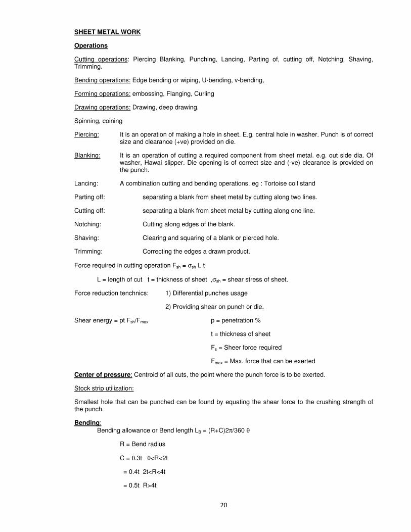
SHEET METAL WORK
Operations
Cutting operations: Piercing Blanking, Punching, Lancing, Parting of, cutting off, Notching, Shaving, Trimming.
Bending operations: Edge bending or wiping, U-bending, v-bending,
Forming operations: embossing, Flanging, Curling
Drawing operations: Drawing, deep drawing.
Spinning, coining
Piercing: It is an operation of making a hole in sheet. E.g. central hole in washer. Punch is of correct size and clearance (+ve) provided on die.
Blanking: It is an operation of cutting a required component from sheet metal. e.g. out side dia. Of washer, Hawai slipper. Die opening is of correct size and (-ve) clearance is provided on the punch.
Lancing: A combination cutting and bending operations. eg : Tortoise coil stand
Parting off: separating a blank from sheet metal by cutting along two lines.
Cutting off: separating a blank from sheet metal by cutting along one line.
Notching: Cutting along edges of the blank.
Shaving: Clearing and squaring of a blank or pierced hole.
Trimming: Correcting the edges a drawn product.
Force required in cutting operation Fsh = σsh L t
L = length of cut t = thickness of sheet ,σsh = shear stress of sheet.
Force reduction tenchnics: 1) Differential punches usage
2) Providing shear on punch or die.
Shear energy = pt Fsh/Fmax p = penetration %
t = thickness of sheet
Fs = Sheer force required
Fmax = Max. force that can be exerted
Center of pressure: Centroid of all cuts, the point where the punch force is to be exerted.
Stock strip utilization:
Smallest hole that can be punched can be found by equating the shear force to the crushing strength of the punch.
Bending:
Bending allowance or Bend length LB = (R+C)2π/360 θ
R = Bend radius
C = θ.3t θ<R<2t
= 0.4t 2t<R<4t
= 0.5t R>4t

Bending force = 0.33Wt2 σt/L Edge bending
= 0.66 wt2 σt/L U - Bending
= 1.2 wt2σt/L V – Bending
Where W = Width of sheet mm
T = thickness of sheet mm
L = Length effected due to bending mm, = Rd+t+Rp
Rd = radius on die (Bend radius)
Rp = radius on punch
σt = tensile yield strength
Ratio for bending force for edge, U and V Bending is 1:2:4
Drawing operation: It is a manufacturing method for cylindrical and non-cylindrical shell.
Blank diameter required D=√d2+4dh (for cylindrical shells) where D = dia. of shell
Blank surface area = shell surface area.
Drawing load FD=[σu+σy/2) πdt.
Draw ratio = D/d
Deep drawing: Redraw operations
Diameter reduction: I draw 40%, II draw 25% on I draw
III draw 15% on II draw, IV draw 10% on III draw
Types of press Tools Piercing tool, Blanking tool, compound tool, Bending tool, forming tool, combination tool, progressive tool, drawing tool, redrawing tool, inverted tool, fine blanking tool. Types of presses: Open Bank inclined presses, Simple action, Double action, Triple action presses
Press Tool elements: Punch, die, Bottom Bolster, Top holster, Stripper, thrust plate, punch plate, guide bushes, guide pillars, stock guides, stoppers, ejectors, shedders, strippers bolts, dowel pins, shank.

MEASUREMENTS & INSPECTION
LIMITS:
The component cannot be produced exactly to the correct size or designed dimensions, due to various reasons like manual errors, machine errors, material errors, environmental conditions, measurement errors. If at all to be produced, it will be so costly and not economical. In this regard if a small variation is permitted on component dimensions, (for producing it) with out effecting function, cost of manufacturing will decrease. This variation on dimensions, which will set LIMIT on higher side and on lower side , called Limiting dimensions.
TOLERANCE:
Magnitude of permissible variation of a dimension or other measured or control criterion from the specified value.
Tolerance is the difference between upper limiting size and lower limiting size of the component.
Accuracy decreases as tolerance increases.
Types of tolerances:
Unilateral tolerance: variation is expressed on only one side of the basic dimension. E.g; d-a,-b
Bilateral tolerance : variation is expressed on both sides of the basic dimension. E.g; d +a,-b
Accumulation of tolerance : L+g,-h
=L1+a-b
+L2+c-d
+L3+e-f
g = a+c+e , h = b+d+f
Compound tolerance: Effect of tolerance of one feature on another.
Form tolerance :
Geometry tolerance :
Interchangeability :
Selective assembly :
Conditions for fixing the limits :
a)Functional requirements b)Interchangeability c)Economics
INDIAN STANDARDS (IS 919-1963)
18 grades of fundamental tolerances, IT0,IT01,IT1,IT2,…IT16.
25 grades of fundamental deviations, A,B,C,……Za,Zb,Zc
Allowance :An dimentional difference between two mating parts.
Fits : Degree of tightness or looseness between two mating parts
: Relation between two assembled parts resulting from the difference between their sizes before assembly is called fit.
Types of Fits:
i) Clearance fits : a to h basic size shafts with H hole
ii) Transition fits : j to n basic size shafts with H hole
iii)Interference fits : p to zc basic size shafts with H hole

Hole basis system is selected, as its fundamental deviation is zero.
Values of IT grade tolerances:
IT6 = 10 i, IT11= 100i, IT16= 1000i i= 0.45 (D)1/3
+0.001D
IT01=0.3+0.008D, IT0= 0.5+0.012D, IT1=0.8+0.02D
IT2 to IT4 are scaled approximately geometrically between IT1 to IT5 D = geometric mean of diameter steps.
Fundamental deviation :Upper or lower deviation which is close to zero line (basic size or nominal size)
Basic shaft: upper deviation is zero e.g, h
Basic hole: lower deviation is zero e.g, H
Max.size of shaft or min. size of hole =nominal size +Fundamental deviation.
Max. size of Hole = min. size of hole + IT grade tolerance
Min. size of shaft = max.size of shaft + IT grade tolerance
To inspect the components for their limiting sizes, gages are used. Gages: Plug gages (for checking holes)
: Ring/Snap gages (for checking shafts) : Go gages (Maximum material condition (MMC) to check all the features except least material condition : No go gages [to check only least material condition(LMC)] Gage design: 1) Gage makers tolerance = 10% of work tolerance 2) Wear allowance = 10% gage tolerance (only on go gages) Types of gages: Position gages, contour/profile gages, combined limit gages, workshop
gages, inspection gages, Master gages. Standards of Measurements:
Line standards: Yard, Meter etc. End standards: Slip gages, gap gages, end of micro meter anvils etc.
Wave length standards: Wave length of mono chromatic light which is material and invariable unit of length.
Standard length relative to meter is expressed in terms of the wave length of red radiation of cadmium.
Measurements: Linear measurements: Steel rule, calipers, divider, slip gages, surface plates Angle measurements: Spirit level, sine bar, Bevel gages, angle gages etc.. are used for external taper. Internal angle is measured by balls, or balls and rollers. Surface finish measurement Finish or roughness measurement: Ten point height of irregularities (RZ) is defined as the average difference between the five highest peaks and five deepest valleys within the sampling length measured from a line, parallel to the mean line and not crossing the profile. RZ = [R1+R3+R5+R7+Ra] – [R2+R4+R6+R8+R10]/5 Root mean square roughness
Ra = 1/L√ oL h
2dx
Center line average (CLA) value of roughness = Σh/n

Methods of measuring surface finish 1) Touch inspection 2) visual inspection 3) scratch inspection 4) Microscopic inspection 5) surface photographs 6) Micro-interferometer 7) Wallace surface dynamometer 8) Reflected light intensity Direct instrument measurements: 1) Tomlinson surface meter (smoked glass) 2) Taylor – Hobson Taly surf Roughness will be indicated by grades and symbols ----------------------------------------------------------------------------------------------------------------
Grade Roughness value (µm) Symbol Mfg.method ---------------------------------------------------------------------------------------------------------------
N12 50 ∼ Machining --------------------------------------------------------------------------------------------------------------- N11 25 grinding/finish maching
∇ Broaching N10 12.5 ---------------------------------------------------------------------------------------------------------------- N9 6.3
N8 3.2 ∇∇ grinding/Reaming, Broaching N7 1.6 ----------------------------------------------------------------------------------------------------------------- N6 0.8
N5 0.4 ∇∇∇ Honing N4 0.2 Lapping ------------------------------------------------------------------------------------------------------------------ N3 0.1 Lapping
N2 0.05 ∇∇∇∇ Buffing N1 0.025 Electro plating ------------------------------------------------------------------------------------------------------------------- Thread measurement:
Types of threads: BSW (55o), AS (60
o), B.A (47.5
o), Buttress (45
o)
ACME (29o) square (90
o) Metric (60
o), Knuckle, Unified
Screw thread terminology:
External thread, internal thread, multiple-start thread, axis of thread, right/left hand thread, form of thread, craft of thread, Root of thread, flank, Angle, Pitch, Lead angle, depth of thread, axial thickness, fundamental triangle, addendum, dedendum, truncation, Major diameter, Minor diameter, Effective or pitch diameter.
Errors in Threads
Errors may occur in any five of the elements.
1) Major diameter 2) Minor diameter 3) Effective diameter 4) Pitch of thread form
5) Angle of thread form errors in major and minor dia. will cause interference with mating thread.
Effective diameter measurement:
1) Micro meter method.
2) Two wire method or three wire method
Two-wire method
E = T+P Where E = Effective diameter
T = Dimension under the wires
= (M-Z d)

M = dimension over the wires
d = diameter of the best wire
P = It is a value which depends up on the Dia. of wire and pitch of the thread
P = P/2[ Cot x/2 – d(Cosec (x/2)-1)]
P = Pitch of the thread
X = angle of the thread
Three – wire method
M=E + d(1+Cosec x/2) – p/2 cot x/2
For tapered threads:
E = (M-d) Sec h + Cot x/2 / 2n – cosec x/2
h = half the angle of toper
n = no.of threads per inch.
Best wire size d = p / 2cos(x/2)
COMPARATORS:
A comparator works on relative measurements, i.e to say, it gives only dimensional differences in relation to a basic dimension. These are used for only linear measurements.
Characteristics of Comparators:
1) Must be robust in design and construction 2) Provision for maximum compensation for temp. effects to be given. 3) Used in mass production 4) Used as lab standards, from which working or inspection used gages are set and
correlated, (calibrated). 5) For inspections newly purchased gages. 6) Used in selective assembly
Types of comparators
1. Mechanical comparators. a) Dial indicators b) Jhonson Mikro kator c) Reed type mech. Comparator d) Sigma comparator
2. Mechanical – optical comparators a) Ziess-Ultra optimeter b) Ziess opto test comparator
b) Newall OMS horizontal optimeter d) Eden-Rolt millionth Comparator 3. Electrical comparators: a) L V D T 4. Electronic comparators. 5. Pneumatic comparators. a) Solex pneumatic gage b) Differential comparator 6. Fluid displacement comparator 7. Optical projectors 8. Multi check comparators 9. Automatic gauging machines. Alignment tests:
Hardness testing:
Brinnel Hardness tester, Vickers Hardness tester, Rock well Hardness tester
Knoop hardness tester, Scaloriscope

C I M
Automation
Def: Automation is a technology concerned with the application of mechanical, electronic, and computer-based systems to operate and control production.
Types of automation
Fixed automation for mass production. I.e. for product lay out. Programmable automation applied for process lay out i.e. for batch prod. Flexible automation applied for job order production.
Functions of manufacturing:
Processing, assembly, material handling system, inspection & testing, control.
Automation Strategies:
Specialization of operations, combined operations, simultaneous operations, integration of operations, increased flexibility, material handling & storage, on-line inspection, process-control & optimisation, plant operation control, CIM.
Numerical control: It uses a program of instruction that is electronically transmitted to the production equipment to regulate its function and operation.
Basic concepts of NC : Program, MCU, processing equipment
Co-ordinate system : Absolute method, incremental method of Dimensioning (parallel dimensioning)
(chain dimensioning)
Machine motions : Fixed zero, Floating zero
Types of NC : 1) Point to Point (PTP) NC (x,y)
2) Straight cut NC dx/dt or dy/dt
3) Contouring NC dx/dt and dy/dt
- Closed loop NC open loop NC
(with feed back & control)
Accuracy and repeatability
Interpolation schemes: Linear, circular, Helical, Parabolic, Cubic
NC machine tool operations: ATC, AWC, Pallet shuttle, machining centers, electrical wire wrap machine, assembly, drafting, flame cutting, welding etc..
Economics of NC: Reduced production time, reduce fixturing, reduced lead time, manufacturing flexibility, easier changes in design, management functions, non optimal speeds and feeds.
Problems with NC: Part program mistakes, fragile punched tape, Un reliable tape reader, controller, management functions, Non optimal speeds & feeds.
Drive motors: Stepper motor with individual axis drive.
DNC: Direct Numerical control.
Features: Central computer with Bulk memory, Telecom lines, Machine tools.
Advantages of DNC: Time sharing, higher computational capability, Remote computer location, improved reliability, elimination of hard wired controller, cutter compensation, etc.

CNC:
Def:
Differences between CNC & DNC:
CNC features:
Advantages:
NC part programming: Punched tape, magnetic tape, floppy disc, compact disc etc.. Bit, byte, character, word, Block.
NC words: 1. Sequence Number words (N-words): Used to identify the block e.g.N005 2. Preparatory word (G-Words): Used to prepare controller for instruction that are to follow. e.g. G02
3. Coordinate (X,Y,Z) words : gives the coordinate position of the tool
4. Feed-rate (F-Word): Specifies the feed rate in a machining operation in inches/min. or mm/min. e.g. F 30
5. Cutting speed (S-Word): Specifies the rate at which the spindle rotates. Rev/min. e.g. S684
6. Tool selection (T-Word): Specifies the tool to be used in the operation. e.g. T05
7. Miscellaneous functions (M-Word): Auxiliary functions will be specified e.g. M07
Tape Formats:
1) Word address format 2) Tab sequential format 3) Fixed block format
Methods of NC part programming:
1) Manual part programming (G-code, M-code) 2) Computer assisted part programming (APT, ADAPT, EXAPT, SPOT, SPLIT, etc..)
3) Manual date Input
4) N.C.P.P. using CAD/CAM
5) Computer automated part programming.
Programming with APT consists of 4 types of statements.
1) Geometric statements 2) Motion statements 3) Post processor statements 4) Auxiliary statements.
Material handling systems:
In industry about 30% of product cycle time is consumed in material handling. Material handling equipment must be automated in correlation with NC machines so as to reduce idle time. Material handling equipment design depends on
(i) the type of material to be handled (a) gas (b) liquid (c) solid
(ii) The type of lay out (a) Product lay out (b) Process lay out
Automated storage and retrieval system:
Principle: First in goods must be first out.

Group technology:
It is a manufacturing philosophy in which similar parts are identified and grouped together to take advantages of their similarities in manufacturing and /or design.
Components are divided in to part families, then classification and coding will be done by any of the two systems (i) OP1TZ system (ii)Multi class system
Machine cell design can be achieved by GT.
Benefits of GT:
Flexible Manufacturing systems: [FMS] FMS integrates many of the concepts and technologies in to one highly automated production system. The technologies include: Flexible automation, group technology, CNC machine tools, Automated material handling between machines, DNC, storage and material handling.
FMS and FMC.
FMS layout configurations: In line, loop, ladder, open field, Robot centered cell.
Fundamentals of CAD:
Computer aided manufacturing (CAM) consists manufacturing, planning, manufacturing control, CAPP, MRP.
Computer Integrated Manufacturing System [CIM]
CIM encompasses the entire range of product development and manufacturing activity with all functions being carried out with the help of dedicated software packages.
CIM stands for holistic and methodological approach to the activities of the enterprise in order to achieve vast improvement in its performance. The methodological approach is applied to all activities from the design of the product to customer support in an integrated way, using various methods, means and techics in order to achieve production improvement, cost reduction, fulfillment of scheduled delivery date, quality improvement and total flexibility in mfg. System. CIM encompasses the whole lot of enabling technologies including TQM, business process, re engineering, concurrent engineering, work flow automation, ERP and flexible manufacturing.
Eg: FMC, robotized work cells, flexible inspection cells.
CIM makes use of capabilities of the digital computer for manufacturing.
e.g. (i) Variable and programmable automation
(ii) Real time optimization
CIM soft ware comprises computer programs to carry out the following functions.
MIS, sales, marketing, finance, DBM, modeling & design, analysis, simulation, communications, monitoring, production control, manufacturing area control, Job tracking, Inventory control, material handling, process planning, automations, quality management etc..
Major elements of CIM 1) Marketing 2) Product design 3) Planning 4) Purchase 5) Manufacturing engg. 6) factory automation hardware 7) Ware housing 8) Finance 9) Management information. Sequential Engineering: The traditional product development cycle is sequential. It includes product design, development of mfg. Process and supporting quality and testing activities, all carried out one after another.

Concurrent Engineering: Concurrent engineering or simultaneous engineering is a methodology of restricting the product development activity in an organization using a cross functional team and is a technic adapted to improve the efficiency of product and reduce the product design cycle time. This is also called parallel engineering.
Concurrent engineering gives marketing and other groups, the opportunity to review the design during the modeling, proto typing (RPT), and soft tooling phases of development.
Characteristics concurrent Engineering:
-- Integration of product development, process development, and logistic support.
-- Closer attention of the needs of customer and new technologies.
-- Continuous review of design and development process.
Rapid proto typing.

METAL CASTING
1. In green sand moulding process, uniform ramming leads to
a) Less chance of gas porosity. b) Uniform flow of molten metal into the mould cavity. c) Greater dimensional stability of casting. d) Less sand expansion type of casting defect.
2. Match A. Slush casting 1) Turbine blade
B. Shell moulding 2) Machine tool bed
C. Dry sand moulding 3) Cylinder block
D. Centrifuged casting 4) Hollow castings like Lamp & shades 5) Rain water pipe 6) CI shoe brake
A) 4 1 3 5 B) 1 4 3 5 C) 4 1 5 3 d) 3 5 1 4
3. Centrifugally cast products have
a) large grain structure with high porosity b) Fine grain structure with high density c) Fine grain structure with low density d) Segregation of slag towards the outer skin of the casting
4. Matching
A) Investment casting 1) Turbine rotors
B) Die casting 2) Turbine blades
C) Centrifuged casting 3) Connecting rods
D) Drop forging 4) GI pipes
E) Extrusion 5) CI Pipes
F) Shell moulding 6) Carburettor body
(A) 1 6 5 3 4 2 (B) 165324 (C) 615324 (D) 163542
5. Light impurities in the molten metal are prevented from reaching the mould cavity by providing a
a) Stainer b) button wall c) skim bob d) all the above
6. Chills are used in moulds to
a) achieve directional solidification b) reduce the possibility of blow holes c) reduce freezing zone d) Smoothen metal flow for reducing spatter
7. Match
A) Sand casting 1) symmetrical and circular Shapes only
B) Plaster mould casting 2) Parts have hardened Skins and soft interior
C) Shell mould casting 3) Minimum post casting Processing
D) Investment casting 4) Parts have a tendency to warp
6) Parts have soft skin and hard interior 7) Suitable only for non Fe metals
a) 4 6 5 3 b) 1 3 5 6 c) 6 4 5 3 d) 2 4 6 1
8. Which of the following materials requires the largest shrinkage allowance, while making a pattern for casting?
a) Al b) Brass c) CI d) plain carbon steel
9. Disposable patterns are made of
a) wood b) rubber c) metal d) polystyrene

10. Shrinkage allowance on pattern is provided to compensate for shrinkage when
a) the temp of liquid metal drops from pouring to freezing temp. b) the metal changes from liquid to solid state at freezing temp. c) the temp of solid phase drops from freezing to room temp. d) the temp. of metal drops from pouring to room temp.
11. The height of the down sprue is 175mm and its cross sectional area at the base 200mm2. The cross
sectional area of the horizontal runner is also 200 mm2. Assuming no losses, indicate the correct
choice for the time (in seconds) required to fill a mould cavity of 106 mm
3 volume (use g=10m/sec
2)
a) 2.67 b) 8.45 c) 26.72 d) 84.50
12. The primary purpose of a sprue in a casting mould is to
a) feed the casting at a rate consistent with the rate of solidification b) act as a reservoir for molten metal c) feed molten metal from thee pouring basin to the gate. d) Help feed the casting until all solidification taken place.
13. In centrifuged casting, the impurities are
a) Uniformly distributed b) Forced towards the outer surface c) Trapped near the mean radius of the casting d) Collected at the center casting
14. Hardness of green sound a increases with
a) increase in moisture content beyond 6% b) increase in permeability c) decrease in permeability d) increase in both moisture content and permeability
15. With a solidification factor of 0.97 x 10⁶ s/m
2, the solidification time (in seconds for a spherical
casting of 200 mm diameter
a) 539 b) 1078 c) 4311 d) 3233
16. Sprues are tapered to
a) reduce in aspiration b) improve casting yield
c) help in faster rate of mould filling d) separate slag from molten metal
17. The permeability of moulding sand was determined using a standard AFS sample by passing 2000CC of air at a gage Pr. Of 10g/cm
2. If the time taken for the air to escape was 1 min, the permeability no.
is… a) 712.4 b) 100.2 c) 75.3 d) 50.1
18. In a non-pressurized gate system, an Al-alloy is poured at a flow rate of 0.8 x 10⁻³
m3/min. through a
sprue with a base cross sectional area of 400 mm2. If the friction losses a in the sprue are neglected,
the height of the sprue is
a) 200 mm b) 150 mm c) 250 mm d) 300 mm
19. C lay binder used in the preparation of foundry moulding sand is
a) Illite b) Kaolin c) Bentonite d) Fuller’s earth
20. Saw dust is added to sodium silicate bonded CO2 gassed sand to improve its:
a) collapsibility b) flowability c) permeability d) comp. Strength

21. Castings are designed with rounded edges and corners so as to:
a) increase the overall strength of the casting b) improve toughness c) prevent mould erosion by metal stream d) prevent plane of weakness where the columned grains join
22. Match
A) Automobile piston in Al-alloy 1. Gravity die casting
B) Engine crank shaft in
Spheroid graphite iron 2.Precision investment Casting
C) Carburetor housing in 3. Sand casting
Al-alloy 4.Precision die casting
5. Centrifugal casting
a) 1 3 4 b) 1 2 3 c) 2 3 4 d) 1 3 5
23. Die penetrant test is suitable for testing weld/casting defect (s) such as
A) Overlap, slag B) inclusions, incomplete
C) Penetration, surface cracks D) Cracks, porosity
24. Compared to permanent mould casting, pressure die casting deals with casting metals of relatively ________Melting point and provides _______ production rate.
a) high / low b) low / high c)high / high d) low / low
25. Bentonite is a commonly used bonding material for dry sand cores (T/F).
26. According to chevron rule, the solidification time of casting is proportional to (Volume/Surface area)n
where n equals.
a) 0.5 b) 1 c) 2 d) some value based on the mould material
27. Shell moulding is an investment casting process (T/F)
28. The contraction allowance on the pattern is provided to take care of
a) Contraction of the solid metal from solidification temp. to room temp. b) Shrinkage of the liquid metal from pouring temp. to solidification temp. c) Shrinkage during solidification d) Shrinkage in the liquid and solid state.
29. Negative allowance is provided on the pattern to take of care of
a) Distortion in the castings b) Ease of pattern with drawn c) Surface finish d) contraction of metal
30. Shell moulding process used following binder.
a) linseed oil b) thermoset resin
c) sodium silicate d) ethyl silicate
31. The advantage of a pressurized grating system is that
a) Casting yield is higher b) castings are free from blow holes
c) Castings are free from sand inclusions d) Castings are free from dross inclusions

32. The advantage of hot chamber die casting process over cold chamber process is
a) Higher pressure can be used to obtain better metal compaction. b) Higher melting metals can be cast. c) Thinner sections can be obtained d) Higher production rates can be obtained.
33. The solidification time (t) of casting can be estimated in terms of its volume (v) and area (A) by using the following eqn.
A) t = K V/A B) t = K(V/A)1/2
C) t = K(A/N)1/2
D) t = K(V/A)2
34. Hot tears occur in casting when
A) Differential expansion occurs in castings during heat treatment.
B) Small droplets of metal trickle down, freeze and stick to the casting surface.
C) Casting crack during later stages of solidification due to resistance to shrinkage.
D) Improper contraction allowances are given on the pattern.
35. In order to avoid center line shrinkage in castings, steep positive thermal gradients are
produced by use of -- at the moulds end. (Ans: Chills)
36. A riser should always have its modulus (V/A) ratio -- than that of the casting for effective feeding.
37. Coal dust is added to moulding sounds for improving of the casing.
a) Surface finish b) collapsibility c) hot strength d) dry strength
38. Magnetic particle inspection, under properly controlled conditions, can detect internal flaws (T/F).
39. Misrun is a casting defect which occurs due to
A) Very high pouring temp. of the metal
B) In sufficient fluidity of the molten metal
C) Absorption of gases by the liquid metal
D) Improper alignment of the mould flasks
40. Hardness of green sand mould increases with
A) increase in moisture content beyond 6% B) Increase in permeability
C) Decrease in permeability
D) Increase in both moisture content and permeability
41. Which one of the following is NOT a property of sand mold?
A) Permeability B) Collapsibility C) Strength D) Fluidity
42. Proper gating design in metal casting
P) Influences the freezing range of melt
Q) compensates the loss of fluidity of the melt R) Avoids misruns
S) Facilitates top feeding of the melt
A) P,R B) Q,S C) R,S D) P,S

43. Process Mold Making technique
P. Green sand moulding 1. Pouring
Q. Shell moulding 2. Dipping
R. Investment moulding 3. Compaction
S. Ceramic moulding 4. Resin bonding
A) P2 Q1 R4 S3 B) P1 Q3 R2 S4 C) P3 Q4 R2 S1 D) P4 Q2 R3 S1
44. A gating ratio of 1:2:4 is used to design the gating system for magnesium alloy casting. This gating
ratio refers to the cross section areas of the various gating elements as given below.
1. Down sprue 2. Runner bar 3. In gates
The correct sequence of the above elements in the ratio 1:2:4
a) 1,2 & 3 b) 1,3 & 2 c) 2,3 & 1 d) 3,1 & 2
45. Matching
List-I List-II
A. Hollow structures 1. Centrifuged casting
B. Dentures 2. Investment casting
C. Al-alloy pstons 3. Slush casting
D. Rocker arms 4. Shell moulding
5. Gravity die casting
a) 3245 b) 1345 c) 1234 d) 3254
46. The most preferred process for casting gas turbines blades is
a. die moulding b. shell moulding c. investment casting d. sand casting
47. Die penetrant method is generally used to locate
a. core defects b. surface defects c. superficial defects d. temporary defects
48. A) In a mould, a riser is designed and placed so that the riser will solidify after the casting has solidified (True/False)
R) A riser is a reservoir of molten metal which will supply molten metal where a shrinkage
cavity would have occurred (True/False)
49. Which of the following materials can be used for making patterns?
1. Al 2. iron /steel 3. mercury 4. lead
a. 1,2,4 b. 1,3,4 c. 2,3,4 d. all
50. Distinguish between internal chills and chaplets. What is common between both
51. Distinguish between permeability and porosity
52. Moulding sand is different from the river sand give your comments in support of the above statement and also indicate the properties of moulding sand which are desirable for making sound castings. How do you determine 4 of these properties in laboratory
53. Which one of the following materials will require the largest size of riser for the same size of casting?
a. Al b. CI c. steel d. copper
54. Directional solidification in a casting can be improved by using a. chills and chaplets b. chills and padding

c. chaplets and padding d. chills, chaplets and padding
55. A) Al-alloys are cast in hot chamber die casting machine (True/False) B) Al alloys require high melting when compared to zinc alloys (True/False)
56. What is soleroscope?
57. How sand cores are supported?
58. Name 5 of casting defects. How they are gauged and what are the remedies?
59. What is “lost wax” method
60. Consider the following in gradients used in moulding.
1. dry silica sand 2. clay 3. phenol formaldehyde 4. sodium silicate
a. 1 & 2 b. 1 & 3 c. 2 & 3 d. 2 & 4
61. Which of the following methods are used for obtaining directional solidification for riser design.
1. suitable placement of chills 2. suitable placement of chaplets
3. employing padding
a. 1 and 2 b. 1 and 3 c. 2 and 3 d. all
62. Misrun is a casting defect which occurs due to
a. very high pouring temp. of the metal b. insufficient fluidity of the molten metal
c. absorbtion of gases by mould casting
63. Which of the following are correctly matched 1. pit moulding – for large jobs
2. investiment moulding – lost wax process
3. plaster moulding – mould prepared with gypsum
a. 1, 2, 3 b. 1 and 2 c. 2 and 3 d. none
64. Which of the following pairs is not correctly matched a. Al-alloy – pressure die casting
b. Jwellary – lost wax method
c. large pipes – centrifugal casting
d. large bell – loam moulding
a). a , b , c , d b).a , b, c c).b , c , d d) a, c, d
65. What are vents and chills in mould?
66. A sand casting mould assembly is shown in the fig. The elements masked A and B are respectively.
a. sprue and riser
b. ingrate and riser
c. drag and runner
d. riser and runner
67. Which of the following are the requirements of an ideal gating system?
1. the molten metal should enter the mould cavity with as high velocity as possible
2. it should facilitate complete filling of the mould cavity
3. it should be able to prevent the absorption of air or gases from the surrounding on the molten metal
while flowing through it

a. 2 and 3 b. 1 and 3 c. 1 and 2 d. all
68. A spherical drop of molten metal of radius 2mm was found to solidify in 10 seconds. A similar drop of radius 4mm would solidify in seconds.
a. 14.14 b. 20 c. 28.3 d. 40
69. Poor machinability of centrifugal CI pipe is due to
a. chilling b. segregation c. dense structure d. high mould rotation speed
70. The best shape of a sprue in sand casting is an inverted frustum of a cone ___ why?
71. In solidification of metal during casting, compensation for solid contraction is
a. provided by the oversize pattern b. achieved by properly placed risers
c. obtained by promoting directional solidification d. made by providing chills
72. Matching
Types of casting working principle
A. Die casting 1. molten metal is forced into the die under pressure
B. Centrifugal casting 2. axis of rotation does not coincide with axis of mould
C. centrifuging 3. metal solidifies when mould is rotating
D. continuous casting 4. continuously pouring the molten metal into mould.
a. 1,3,2,4 b. 1,2,3,4 c. 4,2,3,1 d. 4,3,1,2
73. Matching
Products Material
A. Die casting 1. Phenol formaldehyde
B. Shell moulding 2. CI pipes
C. CO2 moulding 3. Non-ferrous alloys
D. Centrifugal casting 4. Sodium silicate
a. 1,3,4,2 b. 3,1,4,2 c. 2,4,3,1 d. 4,2,3,1
74. List 4 parameters to be considered in the gating design of moulds.
75. Give step-by step procedure for the cold chamber die-casting process. Also discuss the advantages and limitations of hot chamber processes.
76. The main purpose of chaplets is
a. to ensure directional solidification b. to provide efficient venting
c. for aligning the mold boxes d. to support the core
77. Scab is a. sand casting defect b. machining defect
c. welding defect d. forging defect
78. A 100mm thick steel bar is to be cast with two correctly spaced top risers of adequate feeding capacity. Assuming end effect without chill, what should be the theoretical length of bar?
a)96mm b)132mm c) 192mm d)156mm
79. Grey CI blocks 200x100x10 mm are to be cast in sand moulds. Shrinkage allowance for pattern making is 1% The ratio of volume of pattern to that of casting will be

a) 0.97 b)0.99 c)1.01 d)1.03
80. with a solidification factor of 0.97x 10⁶
s/m2
,the solidification time (in seconds) for a spherical casting of 200mm diameter is
a) 539 b)1078 c)4311 d)3233
81. Misrun is a casting defect which occurs due to (A) Very high pouring temperature of the metal (B) Insufficient fluidity of the molten metal (C) Absorption of gases by the liquid metal (D) Improper alignment of the mould flasks
82. Gray cast iron blocks 200 x 100 x 10 mm are to be cast in sand molds. Shrinkage allowance for
pattern making is 1%. The ratio of the volume of pattern to that of the casting will be
(a) 0.97 (b) 0.99 (c) 1.01 (d) 1.03
83. A mould has a downsprue whose length is 20cm and the cross sectional area at the base of the
downsprue is 1 cm2. The downsprue feeds a horizontal runner leading into the mould cavity of
volume 1000cm3. The time required to fill the mould cavity will be
(a) 4.05 s (b) 5.05 s (c) 6.05 s (d) 7.25 s
84. An expendable pattern is used in
(a) Slush casting (b) squeeze casting
(c) Centrifugal casting (d) investment casting
85. In a sand casting operation, the total liquid head is maintained constant such that it is equal to the
mould height. The time taken to fill the mould with a top gate is tA. If the same mould is filled with a
bottom gate, then the time taken is tB . Ignore the time required to fill the runner and frictional
effects. Assume atmospheric pressure at the top molten metal surfaces. The relation between tA
and tB
(a) tB = tA (b) tB = 2 tA (c) ) tB = tA /2 (d) ) tB = 2 tA
86. Volume of a cube of side ‘l’ and volume of a sphere of radius ‘r’ are equal. Both the cube and the
sphere are solid and of same material. They are being cast. The ratio of the solidification time of
the cube to the same of the sphere is
(a) (4/6)3(r/l)
6 (b) (4/6) (r/l)
2 (c) (4/6)
2 (r/l)
3 (d) (4/6)
2 (r/l)
4
87. A 200mm long down sprue has an area of cross-section of 650 mm2 where the pouring basin
meets the down sprue (i.e. at the beginning of the down sprue). A constant head of molten metal is
maintained by the pouring basin. The molten mar=tel flow rate is 6.5 x 105 mm
3/s. Considering the
end of down sprue to be open to atmosphere and an acceleration due to gravity of 104 mm/s
2 , the
area of the down sprue inmm2 at its end (avoiding aspiration effect) should be
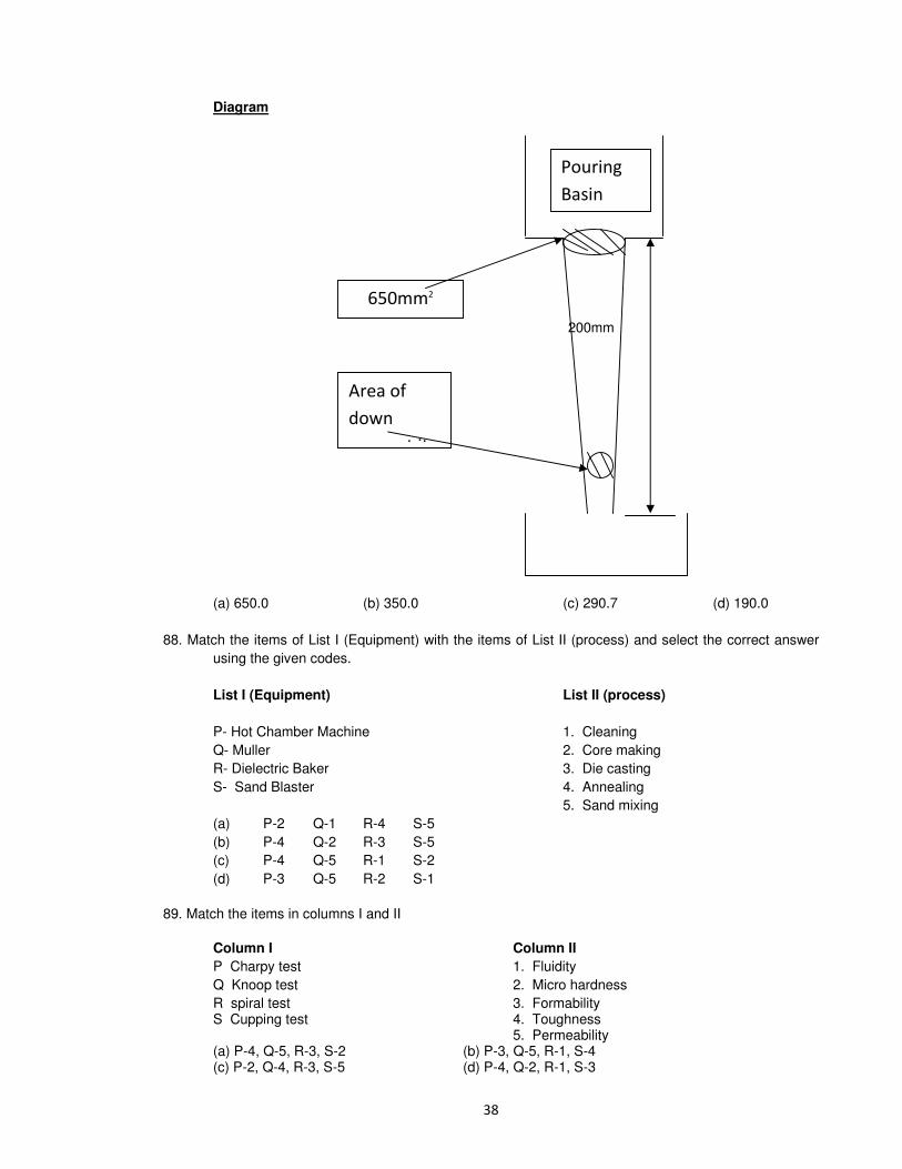
Diagram
200mm
(a) 650.0 (b) 350.0 (c) 290.7 (d) 190.0
88. Match the items of List I (Equipment) with the items of List II (process) and select the correct answer
using the given codes.
List I (Equipment) List II (process)
P- Hot Chamber Machine 1. Cleaning
Q- Muller 2. Core making
R- Dielectric Baker 3. Die casting
S- Sand Blaster 4. Annealing
5. Sand mixing
(a) P-2 Q-1 R-4 S-5
(b) P-4 Q-2 R-3 S-5
(c) P-4 Q-5 R-1 S-2
(d) P-3 Q-5 R-2 S-1
89. Match the items in columns I and II
Column I Column II
P Charpy test 1. Fluidity
Q Knoop test 2. Micro hardness
R spiral test 3. Formability S Cupping test 4. Toughness 5. Permeability
(a) P-4, Q-5, R-3, S-2 (b) P-3, Q-5, R-1, S-4 (c) P-2, Q-4, R-3, S-5 (d) P-4, Q-2, R-1, S-3

90. Match List I (Types of casting) with list II (Working principles) and select the correct answer:
A. Die casting B. Centrifugal casting C. Centrifuging D. Continuous casting
List II
1. Molten metal is forced into the die under pressure
2. Axis of rotation does not coincide with axis of mould
3. Metal solidifies when mould is rotating
4. Continuously pouring molten metal into mould
Codes; A B C D
a. 1 2 3 4 b. 4 3 2 1 c. 1 2 3 4 d. 4 2 3 1
91. Match List I (process) with List II
(products/materials) and select the correct answer:
List I
A. Die casting B. Shell molding C. CO2 molding D. Centrifugal casting
List II
1. Phenol formaldehyde 2. C.I. pipes 3. Non-ferrous alloys 4. Sodium silicate
Codes; A B C D
a. 1 3 4 2 b. 3 1 4 2 c. 3 1 2 4 d. 1 3 2 4
92. Assertion (A): In CO2 casting process, the moule or core attains maximum strength.
Reason (R): The optimum gassing time of CO2 through the mould or core forms Silica Gel which imparts sufficient strength to the mould or core.
a. Both A & R are true & R is the correct explanation of A
b. Both. A and R are true but R is NOT the correct explanation of A
c. A is true but R is false
d. A is false but R is true
93. The main purpose of chaplets is
a. to ensure directional solidification b. to provide efficient venting
c. for aligning the mold boxes d. to support the cores
94. Scrab is a
a. sand casting defect b. maching defect c. welding defect d. forging defect
95. A gatting ratio of 1 : 2 : 4 is used to design the gating system for magnesium alloy casting. This gating ratio to the cross section areas of the various gating elements as given below :
1. Down sprue 2. Runner bar 3. Ingates
The correct sequence of the above elements in the ratio 1 : 2 : 4 is
a. 1, 2 and 3 b. 1, 3 and 2 c. 2, 3 and 1 d. 3, 1 and 2
96. Match List I (Products) with List II (Casting process) and select the correct answer :
List I

A. Hollow statues B. Dentures C. Aluminium alloy pistons D. Rocker arms
List II
1. Centrifugal Casting 2. Investment Casting 3. Slush Casting 4. Shell Moulding 5. Gravity Die Casting
A B C D
a. 3 2 4 5 b. 1 3 4 5 c. 1 2 3 4 d. 3 2 5 4
97. In gating system design, which one of the following is the correct sequence in which choke area, pouring time, pouring basin and sprue sizes are calculated?
a. Choke area - Pouring time – Pouring basin - Sprue
b. Pouring basin - Sprue - Choke area - Pouring time
c. Choke area - Sprue - Pouring basin -Pouring time
d. Pouring basin - Pouring time – Choke area - Sprue
98. Which one of the following processes produces a casting when pressure forces the molten metal into the mould cavity?
a. Shell moulding b. Investment casting c. Die casting d. Continuous casting
99. The gating ratio 2 : 8 : 1 for copper in gating system design refers to the ratio of areas of:
a. Sprue : Runner : Ingate b. Runner : Ingate : Sprue
c. Runner : Sprue : Ingate d. Ingate : Runner : Sprue
100. In shell moulding, how can the shell thickness be accurately maintained?
a. By controlling the time during which the pattern is in contact with mould
b. By controlling the time during which the pattern is heated
c. By maintaining the temperature of the pattern in the range of 175°C–380°C
d. By the type of binder used
101. In which of the following are metal moulds used?
a. Greensand mould b. Dry sand mould c. Die casting process d. Loam moulding
102. Which of the following materials are used for making patterns in investment casting method ?
1. Wax 2. Rubber 3. Wood 4. Plastic
Select the correct answer using the codes given below :
a. Only 1 and 3
b. Only 2 and 3
c. Only 1, 2 and 4
d. Only 2, 3 and 4
103. Shell moulding can be used for :
a. producing milling cutters
b. making gold ornaments
c. producing heavy and thick walled casting
d. producing thin casting

104. According to Chvorinov’s equation, the solidification time of a casting is proportional to
a. V2 b. V c. 1/V d. 1/V
2
where, V = volume of casting
105. Match List - I with List – II and select the correct answer using the code given below the lists
List - I (Casting Process)
A. Die casting B. Investment casting. C. Shell moulding D. Centrifugal casting
List - II (Principle)
1. The metal solidifies in a rotating mould
2. The pattern cluster is repeatedly dipped into a ceramic slurry and dusted with refractory
3. Molten metal is forced by pressure into a metallic mould
4. After cooling, the invest is removed from the casting by pressure jetting or vibratory cleaning
Codes; A B C D
a. 2 1 3 4 b. 3 4 2 1 c. 2 4 3 1 d. 3 1 2 4
106. Consider the following statements in respect of investment castings:
1. The pattern or patterns is/are not joined to a stalk or sprue also of wax to form a tree of patterns.
2. The prepared moulds are placed in an oven and heated gently to dry off the invest and melt out the bulk of wax.
3. The moulds are usually poured by placing the moulds in a vacuum chamber.
Which of the statements given above are correct?
a. 1 and 2 only b. 1 and 3 only c. 2 and 3 only d. 1, 2 and 3
107. Which of the following are employed in shell moulding?
1. Resin binder 2. Metal pattern 3. Heating coils
Select the correct answer using the code given below
a. 1 and 2 only b. 1 and 3 only c. 2 and 3 only d. 1, 2 and 3
108. Which one of the following is the correct statement?
In a centrifugal casting method
a. no core is used b. core may be made of any metal
c. core is made of sand d. core is made of ferrous metal
109. Which one of the following is the correct statement?
Gate is provided in moulds to
a. feed the casting at a constant rate b. give passage to gases
c. compensate for shrinkage d. avoid cavities
110. Bottom gating system is sometimes preferred in casting because
a. it enables rapid filling of mould cavity b. it is easier to provide in the mould
c. it provides cleaner metal d. it reduces splashing and turbulence

111. The pattern adopted for those castings where there are some portions which’ are structurally weak and are likely to break by the force of ramming are called:
a. Loose piece pattern b. Follow board pattern c. Skelton pattern d. Single piece pattern
112. Which of the following casting processes does not/do not require central core for producing pipe?
1. Sand casting process 2. Die casting process 3. Centrifugal casting process
Select the correct answer using the code given below:
a. 1 and 2 b. 2 only c. 2 and 3 d. 3 only
113. Small amount of carbonaceous material sprinkled on the inner surface of mould cavity is called
a. Backing sand b. Facing sand c. Green sand d. Dry sand

PROBLEMS
1. How is the wax pattern mode for an investment casting and why the master pattern is made oversize?
2. The Rectangular casting of 100 x 150 x 200 mm3 with a circular hole of diameter 80 mm is to be made
in steel using a wooden pattern. Assuming only shrinkage allowance of 0.0210 mm/mm, calculate the
dimensions of the pattern.
3. For the casting in the above problem, if the pattern is to be made of Aluminum calculate the
dimensions of wooden pattern which is to be used for making the aluminum pattern. Shrinking
allowance for Al. is 0.013 mm/mm also provide draft allowance for the wooden pattern.
4. A cast iron cylinder of 450 mm out side diameter, 75mm inside diameter and 150 mm long is to be
casted by sand casting. Design the requisite pattern assuming that the internal hole is to be finished by
machining.
5. A master Aluminum pattern is to be cast using a wooden pattern for a hollow cylindrical piece with a
flange of width 50mm and diameter 250mm. The cylindrical portion is 200mm long with an outer
diameter of 150mm and an inner diameter of 75mm. If the face of the flange is to be machined, Design
the wooden pattern.
6. Draw a dimensional sketch of the pattern required for the manufacture of hollow cylindrical castings in
steel including the allowances provided.
Cylinder size after machining all around OD = 150mm
ID = 100 mm
Length = 150mm
Shrinkage allowance = 0.02mm/mm
Machining allowance on each face = 2mm
7. Calculate the permeability of sand if it takes 1 min 25 Seconds to pass 2000 C.C of air at a pressure of
5g /cm2 through the standard sample.
8. What is permeability? Permeability is more important in the basic process of sand casting than porosity. Give one important reason for this feature.
9. A sand speciman with a permeability number of 140 takes 45 Sec. to pass 2000 c.c. of air at a
pressure of 5g /cm2 calculate the height of the sand speciman.
10. What is permeability? Permeability is more important in the basic process of sand casting than porosity. Give one important reason for this feature.
11. Core prints are to be designed for a casting which has to be provided with a hole of diameter 25mm
and 125mm length. Take the weight density of the metal as 0.0878 N/mm 3 and for sand
0.0157 N/mm 2 .Assume horizontal core.
12. A flask containing a cope and drag has the following dimensions length 300mm, Width 300mm. Total
depth 200mm (cope hight 100mm) A150mm X 100MM X 50mm C I block is to be cast. If the specific
weight of CI is 118 KN/M3 and that of moulding sand is 16 KN/M3 find the following.
(a) Lifting force on the cope created by buoyancy.
(b) Weight of sand in the cope
(c) The net force at the liquid sand interface.
(d) Additional weight to be kept on the cope.
13. The gate design for a mould of 50 cm X 25 cm X 15 cm is having a cross sectional area of the is 5
cm2. Determine the filling time of the casting for the top gate design. Pouring height is 15cm.
14. Calculate the time of filling if the gate is provided at the bottom of the casting for the above problem.

15. The pouring basin in a sand mould is 200mm in diameter and 100 mm in height. The mould cavity is a
cube of 125mm side and must be filled in 25 seconds. The maximum velocity must ensure laminar
flow in to the mould cavity and in the gates of circular cross section. Design the sprue to avoid
aspiration effects take diameter of gate = 8 times the diameter of the sprue
Kinematic viscosity = 9mm2 /Sec
Density = 7000kg/m3
16. (a) Molten Aluminium were poured in a mould and the thickness of solid skin formed after 20 Sec and
50 Sec. were found to be 3mm and 4.5 mm respectively. What would be the thickness of the solid skin
at the end of 100 Sec. after pouring?
(b) What is velocity of liquid steel at the bottom of the sprue if the sprue hight is 30 cm. Assume the
frictional losses and other losses to be 20%.
17. A cylinder of 150mm diameter and 200mm high is to be cast without any riser. The cylinder is moulded
entirely in the drag of green sand flask and is top gated. The cope of the flask is 200 mm high and
height of the metal during pouring (in the pouring basin) is 50 mm above the cope. A tapered sprue
employed and the gating ratio is 1:1.5:2. Find the time taken to fill the casting, neglecting energy
losses, if the ingate area is 400 mm2
18. A mould along with the riser for casting a plate of 20 cm X 20 cm X 5 cm. Determine the area of gate
such that the mould and the riser got filled up with in 10 seconds, after the down sprue has been filled
up. neglect the frictional and orifice effects. Take the total height as 18 cm.
19. Design the down sprue avoiding aspiration to deliver liquid CI (ρ=7800/kg/m3 ) at a rate of 10 kg/Sec.
against no head at the base of the sprue. Neglect frictional and orifice effects. The height of the riser is
20 cm and pouring basin 6cm.
20. In a particular design the down sprue has an area of cross section of 6.45 cm2 where the pouring
basin leads into the sprue. The sprue is 20cm long. The required metal flow rate at the top section of
the sprue is 820 cm3 /Sec. Determine the pouring hight necessary above the sprue top. Also
determine the area of cross section of the sprue at its bottom to avoid aspiration of liquid metal.
21. Determine the diameter at the exit of a tapered sprue of height 110 cm., with a pouring basin of height
50cm., to fill a gray iron casting, neglecting the friction and flow losses
Casting weight = 30 Kg
Pouring time = 20 Sec.
Density of melt = 7 g/ml.
22. A rectangular block of steel of cross section 100 X 150mm and 250mm height is to be cast, placing it entirely in the drag of a green sand mould. It is not risered and is top gated. The cope of the flask is 200mm height. The height of the metal during pouring, in the pouring basin is 100mm above the cope level. Gating ratio is 1:4:2 assume no energy losses in the system , how long will it take to fill the casting with sprue exit area of 500mm
2
23. Chvorinov and Caine gave rules for solidification time and freezing ratio for a riser. Using these rules
or otherwise find the size of a cylindrical riser of height to diameter ratio as one for a steel casting of size 250 x 250 x 50 mm3, when the casting is fed horizontally and riser is a side one. Thickness of the casting is 50 mm. For steel a = 0.10, b = 0.03 and c = 1.00. Consider it as a long bar of cross-section 250 x 50.
24. Why a large sphere solidifies and cools to ambient temperature at a much slower rate than does a
smaller sphere?
25. (a) Compare the solidification time of two optimum side-risers of the same volume when one has a
cylindrical shape and the other is of square parallelopiped.
26. Two cubical castings of same material and sizes of 2 cm side and 4 cm side are moulded in green
sand. If the small casting solidifies in 2 min, find the solidification time for larger casting.

27. Two castings of the same metal have the same surface area. One casting is in the form of a sphere
and the other is a cube. What is the ratio of solidification time for the sphere to that of a cube?.
28. For ease of moulding it is decided to make a spherical riser of diameter D=100mm instead of
cylindrical riser, determine the size of the cylindrical riser that will have the identical solidification time.
Ratio of height to radius of cylinder is 2:1.
29. Determine the dimensions of a cylindrical riser to be used for casting Aluminum cube of sides 15cm.
The volumetric shrinkage of Al. during solidification is 6.5%.
30. Calculate the ratio of solidification times of two steel cylindrical risers of sizes 30 cm in diameter and
60cm in height and 60cm in diameter by 30cm in height subjected to identical conditions of cooling.
31. Two castings, a cube and a slab of the same material solidify under identical mould conditions. The
volumes of the castings are equal but the slab dimensions are in the ratio of 1:2:4 Find the ratio of
solidification time of the cube to that of the slab.
32. Two solid work pieces (i) a sphere with radius R and (ii) a cylinder with diameter equal to its hight,
have to be sand cast. Both work pieces have the same volume. Show that the cylindrical work pieces
will solidity faster than the spherical work piece.
33. A casting of 200 X 100 X 70 MM3 Size solidifies in 10 minites. Estimate the solidification time for 200
X 100 X 10 MM3 casting under similar conditions.
34. Three casting of same material, same volume are cast under similar conditions. One is a sphere
another is a cube and the third is cylinder with its length, being equal to its diameter. Express the
solidification time of cylinder and cube as % of that of sphere
35. Determine the dimensions of an optimum cylindrical riser attached to the side of a steel plate casting
having dimensions of 25cm X 125 cm X 5 cm by assuming that volume shrinkage on solidification is
3% for steel and that the volume of riser is 3 times that dictated by the shrinkage consideration.
36. An Aluminium Cube of 10 cm side has to be cast along with the cylindrical riser of height equal to its
diameter. The riser is not insulated on any surface. If the volumetric shrinkage of Al. during
solidification is 6%.Ccalculate Shrinkage volume of cube on solidification and minimum size of the
riser which can provide shrinkage volume.
37. Ingot casting of 0.4% c steel is to be cast in the ingot moulds of 20cm diameter and 50cm length. The upper part of casting in the ingot mould acts as the riser. Show the cross section of the ingot casting with the real shape of the piping defect in the riser. Calculate the shrinkage volume of the liquid metal if the volumetric shrinkage in 3% Assuming the shrinkage pipe of cylindrical, shape and diameter to height ratio of 1:2.5 for the pipe, calculate the height of the pipe. What portion of the casting in the ingot mould will be free from piping defect?
38. Compare the solidification time of two optimum risers of the same volume when one has a cylindrical
shape and the other is of the form of a rectangular parallelopiped.
39. Design the economic risering system for the steel casting shown in fig.1, taking into account the
problem of feeding distance
40. Explain good ‘gating design’ in molding. What are its advantages ?
41. List four parameters to be considered in the gating design for moulds.

Fig.1
42. Sketch the pattern with allowances for casting the following articles
(i) Cast iron bearing block
(ii) Aluminum bracket as shown in fig.2 & fig.3.
fig.2 fig.3.
43. For a true centrifugal casting process with the axis of rotation in horizontal direction, an acceleration of
75g. Where g is the acceleration due to gravity, is required at the end of the rim for sound casting.
(a) Derive the relation between the diameter of casting D (in mm) and the rotational speed N (in rev/s) for this casting.
(b) Determine the mould speed (in rev/s) for casting GI pipes of 5mm long with outside and inside
diameters of 0.52 m and 0.5m respectively.
44. Design the ingate dimensions for pouring a 15 kg casting in 10 Sec. with the runner having a cross
section area of 625 mm2 and the gate of 25 mm width.
45. Draw a schematic diagram showing the start and end of freezing along the mould well and the center line of the casting, with time for M – C steel. Define the center – line freezing resistance, freezing rates and casting yield.
46. Compare die casting with investment casting w.r.t. production rate, melting point of work materials
and ability of producing complex shaped products.
47. Give a step-by-step procedure for the cold chamber die-casting process. Also discuss the advantages
and limitations of hot and cold chamber processes.

METAL JOINING
1. In an Acetylene gas welding, temp at the inner cone of the flame is around
A) 3500oC B) 3200
oC C) 2900
oC D) 2550
oC
2. Match the following
Work Material Type of joining
P. Aluminum 1. Submerged Arc welding
Q. Die steels 2. Soldering
R. Copper wires 3. Thermit welding
S. Titanium sheet 4. Atomic Hydrogen welding
5. GTAW
6. LBW
A) P2 Q5 R1 S3 B) P6 Q3 R4 S4 C) P4 Q1 R6 S2 D) P5 Q4 R2 S6
3. For good weld ability the carbon equivalent (%) of steel should be in the range of
A) 0.2-0.4 B) 0.5-0.6 C) 0.7-0.8 D) 0.9-1.0
4. Which of the following processes can be used for welding of Aluminum alloys?
P) SAW Q) GMAW R) Electro slag welding S) GTAW
A) P,Q B) Q,S C) Q,R D) R,S
5. The cold cracking susceptibility of the heat-affected zone in an arc weld is influenced by
P. Entrapped Hydrogen Q. Residual stresses R. Martensitic S. Slag inclusion
A) PS B) PQS C) PQR D) QRS
6. Group-I Group-II
P. Arc welding 1. Diffusion
Q. Friction welding 2. Polarity
R. Solid state welding 3. Focusing
S. Laser welding 4. Kinetics energy
A) P4 Q1 R3 S2 B) P3 Q2 R4 S1 C) P1 Q2 R4 S3 D) P2 Q4 R1 S3
7. Matching
List - I List - II (Welding defects) (Causes)
A. Spatter 1. Damp electrodes
B. Distortion 2. Arc blow
C. Slag inclusion 3. Improper cleaning in multi pass welding
D. Porosity 4. Poor joint selection
a) 4231 b) 4213 c) 2413 d) 2431
8. High speed electron Beam of EBW is focused on the weld spot using
a) Vacuums lens b) Inert gas lens c) optical lens d) Magnetic lens

9. In resistance welding, heat is generated due to the resistance between
a) Electrode & work piece b) Asperities between touching plates c) Two dissimilar metals being in contact d) Inter atomic forces
10. Weld spatter occurs due to any of the following except
a) high welding current b) too small an electrode
c) arc d) wrong polarity
11. Thick steel plate cut with O2 normally shows signs of cracking, this tendency for crack can be
minimized by
a. slow speed cutting b. cutting in two or more stages
c. pre heating the plate d. using oxy-acetylene flame.
12. Which of the following welding processes uses non-consumable electrodes a. TIG welding b. MIG welding
c. manual arc welding d. submerged arc welding
13. Match List – I List - II
A. Cu, Sn, Ag, alloy 1. Braze welding
B. Cu, Sn, alloy 2. Brazing
C. Pb, Sn, alloy 3. Soldering
D. Iron oxide and Al powder 4. TIG of Al
5. thermit welding
a. A-2, B-1, C-3, D-5 b. A-1, B-2, C-5, D-3
c. A-2, B-1, C-5, D-3 d. A-5, B-2, C-3, D-1
14. For manual arc welding of mild steel? what characteristics of current and voltage will be desired, will the requirements change if we switch over to automatic welding
15. Give two methods of joining two pieces of metal by heating alone
16. Indicate the arc welding process which is more suitable for overhead welding.Jjustify your answer.
17. How is acetylene stored?
18. What is the principle of resistance welding? What are the various components of the joint resistance?
19. Name the form of welds, which are represented symbolically as i) ii) ∧V
20. Consider the following statements
MIG welding process uses
1. Consumable electrode 2. non-consumable electrode
3. DC power supply 4. AC power supply
a. 1 and 3 are correct b. 1 and 2 are correct
c. 2 and 4 are correct d. 3 and 4 are correct
21. A) The electrodes for ac arc welding are coated with sodium silicate. Where as electrodes used for DC arc welding are coated with potassium silicate binders. (True or False)
R) Potassium has a lower ionization potential than sodium (True or False)
22. Describe thermit welding and mention its applications 23. In oxy-acetylene gas welding, for complete combustion, the volume of oxygen required per unit of
acetylene is
a. 1 b. 1.5 c. 2 d. 2.5

24. An arc welding joint is shown in the fig. the part coated ‘B’ in the fig. is known as
a. weld penetration b. penetration c. reinforcement d. slag
25. The voltage current characteristics of a DC generator for arc welding is a straight line between an open circuit voltage of 80V and short circuit current of 300A. The generator settings for maximum arc power will be
a. 80 V & 150A b. 40V & 300A c. 40V & 150A d. 80V & 300A
26. Which of the following joining processes are best suited for manufacturing pipes to carry gas products?
1. riveting 2. welding 3. bolts & nuts
select the correct answer.
a. 1 and 2 b. 2 alone c. 3 alone d. 1 and 3
27. What is the basic difference between arc welding and submerged arc welding
28. What are the inert gases generally used in inert gas arc welding
29. What is weld penetration and what is weld reinforcement?
30. In MIG welding, the power source characteristic is Vp = 36 – I/60 and the arc characteristic is Va = 2Ia + 27. Where Vp and Va voltage I current and Ia arc length in mm. Find the change in power of the arc if the arc length is changed from 2mm to 4mm. If the max current capacity of the power sources 360 amps. Find the min. arc length.
31. The correct sequence of the given materials in ascending order of their weldability is
a. Ms, Copper, CI, Al b. CI, MS, Al, Cu,
c. Cu, CI, MS, Al d. Al, Cu, CI, MS
32. Explain TIG welding with reference to
i. principles of the process ii. Equipment used iii. Applications
33. Which of the following statements is correct
a. no flux is used in gas welding of MS
b. borax is the commonly used flux coating on welding electrodes
c. laser beam welding employs a vacuum chamber and thus avoids use of a shielding method.
d. AC can be used to GTAW process
34. Consider the following processes
1. gas welding 2. thermit welding 3. arc welding 4. resistance welding
correct sequence of these processes in increasing order of their welding temperature is
a. 4,1,3,2 b. 1,3,2,4 c. 1,2,4,3 d. 2,3,1,4

35. List four types of resistance welding and explain any two of them with sketches.
36. The maximum heat in resistance welding is at the
a. tip of positive electrode b. tip of negative electrode
c. top surface of the plate at the time of electric contact with the electrode
d. interface between the two plates being joined
37. Arc blow is more common in
a. ac welding b. dc welding with straight polarity
c. dc welding with bare electrodes d. ac welding with bare electrodes.
38. Pinch effect in welding is the result of
a. expansion of gases in the arc b. Electromagnetic force
c. electric force d. surface tension of the molten metal
39. In manual arc welding the equipment should have dropping characteristics in order to maintain the a. voltage constant when arc length changes
b. current const.when arc length changes
c. temperature in the arc constant d. weld pool red hot
40. In arc welding, dc reverse polarity is used to bear greater advantage in
a. over head welding b. flat welding of lap joints
c. edge welding d. flat welding of butt joints
41. Oxy acetylene reducing flame is used while carrying out the welding in
a. MS b. H.C steel c. gray CI d. alloy steels
42. What is diffusion welding
43. Electron beam welding can be carried out in
a. open air b. a shedding gas environment
c. a pressurized inert gas chamber d. vacuum
44. For resistance spot welding of 1.5 mm thick steel sheets, the current required is of the order of
a) 10A b) 100A c) 1000A d) 10000A
45. In an explosive welding process, the . . . . . (maximum / minimum) velocity of impact is fixed by the
velocity of sound in the . . . . . (flyer / target) plate material.
46. In dc welding the straight polarity (electrode positve)
a) Lower penetration b) Lower deposition rate
c) Less heating of W/P d) smaller weld pod
47. The electrodes used in arc welding are coated. This coating is not expected to
a) Provide protective atmosphere to weld b) Stabilize the arc c) Add alloying elements d) Prevents electrode from contamination

48. The ratio of acetylene to oxygen is approximately . . . for neutral flames used in gas welding.
A). 1:1 B) 2:3 C) 3:2 D) 2:5
49. In order to burn 1 kilogram of CHG completely, the minimum no. of kilograms of O2 needed is (take
atomic wt. Of H, C and O as 1, 12 and 16 resp.)
A) 3 B) 4 C) 5 D) 6
50. Preheating before welding is done to
a) to make the steel softer b) bun away oil, grease, etc. from the plate surface c) prevent cold cracks d) prevent plate distortion
51. Match
A) Welding of Al-alloy 1. Submerged arc welding]
B) Ship building 2. EBW
C) joining HSS drill bits to C steel shank 3. TIG welding
D) Deep penetration precision weld 4. Gas welding
A) 3 1 4 2 B) 1 3 4 2 C ) 2 4 3 1 D) 4 2 3 1
52. Failure of a bead weld between a heavy steel section and a thin section is mainly due to the formation
of
a) Spheroidite b) bainite
c) C-free zone due to burning carbon at high temp. d) Marten site
53. For butt welding 40 mm thick steel plates, when the expected quantity such jobs is 5000 per month over a period of 10 years, choose the best suitable welding process out of the following available alternative.
a) Submerged arc welding b) oxy – acetylene welding
c) E B W d) MIG welding
54. Two plates of same metal having equal thickness are to be butt welded with electric arc. When the
plate thickness changes welding is achieved by
a) adjusting the current b) adjusting the duration of current
c) changing the electrode size d) changing the electrode coating.
55. Resistance spot welding is performed on two plates of 1.5 mm thickness with 6 mm diameter electrode, using 15000 A current for a time duration of 0.25 seconds. Assuming the interface
resistance to be 0.0001 Ω, the heat generated to form the weld is
a) 5625 W-Sec b) 8437 W-Sec c) 22500 W-Sec d) 33750 W-Sec
56. Which of the following arc welding process does NOT use consumable electrode?
a) GMAW b) GTAW c) Submerged are welding d) None of these
57. The temperature of a carburizing flame in gas welding ----- that of a neutral or an oxidizing flame.
a) Lower than b) higher than c) equal to d) Unrelated to
58. In oxy acetylene gas welding, temperature at the inner cone flame is around
a) 3500o b) 3200
oC c) 2900
oC d) 2550
oC

59. Match
Work material Type of joining
A. Aluminum 1. Submerged arc welding
B. Die steel 2. Soldering
C. Copper wire 3. Thermit welding
D. Titanium sheet 4. Atomic Hydrogen welding
5. yes W arc welding
6. Laser been welding
a) 4 5 2 6 b) 5 4 2 6 c) 5 4 6 2 d) 6 2 4 5
60. Which of the following treatments is used for reducing weld cracking in medium – carbon low alloy
steels?
a) annealing b) tempering c) preheating d) post heating
61. Parts having thin sections and complex geometries are joined by
a) Gas welding b) submerged arc welding c) friction welding d) dip brazing
62. In spot pulsed laser welding of Al plates ( = 2700 Kg/m3), SP heat =398KJ/kg, melting temp = 933 K,
latent heat of melting = 398 KJ/Kg) at a temp. of 30oC, a pulse with energy of 0.5J is focused on to an
area of 0.05 mm2. If the entire energy is complied in to the material, what will be the depth of weld
assuming the cross sectional area of the weld is circular and is uniform throughout its depth and only
heat conduction in the direction of penetration.
a) 5.34 mm b) 2.15 mm c) 4.23 mm d) 3.85 mm
63. Basic coated electrodes should be used for welding of:
a) MS b) Al-alloys c) low alloy steels d) CI
64. What type of arc starting method will you use for TIG welding process?
a) Fuse ball method start b) Touch or scratch start
c) High frequency start d) Torch lighter
65. Advantages of EBW is / are:
a) Joining without fusion of material (b)Over all of in energy utilization
(c) Capability of joining thick sections (d) Capability of joining precision parts.
66. Match
a) Welding of SS milk containers 1. CO2-MIG (GMAW)
b) welding of 75 mm thick Plate in low alloy steel 2. TIG (GTAW)
c) Welding of sheet metal super structure of railway carriage 3. SAW
4. SMAW
5. Silver brazing
A) 1 2 3 B) 2 1 3 C) 2 3 4 D) 3 4 5
67. In spot welding of Al-sheets, the welding current should be ________ and weld time should be kept
_______ than MS of same thickness.
A) higher / lower B) lower/higher C) higher/higher D) lower/lower

68. The composition of an oxy – acetylene flame for cutting of steel contains more oxygen (T/F)
69. If two parts of the dies are not joined properly the typical defect likely to occur in casting is
a) blow holes b) scabs c) Flash d) Hard spots
70. The major advantage of laser welding is
a) It can be used for joining of dissimilar metals b) It is safe method of welding
c) Capital cost is low d) Fine tolerance is obtained
71. In arc welding process an increase in the arc length
A) Increases the voltage, causing fall in the current and thereby decreasing melting rate.
B) Decreasing the V, causing fall in I and thereby decreasing.
C) Increases the V, causing an increase in I and melting rate.
D) Decreases the V, causing an increase in I and melting rate
72. During fusion welding of plates a _______ stress is generated in the weld which is balanced by the
_____ stress in the parent metal.
!"#$#%&ve"# $ '( )))))))
$
74. The electro slag welding process is particularly suitable for welding _______ plates.
75. EBW is not suitable for metals which
76. Forge welding is rather slow and there is considerable danger of oxide forming on the surface (T/F)
77. A900mm long steel plate is welded by manual metal arc welding process using welding current of
150 amps,arc voltage of 20v and welding speed of 300mm/min. .If the process efficiency is 0.8 and
surface resistance is 360 micro ohms,heat input will be
a)600J/mm b)480J/mm c)146J/mm d) 116J/mm
78. Two 1mm thick steel sheets are to be spot welded at a current of 15000amps.Assuming effective
resistance to be 200 micro ohms and current flow time of 0.2 seconds, heat generated during the
process will be
a) 0.2J b) 1J c) 5J d) 1000J
79. For resistance spot welding of two Al sheets each 2mm thick, a current of 5000A was passed for 0.15
seconds .the total resistance was estimated to be 75 micro ohms and nugget diameter and thickness
were measured to be 5mm and 2.5mmresp. What would be the proportion of heat energy utilized for
welding if the melting energy per unit volume for Al is taken as 2.9 J/mm3?
a) 30.0% b) 77 % c) 50.5% d) 49%
80. Two 1mm thick steel sheets are to be spot welded at a current of 5000 A, Assuming the effective
resistance to be 200 micro-ohms and current flow time of 0.2 second, heat generated during the
process will be
(a) 0.2 Joule (b) 1 joule (c) 5 joule (d) 1000 joules
81. A soldering operation was work-sampled over two days (16 hours) during which an employee soldered
108 joints. Actual working time was 90% of the total time and the performance rating was estimated
to be 120percent. If the contract provides allowance of 20 percent of the total time available, the
standard time for the operation would be

(a) 8min. (b) 8.9min. (c) 10min. (d) 12min
82. The strength of a Brazed joint
(a) Decreases with increase in gap between the two joining surfaces
(b) Increases with increase in gap between the two joining surfaces
(c) Decreases up to certain gap between the two joining surfaces beyond which it increases
(d) Increases up to certain gap between the two joining surfaces beyond which it decreases
83. Spot welding of two 1mm thick sheets of steel (density=8000kg/m3) is carried out successfully by
passing a certain amount of current for 0.1 second through the electrodes. The resultant weld
nugget formed is 5mm in diameter and 1.5 mm thick. If the latent heat of fusion of steel is
1400kJ/kg and the effective resistance in the welding operation is 200, the current passing
through the electrodes is
(a) 1480A (b) 3300A (c) 4060A (d) 9400A
84. A welding operation is time-studied during which an operator was pace-rated as 120%> The
operator took, on an average, 8minutes for producing the weld-joint. If a total of 10% allowances
are allowed for this operation, the expected standard production rate of the weld-joint (in units per
8 hour day) is
(a) 45 (b) 50 (c) 55 (d) 60
85. In an arc welding process, the voltage and current are 25 V and 300A respectively. The arc heat
transfer efficiency is 0.85 and welding speed is 8min/sec. The net heat input
(in J/mm) is
(a) 64 (b) 797 (c) 1103 (d) 79700
86. Which of the following is a solid state joining process?
(a) gas tungsten are welding (b) resistance spot welding
(c) friction welding (d) submerged arc welding
87. A direct current welding machine with a linear power source characteristic provides open circuit
voltage of 80 V and short circuit current of 800A. During welding with the machine, the measured
arc current is 500A corresponding to an arc length of 5.0 mm and the measured arc current is 460
A corresponding to an arc length of 7.0mm. The linear voltage (E)- arc length (L) characteristic of
the welding arc can be given as (whre E is in Volt and L is in mm).
(a) E = 20 + 2L (b) E = 20 + 8L (c) E = 80 + 2L (d) E = 80 + 8L
----------------- X--------------------------------------------------------X======================
WELDING
88. How is the type of a railway wheel fitted?
a. By seam welding b. By fillet welding c. By interference fit d. None of the above
89. Which one of the following statements is correct?
a. No flux is used in gas welding of mild steel
b. Borax is the commonly used flux coating on welding electrodes
c. Laser beam welding employs a vacuum chamber and thus avoids use of a shielding method
d. AC can be used for GTAW process
90. Consider the following processes:
1. Gas welding 2. Thermit welding 3. Arc welding 4. Resistance welding
The correct sequence of these processes in increasing order of their welding temperature is

a. 1, 3, 4, 2. b. 1, 2, 3, 4 c. 4, 3, 1, 2 d. 4, 1, 3, 2
91. In which one of the following welding techniques is vacuum environment required?
a. Ultrasonic welding b. Laser beam welding c. Plasma arc welding d. Electron beam welding
92. The maximum heat in resistance, welding is at the
a. tip of the positive electrode
b. tip of the negative electrode
c. top surface of the plate at the time of electric contact with the electrode
d. interface between the two plates being joined
93. Arc blow is more common in
a. a.c. welding b. d.c. welding with straight polarity
c. d.c. welding with bare electrodes d. a.c. welding with bare electrodes
94. Pinch effect in welding is the result of
a. expansion of gases in the arc b. electromagnetic forces
c. electric force d. surface tension of the molten metal
95. In manual arc welding, the equipment should have drooping characteristics in order to maintain the
a. voltage constant when arc length changes
b. current constant when arc length changes
c. temperature in the arc constant
d. weld pool red-hot
96. In arc welding, dc. reverse polarity is used to bear greater advantage in
a. overhead welding
b. flat welding of lap joints
c. edge welding
d. flat welding of butt joints
97. Oxyacetylene reducing flame is used while carrying out the welding on
a. mild steel b. high carbon steel c. grey cast iron d. alloy steels
98. Match List I (Welding Defects) with List II (Causes) and select the correct answer :
List I
A. Spatter B. Distortion C. Slag inclusion
List II
1. Damp electrodes 2. Arc blow 3. Improper cleaning in multi pass welding 4. Poor joint selection
A B C D
a. 4 2 3 1 b. 4 2 1 3 c. 2 4 1 3 d. 2 4 3 1
99. High speed electron beam of electron beam welding is focused on the weld spot using
a. Vacuum lens b. Inert gas lens c. Optical lens d. Magnetic lens

100. In resistance welding, heat is generated due to the resistance between
a. Electrode and workpiece b. Asperities between touching plates
c. Two dissimilar metals being in contact d. Interatomic forces
101. Match List I (Welding problems) with List II (Causes) and select the correct answer using the codes given below the Lists
List I
A. Cracking of weld metal B. Cracking of base metal C. Porosity D. Inclusions
List II
1. Excessive stresses 2. High joint rigidity
3. Failure to remove slag from previous deposit
4. Oxidation 5. Excessive H2, O2, N2, in the welding atmosphere
Codes; A B C D
a. 2 1 5 3 b. 3 4 2 1 c. 2 4 5 3 d. 3 1 4 2
102. Consider the following statements: The size of the heat affected zone (HAZ) will increase with
1. increased starting temperature 2. increased welding speed
3. increased thermal conductivity of the base metal 4. increase in base metal thickness
Which of the statements given above are correct?
a. 1, 2 and 3 b. 1 and 3 c. 1 and 4 d. 2 and 3
103. Consider the following statements: The magnitude of residual stresses ‘in welding depends upon
1. design of weldment 2. support and clamping of components
3. welding process used 4. amount of metal melted/deposited
Which of the statements given above are correct?
a. 1, 2 and 4 b. 1, 2 and 3 c. 1 and 3 d. 2 and 3
104. Assertion (A): A sound welded joint should not only be strong enough but should also exhibit a good amount of ductility.
Reason (R): Welding process is used for fabricating mild steel components only.
a. Both A and R are individually true and R. is the correct explanation of A
b. Both A and Rare individually true but R is not the correct explanation of A
c. A is true but R is false
d. A is false but R is true
105. Assertion (A): In electron beam welding process, vacuum is an essential process parameter
Reason (R): Vacuum provides a highly efficient shield on weld zone.
a. Both A and R are individually true and R. is the correct explanation of A
b. Both A and Rare individually true but R is not the correct explanation of A
c. A is true but R is false
d. A is false but R is true

106. Consider the following statements:
1. In gas welding, the torch should be held at an angle of 30° to 450 from the horizontal plane.
2. In gas welding, the size of the, torch depends upon the thickness of metal to be formed.
3. Drag in gas cutting is the time difference between heating of the plate and starting the oxygen gas for cutting.
Which of the statements given above are correct?
a. 1, 2 and 3 b. 1 and 2 c. 2 and 3 d. 1 and S
107. Which of the following are the major characteristics of submerged are welding?
1. High welding speeds. 2. High deposition rates. 3. Low penetration 4. Low cleanliness.
Select the correct answer using the code given below:
a. 2 and 3 b. 1, 2 and 3 c. 3 and 4 d. 1 and 2
108. In atomic hydrogen welding, hydrogen acts as
a. A heating agent b. One of the gases to generate the flame
c. An effective shielding gas protecting the weld
d. A lubricant to increase the flow characteristics of weld metal
109. Hot cracks occur in the weld and fusion zone’ as the metal solidifies. Which of the following are the causes for hot cracks?
110. Consider the following statements:
1. In arc welding, 65% to 75% heat is generated at the anode.
2. Duty cycle in case of arc welding is the cycle of complete welding of work piece from the beginning.
3. Arc blow is more common with DC welding.
Which of the statements given above are correct?
a. 1, 2 and 3 b. 1 and 2 c. 2 and 3 d. 1 and 3
111. In which of the following welding processes, flux is used in the form of granules ?
a. AC arc welding b. Submerged arc welding c. Argon arc welding d. DC arc welding
112. Which one of the following is not a fusion welding process ?
a. Gas welding b. Arc welding c. Brazing d. Resistance welding
113. Fabrication weldability test is used to determine
a. mechanical properties required for satisfactory performance of welded joint
b. susceptibility of welded joint for cracking
c. suitability for joint design
d. appropriate machining process
114. Which one of the following welding processes consists of minimum heat affected zone (HAZ)?
a. Shielded Metal Arc Welding (SMAW)
b. Laser Beam Welding (LBW)
c. Ultrasonic Welding (USW)

d. Metal Inert Gas Welding (MIG)
115. Consider the following statements in respect of oxy-acetylene welding:
1. The joint is not heated to a state of fusion.
2. No pressure is used.
3. Oxygen is stored in steel cylinder at a pressure of 14 MPa.
4. When there is an excess of acetylene used, there is a decided change in the appearance of flame.
Which of the statements given above are correct?
a. 1, 2 and 3 b. 2, 3 and 4 c. 1, 3 and 4 d. 1, 2 and 4
116. The coating material of an arc welding electrode contains which of the following?
1. Deoxidising agent 2. Arc stabilizing agent 3. Slag forming agent
Select the correct answer using the code given below
a. 1, 2 and 3 b. 1 and 2 only c. 2 and 3 only d. 1 and 3 only
117. In MIG welding, the metal is transferred into the form of which one of the following?
a. A fine spray of metal b. Molten drops c. Weld pool d. Molecules
118. Consider the following statements in respect of the laser beam welding:
1. It can be used for welding any metal or their combinations because of very high temperature of the focal points.
2. Heat affected zone is very large because of quick heating.
3. High vacuum is required to carry the process.
Which of the statements given above is/are correct?
a. 1 and 2 only b. 2 and 3 only c. 1 only d. 1, 2 and 3
119. Which of the following effects are possible due to residual stresses in welding?
1. Reduce dimensional stability 2. Weld cracking
3. Effect on fatigue strength 4. Reduction in the creep strength V
Select the correct answer using the code given below
a. 1 and 2 only b. 2 and 3 only c. 1 and 3 only d. 1, 2, 3 and 4
120. Assertion (A): Submerged are welding is not recommended for high carbon steels, tool steels, aluminium, magnesium etc.
Reason (R): This is because of unavailability of suitable fluxes, reactivity at high temperatures and low sublimation temperatures.

PROBLEMS
1. The voltage length characteristics of a direct current (D.C) are is given by V=(20+4l) Volts where l is the length of arc in cm. The power source characteristics is Approximated by a straight line with an open circuit Voltage = 80v and a short circuit current = 1000 amps. Determine the optimum arc length and corresponding arc power.
2. In a butt welding process using arc welding, the arc power is found to be 2.5 KVA. The process is used to weld two steel plates, each of 3mm thick ness, as shown in the fig.1. Determine the minimum possible welding speed. It is assumed that the metal transfer is of short circuit type and the arc is on for 85% of the total time. Given
α steel = 1.2x10⁻⁵ m2 /Sec k steel = 43.6 w/m -0 c
melting point of steel = 15300 c Ambient temp. = 300 c
3. The arc length - Voltage characteristics of a dc arc is given by the eq. V=24+4l where v=arc voltage
and l is arc length in mm. The static volt. ampere characteristics of the power source is appropriated
by a straight line with no load voltage of 80v and short circuited current of 600 amps determine the
optimum arc length for maximum power.
4. Determine the change in welding current if the arc length changes from 4mm to 5mm for the power
source with the following static volt ampere characteristic I2 = 400 (V-100) assume the arc
characteristic as V=20+4l
5. The voltage length characteristic of a DC arc is given by (20+40l) when l =arc length in mm during a manual welding operation it is expected that the arc length will vary between 4mm & 6mm. It is desired that the welding current be limited to the range 450 to 550 Amps. Assuming a linear power source characteristic, determine the open circuit voltage and short circuit current of the power source.
6. Static Volt-Amps characteristics of a welding power source is given by the parabolic eq. I2 = -500(V-
80) and arc characteristics is represented by a straight line eq n I=23(V-18) determine the power of
stable arc, if the arc length is l and arc voltage are related by V = 20+4.5L determine (a) arc length
for maximum power (b) if the convective and radioactive losses for the arc to be 15% of the arc
power. Then determine if it will be advantageous to have an arc length of 4mm. Where in these losses
are 20% of those for the arc in (b)- comment briefly on the two cases.
7. At what duty cycle need a 300 amps welding power same related at 60% duty cycle be operated to get
an output current of 400 amps.
8. What maximum output current can be drawn at 100% duty cycle from a welding power source, rated at
500 amps at 60% duty cycle?
9. Find the arc efficiency for a Gas tungsten arc welding process if the welding current is 150 amps and
arc voltage is 20v. Assume a cathode drop of 80 V and anode drop of 3V, with 30% of the are column
energy being transferred to the anode. Take arc temp. as 15000 k. work function -- = 4.5 v for
tungsten.
10. In Argon shielded TIG welding process, the cathode drop was formed to be 10v for a welding current
of 120 amps and an arc voltage of 18V determine (a) The arc length if the of arc = 55% units an arc
temp of 10,000 k. Assume column voltage drop as 1.2 volts /mm --- 20% of heat of the column is
transferred to the anode. (b) The arc if the same process parameters applicable and with electrode is
made as the anode.

11. A low carbon steel plate is to be welded by the manual metal arc welding process using a liner V-I
characteristic D.C. power source. The following date is available:
Open circuit voltage of the power source = 62 Volts
Short circuit current (to setting used) = 130A
Arc length = 4mm
Traverse speed of welding = 18 cm/min
Efficiency of heat input = 85%
Relation between arc length (l in mm) and the arc voltage (v) is given by: V= 20+1.5L. Calculate the
heat input into the work piece.
12. The C.S of a weld bead is shown in fig.2 profile of the bead and fusion zone are taken circular for
convenience. Bend width radii of curvature of circular profiles are given in the fig. calculate
(a) The bead height
(b) Penetration
(c) Dilution (o/0)
All dimensions in the fig. are in mm
13. Welding of C40 steel plate of 10mm thickness reqd. a current of 160 amps, while it was 360 amps
when the plate thickness has increased by 50% estimate the welding current for 8mm thickness of
same material.
14. In a butt welding operation on plates, the heat input necessary given by
Q= 8KTCT 0.2 +VB/4α where
K = Th. Conductivity
TC = Temp. increase from initial temp. to melting point.
T = Thickness of plate
V = Welding speed
B = Width of the weld
α = th.diffusivity
Two alloy steel plates as shown in Fig.3 are to be welded using a power source dated at 5 KVA having
a duty cycle 85% using the give data, determine the maximum welding speed for the job given in fig.
DATA K=45 W/M 0C TC=1450 0C α = 1.5 x 10 -5M2/Sec t=5mm
15. Multi pass shielded metal arc welding (5 maw) is to be used to make a butt weld 1mm long in 30mm
thick plate. The simple V-joint configuration shown in fig. is specified assume that 4mm dia 450 long
electrodes are used for welding. The stubbing loss is 50mm length of electrode and welder deposits
200mm length of weld - bead per electrode if 10% extra filling is to be done to account for weld
crowning.
(a) Determine the no.of passes reqd.
(b) Also determine the total welding time, it the welding speed is 100mm/min.
(Assume that arc on time is 60% of the total welding time)
16. Sketch the variation of pressure and current in a simple resistance spot welding cycle and mark the
following on the sketch.
(i) Hold time (ii) Squeeze time.

17. (a) Sketch the V-I characteristics of power sources used for
(I) Manual and
(ii) Automatic arc welding processes.
(b) Interpret the following weld symbol
18. A mild steel plate of 15mm thick is to be cut by an oxy- acetylene flame. Find out the oxygen red.
cutting 1mm length of the plate
Assume the followings
(I) The width of the cut is 3mm. (ii) Only Fe3o4 is formed during oxidation.
(iii) 20% of the melted metal flows out un oxidized.
(iv) Additional O2 reqd. for maintaining the oxy-acetylene flame is 5% of the O2 consumed in the
oxidation process. (v) Atomic weight of Fe is 56
Density of steel is 7.8 g/cm3 Density of O2 gas is 143x10-3 gm/cm3 at NTP
19. The voltage length of arc characteristic of a D.C arc is given by V= (20+40L) where V=Operating volts
and L= arc length in cm. determine the open circuit voltage and short circuit current for arc lengths
ranging from 3mm to 5mm and current from 400 to 500 amps. during welding operations.
20. A20mm thick plate with single V -edge penetration , as shown in fig.6 is subjected to multipass
submerged arc welding from one side only 15% extra weld metal is deposited as weld crown. If the V-
groove is filled in 5 equal passes determine the welding speed in mm/min when given welding
parameters are :
wire diameter = 3mm
electrode / line fed rate = 2mm/min.
21.Two plates with a symmetrical V-Joint operation as shown Fig.7 are to be arc welded in a single pass.
The power p(kva) are length -- characteristic is given b p=4+0.8l -0.1 l2 . Assembling that the top surface of the well is flat and flush with the plate top surface, and the energy losses are 20%
determine the maximum welding speed. The density of the filler material in 8 gm/CM3 and the energy required to melt 1 gm is 1400 jouls
22. Consider the voltage - length are characteristic described asV= ( 20+4l) let the power source
characteristic be given by (V/V)2 +2(I/IS)2 = 1 where v is the open circuit voltage and is is the short
circuit current if VO and IS remain the same as ( in the previous problem).... determine the change of
welding current for the arc length maintained in the previous problem.
23. Two different pairs of sheet of same metal have to be spot welded. In one pair, there are 25 bridges
per CM2 and the average radius of each bridge is 0.1 mm. The other pair of sheets contains 50
bridges per cm2 with the same average radius of each bridge. Determine the ratio of the voltages to
be applied in these two cases in order to generate the same rate of heating per unit area.
24. In a resistance welding process the applied voltage is 5v determine the rate of heat generated per unit
area with 25 bridges / CM2 , each bridge having a radius of 0.1mm. The resistivity of the material is
given to be 2x 10⁻⁵ ohm - cm.
25. A resistance welding is rated, at 50 KVA, at 50% duty cycle. Secondary voltage is always const. at 5
volts. If a job requires 1500 amps current. What should be the welding time in a total cycle time of 30
Sec?
26. What is diffusion welding?
27.What do you mean by ‘autogeneous’ and ‘homogeneous’ welding processes?

Metallurgically name the three distinct zones in a welded part. Enumerate the most important factors
governing the fusion welding process.
28. What are the relative advantages of submerged arc welding over conventional open air manual arc
welding and why ?
29. Name any four welding processes which are employed for permanently joining two dissimilar metals.
30. Write the chemical equation for the reaction going on in the oxy-acetylene flame. Where do you get the
most part of the oxygen, is it from the cylinder or the atmosphere?
31. List four types of resistance welding and explain any two of them with sketches.
32. For resistance spot welding of two aluminium sheets, each 2 mm thick, a current of 5000 A was
passed for 0.15 sec. The total resistance was estimated to be 75 and the nuggest diameter and
thickness were measured to be 5 mm and 2.5 mm respectively. What would be the proportion of heat
energy utilized for welding if the melting energy per unit volume for aluminium is taken as 2.9 j/mm3?
33. A projection welding of 3 spots is obtained with a current of 35,000 A for a period of 001sec. If the
effective resistance of the joint be taken as 120 microohms, and if the joint can be considered as a cylinder
of 6mm diameter and 25 mm in height, calculate the heat distributed to the surroundings. Take heat
required for melting steel as 10 J/mm3.
34. What is the principle of resistance welding? Indicate where the resistance is maximum in spot welding operation.
35. Two steel sheets of thickness one mm are welded by resistance projection welding technique. A current of 30,000 A for 0.005 second is made to flow. The effective resistance of joint can be taken as 100 micro ohms. The joint can be considered as a cylinder of diameter 5 mm and height 15 mm. The density of steel is 0.00786 gm/mm3. The heat needed for welding steel is 10 J/mm3. Calculate the efficiency of welding.
36. Describe any four common types of discontinuities that may develop in a welded joint. What remedies
you suggest to avoid them ?
37. What are the common defects found in welding? Explain their causes and remedies.

METAL WORKING
1. The true strain for a L-C-steel bar which is doubled in length by forging is
a) 0.307 b) 0.5 c) 0.693 d) 1.0
2. The process of hot extrusion is used to produce a) Curtain rods made of Al b) Steel pipes for domestic water supply
c) Stainless steel tubes used in furniture d) Large pipes used in city motor mains
A : a & c B. a&b C. b&c D. b&d
3. In deep drawing of sheets, the value of limiting draw ratio depends on a) % elongation of sheet metal b) Yield strength of the sheet metal
c) Type of press used d) Thickness of the sheet
4. Generally cylindrical parts produced by powder metallurgy should not have non uniform cross section
and a length to dia ratio exceeding . . .. .
A.: 2.5 B. 1.5 C. 3.5 D. 4.0.
5. A wire of 0.1 mm diameter is drawn from a rod of 15 mm diameter. Dies giving reductions of 20%, 40% and 80% are available. For minimum error in the final size, the no. of stages and reduction at each stage resp. Would be a) 3 stages and 80% reduction for all 3 stages b) 4 stages and 80% reduction for I stage followed by a finishing stage of 20% reduction. c) 5 stages and reduction of 80%, 80%, 40%, 40%, and 20% in sequence d) None
6. A 50 mm diameter disc is to be punched out from a carbon steel sheet 1.0 mm thick. The diameter of the punch should be
a) 49.925 mm b) 50.00 mm c) 50.075 mm d) None
7. Matching A) Rivets for air craft body 1. Forging
B) carburetor body 2. Cold heading
C) Crank shafts 3. Al-based alloy
D) Nails 4. Pressure die casting
5. Investment casting
A. 3 4 1 2 B. 4 2 1 3 C. 3 4 2 1 D. 1 2 3 4
8. A strip with a cross section 150 mm x 4.5 mm is being rolled with 20% reduction of area using 450 mm
diameter rolls. The angle subtended by the deformation zone at the roll center is (in radians)
a) 0.01 b) 0.02 c) 0.03 d) 0.06
9. Matching
A. Al-brake shoe 1. Deep drawing
B. Plastic water bottle 2. Blow moulding
C. Stainless steel cups 3. Sand casting
D. Soft drink can (Al) 4. Centrifuged casting
5. Impact extrusion
6. Upset forging
A 3 2 5 1 B. 2 3 5 1 C.5 1 2 3 D. 1 2 4 6
10. Cutting force in punching blanking operations mainly depends on a) the modulus of elasticity of metal b) the shear strength of metal
c) the bulk modulus of metal d) the yield strength of metal

11. For a rigid perfectly plastic work material, negligible interface friction and no redundant work, the
theoretically maximum possible reduction in wire drawing operation is
A) 0.36 B) 0.63 C) 1.00 D) 2.72
12. The total area under the stress-strain curve of a MS specimen tested up to failure under tension is a
measure of
a) Ductility b) Ultimate strength c) Stiffness d) Toughness
13. Hot rolling of mild steel is carried out a) at recrystallisation temp. b) between 100
oC to 150
oC
b) below recrystallisation temp. d) Above recrystallisation temp.
14. In a blanking operation the clearance is provided on
a) the die b) both the die and the punch equally
c) the punch d) neither the punch nor the die
15. Cold working of steel is defined as working
a) at its recrystallisation temp. b) above its recrystallisation temp. c) below its recrystallisation temp. d) at two thirds of the melting temp. of the metal
16. A shell of 100 mm diameter and 100 mm height with the corner radius of 0.4 mm is to be produced by cup drawing. The required blank diameter is
a) 118 mm b) 161 mm c) 224 mm d) 312 mm 17. A brass billet is to be extruded from its initial diameter of 100 mm to a final diameter of 50 mm. The
working temperature is 70oC and the extrusion constant is 250 Mpa. The force
a) 5.44 MN b) 2.72 MN c)1.36 MN d) 0.36 MN
18. A metal disc of 20 mm diameter is to be punched from a sheet of 2 mm thickness. The punch and the
die clearance is 3%. The required punch diameter is
a) 19.88 mm b) 19.94 mm c) 20.06 mm d) 20.12 mm
19. Minimum required bend radius on the inner side of a bent steel sheet in press bending operation is
a) half of sheet thickness b) equal to sheet thickness
c) 1.5 times sheet thickness d) twice the sheet thickness
20. In powder metallurgy, sintering is carried out in
a) oxidizing atmosphere b) inert atmosphere
c) reducing atmosphere d) air
21. The sequence of operations performed during a closed die forging of a connecting rod is:
a) Edge ring – fullering – blocking – finishing b) Fullering – edge ring – blocking – finishing
c) Edge ring – blocking – fullering – finishing d) Fullering – blocking – edge ring – finishing
22. A sheet is subjected to plane-stain stretching. If the true strain on the surface of the sheet is + 0.15, the true strain in the thickness direction is…..
a) zero b) –0.15 c) +0.15 d) +0.30
23. The appropriate process in manufacturing polyamide sheets is:
a) thermoforming b) Protrusion c) Form moulding d) Compression moulding
24. Plastic bottles are made using

a) Blow moulding b) Injection moulding
c) Pre form moulding d) slush moulding
25. The statements which are true for cold work process are
a) Yield strength increases b) Grain structure is modified c) Lower deformations can be carried out d) Locked in stresses are imparted
26. A flash pan (throat) and gutter is provided in a forging die essentially to
a) Take care of errors in having a billet of correct weight b) Ensure proper filling of die b) Provide a convenient handling point for the hot forging c) Ensure that the forging height is correct
27. The amount of reduction in a single pass which can be achieved in wire drawing of a non-strain hardening material is limited. This limit depends on:
A) Yield strength of the material B) The die angle
C) The coeff. Of friction between the die and the material
D) Ductility of the material measured by % reduction in area in a tension test.
28. The method most widely used for production of metal powders for use in powder metallurgy is
A) Crushing using impact B) Ball mill
C) Liquid metal spray D) Electrotype deposition
29. During sintering of a powder metal compact the following processes takes place: A) all the pores reduce in size B) the powder particles fuse and join together
C) the powder particles do not melt but a bond is formed between
D) Some of the pores grow
30. The powder metallurgy technique for the production of precision components is characterized mainly by a reduction in
a) Material cost b) Machining cost c) Equipment cost d) Extrusion cost
31. Which of the following is / are not generally employed for shaping of thermo plastic materials? A) Injection moulding B) Compression moulding
C) Blow moulding D) Extrusion
32. Which of the following community used items are not produced using thermosetting plastics?
A) House hold buckets B) Electric switches used in domestic wiring C) Dining table tops D) Melamine dinner set 33. Match
Rolling mill Products
A) 2-high reversing mill 1. Coils of 2 mm sheet
B) 2-high non-reversing mill 2. 25 mm thick plate
C) 3-high mill 3. I-beams
D) 4-high non-reversing 4. 6 mm die wire rod
5. Seamless tube of 50 mm OD.
A 1 2 5 3 B. 2 1 3 5 C 1 2 3 5 D 5 3 2 1
34. In __________ operation the dia. of the desired hole will be smaller then the diameter of the _______

35. Forces in hot extrusion are a function of the strain hardening exponent of the billet material. (T/F)
36. The work done on a work piece in a deformation process is σ d s (T/F)
37. In a metal forming operation, the true strain in the X direction is 0.3 and in the Y direction is –0.1; the
true strain in Z direction is
a) 0 b) –0.2 c) 0.2 d) –0.03
38. The function of a draw bead in the deep drawing operation is to a) Produce a balance between the amount of stretching and drawing b) Produce a circular groove in the flange c) Reduce the drawing load d) Reduce the friction on the flange.
39. In a blanking operation, the best way to improve the smoothness and square ness of the edges is to a) have reduced gap between punch and die b) increase the ductility of the sheet
c) decrease the speed of blanking d) provide the shear on the punch
40. In a bending operation, if the moulding elasticity E is increased keeping all other parameters unchanged, the spring back will
a) increase b) decrease c) remain uncharged d) be independent of E
41. In producing a punched a hole of 20 mm diameter, the dimensions of the punch is ________
(given radial die clearance of 0.1 mm.)
42. Match
A) Socket wrench 1. Ele. Resistance welding
B) plastic handle of Pr. Cooker 2. Centrifuged casting
3. Cold forging
C) Sewage pipes 4. Tube drawing
D) Tubes for bicycle Frames 5. Injection moulding
6. Compression moulding
E) Carbide inserts for 7. sand casting
F) Cutting tools 8. Powder metallurgy
9. Hot drop forging
10. Investment casting
a) 2 4 8 6 9 b) 9 6 8 4 2 c) 6 9 4 2 8 d) 9 6 2 4 8
43. Match
A) Stamping die plate 1. EBM
B) Gas turbine blade 2. LBM
C) Twist drill 3. ECM
D) Carbide tool inserts 4. CBW
E) Hole in a ceramic plate 5. ECG
6. Friction welding
7. WEDM
8. USM
9. Explosive welding
10. USW
A 3 7 5 6 2 B 7 3 6 5 2 C 7 3 2 5 9 D . 1 5 6 7 8
44. FRP is a:
a) Thermo plastic b) Thermo set c) Composite d) Elastomers
45. A semi circulars sheet of 100 mm diameter is folded to form a cone. The height of the cone is:
a) 86.60 mm b) 96.82 mm c) 43.40 mm d) 48.41 mm

46. A specimen is compressed from an original height of 50 mm with the cross head of the press moving
at 0.12 m/sec. If the current height is 30 mm, the true strain rate (Sec-1
) will be
a) –0.5108 b) 2.4 c) –4.0 d) 0.5108
47. In order to reduce roll pressure in strip rolling, back tension must be applied to strip (T/F)
48. Match
A) rail sections 1. Powder metallurgy
B) Plastic sheets 2. Rolling
C) Allen bolts 3. Cold forming
D) Porous bearings 4. Transfer moulding
5. Calendaring
6. Injection moulding
A. 2 5 3 1 B. 3 1 2 6 C. 5 2 3 6 D. 2 5 1 3
49. Extrusion ratio is a ratio of
A) initial C.s. area of the billet to the find C.s. area after extrusion
B) Final C.s. area over initial C.s. area
C) Extrusion pressure applied over the billet up on the ultimate tensile strength of the material
D) The temp. at which extrusion is carried out up on the melting point of alloy
50. In the wire drawing the degree of drawing operation D can be defined as
A) D = Length of the drawn wire
Length of the original wire
B) D = Initial W/P area – final area
Initial area
C) D = Length of the wire initially
Final area of W/F
D) D = Length of the drawn wire
Final area of W/P
51. The influence of cold working of metal is to _______ ductility and ________ strength.
52. Thin-walled tube can be obtained by using ________ extrusion
53. Iso static pressing is a means of obtaining _______ of the metal powder during compacting operation.
54. In Iso static pressing the pressure medium is liquid (T/F)
55. One of the advantages of powder metallurgy process is that it can
A) Produce intricate cavities in the component
B) Used for production of large size component
C) Obtain porosity free components with relative case
D) Used for producing parts of such alloys whose constituents do not alloy easily.
56. The order of radial clearance between the punch and die for shearing a steel plate of thickness ‘t’
(1mm ≤ 2mm) is a. 0.05 t b. 0.15t c. 0.20t d. 0.25t

57. The force required for piercing a round hole when the die and punch are not provided with any shear is
given by
a. LST b. π DS c. DLST d. π DST
where L= length of die land; D = dia of hole; T = thickness; S = shear stress
58. Define true stress and true strain in a simple tensile test. Express their relation with the corresponding normal quantities.
59. How is the suitability of sheet metal for deep drawing operation assessed? Discuss the effect of punch and die profile radii on the thickness changes which occur during drawing and allow effect on max. punch load.
60. A moving mandrel is used in a. wire drawing b. tube drawing c. metal cutting d. forging
61. Match Equipment Functions A. Hot chamber machine 1. cleaning
B. Muller 2. Core providing
C. Dielectric baker 3. Die casting
D. Sand blasting 4. Annealing
5. Mining
a. A-3, B-5, C-2, D-1 b. A-5, B-3, C-2, D-1 c. A-3, B-5, C-1, D-2 d. A-1, B-2, C-3, D-5
62. In sheet metal work, the cutting force on the tool can be reduced by a. grinding the cutting edges sharp b. increasing the hardness of the tool
c. providing shear on tool d. increasing the hardness of die
63. Tandem drawing of wires and tubes is necessary because
a. is not possible to reduce at one stage b. annealing is needed between stages
c. accuracy in dimensions is not possible other wise
d. surface finish improves after every drawing stage
64. In order get uniform thickness of the plate by rolling process, one provides a. camber on the rolls b. offset on the rolls
c. hardening of the rolls d. anti friction bearings
65. The blank diameter used in thread rolling will be
a. Equal to minor diameter of the thread b. Equal to pitch diameter of the thread
c. A little larger than the minor diameter of the thread
d. A little larger then the pitch diameter of the thread
66. Which one of the following manufacturing process requires the provision of “gutter”
a. Closed die forging b. centrifugal casting
c. Investment casting d. impact extrusion
67. A) Direct extrusion requires larger force than indirect extrusion. T/F R) In indirect extrusion of cold steel, zinc phosphate coating is used. T/F
68. Match Metal Forming Process A similar process
A. Blanking 1. wire drawing

B. Coining 2. Piercing
C. Extrusion 3. Embossing
D. Cup drawing 4. Rolling
5. Deep drawing
a. A-2, B-3, C-1, D-5 b. A-3, B-2, C-1, D-5 c. A-1, B-5, C-3, D-2 d. A-5, B-1, C-3, D-2
69. In sheet metal blanking, shear is provided on punch and die so that
a. press force is reduced b. good cut edge is obtained
c. warping of sheet is minimized d. cut blanks are straight
70. For obtaining a cup of diameter 25mm and height 15mm by drawing the size of the round blank should be approximately
a. 42mm b. 44mm c. 46 mm d. 48mm
71. Which of the following pairs of process and draft are correctly matched? 1. rolling.........2 2. extrusion.....50 3. forging.....4
a. 1 and 2 b. 2 and 3 c. 1 and 3 d. 1,2 and 3
72. The mode of deformation of the metal during spinning is a. bending b. stretching c. rolling and stretching d. bending and stretching
73. In drop forging, forging is done by dropping a. the work price at high velocity b. the hammer at high velocity
c. the die with hammer at high velocity d. a weight on hammer to produce the
requisite impact
74. Metal extrusion process is generally used for producing
a. uniform solid sections b. uniform hollow sections
c. uniform solid and hollow sections d. varying solid and hollow sections
75. What is the method of mass production of tooth paste tubes (metallic)?
76. Distinguish between blank holder and ejector pins
77. What are the advantages of forging over casting? How will you mass produce a steel bolt with a hexagonal head?
78. Explain with the help of a sketch the variation of punch pressure with the punch travel for a blanking operation with proper clearance between punch and die.Why is shear provided on a punch?
79. Match Product Process of manufacture
A. Automobile piston with Al-alloy 1. Pressure die casting
B. Engine crank shaft in SG Iron 2. gravity die casting
C. Carburettor housing with Al-alloy 3. Sand casting
D. Cast Titanim blades 4. Precision investment casting
5. Shell molding
a. A-2, B-3, C-1, D-5 b. A-1, B-5, C-3, D-2 c. A-5, B-1, C-2, D-3 d. A-3, B-2, C-5, D-1
80. What do you understand by the term proof stress? What is the value of strain for 0.2% proof stress 81. Explain the following forging operations

(i) Drawing out (ii) up setting
82. Consider the following statements : When a metal or alloy is cold worked, 1. it is worked below room temp.
2. it is worked below recrystalisation temp.
3. its hardness and strength increase
4. its hardness increases but strength does not increase
a. 1 & 3 are correct b. 2 & 3 are correct c. 3 & 4 are correct d. 1 & 4 are correct
83. Match
Metal forming process Association force
A. Wire drawing 1. shear force
B. Extrusion 2. Tensile force
C. Blanking 3. Compressive force
D. Bending 4. Spring back force
a. A-3, B-2, C-1, D-4 b. A-2, B-3, C-1, D-4
c. A-1, B-4, C-3, D-2 d. A-2, B-3, C-4, D-1
84. In wire drawing process, the bright shining surface on the wire is obtained if one
a. does not use a lubricant b. uses solid powdery lubricant
c. uses thick paste lubricant d. uses thin fluid lubricant
85. Which one of the following is an advantage of forging? a. good surface finish b. low tooling cost
c. close tolerance d. improved physical property
86. Name any two advantages, which hot working process has over the cold working process
87. What is upset forging and how it is done? What are their limitations?
88. For 50% penetration of work material, a punch with single shear equal to thickness will a. reduce the punch load to half the value b. increase the punch load by half the value
c. maintain the same punch load d. reduce the punch load to quarter load
89. A cup of 10cm height and 5cm diameter is to be made from sheet metal of 2mm thickness. The number of reductions necessary will be
a. one b. two c. three d. four
90. A) In drop forging besides the provision for flash, provision is also be made in the forging die for additional space called gutter (T/F)
R) The gutter helps to restruct the out ward flow of metal there by helping it to fill thin ribs and bases in
the upper die. (T/F)
91. A cylindrical block of diameter do and height ho is forged in to a disc of dia. d and height h in an open die forging operation. Determine
(i) the final disc diameter, d (ii) the true strain in the longitudinal direction, h
(iii) show also that the true longitudinal strain, h is twice the true radial strain, r.
92. Which of the following processes is most commonly used for the forging of bolt heads of hexagonal shape?

a. closed die drop forging b. open die upset forging
c. closed die press forging d. closed die upset forging
93. The bending force required for V-bending, U-bending and edge bending will be in the ratio of a. 1 : 2 : 0.5 b. 2 : 1 : 0.5 c. 1 : 2 : 1 d. 1 : 1 : 1
94. A) The first draw in deep drawing operation can have upto 60% reduction, the second draw upto 40% reduction and the third draw of about 30% only (T/F)
R) Due to strain hardening, the subsequent draws in a deep drawing operation have reduced
percentages (T/F)
95. A) Plastic deformation in metals and alloys is a permanent deformation under load. This property is useful in obtaining products by cold rolling (T/F)
R) Plastic or permanent deformation in metal or alloy is caused by movement of dislocations (T/F)
96. State two products each produced by forward extrusion and reverse impact extrusion 97. What are the best geometrical shapes suggested for sheet metal drawing and spinning? 98. A) In a two high rolling mill there is a limit to the possible reduction in thickness in one pass
(T/F) R) The reduction possible in second pass is less than that in the first pass (T/F)
99. A) In sheet metal blanking operation, clearance must be given to the die (T/F) R) The blank should be of required dimension (T/F)
100. A hole is to be punched in a 15mm thick plate having an ultimate shear strength of 3 N/mm2. If the
allowable crushing stress in the punch is 6N/mm2, the diameter of the smallest hole which can be
punched is equal to a. 15mm b. 30mm c. 60 mm d. 120mm
101. Matching
A. Drawing 1. Soap solution
B. Rolling 2. Camber
C. Wire drawing 3. Pilots
D. Sheet metal operations 4. Crater
5. ironing
a. A-1,B-3,C-5,D-2 b. A-5,B-2,C-1,D-3 c. A-2,B-5,C-3,D-1 d. A-5,B-2,C-3,D-1
102. Consider the following statements : Earing in a drawn cup can be due to non-uniform
1. speed of press 2. clearance between tools c. material properties 4. blank holding
Which of these statements are correct?
a. 1, 2 and 3 b. 2, 3 and 4 c. 1, 3 and 4 d. 1, 2 and 4
103. Consider the following operations involved in forging a hexagonal bolt from a round bar stock, whose diameter is equal to the bolt diameter
1. flattening 2. upsetting 3. swaging 4. Cambering
The correct sequence of that operation is
a. 3,2,1,4 b. 2,3,4,1 c. 3,2,4,1 d. 2,3,1,4
104. Which of the following is the correct temperature range for hot extrusion of Al? a. 300 – 340
0C b. 350 - 400
0C c. 430 - 480
0C d. 550 - 650
0C
105. Mention the name of the process by which the following are manufactured? a. WC tools b. engine cylindrical block c. connecting rod d. plastic brackets

106. A) To obtain large deformations by cold working intermediate annealing is not required T/F R) Cold working is performed below the recrystallisation temperature of the work material T/F
107. In the rolling process roll separating force can be decreased by a. reducing the roll diameter b. increasing the roll diameter
c. providing backup rolls d. increasing the friction between the rolls and the metal
108. Consider the following statements : In forward extrusion process
1. the ram and the extruded product travel in same direction
2. the ram and extruded product travel in opposite direction
3. the speed of travel of the extruded product is same as that of the ram
4. the speed of travel of extruded product is greater than that of the ram
Which of these statements are correct?
a. 1 and 2 b. 1 and 3 c. 1 and 4 d. 2 and 4
109. Which one of the following lubricants is most suitable for drawing mild steel wires? a. sodium stearate b. water c. lime water d. kerosene
110. Best position of crank for blanking operation in a mechanical press is? a. top dead center b. 20
0 below TDC
c. 200 before bottom dead centre d. bottom deed centre
111. Match Components of Table form Manufacturing process
A. Base with stand 1. stamping & pressing
B. Bude 2. wire drawing
C. Armature coil wire 3. Turning
D. Armature shaft 4. casting
a. 4,1,2,3 b. 1,4,2,3 c. 2,3,4,1 d. 3,2,1,4
112. Explain briefly the characteristic feature of stretch forming 113. Name 4 defects found in forging , causes and remedies for two of the defects 114. Match Components Manufacturing Process
A. Car body (metal) 1. Machining
B. Clutch lining 2. Casting
C. Gears 3. Sheet metal pressing
D. Engine block 4. Powder metallurgy
a. 4,3,1,2 b. 3,4,1,2 c. 3,4,2,1 d.1,2,3,4
115. In the forging operation following is done to a. draw out material b. bend the material c. upset the material d. extrude the material
116. Which of the following assumptions are correct for cold rolling 1. the material is plastic
2. the arc of contact is circular with a radius greater than the radius of the roll
3. coefficient of friction is constant over the arc of contact and acts in one direction throughout the arc
of contact.
Select the correct answer.

a. 1 and 2 only b. 2 and 3 c. 1 and 3 d. 1,2 and 3
117. A strip is to be rolled from a thickness of 30mm to 15mm using a two-high mill having rolls of diameter 300mm the coefficient of friction for unaided bite should nearly be
a. 0.35 b. 0.5 c. 0.25 d. 0.07
118. Which of the following statements are the salient features of hydrostatic extrusion? 1. it is suitable for soft and ductile materials 2. it is suitable for high strength super alloys
3. the billet is inserted in to the extrusion chamber and pressure is applied by a ram to extrude the
billet through the die
4. the billet is inserted in to the extrusion chamber where it is surrounded by a suitable liquid. The
billet is extruded through the die by applying pressure to the liquid
Select the correct answer
a. 2 and 4 b. 2 and 3 c. 1 and 4 d. 1 and 3 119. Differentiate between cold, warm and hot working of metals 120. In a rolling process , sheet of 25 mm thickness is rolled to 20 mm thickness. Roll is of
diameter 600 mm and it rotates at 100 rpm .the roll strip contact length will be
a. 5 mm b. 39mm c. 78 mm d. 120 mm
121. A brass billet is to be extruded from its initial diameter of 100 mm to a final diameter of
50mm . The working temp. is 700 C and the extrusion constant is 250 Mpa . the force required for extrusion is
a. 5.44MN b. 2.72MN c. 1.36MN d. 0.36 MN
122. In a single pass rolling operation , a 400mm wide steel strip having a thickness of 10mm is reduced to 8mm using a roll of 600 mm dia.
1) the roll strip contact length is a. 24.5mm b. 34.6mm c. 17 .3 mm d. 49mm
2) considering the situation for a maximum draft of the process , what is the coeff. Of friction a. 0.082 b. 0.007 c. 0.164 d. 0.014
123. A hydraulic press is used to produce circular blanks of 10 mm dia. From a sheet of 2 mm thickness . If the shear strength of the sheet is 400 N/mmxmm , the force required for producing a circular blank is
a) 8 Kn b) 25.13Kn c) 31.42Kn d) 125.66Kn
124. Match the following
Product Process
P. Molded luggage 1. Injection molding
Q. Packaging containers for liquids 2. Hot rolling
R. Long structural shapes 3. Impact extrusion
S. Collapsible tubes 4. Transfer molding
5. Blow molding
6. Coining
A. 1 4 6 3 B. 4 5 2 3 C. 1 5 2 3 D. 5 1 2 2
125. Cold working of steel is defined as working
A. At its recrystalisation temp. B. Above its recrystalisation temp.
C. Below recrystalisation temp. D. At two thirds of melting temp.
126. Product Manufacturing process
P.Food cans 1. Forging
Q.Connecting rods 2. Rolling
R.Metal foils 3. Deep drawing
4. Extrusion
A. 3 1 2 B. 1 2 3 C. 4 3 3 D.2 4 1
127. In sheet metal working ,the spring back increases when
P. Ratio of bend radius to sheet thickness is small
Q. Youngs modulus of the sheet is high
R. Tension is during bending
A. PQR B)Q R C) PQS D) P S
128. The following operations are involved in producing powder metallurgy parts
P) Forging Q)Sintering R)Compaction S) Blending
A)S R P Q B)S P R Q C) S Q R P D) S R Q P
129. Strength of a polymer can be enhanced by
A) Increasing its crystalanity B) Decreasing the cross linking of the polymer chains C) Increasing the branching of polymer chains D) Decreasing the length of the polymer chains
130. Teflon is a
A) Thermoset fluoro carbon polymer B) Thermo plastic fluoro carbon polymer C) Inorganic compound of fluorine and carbon
D) Laminated phenolic material 131. In the case of Rubber, valcanisation refers to the process of producing a
A)Linear polymer B) Branched polymer
C)cross linked polymer D) Net work polymer
132. Polyesters can be defined as the condensation products of
A) Dicarboxilic acids and with dihydroxy alcohols B) Bisphenol-A and epichloro hydrin
C) Phenol and formaldehyde D) Benzeen and toluene 133. Cold working produce the following effects 1) Stress are set up in the materials 2) Grain structure gets distorted 3) Strength and hardness metal are decreased 4) Surface finish is reduced Which of these are correct? A)1 & 2 B) 1 2& 3 C) 3&4 D) 1&4 134. In forging method for reducing the diameter of a bar and in the process making it longer is termed as
A) Fullering B) Punching C) Upsetting D) Extruding
135. Considering the following steps in forging a connecting rod from the bar stock:
1. Blocking 2. Trimming 3. finishing 4. edging Select the correct sequence of these operations using the codes given below.
A)1,2,3,4 B) 2,3,4,1 C)3,4,1,2 D)4,1,3,2
136. The exrusion process(es) used for the production of tooth paste tube is /are
1. Tube extrusion 2. Forward extrusion 3. Impact extrusion
Select the correct answer using the codes given below;

A) 1 only B) 1&2 C) 2&3 D) 3 only
137. A) While rolling sheet metal in rolling mill, the edges are sometimes not straight and flat but are wavy (T/F) R) Non uniform mechanical properties of the flat material rolled out result in waviness of the edges.
(T/F)
A metal disc of 20 mm diameter is to be punched from a sheet of 2mm thickness. The punch and die
clearance is 3%, the required punch diameter is
A)19.88mm B) 19.94mm C)20.06mm D) 20.12mm
138. A shell of 100 mm diameter and 100 mm height with the corner radius of 0.4 mm is to be produced by cup drawing. The required blank diameter is
A)118 mm B)161 mm C)224 mm D) 312 mm
139. 10 mm diameter holes are to be punched in a steel sheet of 3 mm thickness. Shear strength of the material is 400N/mm
2 and penetration is 40%, shear produced on the punch is 2 mm. The blanking
force during the operation will be A) 22.6 KN B) 37.7 KN C) 61.6 KN D) 94.3 KN
140. Ina rolling process, sheet of 25 mm thickness is rolled to 20mm thickness. Roll is of diameter 600 mm
and it rotates at 100rpm. The roll strip contact length will be
(a) 5mm (b) 39mm (c) 78mm (d) 120mm
Match the following Product Process
P Molded luggage 1. Injection molding
Q Packaging containers for liquid 2. Hot rolling
R Long structural shapes 3. Impact extrusion
S Collapsible tubes 4. Transfer molding
5. Blow molding
6. Coining
(a) P-1 Q-4 R-6 S-3
(b) P-4 Q-5 R-2 S-3
(c) P-1 Q-5 R-3 S-2
(d) P-5 Q-1 R-2 S-2
142. A 2mm thick metal sheet is to be bent at an angle of one radian with a radius of 100mm. If the stretch factor is 0.5, the allowance is
diagram
(a) 99mm (b) 100mm (c) 101mm (d) 102mm
143. A 4mm thick sheet is rolled with 300mm diameter rolls to reduce thickness without any change in
its width. The friction coefficient at the work-roll interface is 0.1. The minimum possible thickness of
the sheet of that can be produced in a single pass is
(a) 1.0mm (b) 1.5mm (c) 2.5mm (d) 3.7mm
144. Ina wire drawing operation, diameter of a steel wire is reduced from 10mm to 8mm. The mean flow
stress of the material is 400MPa. The ideal force required for drawing (ignoring friction and
redundant work) is
(a) 4.48kN (b) 8.97kN (c) 20.11kN (d) 31.41kN

145. In open-die forging, a disc of diameter 200mm and height 60mm is compressed without any barreling
effect. The final diameter of the disc is 400mm. The true strain is
(a) 1.3986 (b) 1.686 (c) 1.386 (d) 0.602
146. The thickness of a metallic sheet is reduced from an initial value of 16mm to final value of 10mm in
one single pass rolling with a pair of cylindrical rollers each of diameter of 400mm. The bite angle
in degree will be
(a) 5.936 (b) 7.936 (c) 8.936 (d) 9.936
147.. Match the correct combination for following metal working processes.
Processes Associated state of stress
P Blanking 1. Tension
Q Stretch Forming 2. Compression
R Coining 3. Shear
Deep Drawing 4. Tension and Compression
5. Tension and Shear
(a) P-2, Q-1, R-3, S-4 (b) P-3, Q-4, R-1, S-5
(c) P-5, Q-4, R-3, S-1 (d) P-3, Q-1, R-2, S-4
148. The force requirement in a blanking operation of low carbon steel sheet is 5.0 kN. The thickness of
the sheet is‘t’ and diameter of the blanked part is‘d’. For the same work material, if the diameter of
the blanked part is increased to 1.5 d and thickness is reduced to 0.4t, the new blanking force kN
is
(a) 3.0 (b) 4.5 (c) 5.0 (d) 8.0
149. Match the items in columns I and II
Column I Column II
P Wrinkling 1. Yield point elongation
Q Orange peel 2. Anisotropy
R Stretcher strains 3. Large grain size
S Earing 4. Insufficient blank holding force
5. Fine grain size
6. Excessive blank holding force
(a) P-6, Q-3, R-1, S-2 (b) P-4, Q-5, R-6, S-1
(c) P-2, Q-5, R-3, S-4 (d) P-4, Q-3, R-1, S-2
METAL FORMING
150. In the rolling process, roll separating force can be decreased by
a. reducing the roll diameter b. increasing the roll diameter
c. providing back-up rolls d. increasing the friction between the rolls’ and the metal
151. Consider the following statements: In forward extrusion process
1. the ram and the extruded product travel in the same direction
2. the ram and the extruded product travel in the opposite direction
3. the speed of travel qf the extruded product is same as that of the ram
4. the speed of travel of the extrudedproduct is greater than that of the ram
Which of these statements are correct?

a. 1 and 3 b. 2 and 3 c. 1 and 4 d. 2 and 4
152. Which one of the following lubricants is most suitable for drawing mild steel wires?
a. Sodium stearate b. Water c. Lime-water d. Kerosene
153. Best position of crank for blanking operation in a mechanical press is
a. top dead centre b. 20 degrees below top dead centre
c. 20 degrees before bottom dead centre d. Bottom dead centre
154. Match List I (Components of a table fan) with List II (Manufacturing processes) and select the correct
answer:
List I
A. Base with stand B. Blade C. Armature coil wire D. Armature shaft
List II
1. Stamping and pressing 2. Wire drawing 3. Turning 4. Casting
Codes; A B C D
a. 4 3 2 1 b. 2 1 4 3 c. 2 3 4 1 d. 4 1 2 3
155. Assertion (A): To obtain large deformations by cold working intermediate annealing is not required.
Reason (R): Cold working is performed below the recrystallisation temperature of the work material.
a. Both A and Rare true and R is the correct explanation of A
b. Both A and R are true but R is NOT the correct explanation of A
c. A is true but R is false
d. A is false but R is true
156. Match List I with List II and select The correct answer:
List I (Components)
A. Car body (metal) B. Clutch lining C. Gears D. Engine block
List II (Manufacturing Processes)
1. Machining 2. Casting 3. Sheet metal pressing 4. powder metallurgy
A B C D
a. 3 4 2 1 b. 4 3 1 2 c. 4 3 2 1 d. 3 4 1 2
157. In the forging operation, fullering is done to
a. draw out the, material b. bend the material
c. upset the material d. extrude the material
158. Which of the following assumptions are correct for cold rolling ?
1. The material is plastic.
2. The arc of contact is circular with a radius greater than the radius of the roll.

3. Coefficient of friction is contact over the arc of contact and acts in one direction throughout the arc of
contact.
Select the correct answer using the codes given below:
a. 1 and 2 b. 1 and 3 c. 2 and 3 d. 1, 2 and 3
159. A strip is to be rolled from a thickness of 30 mm to 15 mm using a two-high mill having rolls of
diameter 300 mm. The coefficient of friction for unaided bite should nearly be
a. 0.35 b. 0.5 c. 0.25 d. 0.07
160. Which of the following statements are the salient features of hydrostatic extrusion?
1. It is suitable for soft and ductile material.
2. It is suitable for high-strength super alloys
3. The billet is inserted into the extrusion chamber and pressure is applied by a ram to extrude the ballet
through the die.
4. The billet is inserted into the extrusion chamber where it is surrounded by suitable liquid. The billet is
extruded through the die by aping pressure to the liquid.
Select the correct answer using tie codesgiven below:
a. 1 and 3 b. 1 and 4 c. 2 and 3 d. 2 and 4
161. Carbide-tipped cuttin tools are manufactured by powder-metal technology
process and have a composition of
a. Zirconium-Tungsten (35%-65%) b. Tungsten carbide-Cobalt (90% - 10%)
c. Aluminium oxide-Silica (70%-30%) d. Nickel-Chromium-Tungsten (30% -15% - 55%)
4. The rate of production of a powder metallurgy part depends on
a. Flow rate of powder b. Green strength of compact
c. Apparent density of compact d. Compressibility of powder
162. In rolling a strip between two rolls, the position of the neutral point in the arc of contact does not
depend on
a. Amount of reduction b. Diameter of the rolls
c. Coefficient of friction d. Material of the rolls
34. Match List I with List II and select the correct answer:
List I (Parts)
A. Seamless tubes B. Accurate and smooth tubes
C. Surfaces having higher hardness and fatigue strength
List II (Machine tool parts)
1. Roll forming 2. Shot penning 3. Forging 4. Cold forming
A B C

a. 1 4 2 b. 2 3 1 c. 1 3 2 d. 2 4 1
163. Consider the following statements related to piercing and blanking:
1. Shear on the punch reduces the maximum cutting force
2. Shear increases the capacity of the press needed
3. Shear increases the life of the punch
4. The total energy needed to make the cut remains unaltered due to provision of shear
Which of these statements are correct?
a. 1 and 2 b. 1 and 4 c. 2 and 3 d. 3 and 4
164. Consider the (following steps involved in hammer forging a connecting rod from bar stock:
1. Blocking 2. Trimming 3. Finishing 4. Fullering 5. Edging
Which of the following is the correct sequence of operations?
a. 1, 4, 3, 2 and 5 b. 4, 5, 1,3 and 2 c. 5, 4, 3, 2 and 1 d. 5, 1, 4, 2 and 3
165. Assertion (A) : While rolling metal sheet in rolling mill, the edges are sometimes not straight and flat
but are wavy.
Reason (R) : Non-uniform mechanical properties of the flat material rolled out result in waviness of the
edges.
a. Both A and R are individually true and R is the correct explanation of A
b. Both A and R are individually true but R is not the correct explanation of A
c. A is true but R is false
d. A is false but R is true
166. Cold working produces the following effects:
1. Stresses are set up in the metal 2. Grain structure gets distorted
3. Strength and hardness of the metal are decreased 4. Surface finish is reduced
Which of these statements are correct?
a. 1 and 2 b. 1, 2 and 3 c. 3 and 4 d. 1 and 4
167. A forging method for reducing the diameter of a bar and in the process making it longer is termed as
a. Fullering b. Punching c. Upsetting d. Extruding
168. Consider the following steps in forging a connecting rod from the bar stock :
1. Blocking 2. Trimming 3. Finishing 4. Edging
Select the correct sequence of these operations using the codes given below:
a. 1, 2, 3, 4 b. 2, 3, 4, 1 c. 3, 4, 1, 2 d. 4, 1, 3, 2
169. The extrusion process(es) used for the production of toothpaste tube is/are
1. Tube extrusion 2. Forward extrusion 3. Impact extrusion

Select the correct answer using the codes given below :
a. 1 only b. 1 and 2 c. 2 and 3 d. 3 only
170. Consider the following statements In comparison to hot working, in cold working,
1. higher forces are required 2. no heating is required
3. less ductility is required 4. better surface finish is obtained
Which of the statements given above are correct?
a. 1, 2 and 3 b. 2 and 4 c. 1 and 3 d. 2, 3 and 4
171. Consider the following factors :
1. Size and shape that can’ be produced economically 2. Porosity of the parts produced
3. Available press capacity ‘ 4. High density
Which of the above are limitations of powder metallurgy?
a. 1, 3 and 4 b. 2 and 3 c. 1, 2 and 3 d. 1 and 2
172. Assertion (A): Cold working of metals results in increase of strength and hardness.
Reason (R): Cold working reduces the total number of dislocations per unit volume of the material
a. Both A and R are individually true and R. is the correct explanation of A
b. Both A and Rare individually true but R is not the correct explanation of A
c. A is true but R is false
d. A is false but R is true
173. Match List I (Cutting tool materials) with List II (manufacturing methods) and select the correct answer
using the codes given below the Lists:
List I
A. HSS B. Stellite C. Cemented carbide D. UCON
List II
1. Casting 2. Forging 3. Rolling 4. Extrusion 5. Powder metallurgy
Codes;
A B C D
a. 3 1 5 2 b. 2 5 4 3 c. 3 5 4 2 d. 2 1 5 3
1. The process of removing the burrs or flash from a forged component in. drop forging is called:
a. Swaging b. Perforating c. Trimming d. Fettling
174. Which of the following types of stresses is/are ‘involved in the wire-drawing operation?
a. Tensile only b. Compressive only
c. A combination of tensile and compressive stresses
d. A combination of tensile, compressive and shear stresses

175. Match List I (Type of Forging) with List II (Operation) and select the correct answer using the code
given below the Lists:
List I
A. Drop Forging B. Press Forging C. Upset Forging D. Roll Forging
List II
1. Metal is gripped in the dies and pressure is applied on the heated end. 2. Squeezing action
3. Metal is placed between rollers and pushed 4. Repeated hammer blows
A B C D
a. 4 1 2 3 b. 3 2 1 4 c. 4 2 1 3 d. 3 1 2 4
176. Consider the following statements:
1. Forging reduces the grain size of the metal, which results in a decrease in strength and toughness.
2. Forged components can be provided with thin sections, without reducing the strength.
Which of the statements given ‘above is/are correct?
a. Only 1 b. Only 2 c. Both 1 and 2 d. Neither 1 nor 2
177. Magnetic forming is an example of:
a. Cold forming b. Hot forming c. High energy rate forming d. Roll forming
178. Assertion (A) : Forging dies are provided with taper or draft angles on vertical surfaces.
Reason (R) : It facilitates complete filling of die cavity and favorable grain flow.
a. Both A and R are individually true and R is the correct explanation of A.
b. Both A and R are individually true but R is not the correct explanation of A.
c. A is true but R is false
d. A is false but R is true
179. Assertion (A) : In Addition Polymerization method, polymer is produced by adding a second monomer
to the first, then a third monomer to this dimer and so on. Reason (R) : There must exist at least one
double bond in the monomer for Addition Polymerization reaction.
a. Both A and R are individually true and R is the correct explanation of A.
b. Both A and R are individually true but R is not the correct explanation of A.
c. A is true but R is false
d. A is false but R is true
180. 30 C 8 steel has its yield strength of 400 N/mm2 and modulus of elasticity of 2105 MPa. Assuming
the material to obey Hooke’s law up to yielding, what is its proof resilience?
a. 0.8 N/mm2 b. 0.4 N/mm2 c. 0.6 N/mm2 d. 0.7 N/mm2
181. Which one of the following is a continuous bending process in which opposing rolls are used to
produce long sections of formed shapes from coil or strip stock?

a. Stretch forming b. Roll forming c. Roll bending d. Spinning
182. Which of the following are the limitations of powder metallurgy?
1. High tooling and equipment costs. 2. Wastage of material.
3. It cannot be automated. 4. Expensive metallic powders.
Select the correct answer using the codes given below :
a. Only 1 and 2 b. Only 3 and 4 c. Only 1 and 4 d. Only 1, 2 and 4
183. What does hydrostatic pressure in extrusion process improve?
a. Ductility b. Compressive strength c. Brittleness d. Tensile strength
184. Which metal forming process is used for manufacture of long steel wire?
a. Deep drawing b. Forging c. Drawing d. Extrusion
185. Which one of the following is the correct statement?
a. Extrusion is used for the manufacture of seamless tubes
b. Extrusion is used for reducing the diameter of round bars and tubes by rotating dies which open and
close rapidly on the work
c. Extrusion is used to improve fatigue resistance of the metal by setting up compressive stresses on. its
surface
d. Extrusion comprises pressing the metal inside a chamber to force it out by high pressure through an
orifice which is shaped to provide the desired form of the finished part
186. Which one of the following metals forming processes is not a high energy rate forming process?
a. Electro-magnetic forming b. Roll-forming
c. Explosive forming d. Electro-hydraulic forming
187. What are the advantages of powder metallurgy?
1. Extreme purity product 2. Low labour cost 3. Low equipment cost
Select the correct answer using the code given below
a. 1, 2 and 3 b. 1 and 2 only c. 2 and 3 only d. 1 and 3 only
188. Consider the following statements:
1. Metal forming decreases harmful effects of impurities and improves mechanical strength.
2. Metal working process is a plastic deformation process.
3. Very intricate shapes can be produced by forging process as compared to casting process.
Which of the statements given above are correct?
a. 1, 2 and 3 b. 1 and 2 on1y c. 2 and 3 only d. 1 and 3 only
189. Match List-I with List-II and select the correct answer using the code given below the lists
List-I (Forging Technique)

A. Smith Forging B. Drop Forging C. Press Forging D. Machine
Forging
List-II (Process)
1. Material is only upset to get the desired shape
2. Carried out manually in open dies
3. Done in closed impression dies by hammers in blows
4. Done in closed impression dies by continuous squeezing force
Code: A B C D
a. 2 3 4 1 b. 4 3 2 1 c. 2 1 4 3d. 4 1 2 3
190. A cylindrical vessel with flat bottom can be deep drawn by
a. shallow drawing b. single action deep drawing
c. double action deep drawing d. triple action deep drawing
191. Which one of the following methods is used for the manufacture of collapsible toothpaste tubes?
a. Impact extrusion b. Direct extrusion c. Deep drawing d. Piercing
192. Cold forging results in improved quality due to which of the following?
1. Better mechanical properties of the process. 2. Unbroken grain flow.
3. Smoother finishes. 4. High pressure.
Select the correct answer using the code given below:
a. 1, 2 and 3 b. 1, 2 and 4 c. 2, 3 and 4 d. 1, 3 and 4

PROBLEMS I. (a) State the Von - Mises’s theory. Also give the mathematical expression.
(b) Briefly explain the characteristic feature of stretch forming.
(c) Differentiate between cold, warm and hot working of metals.
(d) Name three processes of manufacturing long low carbon steel tubes.
(e) What is a three high rolling mill? Indicate the movement of rolls and the work piece.
(f) When a rectangular section, 100 mm wide and 60 mm thick, is rolled to some thickness in one pass with rolls of 400 mm diameter in hot rolling, where coefficient of friction is 0.3,
(g) What is the highest possible reduction in that pass?
(h) What will be the ‘length of contact’ with the rolls?
(i) If the mean rolling pressure is 500 MPa, what is the total rolling load?
(j) What do you understand by forging process ?
2. A strip with a cross section of 150 mm x 6 mm is being rolled with 20% reduction of area, using 400 mm
diameter steel rolls, before and after rolling, the shear yield stress of the material is 0.35 kn/mm2 and
0.4 Kn/mm2 respectively calculate (i) the final strip thickenss (ii) average shear yield stress during the process (iii) angle subtended by the deformation zone at the roll center. and (iv) position of the neutral point, assume the coeff f friction to be 0.1 (v) roll separating force (vi) power required in in the rolling process (vi) power loss in the bearings for u b= 0.005 and the diameter of the bearings be 150mm.
3. A steel plate 20mm thick is to be rolled to 14mm in a four high mill having roll diameter 480mm. If yield
stress is 12 kg/mm2 or 120 mpa determine:
(a) angle of bite
(b) coeff. of friction if this is the maximum reduction possible
(c) position of the neutral section.
(d) back ward slip
(e) forward slip
(f) mean. pressure
4. Calculate the bite angle when rolling plates 15mm thick using work rolls 400mm diameter and
reducing the thickness by 3mm.
5. A metal strip is to be rolled from an initial wrought thickness of 3.5mm to a final rolled thickness o f
2.5 mm diameter. The strip is 450mm wide. The average coefficient of friction in the roll gap is 0.08 .
Taking plane strain flow stress of 140 mpa, for the metal and assuming negligible spreading
estimate the separating force.
6. A strip with a cross section of 150mm X 4.5mm is being rolled with 20% reduction of area using
45mm diameter rolls. The angle subtended by the deformation zone at roll center is ( in radians).
7. A strip of lead with initial dimensions 24x24x150 mm 3 is forged between two flat dies to a final size
of 6mm X 96mm X 150mm If the coefficient of friction between the job and the dies is 0.25mm .
Determine the minimum forging force. The average yield stress of lead in tension is 7 n/mm2
8. A metal component 25 x32 x160 mm having an yield stress of 9 N/mmxmm is to be passed between
flat dies to a size of 8x100x160 mm if µ = 0.26 , calculate the following
(a) pressure at the center
(b) pressure at the edge
(c) total forging load
9. Name the typical forging processes. Derive the expression for the maximum force required for forging
a flat strip. State the assumptions made. The initial thickness of the work- piece is h and the width is 2l.

10. A strip of lead with initial dimensions 24 mm x 24 mm x 150 mm is forged between two flat dies to a
final size of 6mm x 96mm x 150 mm. If the coefficient of friction is 025, determine the maximum forging
force. The average yield stress of lead in tension is 7 N/mm2.
11. A certain disc of lead of radius 150 mm and thickness 50 mm is reduced to a thickness of 25mm by
open die forging. If the coefficient of friction between the job and die is 025, determine the maximum
forging force. The average shear yield stress of lead can take as 4 N/mm2.
*$"%$+"",-$
$#,$."-,#"/
13. A cylinder of height 60 mm and diameter 100 mm is forged at room temperature between two flat dies. Find the die load at the end of compression to a height of 30 mm, using slab method of analysis. The yield strength of the work material is given as 120 N/mm2 and the coefficient of friction is 0.05. Assume that volume is constant after deformation. There is no sticking. Also find the mean die pressure. 14. Name four types of defects found in forging and mention the causes and remedies for two of the
defects.
15. A steel wire is drawn from a initial diameter of 12.7mm a final diameter of 10.2mm at a speed of
90m/min. The half angle of the die is 6 0 and the coefficient of friction at the job-die interface i s 0.1. A
tensile test on the original steel specimen gives a tensile yield stress 207 n/mm2 a similar specimen
shows a tensile yield stress of 41 gn/mm2 at a strain of 0.5. Assuming a linear stress strain relationship for
the material, determine the drawing power and the minimum possible reduction with the same die. No back
tension is applied.
16.In a wire drawing operation, determine the drawing stress and total drawing load using following data
initial wire diameter =6mm. Final wire diameter = 5.2mm. µ =0.1 α=6o
17. An annealed cylindrical copper rod of 25mm diameter is drawn into a wire of 5mm diameter.
Determine the average yield stress in this operation, if the flow curve of the material is given by as σ =
315ε 0.54 mpa.
18.Determine the maximum reduction per pass in a wire drawing operation using the following data
µ =0.12 Die angle = 18 0
19.Estimate the maximum force required for extruding a cylindrical aluminum billet of 50mm diameter and
75mm length to a wire diameter of 10mm. The average tensile yield stress for Aluminum is 170 N/mm 2
.W hat % of total power input will be lost in friction at the start of operation ?
20. A cylindrical block of diameter do and height h o is forged to a disc of diameter df and height hf in an
open die forging operation.
(i) determine the final disc diameter, df
(ii) determine the true strain in the longitudinal direction, eh.
(iii) show that the true longitudinal strain e h is twice the true radial strain e r
21. A number of cold rolling processes are required in a two - high rolling mill to reduce the thickness of
a plate from 50mm to 25mm. The roll diameter i s700mm and the coeff. of friction at the roll - work
interface is 0.1. It is required that the draft in each pass must be the same. Assuming no front and
back tensions, determine (a) minimum no. of passes required and (b) the draft on each pass.
22. A cylindrical billet of 100mm diameter is forged from 50mm height to 40mm at 10000 C. The
material has a constant flow stress of 80 Mpa. (a) Find the work of deformation (b) If a 10kn drop
hammer is used to complete the reduction in one blow, what will be the height of the fall?

23. Calculate the capacity of the press required to extrude aluminum channels having a cross sectional
area of 3 cm2 form a round billet of 100mm diameter. The yield stress for Al. is 10kg/cm2 and the
process efficiency for the case of extrusion is 0.4.
24. In a wire drawing operation, a diameter of 6mm is reduced in stages to a diameter of 1.34mm.
Assuming ideally rigid plastic material and ideally lubricated condition, determine the minimum
number of steps required and the intermediate sizes of the wire. If the flow strength of the material is
60 n/ mm2 , calculate the drawing load at every stage. µ =.15 α = 60
25. Calculate the minimum no.of hot rolling passes necessary to reduce an ingot of 200 mm thickness to
100mm thickness in a two high reversing rolling mill with roll diameter of 500mm. The coefficient of
friction between hot material and rolls is 0.2.
26. A long slab 20mm thick and 250mm wide is reduced to 10mm thickness by bar forging operation
using 50mm wide dies as shown in fig.1 assuming friction less plane compression, find the forging
force, it the material behavior is given by σ =100+80 ε Mpa. Where σ is the true stress and ε is the
true strain.
27. A 5mm thick aluminum alloy strips is rolled to a thickness of 4mm using steel rollers of radius
100mm. The tensile yield stress of Al. is 0.28 KN/mm2.Determine (i) The minimum coefficient of
friction µ min between the work price and the rolls for an unaided bite to be possible.(ii) the angle
subtended by the contact zone at the roll center and (iii) the location of the mentioned point with µ
min.
28. An aluminum disc with 200mm diameter and 25mm thick is forged to a final thickness of 15mm.
estimate the maximum forging force when the coeff.of friction = 0.3 and the tensile yield stress is 25
N/mm2 neglect strain hardening.
29. A cylindrical lead alloy billet of 50mm diameter and 100mm length is extruded to a final diameter of
25mm by using a direct extrusion process. The average tensile yield stress for the alloy is 12 n/mm2
(i) Estimate the maximum force required and the fraction of the total power lost in friction for this
operation.
(ii) Also determine the maximum force required, if the operation was performed in back ward
extrusion process.
30. A cylindrical cup shown in fig.is to be extruded from a cylindrical billet using a punch of15 mm
diameter the stress stain relation for the material is given by σ=60+40εs where σ in mpa

(a) Find the billet dimensions before extrusion
(b) Calculate the strain; average presser and punch force neglecting friction and redmdent work.
31. A Steel washer is of 44mm outer diameter and 22mm inner hole diameter and is 2mm thick. If
maximum shear stress is 405 N/mm2 and percentage penetration is 24 find : (a) Work done,
(b) Shear to be ground on tool if maximum punch force is to be reduced to 0.05MN. 32. Determine the center of pressure of the component shown Fig.
33. Calculate the center of pressure of the component shown in Fig..
34. A Steel Washer of 36mm outer diameter and 20mm inside diameter is to be made from 1.2mm thick
sheet if penetration is 20% determine. σs = 400n/mm2 (a) Maximum of punch force necessary to blank and punch the washer if both punches operate at the same time.
(b) Percentage reduction in punch force if 0.05mm double shear is ground on the tool. 35. Calculate the tonnage required to blank the work piece shown in Fig. from M.S. Sheet having
sheer stress 310 N/mm2 and 3mm thick.

36. Calculate the blank length to make the part shown in Fig. also determine the bending force required
if the ultimate tensile strength of the material is 350 N/mm2 and die radius is 8mm. Width of sheet
is 30 mm.
37. Calculate the developed length of part shown in Fig.
38. (a) A90 0 bend as shown in Fig. is to be made from steel in an air bending type die. The bend
length is 30cm, the stock thickness is 3mm and beam length is 4cm. The ultimate tensile strength
of stock material is 400 N/mm2
(b) If the bend is to be made by edge bending when die radius and punch radius is 10mm, find the
bending force required.
39,A drawn steel shell has an outside diameter of 70mm and is made from 2.4mm thick sheet having 230
N/mm2 yield strength. if the blank diameter is 136mm. Calculate:
(a) Dimensions of punch and die (b) Drawing force.
40. A cup 80mm diameter and 70mm deep is to be drawn from steel sheet of deep drawing quality 0.8mm
thick. The yield stress of the steel is 320 N/mm2 determine : (a) Blank diameter
(b) Punch diameter for first draw
(c) Drawing force.

41. Design and draw an optimum strip layout for high volume production of sheet metal component
shown in Fig.. Determine the percentage yield from the sheet. Show punch positions with hatching
in the strip layout. Sheet thickness is 1mm and bridge allowance (minimum required distance
between two edges) is 1.5t.
42. E&I laminations shown in Fig. are to be produced in large volume from a silicon steel sheet of 1mm
thick having 400 N/mm2 shear stress. Develop effective stock strip layout and find its center of
pressure. Calculate the shear force required and determine the capacity of the press assuming the
penetration to be 60% of the thickness of the sheet find shear to be provided on the punch if force is
be reduced by 30%.
43. Fig. shows the contour to be blanked from a 1mm thick M.S. Sheet. When the tools are mounted in
the press, determine the position of the ram axis with respect to contour A.
44. The shape ABCDE shown in Fig. is to be produced by blanking operation from a larger sheet of
4mm thickness. The material is an alloy having ultimate shear strength of 600 mpa.
(a) Calculate the force required in the blanking operation.
(b) Determine the coordinates of the center of pressure during the operation with origin at A.
45. Five holes of diameter 10mm each to be punched in a sheet of 3mm thick at a pitch of 25mm. What
should be the minimum capacity of the press (in tons) if the yield point of material is 50Mpa and
(a) one hole is punched per stroke (b) find holes are punched in a stroke.
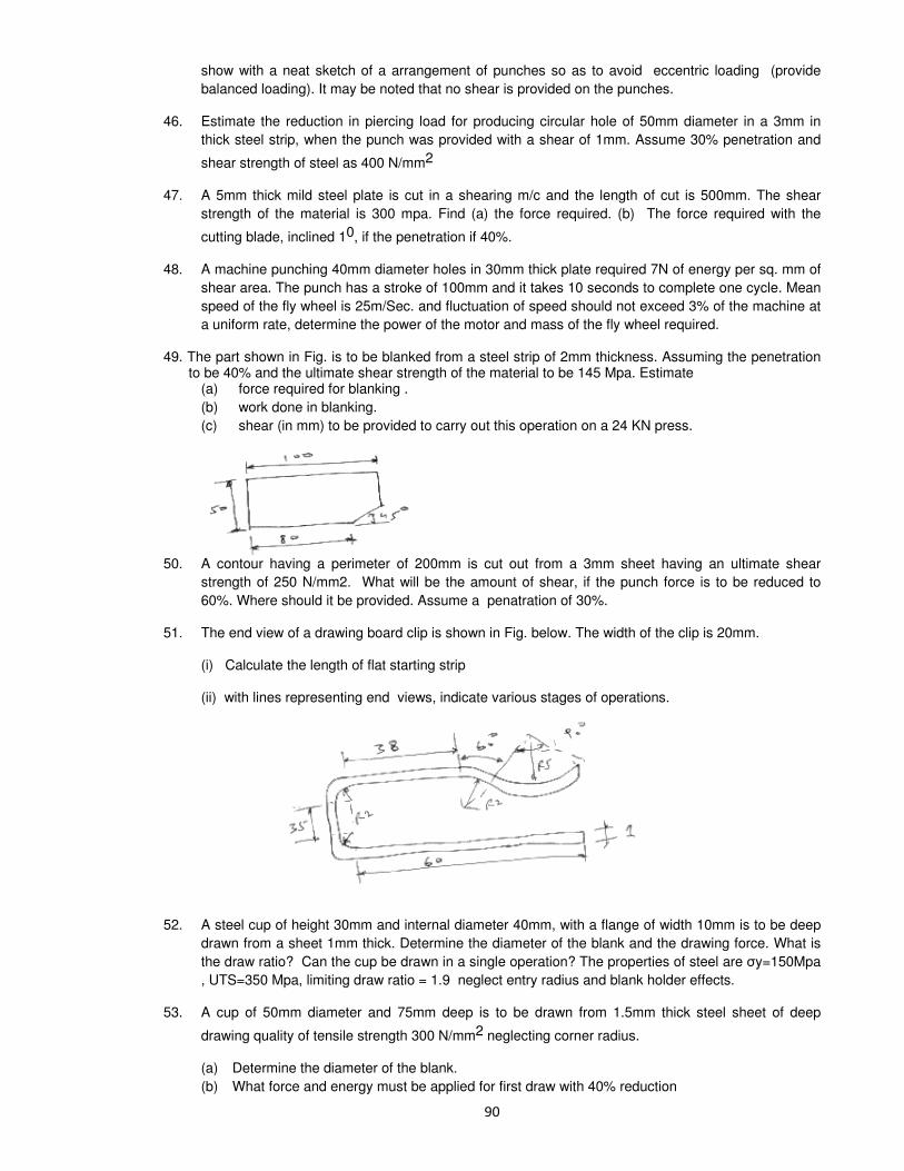
show with a neat sketch of a arrangement of punches so as to avoid eccentric loading (provide
balanced loading). It may be noted that no shear is provided on the punches.
46. Estimate the reduction in piercing load for producing circular hole of 50mm diameter in a 3mm in
thick steel strip, when the punch was provided with a shear of 1mm. Assume 30% penetration and
shear strength of steel as 400 N/mm2
47. A 5mm thick mild steel plate is cut in a shearing m/c and the length of cut is 500mm. The shear
strength of the material is 300 mpa. Find (a) the force required. (b) The force required with the
cutting blade, inclined 10, if the penetration if 40%.
48. A machine punching 40mm diameter holes in 30mm thick plate required 7N of energy per sq. mm of
shear area. The punch has a stroke of 100mm and it takes 10 seconds to complete one cycle. Mean
speed of the fly wheel is 25m/Sec. and fluctuation of speed should not exceed 3% of the machine at
a uniform rate, determine the power of the motor and mass of the fly wheel required.
49. The part shown in Fig. is to be blanked from a steel strip of 2mm thickness. Assuming the penetration to be 40% and the ultimate shear strength of the material to be 145 Mpa. Estimate
(a) force required for blanking .
(b) work done in blanking.
(c) shear (in mm) to be provided to carry out this operation on a 24 KN press.
50. A contour having a perimeter of 200mm is cut out from a 3mm sheet having an ultimate shear
strength of 250 N/mm2. What will be the amount of shear, if the punch force is to be reduced to
60%. Where should it be provided. Assume a penatration of 30%.
51. The end view of a drawing board clip is shown in Fig. below. The width of the clip is 20mm.
(i) Calculate the length of flat starting strip
(ii) with lines representing end views, indicate various stages of operations.
52. A steel cup of height 30mm and internal diameter 40mm, with a flange of width 10mm is to be deep
drawn from a sheet 1mm thick. Determine the diameter of the blank and the drawing force. What is
the draw ratio? Can the cup be drawn in a single operation? The properties of steel are y=150Mpa
, UTS=350 Mpa, limiting draw ratio = 1.9 neglect entry radius and blank holder effects.
53. A cup of 50mm diameter and 75mm deep is to be drawn from 1.5mm thick steel sheet of deep
drawing quality of tensile strength 300 N/mm2 neglecting corner radius.
(a) Determine the diameter of the blank.
(b) What force and energy must be applied for first draw with 40% reduction

54. A cylindrical cup of diameter 12mm and height 16mm has a corner radius of 0.5mm. It is made out of
sheet of 2mm thick and the material has a constant flow stress of 35 mpa. (a) Neglecting the corner radius, estimate the diameter of the blank. (b) Estimate the drawing stress based on ideal deformation (neglecting friction, blank holder force
and of the punch, die corner radius) and check whether it can be drawn in one pass.
55. Determine the maximum possible reduction for a cold rolling, a 300 mm thick slab when µ =0.08 and the roll diameter is 600 mm. What is the maximum reduction on the same mill for hot rolling when
µ =0.5? 56. Calculate the rolling load if steel sheet is hot rolled,30% from a 40 mm thick slab using a 900 mm diameter roll. The slab is 760 mm wide. Assume m= 0.3. The plain stain flow stress is 140
Mpa at entrance and 200 Mpa at the exit from the roll gap due to the increasing velocity.
57. Calculate bite angle when rolling plates 15 mm thick using 400 mm diameter work rolls and reducing the thickness to 3 mm.
58. A metal strip is to be rolled from an initial wrought thickness of 3.5 mm to 2.5 mm in a single pass rolling mill having rolls of 250 mm diameter. The strip is 450 mm wide. The average coefficient of friction in the roll gap is 0.08.Taking plane strain flow stress of 140 Mpa, for the metal and assuming negligible spreading, estimate the roll separating force.
59. When a rectangular section, 100 mm wide and 60 mm thick is rolled to some thickness in one pass with rolls of 400 mm diameter in hot rolling, where the coefficient of friction is 0.3.
1) What is the highest possible reduction in that pass?
2) What will be the length of contact with rolls?
3) If the mean rolling pressure is 500Mpa, what is total rolling load?
60. A circular disc of lead of radius 150 mm and thickness 50 mm is reduced to a thickness of 25 mm by open die forging. If the coefficient of friction between the job and the die is 0.25,
determine the maximum forging force. The average shear yield stress of lead can be taken as 4N/mm2
61. Calculate the maximum number of impressions that can be placed in an injection mold given the following data.
Oil pressure in the hydraulic cylinder = 14 Mpa
Diameter of piston in the hydraulic cylinder = 100 mm
Diameter of injection ram = 100 mm
Projected area of one impression = 2500 mm2
Projected runner area per impression = 625 mm2
Maximum molding capacity = 2.4MN
Mold clamping force should be at least 15% more than the mold operating force. Pressure loss during the
viscous drag between injection chamber and the mold impression is 20%.
62. Clearances have to be provided on the press tools, what is the order of clearances for shearing
operation and deep drawing operation? On what tool will you provide the clearance in
(i) Punching operation (ii) Blanking operation
63. How much force will be required to pierce a circular hole of diameter 20 mm in a 2 mm thick mild steel
plate with the help of flat ended die and punch in a press tool ? The shear strength of the work material is
350 MPa.
64. How fine through holes of diameter less than 50 microns can be made in 1.0 mm thick aluminium
sheets?
65. How is “Bend Allowance” (BA) calculated in sheet metal working?
66. What are the steps involved in making of carbide tool bits? What do you understand by the green
density of a metal powder compacted part? What are the chief merits of a bush made by metal powder
compaction?
67. Enumerate the steps involved in ‘Powder Metallurgy’ process. Discuss these steps. Name the
materials used in ‘Powder Metallurgy’. What are the limitations of Powder Metallurgy?

68. How are powders produced in powder metallurgy process? Name and explain the various steps in
making parts from metal powder.
69. Metal powders are compacted by many methods, but sintering is required to achieve which property ? What is hot isostatic pressing?
70. Group the following into thermosets and thermoplastics:
Acrylic, Alkyds, Polyimide, Nylon, Epoxy, Phenolic, Silicone and PVC.
71. Mention the relative advantageous characteristics of polymer products and their manufacturing over
those of similar metal products.
72. Mention the names of 4 plastics which are used for bearings. Also mention four advantages which plastics offer over other materials.

Machine Tools & Metal cutting
1. The effect of rake angle on the mean friction angle in machining can be explained by a) Sliding (coulomb) model of friction b) Sticking and then sliding model of friction c) Sticking friction d) Sliding and then sticking model of friction.
2. In USM the material removed rate would be . . . . . with increasing mean diameter of the abrasive material.
a) Increase b) Decrease c) Increase and then decrease d) Decrease and then increase 3. The two main criteria for selecting the electrolyte in ECM is that the electrolyte should
a) Be Chemically stable b) Not allow dissolution of cathode material c) Not allow dissolution of anode material d) Have high electrical conductivity
a) A & D b) A&D c) C&D d) D&A
4. In horizontal milling process . . . . (up/down) milling provides better surface finish and .. . . . (up/down)
milling provides longer tool life.
5. Match
A) Square hole in a high strength alloy 1. Drilling B) Square hole in a ceramic component 2. ECM C) Blind holes in a die 3. Jig boring D) Turbine blade on high strength alloy 4. EDM 5. USM a. 5 4 3 2 b.4 5 2 3 c. 4 5 3 2 d. 3 2 4 5 6. A milling cutter having 8 teeth is rotating at 150 rpm. If the feed per tooth is 0.1, the table speed in
mm per minute is a) 120 b) 187 c) 125 d) 70
7. In USM process, the MRR will be higher for materials with
a) Higher toughness b) higher ductility c) Lower toughness d) Higher fracture stain 8. To get good surface finish on a turned job, one should use a sharp tool with a . . . . feed and . . . .
speed of rotation of job.
a) Min., Max. b) Max, Min c) Max, Max d) Min, Min 9. EDM imposes larger forces on Tool than ECM (T/F) 10. EDM is more efficient process than ECM for producing large non-circular holes. (T/F)
11. USM is the best process for making holes is glass which is comparable in size with the thickness of the sheet (T/F)
12. Among the conventional machining processes, maximum specific energy consumed in
a) Turing b) Drilling c) Planning d) Grinding
13. Cutting power consumption in turning can be significantly reduced by
a) Increasing the rake angle b) Increasing the cutting angles of tool

c) Widening the nose radius of the tool d) Increasing the clearance angle 14. Plain milling of MS plate produces
a) Irregular shaped discontinuous chips b) Regular shaped discontinuous chips c) Continuous chips with out built up edge d) Jointed chips 15. Machine tool structures are made . . . . . for high process capability (tough/strong/rigid). 16. Both live center and the dead center of lathes are hardened and lubricated for reducing friction and
wear. (T/F)
17. Diamond wheels should not be used for grinding steel components. (T/F)
18. Match
A) Finish turning 1. Back lash eliminator B) Forming 2. Zero rake C) Thread cutting 3. Nose radius D) Down milling 4. Low speed a) 3 2 4 1 b) 2 3 4 1 c) 3 2 4 1 d) 1 2 3 4 19. Fig. Shows a quick return mechanism. The crank OA rotates clock wise uniformly. 0A=2 cm 00
1=4
cm. The ratio of time for forward motion to that for return motion is
a) 0.5 b) 2.0 c) 2 d) 1
20. The rake angle in a drill
a) Increases from center to periphery b) decreases from center to periphery c) Remains constant d) Is irrelevant to the drilling operation 21. Tool life 10 hours is obtained when cutting with single point tool at 63m/min. If Taylor’s const. C =
257.35, tool life on doubling, the velocity will be a) 5 hrs b) 25.7 min. c) 38.3 min. d) Unchanged
22. Helix angle of fast helix drill is normally
a) 35o b) 60
o c) 90
o d) 5
o
23. Selection of electrolyte for ECM is as follows:
a) Non-passivating electrolyte for stock removed and passivating electrolyte for finish control. b) Passivating electrolyte for stock removed and non-passivating electrolyte for finish control. c) Selection of electrolyte is dependent on current density d) Electrolyte selection is based on Tool-work electrodes
24. Inter electrode gap in ECM is controlled by a) Controlling the pressure of electrolyte flow b)Controlling the applied static load c) Controlling the size of diamond particle in the wheel d) Controlling the texture of the W/P.
25. In a typical metal cutting operation, using a cutting tool of +ve
rake ∝ = 10o, it was observed that the
shear angle was 20o. The friction angle is . . . . .
a) 45o b) 30
o c)60
o d) 40
o
26. A cutting tool has a radius of1.8 mm. The feed rate for a theoretical surface roughness of Ra=5 µm, is
a) 0.36 mm / rev. b) 0.187 mm/rev. c) 0.036 mm/rev. d) 0.0187 mm/rev.

27. Match A) Grinding 1. Surface for oil rotation B) Honing 2. Surface for max. load capacity C) super finishing 3. Surface for limiting friction D) Burnishing 4. Surface of matte finish 5. Surface for pressure sealing 6. Surface for interference fit a) 3 1 2 5 b)1 2 3 5 c) 1 3 2 5 d) 3 1 2 5 28. In an orthogonal machining operation, the chip thickness and the un cut thickness are equal to 0.45
mm. If the tool rake angle is 0o, the shear plane angle is
a) 45o b) 30
o c) 18
o d) 60
o
29. Match
A) ECM 1. Plastic shear B) EDM 2. Erosion / brittle fracture C) USM 3. Corrosive reaction D) Ch.M 4. Melting and vaporization 5.Ion displacement 6. Plastic shear & Ion displacement a) 3 6 2 4 b) 3 1 2 4 c) 5 4 2 3 d) 1 4 2 6 30. In EDM, the tool is made of: a) Copper b) HSS c) CI d) Plain carbon steel
31. What is approximate % change in the life, t, of a tool with zero rake angle used in orthogonal cutting
when its clearance angle, ∝ is changes from 10o to 7
o (Hint: flank wear rate is proportional to cot ∝)
a) 30% increase b) 30% decrease c) 70% increase d) 70% decrease
32. Abrasive material used in grinding wheel selected for grinding ferrous alloy is
a) Silicon carbide b) Diamond c) Aluminum oxide d) Boron carbide
33. Deep hole drilling of small diameter, say 0.2 mm is done with EDM by selecting the tool material as a) Copper wire b) Tungsten wire c) Brass wire d) WC
34. In ECM, the material removal is due to a) Corrosion b) Erosion c) Fusion d) Ion displacement
35. During orthogonal cutting of MS with a 10o rake angle tool, the chip thickness ratio was obtained as
0.4. The shear angles (in degrees) evaluated from this data is
a) 6.53 b) 20.22 c)22.94 d) 50.00
36. A lead screw with half nuts in a lathe, free to rotate in both directions has
a) V-threads b) Whit worth threads c) Buttress threads d) Acme threads
37. Trepanning is performed for
a) Finishing a drilled hole b) Producing a large hole with out drilling
c) Turning a hole for alignment d) Enlarging a drilled hole
38. The hardness of a grinding wheel is determined by the a) Hardness of abrasive grains b) Ability of the bond to retain abrasives c) Hardness of the bond d) Ability of the grinding wheel to penetrate the work piece
39. A built – up – edge is formed while machining a) Ductile material at high speeds

b) Ductile materials at low speeds c) Brittle materials at high speed d) Brittle materials at low speed
40. The time taken to drill a hole through a 25 mm thick plate with the drill rotating at 3.00 rpm and moving at a feed rate of o.25 mm / rev is
a) 10 sec b) 20 sec c) 60 sec d) 100 sec
41. Quality screw threads are produced by a) Thread milling b) Thread chasing c) Thread cutting with single point tool d) Thread casting 42. As tool and work are not in contact in EDM process
a) No relative motion occurs between them b) No wear of tool occurs c) No power is consumed during metal cutting d) No force between tool and work occurs
43. A batch of 10 cutting tools could produce 500 components while working at 50 rpm with a tool feed of 0.25 mm/rev and depth of cut of 1 mm. A similar batch of 10 tools of the same specification could produce 122 components while working at 80 rpm with a feed of 0.25 mm/rev and 1 mm depth of cut. How many components can be produced with one cutting tool at 60 rpm.
a) 29 b) 31 c) 37 d) 42
44. A cylinder is turned on a lathe with orthogonal machining principle. Spindle rotates at 200 rpm. The axial feed is 0.25 mm per revolution. Depth of cut is 0.4 mm. The rake angle is 10
o. In the analysis it
is found that the sheer angle is 27.75o.
i) The thickness of the produced chip is
a) o.511 mm b) 0.528 mm c) 0.818 mm d) 0.846 mm
ii) In the above problem, the coefficient of friction at the chip tool interface obtained using Earnest and Merchant theory is
a) 0.18 b) 0.36 c) 0.71 d) 0.98
45. In whit worth quick return mechanism (used in shapers) the velocity of the ram is maximum at.
a) Middle of the forward stroke b) Beginning of return stroke c) End of return stroke d) None of these 46. By USM, one can efficiently machine: a) Low-carbon steel b) Brass c) Plastics d) Glass
For turning Ni-cr alloy steel at cutting speeds of 64 m/min. and 100 m/min. the respective tool lives are 15 min and 12 min. The tool life for a cutting speed of 144 m/min is
a) 8 min b) 9 min c) 10 min d) 11.5 min.
48. Spline – holes are machined by
a) Milling b) Boring c) Drilling d) Broaching
49. A slab of 50 mm width and 200 mm length is rough machined by a symmetrical milling operation. The cutter diameter is 75 mm. The length of travel of the cutter is
a) 275.00 mm b) 237.50 mm c) 219.54 mm d) 209.55 mm
50. Diamond tipped tools are not used for turning Fe-materials because: a) Diamond has poor Th.Conductivity b) Carbon has good solubility in iron c) Diamond has poor toughness d) The tools are expensive
51. In a single point turning operation with a cemented carbide and steel combination having a Taylor exponent of 0.25, if the cutting speed is halved, the toll life will become approximately:
a) Doubled b) 8 times c) halved d) 6 times

51. (A) Cemented carbide (hard metal) tools are not used for shaping because: a) Cutting speeds in shaping are limited b) Linear reciprocating movement of the tool c) Impact loading at tool entry d) Chip sections are large
52. The specific cutting energy in grinding is very high because: a) The cutting edges have irregular geometry b) Of very high cutting speeds c) Chip sections are small d) Of large centrifugal forces
53. Which of the following machining processes can be used to drill a fine hole in the fuel injector nozzle for diesel engines?
a) Abrasive jet b) Laser beam c) Electro chemical d) Ultrasonic
54. LP cutting fluids are used for broaching operations because
a) They have excellent cooling properties b) Of lower cost/lighter c) They prevent built up edge formation d) Broaches are expensive and can be ground only a limited no. of times.
55. Which of the following machining processes demand electrical conductivity of work material: a) EDM b) EBM c) LBM d) USM
56. Among the following non-traditional machining processes the largest material removal rate associated with:
a) ECM b) USM c) EDM d) LBM
57. Mandrel is used for turning:
a) Long cylindrical parts b) Gear blanks c) Crank shaft d) Outer race of a ball bearing 58. When a medium size batch of short bushings is to be produced, it should be machined on a : a) Center lathe b) Multi tool semi-automatic c) Turret lathe d) Single spindle automatic lathe 59. Match A) Inductosyn 1. Automated work handling B) Group technology 2. Lapping C) Magnetostriction 3. Force measurement D) Pressure intensifier 4. CAD E) Brine 5. CO2 – casting F) Profile cutting 6. EDM G) Inter active graphics 7. USM H) FMS 8. WJM 9. Position feed back 10. Honing 11. Plastic deformation 12. ECM 13. Geometric similarity
a)13,10,3,9,12,7,1,4. b)2, 4, 6, 8 ,10,12,13,5 c)1,3,5,7,9,11,13,8 d) 10,13,9,3,12,7,4,1
60. Increase in rake angles causes ________ in chip thickness and _______ in shear angle.
a. Increase/decrease b. decrease /increase c. Increase /increase d. decrease/ decrease
61. Thrust force in drilling can be reduced by ______ the point angle and by _______ the helix angle of the drill.
a)increase/decrease b)decrease/ increase c)decrease/ decrease d)increase/increase

62. The heat generated in metal cutting is dissipated in different proportions in to the environment, tool, chip and work piece. The correct order of this proportion in decreasing magnitude is (no cutting fluid is used)
a) Tool, W/P, chip environment b) W/P, Tool, Chip environment c) Tool, Chip environment, W/P d) Chip, Tool, W/P environment 63. Only negative rake angles are used with the following tool materials: a) HSS b) Carbon tool steels c) Carbides d) Diamond
64. In metal cutting BUE formation results in: a) Improvement in surface finish b) Reduction in cutting force c) Deterioration of surface finish d) Improvement in tool life
65. A grinding wheel is said to be glazed if:
a) Grains have become blunt, but do not fell out b) Gap between the grains is filled with swarf c) It becomes black due to burning d) Part of the wheel is chipped off
66. When the depth of cut is increased, the specific cutting energy
a) Increases b) Decreases c) Remaining uncharged d) Reaches an optimum value
67. A 60o symmetrical V-tool is used in shaping a work piece with a depth of cut of 0.1 mm and a feed of
0.1 mm/stroke. The theoretical peak-to-valley height, in mm, of the surface produced is . . . . .
a. b. c. d.
68. Reamers have usually even number of teeth so that the cutting forces on teeth are properly balanced (T/F)
69. Match
A) AJM 1. Horn B) EDM 2. Wire as cutting tool C) LBM 3. Light D) USM 4. Vacume 5. Nozzle 6. Cladding
a) 5 2 3 6 b) 2 5 3 6 c) 5 2 6 3 d) 2 3 5 6 70. The life of a cutting tool is long when a) Rake angle is very high and clearance angle low b) Both rake and clearance angles have medium values c) Rake angle is low and clearance angle is high d) Both rake angle and clearance angel are low 71. In down milling, as compared to up milling a) Surface finish is inferior b) Tool life is lower
c) There is a tendency of the job being dragged in to the cutter d) None of the above 72. Power consumption pattern for grinding wheels is a) High in the beginning and comes down gradually b) low in the beginning and increases gradually reaching a constant value. c) Low for too hard wheels d) It remains const. Irrespective of whether the wheel is new or old. 73. In USM process the MRR
a) Is directly proportional to the frequency of waves b) Is inversely proportional to the frequency
c) Does not depend on frequency but increases directly with increasing amplitude of the waves d) Decreases with the increase in the amplitude of the waves.

74. In ECM process a) There is practically no tool wear b) The tool wear varies depending on the nature of material being machined c) The tool wear varies depending on the machining parameters d) No tool is used and there fore there is no tool wear. 75. Major advantage of EDM is that a) It has low Sp. Energy consumption as compared to conventional process. b) It is applicable to non conducting materials c) It can be used for blind complex cavities d) It always given smooth surface finish at larger removed rates. 76. Ceramic tools are useful for _______ speeds but only for __________ cuts.
a) high/light b) high /high c) low /low d) light /light
77. In grinding operations, if grain size of the grit is larger the MRR will be _______ and surface finish will be ______ as compared to finer grits.
a) More/Low b) low /more c) low /low d) more /more
78. As a result of EDM the fatigue strength of the machine parts _______ compared to parts produced by conventional milling.
79. In Honing the material removal is accomplished at lower cutting speeds than grinding. (T/F)
80. Water jet machining used high pressure and high velocity water stream which acts like a saw and cuts a narrow grove in the material. (T/F)
81. The force required for cutting is generated from sudden change in the momentum of the water stream. (T/F)
82. The mechanism of material removed in EDM process is a) Melting and Evaporation b) Melting and corrosion c) Erosion and covitation d) Cavitation and Evaporation
83. Typical machining operations are to be performed on hard-to-machine materials by using the processes listed below. Choose the best set of operations-process combinations.
Operation Process
P. Deburring (Internal surface) 1. PAM Q. Die sinking 2. AJM R. Fine hole drilling in thin sheets 3. EDM S. Tool sharpening 4. USM 5. LBM 6. ECG A) P1 Q5 R3 S4 B) P1 Q4 R1 S2 C) P5 Q1 R2 S6 D) P2 Q3 R5 S6 84. Quality screw threads are produced by
A) Thread milling B) Thread chasing C) Thread cutting with single point tool D) Thread casting
85. As tool and work are not in contact in EDM process A) No relative motion occurs between them. B) No wear of tool occurs C) No power is consumed during metal cutting D) no force between work and tool occurs 86. Formation of built-up edge during machining can be avoided by using A) Tool with low positive rake angle B) High feed rate C) High cutting speed D) Large depth of cut

87. A good cutting fluid should have a) Low thermal conductivity b) High specific heat c) High viscosity d) High density 88. Process Mechanism of material removed P. EDM 1. Erosion Q. ECM 2. Thermal evaporation R. AJM 3. Anodic dissolution 4. Etching A) P2 Q3 R1 B) P2 Q4 R1 C) P1 Q3 R4 D) P4 Q3 R1 89. Group-I Group-II P. Dressing 1. Blunting of grinding wheels Q. Loading 2. Shaping of grinding wheels R. Glazing 3. Sharpening of grinding wheels S. Truing 4. Clogging of grinding wheels A) P2 Q1 R4 S3 B) P3 Q1 R4 S2 C) P3 Q4 R1 S2 D) P4 Q3 R1 S2 90. An orthogonal cutting operation is being carried out under the following conditions: Cutting speed = 2 m/s, depth of cut = 0.5 mm Chip thickness = 0.6 mm. Then the chip velocity is a) 2.0 m/s b) 2.4 m/s c) 1.0 m/s d) 1.66 m/s 91. The angle of inclination of the rake face with respect to the tool base measured in a plane
perpendicular to the base and parallel to the width of the tool is called. a) Back rake angle b) side rake angle
c) side cutting edge angle d) End cutting edge angle 92. In orthogonal cutting test, the cutting force = 900N, the thrust force = 600N and chip shear angle is
30o. Then the chip shear force is
a) 1079.4 N b) 969.4 N c) 479.4 N d) 69.6 N 93. The time taken to face a work piece 72 mm diameter, if the spindle speed is 80 rpm, and cross feed is
0.3 mm/rev is a) 1.5 minutes b) 3.0 minutes c) 5.4 min. d) 8.5 min. 94. The purpose of helical grooves in a twist drill is to 1. Improve the stiffness 2. Save tool material 3. Provide space for chip removal 4. Provide rake angle for the cutting edge Select the correct answer using the codes given below: a) 1 & 2 b) 2 & 3 c) 3 & 4 d) 1 & 4 95. In milling machine, the cutting tool is held in position by a) Chuck b) Spindle c) Arbor d) Tool holder 96. A spur gear of 40 teeth is machined in a gear hobbing machine using a double start hob cutter. The
speed ratio between the job and the blank is a) 1:20 b) 1:40 c) 40:1 d) 20:1
97. Matching
List-I List-II A) Machining of conducting materials 1. ECM

B) Ruby rod 2. EDM C) Electrolyte 3. USM D) Abrasive slurry 4. LBM a) 4213 b) 4231 c) 2431 d) 2413 98. Which of the following mechanisms is employed for indexing of turret in an automatic lathe?
a) Whit worth b) Rake & Pinion c) Ratchet & Pawl e) Geneva wheel 99. A) Vitrified bond is preferred for thin grinding wheels. True/False R) Vitrified bond is hard and brittle True/False
100. A) In EDW M cutting machine shaped tool is replaced by copper wire True/False R) The discharge takes place between wire and work price True/False
101. What do you understand from machinability of a material. List any two properties, which have a bearing on machinability
102. Distinguish between electro chemical machining and electro chemical grinding 103. Explain the difference between orthogonal and oblique cutting. In an orthogonal cutting process, the
following observations were made: Depth of cut = 0.25 mm; Chip thickness ratio = 0.45; Width of cut = 4mm Cutting velocity = 40m/m; Cutting force component || to cutting velocity vector = 115oN
Cutting force component ⊥r to cutting velocity vector = 640N Rake angle of the tool = 18
0 Determine resultant cutting force, power of cutting, shear plane angle,
friction angle and force component parallel to shear plane. 104. List the various gear cutting processes. How are they classified? Describe with simple sketches the
principle and working of a gear shaper. 105. In center less grinding the work piece center will be a. above the line joining the two wheel centers b. below the line joining the two wheel centers c. on the line joining the two wheel centers d. at the intersection of the line joining the wheel centers with the work piece plane 106. A) For a negative rake tool, the specific cutting pressure is smaller than that for a positive rake tool under other wise identical conditions True/False
R) The shear strain under zone by the chip in case of negative rake tool is larger T/F
107. A) Soluble oils are employed with broaching machine True/False R) Soluble oils have excellent cooling effect True/False
108. A) No relative feed motion is required during broaching True/False R) The relative heights of successive teeth in broach gradually increase T/F
109. Show with a neat sketch the forces acting on a chip in orthogonal machining. Derive an expression to calculate the coefficient of friction between the tool-chip interface
110. A seam less tube 32mm outside diameter is turned on a lathe cutting velocity of the tool relative to the work piece is 10 m/min. Rake angle = 35
0 depth of cut =0.125 mm length of chip = 60mm,
Horizontal cutting force of the tool on the w/p = 200N, cutting force to hold tool against work = 80N.
Calculate µ, r, v, va, vs. 111. A) Tool wear is expressed in terms of flank wear rotten the crater wear True/False R) Measurement of flank wear is simple and more accurate True/False
112. The following parameters determine the model of continuous chip formation 1) true feed 2) cutting velocity 3) chip thickness 4) rake angle of tool
The parameters which govern the value of shear angle would include
a. 1,3 & 4 b. 2, 3 & 4 c. 1, 2 & 3 d. 1, 2 & 4
113. What is the correct sequence of the following parameters in order of their maximum to minimum influence on tool life?
1. feed rate 2. depth of cut 3. cutting speed
a. 1, 2, 4 b. 3, 1, 2 c. 1, 3, 4 d. 4, 3, 1

114. Tool geometry of a single point cutting tool is specified by the following elements? 1. back rake angle 2. side rake angle 3. end cutting edge angle 4. side cutting edge angle 5. side relief angle 6. end relief angle 7. nose radius a. 1,2,6,5,3,4,7 b. 2,1,4,3,5,7,6 c. 4,2,1,3,5,7,6 d. 3,4,1,2,6,5,7 115. The ratio of thrust force to cutting force is nearly 2.5 in a. turning b. broaching c. grinding d. plain milling
116. Which one of the following operations is carried out at the minimum cutting velocity if the machines are equally rigid and the tool work materials are the same?
a. turning b. grinding c. boring d. milling
117. Given that average cutting speed = 9 m/min. Return time to cutting time ratio = 1 : 2 Feed rate = 0.3 mm/stroke Clearance at each end of cut = 25mm and that the plate is fixed with 700mm side along the direction of tool travel, the time required for
finishing one flat surface of a plate of size 700 × 30mm in a shaper, will be a. 10min b. 12.5 min c. 15 min d. 20 min 118. Consider the following statements regarding grinding of high
1. Grinding at high speed results in the reduction of chip thickness and cutting forces per grit 2. Al2O3 wheels are employed 3. the grinding wheel has to be of open structure Of these statements which are correct a. 1, 2 & 3 b. 1 & 2 c. 1 & 3 d. 2 & 3 119. Enlarging an existing hole (circular) with a rotating single point tool is called a. boring b. drilling c. reaming d. internal turning
120. Consider the following operations 1. cutting key ways on shafts 2. cutting external screw threads 3. cutting teeth of spur gears 4. cutting external splines Those which can be performed with milling cutters would include a. 1,2,3 & 4 b. 1,2 & 3 c. 2,3 & 4 d. 1, 2 & 4 121. Consider the following machine tools 1. hobbing machine 2. gear shaping machine 3. broaching m/c The teeth of internal spur gears can be cut in a. 2 & 3 b. 1 & 3 c. 1 & 2 d. 1, 2 & 3 122. In reaming process a. metal removal rate is high b. high surface finish is obtained c. high form accuracy is obtained d. high dimensional accuracy 123. The ratio between the consecutive spindle speeds for a six-speed drilling machine using drills of
diameter 6.25 to 25mm size and at a cutting velocity of 18mm/ sec
a. 1.02 b. 1.32 c. 1.06 d. 1.82 124. In a single spindle automatic lathe, two tools are mounted on the turret, one form tool on the front
slide and the other, a parting tool on the rear slide. The parting tool operation is much longer than form tool operation and they operate simultaneously (over lap) the no. of gears required for this job is a. 1 b. 2 c. 3 d. 4
125. Give two functions of a coolant 126. Distinguish between flank wear and crater wear of a single point cutting tool 127. Expand EDM

128. Distinguish between orthogonal and oblique cutting. Derive an expression for the shear plane angle in turning operations on a lathe. Explain all the assumptions made to arrive at the solution
129. The angle between the face and the flank of the single point cutting tool is known as a. rake angle b. clearance angle c. lip angle d. point angle
130. Single point thread cutting tool should have a. zero rake b. positive rake c. negative rake d. normal rake
131. Consider the following statements about nose radius 1. it improves tool life 2. it reduces the cutting force 3. it improves the surface finish Of these statements which are correct a. 1 & 3 b. 1 & 2 c. 2 & 3 d. all 132. Crater wear is predominant in a. carbon steel tools b. Tungston carbide tools c. HSS tools d. ceramic tools
133. The primary tool force used in calculating the total power consumption in machine is the a. radial force b. tangential force c. axial force d. frictional force
134. In the grinding wheel of A, 60, Be, B stands for a. rasenoid bond b. rubber bond c. shellac bond d. silicate bond
135. Soft materials can not be economically ground due to a. high temp. involved b. frequent wheel clogging c. rapid wheel wear d. low work piece stiffness 136. In a milling operation two side milling cutters are mounted with desired distance between them, so
that both sides of a w/p can be machined simultaneously. This set up is called a. gang milling b. straddle milling c. string milling d. scale milling
137. The effects of setting a boring tool above ‘center height’ leads to a) increase in the effective rake angle and decrease in the effective clearance angle b) increase in both effective rake angle and effective clearance angle c) decrease in the effective rake angle and increase in effective clearance angle d) decrease in both effective rake angle and effective clearance angle
138. In a mechanical shaper, the length of stroke is increased by a. increasing the center distance of bull gear and crank P in b. decreasing the center distance of bull gear and crank P in c. Increasing the length of ram d. decreasing the length of the slot in the slotted lever 139. While cutting helical gears on a non-differential gear hobber, the feed change gear ratio 140. R) Up milling can be done on universal milling machine True/False A) Up milling or climb milling is commonly used for machining casting & forging T/F
141. A) In a suits – type automatic lathe, the turret is given longitudinal feed for each tool in a specific order with suitable indexing True/False R) A turret is a multiple tool holder to facilitate machining with each tool by indexing with out need to change the tool True/False 142. A) A chip breaker is employed to improve machinability of brass True/False R) A chip breaker facilitates the curling and breakage of long continuous chip T/F
143. In which machine tool the whit worth quick return mechanism is used? 144. Expand the abbreviation ECM 145. Chip equivalent is increased by a. an increase in side-cutting edge angle of tool b. an increase in nose radius and side cutting edge angle of tool c. increasing the plan area of cut d. increasing depth of cut 146. A machinst desires to turn a round steel stock of out side diameter 1000mm at 100 rpm. The
material has tensile strength of 75 kg/mm2. The depth of cut chosen is 3mm at a feed rate of
0.3mm/rev. which one of the following tool material will be suitable for machining the component under the specified cutting conditions?
a. sintered carbides b. ceramics c. HSS d. diamond

147. Notch wear at the outside edge of the depth of cut is due to a. abrasive action of the work hardened chip material b. oxidation c. slip-stick action of chip d. chipping 148. Which of the following indicate better machinabilities 1. smaller shear angle 2. higher cutting forces 3. longer tool life 4. better surface finish a. 1 & 4 b. 2 & 4 c. 1 & 2 d. 2 & 4 149. In turning of slender rods, it is necessary to keep the transverse force minimum mainly a. improve the surface finish b. increase productivity c. improve cutting efficiency d. reduce vibrations & chatter 150. Which of the following forces are measured directly by 1. force exerted by the tool on the chip acting normally to the tool face 2. horizontal cutting force exerted by the tool on the work price 3. frictional resistance of the tool against the chip flow acting along the tool face 4. vertical force which helps in holding the tool in position a. 2 & 4 are correct b. 1 & 2 are correct c. 2 & 3 are correct d. 1 & 4 are correct 151. A grinding wheel of 150mm diameter is rotating at 3000 rpm. The grinding speed is
a. 7.5 π m/sec b. 15 π m/sec c. 45 π m/sec d. 450 π m/sec
152. Specific energy requirements in a grinding process are more than those in turning for the same MRR because of the
a. specific pressure between wheel and work being high b. size effect of the larger contact areas between wheel and work c. high cutting velocities d. high heat produced during grinding 153. Grinding wheel is said to be loaded when the a. metal particles get embedded in the wheel surface blanking the interspaces between cutting
grains b. bonding material comes on the surface and the wheel becomes blunt
c. work price being ground comes to a stop in cylindrical grinding d. grinding wheel stops because of very large depth of cut
154. Which of the following statements is correct 1. a boring machine is suitable for job shop 2. a jig boring machine is designed specially for doing more accurate work when compared to a
vertical milling machine 3. a vertical precision boring machine is suitable for boring holes in cylinder blocks and liners a. 1 & 3 b. 2 & 3 c. 1, 2 & 3 d. 1 & 2
155. Consider the following processes of gear manufacturing 1. milling with form cutter 2. rack type gear shaper (gear planer) 3. rotary gear shaper (gear shaper) 4. gear hobbing The correct sequence of these processes in increasing order of accuracy of involute profile of the
gear is
a. 3, 2, 4, 1 b. 1, 4, 2, 3 c. 2, 3, 1, 4 d. 3, 2, 1, 4
156. Gear cutting on milling machine using an involute profile cutter is
a. gear forming process b. gear generating process c. shaping process d.highly accurate gear producing process
157. For the manufacture of full depth spur gear by hobbing process, the no. of teeth to be cut = 30,
module = 33mm and pressure angle = 200. The radial depth of cut to be employed should be equal
to a. 3.75mm b. 4.5mm c. 6.00mm d. 6.75mm
158. In turning operation, determine the material removal rate, if depth of cut = 2mm, feed per revolution = 0.5mm and surface velocity of the job = 50m/min.

159. Explain the working principle of ECM. Discuss how the machining rate in this process is affected by the following
i) rate of flow of electrolyte ii) temperature of electrolyte iii) applied voltage between tool and work price 160. In orthogonal cutting, the depth of cut is 0.5mm at a cutting speed of 2m/sec. If the chip thickness is
0.75mm, the chip velocity is a. 1.33 m/sec b. 2 m/sec c. 2.5 m/sec d. 3 m/sec
161. Consider the following elements 1. Nose radius 2. cutting speed 3. depth of cut 4. feed
The correct sequence of these elements in decreasing order of their influence on tool life
a. 2, 4, 3, 1 b. 4, 2, 1, 3 c. 2, 4, 1, 3 d. 1, 3, 2, 4
162. The rake angle in twist drill a. varies from minimum near the dead center to a maximum value at the periphery b. to maximum at the dead center and zero at the periphery
c. is constant at every point of the cutting edge d. is a function of the size of the chisel edge
163. Which of the following processes does not cause tool wear? a. USM b. ECM c. EDM d. anode mechanical machining
164. Consider the following forces acting on a finish turning tool 1. feed force 2. trust force 3. cutting force
The correct sequence of the decreasing order of the magnitudes of these forces is
a. 2, 3, 1 b. 3, 2, 1 c. 3, 1, 2 d. 1, 2, 3
165. Match
Type of drill Application
A. Straight shank 1. soft material B. taper shank 2. deep holes C. single flute 3. general purpose D. high helix 4. small hole diameter a. A-3,B-4,C-2,D-1 b. A-4,B-3,C-1,D-2 c. A-4,B-3,C-2,D-1 d. A-2,B-1,C-3,D-4 166. Which of the following are the advantages of a hydraulic shaper over a mechanically driven shaper 1. more strokes/min can be obtained at a given cutting speed 2. the cutting stroke has a definite stopping point 3. it is simple in construction 4. cutting speed is constant throughout most of the cutting stroke Which of these are correct a. 2 and 4 b. 1 and 4 c. 2 and 3 d. 1 and 3 167. Consider the following operations 1. under cutting 2. plain turning 3. taper turning 4. thread cutting
Correct sequence of these operations in machining a product is
a. 4, 1, 3, 2 b. 1, 4, 3, 2 c. 3, 2, 4, 1 d. 2, 3, 1, 4
168. Consider the following statements in up milling process 1. the cutter starts the cut from the machined surface and proceeds upwards 2. the cutter starts the cut from the top surface and proceeds downwards. 3. the job is fed in a direction opposite to that of cutter rotation 4. the job is fed in the same direction as that of cutter rotation a. 1 & 3 are correct b. 1 & 2 are correct c. 2 & 3 are correct d. 2 & 4 are correct

169. Which of the following motions are NOT needed for spur gear cutting with a hob? 1. rotary motion of job 2. linear axial reciprocatory motion of job 3. rotary motion of gear blank 4. radial advancement of job a. 1, 2, 3 b. 2, 3, 4 c. 1, 3, 4 d. 1, 2, 4 170. Match Gear component Method of Mfg. A. Gear for clocks 1. Hobbing B. Beckalite gear 2. Stamping C. Al – gears 3. Powder compacting D. Automobile transmission gear 4. Sand casting 5. Extrusion a. A-2,B-3,C-5,D-1 b. A-3,B-2,C-5,D-1 c. A-2,B-3,C-1,D-5 d. A-1,B-5,C-3,D-2 171. The type of quick return mechanism employed mostly in shaping machines is a. DC reversible motor b. fast and loose pulleys c. whit worth motion d. slotted link mechanism 172. A) In a slow speed high pressure metal cutting process such as gear cutting, chlorinated or
sulphonated oils are used True/False R) Reduction of coefficient of friction is achieved by the formation of solid film at the rubbing
interface of tool and chip. True/False
173. In a surface grinding operation of work piece of size 20cm (length) × 10cm (width), the speed of table is 25m/min and feed is 0.2 mm/stroke. Determine the time for grinding single surface in a single cut.
174. What is gang milling? 175. A 400mm long shaft has a 100mm tapered step at the middle with 4
0 included angle. The tail stock
offset required to produce this taper on a lathe would be a. 400 sin 4
0 b. 400 sin 2
0 c. 100 sin 4
0 d. 100 sin 2
0
176. A single start thread of pitch 2mm is to be produced on a lathe having a lead screw with a double start thread of pitch 4mm. The ratio of speeds between the spindle and lead screw for this operation is
a. 1 : 2 b. 2 : 1 c. 1 : 4 d. 4 : 1
177. Match A. Reaming 1. Smoothing and squaring surface around the hole for Proper seating B. Counter boring 2. Sizing and finishing the hole C. Counter sinking 3. Enlarging the end of the hole D. Spot facing 4. Making a conical enlargement at the end of the hole a. A-2,B-3,C-4,D-1b. A-1,B-4,C-3,D-2 c. A-4,B-1,C-2,D-3 d. A-2,B-3,C-1,D-4 178. Which one of the following pairs of parameters and effects is NOT correctly matched a. large wheel diameter - Reduced wheel wear b. large depth of cut - increased wheel wear c. large work diameter - increased wheel wear d. large wheel speed - reduced wheel wear 179. In metal cutting operation, the approximate ratio of heat distributed among chip, tool and work, in
that order is a. 80 : 10 : 10 b. 33 : 33 : 33 c. 20 : 60 : 10 d. 10 : 10 : 30
180. A component requires a hole which must be with in the two limits of 25.03 and 25.04mm diameter, which of the following statements about the reamer size are correct?
1. reamer size can’t be below 25.03m 2. reamer size can’t be above 25.04m 3. reamer size can be 25.04mm 4. reamer size can be 25.03mm

a. 1 and 2 b. 2 and 3 c. 2 and 4 d. 1 and 4 181. On a lathe, the actual machining time required per work price is 30 minutes. Two types of carbide
tools are available, both having a tool life of 60 minutes. Type I : Brazed type of original cost Rs.50/- Type II : Throw away tip (square) of original cost Rs.70/- If the overall cost of grinding the cutting edge is Rs.10/-, assuming that all the other costs are the
same for both the types, for break even costs, the appropriate batch size would be a. 2 pieces b. 4 pieces c. 6 pieces d. 8 pieces 182. The variable cost and production rate of a machining process against cutting speed are shown in the
fig. for efficient machining, the range of best cutting speed would be between
a. 1 and 3
b. 1 and 5
c. 2 and 4
d. 3 and 5
183. Matching Machining process Associated medium A. USM 1. Kerosene B. EDM 2. Abrassive slurry C. ECM 3. Vaccum D. EBM 4. Salt solution a. A-1,B-2,C-4,D-3 b. A-2,B-1,C-4,D-3 c. A-2,B-1,C-3,D-4 d. A-1,B-2,C-3,D-4 184. State standard point angle and helix angle of a twist drill 185. What is high efficiency range and high-economic range (Hi-E) in machining? Why is it called so?
186. The results of machining steel with two grades of tool materials are given below
Tool Taylor’s exponent cutting speed for one minute tool life, m/min A 0.20 100 B 0.25 120 i) What are the standard tool life equations for these two material ii) For a 180 minute tool life, which tool is recommended and why?
iii) If the tool grinding and changing time is 15 minutes, which cutting speed for the tool ‘A’ has to be chosen from the two available speeds, 45 m/min, 50m/min?
187. What is the difference between counter-boring and counter sinking? 188. What are the basic differences between gear milling and gear hobbing? 189. What are basic differences between facing at constant speed and facing at constant feed?
190. A surface 80mm × 160mm is rough machined using a face milling cutter of 150mm diameter having 10 teeth. The cutter center is off set by 15mm from the line of symmetry of the surface. Estimate the time to rough machine the surface if the feed per tooth is 0.25mm and a cutting speed of 20m/min. is employed?
i) with 5mm approach and 5mm over-run what is the single pass feed time?
ii) if tool axis is symmetrical with the job, what happens to the machining time?
191. Which of the following sets of forces are encounted by a lathe parting tool while groove cutting? a. tangential, radial and axial b. tangential and axial c. tangential and axial d. radial and axial 192. In a single point turning operation of steel with a cemented carbide tool, Taylor’s tool life exponent is
0.25. If the cutting speed is halved, the tool life will increase by a. 2 times b. 4 times c. 8 times d. 16 times
tiable cosvar
rateproduction

193. Consider the following approaches normally applied for the economic analysis of machining 1. max. production rate 2. max. profit criterion 3. minimum cost criterion
Correct sequence in ascending order of optimum cutting speed obtained by these approaches is
a. 1, 3, 2 b. 2, 3, 1 c. 1, 2, 3 d. 3, 2, 1
194. turning operation, the feed could be doubled to increase the metal removal rate. To keep the same level of surface finish the nose radius of the tool should be
a. halved b. kept unchanged c. doubled d. made 4 times
195. The radial force in single – point tool during turning operation varies between a. 0.2 to 0.4 times the main cutting force b. 0.4 to 0.6 times the main cutting force c. 0.6 to 0.8 times the main cutting force d. 0.5 to 0.6 times the main cutting force 196. Match Drill bits Applications A. Core drill 1. To enlarge a hole to a certain depth B. Reamer 2. To drill and enlarge to an already existing hole in casting C. Counter bore drill 3. To drill a hole before making internal thread D. Tap drill 4. To improve surface finish and dimensional accuracy of The already drilled hole a. A-2,B-4,C-1,D-3 b. A-4,B-2,C-1,B-3 c. A-1,B-3,C-2,D-4 d. A-2,B-4,C-3,D-1 197. Consider the following reasons 1. grinding wheel is soft 2. RPM of grinding wheel is too low 3. cut is very fine 4. An improper cutting fluid is used A grinding wheel may become loaded due to reason stated at a. 1 b. 2 c. 3 d. 4 198. Which one of the following processes results in the best accuracy of the hole made? a. drilling b. reaming c. broaching d. boring
199. The straight teeth slab milling cutter of 100mm diameter and 10 teeth rotating at 200 rpm is used to remove a layer of 3mm thickness from a steel bar. If the table feed is 400mm/min, the feed per tooth in this operation will be
a. 0.2mm b. 0.4mm c. 0.5mm d. 0.6mm
200. Consider the following processes of manufacture of gears 1. Casting 2. Powder metallurgy 3. Machining from bar stock 4. Closed die forging The correct sequence in increasing order of bending strength of gear teeth a. A-1,B-3,C-4,D-2 b. A-3,B-1,C-4,D-2 c. A-4,B-2,C-3,D-1 d. A-3,B-1,C-2,D-4 201. Match A. Die sinking 1. AJM B. De burring 2. LBM C. Fine hole drilling (thin materials) 3. EDM D. Cutting/Sharpening hard materials 4. USM 5. ECM a. A-3,B-2,C-2,D-5 b. A-3,B-1,C-5,D-2 c. A-1,B-3,C-2,D-5 d. A-2,B-3,C-1,D-5 202. Consider the following statements regarding reaming process 1. reaming generally produces a hole larger than its own diameter 2. generally rake angles are not provided on reamers 3. even numbers of teeth are preferred in reamer design Which of these statements is correct? a. 1 & 2 b. 2 & 3 c. 1 & 3 d. all

203. A 60 teeth gear when hobbed on a differential hobber with a two-start hob, the index change gear
ratio is governed by which one of the following Kinematic balance equation? a. 1 revolution of gear blank = 1/60 of hob revolutions b. 1 revolution of gear blank = 2/60 of hob revolutions
c. 1 revolution of hob = 2/60 of blank revolutions d. 1 revolution of hob = 1/60 of blank revolutions
204. A right hand helical gear is being cut on a milling machine. What changes in machine settings have to be made to cut a left hand helical gear of same pitch and number of teeth?
205. What is the direction of movement of the cutter while cutting left hand thread on a lathe? 206. The following equation for tool life was obtained for H.S.S tool VT
0.13 f
0.6 d
0.3 = C
A 60 min. tool life was obtained using the following cutting conditions. V = 40m/min, f = 0.25 mm , d= 2.0mm
Calculate the effect of on tool life if speed, feed and depth of cut are together increased by 25% where f = feed, d = depth of cut, V=speed.
207. Which of the following features improved the fatigue strength of a metallic material? a. increasing the temperature b. stretching the surface c. over stressing d. under stressing 208. Which of the following properties is more sensitive to increase in strain rate a. yield strength b. proportional limit c. elastic limit d. tensile strength 209. Consider the following advantages 1. Rapid process 2. key ways can be ground 3. No work holding device is required
Which of these are the advantages of center less grinding
210. A) Oil as a cutting fluid results in a lower coefficient friction True/False R) Oil forms a thin liquid film between the tool face and chip and it provides ‘hydrodynamic
lubrication’ True/False
211. A) In metal cutting, the normal laws of sliding friction are not applicable True/False R) Very high temperature is produced at the tool-chip interface True/False
212. A) The ratio of cutting force to thrust force is very high in grinding process as compared to other machining processes True/False
R) Random orientation and effective negative rake angles of abrasive grains increase the cutting force and adversely affect the cutting action and promote rubbing action T/F
213. In orthogonal cutting test, the cutting force and thrust force were observed to be 1000N and 500N resp. If the rake angle of tool is zero, the coefficient of friction in chip-tool interface will be
a. 1/2 b. 2 c. 1/√2 d. √2
214. The magnitude of cutting speed for maximum profit rate must be
a. in between the speeds for minimum cost and max. production rate b. below the speed for minimum cost
c. equal to the speed for minimum cost d. d. higher than speed for max. production rate
215. The sequence of markings “S 14K14 S” on a grinding wheel represents resp. a. bond type, structure, grade, grain size and abrasive type b. abrasive type, grain size, grade structure and bond type c. bond type, grade, structure, grain size and abrasive type
e. abrasive type, structure, grade, grain size and bond type
216. In a tool life test, doubling the cutting speed reduces the tool life to 1/8th of the original. The Taylor’s
tool life index is

a. 1/2 b. 1/3 c. 1/4 d. 1/8
217. Consider the following statements In electro chemical grinding
1. a rubber bonded alumina grinding wheel acts as the cathode and the work piece as the anode 2. a copper bonded alumina grinding wheel acts as the cathode and the work piece as the anode 3. metal removal takes place due to the pressure applied by grinding wheel 4. metal removal takes place due to electrolysis
Which of these statements are correct a. 1 b. 3 c. 4 d. 2 218. Which one of the following sets of tools or tools and processes are normally employed for making
large diameter holes? a. boring tool b. BTA tool (boring & trepaning association)and gun drill c. gun drill and boring tool d. boring tool and trepaning 219. Which one of the following processes of gear manufacture results in best accuracy of the involute
gear tooth profile a. milling b. hobing c. rotary gear shaper d. rack type gear shaper
220. One of the index plates of a milling machine dividing head has the following hole circles : 15; 16; 17; 18; 19; 20 A gear wheel of 34 teeth has to be milled by simple indexing method. To machine each tooth, the index crank has to be rotated through
a. 17 holes in the 20 – hole circle b. 18 holes in the 20 - hole circle c. 1 revolution and 3 holes in 17-hole circle d. 1 revolution and 2 holes in 18-hole circle 221. A) Diamond tools can be used at high speeds T/F R) Diamond tools have very low coefficient of friction T/F
222. A) Hard wheels are chosen for grinding hard metals T/F R) In hard wheels only the abrasive grains are retained for long time T/F
223. A) Buttress thread is a modified square thread profile which employed on the lead screw of machine tools T/F R) Frequent engagement and disengagement of lead screw for automatic feed is not possible with perfect square threads, therefore, the square profile has to be modified
224. A) No separate feed motion is required during broaching T/F R) The broaching machines are generally hydraulically operated T/F
225. If α is the rake angle of the cutting tool. φ is the shear angle and V is the cutting velocity, then the velocity of chip sliding along the shear plane is given by
226. Match Cutting Tools Applications A. Trepanning tool 1. For surface finishing by honing B. Side milling cutter 2. For machining gears C. Hob cutter 3. For cutting key ways in shaft D. Abrasive sticks 4. For drilling large diameter holes a. 4 3 1 2 1 b. 3 4 2 1 c. 4 3 2 1 d.1 2 3 4 227. Dry and compressed air is used as cutting fluid for machining? a. steel b. aluminium c. cast Iron d. brass
228. For cutting of brass with single point cutting tool on a lathe, tool should have a. negative rake angle b. positive rake angle c. zero rake angle d. zero side relief angle
229. Power consumption in metal cutting is mainly due to a. tangential component of force b. longitudinal component of force c. normal component of force d. friction at the metal tool interface 230. Crater wear starts at some distance from the tool because a. cutting fluid can’t penetrate that region

b. stress on rake face is maximum at that region c. tool strength is minimum at that region d. tool temp is maximum at that region 231. Matching A. Quick return mechanism 1. Lathe B. Apron mechanism 2. Milling machine C. Indexing mechanism 3. Shaper D. Regulating wheel 4. Center less grinding a. A-3,B-1,C-2,D-4 b. A-1,B-3,C-4,D-2 c.A-1,B-3,C-2,D-4 d. A-4,B-2,C-3,D-1 232. Consider the following characteristics of a robot 1. the tip of robot arm moves from one point to another with its in between path not being defined 2. It can be used for drilling hole at different points in a work pieces 3. it can be used for U-butt joint welding between two points 4. The memory capacity required for its control unit is low Which of these are the characteristics associated with a point to point robot a. 1 b . 2 c. 3 d. 4 233. Consider the following tools 1. H-C steel tools 2. HSS tools 3. Ceramic tools 4. carbide tools Which of these tools are provided with negative rake angle? a. 1 b . 2 c. 3 d. 4 234. Name two criteria for cutting tool life. The following data from the orthogonal cutting test is available:- Rake angle = 10
0 chip thickness ratio = 0.35, un cut chip thickness = 0.51 width of cut = 3mm shear
yield stress of work material = 285 N/mm2. Mean friction coefficient on tool face = 0.65, Determine
the i) cutting force ii) radial force iii) normal force tool and iv) shear force on the tool 235. In a shaper machine, the mechanism for tool feed is a. Geneva mechanism b. whit worth mechanism c. Ratchet and pawl mechanism d. ward-leonard system
236. The marking on a grinding wheel is ‘51A36LV93’ the code ‘36’ represents
a. structure b. grade c. grain size d. manufacture number
237. Specific cutting energy is more in grinding process compared to turning because a. grinding (cutting) speed is higher b. the wheel has multiple cutting edges (grains) c. plonghing force is significant due to small chip size d. grinding wheel undergoes continuous wear
238. The spindle speed range in a general purpose lathe is divided into steps which approximately follow a. arithmetic progression b. geometric progression c. harmonic progression d. logarithmic progression 239. The indexing of the turret in a single spindle automatic lathe is done using a. Geneva mechanism b. Ratchet and pawl mechanism c. Rack and pinion mechanism d. whit worth mechanism 240. Comment on the machined surface characteristics after EDM process 241. Discuss in brief the flank and crater tool wear mechanisms 242. In a certain machining operation with a cutting speed of 50 m/min, tool life of 45 minutes was
observed when the cutting speed was increased to 100 m/min, the tool life decreased to 10 minutes, estimate the cutting speed for maximum productivity, if tool change time is 2 minutes
243. Discuss the technical and economic reasons leading to the development of N on Traditional machining (NTM) processes

a. metals of high temp use with ceramic like properties b. ceramics with metallic strength and lusture c. coated tool materials d. metallic – ceramic composites 244. Gibbs phase rule is given by (F = no. of degrees of freedom) C = no. of compsotions P = no. phases a. F = C + P b. F = L + P – 2 c. F = C – P – 2 d. F = C – P + 2 245. Two cooling curves A and B for a eutectoid iron-carbon alloy are superimposed on a continuous
cooling transformation diagram as shown in the above fig. in pearlite microstructure is represented by the points (s) labeled
a. I and II b. II c. IV d. I 246. Match A. Toughness 1. Moment area method B. Endurance strength 2. Hardness C. Resistance to abrasion 3. energy absorbed in a tension test D. Deflection in a beam 4. Fatigue loading a) 1 2 3 4 b) 3 4 2 1 c) 2 1 3 4 d) 1 2 4 3 247. A) Ceramic tools are used only for light, smooth and continuous cuts at high speeds. R) Ceramics have a high wear resistance and high temp. resistance
248. A) Machine tool beds are generally made of grey cast iron R) cast iron possesses good self-lubricating properties
249. Name four type of steel castings? 250. Match Alloying element in steel Effect A. Lead 1. Restricts grain growth B. Al 2. Raises yield point C. Copper 3. Reduces strength to impact D. Phosphorous 4. Free machining a) 4 1 3 2 b) 1 2 3 4 c) 4 1 2 3 d) 1 4 2 3 251. From the aspect of corrosion explain how a tin plated iron sheet is different from a galvanised iron
sheet. 252. What properties are expected of alloys used in bearings. Describe the role of hard particle and soft
matrix in the functioning of a bearing alloy. 253. Name the strongest and weakest type of atomic bonds 254. Ceramets are 255. The following part program refers to machining of a circular slot on CNC milling machine …….Metric
Units, Absolute co-ordinate system N0050 G01 X50.0 Y75.0 Z-1.0 F100 N0060 G02 X70.0 Y55.0 R20.0 F80 The center of the slot is a) (50,75 ) b) (70,55) c) (50,55) d) (70,75) 256. Tool life equations for two tools under consideration are as follows
HSS : VT0.2
=150 carbide : VT0.3
=250 where V is the cutting speed in m/min and T is to life in min. The break even cutting speed above which the carbide tool will be beneficial is
a) 54 m/min b) 150 m/min c) 194 m/min d) 250 m/min
257. A single point cutting tool with a nose radius of 0.4 mm was used to turn a component in a lathe employing a feed rate of 0.3mm /rev. If the feed rate is doubled, the ideal surface roughness ( peak – to – valley height ) produce on the component will increase by a factor of a) 2 b) 4 c) 8 d) 16
I
II
III IV
A
B

258. Through holes of 10mm diameter are to be drilled in a steel plate 20mm thickness. Drill spindle speed is 300 rpm, feed 0.2 mm /rev. and drill point angle is 120
0 . Assuming drill over travel of 2mm,
the time for producing a hole will be a) 4 Sec. b) 25 Sec. c) 100 Sec. d) 110 Sec.
259. The following data refers to a slab milling operation
Dia.of cutter =50mm No.of teeth on cutter =12 Cutter spindle speed =300 rpm Depth of cut =2mm Length of job =500mm Longitudinal table feed =200 mm/min. (i) The feed per tooth during milling operation is a) 0.056 mm b) 0.167mm c)8.662mm d) 17.333mm
(ii) If the cutter over travel is 2mm, the machining time for single pass milling operation will be a) 0.67min b) 1.5 min c) 1.67min d) 2.76min
260. The following data refers to an orthogonal machining of mild steel with a single point HSS tool
Rake angle of tool = +100
Uncut chip thickness = 0.3mm Width of cut = 2.00mm Shear plane angle = 36
0
Shear strength of MS = 450 MPA using merchants analysis (i) The coefficient of friction between chip and tool will be a) 0.141 b) 0.344 c) 0.532 d) 0.688 (ii) The shear force in cutting will be a) 270 N B) 333.75 N C) 450 N D)459.34 N
261. A batch of 10 cutting tools could produce 500 components while working at 50 rpm with a tool feed of 0.25 mm/rev, and depth of 1mm. A similar batch of 10 tools of same specification could produce 122 components while working at 80 rpm, with a feed of 0.25mm/rev. and 1mm depth of cut. How many components can be produced with 1 cutting tool at 60 rpm a) 29 b) 31 c) 37 d) 42
262. A cylinder is turned on a lathe with orthogonal machining principle. Spindle rotates at 200rpm. The axial feed rate is to 0.25mm per rev. Depth of cut is 0.4mm. The rake angle is 10
0 , in the analysis it is
found that shear angle is 27.750
(i) The thickness of the produced chip is a) 0.511mm b) 0.528mm c) 0.181mm d) 0.846mm
(ii) In the above problem the coefficient of friction at the chip - tool interface obtained using Earnst and Marchant theory is
a) 0.18 b) 0.36 c) 0.71 d) 0.98 263. Internal gear cutting operation can be performed by
a)milling b) shaping with rack cutter c) shaping with pinion cutter d) hobbing
264. In a single point turning tool , the side rake angle and orthogonal rake angle are equal. is the principal cutting edge angle and its range is 0
o 900
. The chip flows in the orthogonal plane. The value of is closest to
a) 00 b) 45
0 c) 60
0 d) 90
0
265. A researcher conducts electrochemical machining(ECM) on a binary alloy (density 6000kg/m3) of
iron (atomic weight 56, valancy 2) and metal P ( atomic weight 24, valancy 4).Faraday’s constant = 96500 coulomb/mole. Volumetric material removal rate of the alloy is 50 mm
3 /s at a current of
2000A. The percentage of the metal P in the alloy is closest to
a) 40 b) 25 c) 15 d) 79
266. The mechanism in material removal in EDM process is (A) Melting and Evaporation (B) Melting and corrosion (C) Erosion and cavitation (D) Cavitation and Evaporation 267. Through holes of 10mm diameter are to be drilled in a steel plate of 20mm thickness. Drill spindle
speed is 300 rpm, feed 0.2 mm/rev and drill point angle is 1200. Assuming drill over travel of 2mm.
the time for producing a hole will be

(a) 4seconds (b) 25 seconds (c) 100seconds (d) 110seconds
268. In an orthogonal cutting test on mild steel, the following data were obtained
Cutting speed : 40m/min Depth of cut : 0.3 mm Tool rake angle : +5
0
Chip thickness : 1.5 mm Cutting force : 900N Thrust force : 450N Using Merchant” s analysis, the Friction angle during the machining will be
(a) 26.50 (b) 31.5
0 (c) 45
0 (d) 63.4
0
269. In a machining operation, doubling the cutting speed reduces the tool life to 1/8
th of the original value.
The exponent n in Taylor’s tool life equation VTn = C, is
(a) 1/8 (b) 1/4 (c) 1/3 (d) ½
270. Typical machining operations are to be on hard-to-machine materials by using the processes listed below. Choose the best set of Operation- Process combinations.
Operation Process
P Deburring (internal surface) 1. Plasma Arc Machining Q Die sinking 2. Abrasive Flow Machining R Fine hole drilling in thin sheets 3. Electric Discharge Machining S Tool sharpening 4. Ultrasonic Machining 5. Laser beam Machining 6. Electrochemical Ginding (a) P-1 Q-5 R-3 S-4 (b) P-1 Q-4 R-1 S-2 (c) P-5 Q-1 R-2 S-6 (d) P-2 Q-3 R-5 S-6
271. A zigzag cavity in a block of high strength alloy is to be finish machined. This can be carried out by using
(a) Electric discharge machining (b) Electro-chemical machining (c) Laser beam machining (d) Abrasive flow machining
272. The figure below shows a graph which qualitatively relates cutting speed and cost per piece produced.

The three curves 1,2 and 3 respectively represent (a) Machining cost, non- productive cost, tool changing cost (b) non- productive cost, Machining cost, tool changing cost (c) tool changing cost, Machining cost, non- productive cost (d) tool changing cost, non- productive cost, Machining cost
273. A 600 mm x 30 mm flat surface of a plate is to be finish machined on a shaper. The plate has been
fixed with the 600mm side along tool travel direction. If the tool over-travel at each end of the plate is 20mm, average cutting speed is 8m/min.feed rate is 0.3 mm/stroke and the ratio of return time to cutting time of the tool is 1:2, the time required for machining will be (a) 8min. (b) 12min. (c) 16min. (d) 20min.
274. Two tools P and Q have signatures 50- 5
0- 6
0- 6
0-8
0-30
0-0and5
0- 5
0- 7
0- 7
0-8
0-15
0-0 (both ASA)
respectively. They are used to turn components under the same machining conditions. If hp and hQ
denote the peak-to-valley heights of surfaces produced by the tools P and Q, the ratio, hp/hQ will be
(a) (tan80 +cot 15
0)/ ( tan8
0 +cot 30
0) (b) (tan15
0 +cot 8
0 )/( tan30
0 +cot8
0)
(c) (tan150 +cot 7
0)/ ( tan30
0 +cot 7
0) (d) (tan7
0 +cot 15
0 )/( tan7
0 +cot 30
0)
275.If each abrasive grain is viewed as a cutting tool, then which of the following represents the cutting
parameters in common grinding operations? (a) Large negative rake angle, low shear angle and high cutting speed (b) Large positive rake angle, low shear angle and high cutting speed (c) Large negative rake angle, high shear angle and high cutting speed (d) Zero rake angle, high shear angle and high cutting speed
276. Arrange the processes in the increasing order of their maximum material removal rate. Electrochemical Machining (ECM) Ultrasonic Machining (USM) Electron Beam Machining (EBM) Laser Beam Machining (LBM) and Electric Discharge Machining (EDM)
(a) USM, LBM, EBM, EDM, ECM (b) EBM, LBM, USM, ECM, EDM (c) LBM, EBM, USM, ECM, EDM (d) LBM, EBM, USM, EDM, ECM
277. A manufacturing shop processes sheet metal jobs, metal jobs, wherein each job must pass through
machines (M1 and M2, in that order). The processing time (in hours) for these jobs is
Machine Jobs
P Q R S T U
M1 15 32 8 27 11 16
M2 6 19 13 20 14 7
The optional make-span (in hours) of the shop is (a) 120 (b) 115 (c) 109 (d) 79
278. The values of shear angle and strain, respectively, are (a) 3.0.3
0 and 1.98 (b) 30.3
0 and 4.23
(c) 40.20 2.97 (d) 40.2
0 and 1.65
279. The coefficient of friction at the tool- chip interface is (a) 0.23 (b) 0.46 (c) 0.85 (d) 0.95
280. The percentage of total energy dissipated due to friction at the tool- chip interface is
(a) 30% (b) 42% (c) 58% (d) 70%
281. In orthogonal turning of a low carbon steel bar of diameter 150mm with uncoated carbide tool, the cutting velocity is 90m/min. The feed is 0.24mm/rev and the depth of cut is 2mm. The chip thickness obtained is 0.48 mm. If the orthogonal rake angle is zero and the principal cutting edge angle is 90
0, the shear angle in degree is

(a) 20.56 (b) 26.56 (c) 30.56 (d) 36.56
282. In electro discharge machining (EDM), if the thermal conductivity of tool is high and the specific heat of work piece is low, then the tool wear rate and material removal rate are expected to be
(a) High and high (b) low and low (c) high and low (d) low and high
283. In orthogonal turning of medium carbon steel, the specific machining energy is 2.0J/mm. The cutting velocity, feed and depth of cut are 120m/min, 0.2mm/rev and 2mm respectively. The main cutting force in N is
(a) 40 (b) 80 (c) 400 (d) 800
284. In orthogonal turning of low carbon steel pipe with principal cutting edge angle of 900, the main
cutting force is 1000N and the feed force is 800N. The shear angle is 250 and the orthogonal rake
angle is zero. Employing Merchant’s theory, the ratio of friction force to normal force acting on the cutting tool is
285. Match the most suitable manufacturing processes for the following parts.
Parts Manufacturing Processes P Computer chip 1. Electrochemical Machining Q Metal forming dies and molds 2. Ultrasonic Machining R Turbine blade 3. Electrodischarge Machining S Glass 4. Photochemical Machining
(a) P-4, Q-3, R-1, S-2 (b) P-4, Q-3, R-2, S-1 (c) P-3, Q-1, R-4, S-2 (d) P-1, Q-2, R-4, S-3
A low carbon steel bar of 147mm diameter with a length of 630mm is being turned with uncoated carbide insert. The observed tool lives are 24 min and 12min for cutting velocities of 90m/min and 120m/min respectively. The feed and depth of cut are 0.2mm/rev and 2mm respectively. Use the unmachined diameter to calculate the cutting velocity.
286. When tool life is 20min, the cutting velocity in m/min is
(a) 87 (b) 97 (c) 107 (d) 114
287. Neglect over-travel or approach of the tool. When tool life is 20mm, the machining time in min for a single pass is
(a) 5 (b) 10 (c) 15 (d) 20
METAL CUTTING
288. The sequence of markings “S 14K 14 S” on a grinding wheel represents respectively
a. bond type, structure, grade’, grain size and abrasive type
b. abrasive type, grain size, grade, structure and bond type
c. bond type, grade, structure, grain size and abrasive type
d. abrasive type, structure, grade. Grain size and bond type
289. In a tool life test, doubling the cutting speed reduces the tool life to 1/8 th of the original. The Taylor’s tool life index is
a. ½ b. 1/3 c. ¼ d. 1/8
290. Consider the following statements:
In electrochemical grinding,

1. a rubber bonded alumina grinding wheel acts as the cathode and the workpiece as the anode
2. a copper bonded alumina grinding wheel acts as the cathode and the workpiece as the anode
3. metal removal takes place due to the pressure applied by the grinding wheel
4. metal removal takes place due to electrolysis
Which of these statements are correct?
a. 1 and 3 b. 2 and 4 c. 2 and 3 d. 1 and 4
291. Which one of the following sets of tools or tools and processes are normally employed for making large diameter holes?
a. Boring tool b. BTA tool (Boring and trepanning association) and gun drill
c. Gun drill and boring tool d. Boring toll and trepanning
292. Which one of the following processes of gear manufacture results in best accuracy of the involutes gear tooth profile?
a. Milling b. Hobbing c. Rotary gear shape d. Rack type gear shaper
293. One of the index plates of a milling machine dividing head has the following hole circles:
15 : 16 : 17 : 18 : 19 : 20
A gear wheel of 34 teeth has to be milled by simple indexing method. To machine each tooth. The index crank has to be rotated through
a. 17 holes in the 20- hole circle b. 18 holes in the 20-holes circle
c. 1 revolution and 3 holes in 17-hole circle d. 1 revolution and 2 holes in 18-hole circle
294. Crater wear starts at some distance from the tool tip because
a. Cutting fluid cannot penetrate that region
b. Stress on rake face is maximum at theregion
c. Tool strength s minimum at that region
d. Tool temperature is maximum at that region
295. Match List I with List II and select the correct answer:
List I
A. Quick return mechanism B. Apron mechanism
C. Indexing mechanism D. Regulating wheel
List II
1. Lathe 2. Milling machine 3. Shaper 4. Centre less grinding
Codes; A B C D
a. 3 2 1 4 b. 2 3 4 1 c. 4 2 3 1 d. 3 1 2 4
296. Match List I (Components used in jigs and fixtures) with List II (Their functions) and select the correct answer
List I
A. Jack pin B. V-locator C. Bushes D. Ejectors
List II

1. To guide the drill bit during machining
2. For casy removal of the work piece from the jig or fixture after the machining operation is over
3. To locate the crcu1ar or semicircular objects in a jig or fixture
4. To locate work pieces whose dimensions are subject to variations
Codes; A B C D
a. 3 4 1 2 b. 3 4 2 1 c. 4 3 1 2 d. 4 3 2 1
297. Consider the following tools:
1. High carbon steel tools 2. High speed steel tools
3. Ceramic tools 4. Carbide tools
Which of these tools are provided with negative rake angle?
a. 1 and 2 b. 2 and 3 c. 1 and 3 d. 3 and 4
298. Assertion (A): Oil as cutting fluid results in a lower coefficient of friction.
Reason (R): Oil forms a thin liquid film between the tool face and chip, and it provided ‘hydrocyanic lubrication’.
a. Both A and Rare true and R is the correct explanation of A
b. Both A and R are true but R is NOT the correct explanation of A
c. A is true but R is false
d. A is false but R is true
299. Assertion (A): In metal cutting, the normal laws of sliding friction are not applicable.
Reason (R): Very high temperature is produced at the tool-chip interface.
a. Both A and Rare true and R is the correct explanation of A
b. Both A and R are true but R is NOT the correct explanation of A
c. A is true but R is false
d. A is false but R is true
300. Assertion (A): The ratio of cutting force to thrust force is very high in grinding process as compared to other machining processes.
Reason (R): Random orientation and effective negative rake angles of abrasive grains increase the cutting force and adversely affect the cutting action and promote rubbing action.
a. Both A and Rare true and R is the correct explanation of A
b. Both A and R are true but R is NOT the correct explanation of A
c. A is true but R is false
d. A is false but R is true
301. If is the rake angle of the cutting tool, is the shear angle and V is the cutting velocity, then the velocity of chip sliding along the shear plane is given by
a. cos cos( ) V b. sin cos( ) V c. cos sin( )V d. sin sin( )V
302. Match List I with List II and select the correct answer:
List I (Cutting Tools)

A. Trepanning tool B. Side milling cutter C. Hob cutter D. Abrasive sticks
List II (Applications)
1. For surface finishing by honing 2. for machining gears
3. For cutting keyways in shafts 4. For drilling large diameter holes
A B C D
a. 1 3 2 4 b. 4 3 2 1 c. 1 2 3 4 d. 4 2 3 1
303. Dry and compressed air is used as cutting fluid for machining
a. steel b. aluminium c. cast iron d. brass
304. For cutting of brass with single-point cutting tool on a lathe, tool should have
a. Negative rake angle b. positive rake angle
c. zero rake angle d. zero side relief angle
305. Power consumption in metal cutting is mainly due to
a. tangential component of the force b. longitudinal component of the force
c. normal component of the force d. friction at the metal-toot interface
306. In a shaper machine, the mechanism for tool feed is
a. Geneva mechanism b. Whitworth mechanism
c. Ratchet and Pawl mechanism d. Ward-Leonard system
307. The marking on a grinding wheel is ‘51 A 36’ L 5 V 93’. The code ‘36’ represents the
a. Structure b. Grade c. Gain sized. Manufacturer’s number
308. Specific cutting energy is more in grinding process compared to turning because
a. grinding (cutting) speed is higher
b. the wheel has multiple cutting edges (grains)
c. ploughing force is significant due to small chip size
d. grinding wheel undergoes continuous wear
309. The spindle speed range in a general purpose lathe is divided info steps which approximately follow
a. arithmetic progression b. geometric progression
c. harmonic progression d. logarithmic progression
310. The Indexing of the turret in a single spindle automatic lathe as done using
a. Geneva mechanism b. Ratchet and Pawl mechanism
c. Rack and pinion mechanism d. Whitworth mechanism
311. Which one of the following sets of elements are quick-acting clamping elements for fixtures?
a. Wedge and Cam b. Cam and Toggle c. Toggle and Wedge d. Wedge, Cam and toggle
312. In a machining process, the percentage of heat carried away by the chips is typically
a. 5% b. 25% c. 50% d. 75%
313. In economics of machining, which one of the following costs remains constant?

a. Machining cost per piece b. Tool changing cost per piece
c. Tool handling cost per piece d. Tool cost per piece
314. Crater wear on tools always starts at some distance from the tool tip because at that point
a. Cutting fluid does not penetrate b. Normal stress on rake face is maximum
c. Temperature is maximum d. Tool strength is minimum
315. A 31.8 mm H.S.S. drill is used to drill a hole in a cast iron block 100 mm thick at a cutting speed 20 m/min and feed 0.3mm/rev. If te over travel of drill is 4 mm and approach 9 mm, the time required to drill the hole is
a. 1 mm 40 s b. 1 mm 44 s c. 1 mm 49 s d. 1 mm 53 s
316. A side and face cutter 125mm diameter has 10 teeth. It operates at a cutting speed of 14 m/min with a table traverse 100 mm/min. The feed per tooth of the cutter is
a. 10 mm b. 2.86 mm c. 0.286 mm d. 0.8 mm
317. Which one is not a method of reducing cutting forces to prevent the overloading of press?
a. Providing shear on die b. Providing shear on punch
c. Increasing die clearance d. Stepping punches
318. In a machine tool gear box, the smallest and largest spindles are 100 rpm and 1120 rpm respectively. If there, are 8 speed in all, the fourth speed will be
a. 400 rpm b. 280 rpm c. 800 rpm d. 535 rpm
319. Match List 1 with List II and select the correct answer:
List I (Machine tools)
A. Lathe B. Milling machine C. Shaper D. Drilling machine
List II (Machine tool parts)
1. Lead strew 2. Rocker arm 3. Universal indexing 4. Flute
A B C D
a. 4 2 3 1 b. 1 3 2 4 c. 4 3 2 1 d. 1 2 3 4
320. Match List I with List II and select the correct answer:
List I (Machine tool)
A. Lathe B. Drilling machine C. Shaper D. Broaching machine
List II (Features)
1. Push or pull tool 2. Ratchet and pawl mechanism 3. Dividing head 4. Hollow tapered spindle
5. Face plate
A B C D
a. 2 4 5 1 b. 5 3 2 4 c. 2 3 5 4 d. 5 4 2 1
321. Assertion (A): In ECM, the shape of the cavity is the mirror image of the tool, but unlike EDM, the tool wear in ECM is less.
Reason (R): The tool in ECM is a cathode.
a. Both A & R are true & R is the correct explanation of A

b. Both. A and R are true but R is NOTthe correct explanation of A
c. A is true but R is false
d. A is false but R is true
322. Consider the following statements:
The strength of a single point cutting tool depends upon
1. Rake angle 2. Clearance angle 3. Lip angle
Which of these statements are correct?
a. 1 and 3 b. 2 and 3 c. 1 and 2 d. 1,2 and 3
323. Which of the following materials are used in grinding wheels?
1. Aluminium oxide 2. Cubic boron nitride 3. Silicon carbide
Select the correct answer using the codes given below:
a. 1, 2 and 3 b. 1 and 2 c. 2 and 3 d. 1 and 3
324. Which one of the following mechanisms is employed for indexing of turret in an automatic lathe ?
a. Whitworth b. Rack and pinion c. Ratchet and pawl d. Geneva wheel
325. Assertion (A) : Water jet machining uses high pressure and high velocity water stream which acts like a saw and cuts a narrow groove in the material.
Reason (R) : The force required for cutting is generated from sudden change in the momentum of the water stream.
a. Both A and R are individually true and R is the correct explanation of A
b. Both A and R are individually true but R is not the correct explanation of A
c. A is true but R is false
d. A is false but R is true
326. An orthogonal cutting operation is being carried out under the following conditions: cutting speed = 2 m/s, depth of cut = 0.5 mm, chip thickness = 0.6 mm. Then the chip velocity is
a. 2.0 m/s b. 2.4 m/s c. 1.0 m/s d. 1.66 m/s
327. The angle of inclination of the rake face with respect to the tool base measured in a plane, perpendicular to the base and parallel to the width of the tool is called
a. Back rake angle b. Side rake angle c. Side cutting edge angle d. End cutting edge angle
328. In orthogonal cutting test, the cutting force = 900 N, the thrust force = 600 N and chip shear angle is 30°. Then the chip shear force is
a. 1079.4 N b. 969.6 N c. 479.4 N d. 69.6 N
329. The time taken to face a work piece of 72 mm diameter, if the spindle speed is 80 r.p.m. and cross-feed is 0.3 mm/rev, is
a. 1 .5 minutes b. 3.0 minutes c. 5.4 minutes d. 8.5 minutes
330. The purpose of helical grooves in a twist drill is to
1. Improve the stiffness, 2. Save a tool, material ,
3. Provide space for chip removal 4. Provide rake angle for the cutting edge

Select the correct answer using the codes given below :
a. 1 and 2 b. 2 and 3 c. 3 and. 4 d. 1 and 4
331. In milling machine, the cutting tool is held in position by
a. Chuck b. Spindle c. Arbor d. Tool holder
332. Match List I (Materials) with List II (Machining) and select the correct answer:
List I
A. Machining of conducting materials B. Ruby rod C. Electrolyte D. Abrasive slurry
List II
1. ECM 2. EDM 3. USM 4. LBM
A B C D
a. 4 2 1 3 b. 4 2 3 1 c. 2 4 3 1 d. 2 4 1 3
333. The cutting speed of a milling cutter while cutting brass is
a. 45 to 60 m/mm b. 30 to 40 m/mm c. 25 to 35 m/mm d. 15 to 20 m/mm
334. In a machining operation chip thickness ratio is 0.3 and the back rake angle of the tool is. 100. What is the value of the shear strain?
a. 0.31 b. 0.13 c. 3.00 d. 3.34
335. Consider the following statements: The helical flute in a twist drill provides the necessary
1. clearance angle for the cutting edge
2. rake angle for the cutting edge
3. space for the chip to come out during drilling
4. guidance for the drill to enter into the work piece
Which of the statements given above are correct?
a. 1 and 2 b. 2 and 3 c. 3 and 4 d. 1 and 4
336. Assertion (A): The ratio of uncut chip thickness to actual chip thickness is always less than one and is termed as cutting ratio in orthogonal cutting.
Reason (R): The frictional force is very high due to the occurrence of sticking friction rather than sliding friction.
a. Both A and R are individually true and R. is the correct explanation of A
b. Both A and Rare individually true but R is not the correct explanation of A
c. A is true but R is false
d. A is false but R is true
337. One brand of milling machine has the following two index plates supplied along with the indexing head
Plate 1 : 15, 16, 17, 18, 19, 20 hole circles.
Plate 2 : 21, 23, 27, 29, 31, 33 hole circles.
It is proposed to mill a spur gear of 28 teeth using simple indexing method. Which one of the following combinations of index plate and number of revolutions is correct?

a. Plate 1: 1 revolution and 9 holes in 18 hole circles
b. Plate 2 : 1 revolution and 9 holes in 21 hole circles
c. Plate 2 : 1 revolution and 9 holes in 33 hole circles
d. Plate 1: 1 revolution and 9 holes in 15 hole circles
338. Match List I (Cutting tools) with List II (Features) and select the correct answer using the codes given below the Lists:
List I
A. Turning tool B. Reamer C. Milling cutter
List II
1. Chisel edge 2. Flutes 3. Axial relief 4. Side relief
Codes;
A B C
a. 1 2 3 b. 4 3 2 c. 4 2 3 d. 1 3 2
339. Match List I (Milling problem) with List II (Probable causes) and select the correct answer using the codes given below the Lists
List I
A. Chatter B. Poor surface finish C. Loss of accuracy D. Cutter burrs
List II
1. Too high feed 2. Lack of rigidity in machine, fixtures,bar or workplace
3. High cutting load 4. Radial relief too great 5. Not enough lubricant
Codes;
A B C D
a. 2 1 5 3 b. 2 1 3 5 c. 4 5 2 3 d. 4 2 3 5
340. Consider the following statements with respect to the relief angle of cutting tool
1. This affects the direction of chip flow
2. This reduces excessive friction between the tool and work piece
3. This affects tool life
4. This allows better access of coolant to the tool — work piece interface
Which of the statements given above are correct?
a. 1 and 2 b. 2 and 3 c. 2 and 4 d. 3 and 4
341. Consider the following statements : During the third stage of tool—wear, rapid deterioration of tool edge takes place because
1. flank wear is only marginal 2. flank wear is large
3. temperature of the tool increases gradually 4. temperature of the tool increases drastically
Which of the statements given above are correct?
a. 1 and 3 b. 2 and 4 c. 1 and 4 d. 2 and 3

342. Match List I with List II and select the correct answer using the codes given below the Lists
List I
A. Plan approach angle B. Rake angle C. Clearance angle D. Wedge angle
List II
1. Tool face 2. Tool flank 3. Tool face and flank 4. Cutting edge. 5. Tool nose
Codes; A B C D
a. 1 4 2 5 b. 4 1 3 2 c. 4 1 2 3 d. 1 4 3 5
343. The rake angle of a cutting tool is 15°, shear angle 45° and cutting velocity 35m/min. What is the velocity of chip along the tool face?
a. 28.5 m/min b. 27.3 m/min c. 25.3 m/min d. 23.5 m/min
344. A medium carbon steel workpiece is turned on a lathe at 50 m/mm cutting speed, 0 8 mm/rev feed and 1 5 mm depth of cut. What is the rate of metal removal?
a. 1000 mm3/min b. 60,000 mm3/min
c. 20,000 mm3/min d. Can not be calculated with the given data
345. Consider the following statements
1. As the cutting speed increases, the cost of production initially reduces, then after an optimum cutting speed it increases
2. As the cutting speed increases the cost of production also increases and after a critical value it reduces
3. Higher feed rate for the same cutting speed reduces cost of production
4. Higher feed rate for the same cutting speed increases the cost of production
Which of the statements given above is/are correct?
a. 1 and 3 b. 2 and 3 c. 1 and 4 d. 3 only
346. Match List I (Machining processes) with List II (Operating media) and select the correct answer using the codes given below the Lists
List I
A. Abrasive jet machining B. Electron beam machining
C. Electro—chemical machining D. Electro—discharge machining
List II
1. Dielectric 2. Electrolyte 3. Abrasive slurry 4. Vacuum 5. Air
Codes; A B C D
a. 5 4 2 1 b. 4 5 2 1 c. 4 2 3 4 d. 2 5 3 4
347. Which one of the following is the most significant property to be considered in the selection of material for the manufacture of locating pins and drill jig buses used in jigs and fixtures?
a. Wear resistance b. Elasticity c. Shear strength d. Tensile strength
348. Which of the following is/are used as low wearing tool material(s) in electric discharge machining?
a. Copper and brass b. Aluminium and graphite c. Silver tungsten and copper tungsten d. Cast iron

349. Which one of the following is the correct expression for the Merchant’s machinability constant?
a. 2 + –
b. 2 – +
c. 2 – –
d. + –
(where = shear angle, = friction angle & = rake angle)
350. Match List I (Tool) with List II (Element of Tool) and select the correct answer using. the code given below the Lists:
List I
A. Broach B. Reamer C. Drill D. Carbine insert face mill
List II
1. Tang 2. Pilot 3. Front taper 4. Bond 5. Sweeper tooth
A B C D
a. 2 5 1 3
b. 1 3 4 5
c. 2 3 1 5
d. 1 5 4 3
351. Match List I (An Element of Jigs and Fixtures) with List II (Associating system) and select the correct answer using the code given below the Lists:
List I
A. Bush B. Setting block C. Diamond pin D. V-block
List II
1. Milling fixture 2. Turning fixture 3. Radial location 4. Cylindrical location 5. Drill jigs
A B C D
a. 5 4 3 1 b. 3 1 2 4 c. 5 1 3 4 d. 3 4 2 1
352. Which one of the following statements is correct?
In up-milling operation, the unperformed chip thickness,
a. Is zero at the start of the cut and increases to a maximum value just before the tooth disengages the work piece.
b. Increases to the maximum value at the centre of the travel and decreases towards the end of tooth engagement.
c. Has a maximum value just after the cut is started and drops to zero at the end of the cut.
d. Remains uncharged.
353. Consider the following statements in respect of grinding?
1. The pitch of the grit cutting edges is larger than the pitch of the milling cutter.
2. The cutting angles of the grits have a random geometry.
3. The size of the chip cuts is very small for grinding.

Which, of the statements given above are correct?
a. 1 and 2 b. 2 and 3 c. 1 and 3 d. 1, 2 and 3
354. Assertion (A): carbide tips are generally given negative rake angle.
Reason (R): carbide tips are made form very hard materials.
a. Both A and R are individually true and R is the correct explanation of A
b. Both A and R are individually true but R is not the correct explanation of A
c. A is true but R is false
d. A is false but R is true
355. Match List I (Matching Process) with List II (Application) and select the correct answer using the code given below the Lists:
List I
A. EDM B. LBM C. USM D. ECM
List II
1. Holes & cavities In hard & brittle materials
2. Micro-drilling & micro-welding of materials
3. Shaping of hard metals or reshaping of cemented cabide tools
4. Shaping of cemented carbine dies and punches
A B C D
a. 4 1 2 3 b. 3 2 1 4 c. 4 2 1 3 d. 3 1 2 4
356. In helical milling, the ratio of the circumference of the gear blank to the lead of the heliz determines the:
a. Proper speed to use b. Proper feed and depth of cut required
c. Angle setting of the machine table d. Gear ratio for table screw and dividing head
357. Gang milling is a
a. milling process for generating hexagonal surfaces
b. process of cutting gears
c. process in which two or more cutters are used simu1taneousl’
d. milling operation combined with turning
358. Which of the following cannot be cut by hobbing process?
a. Helical gears b. Bevel gears c. Worm gears d. Spur gears
359. It is required to cut screw threads with double start and 2 mm pitch on a lathe having lead screw pitch of 6 mm. What is the speed ratio between lathe spindle and lead screw ?
a. 1 : 3 b. 3 : 1 c. 2 : 3 d. 3 : 2
360. Which of the following is a single point cutting tool ?
a. Hacksaw blade b. Milling cutter c. Grinding wheel d. Parting tool
361. Which of the following values of index n is associated with carbide tools when Taylor’s tool life equation, V. Tn =constant is applied ?

a. 0.1 to 0.15 b. 0.2 to 0.4 c. 0.45 to 0.6 d. 0.65 to 0.9
362. In the selection of optimal cutting conditions, the requirement of surface finish would put a limit on which of the following?
a. The maximum feed b. The maximum depth of cut
c. The maximum speed d. The maximum number of passes
363. During ultrasonic machining, the metal removal is achieved by
a. high frequency eddy currents b. high frequency sound waves
c. hammering action of abrasive particles d. rubbing action between tool and workpiece
364. Consider the following statements
1. A large rake angle means lower strength of the cutting edge.
2. Cutting torque decreases with rake angle.
Which of the statements given above is/are correct ?
a. Only 1 b. Only 2 c. Both 1 and 2 d. Neither 1 nor 2
365. For taper turning on centre lathes, the method of swiveling the compound rest is preferred for
a. long jobs with small taper angles b. long jobs with steep taper angles
c. short jobs with small taper angles d. short jobs with steep taper angles
366. During machining, excess metal is removed in the form of chip as in the case of turning Von a lathe. Which of the following are correct?
Continuous ribbon like chip is formed when turning
1. at a higher cutting speed
2. at a lower cutting speed 3. a brittle material
3. a ductile material
Select the correct answer using the code given below
a. 1 and 3 b. 1 and 4 c. 2 and 3 d. 2 and 4
367. Screw threads are produced on solid rods by using which of the following?
a. Dies b. Punch c. Mandrel d. Boring bar
368. What is the process of removing metal by a milling cutter which is rotated against the direction of travel of the work piece, called?
a. Down milling b. Up milling c. End milling d. Face milling
369. Which of the following methods are gear generating processes?
1. Gear shaping 2. Gear hobbing 3. Gear milling
Select the correct answer using the code given below
a. 1, 2 and 3 b. 1 and 2 only c. 2 and 3 only d. 1 and 3 only
370. Among the following machining processes, which can be used for machining flat surfaces?
1. Shaping 2. Milling 3. Broaching
Select the correct answer using the code given below

a. 1 and 2 only b. 1 and 3 only c. 2 and 3 only d. 1, 2 and 3
371. Honing Process gives surface finish of what order?
a. 10 m (CLA) b. 10 m (CLA) c. 01 m (CLA) d. 001 m (CLA)
372. Flank wear occurs mainly on which of the following?
a. Nose part and top face b. Cutting edge only
c. Nose part, front relief face, and side relief face of the cutting tool
d. Face of the cutting tool at a short distance from the cutting edge
373. Which of the following are the machinability criteria?
1. Tool life 2. Cutting forces 3. Surface finish
Select the correct answer using the code given below
a. 1, 2 and 3 b. 1 and 2 only c. 1 and 3 only d. 2 and 3 only
374. For increasing the material removal rate in turning, without any constraints, what is the right sequence to adjust the cutting parameters?
1. Speed 2. Feed 3. Depth of cut Select the correct answer using the code given below
a. 1—2—3 b. 2—3—1 c. 3—2—1 d. 1—3—2
375. Consider the following statements in relation to the unconventional machining processes:
1. Different forms of energy directly applied to work piece to have shape transformation or material removal from work surface.
2. Relative motion between the work and the tool is essential.
3. Cutting tool is not in physical contact with work piece.
Which of the statements given above are correct?
a. 1 and 2 only b. 1, 2 and 3 c. 2 and 3 only d. 1 and 3 only
376. According to the principle of location in jigs and fixtures, how many degrees of freedom are to be eliminated to have a body fixed in space?
a. 3 b. 4 c. 5 d. 6
377. Assertion (A): For drilling cast iron, the tool is provided with a point angle smaller than that required for a ductile material.
Reason (R): Smaller point angle results in lower rake angle.
a. Both A and R are individually true and R is the correct explanation of A.
b. Both A and R are individually true but R is not the correct explanation of A.
c. A is true but R is false
d. A is false but R is true
378. Assertion (A): Greater force on the plunger is required in case of direct extrusion than indirect one.
Reason (R): In case of direct extrusion, the direction of the force applied on the plunger and the direction of the movement of the extruded metal are the same.
a. Both A and R are individually true and R is the correct explanation of A.
b. Both A and R are individually true but R is not the correct explanation of A.

c. A is true but R is false
d. A is false but R is true
379. Assertion (A): In a multispindle automatic lathe, the turret tool holder is indexed to engage the cutting tools one by one for successive machining operations.
Reason (R): Turret is a multiple toolholder so that for successive machining operation, the tools needs not be changed.
a. Both A and R are individually true and R is the correct explanation of A.
b. Both A and R are individually true but R is not the correct explanation of A.
c. A is true but R is false
d. A is false but R is true
380. Match List-I with List-II and select the correct answer using the code given below the lists
List-I (Unconventional machining process)
A. Electro polishing. B. Electrochemical machining
C. Abrasive jet machining D. Electrical discharge machining
List-II (Basic process)
1. Thermal Mechanical 2. Mechanical 3. Electro-chemical 4. Chemical
Code: A B C D
a. 4 3 2 1 b. 2 1 4 3 c. 4 1 2 3 d. 2 3 4 1
381. In Taylor’s tool life equation is VPn= constant. What is the value of n for ceramic tools?
a. 0.15 to 0.25 b. 0.4 to 0.55 c. 0.6 to 0.75 d. 0.8 to 0.9
382. What are the reasons for reduction of tool life in a machining operation?
1. Temperature rise of cutting edge 2. Chipping of tool edge due to mechanical impact
3. Gradual wear at tool point 4. Increase in feed of cut at constant cutting force
Select the correct answer using the code given below:
a. l, 2 and 3 b. 2, 3 and 4 c. 1, 3 and 4 d. 1, 2 and 4
383. Which machining processes are used for gear manufacture?
1. Form milling 2. Broaching 3. Roll forming 4. Hobbing
Select the correct answer using the code given below:
a. l, 2and 3 b. l, 3 and 4 c. 1, 2 and 4 d. 2, 3 and 4
384. Consider the following statements:
In an orthogonal cutting the cutting ratio is found to be 075. The cutting speed is 60 m/mm and depth of cut 24 mm. Which of the following are correct?
1. Chip velocity will be 45 m/min. 2. Chipvelocity will be 80 m/min.
3. Chip thickness will be 18 mm. 4. Chip thickness will be 32 mm.
Select the correct answer using the code given below:
a. 1 and 3 b. 1 and 4 c. 2 and 3 d. 2 and 4

PROBLEMS 1. The following data relate to an orthogonal turning process. Chip thickness =0.62mm feed =0.2 mm/req.
rake angle =150 (i) Calculate cutting ratios and chip reduction co-efficient, (ii) Calculate shear angle, (iii) Calculate the dynamic shear strain involved in deformation process.
2. During orthogonal machining with a cutting tool having a 100 rake angle, the chip thickness is measured to be 0.4mm the uncut chip thickness being 0.15mm. Determine the shear plane angle and also the magnitude of shear stress.
3. (a) Sketch influence of cutting speed on machining performance and mark the high efficiency range in the same.
(b)A throw away carbide insert was used to machine a steel work price with a cutting speed of 60 m/min. and a tool life was reduced to 10 min. using this data estimate the cutting speed for maximum productivity, if the tool change time is 2min.
4. The lives of two tools, A and B governed by the equations VT 0.125 =2.5 and Vt0.250=7 respectively in cutting machining operations where V is the cutting speed in m per Second t is the tool life. in seconds.
(a) Find out the speed V at which both the tools will have the same life. Also calculate the corresponding tool life
(b) If you have to machine at a cutting speed of 1m/s, which one of these tool will you choose in order to have less frequent tool changes.
5. In an orthogonal cutting operation, the following data have been observed: uncut chip thickness t= 0.127mm width of cut b=6.35 mm cutting speed v=2m/sec.
rake angle α=10o cutting force Fc=227N Determine : Shear angle, the friction angle, shear stress along the shear plane and the power for the
cutting operation. Also find the chip velocity, shear strain in chip and shear strain rate.
6. During an orthogonal machining (turning) operation of C-40 steel, the following data were obtained chip thickness =0.42mm width of cut =2.5mm feed =0.25mm/rev. cut force =1130n feed thrust force =295n cutting speed = 2.5m/s.
race angle =+100 Calculate : (a) Force of shear at shear plane (b) kin. co-efficient of friction at chip tool interface.
7. In an orthogonal cutting experiment with a tool of rake angle γ=70 the chip thickness was formed to be 2.5mm when the uncut chip thickness was set to 1mm
a) Find the shear angle b) Friction angle using merchants formula
8. The following data from an orthogonal cutting test is available:
rake angle =150 chip thickness ratio =0.383 uncut chip thickness t=0.5mm width of cut b=3mm
yield stress of material =280 N/mm2 shear Average Co-eff. of friction on tool face =0.7

Determine the normal and tangential forces on the tool face. 9. During machining of C-25 steel with 0 –10 – 6 – 6 – 8 – 90 - 1mm( ORS) shaped tungsten carbide tool,
the following observations have been made:
depth of cut =2mm feed =0.2mm/req. speed = 200m/req. tangential cutting force =1600n feed thrust force =850n chip thickness =0.39mm Calculate : (i) shear force (ii) Normal force at shear plane (iii) friction force (iv) kinetic co-efficient of friction (v) specific cutting energy. 10. For an orthogonal cutting process: Uncut chip thickness =0.127 mm V =120M/Min.
Rake angle = 10o width of cut = 6.35mm chip thickness =2.90mm cutting force =556.25 N thrust force =222.50 N Calculate the % total energy that goes into overcoming friction at the tool chip interface. 11. A tube of 35 mm outside diameter was turned on a lathe and the following data was obtained:
Rake angle = 35o Cutting speed = 15 mm/min Feed rate = 0.1 mm/req. Length of uncut chip = 60mm Cutting Force = 2000N Feed force = 800N Calculate the chip thickness, shear plane angle, velocity of chip along tool face and coeff. of friction. 12.A 300mm diameter bar is turned at 45 rev/min with depth of cut of 2mm and feed of 0.3 mm/rev. the force measured at the cutting tool point are cutting force =1850N feed force = 450N Calculate :(i) Power consumption
ii) specific cutting energy
iii) energy consumed if the total metal removed during the turning operation is2.5 X 106mm 3
13. During an orthogonal machining operation on mild steel. the results obtained are t1=0.25mm t2=0.75mm ft=475N b=2.5 fc=950N α=0
0
(I) Determine the coefficient of friction between the tool and the chip (ii) Determine the ultimate shear stress of the work material.
14. Mild steel is being machined at a cutting speed of 200m/min., with a tool of rake angle 100. The width of cut and uncut thickness are 2mm and 0.2mm resp. If the average value of the coeff.of friction
between the tool and the clip is 0.5 and the shear stress of the work material is 400 N/mm2 determine (i) the shear angle (ii) the cutting and thrust components of the machining force.
15. Determine the three components of the machining force when shaping a cast iron block with depth of
cut = 4mm, feed =0.25mm/stroke normal rake angle of tool = 100. Coeff.of friction between chip and
tool = 0.6, the ultimate shear stress of cast Iron = 340 N/mm2 principal cutting edge angle=300 .
16. In an orthogonal cutting operation on a w/p of width 2.5mm, the uncut chip thickness was 0.25mm and
the tool rake angle was 00(zeros degrees) . It was observed that the chip thickness was 1.25 mm. The cutting force was measured to be 900N and the thrust force was found to be 810N
(a) Find the shear strength of the w/p material
(b) If the coeff.of friction between tool and chip was 0.5. What is the machining cost, cm.
17. (a) The following data from the orthogonal cutting test is available:

Rake angle = 100, chip thickness ratio = 0.35, uncut chip thickness 0.51, width of cut = 3 mm, yield shear stress of work material = 285 N/mm2, Mean friction coefficient on tool face =0.65. Determine the (i) Cutting force (ii) Radial force (iii) Normal force on tool and (iv)Shear force on the tool.
18. Fifty flat pieces 1mm thick and initial dimensions as shown in fig. (a) are to be milled in a single cut to the final dimension shown in fig. (b) Using end milling. If the cutter of diameter 25mm has 10 teeth and rotates at 100rpm find
(a) the max, uncut chip thickness if the horizontal feed of the table is 10mm/min, assuming single point in contact
(b) the material removed rate (c) the mean torque if the yield strength of material is 150 mpa.
19. For a turning operation with HSS tool for hot rolled 0.2% c steel the following data is given. cutting speed = 0.2 m/s depth of cut =3.2mm feed =.05mm/req.
cs =150 Determine: Cutting power, motor power, specific cutting resistance and unit power,
20. A drilling machine has to be designed with 8 spindle speeds ranging approximately between 120 to 1200 RPM. Determine the actual values of these 8 speeds, satisfying standard preferred sizes.
21. Calculate the time required for completing a 2mm deep finishing cut on a 150mm wide, 400 long face of a 100mm thick steel block using a face milling cutting of 250mm diameter width 8 teeth. The cutting speed is 1.2m/sec and feed per tooth is 0.1mm.
22. A planer has a maximum stroke length of 2 meters. Return stroke occurs at twice the speed of the forward stroke. Six rectangular blocks of 900mm x 300mm are to be placed in one pass with three tools equi space arranged on the cross slide as shown in fig (the triangles in the fig represent the initial position of the tools) cutting speed is 1m/sec and feed is 1mm/stroke. Over travel on either side (length wise) is 50mm or on width side is 5mm on either side. Calculate the machining time per piece.
23. Find the magnitude of the cutting component of the machining force during orthogonal machining of mild steel with an uncut thickness of 0.25mm, the width of cut being 2.5mm.
24. The useful tool life of a HSS tool machining mild steel at 18m/min is 3 hours. Calculate the tool life when the tool operates at 24m/min n=0.12.
25. The following eq n for tool life is given for turning operation:
VT 0.13 f 0.77 d 0.37 =C A 60 minute tool life was obtained while cutting at V=30 m/min, f=0.03 mm/min. and d=2.5mm. Determine the change in tool life if the cutting speed feed and depth of cut are increased by 20% individuality and also taken together.

26. The Taylor tool life equation for machining C-40 steel with a 14:4:1 HSS cutting tool at a feed of 0.2
mm/min. and a depth of cut of 2mm is given by VT N=C, where n and c are constants. The following V and T observations have been noted:
V m/min. 25 25 T min 90 20 Calculate: (i) N and C (ii) Hence recommend the cutting speed for a defined tool life of 60 minutes. 27.Using Taylors tool life equation of using N=0.5 C=400, calculate the percentage increase in tool life when cutting speed is reduced by 50% 28.Tool life testing on a lathe under dry cutting conditions gave n and c of Taylor tool life equation as 0.12 and 130 m/min resp. When a coolant was used, C increased by 10%Find the % increased in tool life with the use of coolant at a cutting speed of 90 m/min. 29. If under a given condition of plain turning the life of the cutting tool decreases by 50% due to
increase in the cutting velocity by 20%, then by what % will the life of that tool increase due to reduction in the cutting velocity by 20% from its original value?
30. For a metal machining, the following information is available:
Tool change time =8min Tool regrinding time =5min Machine running cost = Rs. 5 per hour Tool depreciation cost per re-grid =30 paise. n=0.25 c=150 Calculate the optimum cutting speed. 31. A single point cutting tool made of HSS has the tool life constants C=80 and n=0.2 in the basic tool
life equation. If the tool cost per regrind Rs.2 and the machine hour rate is Rs.30, find the most economic cutting speeds. The tool cost includes the cost of time spent on changing.
32. Tool life in drilling steel using HSS drill is expressed as T 0.2 =9.8 D 0.4 /VS 0.5 where D is the drill diameter in mm, T is the tool life ( in minutes), V is the cutting speed (in m/min) and S is the feed (in mm/req.). The feed is set at maximum possible value of 0.4mm/rev for a given drill diameter of 30mm. The length of drilling is 50mm. The machine hour rate is Rs 60 and the cost of drill is Rs.400. For the given conditions,
(a) Express T is terms of V only (b) Express the time of drilling the work piece (c) Formulate the total production cost in terms of f only V and find the optimum cutting speed V
opt, neglecting the W/p and tool change times
33. (a) Schematically draw a single point turning tool which is designated as 100, -120 ,70,50,200,500, 0(mm) and show the angles in that sketch.
(b) Also determine the values of normal rake (αn) and normal clearance (γ n) of the above mentioned tool.
34.While turning a c15 steel rod of 160mm diameter at 315rpm, 2.5mm depth of cut and feed of
0.16mm/rev. by a tool of geometry 00, 100, 80, 90, 150 , 750 0(mm ) the observation were made : tangential component of the cutting force pr=500N Arial component of the cutting force px=200n chip thickness az=0.48mm (a) Draw schematically the marchant circle diagram for the cutting forces in the present case, and (b) Determine the dynamic yield strength of the present work material. 29. In a turning trail using
orthogonal tool geometry, a chip length of 84mm was obtained for an uncut chip length of 200mm.
The cutting conditions were: V=30 m/min. α =0.5mm rake angle=200 cutting tool is HSS. Estimate
the shear plane angle, chip thickness and shear plane angle for minimum chip strain.
35. Side cutting edge angle (according to American system) of a single point tool is 300 and this cutting edge lies in a plane parallel to the base of the tool the effective rake angle measured in a plane
perpendicular to both the base and the cutting edges is 200, find the back rake and side rake angles.

36. During turning a steel rod at feed 0.25 mm/rev. and depth is cut 4.00mm by a tool of geometry 00, -
100 ,80,,70,150,600,0(mm); The following observation is made: Tangential force = 1600 N Axial force in feed direction = 800 N Chip thickness = 0.60mm (a) Sketch the merchants circle diagram showing all the forces concerned (b) Also determine, by calculating (i) The co-efficient of friction at the clip tool interface. (ii) Shear strength of the work material, from sheer force. 37. Diameter of a M.S .bar has to be reduced from 80mm to 60mm over a length of 116mm, at feed of
0.20mm per revolution, depth of cut 2.5mm and average cutting velocity of 132 meters per minute, (a) Spindle speed b) total machining time
Assume approach and over all distance as 2.5mm and 1.5mm resp. and times for return and for resetting of tool in between the process as 10 seconds and 30 seconds resp.
38. Cylindrical bars of 100mm dia and 576mm length are turned in a single pass operation. The spindle speed used is 144 rpm and the total feed is 0.2mm/rev, Taylor tool life relationship is VT
0.75 = 75
calculate (i) the time for turning one piece (ii) the average total change time per piece given that it takes 3 minutes to change the tool each time
and (iii) the time required to produce one piece given that the handling time is 4 minutes 39. A cylinder of 155mm is to be reduced to 150 mm diameter is on turning cut with a feed of 0.15mm
/rev. and a cutting speed of 150m/min on a NC lathe. What are the programmed spindle speed, programmed feed rate and to the material removal rate?
40. A 15mm diameter, HSS drill is used at a cutting speed of 20m/min and a feed rate of 0.2mm/rev. under these conditions the drill life is 10min. The drilling length of each hole is 45mm and the time taken for idle motions is 20sec. the tool change time is 300 sec. calculate. (a) Number of holes produced using one drill. (b) Average production time per hole.
41. A drilling M/c is to be designed to have 6 spindles speeds requiring from about 110 rpm to about
650rpm. Assuming a proper series for the layout of speeds, determine the values of all these 6 speeds. Modify the computed values so as to render them acceptable as standard.
42. When milling a slot 20mm wide, 10cm long in a rectangular plate 10cm X 20CM, the cutting condition were:
cutting speed =60m/min no.of flutes =8 depth of cut =3mm die of end mill =20mm feed =0.01 mm/flute find the cutting time for this operation. 43. A mild steel block of width 40mm is being milled using s straight stub cutter 70mm diameter with
30teeth. If the cutter rotates at 40rpm and the depth of cut is 2mm, determine the value of max. uncut chip thickness when the table feed is 20mm/min.
44. In a plain slab up milling operation with a straight cutter, the diameter is 50mm and the depth of cut is 7.32mm number of teeth on the cutter is 8 plot the variation of torque with the arbor rotation.
45. The cross feed on a shaper consists for lead screw having 0.2 thread per mm. A ratchet and pawl on the end of lead screw is driven from the shaper crank such that the pawl- indexes the ratchet by one tooth during each return stroke of the ram, ratchet has 20 teeth.
(a) find the feed in mm (b) if a plate 100mm wide has to be machined in 10 minutes find the cutting speed in meter /sec. The ratio of return to cutting speed is 2:1 and the length of the stroke is 150mm 46. Calculate the time taken for a single pass of a boring operation, given the following data: Bore diameter = 200mm

Length of cut including approach = 100mm Cutting speed = 30m/min Feed = 0.1 mm/rev. 47. Estimate the metal removal rate (in cc/hr) of an alloy containing 18% cobolt 62% nickel and 20%
chromium during Electro chemical machining (ECM) with a current of 500amps. The density of the alloy is 8.28 gm/cc the following data is available.
Metal gram atomic weight valancy cobalt 58.93 2 Nickel 58.71 2 Chromium 51.99 6 assume Faraday constant as 96.500 coulombs per mole.
48. A rectangular black of 200x80x60 mm 3 is to be face milled on a vertical milling machine. A face milling tool of 100mm diameter having 12 teeth of carbide inserts is used for machining the 200x80
mm2 face. Suggested cutting speed is 50 m/min. and feed per tooth 0.1mm calculate the machining time for one pass removing a layer of 2mm thickness from the surface, with an approach of 5mm and an over sum of 5mm symmetrical milling is suggested. will asymmetric milling reduce the machining time?
49. Parting-off operation is carried out on a cylindrical w/p of 100mm diameter. the groove width is 2mm. and an infeed of 0.2mm per revolution is given at a maximum cutting speed of 60m/min. The
specific cutting force for the material is 800 N/mm2 (i) Calculate the tangential force on the tool (ii) Calculate the maximum power requirement for the operation. 50. In an orthogonal cutting operation, the cutting velocity is 30m/min and the chip velocity 15m/min. If
the rake angle of the tool is 100 determine the shear angle and shear velocity with the help of velocity triangle.
51. In a orthogonal cutting operation, the depth of cut =2mm, width of cut =15mm, cutting speed =0.5
m/sec. and the rake angle =00 the cutting force and thrust force are resp. 900N & 600N the shear
angle is 300
(a) Sketch the merchants force circle for this case. (b) Calculate the average coeff. of friction between chip and the tool (c) Determine the cutting power in watts. (d) Estimate the length of shear plane.
52. In an orthogonal machining experiment, using a tool having 60 rake angle, the following date was collected.
cutting speed 0.5m/sec width of cutting 3mm depth of cutting 1mm chip thickness 1.5mm Assuming that shearing takes place under minimum energy condition, calculate (a) Coeff. of friction (b) Chip velocity (c) Area of shear plane 53. A pure metallic block is being machined using Electro Chemical Machining (ECM). The material
removal rate (MRR) IS 2000 MM3 /min. The specific gravity of the material is 7.8 velocity is 2 and atomic weight is 56. Faraday constant is 96500 coloumbs determine the current requirement.
54. The surface of a metal slab of 278mm length and 80mm width is machined by a face milling cutter of 120mm diameter, having 10teeth, rotating at 50rpm, the milling feed is 0.1mm/1tooth of the cutter. The combined time for job loading and unloading is 2 min. The approach and over travel of the tool is 1mm each calculate the production rate /hour.
55. A cutting tool is designated in orthogonal rake system as : 00 - ,00-,60-- 60 -250 -750 -0.80 mm determine the main cutting force (P2) and cutting power assuming orthogonal machining for the following data:
So feed = 0.12 mm/rev
T, depth of cut =2.0mm A2 chip thickness = 0.22mm
VF chip velocity = 52.6 m/min

TS dynamic yield =400 mps
9z main cutting force = so ts (le sec r- tan r+1)
where ξ chip reduction coeff. and γ = orthogonal rake
56. In orthogonal machining of metal mild steel with cutting for having a rake angle of 100, the chip thickness is 0.2mm and the width of cut is 2mm. for a cutting speed of 200m/min and a shear stress
of 400N/mm2 for the material, determine the specific energy ( in J/mm3 in cutting Use Merchant
relation, 2φ +λ-α =900 where φ is shear angle, is λ= friction angle and α is rake angle. 57. A part shown in Fig. is to be finished with a right hand trimming tool on a CNC lathe employing a
rotation speed of 1200 rev/min. A finishing allowance of 0.4mm is provided on the part employ of feed rate 120mm/min. while moving the cutting along linear and circular contour. The formats for different NC codes are given as: G00 X +Z - ; G01 X -Z -F-; GO2/GO3 X -2-3-K-F-. Following this format strictly, prepare the part program using the absolute method of programming consider the reference point shown in the fig. for generating the coordinate list. Write a set of instruction in the part program for finishing the part following the path: P0, P1, P2.....P9
58. Determine the maximum temp. along the rake face of the tool when machining mild steel ,
given work material shear stress =400x10 6
N/mm2 α=0 degrees v = 2 m/sec t= 0.25
b= 2mm µ = 0.5 p=7200 kg/mm3, k=43.6 w/m-
0c cp=502j/kg
0c.
Use Lees and Shaffers shear angle relationship 59. Estimate the thrust force when drilling a solid block of steel with a normal twist drill. Given
D=20 mm, Shear stress=400N/mm2, Rpm=240, feed=0.25mm/rev. 2β=118
0, φ =300
60. A mild steel block of 20mm width is being milled using a straight slab milling cutter with 20 teeth, 50mm dia meter and 10
0 radial rake. The feed velocity of the table is 15mm/min, and the cutter rotates
at 60 rpm. If the depth of cut of 1mm is used what will be the cutting force. 61. Identical straight turn operation was carried out using 2 tools 8-8-5-5-5-25-0 (ASA) and 8-8-5-5-7-30-0 (ASA). Show that first tool will give better surface finish in terms of peak to valley height. 62.Cast iron with impurities of carbide requires a particular rake angle for efficient cutting with single point tools, what is the value of this rake angle, give reasons for your answer? 63. What are the velocities which come into existence when a metal is cut orthogonally ? Show these velocities graphically on a velocity diagram and determine the mathematical relationship in terms of shear and rake angles.
64 The thickness of a rectangular brass plate of length Lw and width Bw has to be reduced by t mm in one pass by a helical fluted plain or slab milling cutter of length Ic (> Bw), diameter Dc and number of teeth, Zc at cutting velocity, Vc m/min and feed, S0 mm/tooth. How will you determine the time that will be required to accomplish the aforesaid work? All other dimensions are in mm.
65. The diameter of a mild steel rod is to be reduced from 70 mm to 65 mm by plain turning in a single pass at speed of 300 rpm and feed of 0.4 mm/rev. Determine the material removal rate (MRR) in cubic centimeter (cc)/min that will occur during the aforesaid machining operation.
66. During turning a carbon steel rod of 160 mm diameter by a carbide tool of geometry; 0°, 0°, 10°, 8°, 15°, 75°, 0 (mm) at speed of 400 rpm, feed of 0.32 mm/rev, and 4.0 mm depth of cut, the following observations were made Tangential component of the cutting force, Pz = 1200N.
Axial component of the cutting force, Px = 800 N
Chip thickness (after cut), 2 = 0.8 mm.
For the above machining condition determine the values of
(i) Friction force, F and normal force, N acting at the chip-tool interface.
(ii) Yield shear strength of the work material under this machining condition.

(iii) Cutting power consumption in kW.
67. Draw sketch showing various angles of single point cutting tool for turning aluminium alloys.
68. Mild steel is being machined at a cutting speed of 200 m/min with a tool rake angle of 10°.The widths of cut and uncut thickness are 2 mm and 0.2 mm respectively. If the average value of coefficient of friction between the tool and the chip is 0.5 and the shear stress of the work material is 400 N/mm
2, determine (i)
shear angle and (ii) cutting and thrust components of the machining force. (n) In which machine tools, teeth of internal spur gears can be cut and which one of those machine tools works fastest?
69. What are meant by ‘A-60-K-8-V’ when used for a grinding wheel specification? (b) Explain the grinding process for the following operations: (i) Roll grinding (ii) Thread grinding, and explain speed, feed and depth of cut as applicable to grinding works.
70. What is standard marking of grinding wheel? What each parameter indicates?
71. How does a cutting tool fail ? (10)
72. Name two criteria for cutting tool life.
73. Discuss in brief the flank and crater tool wear mechanisms.
74. In a certain machining operation with a culling speed of 50 m/mm, tool life of 45 minutes was observed. When the cutting speed was increased to 100 m/mm, the tool life decreased to 10 minutes. Estimate the cutting speed for maximum productivity, if tool change time is 2 minutes. (b) An HSS tool is used for turning operation. The tool life is 1 hr. when turning is carried at 30 m/min. The tool life will be reduced to 2.0 min if the cutting speed is doubled. Find the suitable speed in RPM for turning 300 mm diameter so that life is 30 mm.
75. Why are the lathe-spindles made hollow?
76. i) What are the detrimental effects of the high cutting temperature on the machined product and the cutting tool?
(ii) How can such cutting temperature be reduced with out sacrificing productivity?
77. In a drilling operation under a given condition, the tool life was found to decrease from 20mm to 5 mm due to increase in drill speed from 200 r.p.m. to 40 r.p.m. What will be the tool life of that drill under the same condition if the drill speed is 300 r.p.m. ?
78. List the different methods suitable for making through holes of diameter around 4 mm in a 2 mm thick glass plate. State briefly the working principle of ultrasonic machining (USM).
79. Comment on the machined surface characteristics obtained after the EDM process.
80. Discuss the technical and economic reasons leading to the development of Non Traditional
Machining (NTM) processes.
81. Name any four flushing methods used in EDM process. What type of flushing method is recommendable in cases of very small size hole drilling?
82. How does application of cutting fluid help in reducing cutting forces and improving tool life and surface quality?
83.Keeping the other parameters same, what will be the effect of increasing the diameter of the
straight fluted plain milling cutter on the average uncut chip thickness and why?
84. Name the processes by which external screw thread can be produced (both manually using tools and in machines).

JIGS and Fixtures
1. Choose the correct statement:
a) A fixture is used to guide the tool as well as to locate and clamp the W/P b) A jig is used to guide the tool as well as to locate and clamp the W/P. c) Jigs are used on CNC machines to locate and clamp the W/P and also to guide the tool. d) No arrangement to guide the tool is provided in a jig.
2. 3-2-1 method of location in a jig or fixture would collectively restrict the work piece in n degrees of
freedom, where the value of n is
a) 6 b) 8 c) 9 d) 12
3. When a cylinder is located in a Vee-block, the numbers of freedoms, which are arrested, are
a) 2 b) 4 c) 7 d) 8
4. Diamond pin location is used in a fixture because:
A) Diamond pins do not wear
B) It gives more accurate location when box shaped part is located from its edge
C) It gives more accurate location when the part is located with reference to two machined holes. D) It is easy to clamp the part on diamond pins
5. When cylinder is located in a Vee-block, the no. of degrees of freedom which are arrested is
A) 2 B) 4 c) 7 d) 8
6. The floating position of the holding fixture in a rotary transfer device is used to
a. improve the accuracy of location b. reduce the tendency to over index
c. reduce the cycle time d. improve upon the acceleration and
deceleration characteristics
7. When supported on three points out of the 12 degrees of freedom the number of degrees of freedom arrested in a body is
a. 3 b. 4 c. 5 d. 6
8. A diamond locating pin used in jigs and fixtures because a. diamond is very hand and wear resistant space b. it occupies very little
c. it helps in assembly with tolerance on center distance d. it has a long life
9. Name 4 locating devices for jigs and fixtures 10. Discuss the underlying principles for the design of jigs and fixtures 11. Matching Task Recommendation
A. the components in a straight Line should be 1. Clamp with floating pad
worked in one loading
B. Unloading of clamp elements from Jig is essential 2. Quick active shut
C. Clamping of rough surfaces 3. Clean clamp surface
D. Need for heavy clamping forces 4. Equalizing clamp
5. Strap clamp
a. A-4, B-2,C-3,D-1 b. A-2,B-4,C-3,D-1 c. A-1,B-3,C-2,D-4 d. A-3,B-1,C-2,D-4
12. If the diameter of the hole is subject to considerable variation, then for locating in jigs and fixtures, the pressure type locator used is
a. conical locator b. cylindrical locator c. diamond pin locator d. Vee locator
13. A) A work piece with rough un machined surface can be located in a jig or fixture on three supporting points. T/F R) Indexing is made accurate by supporting on three points. T/F

14. One of the pins in a dual pin locator of a jig or fixture is shaped as a “diamond pin locator” because a. diamond pin does not wear fast b. it is easy to clamp
c. any variation between the centers of the hole is taken care of
d. it will be easy to machine afterwards when the locator is worm out
15. State the similarities and differences between a fixture and a jig 16. A) Spherical washers are used to locate the job in the fixture T/F
R) 3-2-1 principle should be adopted to locate the job T/F
17. Distinguish between and jig a fixture 18. Matching
A. Jack pin 1. To guide the drill bit during machining
B. V-locator 2. For easy removal of the work price from the jig or
fixture after the machining operation is over
C. Bushes 3. To locate circular or semi circular objects in a jig or fixture
D. Ejectors 4. To locate work pieces whose directions are subject to variations
a. A-1,B-2,C-3,D-4 b. A-4,B-3,C-1,D-2 c. A-3,B-4,C-2,D-1 d. A-4,B-3,C-2,D-1
19. Which of the following sets of elements are quick acting clamping elements for fixtures
a. wedge and cam b. cam and Toggle
c. Toggle and wedge d. wedge, cam and toggle
20. Consider the following statements regarding fixtures employed for holding work piece during machining
1. the location is based on 3-2-1 principle
2. the numbers refer to the pins employed in three mutually is planes to arrest all the degrees of freedom
3. fixtures also provides tool guidance
a. 1 and 4 are correct b. 1 and 3 are correct
c. 1 and 2 are correct d. 2 and 4 are correct
21. Consider the following statements. The cutter setting block in a milling fixture
1. Sets the cutting tool with respect to two of its surfaces
2. Limit the total travel required by the cutter during machining
3. takes location from the location scheme of the component of these statements
a. 1 and 3 are correct b. 1 and 3 are correct
c. 2 and are correct d. 1, 2 and 3 are correct
22. When 3-2-1 principle is used to support and locate a three dimensional work-piece during machining,
the number of degrees of freedom that are restricted is
(a) 7 (b) 8 (c) 9 (d) 10
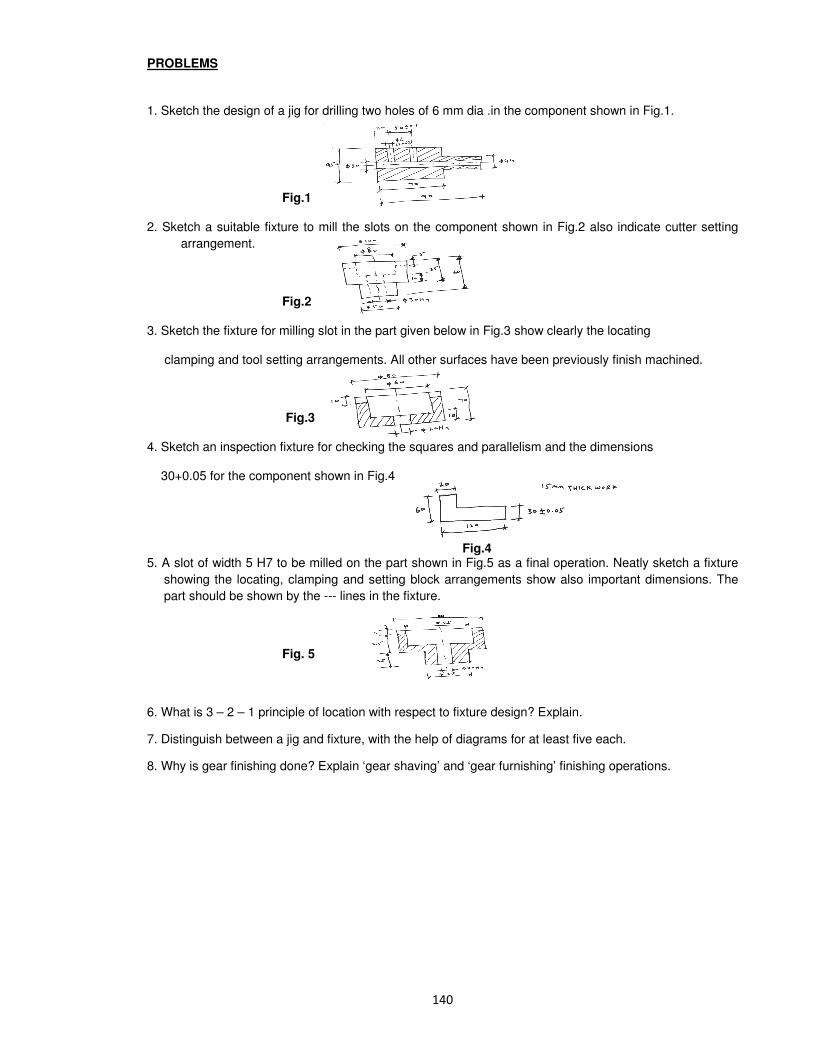
PROBLEMS
1. Sketch the design of a jig for drilling two holes of 6 mm dia .in the component shown in Fig.1.
Fig.1
2. Sketch a suitable fixture to mill the slots on the component shown in Fig.2 also indicate cutter setting
arrangement.
Fig.2
3. Sketch the fixture for milling slot in the part given below in Fig.3 show clearly the locating
clamping and tool setting arrangements. All other surfaces have been previously finish machined.
Fig.3
4. Sketch an inspection fixture for checking the squares and parallelism and the dimensions
30+0.05 for the component shown in Fig.4
Fig.4 5. A slot of width 5 H7 to be milled on the part shown in Fig.5 as a final operation. Neatly sketch a fixture
showing the locating, clamping and setting block arrangements show also important dimensions. The
part should be shown by the --- lines in the fixture.
Fig. 5
6. What is 3 – 2 – 1 principle of location with respect to fixture design? Explain.
7. Distinguish between a jig and fixture, with the help of diagrams for at least five each.
8. Why is gear finishing done? Explain ‘gear shaving’ and ‘gear furnishing’ finishing operations.
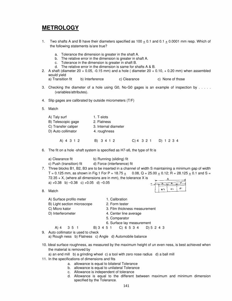
METROLOGY
1. Two shafts A and B have their diameters specified as 100 + 0.1 and 0.1 + 0.0001 mm resp. Which of
the following statements is/are true?
a. Tolerance the dimension is greater in the shaft A. b. The relative error in the dimension is greater in shaft A. c. Tolerance in the dimension is greater in shaft B. d. The relative error in the dimension is same for shafts A & B.
2. A shaft (diameter 20 + 0.05, -0.15 mm) and a hole ( diameter 20 + 0.10, + 0.20 mm) when assembled would yield
a) Transition fit b) Interference c) Clearance c) None of those
3. Checking the diameter of a hole using G0, No-G0 gages is an example of inspection by . . . . .
(variables/attributes).
4. Slip gages are calibrated by outside micrometers (T/F)
5. Match
A) Taly surf 1. T-slots
B) Telescopic gage 2. Flatness
C) Transfer caliper 3. Internal diameter
D) Auto collimator 4. roughness
A) 4 3 1 2 B) 3 4 1 2 C) 4 3 2 1 D) 1 2 3 4
6. The fit on a hole -shaft system is specified as H7-s6, the type of fit is
a) Clearance fit b) Running (sliding) fit
c) Push (transition) fit d) Force (interference) fit
7. Three blocks B1, B2, B3 are to be inserted in a channel of width S maintaining a minimum gap of width
T = 0.125 mm, as shown in Fig.1 For P = 18.75 + 0.08, Q = 25.00 + 0.12; R = 28.125 + 0.1 and S =
72.35 + X, (where all dimensions are in mm), the tolerance X is
a) +0.38 b) –0.38 c) +0.05 d) –0.05
8. Match
A) Surface profilo meter 1. Calibration
B) Light section microscope 2. Form tester
C) Micro kator 3. Film thickness measurement
D) Interferometer 4. Center line average
5. Comparator
6. Surface lay measurement
A) 4 3 5 1 B) 3 4 5 1 C) 6 5 3 4 D) 5 2 4 3
9. Auto collimator is used to check a) Rough ness b) Flatness c) Angle d) Automobile balance
10. Ideal surface roughness, as measured by the maximum height of un even ness, is best achieved when
the material is removed by
a) an end mill b) a grinding wheel c) a tool with zero nose radius d) a ball mill
11. In the specifications of dimensions and fits
a. allowance is equal to bilateral Tolerance b. allowance is equal to unilateral Tolerance c. Allowance is independent of tolerance d. Allowance is equal to the different between maximum and minimum dimension
specified by the Tolerance.

12. A fit is specified as 25 H8/e8. The tolerance value for a nominal diameter of 25 mm in IT8 is 33 m
and fundamental deviation for the shaft is –40 m. The maximum clearance of the fit in micros is
a) –7 b) 7 c) 73 d) 106
13. A slot is to be milled centrally on a block with a dimension of 40 + 0.05 mm. A milling cutter of 20 mm width is located with reference to the side of the block with in + 0.02 mm. The maximum offset in mm between the center lines of the slot and the block is
a) + 0.070 b) 0.070 c)+ 0.020 d) 0.045
14. Allowance in limits and fits refers to a) Max. clearance between shaft and hole b) Min. clearance between shaft and hole c) Difference between max. and min. size of hole d) Difference between max. and min. size of shaft
15. The dimensional limits on a hole of 25H7 are a) 25.000 25.21 mm b) 25.000, 24.979 mm
c) 25.000 25.007 mm d) 25.000 24.993 mm
16. The tolerance on 25H6 and 26H8 are 0.013 mm and 0.033 mm resp. The tolerance on 25.51 H7 is:
a) 21 mm b) 0.023 mm c) 30 m d) more of these
17. The process capability of a lathe is a) The max. diameter of the component that can be accommodated on the lathe. b) The max. prod. Rate from the lathe. c) The max. power available for machining d) The tolerance that is obtained on the parts produced on the lathe.
18. Four components P,Q,R and S with the tolerances as shown in fig. are assembled to make up a
dimension F.
P = 80.00 + 0.06 + 0.00
Q = 20.00 + 0.02
R = 25.00 + 0.08 - 0.02
S = 15.00 + 0.01
Using statistical tolerancing, the limits on the resultant dimension F are :
a) 140.06 + 0.062 b) 140.06 + 0.110 c) 14.00 + 0.110 d) 140.00 + 0.170 - 0.050
19. The best size of the wire used to inspect ISO metric thread of 4 mm pitch is
a) 2.000 mm φ b) 2.256 mm φ c) 2.309 mm φ d) 4.000 mm φ
20. A hole is specified on φ 35 H7 and size of tolerance zone is 0.025 mm. The axis of the hole is to be controlled with reference to A as shown in fig. A shoulder pin is used as a gauge for checking the geometrical relation. The pin size is
A) φ 34.925 mm b) φ 34.075 mm C) φ 35.05 mm d) φ 34.95 mm
21. A flange micrometer is used for measuring
A) Dimensions in narrow spaces B) The thickness of a spur gear tooth
C) The base pitch of a spur gear D) Diameter of a bore
22. Push (location) fit is used for:

A) Gears fixed on a shaft by means of a key
B) Shafts rotating at a slow speed in a journal bearing
C) Shaft rotating at a high speed in a journal bearing
D) Swinging parts such as the fit between gudgeon pin and the connecting rod of an automobile
engine.
23. With reference to the limits on the diameter of a hole, MMC means: a) Largest diameter of a hole b) Smallest diameter of a hole c) Mean diameter of a hole d) Positional relationship with the axis of the hole
24. A hole is specified as φ30 + 0.04 mm with -φ 0.01 M. The virtual diameter of the hole . . (I e the max.
dia. of the pin that can enter the hole) is . . . . .
25. Abbe’s principle of alignment is followed in:
a) vernier caliper b) Depth vernier
c) Internal caliper micrometers d) Height verniers
26. The diameter of a hole is given as 50 +0.15,+0.00 mm. The upper limit on the dimension in mm, of the
shaft for achieving the max. interference of 50 mm is . . . . .
27. The least count of a 200 mm long sprit level is given as 10 seconds per division. The gradient of the
spirit level expressed as mm over one meter is . . . . .
28. Vickers hardness test A) Steel ball is used as indentor and depth of penetration is measured.
B) Diamond pyramid indentor is used and diagonals of indentation is measured.
C) Diamond pyramid indentor is used and depth of penetration in measured.
D) Steel ball is used, indentor and diameter of the indentor are measured.
29. Match the following
Features to be inspected Instrument
P) Pitch and angle errors of screw thread 1. Auto collimator
Q) Flatness error of a surface plate 2. Optical interfe rometer
R) Alignment error of a M/C guide ways 3. Driving head and dial gage
S) Profile of cam 4. Sprit level
5. Sine bar
6. Tool maker’s microscope
A) P-6 Q2 R4 S6 B) P5 Q2 R1 S6
C) P6 Q4 R1 S3 D) P1 Q4 R4 S2
30. Instrument Principle of inspection
P. Dial indicator 1. Non contact
Q. Pneumatic gage 2. Limit of size
R. G0/N060 gage 3. Comparator
A) P2 Q3 R1 b) P3 Q1 R2 c) P1 Q2 R3 d) P2 Q1 R3
31. A dynamometer is a device used for the measurement of a. chip thickness ratio b. forces during metal cutting
c. wear of cutting tool d. deflection of the cutting tool
32. Process capability of a machine is defined as the capability of the machine to a. produce a definite volume of work per minute
b. perform definite number of operations
c. produce job at a definite spectrum of speed
d. hold a definite spectrum of tolerance and surface finish
33. Inter changeability can be achieved by a. standardisation b. better process planning c. bonus plan d. better product planning
34. What is standardisation? Give its four advantages

35. What are preferred numbers? Give their main advantages 36. Which of the following can be used in a dynameter for measuring cutting forces 1. strain gauge 2. Piezo electric transducer
3. pneumatic transducer 4. hydraulic transducer
a. 1 and 3 b. 2 and 3 c. 1 and 2 d. 2 and 4
37. The constant factor in case of R10 series of preferred numbers is a. 1.6 b. 1.25 c. 1.12 d. 1.03
38. Which grade symbol represents surface roughness for broaching a. N12 b. N6 c. N4 d. N1
39. A surface finish of 0.025 – 0.1 micrometer CLA value is to be produced, which machining process would you recommend
a. grinding b. rough turnining c. lapping d. honing
40. CLA value for Honing process is a. 6 b. 0.05 – 3.0 c. 0.05 – 1.0 d. 0.025 – 0.1
41. Which of the following would you prefer for checking the hardness of thin sections? a. Herbert cloud burst test b. shore’s scaloriscope
c. knoop hardness test d. vickers hardness test
42. Distinguish between unilateral and bilateral tolerances 43. How much surface roughness is denoted by the following
a. 50µm b. 25µm c. 12µm d. 6µm
44. Specify the ball size and the magnitude of load applied in case of Brinnell hardness tester in relation to load applied
a. 10D2 b. D
2 c. 5D
2 d. 2D
2
45. Match Measuring device Parameter measured
A. Diffraction grating 1. small angular deviations on long flat surfaces
B. Optical flat 2. on-line measurement of moving party
C. Auto collimator 3. measurement of gear pitch
D. laser scan micrometer 4. surface texture using interferometry
5. measurement of very small displacements
a. 4, 5, 1, 2 b. 5, 4, 1, 2 c. 1, 2, 4, 5 d. 2, 4, 1, 5
46. Using strain – gauge system for stress/force/displacement measurements how are in-built magnification and temperature compensation achieved?
47. Explain the difference between roughness and waviness 48. A medium force fit H7P6 is specified for an assembly of a hand wheel on a shaft of 50mm nominal
diameter. Calculate (i) the dimensions of hole (ii) the dimensions of shaft
(iii) maximum interference (iv) minimum interference
Given the following
Nominal size Limits of tolerance for P6 shaft in µµµµm
Over Upto and
includi
es
+
eI
+

ng
40 50 42 26
50 65 51 32
Limits of tolerance for H7 hole in µµµµm
es eI
30 50 25 0
50 80 30 0
49. Which one of the following tolerance set on inner diameter and outer diameter resp. of headed jig bush for press fit is correct
a. G7 h6 b. F7 n6 c. H7 h6 d. F7 j6
50. Calculate the fundamental deviation and tolerance and hence the limits of size for the shaft and hole for the following fit 64mm H8 – f7. The diameter steps are 50mm and 80mm. The shaft designation f, upper deviation is assumed as –5.5 D0.41
Data : for tolerance
H8 25 µ m
f7 16 µm The maximum clearance is
a. 0.030 b. -0.030 c.0.041 d. 0.071
51. How are unilateral and bilateral tolerances indicated on dimensions of a component? Illustrate each with an example
52. The gauge factor of a resistive pick up of cutting force dynamometer is defined as the ratio of a. applied strain to the resistance of wire
b. the proportional change in resistance to the applied strain
c. the resistance to the applied strain d. change in resistance to the applied strain
53. In an interchangeable assembly, shaft of size 25.000 –0.040, -0.010mm mate with holes of size 25.000 +0.020, -0.000mm. The maximum possible clearance in the assembly will be
a) 10 microns b) 20 microns c) 30 microns d) 60 microns
54. The pressure gages G1 & G2 installed on the system show pressures of PG1=5.00 bar & PG2=1.00 bar. The value of unknown pressure P is
a) 1.010 bar b) 2.01 bar c) 5.00 bar d) 7.01 bar
55. Go and NOGO plug gages or to be designed for a hole 20.000 +0.050, +0.010mm.Gage tolerance can be taken as 10% of the hole tolerance. Following I.S.O system of Gage design, sizes of GO and NOGO Gages will be respectively, in mm a) 20.010, 20.050 b) 20.014, 20.046 c) 20.006, 20.054 d)20.014, 20.054
56. The dimensional limits on a shaft of 25h 7 are a) 25.000,25.021 b)25.000, 24.979 c)25.000, 25.007 d)25.000, 24.993
57. A threaded nut of M 16, ISO metric type having 2mm pitch with a pitch diameter of 14.701mm, is to be checked for its pitch diameter using two or three numbers of balls or rollers of the following sizes. a) Rollers 2mm dia b) Rollers of 1.155mm dia
c) Balls of 2mm dia d) Balls of 1.155mm dia

58. Two slip gages of width 10mm measuring 1.000mm and 1.002mm are kept side by side in contact with each other length wise. An optical flat is kept resting on the slip gages as shown in fig. Monocromatic light of wave length 0.00058928 mm is used in the inspection. The total number of straight frings that can be observed in both slip gages is
a) 2 b) 6 c) 8 d) 13
59. The part shown in figure in machined to the sizes given below P=35.00 +0.08,-0.08mm
Q=12.00 +0.02, -0.02mm
R=13.00 +0.04, -0.02 mm
With 100% confidence, the resultant dimension W will have the specification
a) 9.99 +0.03, -0.03mm b) 9.99 +0.13, -0.13 mm c) 10.00 +0.03, -0.03mm
d) 10.00 +0.13, -0.13
60. During inspection of a M10 X 2.5 screw thread, the following observations were made Thread Number 1 2 3 4 5 Pitch Error +10 -2 -4 +8 -3 The cumulative pitch error for the thread is a) 1.8 microns b) 5.4 microns c) 9 microns d) 14 microns 61. A hole of diameter 25.00 +0.03,+0.01mm is to be inspected by using GO/NOGO gages. The size of
GO plug gage should be a) 25.000mm b) 25.01mm c)25.02mm d) 25.03mm
62. A metric thread with 2mm pitch and 60 0
thread angle is inspected for pitch diameter using 3 wire
method. The diameter of best wire is
a) 0.577mm b) 1.0mm c) 1.155mm d) 2.0mm
63. In an inter changeable assembly a shaft of 20.00 –0.015,-0.005 mm diameter and a hole of 20.00 +0.025, +0.010mm diameter form a mating pair. In worst assembly condition the clearance between them will be (in microns) a) 40 b) 30 c) 25 d) 15
64. In an interchangeable assembly, shafts of size 25.000 -0.040
-0.010
mm mate with holes of size 25.000 +0.020 -0.000
mm. The maximum possible clearance in the assembly will be
(A) 10 microns (B) 20 microns (C) 30 microns (D) 60 microns a. Match the following
Feature of inspected Instrument
P Pitch and Angle errors of screw thread 1. Auto Collimator
Q Flatness error of a surface plate 2. Optical Interferometer
R Alignment error of a machine sideway 3. Dividing Heat and Dial Gauge
S Profile of a cam 4. Spirit Level
5. Sine bar
6. Tool maker’s Microscope
(a) P-6 Q-2 R-4 S-6
(b) P-5 Q-2 R-1 S-6
(c) P-6 Q-4 R-1 S-3
(d) P-1 Q-4 R-4 S-2

66. In order to have interference fit, it is essential that the lower limit of the shaft should be
(a) greater than the upper limit of the hole (b) lesser than the upper limit of the hole (c)
greater than the lower limit of the hole (d) lesser than the lower limit of the hole
67. A ring gage is used to measure
(a) Outside diameter but not roundness (b) roundness but not outside diameter
(c) Both outside diameter and roundness (d) only external threads
0.050
68. A hole is specified as 400.000
mm. The mating shaft has a clearance fit with minimum clearance of
0.01mm. The tolerance on the shaft is 0.04mm. The maximum clearance in mm between the hole
and the shaft is
(a) 0.04 (b) 0.05 (c) 0.10 (d) 0.11
A gear set has a pinion with 20 teeth and a gear with 40 teeth. The pinion runs at 30 rev/s and
transmits a power of 20 kW. The teeth are on the 200 full-depth system and have a module of
5mm. The length of the line of action is 19mm.
69.. The center distance for the above gear set in mm is
(a) 140 (b) 150 (c) 160 (d) 170
70. The contact ratio of the contacting tooth is
(a) 1.21 (b) 1.25 (c) 1.29 (d) 1.33
71. The resultant force of the contacting gear tooth in N is
(a) 77.23 (b) 212.20 (c) 225.80 (d) 289
72. Which one of the following tolerances set on inner diameter and outer diameter respectively of headed dig bush for press fit is correct?
a. G 7 h6 b. F 7 n6 c. H 7 h6 d. F 7 j6
73. The value of surface roughness ‘h’ obtained during the tubing operating at a feed ‘f’ with a round nose tool having radius ‘r’ is given as
a. f /8r b. f2/8r c. f3/8r d. f3/8r2
74. In the tolerance specification 25 D 6, the letter D represents
a. Grade of tolerance b. Upper deviation c. Lower deviation d. Type of fit
75. Consider the following fits
1. I.C. engine cylinder and piston.
2. Ball bearing outer race and housing
3. Ball bearing inner race and shaft
Which of the above fits are based on the shaft basis system?
a. 1 and 2 b. 2 and 3 c. 1 and 3 d. 1, 2 and 3
76. Consider the following alignment tests on machine tools
1. Straightness 2. Flatness 3. Run out 4. Parallelism
Which of the above alignment tests on machine toots are common to both lathe and shaper?
a. 1 and 2 b. 2 and 3 c. 3 and 4 d. 1 and 4

77. The tolerance specified by the designer for the diameter of a shaft is 20.00 0.025mm. The shafts produced by three different of 19.99 mm, 20.00 mm and 20.01 mm respectively, with same standard deviation. What will be the percentage rejection for the shafts produced by machines A, B and C?
a. Same for the machines A, B and C since the standard deviation is same for the three machines
b. Least for machine A
c. Least for machine B
d. Least for machine C
78. Assertion (A): Hole basis system is generally preferred to shaft basis system in tolerance design for getting the required fits.
Reason (R): hole has to be given a larger tolerance band than the mating shaft.
a. Both A and R are individually true and R is the correct explanation of A
b. Both A and R are individually true but R is not the correct explanation of A
c. A is true but R is false
d. A is false but R is true
79. Which of the following is an interference fit?
a. Push fit b. Running fit c. Sliding fit d. Shrink fit
80. The M and E-system in metrology are related to measurement of :
a. screw threads b. flatness c. angularity d. surface finish
81. In strain gauge dynamometers, the use of how many active gauges makes the dynamometer more effective?
a. Four b. Three c. Two d. One
82. Which one of the following is a clearance fit?
+ 0015 -0.010
+ 0005 + 0.000
a. H 50 h 50
+0.010 -0025
+0.000 +0.015
b. H 50 h 50
-0015 +0.025
+ 0.000 +0.005
c. H 50 h 50
- 0010 + 0030
- 0000 +0.005
d. H 50 h 50
83. What is the dominant direction of the tool marks or scratches in a surface texture having a directional quality called?
a. Primary texture b. Secondary texture c. Lay d. Flaw

84. Consider the following statements:
1. The amount of interference needed to create a tight joint varies with diameter of the shaft.
2. An interference fit creates no stress state in the shaft.
3. The stress state in the hub is similar to a thick-walled cylinder with internal pressure.
Which of the statements given above are correct?
a. 1, 2 and 3 b. 1 and 2 only c. 2 and 3 only d. 1 and 3 only
85. Consider the following statements:
A nomenclature 50 H8/p8 denotes that
1. hole diameter is 50 mm.
2. it is a shaft base system.
3. 8 indicates fundamental deviation.
Which of the statements given above is/are correct?
a. 1, 2 and 3 b. 1 and 2 only c. I and 3 only d. 3 only
86. Assertion (A): In centralized inspection, material handling is less.
Reason (R): Less number of gauges and instruments are required as inspection is carried out in one location.
87. Assertion (A): Elements are classified into metals and non-metals on the basis of their atomic weights.
Reason (R): The valence electron structures contribute to the primary bonding between the atoms to form agregates
88. What term is used to designate the direction of the predominant surface pattern produced by machining operation?
a. Roughness b. Lay c. Waviness d. Cut off
89. What symbol is used to indicate surface roughness?
a. = b. c. 0.1 d.

PROBLEMS
1. Calculate the CLA (Ra) value of surface roughness for which the sampling length was 0.8mm. The
graph was drawn to a vertical magnification of 10,000 and a horizontal magnification of 100, and the
areas above and below the --- line were
above: 150 80 170 40 mm2
below: 80 60 15 120 mm2
2. In the measurement of surface roughness, heights of 20 successive peaks and troughs used measured from a datum and were 35,25,49,22,35,8,42,25,32,22,36,18,42,22,32,21,37,18,35,20 If these measurements were obtained over a length of 20mm determine the cla (Ra) and rms value of
the rough surface.
3. Calculate the Ra value of the surface for which the samples length was 8.0mm, the graph was drawn
to a vertical magnification of 1000 and the are above and below the datum line are
above 180 90 155 55 mm2
below: 70 90 170 150 mm2
4. Derive an expression for the best size wire.
5. Explain why it is preferred not to use a sine bar for generating angles larger than 450 if high accuracy
is demanded.
6. In setting a sine bar of 125mm length to an angle of 30 degrees what errors will be introduced if :
(i) The assumed 125mm roller separation is actually 125.005mm.
(ii) The upper cylinder of sine bar is 0.002mm bigger than the actual size
(iii) gaging face of the bar is out of parallel from rollers by +0.02mm.
(iv) The slip gages used have an unsuspected error of 0.005mm
(v) All errors are present together.
7. A100mm sine bar is to be set up to an angle of 32.50 determine the slip gauges needed. estimate the
error in angle if.
(i) distance between rollers is not correct by +-0.01 mm
(ii) If dia. of rollers is out by +0.005mm
(iii) if error of parallelism between top surface and line joining center of roller is +0.02mm
(iv) if all the these errors exist simultaneously.
8. Calculate the limits of tolerance and allowance for a 25mm shaft and hole pair designated H8d9
FD for d shaft : -16D 0.44
9. Calculate the dimensions of plug and ring gages to control the production assumptions may be made:
50mm is in the diameter step of 30 and 50mm and the upper deviation for ‘d’ shaft is -16D 0.44 and
lower deviation for hole H is zero I = 0.45 D1/3 +0.0001D and IT6=10µm 10 .Design the “General” type “Go” and “Not go” gages of components having 25H7 f 8 fit being with used
notations:
(i) i = 0.45 (D )1/3
+ 0.001 (ii) upper deviation for f shaft -5.5 D 0.41
(iii) 25mm falls in the diameter stops of 18 and 30. take wear allowance as 10% of guage tolerance.
11. Determine the dimensions and tolerance of shaft and hole having size of 30h7/H8 fit. Also determine
the allowance (i.e. minimum clearance) and max. Clearance.
12. Design and sketch working plug and snap ‘Go’ and ‘NO GO’ gages for spindle of 30.98./30.960 and hole of 31.023/31.000

13. A 60mm m6 shaft is to be checked by a GO, not-go snap gauge. Assume 5% war allowance and
10% gauge maker’s tolerance (% if tolerance is shaft). The fs for m fit is (IT7-IT6). Sketch workshop,
inspection GO- gauges.
14. Explain the symbols in the box above the fig.?
15. A beam comparator was used along the lines AB and CD where AB and CD are equal in length.
The mid point C was 10mm below and the mid point E was 10mm above with reference to the end
points, What is the floating error with reference to above ABD.?
16. A flat plate with two pairs and another flat plate with two holes have to be assembled with the pins
entering the holes as shown in fig.
(a) Assuming that the pins touch the outermost points of the holes as shown, find the limits on the
center distance between the holes with the help of a sketch showing the dimensional chain.
(b) What will happen to the center distance between the holes, when the size of the holes and the
center distance between pins are at their max. Limits and pin sizes at the minimum limits, will the
assembly be possible?
17. A machine operator needs a gauge for checking the diameter of holes being machined to diameter
20.000 +0.06,-0.04 mm. What should be the dimensions (diameter) of the gauge if unilateral system
of balances are incorporated ? Assume gauge tolerance and wear allowance each as 10% of work
tolerance.
18. Mention which angle gauges will be used to make an angle of 70 56 1 the angle so obtained, is
checked with a sine bar of length 250mm.What slip gauge combination will be reqd.
19. Straightness measurement is carried out using a device shown below.

Initially the device is kept on a flat surface and the dial is set to zero on the test surface, the following
reading are obtained (1 dim =10mm)
Position 1 2 3 4
Reading +2 0 -1 +1
(a) Sketch the straightness deviation using the above readings.
(b) Calculate the straightness error using end points reference line.
20. Calculate, using base tangent method the theoretical distance between two parallel, measuring faces
over 3 teeth on a spur gear of 30 teeth 3mm module and 200 pressure angle.
21. A 100mm size sine bar is used to find the included angle of a plug gauge is shown in fig. below . The
height of the slip gauges below the lower cylinder is 25mm.
(a) If the angle is 30o what is the height of slip gauges below the upper cylinder.
(b) What would the height of the slip gauges below the upper cylinder be if the length of the sine bar
was 100.005mm and the upper cylinder 0.005mm larger?
22. A sine bar and a set of gauge blocks (slip gauges) and used to measure the angles of tapered
components neglecting errors due to the use of slip gauges, prove that sine bar achieves great
accuracy while measuring smaller angles than while measuring larger angles.
23. (a) How do we get an estimate of the magnitude of deviations from straightness of surface using a
straight edge?
(b) A surface was checked for straightness along a line 600mm long using a spirit level of 100mm base length. Successive reading are given below.
Range 0-1 1-2 2-3 3-4 4-5
Land reading +10 n +15n +10n -10n -15n
What is the mean deviation from straightness of this surface?

24. Fig. shows 3-wire method of inspecting screw threads. Assuming ISO metric threads of size M16 with
pitch =2mm and effective diameter =14.701mm. determine the over write measurement S when the
diameter of the roller used for the measurement is 1.155mm. The diameter of the roller
correspondence to the best wire size for which the roller touches the thread flanks at points created
along the effective diameter.
25. Balls diameter 30mm and 15mm used to measure the taper of a ring gauge. during inspection the
ball of 30mm dia. was protruded by 2.5mm above the top surface of the ring, This surface was
located at a hight of 50mm from the top of the 15mm dia ball calculated taper angle.
26. The bore diameter, D of a plain ring having a height of 35mm was measured using two spherical
balls, each of diameter d=25.000mm .The ring was placed on a surface table and then both the balls
were placed inside the ring. In this position, the height h of the top of the upper ball from the surface
table was found to be 42.000mm
(a) Derive the expression for D in terms of d and h
(b) What is the bore diameter, D of the ring?
27. A square plate is inspected for flatness. The flatness, the reading obtained, using and electronic
gauge, on a grid of 1mm X 1mm are as follows. A=40.005mm B=40.010mm C=40.015mm
D=40.000mm where M is at the grid center as shown in fig...
(a) Give the equation of the assessment plane passing through ABD with origin at A and coordinate axes along A-B and AD.
(b) Using the above assessment plane find the deviation of C and M and arrive at the
flatness error (in µm)
28. The fig. shows the position of two holes on the face of a casting 250+ 0.2 mm high . Considering the
extreme values of the dimensions
(a) find the vertical distance between the holes and its tolerance
(b) Calculate the tolerance on X (=40mm)
Tolerance on 30H7 AND 25H7 is 0 to 21µm
29. Calculate the fundamental deviation and tolerance and hence the limits of size for the shaft and hole
for the following fit 64 mm H8-f 7. The diameter steps are 50 mm and 80 mm. For shaft designation f,
upper deviation is assumed as –5.5 D0.41 :– Data : For tolerance H 8 25 if 7 16i (10)

30.Find the limit sizes, tolerances arid allowance for a 100 mm diameter shaft and hole pair designated by
F8h10 . Also specify the type of fit that the above pair belongs to. Given : 100 mm diameter lies in the
diameter step range of 80-120 mm. The fundamental deviation for shaft designation ‘f’ is –55 D0.41. The
values of standard tolerances for grades of 1T8 and 1T10 are 25i and 64i respectively. Also, indicate the
limits and tolerance on a diagram.
31. Name the instruments by which diameter of machined circular holes can be measured and mention
their application capabilities in terms of precision and diameter range.
32. Explain the working principle of Hot-wire Anemometry to measure the velocity of fluid with the help of a
sketch.
33. What do you understand by ‘Selective Assembly’ process? How is the range of clearance reduced?
(p) What is the principle of angle dekkor auto collimator? What is its application?

NC, CNC, CIM
1. In thermal power plants, coal is transferred from bunker to the other places by a. hoist b. conveyors c. cranes d. lifts
2. Which of the following drive system is used in CNC machine tools? a. stepper motor b. low frequency electric motor
c. thyristor controlled DC motor d. servo controlled pneumatic drives
3. A ‘block’ of information in NC machine program means a. one row on tape b. a word comprising several rows on tape
c. one complete instruction d. one complete program for a job
4. Match Equipment Application
A. Hist 1. For moving over a fixed route
B. Conveyor 2. For transporting material over a varying path
C. Fork truck 3. For vertically raising or lowering material in a fixed location
D. Elevator 4. For over head lifting of loads in a fixed area
5. For moving persons up and down
a. A-4,B-1,C-3,D-5 b. A-1,B-4,C-3,D-5 c. A-3,B-5,C-4,D-1 d. A-5,B-3,C-4,D-1
5. List 4 advantages of numerical control 6. Differentiate between the decimal and binary code systems. Find the decimal and binary codes for the
number 140 7. Feed drives in CNC milling machines are provided by
a. synchronous motors b. induction motors c. stepper motors d. servo motors
8. In a transfer line
a. all the machine tool must be automatic
b. the work stations must form a closed-loop
c. the cycle time if total taken by all the machining operations
d. all the machine tools must be conventional and general purpose type
9. A device used for lifting or lowering objects suspended from a hook at the end of retractable chains
or cable is called
a. hoist b. jib crane c. portable elevator d. chain conveyor
10. In APT language, the cutter motion in incremental coordinate mode is addressed as
a. GOTO /.... b. GO/TO…. c. GODLTA /.... d. GO FWD/....
11. In a computer application where a direct dialogue is carried on between the computer and the user is
referred to as
a. interfacing b. batch processing c. decision d. real-time application
12. Expand the abbrevations : (i) DNC (ii) CNC
13. In manual part programming for a NC drilling machine, the spindle speed was coded as S 684 (using
the magic three codes) The spindle speed in rpm will be
a. 684 b. 68.4 c. 840 d. 6840
14. Which of the following pairs are correctly matched
1. CNC machine – port processor
2. Machining center – tool magazine
3. DNC – FMS
a. 1 and 3 b. 1 and 2 c. 1 and 3 d. 1,2 and 3
15. Which of the following is/are the advantage(s) of numerical control of machine tools?
1. reduced lead time 2. consistently good quality 3. Elaborate fixtures are not required
a. 1, 2 and 3 b. 1 and 3 c. 2 and 3 d. 1 and 2
16. A) NC machines having more than three axes do not exist T/F
R) There are only three Cartesian coordinates namely x-y-z. T/F
17. A) Special purpose machine tools and automatic machine tools are quite useful for job shops
T/F
R) Special purpose machine tools can do special types of machining work automatically T/F
18. What is a compiler in a computer?

19. Describe briefly the operation of a machining center
20. Which of the following are valid statements for point to point motion of the tool in APT language?
1. GOTO/..... 2. GO DLTA/..... 3. GO/TO/...…
Select the correct answer
a. 1 & 2 & 3 b. 1 & 2 c. 1 & 3 d. 2 & 3
21. Match
Track numbers on paper type Holes on these tracks represents
A. Track no. 1 to 4 1. Alphabets
B. Track no. 5 2. Numerals
C. Track no. 6 and 7 3. End of Block
D. Track no. 8 4. parity check
a. 2 3 1 4 b. 4 1 3 2 c.1 2 3 4 d.2 4 1 3
22. Define the following statements as given in APT language
(i) C1 = CIRCLE / CENTRE, P1 TANTO, LI
(ii) FEDRAT / 4.0
23. Name two important constituents of CPU in a computer
24. What is a DNC system in manufacturing? What are the basic computers
25. Consider the following criteria in evaluating machinability
1. surface finish 2. type of chips 3. tool life 4. power consumption
In modern high speed CNC machining with coated carbide tools, the correct sequence of these criterion in decreasing order of their importance is
a. 1, 2, 3, 4 b. 1, 3, 4, 2 c. 2, 4, 3, 1 d. 4, 3, 2, 1
26. In tape preparation for an NC machine tool, the code S624 would represent spindle speeds of
a. 624 rpm b. 6240 rpm c. 264 rpm d. 162.4 rpm
27. Which of the following are the rules of programming NC machine tools in APT language?
1. only capital letters 2. a period is placed at the end of each statement 3.insertion of space does not affect the APT word.
a. 2 and 3 b. 1 and 2 c. 1 and 3 d. 1, 2 and 3
28. Multiple coated, disposable carbide tips have more-or-less replaced brazed carbide tipped tools in
CNC applications why?
29. Consider the following components
1. a dedicated computer 2. bulk memory 3. telecommunication lines
Which of these components are required for a DNC a. 2 and 3 b. 1 and 3 c. 1 and 2 d. 1,2 and 3
30. Transfer machines can be defined as
a. material processing machines b. material handling machines c. material processing and handling machines d. component feeder for automatic assembly
31. Which of the following statements regarding NC machine tools
1. they reduce non-productive time 2. they reduce fixturing 3. they reduce maintenance cost
Which of the statements are correct
a. 1 and 3 b. 1 and 2 c. 2 and 3 d. 1,2 and 3
33. Describe two distinguishing features of Robots, which make them different from conventional material handling equipment
34. A part program is to be written to drill the holes in the work part shown below. The part is 10mm-
thick. The dia of drill is φ10.0 shown in fig 1
35. A) The axis of a NC drilling machine spindle is denoted as z-axis T/F
R) In NC machine tool, the axis is to both x-and y-axis is designated as z-axis T/F
36. Match

A. RAM 1. Network of computers
B. ROM 2. Software which makes the computer to work
C. DOS 3. Memory used for processing
D. LAN 4. Memory in which user cannot write anything
a. A-3,B-4,C-2,D-1 b. A-4,B-3,C-2,D-1 c. A-2,B-1,C-3,D-4 d. A-1,B-4,C-3,D-2
37. Name 4 parts of feeding devices in automation
Explain the functions of the four components of FMS
38. Indicate the situation where FMS is preferred as compared to transfer lines
39. During manufacturing of cement, the handling of lime stone is done by
a. belt conveyor b. bucket conveyor c. over head conveyor d. fork-lift conveyor
40. Distinguish between computer education and computerized education
41. What is JIT? What is the primary benefit derived from its adoption
42. What is concurrent engineering?
43. Explain the difference between hard and soft automation? Why are they so called?
44. What are the features of an intelligent robot? 45. In a PTP NC system
b) Control of position and velocity of the tool is essential c) Control of only position of the tool is sufficient d) Control of only velocity of the tool is sufficient e) Neither position nor velocity need be controlled.
46. With reference NC machines, which of the following statement in wrong.
a) Both closed, loop and open-loop systems are used b) Paper tapes, floppy tapes and cassettes are used for data storage c) Digitizers may be used as interactive input devices. d) Post processor in an item of hard ware.
47. CNC machines are more accurate than conventional machines because they have a high resolution
encoder and digital read outs for positioning. (T/F)
48. CNC machines are more economical to use even for simple turning jobs. (T/F)
49. In PTP NC machine, the slides are positioned by an integrally mounted stepper motor drive. If the
specification of the motor is 1o/pulse, and the pitch of the lead screw is 3.6 mm, what is the
expected positioning accuracy?
a) 1 µm b) 10 µm c) 50 µm d) 100 µm
50. In computer aided drafting practice, an arc is defined by
a) Two end points only b) Center and radius
c) Radius and one end point d) Two end points and center
51. Cellular manufacturing is suitable for
a) A simple product in large volumes b) One-off production of several varieties c) Products with similar features made in batches d) Large variety of products in large volumes
52. In finish machining of an island on a casting with CNC milling machine, an end mill with 10 mm
diameter is employed. The corner points of the island are represented by (0,0), 0,30), (50,30),
(50,0). By applying cutter radius right compensation, the trajectory of the cutter will be.
a) (-5,0), (-5,35), (55,35), (55,-5), (-5,-5) b) (0,-5), (55,-5), (55,35), (-5,35), (-5,-5) c) (5,5), (5,25), (45,25), (45,5), (5,5) d) (5,5), (45,5), (45,25), (5,25), (5,5)
53. In an NC machining operation, the tool has to be moved from point (5,4) to point (7,2) along a
circular path with center at (5,2). Before starting the operation, the tool is at (5,4). The correct 6
and M code for this motion is
A) N010 G03 X7.0 Y2.0 I5.0 J2.0
b) N010 G02 X7.0 Y2.0 I5.0 J2.0
C) N010 G01 X7.0 Y2.0 I5.0 J2.0
D) N010 G00 X7.0 Y2.0 I5.0 J2.0
54. Axes-drives in machining centers are:
a) AC synchronous motor b) DC servo motor
c) Stepper motor d) Induction motor
55. Concurrent engineering applied to project management.

a) Performs the stages one after the other b) Minimizes the no.of stages by combining where ever possible c) Performs the stages simultaneously d) Minimizes the budgetary allocations
56. A DC servo motor is directly driving an NC table. The pitch of the lead screw of the table is 5 mm.
The motor rotates at 100 rpm for an applied voltage of 10 v If the voltage-speed characteristics of
the motor is linear the applied voltage for a table speed of 3 m/min is equal to:
A) 30V B) 60V C) 33V D) 50V
57. GET in MTM-2 is equivalent to the following in MTM-1:
a) Reach, Move, Release b) Reach, group, position
c) Reach, group, move d) Reach, grasp, release
58. Machining of complex shapes on CNC machines requires
A) Simultaneous control of x,y and z axes
B) Simultaneous control of x and y axes
C) Independent control of x and y axes
D) Independent control of x,y and z axes
59. Concurrent engineering is an approach
a) Where product design proceeds at the same time as process design b) Where product design and facilities lay out are carried out. c) To reduce variety in manufacturing a group of parts d) To eliminate complex design features with a view to reduce costs
60. Which of the following statements do not hold good for CNC machines?
a) Feed back control system is essential b) Operate on tape input c) Can be employed for either machining or inspection d) Require a dedicated computer for each machine
61. FMS is well suited to mass scale manufacturing (T/F)
62. In DNC each machine tool is controlled by a dedicated computer (T/F)
63. FAPT is a part programming language (T/F
64. Just-in-time (JIT) is a pull type system of production planing.
65. During the execution of a CNC part program block N 020 G02 X45.0 Y25.0 R5.0 the type of tool
motion will be
A) circular interpolation –clock wise
B) Circular interpolation – ccw
C) Linear interpolation
D) Rapid feed
66. The function of an interpolator in a CNC machine controller is to provide
A) Spindle speed control
B) Position feed back and control
C)Feed drive coordination and control
D)On/Off relay control
67. Group 1 Group 2
P)Automatic lathe 1) Simultaneous control of several machines
Q)CNC 2) Batch production of a family of parts
R)FMS 3) Mass production of single variety of parts
S)DNC 4) Flexible control of single machine tool
A)1 2 3 4 B)3 4 1 2 C)3 4 2 1 D)3 2 4 1
68. Group 1 Group 2
P.Manufacturing of dies 1.Product lay out
Q.Manufacture of family of gears 2.Process lay out
R.Manufacture of steel sheets 3.Cellular point
S.Manufacture of cylinder blocks 4.Trasfer line
A)2 3 1 4 B)4 3 2 1 C)1 4 2 3 D) 3 2 4 1
69. During the execution of CNC part program block N020 G02 X 45.0 Y 25.0 R 5.0, the type of tool motion will be
(A) Circular interpolation- clock wise (B) Circular interpolation- counter clock wise (C) Linear interpolation (D) Rapid feed

70. In a 2-D CAD package, clockwise circular are of radius 5, specific from P1 (15, 10) to P2 (10, 15) will
have its center at
(a) (10, 10) (b) (15, 10) (c) (15, 15) (d) (10, 15)
71. The tool of an NC machine has to move along a circular arc from (5, 5) to (10, 10) while performing an
operation. The centre of the arc is at (10, 5). Which one of the following NC tool path commands
performs the above mentioned operation?
(a) N010 G02 X10 Y10 X5 Y5 R5 (b) N010 G03 X10 Y10 X5 Y5 R5
(c) N010 G01 X5 Y5 X10 Y10 R5 (d) N010 G02 X5 Y5 X10 Y10 R5
72. NC contouring is an example of
(a)continuous path positioning (b) point-to-point positioning
(c) Absolute positioning (d) incremental positioning
73. Which among the NC operations given below are continuous path operations?
Arc Welding (AW) Milling (M)
Drilling (D) Punching in Sheet Metal (P)
Laser Cutting of Sheet Metal (LC) Spot Welding (SW)
(a) AW, LC and M (b) AW, D, LC and M
(c) D, LC, P and SW (d) D, LC, and SW
74. Which type of motor is NOT used in axis or spindle drives of CNC machine tools?
(a) Induction motor (b) dc servo motor (c) stepper motor (d) linear servo motor
75. Consider the following characteristics of a robot:
1. The tip of the robot arm moves from one point to another with it’s in between path not being defined.
2. it can be used for drilling holes at different points in a work piece.
3. It can be used for V butt joint welding between two points.
4. The memory capacity required for its control unit is low. Which of these are the characteristics associated with a point to point robot?
a. 1 and 2 b. 1, 3 and 4 c. 1, 2 and 4 d. 2, 3 and 4
76. match List I with List II and select the correct answer:
List I
A. RAM B. ROM C. DOS D. LAN
List II
1. Network of computers 2. Software which makes the computer work
3. Memory used for processing 4. Memory in which user cannot write anything
Codes; A B C D
a. 1 2 3 4 b. 3 4 2 1 c. 2 3 4 1 d. 3 4 1 2
77. Assertion (A): The axis of an NC drilling machine spindle is denoted as z - axis.
Reason (R): In NC machine tool, the axis perpendicular to both x- and y - axes is designated as z - axis.
a. Both A and Rare true and R is the correct explanation of A
b. Both A and R are true but R is NOT the correct explanation of A
c. A is true but R is false
d. A is false but R is true
78. During manufacture of cement, the handling of limestone is done by
a. belt conveyor b. bucket conveyor c. overhead crane d. fork-lift crane
79. In a CNC machine tool, encoder is used to sense and control

a. Table position b. Table velocity c. Spindle speed d. Coolant flow
80. Match List I with List II and select the correct answer:
List I (NC machine tool system)
A. NC system B. CNC system C. DNC system D. Machining centre
List II (Features)
1. It has an integrated automatic tool changing unit and a component indexing device
2. A number of machine tools are controlled by a computer. No tape reader, the part programme is
transmitted directly to the machine tool from the computer memory
3. The controller consists of soft-wired computer and hard-wired logic system. Graphic display of tool path is also possible
4. The instructions on tape is prepared in binary decimal form and operated by aseries of coded instructions
A B C D
a. 4 2 3 1 b. 1 3 2 4 c. 4 3 2 1 d. 1 2 3 4
81.While part programming in CNC machines, the input of dimensional information for the tool path can be given in the absolute co-ordinate system or in incremental coordinate system. The above figure shows the route to be followed by the tool from 0 to C, i.e., 0 – A – B – C. If incremental coordinate system is used, the co-ordinates of each point A, B and C are
a. A : X 5.0, Y 10.0 B : X 20.0,Y 5.0 C : X 10.0, Y – 10.0
b. A : X 5.0, Y 10.0 B : X 25,Y 15.0 C : X 35,Y 5.0
c. A : X 10.0, Y 5.0 B : X 15.0, Y 25.0 C : X 5.0,Y 35.0
d. A : X 10.0, Y 5.0 B : X 5.0,Y 20.0 C : X 10.0, Y 10.0
82. Consider the following characteristics
1. Single machine tool 2. Manual materials handling system
3. Computer control 4. Random sequencing of parts to machines
Which of the above characteristics are associated with flexible manufacturing system?
a. 1, 2 and 3 b. 1 and 2 c. 3 and 4 d. 2, 3 and 4
83. Which item best describes a CAM technology?
a. Geometric modeling b. Documentation c. Drafting d. Numerical control
84. Flexible manufacturing allows for:
a. tool design and production b. automated design
c. quick and inexpensive product change d. quality control
85. Which one of the following is the third basic component of robots besides power supply and control (memory) console?
a. Software b. Coaxial cable c. Mechanical unit arm d. Microcomputer
86. What are the main components of an NC machine?
1. Part program 2. Machine Control Unit 3. Servo meter
Select the’ correct answer using the code given below

a. 1, 2 and 3 b. 1 and 2 only c. 2 and 3 only d. 1 and 3 only
87. Explain the difference between hard and soft automation. Why are they so called?
88. What is meant by Basic Length Unit (BLU) of CNC machine tools? Determine the BLU of a CNC
machine tool whose work-table is moved by a 4 mm pitch lead screw driven by a stepper motor having 200
steps in one rotation/revolution.
89. Define NC, CNC and DNC. Also explain their developments, and improvements in their applications.
90.What is meant by ‘interpolation in CNC programming’ ? What for are ‘G’ and ‘M’ codes used in NC part
programming?
91. Prepare a part program for machining a rectangular contour of 200 mm 100 mm size from a suitable
MS blank of 5 mm thickness. Also, a reamed hole of 16 mm has to be made centrally in the rectangular
contour. Take speeds and feeds arbitrarily.
92.Prepare part program to machine the contour shown in the figure using APT on CNC milling machine.
Material : MS Thickness : 80 mm
Prepare part program using APT language for milling the contour shown in Fig. in a single pass.
93. Explain the functions of the four components of Flexible Manufacturing System. Indicate the situation
where FMS is preferred as compared to Transfer lines.
94. What are the characteristics of cellular manufacturing system?
95. Name four parts of feeding devices in automation.
96. What is concurrent engineering?
97. What is JIT ? What is the primary benefit derived from its adoption?
98. What are the feature of an intelligent robot ?

METALLURGY
1. Carburised machine components have high endurance limit because carburisation
a) Raises yield point of the material b) Produces a better surface finish c) Introduces a compressive layer on the surface d) Suppresses any stress concentration produced in the component.
2. Match
a) Pearlite 1. Extremely hard and brittle phase
b) Martensite 2. Cementite is finely dispersed in Ferrite
c) Austenite 3. Alternate layers of cementite and Ferrite
d) Eutectoid 4. Can exist only above 723oC
5. Pertaining to state of equilibrium between one liquid and two solid phases
a) 2 1 4 3 b) 1 2 4 5 c) 2 1 3 4 d)4 5 2 1
3. The iron – carbon diagram and TTT curves are determined under
a) Equilibrium and non-equilibrium conditions resp. b) Non-equilibrium and equilibrium conditions resp. c) Equilibrium conditions for both d) Non-equilibrium conditions for both
4. The alloying element mainly used to improve the endurance strength of steel material is
a) Ni b) V c) Mo d) W
5. On completion of heat treatment, the resulting structure will have retained austenite if a) Rate of cooling is greater than the critical cooling rate b) Rate of cooling is less than the critical cooling rate c) Martensite formation starting temp. is above the room temp. d) Martensite formation finish temp. is below the room temp.
6. Decreasing grain size in a poly crystalline material
a) Increases yield strength and corrosion resistance b) Decreases yield strength and corrosion resistance c) Decreases yield strength but increases corrosion resistance d) Increases yield strength but decreases corrosion resistance
7. Cast steel crank shaft is hardened by
a) Nitriding b) Normalising c) Carburising d) Induction heating
8. In descending order of magnitude, the thermal conductivity of
a) Pure iron b) Liquid water c) Saturated water vapor d) Pure AC
A) abcd B) bcad C) dabc D) dcba
9. The ductility of a material with work hardening
a) Increases b) Decreases c) Remains unaffected d) Un predictable
10. During heat treatment of steel, the hardness of various structures in increasing order is
a) Martensite, fine pearlite, coarse pearlite, spherodite. b) Fine pearlite, coarse pearlite, spherodite, martensite c) Martensite, coarse pearlite, fine pearlite, spherodite d) Spherodite, coarse pearlite, fine pearlite, martensite
11. Hardness of steel greatly improves with
a) Annealing b) cyaniding c) normalizing d) tempering

12. The maximum solubility of carbon in austenite in an Fe-C system is close to:
a) 0.02% b) 0.80% c) 2.04% d) 4.27%
13. The diagram in fig. Shows binary equilibrium diagram of an alloy of X in Y
An alloy containing P% of X is allowed to solidify from a temp. Tp. At temp. T the fraction of solid
formed is
a) AC b) BC c) AC d) BC
BC AB AB AC
14. The following are six materials belonging to thermo set and thermo-plastic groups:
1) Epoxy 2) Poly ethylene 3) Bakelite 4) Poly styrene 5) Polyesters 6) PVC
The materials which belongs to thermo plastic group are:
a) 1,2,4,6 b) 3,5 c) 2,4,5,6 d) 2,4,6
15. In iron-carbide diagram, pearlite is
b) Eutectoid mixture of austenite and ferrite c) Eutectoid mixture of cementite and ferrite d) Eutectic mixture of austenite and cementite e) Eutectic mixture of austenite and ferrite
16. The capacity of a material to with stand plastic deformation in compression without fracture is
known as
f) Toughness b) Ductility c) Malleability d) Resilience 17. Normalizing of steel is done by
a) Leaving in the open yard for 6 months to 2 years b) Heating below critical temp. followed by air cooling c) Heating above critical temp. followed by air cooling d) Heating above critical temp. followed by furnace cooling
18. Al-alloy is employed for transportation applications primarily because of its:
a) Low density b) High strength c) High strength to wt ratio d) High toughness
19. Mg. is extruded and not rolled because it has:
a) Low melting point b) Low density
c) High vapour pressure d) Close packed hexagonal structure
20. Ni and Co base alloys are most effectively employed in an environment of
a) high temp b) Corrosion c) High stress d) Combined stress, corrosion and temp.
21. Carbon equivalent of general purpose gray CI is approximately:
a) 2.6 b) 4.2 c) 3.6 d) 4.7
22. The carbon content of MS can be
a) 0.15% b) 0.51% c) 0.8% d) 1.8%
23. Tool steels are quenched and tempered to impart
a) High hardness b) High toughness c) combined hardness & toughness d) High strength

24. The final heat treatment given to a forging die is:
a) process amending b) Hardening and tempering
c) Normalizing and stress relieving d) Homogenising
25. The hardness testing method which does not involve resistance to plastic deformation is:
a) Shore scalori scope b) Brinnel c) Rock well d) vicker
26. Inoculation of high duty CI melts is to
a) Reduce chilled structure b) Degas the melt
c) Produce white iron d) Improve mech. Properties
27. Ti in small quantities is added to Al-cu alloys before pouring for the purpose of :
a) Degassing b) Grain refinement c) Modification d) Reducing density of the alloy
28. Steel is melted in the foundry in a
a) Reverbaratory furnace b) Arc furnace c) Induction furnace d) Crucible furnace
29. Coke to metal ratio in the charge of a cold blast cupola operating with indigenous high ash coke is
of the order of
A) 1:5 B) 5:1 C) 1:10 D) 10:1
30. The structure of HSS is :
A) Micro carbides in an austenite matrix B) Metallic carbides cemented together
C) Mertensite matrix with a fine dispersion of carbides D) Iron carbide in a matrix of pearlite
31. The correct sequence of materials arranged in the order of decreasing hot hardness is
a) Ceramics, carbides, HSS, carbon tool steels b) Carbon tool steels, carbides, ceramics, HSS c) Ceramics, HSS, Carbides, carbon tool steel d) Carbon tool steels, HSS, carbides, ceramics
32. Full annealing is a process in which the part is heated above _________ temp. and cooled in a
turned off furnace
33. Hot hardness is an essential property for :
a) Gear materials b) Shaft materials c) Welding electrodes d) Tool materials
34. In HSS tool materials the element ‘W’ can be completely replaced, with out changing the material
properties by:
a) Mo b) C c) Co d) v
35. The material most commonly used for manufacturing the machine tool beds is:
a) MS b) GCI c) WCI d) GI
36. The atomic packing factor in bcc structure is
A) Higher than fcc and is 0.68 B) Lower than fcc and is 0.74
C) Higher than fcc and is 0.74 D) Lower than fcc and is 0.68

37. Increasing the carbon content in steel
A) Increases its strength B) Increases its ductility
C) Increases its strength and ductility D) Increases its ductility but reduces strength
38. Cupola is melting unit for melting of
a) Malleable iron b) Plain carbon steel c) Grey CI d) Al-alloy
39. Martensitic stainless steels are those in which marten site is present by a) Hardening heat treatment b) Regular slow cooling
c) Work hardening d) Any of the above depending on the constitution of steel
40. The most effective graphatiser in cast iron is
a) Mn b) Cr c) P d) Si
41. Hardness of a copper alloy can be increased by
a) Annealing b) Cold working c) Hot working d) Quenching from high temp.
42. In age hardening alloys maximum ductility is obtained
a) In as cast state b) After solution treatment and subsequent quenching
c) After adequate aging d) After over aging
43. High values of young’s modulus indicate that the material has
a) High stiffness b) high elasticity c) high ductility d) Low ductility
44. Martempering is
a) Stopping the quench of austenized steel above Ms followed by isothermal transformation.
b) Stopping the quench of austenized steel above Ms for a short time followed by re quenching before any isothermal transformation occurs.
c) Stopping the quench of austenized steel below Ms followed by isothermal transformation. d) Stopping the quench of austenized steel below Ms followed by re quenching before any isothermal
transformation occurs. 45. A 0.8% C steel is tempered at 120
oC after hardening mainly to
a) Stabilize the hardness b) Induce toughness c) Transform mertensite into pearlite
b) Increase hardness 46. Amongst the following the max. hardness is exhibited by
a) Normalized b) Hardened steel c) Carburised steel d) Nitrided steel
47. Hot shortness occurs in steels due to
a) High S content at high working temps b) High S content at low working temps c) Low S content at low working temps d) Low S content at high working temps.
48. Had field (high Mn) steel finds applications because its excellent
a) Castability b) Mach inability c) Harden ability d) Wear resistance
49. The solidification of an alloy, having a freezing range, begins at ________ temperature and is completed at _____ temp.

50. In order that steel is hardened it should be heated to ----- temp. and then quenched foster than the
--------.
51. The % of carbon in gray cast iron is in the range of
a)0.25 to 0.75% b)1.25 to 1.75% c)3 to 4% d) 8 to 10%
52. From the lists given below, choose the most appropriate set of heat treatment process and the
corresponding process characteristics.
P) Tempering 1.Austenite is converted in to bainite
Q) Austempering 2. Austenite is converted in to martensite
R) Martempering 3. Cementite is converted in to globular structure
4. Both hardness and brittleness are reduced
5. Carbon is adsorbed in to the metal
A) P3 Q1 R5 B) P4 Q3 R2 C) P4 Q1 R2 D) P1 Q5 R4
53. During heat treatment of steel, the hardness of various structures in increasing order is
a) Marten site, fine pearlite, coarse pearlite, spherodite b) Fine pearlite, coarse pearlite, spherodite, martensite c) Martensite, coarse pearlite, fine pearlite, spherodite d) Spherodite, coarse pearlite, fine pearlite, martensite
54. Hardness of steel greatly improves with
a) Annealing b) Cyaniding c) Normalizing d) Tempering
55. The heat treatment process used for hardening of steel is
a) Tempering b) Quenching c) Normalizing d) Annealing
56. Microstructure of annealed hyper eutectoid plain carbon steel consists of
a) Pearlite with grain boundary cementite b) Full pearlite c) Ferrite pearlite d) Tempered marten site
57. Material Product
P) Grey cast iron 1. Mill rolls
Q) White cast iron 2. Crankshaft
R) Medium carbon steel 3. Surgical instruments
S) Stainless steel 4. Machine tool bed
A) P4 Q1 R2 S3 B) P1 Q2 R2 S3 C) P2 Q4 R3 S1 D) P2 Q1 R4 S3
58. Group-I Group-II
P. Grain growth 1. Weld deposit
Q. Dilution 2. HAZ
R. Dendrite 3. GAS
S. Porosity 4. Solidification
A) P2 Q4 R1 S3 B) P4 Q2 R1 S3 C) P1 Q2 R3 S4 D) P2 Q1 R4 S3
59. Monel metal is an alloy of
a) Iron and carbon b) Copper &Zinc c) Aluminum and Copper d) Copper and Nickel
60. Primary object of full annealing is to
a) Increase toughness and yield point b) Reduce ductility and resilience b) Remove foreign impurities and improve surface finish d) Increase ductility and machinability

61. Globular form of cementite in the structure of steel is obtained through
a) Normalizing b) Malleabilising c) Spheroidising d) Carbonizing
62. Gun metal which is used in journal bearings, contains
a) 88% Cu, 10% Sn 2%Zn b) 80% Cu, 10%Zn 10%Al c) 85% Cu, 10%Al 5%Mg d) 85% Cu, 5%Sn 10%Pl
63. The correct sequence of elements of 18-4-1 HSS tool is
a) W, Cr, v b) Mo, Cr, v c) Cr, N, c d) Cu, Zn, Sn
64. The coordination number for FCC crystal structure is
a) 4 b) 8 c) 12 d) 16
65. Match list-I (crystal structure) with list-II (example) and select correct answer using the codes given
below the lists:
List-I List-II
A. Simple cubic 1. Zinc
B. BCC 2. Copper
C. FCC 3. ∝-Iron at room temp.
D. HCP 4. Manganese
a) 4312 b) 4321 c) 3421 d) 3412
66. Which of the following pairs is not correctly matched
a) Point defect in crystal lattice : Self-interstitials
b) Linear defect in crystal lattice: Grain boundary
b) Planner defect in crystal lattice: External surface c) Volume defect in crystal lattice : Other Phases
67. A screw dislocation
1. Lies parallel to its Burger’s vector 2. Lies perpendicular to its Burger’s vector
3. Moves in a perpendicular direction to the Burger’s vector
4. Moves in an inclined direction to the Burger’s vector
Select the correct answer using the codes given below:
Codes: a) 1 & 4 b) 1 & 3 c) 2 & 3 d) 2 & 4
68. According Gibbs phase rule, the number of degrees of freedom of a eutectic point in a binary
system is
a) 1 b) 2 c) 0 d) 3
69. The correct sequence of cutting tools in the ascending order of their wear resistance is
a) HSS – Cast Non-Fe alloy (stellite)-Carbide-Nitride b) Stellite – HSS – Carbide – Nitride c) HSS – Stellite – Nitride – Carbide d) Stellite – Carbide – Nitride – HSS
70. Which one of the following is not a synthetic abrasive material?
a) Silicon carbide b) Aluminum oxide c) TitaniumNitride d) Cubic Boron Nitride
71. Machine tool manufactures prefer grey cast-Iron grade 40 for producing machine columns and
tables because grey CI is

1. Heavy 2. Easily castable 3. Easily weldable 4. Having good damping capacity
Select the correct answer using the codes given below:
a) 1 & 2 b) 2 & 4 c) 1 & 3 d) 3 & 4
72. A) Unlike in the case of ionic bonds, the coordination numbers for covalently bonded along are not
controlled by the radii ratio. (T/F)
B) A covalent bond has a specific direction of bonding in Space (T/F)
73. Sulphur in steel forms manganese sulphide inclusion which helps to produce thin ribbon like
continuous chips (T/F)
74. A block of metal is heated well above the room temp. and then left to cool in the room. Which of
the graphs shown in fig. Below, correctly represents rate of cooling.
75. Which of the following statement if true about brittle fracture.
a) High temp. and low strain rates become brittle fracture b) Many metals with H CP crystal structure commonly show brittle fracture. c) Brittle fracture is occurs preceded by noise. d) Cup & cone formation is characterized for brittle materials
76. Which of the following is a point imperfection
1. Vacancy 2. Interstitially 3. Frenkal imperfection 4. Schottky imperfection
a)1&2 b) 2&3 c) 2,3,&4 d) all
77. Fillers added to plastics to
a) Improve flow b) Reduce brittleness c) Facilitate processability d) Improve strength
78. For most brittle materials, the ultimate strength in compression is much larger than the UTS, This
is mainly due to
a) Presence of flaws X microscopic cranks or cavities b) Necking in tension c) Severity of tensile stress as compared to comp. Stress
d) Non-linearity of - diagram 79. Specify the sequence correctly
1.Grain growth,2. re crystallization,3. stress relief
a) 1 2 3 b)3 1 2 c) 3 2 1 d)1 3 2
80. Small % of boron is added to steel to
a) Increase hardenability b) Reduce machinability
c) Increase near resistance d) Increase endurance strength
81. Quenching is not necessary when hardening is done by
a) Case hardening b) Flame hardening c) Nitriding d) Any of the above process 82. Select proper sequence
1. Proportion limit 2. Elastic limit 3. Yielding 4. Failure
a) 2,3,1,4 b) 2,1,3,4 c) 1,3,2,4 d) 1,2,3,4
83. For pipe fitting like elbow. Tee, union etc., which of the following is preferred
a) Pig Iron b) Malleable iron c) S.G. iron d)H.C. steel
84. Addition of which of the following improves machinability of copper:
a) Sulphur b)V c) Tin d) tungsten

85. Which of the following metal shrinks most from molten state to solid state
a) CI b) Cast steel c) Brass d) Admirality brass
86. The edge of steel plate cut by O2 cutting will get hardened when c content is
a) ∠ 0.1%C b) ∠ 0.3% c) 0.3% d) 0.1-1.0%
87. Which of the following generally decrease in the steel after quench hardening
1. brittleness 2. % elongation 3. Impact strength
a) 1 & 2 b) 2 & 3 c) 1 & 3 d) 1,2 and 3
88. Hardness as a function of carbon content is shown in
a) b) c) d)
89. A carbon steel having Brinnel hardness number 100 should have UTS closer to
a) 100N/mm2 b) 200N/mm
2 c) 350N/mm
2 d) 1000N/mm
2
90. In case carburizing carbon is introduced to form a high carbon layer at the surface. The carbon is
introduced in the form of
a) Graphite flakes b) Pearlite c) Cementite d) Free carbon
91. Presence of H2 in steel
a) Reduced neutron absorption cross section b) Improved weldability
c) Embrittlement d) corrosion resistance
92. Main alloying elements in HSS in order of increasing proportion are
a) v, cr, w b) w, Ti, v c) cr, Ti, v d) w, cr, Ti
93. Temp. regd. for full annealing in hyper – eutectiod steel is
a) 50o above AC3 b) 50
o C below Ac3 c) 50
o above AC d) 50
o below AC
94. The % of P in phosphor bronze is
a) 0.1 b) 1 c) 11.1 d) 9.8
95. Inver is used for measuring tapes primarily due to its
a) Non-magnetic properties b) High Ni content
c) Low coefficient of Th. Expansion d) Hardenability
96. Which of the following is an correct about DURALUMIN?
a) Prone to age hardening b) Can be forged c) Had good machining properties d) Lighter than
pure Al.
97. Catridge brass can be
a) Cold rolled into sheets b) Drawn in to wires
c) Formed in to tubes d) Any of the above
98. Induction hardening is basically a
a) Carburising process b) surface hardening process
c) Core-hardening process d) None of the above
99. Which of the following given the correct order of increasing hot hardness of cutting tool materials.
a) Diamond, carbide, HSS b) HSS, carbide, diamond
c) Carbide, Diamond, HSS d) HSS, Diamond, carbide
100. The micro-structure composition of pearlite for an Fe3C diagram consists of
a) Carbon dissolved in BCC ∝ iron and an Fe3C
b) C-dissolved in ∝ iron having BCC structure c) C-dissolved in r iron having FCC
d) A mixture of BCC -∝ and FCC –r iron
101. Define true stress – true strain in a simple tensile test. Express then relation with the
corresponding nominal quantities.
102. Distinguish between microstructure of pearlite and plate martensite formation.
103. What effects are brought by the following in plastics?
i) Reinforcement ii) Plasticizers
104. Difference between austempering and ordinary tempering. 105. Draw continuous cooling transformation (C-C-T) diagram for an eutectoid steel and explain how
the cooling rate affects the microstructure of transformation products.

106. What properties are expected of the alloys used in bearings? Describe the roll of hard particles
and soft matrix in the functioning of a bearing alloy.
107. Match the following
Cutting tool material Major constituent
A) HSS 1. Carbon
B) Stellite 2. Mo
C) Diamond 3. Nitride
D) Coated carbide tool 4. Columbian
5. Cobalt
a)2 5 1 3 b) 4 3 2 5 c)2 5 3 1 d)1 2 3 4
108. Match the following:
Mech. Prop. Related to
A) Malleability 1. Wire drawing
B) Hardness 2. Impact loads
C) Resilience 3. Cold rolling
D) Isotropy 4. Indentation
5. Direction
a) 3 4 2 5 b) 4 3 2 5 c) 2 5 3 4 d) 5 2 3 4
109. Match the following:
Steel type Product
A) M.S. 1. Screw driver
B) Tool Steel 2.Commercialbeams
C) M-C steel 3. Crane hooks
D) H-C steel 4. Blanking dies
A)2 4 1 3 B)4 2 1 3 C) 1 3 2 4 D) 3 1 2 4
110. Which of the following statements are true of annealing of steels?
1. Steels are heated to 500-700 C 2) Cooling is done slowly & steadily
3) Internal stresses are relieved 4) Ductility of steel is reduced
A) 1,2,3 correct B)1 3 4 correct C) 2 3 4 correct D)1 2 4 correct
111. Duralumin contains Al ∝ Cu in the ratio of
a) 94% Al,4%Cu b) 92 Al,8 Cu c) 90 Al, 10Cu d)10Al,90Cu
112. Eutectic reaction for Iron-carbon system occurs at
a) 600oc b) 723
oc c) 1147
oc d) 1493
113. The blade of power saw is made of ………
a) Boron steel b) HSS C) SS d) Malleable CI
114. Which of the following pairs are correctly matched.
1. Cellulose Nitrate – Table Tennis ball
2. Phenol fulferol - Brake linings
3. Epoxies - Jigs & Fixtures
A) 1 & 2 B) 2&3 C) 1&3 D) 1 2 &3
115. Quartz is a
a) Ferro electric material b) Ferro magnetic material
c) Piezo electric material d) Diamagnetic material
116. Match the following:
Material properties Tests
A. Ductility 1. Impact test
B. Toughness 2. Fatigue test
C. Endurance limit 3. Tension test
D. Resistance to penetration 4. Hardness test

A) 3 1 2 4 B)1 3 2 4 C) 1 3 4 2 D) 2 1 3 4 117. What are the major alloying elements to Al. Discuss their effects. 118. What are the different types of defects which generally developed due to heat treatment of steels?
What are their causes and measures which can be taken for their prevention?
119. Consider the following tool materials.
1. Carbide 2. Cermets 3. Ceramic 4. Borazon
Increasing order of hot hardness:
a) 2,1,3,4 b) 1 2 3 4 c) 3 4 2 1 d) 3 2 4 1
120. Killed steels are free from ----
121. Cubic boron nitride is used
a) As lining material in induction furnace b) For making optical glass c) For heat treatment d) none of the above
a) 4 3 1 2 b)3 4 1 2 c) 1 2 3 4 d) 3 2 4 1
122. Match: A. Engg. ceramics 1. Bearings B. FRP 2. Control rods in nuclear Reactors C. synthetic carbon 3. Aero space industry D. Boron 4. Electrical Insulator
A) 4 3 1 2 B)3 4 1 2 C) 4 3 2 1 D) 1 2 3 4 123. Which are correct: 1. PE - Condensation polymerization 2. PC - Addition 3. PS - Addition 4. PA - Either by addition or condensation Polymerization Ans: 1 & 3 124. Difference between eutectic & eutectoid steels is 125. Distinguish between carbon nitriding and cyaniding 126. Distinguish between thermo plastic & thermo set plastic 127. What are the constituents and lattice structure of a steel with 0.2% C as it goes from a molten to a
solid state. 128. In L-C steels presence small quantities of sculptured improves a) Weldability b) Formability c) Machinability d)hardenability 129. Addition of silicon to cast iron.
1. Promotes graphite module formation
2. Promotes graphite flake formation
3. Increase the fluidity of molten metal
4. Improves ductility of CI
A) 2 & 3 B) 1&3 C)1&2 D) 1&4
130. Match the following:
Heat Treatment effect on prop.
A. Annealing 1. Refined grain structure
B. Nitriding 2. Improves hardness of whole Mass
C. Mar tempering 3. Increases surfaces hardness

D. Normalizing 4. Improves ductility
a) 43 2 1 b) 3 4 2 1 c) 4 3 1 2 d) 1 2 3 4
131. Eutectoid reaction occurs at:
a) 600o b) 723
o c) 1147
oc d) 1493
oc
132. Match the following:
Name of material %C
A. Hypo eutectoid steel 1. 4.3 – 6.67
B. Hyper eutectoid steel 2. 2.0 – 4.3
C. Hypo eutectoid CI 3. 0.8 – 2.0
D. Hyper eutectoid CI 4. 0.008 – 0.8
a) 43 2 1 b) 3 4 2 1 c) 4 3 1 2 d) 1 2 3 4
133. _______ is expected in equilibrium cooling of a hyper eutectoid steel from austenitic state.
a) Ferrite + pearlite b) Cementite + pearlite
c) Ferrite + bainite d) Cementite + martensite
134. Match the following:
Alloy Use
A. L-C steel 1. Bearing
B. Had field Mn steel 2. Thermo couple
C. Constantan 3. Wire nails
D. Babbit alloy 4. Bulldozer blades
a) 3 4 2 1 b) 4 3 2 1 c) 1 2 3 4 d) 2 3 4 1
135. The structure of a polymer is shown in given fig. This polymer finds special application in F F
-C-C-F F
a) Packaging b) Adhesives c) Bearings d) Fertilizers
136. The compositions of some of the alloy steels are as under:
1) 18W 4cr 1V 2) 12Mo 1W 4C2 1V 3) 6Mo 6W 4cr 1V 4) 18W 8Cr 1V
The compositions of commonly used HSS cutter include
A) 1 & 2 B)2&3 C) 3&4 D) 1&4 137. The straight grades of cemented Carbide cutting tool material contain
a) Wc only b) WC + Ti C c) Wc +Co d)Wc + Co C
138. Match the following
Wear type Associated mechanism
A. Abrasive wear 1. Galvanic action
B. Adhesive wear 2. Ploughing action
C. Electrolytic 3. Molecular transfer
4. Plastic deformation
D. Diffusion wear 5. Metallic bond
A)2 5 1 3 B)5 2 1 3 C) 2 5 3 1 D) 1 3 2 4
139. 1) Ti 2) MS 3) S.S 4) GCI
Sequence of increasing order of difficulty in machining
A) 2, 4, 3, 1 B) 4 2 3 1 C) 3 1 4 2 D) 2 4 1 3
140. Addition of Mg to CI increases
a) hardness b) ductility & strength in tension
c) Corrosion resistance d) Creep strength
141. Babbit lining is used on brass/bronze bearings to
a) provide antifriction properties b) Increase comp. Strength c) Increase bearing resistance d) Increase wear resistance

142. What is killed steel
143. Name 4 parts of an automobile where CI is used
144. Give the % of C in the following
a) L-C steels 2) M-C steels 3) H-C steels
145. When carburizing of steel is recommended
146. Give composition & uses of i) Bronze ii) Duralumin
147. Machine tool guide ways are usually hardened by
a) Vacuum hardening b) Mar tempering c) Induction hardening d) Flame hardening
148. 18/8 S.S contain
a) 18 Ni 8Cr b) 18 Cr 8 Ni c) 18W 8Ni d) 18W 8Cr
149. Tin base white metals are used where the bearings are subjected to
a) Large surface b) elevated temp. c) Light load & Pr
d) High Pr & load
150. Alloy steel which is work hardenable and which is used to made the blades of bulldozers, bucket
wheels escalators and other earth moving eqpt. Contain iron, carbon and
a)Cr b) Si c) Mn d) Mg
151. Thermo setting plastics are
1. Formed by addition polymerization
2. Formed by condensation polymerization
3. Softened on heating and hardened on cooling for any no. of times
4. Molded by heating a cooling
A) 2 & 4 B)1&3 C) 2&3 D) 1&4
152. Match the following
Plastic material Nature of product
A. Poly urethane 1. Adhesive
B. PE 2. Film
C. Cyano - Acrylate 3. Wire
D. Nylon 4. Foam
A) 4 2 1 3 B) 2 4 1 3 C) 4 2 3 1 D) 1 2 3 4
153. FRP are
1. Made of thermo setting resins and glass fiber
2. Made of thermo plastic and glass fiber
3. Anis topic 4) Isotropic
A) 2 & 3 B) 2 &4 C) 1&3 D) 3&4
154. CBN (Cubic boron nitride)
a) Has a very high hardness which is comparable to that of diamond. b) Is used for making cylinder blocks of air craft c) Has a hardness which is slightly more than HSS d) Is used for making optical glass
155. The limit to the max. hardness of a work material which can be m/C ed with HSS tools even at low
speeds is set by which one of the following tool failure mechanisms.
a) Attrition b) Abrasion c) Diffusion d) Plastic deformation under compression
156. Small amounts of which one of the following elements is added to steel to increase its
mechinability.
a) Ni b) S & P c) Si d) Mn & Cu
157. Group the following into thermo plastic & thermo set. PVC, Bakelite, Teflon ,Formica 158. Describe briefly different stages of tempering process in steels. 160. What are the principal uses of 1) C-C b) M-C c) 1+-C steels 161. Which one of the following materials is used as the binding material for grinding wheels? a) Si C b) Na Si c) Bo C d) Al2
o3

162. If the melting ratio of a cupola is 10:1, the coke requirement for one ton melt will be a) 0.1 ton b) 10 tons c) 1 ton d) 11 tons
163. Guide ways of lathe beds are hardened by _______
164. Fe3C in steel is known as
a) Ferrite b) Cementite c) austenite d) martensite
165. In metals subjected to cold working, strain hardening effect is due to _____ mechanism
a) Slip b) turning c) dislocation d) fracture
166. Match
A. Neoprene 1. Ele. Switches
B. Bakelite 2. Adhesives
C. Formed P U 3. T insulator
D. Acrylate 4. Oil seal
A)4 1 3 2 B) 4 1 3 2 C) 1 4 2 3 D) 1 2 3 4
167. Car tyres are made of
a) Styrene – Butadiene rubbed b) Butyl rubber
c) Nitrilic rubber d) Any of the above
168. Which of the following properties of a solid are dependent on crystal inspections?
1) Yield stress 2) Melting point 3) Semi conductivity 4) Ductility
A) 1,3 & 4 B)2 3 4 C) 1 2 3 D) 1 2 4
169. Which of the following components can be referred by powder metallurgy methods?
1. Carbide tool tips 2) Bearings 3) Filters 4) Brake linings
a) 1,2,4 b) 1 3 4 c) 2 3 4 d) all
170. Match
Bearing materials Properties.
A. Bubbit 1. Powers
B. Bronze 2. Good weldability
C. CI 3. suitable for high loads & Low speeds
D. Sintered Powder metal 4. Runs will with CI well with CI journals
a) 23 4 1 b) 3 2 4 1 c) 1 2 3 4 d) 4 2 3 1
171. Discuss the effect of Mn and Ni as alloying elements in steels & CI.
172. Distinguish between 1) Pearlite and martensite transformation 2) White and Nodular CI
173. Match
A) Ni 1) Corrosion resistance
B) Cr 2) Magnetic permeability
C) W 3) Heat resistance
D) Si 4) hardenability
A)1 4 3 2 B)1 4 2 3 C) 4 1 2 3 D) 3 1 4 2
174. Match A. Chronel 1. Journal bearing B. Babbit alloy 2. Milling cutter C. Nimonic alloy 3. Thermo couple wire D. HSS 4. Gas turbine blades A)3 1 4 2 B) 1 3 2 4 C) 2 3 4 1 D) 3 4 1 2 175. Match A. Chromel 1. FCC B. Graphite 2. HCP

C. Chromium 3. Amorphous D. Copper 4. BCC a) 3 2 4 1 b) 2 3 4 1 c) 1 4 3 2 d) 4 3 2 1 176. In powder metallurgy, the operation carried out to improve the bearing property of a bush is called a) Infiltration b) Impregnation c) Plating d) Heat treatment
177. Poor machinability of centrifuged CI pipe is due to
a) Chilling b)segregation c) dense structure d) high mould rotation speed
178. Specific strength of materials is very high when they are in fibre size but lower when than/are in bar form – why?
179. How are porous bearings made and where are they used?
180. What are the ingredients in SS and what are their approx %.
181. Cast iron is used for machine beds because of its high
a) tensile strength b)endurance strength c) damping capacity d) compressive strength 182. Consider the following pairs of plastics and their distinct characteristics.
1. acrylic - Very good transparency to light
2. Poly carbonate – Poor impact resistance
3. PTFE - Low coeff. Of friction
4. Poly propylene - Excellent fatigue strength
a) 1 & 4 b) 2 &3 c) 3 &4 d) 2 & 4
183. A. Tungsten 1. Abrasive wheels B. Silicon Nitride 2. Heating elements C. Aluminum oxide 3. Pipes for conveying liquid metals D. Silicon carbide 4. Drawing dies a) 4 3 1 2 b) 3 4 1 2 c) 4 3 2 1 d) 1 2 3 4 184. Heating the hypoeutectoid steels to 30
oC above the upper critical temp. line, soaking at that temp
and then cooling slowly to room temp. to form a pearlite and ferrite, is known as
a)hardening b) normalizing c) tempering d) annealing
185. In a eutectic system, two elements are completely a) insoluble in solid and liquid state b) soluble in liquid state
c) soluble in solid state d) insoluble in liquid state 186. Match (ISO classification of carbide tools and applications) A. P-10 1. Non-Fe, roughing B. P-50 2. Non-Fe. Finishing cut C. K-10 3. Fe material, roughing cut D. K-50 4. Fe material, finishing cut a) b) c) d) 187. Correct sequence of the given process in mfs. By powder metallurgy is
a) Blending, compacting, sintering b) Blending, compacting, sizing, sintering c) Compacting, sizing, blending and sintering d) Compacting, blending, sizing and sintering
188. Explain the effects of alloying Cr and Ni in Stainless steel.
189. List at least two factors that promote transition from ductile to brittle fracture.
190. Mention two types of dislocating.
191. With reference to cubic crystal sketch the following
192. % of various alloying elements present in different steel materials are given below:

1) 18W 4Cr 1v 5Co 0.7C 2) 8Mo 4Cr 2v 6W o.7c 3) 27Cr 3Ni 5Mo 0.25c 4) 18Cr 8Ni 0.15c Which of these relate to that of HSS. a) 1 & 3 b) 2 & 3 c) 3 & 4 d) 4 & 1 193. Pearlite consists of
b) 6.67%C and 93.33% ferrite c) 13%Fc 87% Fe3c d) 13%c 87% ferrite e) 13% cementite 87% ferrite
194. Addition of V to steel results in improvement of
a) Heat-treatability by quenching b) Hardenability c) Fatigue strength d) Resistance to orientation at elevated temp.
195. Atomic packing factor (APF) in the case of copper crystal is
a) 0.52 b) 0.68 c) 0.74 d) 1.633
196. During peritectic solidification, one liquid
a) Combines with one solid to form a second new solid b) Solidifies in to two different solids c) Forms one solid d) Forms one solid and another liquid
197. Consider the following tool materials.
1) HSS 2) Cemented carbide 3) Ceramics 4) diamond
Sequence of these materials in decreasing order of their cutting speed.
a) 4, 3, 2, 1 b) 3 4 2 1 c)4 3 1 2 d) 1 2 3 4
198. Calculate the no. of atoms, from first principles per unit cell of FCC and BCC structure.
199. List two effects of Mn in plain carbon steels.
200. A) Diamond tools can be used at high speeds (T/F)
B) Diamond tools have very low coeff. Of friction (T/F)
201. Martensite is a super-saturated solution of carbon in
a) α-iron b) β-iron c) ϒ-iron d) δ-iron
202. Nodular grey CI is obtained from the grey CI by adding small amount of a) Mn b) P c) Mg d) Cr 203. Consider the following quenching medie: 1) Oil 2) water 3) Water +NaoH 4) Brine 204. Correct sequence of these media in the order of increasing hardness of steel under going heat
treatment is a) 1,3,4,2 b) 3 1 4 2 c)1 3 2 4 d)4 3 2 1 205. Which one of the following pairs is correctly matched?
a) Solid solution strengthening - increasing density of dislocations b) dispersion hardening - creating strained region in the crystal c) Strain hardening - creating particles to resist the movement of dislocation d) Precipitation hardening - creating particles by decreasing solubility of one phase
in another 206. The alloy steel designated as 40 Cr 18 Ni 2 by BIS contains.
b) 0.4%c, 18%Cr 2%Ni b) 4.0%C, 1.8Cr 0.2%Ni c) 4%c 18%cr 2%Ni d) 0.4%c 1.8%cr 0.2%Ni
207. tempering of quenched martensite steel is necessary to improve the
a) hardness of metal b) surface texture of the metal c) corrosion resistance d) ductility of metal 208. The molecular weight of vinyl chloride is 62.5. Thus the molecular weight of PVC with a degree of
polymerization of 20000 is
a) 20000 b) 62.5 c) 62.5 X 20000 d) 20000 62.5 20000

209. Carbide-tipped cutting tools are manufactured by powder – metal technology process and have a
composition of
b) Zr - W (35% -65%) b)Wc – Co (90% - 10%) d) Al2O3 – Si (70% - 30%) d)Ni-Cr-W (30% - 15% - 55%)
210. Match the following
Element Crystal structure A) Fluorspar 1. BCC
B) ∝ - Iron 2. HCP C) Silver 3. Simple Cubic D) Zinc 4. F-CC P.1 2 3 4 Q.1 3 2 4 R.3 1 4 2 S.3 1 2 4 211. Which of the following factors govern solubility of two non-Fe metals both in liquid state as well as
in solid state 1) Crystal structure 2) Relative size factor
3) Chemical affinity factor 4) Relative valancy fact
A) B) C) D)
212. What is temper embrittlement in alloy steels and what are its effects?
213. Group the following into thermo sets and thermo plastics. Acrylic, Alkydes, Polyamide, Nylon, Epoxy, Phenolic, Silicone, PVC 214. Describe the major imperfections that may be present in the crystal structure of metals. How do
they influence the mechanical properties of materials. 215. What are super alloys? Discuss in brief the compositions, properties and applications of these
alloys. 216. Linear polymers are rigid at low temp. Cut soft and mouldable at elevated temperatures. (Y or N) 217. Linear polymers are thermosetting. (Y or N) 218. A) Fracture surface of grey CI is dark. (Y or N)
B) Fracture takes place along the weak cementite plates.
219. A) Machine tool beds are generally made of GCI
B) CI possesses good self lubricating properties.
220. Consider the following treatments. 1. Normalising 2. Hardeing 3. Martempering 4. Cold working Hardness & tensile strength in austenite SS can be increased by a) 2 & 4 b) 2 &3 c) 3 &4 d) 1 & 4 221. Which of the following peing are correctly matched. 1. Si-steel - Transform stamping 2. Duralumin - Cooking utensils 3. Gum metal - Bearings a) 1 & 3 b) 2&3 c) 1&2 d) all
222. What are the constituents and lattice structure of a steel with 0.2% C as it goes from a molten to
solid state.
223. A) An Al-alloy with 11% Si is used for making engine pistons by die casting technique. B) Al-has low density and addition of si improves its fluidity and there for its castable. 224. Distinguish between Anstempering and martempering of steel. 225. Which of the following pairs regarding the effects of alloying elements in steel are correctly
matched. 1. Mo - forms abrasion resisting particles 2. P - improves mechinability in free cutting steels
3. Co - contributes to red hardness by hardening ferrite a) 1&2 b) 2&3 c) 1& 3 d) 1,2 & 3
226. What are the main constituents of brass and phosphor bronze. 227. Discuss the factor, which govern the selection of a material for a machine component. 228. A) Steel can be melted in hot blast cupola. R) In hot blast cupola, the flue gases are used to preheat the air blast to the cupola so that the
temp. in the furnace is considerable higher then that in a conventional cupola.

229. A) Austenite stainless steel contains 18% Cr and 8% Ni. Since it retains its austenite structure at room temp. it is called austenite stainless steel.
R) Cr percent in the steel improves its corrosion resistance by forcing a thin film of chromium oxide on the surface.
230. Two materials as per BIS system of designation are iv) Fe 35 Si 15 v) Cu Zn 42 Pb2 Name them with complete specifications.
231. A unit cell of a crystal is shown in the fig. The miller indices of the direction (arrow) shown in fig. is a) [012] b) [021] c) [120] d)[201] 232. A)Refining the grain size of a poly crystalline material renders it harder and stronger. R) Grain boundaries provide easy path to dislocation motion. 233. A) Carbon would from an interstitial solid solution with iron R) The atomic radius of iron is smaller then that of carbon. 234. A) CI is generally hard brittle and wear resistant. R) CI contains more then 2% C and as such % of cementite in it is higher. 235. How are porous bearings made and where are they used. 236. What are the ingredients of S.S and what are their aprox %. 237. A) In atomization process of manufacture of metal powder, the molten metal is forced through a
small orifice and broken up by a stream of compressed air. R) The metallic powder obtained by atomization process is quite resistant to oxidation. 238. Crystal structure Atomic packing factor 1. simple cubic 74% 2. B-CC 74% 3. FCC 52% 4. HCP 68% a) c d a b b) b c d a c) d c b a d) a b c d 239. Muller indices of the plane shown in the fig. a) (1 0 0) b) (1 0 0) c) (1 0 1) d) (1 1 0) 240. For precision machining of non-ferrous alloys, diamond is preferred because it has 1. Low coeff. Of thermal expansion 2. High wear resistance 3. High comp. strength 4. Low fracture strength a) 1 & 2 b) 2&3 c) 3 & 4 d) 1 & 4 241. What are the principal constituents of brass?
242. A) Addition polymerization is a primary summation of individual molecules in to long chains. R) In addition polymerization, the reaction produces a small molecule as by product.
243. Which of the following pairs of axis lengths (a,b,c) and inter axial angles (α,β,γ) represents the tetragonal crystal system?
a) a=b=c α=β=γ=90o
b) a=b≠c α=β=γ=90o
c) a≠b≠c α=β=γ=90o
d) a=b=c α=β=γ≠90o
244. The percentage of carbon in grey cast iron is in the range of
(A) 0.25 to 0.75% (B) 1.25 to 1.75% (C) 3 to 4% (D) 8 to 10%
245. From the lists given below, choose the most appropriate set of heat treatment process and the
corresponding process charateristics
Process Characteristics
P Tempering 1. Austenite is converted into bainite Q Austempering 2. Austenite is converted into martensite R Martempering 3. Cementite is converted into globular structure
4. Both hardness and brittleness are reduced 5. Carbon is absorbed into the metal

(a) P-3 Q-1 R-5 (b) P-4 Q-3 R-2 (c) P-4 Q-1 R-2 (d) P-4 Q-5 R-4
246. When the temperature of a solid metal increases, (a) Strength of the metal decreases but ductility increases (b) Both strength and ductility of the metal decrease (c) Both strength and ductility of the metal increase (d) Strength of the metal increases but ductility decreases
247. The main purpose of spheroidising treatment is to improve
(a) Hardenability of low carbon steels (b) machinability of low carbon steels (c) Hardenability of high carbon steels (d) machinability of high carbon steels
248. If a particular Fe- C alloy contains less than 0.83% carbon, it is called (a) high speed steel (b) hypoeutectoid steel (c) hypereutectoid steel (d) cast iron
249. Which of the following engineering materials is the most suitable candidate for hot chamber die casting? (a) low carbon steel (b) titanium (c) copper (d) tin
250. Name the strongest and weakest type of atomic bonds.
251. Calculate the number of atoms, from first principles, per unit cell of F.C.C. and B.C.C.structure.
252. Describe the major imperfections that may be present in the crystal structure of metals. How
do they influence the mechanical properties of materials ?
253.What are super alloys? Discuss in brief the compositions, properties and applications of these alloys.
254. What do you mean by alloy steel ? Write effects of following alloying elements on steel
(i) Nickel (ii) Chromium
255. List two effects of Manganese in plain carbon steels.
256. Name the different types of cast irons and mention, which type is the hardest.
257. What are the major constituents of high speed steel (HSS) and uncoated single carbides which are used as cutting tool materials ? How are those carbide tool inserts manufactured?
258. Which one of the three shafts listed here has the highest ultimate tensile strength 7 What is
the approximate carbon content in each steel ?
(i) Mild steel (ii) Cast iron (iii) Spring steel
259.Why are shafts not made out of cast iron?
260.What is temper embrittlement in alloy steels and what are its effects?
261. What do you understand by the term anisotropy? State any 3 materials where the anisotropy
is an important consideration.
262. Consider the following tool materials:
1. HSS 2. Cemented carbide 3. Ceramics 4. Diamond
The correct sequence of these materials in decreasing order of their cutting speed is
a. 4, 3, 1, 2 b. 4, 3, 2, 1 c. 3, 4, 2, 1 d. 3, 4, 1, 2

263. The property by which an amount of energy is absorbed by a material without plastic deformation, is called
a. toughness b. impact strength c. ductility d. resilience
264. Cermets are
a. metals for high temperature use with ceramic like properties
b. ceramics with metallic strength and luster
c. Coated tool. materials
d. metal-ceramic composites
265. Percentages of various alloying elements present in different steel materials are given below:
1. 18% W; 4% Cr; 1% V; 5% Co; 0.7% C
2. 8% Mo; 4% Cr; 2% V; 6% W; 0.7% C
3. 27% Cr; 3% Ni; 5% Mo; 0.25% C
4. 18% Cr; 8% Ni; 0.15% C
Which of these relate to that of high speedsteel?
a. 1 and 3 b. 1 and 2 c. 2 and 3 d. 2 and 4
266. Pearlite consists of
a. 6.67% C and 93.33% ferrite b. 13% Fe and 87% cementite
c. 13% C and 87% ferrite d. 13% cementite and 87% ferrite
267. Addition of vanadium to steel results in improvement of
a. heat1reatthihty by quenching b. harden ability
c. fatigue strength d. resistance to oxidation at elevated temperature
268. Atomic packing factor (APF) in the case of copper crystal is
a. 0.52 b. 0.68 c. 0.74 d. 1.633
269. During paratactic solidification, one liquid
a. combines with one solid to form a second new solid b. solidifies into two different solids
c. forms one solid d. form one solid and another liquid
270. Consider the following advantages:
1. Rapid process 2. Work with keyways can be ground 3. No work holding device is required.
Which of these are the advantages of centre less grinding?
a. 1, 2 and 3 b. 1 and 2 c. 2 and 3 d. 1 and 3
271. Assertion (A): Addition polymerization is a primary summation of individual molecules into long chains.
Reason (R): In addition polymerization the reaction produces a small molecule as byproduct.
a. Both A and Rare true and R is the correct explanation of A
b. Both A and R are true but R is NOT the correct explanation of A
c. A is true but R is false

d. A is false but R is true
273. Assertion (A) Normalized steel will Knee lower hardness than annealed steel.
Reason (R): The pearlier of normalized steel is finer and has lower intermolecular space.
a. Both A and Rare true and R is the correct explanation of A
b. Both A and R are true but R is NOT the correct explanation of A
c. A is true but R is false
d. A is false but R is true
274. Martensite is a super-saturated solution of carbon in
a. alpha iron b. beta iron c. gamma iron d. delta iron
275. The correct sequence of creep deformation in a creep curve in order of their elongation is
a. steady state, transient, accelerated b. transient, steady state, accelerated
c. transient, accelerated, steady state d. accelerated, steady state, transient
276. Nodular grey cast iron is obtained from the grey cast iron by adding a small amount of
a. Manganese b. Phosphorus c. Magnesium d. Chromium
277. Which one of the following pairs of axis lengths (a, b, c) and interaxial angles(,,) represents the tetragonal crystal system ?
a. a = b = c ; = = = 90o
b. a = b c ; = = = 90o
c. a b c ; = = = 90o
d. a = b = c ; = = 90o
278. Consider the following quenching media :
1. Oil 2. Water 3. Water + NaOH 4. Brine
The correct sequence of these media in order of increasing hardness of steel undergoing heat treatment is
a. 1, 3, 2, 4 b. 2, 1, 3, 4 c. 1, 2, 3, 4 d. 4, 3, 2, 1
278. Which one of the following pairs is correctly matched?
a. Solid solution strengthening : Increasing density of dislocations
b. Dispersion-hardening : Creating strained region in the crystal
c. Strain-hardening : Creating particles to resist the movement of dislocations
d. Precipitation-hardening : Creating particles by decreasing solubility of one phase in another
279. The alloy steel designed as 40 Cr 18 Ni 2 by Bureau of Indian Standard contains
a. 0.4% C, 18% Cr and 2% Ni b. 4.0% C, 1.8% Cr and 0.2% Ni
c. 0.4% C, 1.8% Cr and 2% Ni d. 0.4% C, 1.8% Cr and 0.2% Ni
280. Tempering’ of quenched martensitic steel is necessary to improve the
a. hardness of the metal b. surface texture of the metal
c. corrosion resistance of the metal d. ductility of the metal

281. The molecular weight of vinyl chloride is 62.5. Thus the molecular weight of a polyvinyl chloride with a degree of polymerisation of 20000 is
a. 20000/62.5 b. 62.5/20000 c. 62.5 20000 d. 20000
282. Match List I (Name of the Element) with list II (Crystal Structure) and select the correct answer :
List I
A. Fluorspar B. Alpha-Iron C. Silver D. Zinc
List II
1. Body-centered cubic 2. Hexagonal close packed 3. Simple cubic 4. Face-centered cubic
A B C D
a. 3 2 4 1 b. 4 1 3 2 c. 4 2 3 1 d. 3 1 4 2
283. Which of the following factors govern solubility of two non-ferrous metals both in liquid state, as well as in solid state?
1. Crystal structure 2. Relative size factor 3. Chemical-affinity factor 4. Relative valence factor
Select the correct answer using the codes given below:
a. 1, 2 and 3 b. 2, 3 and 4 c. 1 and 4 d. 1, 2, 3 arid 4
284. In the grain-size determination using standard charts, the relation between the given size number n and the average number of grains ‘N’ per square inch at a magnification of 100 X is
a. N = 2n b. N = 2n-1 c. N = 2n+1 d. N = 2n+1
285. Chemicals attack atoms within grain boundaries preferentially because they have
a. Lower energy than those in the grains b. Higher energy than those in the grains
c. Higher number of atoms than in the grains d. Lower number of atoms than in the grains
286. As per Gibb’s phase rule, if number of components is equal to 2 then the number of phases will be
a. 2 b. 3 c. 4 d. 5
287. Which one of the following is the hardest cutting tool material next only to diamond?
a. Cemented carbides b. Ceramics c. Silicon d. Cubic boron nitride
288. Match List I with list II and select the correct answer:
List I (Phase diagram)
A. Isomorphous system B. Eutectic system C. Peritectic system D. Monotectic system
List II (Characteristic)
1. One liquid decomposes into another liquid and solid
2. One liquid and another solid combine to form a new solid
3. Two metals are completely soluble in liquid state and completely insoluble in solid state
4. Two metals, soluble in solid and liquid state
A B C D
a. 2 3 4 1 b. 4 1 2 3 c. 2 1 4 3 d. 4 3 2 1
289. Match List I with List II and select thecorrect answer:

List I (Material)
A. Ceramics B. Refractories C. Stones D. High silica glass
List II (Application)
1. Construction of chemical plants 2. Columns and pillars
3. lining of furnaces 4. Tiles
A B C D
a. 4 3 2 1 b. 2 1 4 3 c. 4 1 2 3 d. 2 3 4 1
290. Match List I with List II and select the correct answer:
List I (Ingredients)
A. Silica B. Potassium silicate C. Ferro silicon D. Cellulose
List II (Welding functions)
1. Arc stabilizer 2. De-oxidizer 3. Fluxing agent 4. Gas forming Material
A B C D
a. 3 4 2 1 b. 2 1 3 4 c. 3 1 2 4 d. 2 4 3 1
291. Consider the following statements: Polytetrafluoroethene is
1. A thermoplastic material
2. Having high friction coefficient
3. A thermosetting material
4. Having low friction coefficient
5. An electric insulator
6. Non sticking to surfaces
Which of the above statements are correct?
a. 1,2 and 5 b. 2,3 and 6 c. 3, 4 and 5 d. 3, 2 and 5
292. Which of the following fibre materials are used for reinforcement in composite materials:
1. Glass 2. Boron carbide 3. Graphite
Select the correct answer using the codes given below:
a. 1and 2 b. 1 and 3 c. 2 and 3 d. 1, 2 and 3
293. T.T.T. diagram indicates time and temperature transformation of
a. Cementite b. Pearlite c. Ferrite d. Austenite
294. The correct composition of austenitic stainless steel used for domestic utensils is
a. 0.08% C, 18% Cr, 8% Ni, 2% Mn, 1% Si
b. 0.08% C, 24% Cr, 12% Ni, 2% Mn, 1% Si
c. 0.15% C, 12% Cr, 0.5% Ni, 1% Mn, 1% Si
d. 0.30% C, 12% Cr, 0.4% Ni, 1% Mn, 1% Si
295. Which one of the following is true?

a. Structure of metallic materials consists of atoms having valence of 5, 6 or 7
b. Ceramic materials hove long range electron matrix bond
c. Polymers are composed of long chain of repeating molecules
d. Ceramics are weaker than metals because of weak electrostatic bond
296. Machine tool manufacturers prefer grey cast-iron grade 40 for producing machine columns and tables because grey cast-iron is
1. Heavy 2. Easily castable 3. Easily weldable 4. Having good damping capacity
Select the correct answer using the codes given below :
a. 1 and 2 b. 2 and 4 c. 1 and 3 d. 3 and 4
297. Assertion (A) : The machinability of steels improves by adding sulphur to obtain so called ‘Free Machining Steels’.
Reason(R) : Sulphur in steel forms manganese sulphide inclusion which helps to produce thin ribbon like continuous chip.
a. Both A and R are individually true and R is the correct explanation of A
b. Both A and R are individually true but R is not the correct explanation of A
c. A is true but R is false
d. A is false but R is true
298. Monel metal is an alloy of
a. Iron and carbon b. Copper and zinc c. Aluminium and copper d. Copper and nickel
299. Primary object of full annealing is to
a. Increase toughness and yield point
b. Reduce ductility and resilience
c. Remove foreign impurities andimprove surface finish
d. Increase ductility and machinability
300. Globular form of cementite in the structure of steel is Obtained through
a. Normalising b. Malleabilising c. Spheroidising d. Carbonising
301. Gunmetal, which is used in journal bearings, contains
a. 88% Cu, 10% Sn, 2% Zn b. 80% Cu, 10% Zn, 10% Al
c. 85% Cu, 5%, Mg, 10% Al d. 85% Cu, 5% Sn, 10% Pb
302. The correct sequence of elements of 18-4-1 HSS tool is
a. W, Cr, V b. Mo, Cr, V c. Cr, Ni, C d. Cu, Zn, Sn
303. Teflon is a
a. Thermosetting fluorocarbon polymer b. Thermo-plastic fluorocarbon polymer
c. Inorganic compound of fluorine and carbon d. Laminated phenolic material
304. In the case of rubber, vulcanization refers to the process of producing a
a. Linear polymer b. Branched polymer c. Cross-linked polymer d. Net work polymer

305. Polyesters can be defined as the condensation products of
a. Dicarboxylic acids with dihydroxy alcohols b. Bisphenol-A and epichlorohydrin
c. Phenol and formaldehydrin d. Benzene and toluene
306. The coordination number for FCC crystal structure is
a. 4 b. 8 c. 12 d. 16
307. Match List I (Crystal Structure) with List II (Example) and select the correct answer:
List I
A. Simple Cubic B. Body-centered Cubic C. Face-centered Cubic D. Hexagonal Close Packed
List II
1. Zinc 2. Copper 3. Alpha iron at room temperature 4. Manganese
A B C D
a. 4 3 1 2 b. 4 3 2 1 c. 3 4 2 1 d. 3 4 1 2
308. Match List I (Phenomenon) with List II (Significant Parameters/Phenomenon) and select the correct answer:
List I
A. Interference fit B. Cyclic loading C. Gear meshing D. Lubricating of bearings
List II
1. Viscosity index 2. Interference 3. Notch sensitivity 4. Induced compressive .stress
A B C D
a. 3 4 1 2 b. 4 3 2 1 c. 3 4 2 1 d. 4 3 1 2
309. Which of the following materials generally exhibits a yield point?
a. Cast iron b. Annealed and hot-rolled mild steel c. Soft brass d. Cold-rolled steel
310. Which one of the following pairs is not correctly matched?
a. Point defect in crystal lattice : Self intersitials
b. Linear defect in crystal lattice : Grain boundary
c. Planar defect in crystal lattice : External surface
d. Volume defect in crystal lattice : Other phases
311. A screw, dislocation
1. Lies parallel to its Burger’s vector
2. Lies perpendicular to its Burger’s vector
3. Moves in a perpendicular direction to the Burger’s vector
4. Moves in an inclined direction to the Burger’s vector
Select the correct answer using the codes given below :
a. 1 and 4 b. 1 and 3 c. 2 and 3 d. 2 and 4
312. According to Gibbs’ phase rule, the number of degrees of freedom of an eutectic point in a binary system is

a. 1 b. 2 c. 0 d. 3
313. The correct sequence of cutting tools in the ascending order of their wear resistance is
a. HSS-Cast non-ferrous alloy (Stellite)-Carbide-Nitride
b. Cast non-ferrous alloy (Stellite)-HSSCarbide-Nitride
c. HSS-Cast non-ferrous alloy (Stellite)-Nitride-Carbide
d. Cast non-ferrous alloy (Stellite)-Carbide-Nitride-HSS
314. Which one of the following is not a synthetic abrasive material?
a. Silicon Carbide b. Aluminium Oxide c. Titanium Nitride d. Cubic Boron Nitride
315. An iron — carbon binary alloy has 0.5% C by weight. What is this alloy called?
a. Eutectoid alloy b. Eutectic alloy c. Hypo eutectoid alloy d. Hypereutectoid alloy
316. Match List I (Name of alloy) with List II (Major alloying elements) and select the correct answer using the codes given below the Lists:
List I
A. Invar B. Hadfield steel C. Stellite D. Stainless steel
List II
1. Manganese 2. Chromium 3. Nickel 4. Tungsten 5. Molybdenum
Codes: A B C D
a. 5 1 4 2 b. 3 2 5 1 c. 5 2 4 1 d. 3 1 5 2
317. Consider the following lead – tin phase diagram given below:
For which one of the following alloy compositions, the alloy will have the lowest melting point at 185°C?
a. 20% Sh and 80% Pb by weight b. 60% Sn and 40% Pb by weight
c. 97% Sn and 3% Pb by weight d. 40% Sn and 60% Pb by weight
318. Match List I (Name of treatment) with List II (Media used) and select the correct answer using the odes given below the Lists
List I
A. Pack carburizing B. Gas carburizing C. Cyaniding D. Nitriding
List II
1. Ammonia gas 2. Sodium cyanide 3. Carburizing compound 4. Ethane
Codes; A B C D
a. 3 4 2 1 b. 2 1 3 4 c. 3 1 2 4 d. 2 4 3 1
319. Consider the following pairs: Heat treatment and Effects on medium carbon steel
1. Normalizing: Grain refinement 2. Full annealing: Uniform grain structure
3. Martempering: Decreased ductility 4. Spheroldizing: Maximum softness
Which of the pairs given above are correctly matched?
a. 1 and 2 b. 2 and 3 c. 3 and 4 d. 1, 2, 3 and 4

320. Match List I (material) with List II (Typical use) and select the correct answer using the codes given below the List:
List I
A. Branched polyethylene B. Polyester C. Polyvinylidene chloride D. Linear Polyethylene
List II
1. Bottles 2. Textile fibres 3. Films for packaging 4. Transparent film
Codes; A B C D
a. 2 3 4 1 b. 3 2 1 4 c. 2 3 1 4 d. 3 2 4 1
321. Match List I (Type of moulding) with List II (mechanism involved) and select thecorrect answer using the codes given below the Lists:
List I
A. Compression moulding B. Injected moulding C. Jet moulding D. Extrusion moulding
List II
1. Mould cavity must be heated to cure the plastic forced into it 2. Similar to Hydraulic extrusion
3. Analogous to hot pressing of powdered metals 4. Analogous to die casting of metals
Codes; A B C D
a. 2 4 1 3 b. 3 1 4 2 c. 2 1 4 3 d. 3 4 1 2
322. Match List I (Steel type) with List II (Product) and select the correct answer using the codes given below the Lists
List I
A. Mild steel B. Tool steel C. Medium carbon steel D. High carbon steel
List II
1. Screws 2. Commercial beams 3. Crane hooks 4. Blanking dies
Codes; A B C D
a. 2 4 1 3 b. 3 1 4 2 c. 2 1 4 3 d. 3 4 1 2
323. Match List I (Alloy) with List II (Application) arid select the, correct answer using the codes given below the
Lists:
List I
A. Silicon steel B. High carbon steel C. High speed steel D. Monel metal
List II
1. Marine bearings 2. Cutting tools 3. Springs 4. Transformer laminations
Codes; A B C D
a. 1 2 3 4 b. 4 3 2 1 c. 4 2 3 1 d. 1 3 2 4
324. A metal has FCC structure. Suppose its atomic weight and atomic radius is A and r respectively. Let N denotes Avogadro’s number. What is the density of the material?
a. 2 2 3 Ar N b. 4 2 3Ar N c. 8 2 3Ar N d. 16 2 3Ar N

325. The maximum distortion energy theory of failure is suitable to predict the failure of which one of the following types of materials?
a. Brittle materials b. Ductile materials c. Plastics d. Composite materials
326. Assuming atoms to be perfect spheres, what is the value of the highest possible atomic packing factor (APE) in metals?
a. 0.95 b. 0.74 c. 0.66 d. 0.5
327. For improving the strength of steel at elevated temperatures, which one of the following alloying element is used?
a. Copper b. Tungsten c. Aluminium d. Zinc
328. Assertion (A): Ductile materials generally absorb more impact loading than a brittle material.
Reason (R): Ductile materials generally have higher ultimate strength than brittle materials.
a. Both A and R are individually true and R. is the correct explanation of A
b. Both A and Rare individually true but R is not the correct explanation of A
c. A is true but R is false
d. A is false but R is true
329. Consider the following statements:
1. Strength of steel increases with carbon content.
2. Young’s Modulus of steel increases with carbon content.
3. Young’s Modulus of steel remains unchanged with variation of carbon content.
Which of the statements given above is/are correct?
a. 1 only b. 2 only c. 1 and 2 d. 1 and 3
330. Which of the following pairs correctly matched? (Designation of (Description) Steel/Cast iron)
1. Fe E 250 : Minimum tensile strength of 250 N/mm2
2. 40 C 8 : Percentage of Manganese is 0.7% — 0.9%
3. FG 200 : Grey cast iron with ultimate tensile strength of 200 N/mm2
Select the correct answer using the code given below:
a. 1 and 2 b. 2 and 3 c. 1 and 3 d. 1, 2 and 3
331. Consider the following statements:
1. Endurance strength of a component is not affected by its surface finish and notch sensitivity of the material.
2. For ferrous materials like steel S-N curve becomes asymptotic at 106 cycles.
Which of the statements given above Is/are correct?
a. 1 only b. 2 only c. Both 1 and 2 d. Neither 1 nor 2
332. Which of the following materials is used in the manufacture of extrusion nozzles?
a. Grey cast iron b. Malleable cast iron c. White cast iron d. Nodular cast iron
333. Match List I (Alloy) with List II (Major Constituent) and select the correct answer using the code given below the List:

List I
A. Babbitt B. Invar C. Gun Metal D. Duralumin
List II
1. Nickel 2. Tin and lead 3. Aluminum 4. Copper
A B C D
a. 2 4 1 3 b. 3 1 4 2 c. 2 1 4 3 d. 3 4 1 2
334. Consider the following statements about medium carbon steel:
1. It can be quench-hardened but not case-hardened.
2. It cannot be quench-hardened but casehardening can be done.
3. It exhibits distinct yield point under tension test
Which of the following statements given above are correct?
a. 1 and 2 b. 2 and 3 c. 1 and 3 d. 1, 2 and 3
335. The eutectoid of carbon in Iron, above lower critical temperature, when cooled, results in:
a. Ferrite and austenite b. Ferrite and Cementite
c. Cementite and austenite d. Ferrite, Cementite and austenite
336. Consider the following statements about FCC and HCP crystal structure:
1. Both have same coordination number and atomic packing fraction.
2. Both represent closely packed crystal structure.
3. Both structures are generated by staking of close packed planes on top of one another, but only the stacking sequence is different. Which of the statements given above are correct?
a. 1 and 2 b. 2 and 3 c. 1,2 and 3 d. 1 and 3
337. Thermoplastic materials cannot be produced by:
a. Injection modeling process b. Extrusion process
c. Blow molding process d. Both (a) and (b) above
338. increases of ferrite phase in steel increases:
a. Strength b. Hardness c. Ductility d. Brittleness
339. Match List I (Steel) with List II
(Application) and select the correct answer using the code given below the lists:
List I
A. Mild steel B. Tool steel C. High carbon steel D. Medium carbon steel
List II
1. Ball bearing 2. Cold chisels 3. Shaft and axles 4. Rolled steel sections
A B C D
a. 2 1 4 3 b. 4 3 2 1 c. 2 3 4 1 d. 4 1 2 3
340. Austempering is employed to obtain:

a. 100% martens tic structure b. 100% bainitic structure
c. 50% martens tic and 50% bainitic structure d. 100% pearlitic structure
341. A 60 C-plain carbon steel has, approximately:
a. 75% of pear and 25% of ferrite b. 25% of pearlite and 75% of ferrite
c. 75% of Cementite and 25% of ferrite d. 75% of pearlite and 25% of Cementite
342. Match List I (Alloying Element) with List II (Effect on steel) and select the correct answer using the code given below the Lists:
List I
A. Vanadium B. Molybdenum C. Silicon D. Chromium
List II
1. Increases endurance strength 2. Improves creep properties
3. Increases hardness 4. Increases resistance to high temperature oxidation
A B C D
a. 2 1 3 4 b. 1 3 2 4 c. 2 1 4 3 d. 1 2 4 3
343. The B.C.C. and H.C.P. metals undergo plastic deformation by:
a. Slip b. Twinning c. Edge dislocation d. Twinning in combination with slip.
344. The complete phase recrystallisation and fine grain structure is obtained in casting, forging and rolled parts by:
a. Recrystallisation annealing b. Normalizing c. Spheroidising d. Austenising
1. Presence of sulphur and phosphorus in the base metal
2. High carbon or alloy content of the base metal
3. Moisture in the joint or electrode
4. Joint restraint
Select the correct answer using the code given below:
a. 1, 2 and 4 b. 1, 2 and 3 c. 3 and 4 d. 1, 2 3 and 4
345. Consider the ‘following statements : An increase In the. cobalt content in the straight carbide grades of carbide tools
1. Increases the hardness.
2. Decreases the hardness.
3. Increases the transverse rupture strength
4. Lowers the transverse rupture strength
Which of the statements given above are correct?
a. 1 and 3 b. 2 and 4 c. 1 and 4 d. 2 and 3
346. If the surface of a component is heavily stressed while the stresses in the core are of comparative small magnitude, which one of the following heat treatment method is employed?
a. Annealing b. Tempering c. Quenching d. Case hardening
347. Consider the following statements:

1. Cast Iron has poor ability, to damp vibrations.
2. Cast Iron has higher compressive strength compared to that of steel.
3. Cast Iron parts are suitable where permanent deformation is preferred over fracture.
Which of the statements given above is/are correct?
a. 1, 2 and 3 b. 1 and 3 c. 3 only d. 2 only
350. Assertion (A): Carburizing is done on non-ferrous alloys to increase the surface hardness.
Reason (R): Precipitation hardening of non-ferrous alloys involves solution heat treatment followed by precipitation heat treatment.
a. Both A and R are individually true and R is the correct explanation of A
b. Both A and R are individually true but R is not the correct explanation of A
c. A is true but R is false
d. A is false but R is true
351. In Zinc Blende structure, each atom is surrounded by four atoms of the opposite kind which are located at the corners of which one of the following?
a. Tetrahedron b. Hexahedron c. Cube d. Orthorhombic
352. Match List-I (Fe-Fe3C Phase Diagram Characteristic) with List-II (Phase) and select the correct answer using the code given below the Lists:
List-I
A. Alpha () iron
B. Iron carbide having crystal lattice with 3 iron and 1 carbon atom
C. BCC pure allotrope of iron is stable between 1388 °C and is melting point at 1535 °C
List – II
1. iron 2. Eutectic 3. Ferrite 4. Cementite
A B C
a. 4 2 3 b. 3 4 1 c. 4 2 1 d. 3 1 2
353. Which one of the following pairs is not correctly matched? Space Lattice Relation between Atomic
Radius r and Edge element a
a. Simple cubic structure : a2 = 4r2
b. Body-centred cubic structure : 3a2 = 16r2
c. Triclinic : 2a2 = 3r2
d. Face-centred cubic structure : a2 = 8r2
354. What is the planar density of (100) plane in FCC (face-centred cubic) crystal with
unit cell side a equal to ?
a. 2 1.484a b. 22a c. 21a d. 22a
355. Match List-I (Element) with List-II (Crystal Structure) and select the correct answer using the code given below the Lists :
List-I

A. Alpha Iron B. Copper C. Zinc D. Glass
List - II
1. Hexagonal closed packed 2. Body-centred cubic
3. Amorphous 4. Face-centred cubic
A B C D
a. 2 3 1 4 b. 1 4 2 3 c. 2 4 1 3 d. 1 3 2 4
356. Which one of the following factors is more relevant to represent complete solubility of two metals in each other?
a. Chemical affinity b. Valency factor c. Crystal structure factor d. Relative size factor
357. Match List-I (Effect of Cooling) with List- II (Cooling Medium) and select the correct answer using the code given below:
List-I
A. Martensite B. Very fine pearlite C. Fine pearlite D. Coarse pearlite
List - II
1. Water quenched 2. Air cooled 3. Furnace cooled 4. Oil quenched
A B C D
a. 1 4 2 3 b. 2 3 1 4 c. 2 3 4 1 d. 1 2 3 4
358. Which one of the following is the process to refine the grains of metal after it has been distorted by hammering or cold working?
a. Annealing b. Softening c. Re-crystallizing d. Normalizing
359. Tempering is a process of annealing
a. martensite at low temperatures
b. martensite at higher temperatures
c. bainite at low temperatures
d. bainite at higher temperatures
360. What is the efficiency of a self-locking power screw ?
a. 70% b. 60% c. 55% d. < 50%
361. In case of power screws, what is the combination of materials used for the screw and the nut ?
a. Cast iron screw and mild steel nut b. Carbon steel screw and phosphor bronze nut
c. Cast iron screw and cast iron nut d. Aluminium screw and alloy steel nut
362. The pattern known as Widmanstätten structure is encountered in :
a. tempering b. normalizing c. spheroidizing d. annealing
363. Phenol formaldehyde is a / an
a. thermoplastic polymer b. thermoset polymer c. elastomer d. rubber
364. Match List-I (Composition) with List-II (Application) and select the correct answer using the code given below the Lists :
List-I

A. Commercial bronze (10% Zn) B. Red brass (15% Zn)
C. Aluminium brass (22% Zn, 2% Al) D. P-bronze (11% tin, small amount of P)
List-II
1. Radiator 2. Spring metal 3. Forging and stamping 4. Power plant and chemical equipment
A B C D
a. 2 4 1 3 b. 3 1 4 2 c. 2 1 4 3 d. 3 4 1 2
365. What are the materials which show direction dependent properties, called?
a. Homogeneous materials b. Viscoelastic materials
c. Isotropic materials d. Anisotropic materials
366. What is the phenomenon of progressive extension of the material i.e., strain increasing with the time at a constant load, called?
a. Plasticity b. Creeping c. Yielding d. Breaking
367. Which one of the following statements is correct?
If a material expands freely due to heating, it will develop
a. thermal stress b. tensile stress c. compressive stress d. no stress
368. Which one of the following is the correct ascending order of packing density for the given crystal structures of metals?
a. Simple cubic — Face centred cubic —Body centred cubic
b. Body centred cubic — Simple cubic —Face centred cubic
c. Simple cubic — Body centred cubic —Face centred cubic
d. Body centred cubic — Face centredcubic — Simple cubic
369. Vibration damping in machinery is best achieved by means of base structures made of which one of the following materials?
a. Low carbon steel b. Nodular iron c. Grey cast iron d. White cast iron
370. For a Rhombohedral space lattice, which one of the following is correct?
a. 90 b. 90 c. 90 d. 90
371. Match List - I with List - II and select the correct answer using the code given below the lists:
List - I (Component)
A. Blades of bulldozer B. Gas turbine blades C. Drill bit D. Springs of auto-mobiles
List -II (Required Property)
1. High wear resistance and high toughness
2. Low Young’s modulus and high fatigue strength
3. High wear and abrasion resistance
4. High creep strength and good corrosion resistance
Codes;
A B C D

a. 3 2 1 4 b. 1 4 3 2 c. 3 4 1 2 d. 1 2 3 4
372. What is the movement of block of atoms along certain crystallographic planes and directions, termed as?
a. Glide b. Twinning c. Slip d. Jog
373. Which one of the following is the correct statement? Pearlite in iron-carbon system is a
a. phase consisting of ferrite and cementite at room temperature
b. mechanical mixture of ferrite and cementite at room temperature
c. eutectic mixture of ferrite and cementite at room temperature
d. All the above three are correct
374. Match List - I with List -II and select the correct answer using the code given below the Lists:
List - I (Name of the Invariant Reaction)
A. Monotectic B. Eutectic C. Eutectoid D. Peritectic
List-II (Invariant Reaction During Cooling)
1. LIQUID --- SOLID1 + SOLID2 2. LIQUID1 .... LIQUID2 + SOLID
3. SOLID1 .... SOLID1 + SOLID2 4. LIQUID + SOLID1 .... SOLID2
Codes;
A B C D
a. 3 2 1 4 b. 1 4 3 2 c. 3 4 1 2 d. 1 2 3 4
375. Which of the following factors influence hardness in a plain carbon steel?
1. Percentage carbon 2. Quenching media 3. Work size
Select the correct answer using the code given below:
a. 1 and 2 only b. 2 and 3 only c. 1 and 3 only d. 1, 2 and 3
376. Match List - I with List -II and select the correct answer using the code given below the lists:
List - I (Material)
A. Fibre reinforced plastics B. Acrylics C. Phenolics D. Butadiene rubber
List-II (Application)
1. Automobile tyres 2. Aircraft 3. Lenses 4. Electric switch cover
Codes
A B C D
a. 1 4 3 2 b. 2 3 4 1 c. 1 3 4 2 d. 2 4 3 1
377. Which one among the following is the most effective strengthening mechanism of non-ferrous metal?
a. Solid solution hardening b. Strain hardening
c. Grain size refinement d. Precipitation hardening
378. Wood is a natural composite consisting of which of the following?
a. Lignin fibres in collagen matrix b. Lignin fibres in apatite matrix

c. Cellulose fibres in apatite matrix d. Cellulose fibres in lignin matrix
379. Which one of the following is not a ceramic?
a. Alumina b. Porcelain c. Whisker d. Pyrosil
380. Cutting tool material 18-4-1 HSS has which one of the following compositions?
a. 18% W, 4% Cr, 1% V b. 18% Cr, 4% W, 1% V c. 18% W, 4% Ni, 1% V d. 18% Cr, 4% Ni, 1% V
381. Which one of the following elements/alloys exhibits season cracking?
a. Iron b. Brass c. Aluminium d. Steel
382. Structure of a polymer is:
a. Long chain b. Rhombic c. Cubic d. Closed pack hexagonal
383. Consider the following statements in respect of austenitic stainless steels:
1. Austenitic stainless steels are hardened and strengthened by cold working.
2. Austenitic stainless steels cannot be quenched and tempered.
Which of the statements given above is/are correct?
a. 1 only b. 2 only c. Both 1 and 2 d. Neither 1 nor 2
384. Which one of the following is correct? Babbitts are used for
a. gears b. bearings c. bolts d. clutch liners
385. What is the process by which two or more chemically different monomers are polymerised to form a cross link polymer together with a by-product such as water or ammonia, known as?
a. Addition polymerization b. Co-polymerisation
c. Linear polymerization d. Condensation polymerization

FORMULAE
METAL CASTING 1. Srinkage allowance :MM/MM length to be added on sides of pattern. 2. Machining allowance :0.5-3.0 mm per side which is to be machined. 3. Draft allowance :1/2
o to 3
o on vertical faces of pattern.
4. Distorn/Buckling allowance: Provided on only thin sections. 5. Shaking/Rapping allowance : It is a negative allowance to be subtracted from top horizontal face dimensions of pattern.
6. Grain fineness number,GFN=ΣMiFi/Σ Fi = Σ MiPi/ ΣPi
Mi = Multiplying factor for I th sieve Fi = Amount of sand retained on the I th sieve Pi = Retained % 7. Permeability number P = VH/pAT V = volume of air, 2000cc H = Height of sand speciman,50.8mm P = Air pressure,gm/cm
2
A = Area of sand speciman,20.268 cm
2
T = Time in minutes for air to pass through.
8. Buyoyant force , P= V(ρ-d) (load on core) P = buoyant force, N V = volume of core in mold cavity, cm
3
ρ = weight density of liquid metal,N/cm3
d = weight density of core material,N/cm3
9. Design of core print : P<= 350 A A = area of core prints, cm
2
GATING DESIGN
10. Vg = √ 2 ght Vg= velocity at gate, ht=total height 11. tf = V/Ag Vg (Top gating)
tf= time of filling Ag=Area of gate
12. tf =[Am/Ag ]√2/g( ht- √ ht-hm ) for bottom gating Am = area of mold, hm= height of mold
13. tfr =[Ar/Ag ]√ 2 /g √ (ht-hm) : Riser filling time
14. tfr = [Ar/Ag ]√ 2 g ht for top gating ,riser filling time Ar = area of riser
15. Sprue design : A3/A2 = √hc/ht hc = height of cope
A3= sprue exit area , A2 = sprue entry area 16. Runner design : h = 1.6 [ Q
2/ g b
2 ]
1/3 +(V
2 / 2g) MM
Q = metal flow rate mm3/sec.
b = Gate width mm V = velocity in runner mm/sec h = free height of molten metal in runner mm 17. Height of gate h1 = h-5 mm RAISER design
18. ts = K (V/SA)2
ts = time of solidification V = volume of casting SA = surface area of casting K = solidification constant

19. Freezing ratio X = (Sac /Vc)/(SAriser/Vriser) 20.To achieve directional solidification
(V/SA)2 riser > (V/SA)
2 casting
21.Optimum cylindrical riser is of Height = diameter
METAL JOINING
1. Gas welding :
Ca C2 + 2 H2O→C2H2 + Ca(OH)2
C2 H2 + 2O2 → 2CO + H2 +448 KJ/mol
4CO + 2H2 + 2O2 → 4CO2 + 2H2O + 812 KJ/mol Flames : Oxidising : 3:2
Reducing : 2 :3 Neutral : 1:1 2. Thermit welding :
8Al + 3Fe3O4 -→ 9Fe+4Al2 O3 +3310 KJ/mol
3. Electrical Resistance welding:
H=ηI2 Rc t/J
H= heat η = efficiency I=current t= time J= heat equivalent Rc=contact resistance
Q= V2/Rc V=voltage Rc= ρ X 0.85/nπr
ρ = resistivity r = radius of bridge n = no. of metal bridges
4. Arc welding:
Thermoinic emission rate
I= Cθ2 e
-β /θ
β = φe/kθ I=current, e=charge of an electron
θ = absolute temp. C= constant
k= Boltzman constant, φ = thermioinic work function
5. Acceleration force = e E/m
E=Electric field gradient volt/distance
6.Knetic Energy=eE/d
d=distance of travel of electron before colluding. 7. V =A1+B1l 8. V =A+ BI 9. P =(A1+B1l)(A+BI) 10. Bead height 12. Penetration
13.Heat Q=8Kθm h(0.2+vw/4α ) for 2D flow
14.Heat Q= 1.25πwθmk(0.4+vw/4α) for 3D flow Q = Rate of heat input W = Width of weld
K = Th. Conductivity
θm = Melting point of work above initial temp. v = Speed of welding
α = Thermal diffusivity, k/ρcp
ρ = density cp= sp.heat h = plate thickness
Q = ηVI

METAL WORKING 1. Mohrs circle – 3D – Interpretations
2. σ x= E εx
3. εy = εz = - νεx =-νσx/E
4. εx = (σx- ν(σy+ σz))/E
εy = (σy - ν(σx + σz))/E
εz = (σz - ν(σx + σy))/E
5. τxy = G γxy τyz = G γyz , τzx= G γxz
6. K = E/3(1-2ν) G = E/2(1+ν)
7. True stain ε = ln(l/lo) = ln(e+1)= ln(Ao/A) e =engg. strain
8. True stress S =σ(e+1)
9. Von-Mises Yield criterion
10. Trescas yield criterion
ROLLING
11. Length of arc of contact lp = √ R(hi-hf) R = Radius of roller hi= initial height, hf=final height
12. hmax = µ2R
13. Rolling load P = σo b lp σo = flow yield stress, b=width of strip
14. P =2σx(eQ-1)b√ R ∇h /(Q√3)
Q= µlp/have have = (hi+hf)/2
15. Angle of bite θ = √(hi-hf)/R , cos θ = (R- ∇h/2)/R
FORGING
16. xs=h ln(1/2 µ)/(2µ) h=height of job
17. P1=2K exp (2µx/h) for (0≤x≤xs )
18. P2= 2K(exp(2µxs/h)+(x-xs)/h) for (xs≤x≤l)
19. Forging load ,Ff = 2( P1 dx + P2dx)
K= σy/√3 σy= yield stress DRAWING
20. σ xf = ((φ/( φ-1))(1- (df/di) 2( φ-1)
)) /σy where φ = 1+ (µ /tan α)
21. Drawing force, Fd = σ xf . Af where Af = final area 22. Drawing power P = Fd. V where V = velocity of drawing 23. D = (Ai –Af ) /Ai = 1- (df/di)
2 where D= degree of drawing
24. D max = 1-( φ )(1/1-φ)
where D max = max. draw ratio
EXTRUSION
25. Load, Fe = πdi2 σx/bb/4 + π di l σy/ √3
26 . σx/bb = (φ /( φ-1)((di/df)2( φ-1)
–1) σy where φ= 1+µ
27. σx/bb = 4.31 ln (di/df) σy
SHEET METAL WORK 28. Stock strip utilization ,%= (A-B)/A A= Stock used in area , B= Blank area 29. Clearance ,c: Piercing : Punch is of correct size, Die size = d+2c Blanking : Die is of correct size , Punch size= d-2c
30. Shear force or Blanking force ,Fs = Lt σs
where L= length of cut , t = thickness of sheet, σs= shear stress of sheet
31. Energy reqd. for Blanking ,E = Fs . pt where p= penetration, %t 32. Shear to be provided on the punch , S = Fspt / Fmax
33. Center of pressure : Centroid of all cuts done on the die.

34. Minimum size of hole to be punched, d ≥4t Fs/Fc
where Fc = crushing strength of punch material
35. Bend allowance or Bend length lb = (R+ct) θπ/180
where R= radius of bend, c= 0.33 (0 ≤R≤2t), c= 0.40 ( 2t ≤R≤4t), c= 0.5 ( R≥4t) 36. Bending force , Fb
Fb = 0.33 wt2 σt/L for edge bending
= 0.66 wt2 σt/L for U bending
= 1.2 wt2 σt/ for V bending
where w= width of sheet, L= length affected in bending, t= thickness, σt= tensile stress 37. Spring back countering technics: Over bending,Ironing, both.
Wire DRAWING
38. Blank diameter ,D = √ d2+4dh
d = diameter of shell, h = depth of shell 39. % reduction in deep drawing . 1st draw : 40%,2
nd draw = 25%,3
rd draw=15%, 4
th draw=10%
40. Drawing force Fd = πdt σave
where d = punch diameter, σave = (σy+ σ t) /2 METAL CUTTING
1.Tool designation:
ASA : αb - αs- θ e - θs –ce – cs- R
ORS : i - α - γ - γ1 - ce - λ - R (λ = 90-cs) 2. Chip thickness ratio , r = t/tc = lc/l = vc/v
3. Chip reduction factor ξ = 1/r = tc/t
4. r = sin ϕ / cos( ϕ-α)
5. Shear angle ϕ = tan-1
( r cos α/(1-r sin α))
6. Shear stain S = cot ϕ + tan (ϕ-α)
7. Velocities relations : vc/v = r, vs/v = cos α / cos( ϕ - α )
8. t = f sin λ b = d/sin λ where f = feed, d= depth of cut
λ = cutting edge angle, t= un cut thickness, b = width of cut,
α = rake angle, lc = length of chip, l = length of un cut chip tc = chip thickness, vs = shear velocity, v = cutting speed
9. If λ =90o t = f , b = d
10. For drilling operation , t = f sin λ /2 Force relations
11. F= Fc sin α +Ft cos α
12. N= Fc cos α - Ft sin α
13. µ = F/N = (Fc tan α + Ft)/ (Fc – Ft tan α )
14. β = Tan-1µ
15. Fs = Fc cos ϕ -Ft sin ϕ
16. Fn = Fc sin ϕ +Ft cos ϕ
17. Shear plane area , As = bt/sin ϕ
18. Shear stress τs = Fs/ As
19. Normal stress σs = Fn/As
20. Fs = R1 cos (ϕ+β-α) , Fc = R
1 cos( β-α)
21. τs = Fc sec( β-α ) cos (ϕ+β-α) sin ϕ /bt
22. For maximum shear stress condition , 2 ϕ+β -α = 90o
( Merchant relation)
23. Lee & Shaffer equation : ϕ+β-α = 45o
24. Cutting energy or power Pc = Fc V
25. Motor power ,Pm = Pc / ηm
26. Using HSS tool 18-14-6-6-6-15-1.8mm For hot rolled 0.2% c steel Fc = 162.4 f
0.85 d
0.98 kgf
For 18-8 stainless steel Fc = 196.7 f 0.85
d 0.96
kgf For yellow brass, Fc = 173.6 f
0.81 d
0.96 kgf
For Cast iron Fc = C f 0.78
d 0.89
kgf Where C = 60.2 for BHN 126, 111.6 for BHN 181, 131.1 for BHN241.

27. Metal removal rate = Ac V where Ac is uncut chip area = bt 28. Energy in shear , Es = Fs Vs 29. Energy in Friction, Ef = F Vc
TOOL LIFE 30. VT
n = C or VT
n d
m f
x = C where n= 0.1 – 0.15 for HSS tools
= 0.2- 0.4 for carbide tools = 0.4- 0.6 for ceramic tools 31. Optimum value of velocity, V = C(cm.n/ct(1-n))
n
C= Tool life constant, cm = machining const. ct = tooling const. 32. Optimum tool life , To = Tc (1-n)/n 33. Optimum cutting speed , Vo = C/ ( Tc(1-n)/n)
n
34. Machinability index , %= Cutting speed of material for 20 min. tool life/Cutting speed of steel for 20 min. tool life. HEAT GENERATION 35.Total power consumption W = Fc V W = Wp +Ws Wp = primary heat, Ws = secondary heat W s= F Vc = F rV , Wp= Fc V- FrV
36.The temp.rise in primary zone, θp = (1- Λ) Wp/ ρCp V t b
Λ = 0.15 ln (27.5/ φ tan ϕ) , φ = ρ Cp V t / k
37. Temp.rise in secondary zone θc = 1.13 √(φt Cp /l) Ws/ ρCp Vbt
l = contact length of chip with tool = tc(1+ tan( ϕ-α ) )
φ = thermal number, Cp= sp. Heat, k = th. Conductivity
38. Final temp. θ = θo+ θp+ θs , θo is initial temp. of work piece
39. Rcla = 8 f2/[ 18 √3 R]
DRILLING
39. Uncut thickness ,t = (f sin λ) /2 , λ = half point angle f = vertical displacement of drill
40. Rake angle , α = Tan-l ( 2 r tan φ / sin λ D)
r = radius of point on the cutting edge, D= nominal dia. of drill, φ = helix angle
41. Total movement M = 0.6 Fc .D , Total thrust force ,F = 5 Ft sin β Fc , Ft are evaluated as if for single point tool
MILLING
42. Sin γ = 2 √ d/D where D is cutter dia., d=depth of cut
43. t max =2 f √d/D /NZ f = feed velocity of table, N= rpm, Z = no. of teeth
44. t ave = f √d/D /NZ
45. Fc = w tmax τs cos ( β-α )sec ( ϕ+β-α ) / sin ϕ A J M
46. M.R.R, Q=x z d3 v
1.5 ( ρ /12Hw )
0.75
z = no.of abrasive s impacting per unit time
d = mean dia. of abrasive grains v = velocity of abrasive grains
ρ = density of abrasive material Hw = hard ness of work material X = constant U S M
47. Q α ν v z where ν = frequency , v = velocity of material dislodged per stroke z = no.of particles impact per cycle Q = MRR

METROLOGY&INSPECTION 1. Limits A) upper limit B) lower limit 2. Tolerance A) Uni lateral B) Bi lateral C) Form D) Geometry 3. Fits A) clearance B) Transition C) Interference 4. Accumulation of tolerance L+g-h = L1 +a-b + L2 +c-d + L3 +e-f g = a + c+ e , h = b+ d + f 5. Compound tolerance ; 6. Selective assembly 7. Interchangeability 8. IT grades IT01, IT0, IT1,IT2,…..IT 16
IT6 = 10i , IT11 = 100 i , IT16 = 1000 i i = 0.45 3 √D + 0.001 D 9. Types of holes & shafts A to Zc and a to zc 10. Fundamental deviation : difference between basic size and nearest size to it. 11. Gage design ;MMC – GO gage, LMC – NOGO gage
12. Sine bar : sin θ = (h2-h1)/l
13. Spirit level θ = 1/R 14. Sensitivity of sprit level = Angle in seconds / 1 division of tube
15. Internal taper : Sin θ /2 = (R2 –R1)/ (H1+R1)-(H2+R2))
Screw Thread measurement 16. E = T + P where T = M-2d (2 wire method ) P = p cot ( x/2)/2 – d(cosec (x/2) – 1 ) M = dia. over wires , x = angle of thread , d = dia. of wire, P = pitch of thread, E = effective dia. 17. M = E + d( 1+ cosec (x/2) – p cot(x/2)/2 18. Best wire size ,d = p sec (x/2) /2 Surface finish
19. Ra = √ ( o h2 dx) /L
20. Rz = Σ i= 1-n √ hi2

QUIZ
1.By what process mild steel is hardened? 2.What type of structure makes the steel hard ? 3.what type of solid solution the steel is ? 4.What material is used for forging dies? 5. By what process Tungston is induced in steel? 6.What is the composition of Tool steel? 7.What steel is used for Magnets? 8. What manufacturing process is used to make composite materials? 9.What furnace is used for making steel? 10.Effect of presence of Sulphur in steel is 11.Rate of solidification of a casting depends on – 12. What binder is used CO2 mould? 13.What process is used for producing thin walled castings? 14.What principle is used for designing feeding system in sand casting? 15.What type of components are produced by slush casting? 16.What process is used for producing two wheeler engine blocks? 17.Match plate pattern is used for which type of castings? 18.What is an external chill? 19.Purpose of kiss core is 20. By what way shrinkage defect can be minimized? 21.How Acetelene gas will be produced? 22.Temperature in inner cone of the gas flame is? 23.Best process for welding Aluminum products is? 24.What process is used for welding Titanium? 25.What is the flux used in soldering? 26.Spelter is an alloy of what materials? 27.what is the process used for joining heavy sections? 28.Give an application for Atomic Hydrogen welding. 29.What happens to the current rating if arc length increases in arc welding? 30.What resistance governs process in Resistance welding? 31.At what temperature hot working of steel will be done? 32.Which process is used for producing quality screw threads? 33.Which process is used for producing balls in bearings? 34.What factor governs the reduction in Rolling? 35.Give an example for upset forging. 36.What is Lancing operation? 37.What is center of pressure? 38.For blanking operation where the clearance will provided? 39.Which process is used for producing pressure cooker handles? 40.Give an example for Rotomolding? 41.How many degrees of freedom are arrested when a cylinder is located in a Vee block? 42.What is the difference between a Jig and a Fixture? 43.Which type of jig is used to drill holes in thin plates? 44.What is a diamond locator? 45.What type locator is used for components with in tolerance limits? 46.What are Tenons? 47.What is a quick action clamp? 48.What is the significance of the number 3 in 3-2-1 location ? 49.How the rough castings are located ? 50.Collets are used to locate----- surfaces. 51.What is the fundamental deviation for H-hole or shaft is ? 52.What type of fit does H7 k6 is? 53.Which tolerance grade is followed for manufacturing slip gages? 54.What is a selective assembly? 55.What is the best wire to check threads? 56.What is form tolerance? 57.What is the limitation of sine bar?
58.What are instruments used for measuring high temperature? 59.What are the values displayed by comparators? 60.What is the condition in designing GO gage according to Taylor principle? 61.What is the mechanism of metal removal in EDM process?

62.What for water jet machining is used? 63.What is the ratio of cutting to return stroke in a shaper? 64.Which machine is useful for machining heavy jobs? 65.What is trepanning operation? 66.What technique to be used for highest finish? 67.Which grind wheel is used for machining high tensile strength materials? 68.How longer and slender components are mounted on lathe? 69.How many cutting edges are there in a drill bit? 70.What material can be machined with a cutting tool having negative rake angle? 71.CNC machines are equipped with what type of motors? 72.What is the advantage of CNC over NC? 73.In FMS ,what will be controlled in addition to CNC machine? 74.What is the difference between FMS and CIM? 75.What is advantage of Group technology? 76.When absolute zero system will be followed in NC part program? 77.What type interpolation is required for cutting threads in NC? 78.For what type of machining Fixed block format is useful? 79.How many number of rows will be there in a punched tape? 80.What is JIT?

KEY
METAL CASTING
1. C 21. D 41. D 60. B 2. A 22. A 42. C 61. B 3. D 23. D 43. C 62. B 4. A 24. B 44. A 63. A 5. D 25. T 45. D 64. A 6. A 26. C 46. C 65. - 7. A 27. T 47. B 66. A 8. D 28. A 48. T,T 67. A 9. D 29. B 49. A 68. D 10. C 30. B 50. - 69. A 11. A 31. A 51. - 70. Aspiration 12. C 32. D 52. - 71. A 13. B 33. D 53. C 72. B 14. C 34. C 54. B 73. B 15. B 35. A 55. F,T 74. - 16. A 36. Greater 56. - 75. - 17. C 37. A 57. Hardness 76. D 18. A 38. F Tester 77. A 19. D 39. B 58. Chaplets 78. A 20. A 40. C 59. Investment 79. D
Casting 80. B
METAL JOINING 1. B 18. - 35. Spot Seam, 2. D 19. Parallel, Prog. Butt 3. A V-Butt 36. D 4. B 20. A 37. B 5. C 21. T,F 38. B 6. D 22. Heavy gage 39. B 7. C works 40. A 8. A 23. D 41. B 9. B 24. A 42. - 10. D 25. C 43. D 11. C 26. B 44. D 12. A 27. - 45. Max/Flyer 13. A 28. Ar/He 46. C 14. NO 29. - 47. D
30. 7200VA, 48. A
15. ARC, thermit 1.5mm 49. B 16. ARC 31. D 50. C
32. - 51. A
17. LP cylinder 33. D 52. D 34. A 53. D
54. C
55. A 66. B 77. B 56. B 67. A 78. D 57. A 68. T 79. C 58. B 69. C 59. B 70. D 60. C 71. A 61. D 72. - 62. – 73. Inert 63. A 74. Thick 64. D 75. Non conductive 65. D 76. T

METAL WORKING 1. C 36. T 70. C 104. C 138. A 2. A 37. A 71. D 105. - 139. C 3. B 38. Ironing 72. D 106. F,T 140. A 4. A 39. A 73. C 107. C 5. B 40. A 74. C 108. B 6. A 41. 20.00 75. Impact Extrusion 7. A 42. D 76. - 109. C 8. D 43. B 77. - 110. B 9. A 44. C 78. - 111. A 10. B 45. C 79. A 112. - 11. B 46. A 80. - 113. - 12. D 47. T 81. - 114. B 13. D 48. A 82. B 115. C 14. C 49. B 83. B 116. A 15. C 50. B 84. D 117. A 16. C 51. Decrease/Increase 118. C 17. B 52. Impact 85. D 119. -
18. A 53. Uniform ρ 86. - 120. B 19. B 54. T 87. - 121. B 20. D 55. D 88. A 122. A,A 21. C 56. A 89. C 123. B 22. B 57. D 90. T,F 124. C 23. A 58. - 91. - 125. C 24. A 59. - 92. D 126. A 25. A ` 60. B 93. B 127. A 26. A 61. A 94. F,T 128. A 27. A 62. C 95. T,T 129. B 28. B 63. A 96. - 130. B 29. C 64. C 97. - 131. D 30. B 65. D 98. T,T 132. D 31. B 66. A 99. T,T 133. A 32. A 67. T,F 100. A 134. C 33. C 68. A 101. B 135. A 34. Piercing/Die 102. A 136. D 35. F 69. A 103. D 137. T,F
METAL CUTTING
1. D 66. C 131. A 194. D 255. C 2. A 67. - 132. B 195. B 256. A 3. A 68. T 133. B 196. A 257. B 4. Down/down 134. A 197. A 258. B 5. C 69. A 135. B 198. B 259. A 6. A 70. D 136. B 199. A 260. C 7. D 71. C 137. A 200. A 261. A 8. A 72. B 138. A 201. B 9. F 73. A 139. C 202. B 10. T 74. A 140. F,T 203. - 11. T 75. C 141. T,T 204. - 12. D 76. B 142. F,T 205. - 13. A 77. A 143. Shaper 206. 2.3 min. 14. C 78. Inches 144. - 207. C 15. Rigid 79. F 145. C 208. A 16. F 80. T 146. A 209. 1 17. T 81. T 147. A 210. T,F 18. A 82. A 148. B 211. T,T 19. B 83. D 149. A 212. T,F 20. A 84. B 150. A 213. A 21. B 85. D 151. A 214. C 22. D 86. D 152. C 215. - 23. D 87. B 153. A 216. B

24. C 88. A 154. C 217. D 25. C 89. C 155. A 218. D 26. B 90. D 156. D 219. B 27. A 91. C 157. D 220. - 28. A 92. C 158. 50mm
3/min. 221. T,T
29. C 93. B 159. - 222. F,F 30. A 94. C 160. A 223. F,T 31. B 95. C 161. A 224. F,T 32. C 96. - 162. A 225. A 33. B 97. D 163. B 226. C 34. D 98. C 164. C 227. C 35. A 99. F,T 165. C 228. A 36. D 100. T,T 166. A 229. A 37. B 101. Hardness tensile strength 230. D 38. C 102. - 167. D 231. A 39. A 103. - 168. A 232. A 40. B 104. Milling, Hobbing, shapping 41. B 105. A 169. C 233. D 42. D 106. F,T 170. A 234. - 43. – 107. T,T 171. C 235. B 44. A 108. T,T 172. T,T 236. C 45. C 109. - 173. 4 min 237. A 46. D 110. - 174. Many cutters 47. C 111. F,T 175. B 238. B 48. D 112. A 176. C 239. A
49. A 113. B 177. A 240. 0.5 µm 50. A 114. A 178. D 241. - 51. B 115. B 179. A 242. - 51.(a)C 116. D 180. A 243. -
52. B 117. B 181. - 244. - 53. B 118. C 182. D 245. - 54. C 119. A 183. B 246. B 55. A 120. A 184. 118
O 247. F,T
56. A 121. A 185. dE/dt high 57. D 122. C 186. - 248. T,T 58. B 123. B 187. Cylindrical, conical, 59. D 124. B enhancement of hole 60. D 125. - 188. - 249. - 61. C 126. - 189. - 250. C 62. D 127. - 190. 3 min. 251. Tin/Zinc 63. C 128. - 191. C 252. - 64. C 129. C 192. C 253. - 65. B 130. A 193. A 254. -
TOOL ENGINEERING
1. B 6. C 11. A 15. - 19. D 2. A 7. C 12. A 16. F,T 20. C 3. C 8. C 13. F,F 17. - 21. B 4. C 9. Pins V, Diamond Pin, Conical Pins 5. C 10. - 14. C 18. B

METROLOGY (Measurements & Inspection)
1. A 16. B 30. B 45. B 60. C 2. C 17. D 31. B 46. - 61. B 3. Attributes 32. D 47. - 62. C 4. F 18. B 33. A 48. - 63. A 5. A 19. C 34. - 49. C 6. D 20. D 35. - 50. B 7. D 21. D 36. C 51. - 8. A 22. D 37. B 52. -- 9. B 23. B 38. B 53. D 10. C 24. 30.04 39. C 54. D 11. D 25. C 40. C 55. A 12. D 26. 50.050mm 41. C 56. B 13. D 27. - 42. - 57. B 14. B 28. B 43. D 58. X 15. A 29. A 44. C 59. A
CNC/CIM
1. B 16. F/T 30. C 42. Simultaneity engg. 2. C 17. F/T 31. B 43. - 56. B 3. C 18. - 32. - 44. - 57. C 4. A 19. - 33. - 45. B 58. D 5. – 20. D 34. - 46. D 59. A 6. – 21. D 35. T,T 47. T 60. B 7. D 22. Circle Feed rate 48. F 61. F 8. A 23. M.P,Data reader49. B 62. F 9. A 24. Bulk memory 50. D 63. F 10. C 25. B 36. A 51. C 64. T 11. A 26. A 37. - 52. A 65. A 12. Direct NC computer NC 38. - 53. B 66. C 13. A 27. B 39. A 54. B 67. C 14. B 28. - 40. - 55. C 68. A 15. A 29. A 41. Zero innovation
ENGINEERING MATERIALS
1. A 76. D 148. B 222. - 2. A 77. D 149. C 223. T,T 3. B 78. A 150. B 224. - 4. C 79. D 151. A 225. A 5. B 80. A 152. A 226. - 6. B 81. A 153. A 227. - 7. B 82. D 154. A 228. F,T 8. C 83. C 155. D 229. T,T 9. B 84. A 156. B 230. - 10. D 85. B 157. - 231. - 11. C 86. D 158. - 232. T,T 12. C 87. B 159. - 233. T,F 13. – 88. B 160. - 234. T,T 14. D 89. B 161. B 235. Sintering 15. B 90. D 162. A 236. 18 Cr 8Ni 16. D 91. C 163. Flame hardening 17. C 92. A 164. B 237. T,F 18. A 93. A 165. C 238. A 19. A 94. D 166. A 239. --

20. D 95. C 167. B 240. A 21. C 96. A 168. A 241. Cu,Zn 22. A 97. D 169. A 242. T,T 23. C 98. B 170. A 243. B 24. B 99. B 171. - 25. A 100. A 172. - 26. B 101. - 173. D 27. A 102. - 174. A 28. A 103. - 175. A 29. D 104. - 176. B 30. C 105. - 177. A 31. A 106. - 178. - 32. Recrystallisation 179. - 33. D 107. A 180. - 34. A 108. A 181. D 35. B 109. A 182. A 36. D 110. C 183. A 37. A 111. A 184. D 38. C 112. C 185. B 39. A 113. B 186. - 40. A 114. A 187. B 41. B 115. C 188. - 42. C 116. A 189. - 43. D 117. - 190. - 44. – 118. - 191. - 45. B 119. A 192. A 46. B 120. O2 193. D 47. A 121. A 194. D 48. B 122. A 195. B 49. Liquidus, Solidus 196. B 50. Austenite, Critical cooling rote. 51. C 123. A 197. A 52. B 124. - 198. 2&4 53. D 125. - 199. - 54. C 126. - 200. T,T 55. B 127. - 201. A 56. A 128. C 202. C 57. A 129. B 203. A 58. D 130. A 204. 59. D 131. B 205. C 60. D 132. A 206. A 61. C 133. A 207. D 62. A 134. A 208. C 63. A 135. C 209. B 64. A 136. A 210. C 65. B 137. C 211. B 66. C 138. A 212. - 67. C 139. A 213. - 68. C 140. D 214. - 69. B 141. A 215. - 70. B 142. O2 free 216. Y 71. B 143. - 217. N 72. – 144. - 218. Y,N 73. F 145. - 219. T,T 74. B 146. - 220. A 75. C 147. D 221. A

QUIZ KEY
1. Case hardening or work hardening 2. Martensitic structure 3. Interstitial solid solution 4. Hot die steel 5. Tempering 6. 18w-4Cr-1v 7. Cobalt steel 8. Sintering 9. Bessemer, Blast furnace 10. Loss of impact strength 11. Surface area of component 12. Sodium silicate 13. Pressure die casting 14. Bernoulli’s energy equation 15. Hollow, Un symmetric components 16. Investment casting 17. Batch production of small castings 18. Copper plate padding 19. Kiss core or wing core 20. Proper design of riser 21. Moistening calcium carbide 22. 3100
OC
23. TIG welding 24. Laser beam welding 25. Zinc chloride 26. Copper, Zinc, silver, Cadmium 27. Thermit welding 28. Repair of dies and moulds 29. Decreases 30. Contact resistance, Rc 31. Above recrystallisation temp. 32. Thread chasing (Forming Tool) 33. Rolling 34. Friction and roller diameter 35. Cold heading (Bolt heads) 36. Combined cutting and Bending
operation 37. Centroid of all cuts (force application
point) 38. On punch 39. Compression moldings 40. Plastic water tanks 41. Four 42. Jig has a tool guide 43. Sand witch jig 44. To cater errors in center distance of
holes to be located
45. Conical locators 46. Metal pieces, used to clamp the
fixture to the machine table 47. Washer, cam clamp. 48. No. of degrees of freedom arrested 49. Adjustable locators 50. External diameters. 51. Zero 52. Transition 53. IT o or IT 01 54. Making Hole-Shaft pairs of the
required fit, from the components with in tolerance limits
55. d=[P/2] Secθ 56. Tolerance on the geometry of the
component 57. Angles less than 45
o can be
measured effectively 58. Pyrometers 59. Difference between the Std. Value
and measured one. 60. Maximum material condition. 61. Melting & vaporization 62. Mining applications 63. 2:1 to 4:1 64. Planer 65. Drilling with hollow (Tube) drill 66. Buffing 67. Al2O3 wheels 68. Steady rest & follower rest 69. Two 70. Brass 71. Servo motors 72. Editing facility 73. Material handling and storage 74. Business function are also controlled
by components 75. Easier part programming 76. Parallel dimensioning 77. Helical interpolation 78. Drilling, Spot welding operations 79. 9 80. Just in time production.

REFERENCES
1. Production Technology--- R.K.Jain
2. Metal Casting--- Rosenthal
3. Welding Technology—Little
4. Welding Technology--- RS Parmar
5. Metal forming Technology—Nagpal
6. Mechanical Metalurgy- GE Dieter
7. Manufacturing Technolgy-- PNRao
8. Metal cutting—Boothroid
9. Manufacturing Science—Ghosh & Mullik
10. Metal cutting--- PC Sarma
11. Engineering Metrology—RK Jain
12. Measurments--- DS Kumar
13. Automation—MP Groover
14. CIM--- PNRao
15. Metallurgy—Avener
16. Physical Metallurgy-- Higgins


