Manufacturing Processes: Theory Of Metal Cutting & Machine...
96
Joyjeet Ghose, BIT, Mesra, Lecture notes on PE5005 Manufacturing Processes: Theory Of Metal Cutting & Machine Tool Dr. Dwi Rahdiyanta Jurusan Pendidikan Teknik Mesin FT-UNY
-
Upload
phungkhuong -
Category
Documents
-
view
214 -
download
0
Transcript of Manufacturing Processes: Theory Of Metal Cutting & Machine...

Joyjeet Ghose, BIT, Mesra, Lecture notes on PE5005
Manufacturing Processes:
Theory Of Metal Cutting &
Machine Tool
Dr. Dwi Rahdiyanta
Jurusan Pendidikan Teknik Mesin
FT-UNY

Joyjeet Ghose, BIT, Mesra, Lecture notes on PE5005
• Definition of Manufacturing
• The word manufacturing is derived from Latin:
manus = hand, factus = made
• Manufacturing is the economic term for making goods and services
available to satisfy human wants.
• Manufacturing implies creating value to a raw material by applying
useful mental and physical labour.
• Whether from nature or industry materials cannot be used in their raw
forms for any useful purpose.
• The materials are then shaped and formed into different useful components
through different manufacturing processes to fulfil the needs of day-to-day
work.
• Manufacturing converts the raw materials to finished products to be used
for some purpose.
Introduction to Manufacturing Processes

Joyjeet Ghose, BIT, Mesra, Lecture notes on PE5005
Manufacturing Processes
• Manufacturing processes is a very fundamental subject since it is of interest
not only to mechanical engineers but also to engineers from other discipline
of engineering.
• There are various manufacturing processes by which a product can be
made.
• Each process however has its own limitation and restriction and due to this
reason a particular process is adopted to certain specific applications.
• Thus while a product can be manufactured by two or more processes, the
real problem is to select the most economical out of them.
• A detailed understanding of various manufacturing processes is thus very
essential for every engineer. This helps in designing the proper product
required for him.
• He would be able to assess the feasibility of manufacturing from his
designs.
• He may find that there are more than one process is available for
manufacturing a particular product and he can make a proper choice of the
process which would require lowest manufacturing cost.

Joyjeet Ghose, BIT, Mesra, Lecture notes on PE5005
CLASSIFICATION OF MANUFACTURING PROCESSES
Manufacturing processes can be grouped as:
Casting, foundry or moulding processes.
Forming or metal working processes.
Machining (metal removal) processes.
Joining and assembly
Surface treatments (finishing).
Heat treating
These groups are not mutually exclusive. For example, some finishing
processes involve a small amount of metal removal or metal forming. A laser
can be used for joining/metal removal/heat treating.

Joyjeet Ghose, BIT, Mesra, Lecture notes on PE5005
CLASSIFICATION OF MANUFACTURING PROCESSES
Casting, foundry or moulding processes
• Sand casting
• Investment casting
• Die casting
• Centrifugal Casting
• Continuous Casting

Joyjeet Ghose, BIT, Mesra, Lecture notes on PE5005
CLASSIFICATION OF MANUFACTURING PROCESSES
Forming or metal working processes
• Rolling
• Forging
• Extrusion
• Drawing
• Sheet metal works
Joining processes
• Welding (SMAW, TIG, MIG, PLASMA, LBW, EBW etc.)
• Soldering
• Brazing
• Adhesive bonding
• Riveting

Joyjeet Ghose, BIT, Mesra, Lecture notes on PE5005
CLASSIFICATION OF MANUFACTURING PROCESSES
Conventional Machining processes
• Turning
• Milling
• Drilling
• Shaping
• Grinding
• Broaching
Nonconventional Machining processes
• Electro chemical Machining (ECM)
• Electro Discharge Machining (EDM)
• Wire Electro Discharge Machining(WEDM)
• Abrasive Jet Machining (AJM)
• Ultrasonic Machining (USM)
• Liquid Jet Machining (LJM)
• Electron Beam Machining (EBM)
• Laser Beam Machining (LBM)
• Ion Beam Machining (IBM)
• Plasma Arc Machining (PAM)

Joyjeet Ghose, BIT, Mesra, Lecture notes on PE5005
Manufacturing Processes and Manufacturing system
• Manufacturing system:
• A collection of operations and processes used to obtain a desired
product(s) or component(s) is called a manufacturing system.
• The manufacturing system is therefore the design or arrangement
of the manufacturing processes..
• Production system:
• A production system includes people, money, equipment, materials
and supplies, markets, management and the manufacturing system.

Joyjeet Ghose, BIT, Mesra, Lecture notes on PE5005
Production System - The Big Picture
Raw materials
Manufacturing Process
Manufacturing Process
Finished product
Manufacturing System
People, Money, Equipment, Materials and Supplies, Markets, Management
Joyjeet Ghose, BIT, Mesra, Lecture notes on PE5005
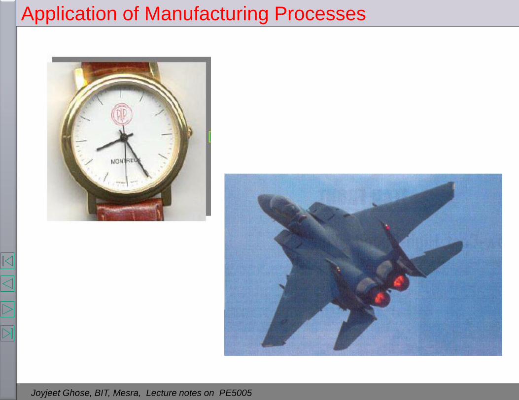
Application of Manufacturing Processes

Joyjeet Ghose, BIT, Mesra, Lecture notes on PE5005
Application of Manufacturing Processes

Joyjeet Ghose, BIT, Mesra, Lecture notes on PE5005
Application of Manufacturing Processes

Joyjeet Ghose, BIT, Mesra, Lecture notes on PE5005
Application of Manufacturing Processes

Joyjeet Ghose, BIT, Mesra, Lecture notes on PE5005
Application of Manufacturing Processes

Joyjeet Ghose, BIT, Mesra, Lecture notes on PE5005
Application of Manufacturing Processes (Gears)

Joyjeet Ghose, BIT, Mesra, Lecture notes on PE5005
Diagrammatic Representation of Material Removal Operations

Joyjeet Ghose, BIT, Mesra, Lecture notes on PE5005
Examples of cutting processes
Source: “ Manufacturing Processes for Engineering Materials”, 4th edition, Kalpakjian, Schmid,
Prentice Hall 2003

Joyjeet Ghose, BIT, Mesra, Lecture notes on PE5005
An Introductory video on Manufacturing Processes

Joyjeet Ghose, BIT, Mesra, Lecture notes on PE5005
Material removal is essentially done on machine tools, which
may be Lathe, Milling, Drilling, Shaping, Planing, Broaching and
Grinding machines.
The functions of machine tools are:
• holding the workpiece
• holding the tool
• moving the tool or the work piece or both relative to each
other,
• supply energy required to cause metal cutting.
Every machine tool has a primary cutting tool for metal removal.
Machine tools are kind of machines on which metal cutting or
metal forming processes are carried out.
Machine Tools

Joyjeet Ghose, BIT, Mesra, Lecture notes on PE5005
Machining Parameters

Joyjeet Ghose, BIT, Mesra, Lecture notes on PE5005
Cutting Parameter Relationships

Joyjeet Ghose, BIT, Mesra, Lecture notes on PE5005
Cutting Parameters
Cutting Speed: Cutting speed is the distance traveled by the work
surface in unit time with reference to the cutting edge of the tool.
The cutting speed, v is simply referred to as speed and usually
expressed in m/min.
Feed: The feed is the distance advanced by the tool into or along the
workpiece each time the tool point passes a certain position in its
travel over the surface.
In case of turning, feed is the distance that the tool advances in one
revolution of the workpiece.
Feed f is usually expressed in mm/rev. Sometimes it is also expressed
in mm/min and is called feed rate.
Depth of cut : It is the distance through which the cutting tool is
plunged into the workpiece surface.
Thus it is the distance measured perpendicularly between the
machined surface and the unmachined (uncut) surface or the
previously machined surface of the workpiece.
The depth of cut d is expressed in mm.

Joyjeet Ghose, BIT, Mesra, Lecture notes on PE5005
Selection of cutting speed and feed
• The selection of cutting speed and feed is based on the following
parameters:
• Workpiece material
• Tool Material
• Tool geometry and dimensions
• Size of chip cross-section
• Types of finish desired
• Rigidity of the machine
• Types of coolant used

Joyjeet Ghose, BIT, Mesra, Lecture notes on PE5005
Selection of cutting speed and feed
Joyjeet Ghose, BIT, Mesra, Lecture notes on PE5005
Cutting tools & its characteristics
Cutting tool is a device, used to remove the unwanted material from given
workpiece. For carrying out the machining process, cutting tool is
fundamental and essential requirement. A cutting tool must have the
following characteristics:
• Hardness: The tool material must be harder than the work piece material.
Higher the hardness, easier it is for the tool to penetrate the work material.
• Hot hardness: Hot Hardness is the ability of the cutting tool must to
maintain its Hardness and strength at elevated temperatures. This property is
more important when the tool is used at higher cutting speeds, for increased
productivity.
• Toughness: Inspite of the tool being tough, it should have enough toughness
to withstand the impact loads that come in the start of the cut to force
fluctuations due to imperfections in the work material. Toughness of cutting
tools is needed so that tools don’t chip or fracture, especially during
interrupted cutting operations like milling.

Joyjeet Ghose, BIT, Mesra, Lecture notes on PE5005
Cutting tools & its characteristics
• Wear Resistance: The tool-chip and chip-work interface are exposed to
severe conditions that adhesive and abrasion wear is very common. Wear
resistance means the attainment of acceptable tool life before tools need to
be replaced.
• Low friction: The coefficient of friction between the tool and chip should
be low. This would lower wear rates and allow better chip flow.
• Thermal characteristics: Since a lot of heat is generated at the cutting
zone, the tool material should have higher thermal conductivity to dissipate
the heat in shortest possible time, otherwise the tool temperature would
become high, reducing its life.

Joyjeet Ghose, BIT, Mesra, Lecture notes on PE5005
Cutting Tool Materials
• Carbon and Medium alloy steels : These are the oldest of the tool materials
dating back hundreds of years. In simple terms it is a high carbon steel (steel
which contains about 0.9 to 1.3% carbon). Inexpensive, easily shaped,
sharpened. No sufficient hardness and wear resistance. Limited to low cutting
speed operation
• High Speed Steel (1900): The major difference between high speed tool steel
and plain high carbon steel is the addition of alloying elements (manganese,
chromium, tungsten, vanadium, molybdenum, cobalt, and niobium) to harden
and strengthen the steel and make it more resistant to heat (hot hardness).
They are of two types: Tungsten HSS (denoted by T), Molybdenum HSS
(denoted by M).
• Cemented Carbides or Sintered Carbides (1926-30): These tools are
produced by powder metallurgy. Carbide tools are basically of three types:
tungsten carbide (WC), tantalum carbide (TaC), and titanium carbide (TiC).
The carbides or combined carbides are mixed with a binder of cobalt. They
are able to retain hardness to a temperature of about 10000C. So they can be
used at high speeds. Carbide tool are available as brazed tip tools (carbide tip
is brazed to steel tool) and inserts (inserts are of various shapes- triangular,
square diamond and round).

Joyjeet Ghose, BIT, Mesra, Lecture notes on PE5005
Typical carbide inserts
FIGURE: (a) Typical carbide
inserts with various shapes
and chip-breaker features.
Round inserts are also
available. The holes in the
inserts are standardized for
interchangeability. Source:
Courtesy of Kyocera
Engineered Ceramics, Inc.,
and Manufacturing
Engineering, Society of
Manufacturing Engineers.
(b) Methods of attaching
inserts to a tool shank by
clamping, (c) with wing
lockpins, and (d) with a
brazed insert on a shank

Joyjeet Ghose, BIT, Mesra, Lecture notes on PE5005
Cutting Tool Materials
FIGURE: Relative edge strength and tendency for chipping and breaking of inserts with various shapes. Strength refers to that of the cutting edge shown by the included angles. Source: Kennametal, Inc.

Joyjeet Ghose, BIT, Mesra, Lecture notes on PE5005
Cutting Tool Materials
Joyjeet Ghose, BIT, Mesra, Lecture notes on PE5005
Cutting Tool Materials

Joyjeet Ghose, BIT, Mesra, Lecture notes on PE5005
Carbides are now so popular that ISO
has developed an application chart.
The chart is divided into three main
areas: ISO - P, M and K.
ISO P: is for the machining of long
chip formation materials.
ISO M: is for the machining of
difficult to machine materials such as
austenitic stainless steel.
ISO K: is for the machining of short
chip formation materials such as
cast iron, hardened steel.
Cutting Tool Materials

Joyjeet Ghose, BIT, Mesra, Lecture notes on PE5005
• Coated cemented carbide (1960): Tool life to about 200 to 300 % or more. A thin, chemically stable, hard refractory coating of TiC, TiN or Al2O3 is used. The bulk of the tool is tough, shock resistant carbide that can withstand high temperatures. Because of its wear resistance, coated tool can be used at still higher speeds.
• Cast cobalt alloys or Stellites (1915): It is a non-ferrous alloy consisting mainly of cobalt, tungsten and chromium (38% to 53% Cobalt, 30% to 33% Chromium, and 4% to 20% Tungsten). Other elements added in varying proportions are molybdenum, manganese, silicon and carbon. It has good shock and wear resistance properties and retains its harness up to 9000C. Stellite tools can operate at speed about 25% higher than that of HSS tools .
• Cemented oxides or Ceramic Cutting Tools (1950s): Non-metallic materials made of pure Aluminum oxide by powder metallurgy. The application ceramic cutting tools are limited because of their extreme brittleness. The transverse rupture strength (TRS) is very low. This means that they will fracture more easily when making heavy interrupted cuts. However, the strength of ceramics under compression is much higher than HSS and carbide tools. It has high hot hardness (up to 1200 degree C), so capable of running at high speeds.
Cutting Tool Materials

Joyjeet Ghose, BIT, Mesra, Lecture notes on PE5005
• Cermets: Cermets are ceramic material in metal binders. TiC, nickel, TiN, and other carbides are used as binders. Cermets have higher hot hardness and oxidation resistance than cemented carbides but less toughness. They are used for finishing operation. The main problem with cermets is that due to thermal shock the inserts crack.
• Diamond: They are of two types - industrial grade natural diamonds, and synthetic polycrystalline diamonds. Because diamonds are pure carbon, they have an affinity for the carbon of ferrous metals. Therefore, they can only be used on non-ferrous metals. Feeds should be very light and high speeds Rigidity in the machine tool and the setup is very critical because of the extreme hardness and brittleness of diamond.
• Cubic Boron Nitride (1962): Cubic boron nitride (CBN) is similar to diamond in its polycrystalline structure and is also bonded to a carbide base. With the exception of titanium, or titanium-alloyed materials, CBN will work effectively as a cutting tool on most common work materials. However, the use of CBN should be reserved for very hard and difficult-to-machine materials.
Cutting Tool Materials

Joyjeet Ghose, BIT, Mesra, Lecture notes on PE5005
Properties of Cutting Tool Materials PROPERTY CARBIDES
HIGH-
SPEED
STEEL
CAST
ALLOYS
WC TiC CERAMICS CUBIC
BORON
NITRIDE
SINGLE-
CRYSTAL
DIAMOND*
Hardness 83-86 HRA 82-84 HRA
46-62 HRC
90-95 HRA
1800-2400
HK
91-93 HRA
1800-3200 HK
91-95 HRA
2000-3000
HK
4000-5000
HK
7000-8000
HK
Compressive strength
MPa
psi x 103
4100-4500
600-650
1500-2300
220-335
4100-5850
600-850
3100-3850
450-560
2750-4500
400-650
6900
1000
6900
1000
Transverse rupture
strength
MPa
psi x 103
2400-4800
350-700
1380-2050
200-300
1050-2600
150-375
1380-1900
200-275
345-950
50-135
700
105
1350
200
Impact strength
J
in.-lb
1.35-8
12-70
0.34-1.25
3-11
0.34-1.35
3-12
0.79-1.24
7-11
< 0.1
< 1
< 0.5
< 5
< 0.2
< 2
Modulus of elasticity
GPa
psi x 105
200
30
-
-
520-690
75-100
310-450
45-65
310-410
45-60
850
125
820-1050
120-150
Density
kg/m3
lb/in3
8600
0.31
8000-8700
0.29-0.31
10,000-
15,000
0.36-0.54
5500-5800
0.2-0.22
4000-4500
0.14-0.16
3500
0.13
3500
0.13
Volume of hard phase
(%)
7-15 10-20 70-90 - 100 95 95
Melting or
decomposition
temperature
°C
°F
1300
2370
-
-
1400
2550
1400
2550
2000
3600
1300
2400
700
1300
Thermal conductivity,
W/mK
30-50 - 42-125 17 29 13 500-2000
Coefficient of thermal
expansion, x
10-6/°C
12 - 4-6.5 7.5-9 6-8.5 4.8 1.5-4.8
* The values for polycrystalline diamond are generally lower, except impact strength, which is higher. Source “ Manufacturing Processes for Engineering Materials”, 4th edition, Kalpakjian, Schmid,
Prentice Hall 2003

Joyjeet Ghose, BIT, Mesra, Lecture notes on PE5005
Cutting tool material and recommended speed range:
FIGURE : The range of applicable cutting speeds and fees for a variety of tool materials.
Source: Valenite, Inc.
Figure from: “ Manufacturing Processes for Engineering Materials”, 4th edition, Kalpakjian,
Schmid, Prentice Hall 2003
Joyjeet Ghose, BIT, Mesra, Lecture notes on PE5005
(a) Hardness of various cutting-tool materials as a function of temperature. (b)
Ranges of properties of various groups of materials.
Cutting tool materials hardness and strength
Source: George Schneider,Jr. CMfgE, Cutting Tool Applications

Joyjeet Ghose, BIT, Mesra, Lecture notes on PE5005
Operating Characteristics of Cutting tool materials

Joyjeet Ghose, BIT, Mesra, Lecture notes on PE5005
Single Point Cutting Tool Geometry

Joyjeet Ghose, BIT, Mesra, Lecture notes on PE5005
Right hand single point cutting tool
FIGURE : (a) Schematic illustration of a right-hand cutting tool. Although these tools have traditionally been produced from solid tool-steel bars, they have been largely replaced by carbide or other inserts of various shapes and sizes, as shown in (b).
Source: “ Manufacturing Processes for Engineering Materials”, 4th edition, Kalpakjian, Schmid,
Prentice Hall 2003

Joyjeet Ghose, BIT, Mesra, Lecture notes on PE5005
Single Point Cutting Tool Geometry
Side rake angle
(αs)
End relief angle (ERA)
Nose Radius (NR)
End cutting edge angle (ECEA)
Side cutting edge angle (SCEA)
Side View
Front View
Top View
Lip angle
Back rake angle (αb)
Side relief angle (SRA)
Geometry of positive rake single point cutting tool

Joyjeet Ghose, BIT, Mesra, Lecture notes on PE5005
Single Point Cutting Tool Geometry
Geometry of negative rake single point cutting tool
Side rake angle (αs)
End relief angle (ERA)
Nose Radius (NR)
End cutting edge angle (ECEA)
Side cutting edge angle (SCEA)
Side View
Front View
Top View
Lip angle
Back rake angle (αb)
Side relief angle (SRA)
Joyjeet Ghose, BIT, Mesra, Lecture notes on PE5005
Significance of Rake and Relief Angles
The Rake Angle Click for video

Joyjeet Ghose, BIT, Mesra, Lecture notes on PE5005
Back rake angle:
•The back rake angle is the angle between the face of the tool and a line
parallel to the base of the shank in a plane parallel to the side cutting edge.
•The back rake angle affects the ability of the tool to shear the work material
and form chip.
Side Rake Angles:
•It is the angle by which the face of the tool is inclined side ways.
The Rake Angle:
The rake angle is always at the topside of the tool.
The side rake angle and the back rake angle combine to form the effective
rake angle. This is also called true rake angle or resultant rake angle of the
tool.
The basic tool geometry is determined by the rake angle of the tool.
Rake angle has two major effects during the metal cutting process.
One major effect of rake angle is its influence on tool strength. A tool with
negative rake will withstand far more loading than a tool with positive rake.
The other major effect of rake angle is its influence on cutting pressure. A
tool with a positive rake angle reduces cutting forces by allowing the chips to
flow more freely across the rake surface.
Cutting tool angles and their significance

Joyjeet Ghose, BIT, Mesra, Lecture notes on PE5005
Cutting tool angles and their significance

Joyjeet Ghose, BIT, Mesra, Lecture notes on PE5005
The rake angle has the following function:
• It allows the chip to flow in convenient direction.
• It reduces the cutting force required to shear the metal and consequently
helps to increase the tool life and reduce the power consumption. It
provides keenness to the cutting edge.
• It improves the surface finish.
Positive Rake:
•Positive rake or increased rake angle reduces compression, the forces, and
the friction, yielding a thinner, less deformed and cooler chip.
•But increased rake angle reduces the strength of the tool section, and heat
conduction capacity.
•Some areas of cutting where positive rake may prove more effective are,
when cutting tough, alloyed materials that tend to work-harden, such as
certain stainless steels, when cutting soft or gummy metals, or when low
rigidity of workpiece, tooling, machine tool, or fixture allows chatter to occur.
•The shearing action and free cutting of positive rake tools will often
eliminate problems in these areas.
Cutting tool angles and their significance

Joyjeet Ghose, BIT, Mesra, Lecture notes on PE5005
Negative Rake:
• To provide greater strength at the cutting edge and better heat
conductivity, zero or negative rake angles are employed on carbide,
ceramic, polycrystalline diamond, and polycrystalline cubic boron
nitride cutting tools.
• These materials tend to be brittle, but their ability to hold their
superior hardness at high temperature results in their selection for
high speed and continuous machining operation.
• Negative rakes increases tool forces but this is necessary to provide
added support to the cutting edge. This is particularly important in
making intermittent cuts and in absorbing the impact during the initial
engagement of the tool and work.
• Negative rakes are recommended on tool which does not possess
good toughness (low transverse rupture strength).
• Thus negative rake (or small rake) causes high compression, tool
force, and friction, resulting in highly deformed, hot chip.
Cutting tool angles and their significance

Joyjeet Ghose, BIT, Mesra, Lecture notes on PE5005
The rake angle for a tool depends on the following factors:
• Type of material being cut: A harder material like cast iron may be
machined by smaller rake angle than that required by soft material
like mid steel or aluminum.
• Type of tool material: Tool material like cemented carbide permits
turning at very high speed. At high speeds rake angle has little
influence on cutting pressure. Under such condition the rake angle
can minimum or even negative rake angle is provided to increase
the tool strength.
• Depth of cut: In rough turning, high depth of cut is given to remove
maximum amount of material. This means that the tool has to
withstand severe cutting pressure. So the rake angle should be
decreased to increase the lip angle that provides the strength to the
cutting edge.
• Rigidity of the tool holder and machine: An improperly supported
tool on old or worn out machine cannot take up high cutting
pressure. So while machining under the above condition, the tool
used should have larger rake angle.

Joyjeet Ghose, BIT, Mesra, Lecture notes on PE5005
• Relief angles are provided to minimize physical interference or rubbing
contact with machined surface and the work piece.
• Relief angles are for the purpose of helping to eliminate tool breakage and
to increase tool life.
• If the relief angle is too large, the cutting tool may chip or break. If the
angle is too small, the tool will rub against the workpiece and generate
excessive heat and this will in turn, cause premature dulling of the cutting
tool.
• Small relief angles are essential when machining hard and strong materials
and they should be increased for the weaker and softer materials.
• A smaller angle should be used for interrupted cuts or heavy feeds, and a
larger angle for semi-finish and finish cuts.
Side relief angle: The Side relief angle prevents the side flank of the tool
from rubbing against the work when longitudinal feed is given. Larger feed
will require greater side relief angle.
End relief angle: The End relief angle prevents the side flank of the tool
from rubbing against the work. A minimum relief angle is given to provide
maximum support to the tool cutting edge by increasing the lip angle. The
front clearance angle should be increased for large diameter works.
Relief Angles
Joyjeet Ghose, BIT, Mesra, Lecture notes on PE5005
Side cutting edge angle:
The following are the advantages of increasing this angle:
• It increases tool life as, for the same depth of cut; the cutting force is
distributed on a wider surface.
• It diminishes the chip thickness for the same amount of feed and
permits greater cutting speed.
• It dissipates heat quickly for having wider cutting edge.
•The side cutting edge angle of the tool has practically no effect on the
value of the cutting force or power consumed for a given depth of cut
and feed.
•Large side cutting edge angles are lightly to cause the tool to chatter.
End cutting edge angle:
The function of end cutting edge angle is to prevent the trailing front
cutting edge of the tool from rubbing against the work. A large end
cutting edge angle unnecessarily weakens the tool.
It varies from 8 to 15 degrees.
Cutting tool angles and their significance

Joyjeet Ghose, BIT, Mesra, Lecture notes on PE5005
Nose radius:
The nose of a tool is slightly rounded in all turning tools.
The function of nose radius is as follows:
• Greater nose radius clears up the feed marks caused by the
previous shearing action and provides better surface finish.
• All finish turning tool have greater nose radius than rough turning
tools.
• It increases the strength of the cutting edge, tends to minimize the
wear taking place in a sharp pointed tool with consequent increase
in tool life.
• Accumulation heat is less than that in a pointed tool which permits
higher cutting speeds.
Cutting tool angles and their significance

Joyjeet Ghose, BIT, Mesra, Lecture notes on PE5005
Tool signature
It is the system of designating the principal angles of a single point cutting
tool.
The signature is the sequence of numbers listing the various angles, in
degrees, and the size of the nose radius.
There are several systems available like American standard system (ASA),
Orthogonal rake system (ORS), Normal rake system (NRS), and
Maximum rake system (MRS).
The system most commonly used is American Standard Association
(ASA), which is:
Bake rake angle, Side rake angle, End relief angle, Side relief angle, End
cutting Edge angle, Side cutting Edge angle and Nose radius.
Joyjeet Ghose, BIT, Mesra, Lecture notes on PE5005
For example a tool may designated in the following sequence:
8-14-6-6-6-15-1 1. Bake rake angle is 8
2. Side rake angle is 14
3. End relief angle is 6
4. Side relief angle is 6
5. End cutting Edge angle is 6
6. Side cutting Edge angle is 15
7. Nose radius is 1 mm
Tool signature
Joyjeet Ghose, BIT, Mesra, Lecture notes on PE5005
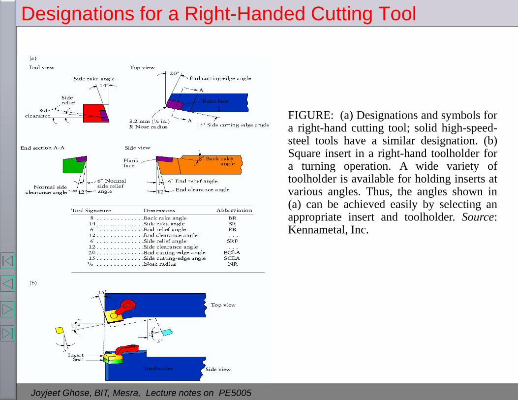
Designations for a Right-Handed Cutting Tool
FIGURE: (a) Designations and symbols for a right-hand cutting tool; solid high-speed-steel tools have a similar designation. (b) Square insert in a right-hand toolholder for a turning operation. A wide variety of toolholder is available for holding inserts at various angles. Thus, the angles shown in (a) can be achieved easily by selecting an appropriate insert and toolholder. Source: Kennametal, Inc.

Joyjeet Ghose, BIT, Mesra, Lecture notes on PE5005
THEORY OF METAL CUTTING
• The process of metal removal, a process in which a wedge-shaped tool engages a workpiece to remove a layer of material in the form of a chip, goes back many years.
• Even with all of the sophisticated equipment and techniques used in today’s modern industry, the basic mechanics of forming a chip remain the same.
• As the cutting tool engages the workpiece, the material directly ahead of the tool is sheared and deformed under tremendous pressure. The deformed material then seeks to relieve its stressed condition by fracturing and flowing into the space above the tool in the form of a chip.
Video showing the wedge-
shape of different tools.
Joyjeet Ghose, BIT, Mesra, Lecture notes on PE5005
Orthogonal and Oblique Cutting
The two basic methods of metal cutting using a single point tool are
the orthogonal (2 D) and oblique (3D). Orthogonal cutting takes place
when the cutting face of the tool is 90 degree to the line of action of the
tool. If the cutting face is inclined at an angle less than 90 degree to
the line of action of the tool, the cutting action is known as oblique.

Joyjeet Ghose, BIT, Mesra, Lecture notes on PE5005
Orthogonal Cutting:
The cutting edge of the tool remains normal to the
direction of tool feed or work feed.
The direction of the chip flow velocity is normal
to the cutting edge of the tool.
Here only two components of forces are acting:
Cutting Force and Thrust Force. So the metal
cutting may be considered as a two dimensional
cutting.
Oblique Cutting:
• The cutting edge of the tool remains inclined at an acute
angle to the direction of tool feed or work feed.
• The direction of the chip flow velocity is at an angle with
the normal to the cutting edge of the tool. The angle is
known as chip flow angle.
• Here three components of forces are acting: Cutting Force,
Radial force and Thrust Force or feed force. So the metal
cutting may be considered as a three dimensional cutting.
The cutting edge being oblique, the shear force acts on a
larger area and thus tool life is increased.
Feed
Tool
Work
Oblique cutting
Feed
Tool
Work
Orthogonal cutting
Orthogonal and Oblique Cutting
Joyjeet Ghose, BIT, Mesra, Lecture notes on PE5005
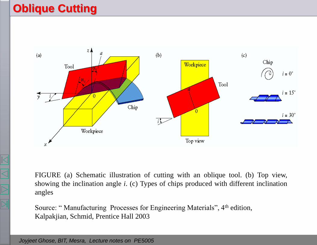
Oblique Cutting
FIGURE (a) Schematic illustration of cutting with an oblique tool. (b) Top view,
showing the inclination angle i. (c) Types of chips produced with different inclination
angles
Source: “ Manufacturing Processes for Engineering Materials”, 4th edition,
Kalpakjian, Schmid, Prentice Hall 2003

Joyjeet Ghose, BIT, Mesra, Lecture notes on PE5005
Mechanics of orthogonal metal cutting
During metal cutting, the metal is severely compressed in the area in
front of the cutting tool.
This causes high temperature shear, and plastic flow if the metal is ductile.
When the stress in the workpiece just ahead of the cutting tool reaches a
value exceeding the ultimate strength of the metal, particles will shear to
form a chip element, which moves up along the face of the work.
The outward or shearing movement of each successive element is arrested
by work hardening and the movement transferred to the next element.
The process is repetitive and a continuous chip is formed.
The plane along which the element shears, is called shear plane.
Click for video

Joyjeet Ghose, BIT, Mesra, Lecture notes on PE5005
Assumptions in orthogonal metal cutting
• No contact at the flank i.e. the tool is perfectly sharp.
• No side flow of chips i.e. width of the chips remains constant.
• Uniform cutting velocity.
• A continuous chip is produced with no built up edge.
• The chip is considered to be held in equilibrium by the action of the two equal and opposite resultant forces R and R/ and assume that the resultant is collinear.

Joyjeet Ghose, BIT, Mesra, Lecture notes on PE5005
Metal cutting Terminologies
Schematic illustration of a two-dimensional cutting
process (also called orthogonal cutting).
Source: “ Manufacturing Processes for Engineering
Materials”, 4th edition, Kalpakjian, Schmid, Prentice
Hall 2003

Joyjeet Ghose, BIT, Mesra, Lecture notes on PE5005
Chip thickness ratios
The outward flow of the metal causes the chip to be thicker after the separation from the parent metal. That is the chip produced is thicker than the depth of cut.
∅
(∅-α)

Joyjeet Ghose, BIT, Mesra, Lecture notes on PE5005
)cos(
sin
s
s
c
o
l
l
t
tr
)cos(
sin
r
Rearranging:
Chip thickness ratio
crr
1
sin1
costan
r
r
)cos(
sin
t
t
c
o
Chip thickness ratio
∅
(∅-α)

Joyjeet Ghose, BIT, Mesra, Lecture notes on PE5005
Velocity Relationship
FIGURE (a) Schematic illustration of the basic mechanism of chip formation in cutting. (b)
Velocity diagram in the cutting zone
Source “ Manufacturing Processes for Engineering Materials”, 4th edition, Kalpakjian, Schmid,
Prentice Hall 2003

Joyjeet Ghose, BIT, Mesra, Lecture notes on PE5005
Vc
Vf
Analytically,
)90sin(sin))(90sin(
sfc vvv
cossin)cos(
sfc vvv
)cos(
sinvv c
f
rvv cf
)-cos(
sinr
)cos(
cosvv c
s
c
cf
cf
t
trvv
wtvwt
0
0c
r As,
v
chip theup flowing material of Volume unit timeper material of Volume
Velocity Relationship

Joyjeet Ghose, BIT, Mesra, Lecture notes on PE5005
The force system in general case of conventional turning process
Cutting forces

Joyjeet Ghose, BIT, Mesra, Lecture notes on PE5005
The largest magnitude is the vertical
force Fc which in turning is larger than
feed force Ff, and Ff is larger than radial
force Fr.
For orthogonal cutting system Fr is made
zero by placing the face of cutting tool at
90 degree to the line of action of the tool.
Cutting forces
Joyjeet Ghose, BIT, Mesra, Lecture notes on PE5005
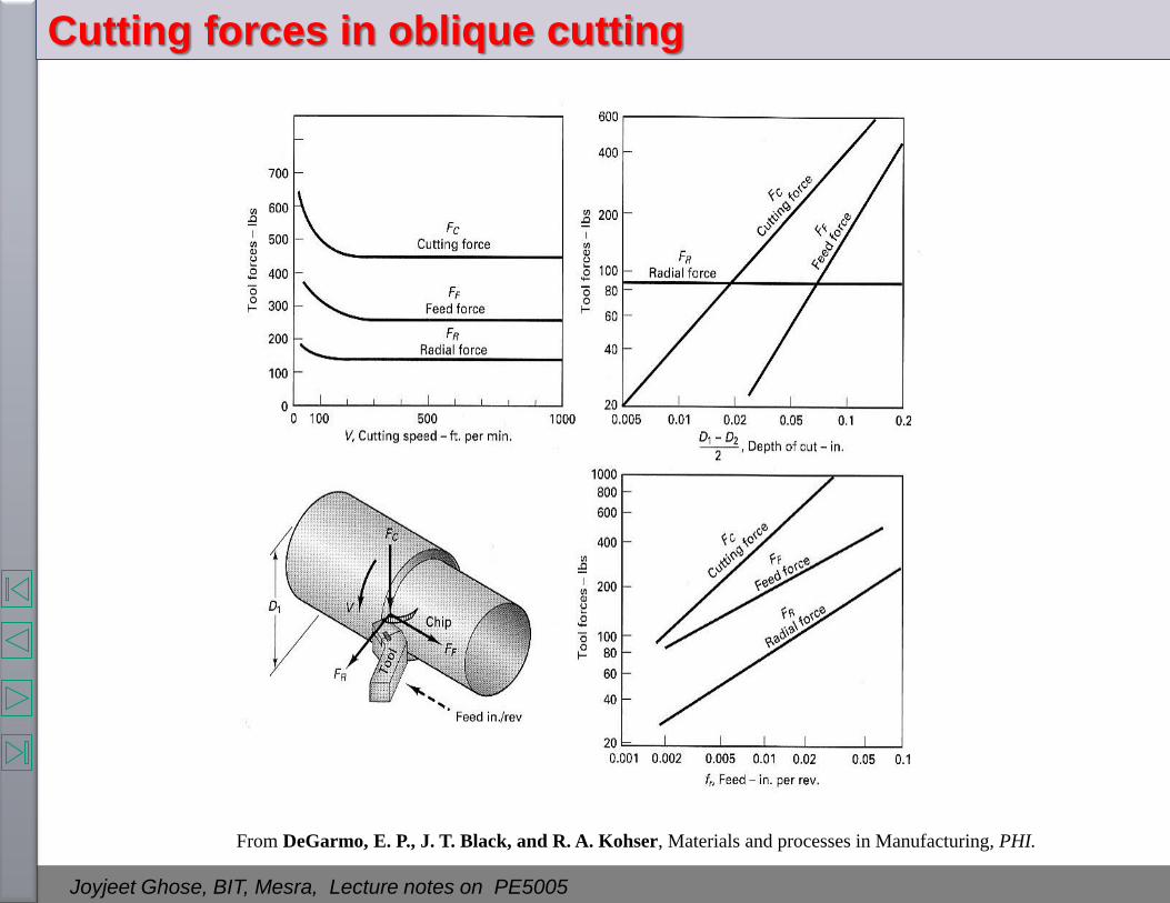
Cutting forces in oblique cutting
From DeGarmo, E. P., J. T. Black, and R. A. Kohser, Materials and processes in Manufacturing, PHI.

Joyjeet Ghose, BIT, Mesra, Lecture notes on PE5005
The forces in orthogonal cutting (turning)

Joyjeet Ghose, BIT, Mesra, Lecture notes on PE5005
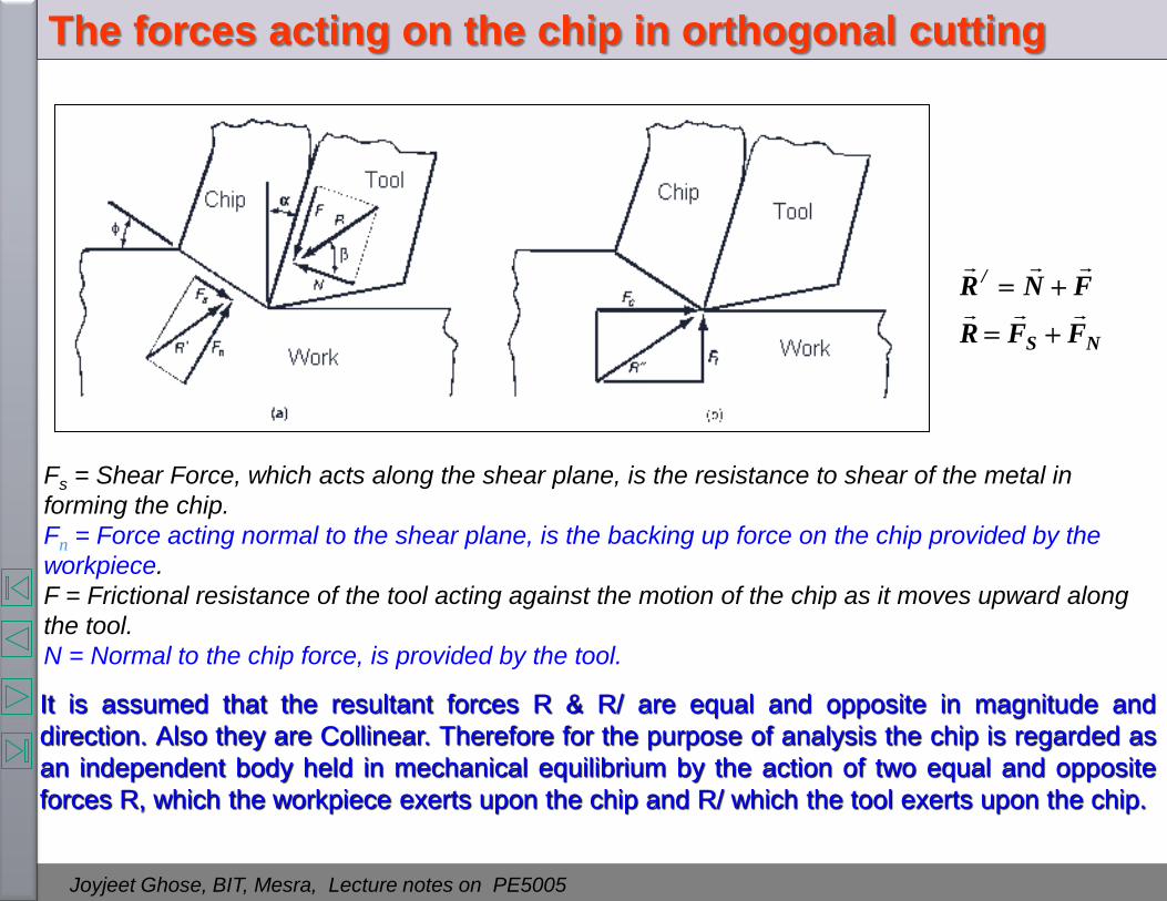
Forces acting on Chip in two-dimensional cutting
Source “ Manufacturing Processes for Engineering Materials”, 4th edition, Kalpakjian, Schmid,
Prentice Hall 2003
Joyjeet Ghose, BIT, Mesra, Lecture notes on PE5005
Fs = Shear Force, which acts along the shear plane, is the resistance to shear of the metal in
forming the chip.
Fn = Force acting normal to the shear plane, is the backing up force on the chip provided by the
workpiece.
F = Frictional resistance of the tool acting against the motion of the chip as it moves upward along
the tool.
N = Normal to the chip force, is provided by the tool.
NS
/
FFR
FNR
It is assumed that the resultant forces R & R/ are equal and opposite in magnitude and
direction. Also they are Collinear. Therefore for the purpose of analysis the chip is regarded as
an independent body held in mechanical equilibrium by the action of two equal and opposite
forces R, which the workpiece exerts upon the chip and R/ which the tool exerts upon the chip.
The forces acting on the chip in orthogonal cutting

Joyjeet Ghose, BIT, Mesra, Lecture notes on PE5005
The following is a circle diagram. Known as Merchant’s circle diagram, which is convenient
to determine the relation between the various forces and angles. In the diagram two force
triangles have been combined and R and R/ together have been replaced by R. the force R
can be resolved into two components Fc and Ft.
Fc and Ft can be determined by force dynamometers.
tc FFR
The rake angle (α) can be measured from the tool, and forces F and N can then be
determined. The shear angle () can be obtained from it’s relation with chip reduction
coefficient. Now Fs & Fn can also be determined.
M. Eugene Merchant
Merchant’s Circle Diagram
∅
Work
Tool Chip
Clearance Angle
Ft
Fc
F
N
Fn
Fs
α
α
β
(β - α)
R

Joyjeet Ghose, BIT, Mesra, Lecture notes on PE5005
Clearance Angle
The procedure to construct a merchants circle diagram
Work
Tool Chip
Ft
Fc
F
N
Fn
Fs
α
α
β
∅
R
Joyjeet Ghose, BIT, Mesra, Lecture notes on PE5005
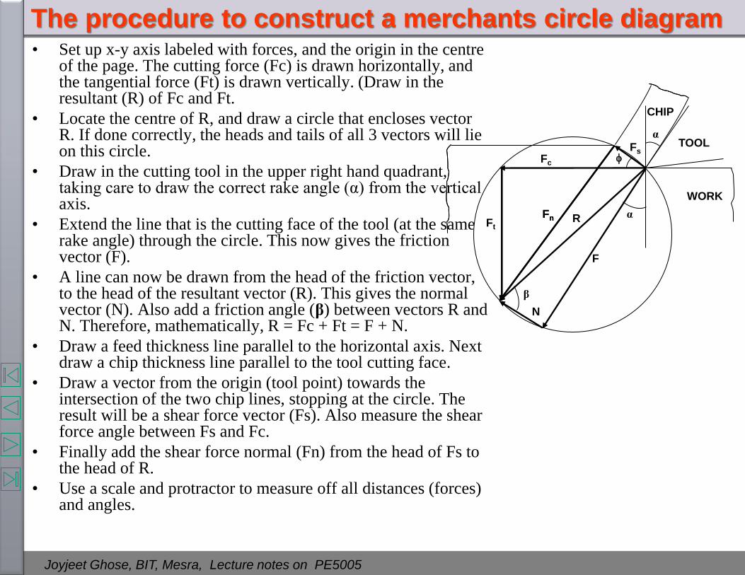
The procedure to construct a merchants circle diagram • Set up x-y axis labeled with forces, and the origin in the centre
of the page. The cutting force (Fc) is drawn horizontally, and the tangential force (Ft) is drawn vertically. (Draw in the resultant (R) of Fc and Ft.
• Locate the centre of R, and draw a circle that encloses vector R. If done correctly, the heads and tails of all 3 vectors will lie on this circle.
• Draw in the cutting tool in the upper right hand quadrant, taking care to draw the correct rake angle (α) from the vertical axis.
• Extend the line that is the cutting face of the tool (at the same rake angle) through the circle. This now gives the friction vector (F).
• A line can now be drawn from the head of the friction vector, to the head of the resultant vector (R). This gives the normal vector (N). Also add a friction angle (β) between vectors R and N. Therefore, mathematically, R = Fc + Ft = F + N.
• Draw a feed thickness line parallel to the horizontal axis. Next draw a chip thickness line parallel to the tool cutting face.
• Draw a vector from the origin (tool point) towards the intersection of the two chip lines, stopping at the circle. The result will be a shear force vector (Fs). Also measure the shear force angle between Fs and Fc.
• Finally add the shear force normal (Fn) from the head of Fs to the head of R.
• Use a scale and protractor to measure off all distances (forces) and angles.
CHIP
WORK
TOOL
α
α
β
F
N
Fc
Ft Fn
Fs
R Fn

Joyjeet Ghose, BIT, Mesra, Lecture notes on PE5005
Merchant’s Circle Diagram
Work
Tool Chip
Clearance Angle
Ft
Fc
F
N
Fn
Fs
α
α
β
∅
(β - α)
R

Joyjeet Ghose, BIT, Mesra, Lecture notes on PE5005
sincos
cossin
tC
tC
FFN
GEODCDODABN
FFF
GBEDGBCGCBOAF
Frictional Force System
angle Friction Where
N
Ftan
friction of tcoefficien The
Relationship of various forces acting on the chip with the horizontal and
vertical cutting force from Merchant circle diagram
Ft
Fc
F
N
α
α
β
(β - α)
R
α α
α
(90-α)
(90-α)
O
A
C
B
G
E
D
∅
Work
Tool Chip
Clearance Angle
Ft
Fc
F
N
Fn
Fs
α
α
β
(β - α)
R

Joyjeet Ghose, BIT, Mesra, Lecture notes on PE5005
Shear Force System
cossin
sincos
tCN
N
tCS
S
FFF
DEBCDEADAEF
FFF
CDOBABOBOAF
Also:
)tan( SN FF
Relationship of various forces acting on the chip with the horizontal and
vertical cutting force from Merchant circle diagram
∅
Work
Tool Chip
Clearance Angle
Ft
Fc
F
N
Fn
Fs
α
α
β
(β - α)
R
∅
Ft
Fc
A
O
Fn
Fs
α
α
(β - α)
R
B
C
D
E
∅
∅
(90-∅)
(90-∅)

Joyjeet Ghose, BIT, Mesra, Lecture notes on PE5005
)tan(
cossin
sincos
sincos
cossin
SN
tCN
tCS
tC
tC
FF
FFF
FFF
FFN
FFF
Relationship of various forces acting on the chip with the horizontal and
vertical cutting force from Merchant circle diagram
∅
Work
Tool Chip
Clearance Angle
Ft
Fc
F
N
Fn
Fs
α
α
β
(β - α)
R

Joyjeet Ghose, BIT, Mesra, Lecture notes on PE5005
The Power consumed/ work done per sec in cutting: CCC vFP
The Power consumed/ work done per sec in shear: sss vFP
The Power consumed/ work done per sec in friction: fF vFP
The total Power required:
velocityfeedFv tc F P
secper feedingin spent work secper cuttingin consumed Work P
motor by the suppliedPower P
c
In comparison to the cutting velocity the feed velocity is very nominal. Similarly Fc is very
small compared to Fc. So the work spent in feeding can be considered negligible.
Therefore, total power required in cutting fsc PPPP
Power required in Metal cutting

Joyjeet Ghose, BIT, Mesra, Lecture notes on PE5005
Specific Energy
Specific Energy, ut ,is defined as the total energy per unit volume of material
removed.
Therefore is simply the cutting force to the projected area of cut.
If uf and us be specific energy for friction and specific energy for shearing ,
then
As the rake angle increases, the frictional specific energy remains more or less
constant, where as the shear specific energy rapidly reduced.
00 wt
F
vwt
vFu C
c
cCt
c
ss
c
ss
c
f
sftvwt
vF
wt
Fr
vwt
vF
vwt
Fvuuu
0000

Joyjeet Ghose, BIT, Mesra, Lecture notes on PE5005
Approximate specific-energy requirements in cutting operations.
MATERIAL SPECIFIC ENERGY*
W-s/mm3 hp-min/in3
Aluminum alloys Cast irons Copper alloys High-temperature alloys Magnesium alloys Nickel alloys Refractory alloys Stainless steels Steels Titanium alloys
0.4-1.1 1.6-5.5 1.4-3.3 3.3-8.5 0.4-0.6 4.9-6.8 3.8-9.6 3.0-5.2 2.7-9.3 3.0-4.1
0.15-0.4 0.6-2.0 0.5-1.2 1.2-3.1
0.15-0.2 1.8-2.5 1.1-3.5 1.1-1.9 1.0-3.4 1.1-1.5
* At drive motor, corrected for 80% efficiency; multiply the energy by 1.25 for dull tools.
Source “ Manufacturing Processes for Engineering Materials”, 4th edition, Kalpakjian, Schmid,
Prentice Hall 2003

Joyjeet Ghose, BIT, Mesra, Lecture notes on PE5005
Ernest and Merchant gave the relation
)(2
1
4
Theory of Ernst and Merchant (1944)
Assumptions of the theory:
• Tool edge is sharp.
• The work material undergoes deformation across a thin shear
plane.
• There is uniform distribution of normal and shear stress on the
shear plane.
• The work material is rigid and perfectly plastic.
• The shear angle ∅ adjusts itself to give minimum work.
• The friction angle β remains constant and is independent of ∅.
• The chip width remains constant.
M. Eugene Merchant

Joyjeet Ghose, BIT, Mesra, Lecture notes on PE5005
0
0
0
sin)cos()sec(
sin
)cos()sec(
sin ,
)cos()sec(
)sec(
)cos(
wt
F
wt
F
wtAwhere
A
F
FF
FR
RF
cs
cs
s
s
ss
cs
c
s
They have assumed that adjusts itself to give minimum work. And for a given set of cutting
condition, to, w and α are all constants. They also assumed that β is independent of .
)(
Theory of Ernst and Merchant (1944)
∅
Work
Tool Chip
Clearance Angle
Ft
Fc
F
N
Fn
Fs
α
α
β
(β - α)
R

Joyjeet Ghose, BIT, Mesra, Lecture notes on PE5005
We can either maximize s or minimize
cF
Therefore in the above equation the term sin)cos(
contains only one variable .
)(2
1
4
2
)2
tan()tan(
cot)tan(
cos)cos(sin)sin(
0
y of value maximumfor
cos)cos(sin)sin(
sin)cos(
d
dy
d
dy
ylet
Experimental verification revealed that the above equation is an
over estimate. Merchant later modified this equation and gave another equation C 2
Where C is the machining constant. Usually 2
C
According to Merchant, C is a property of work material unaffected by cutting conditions, but
grain size and micro structure have an affect on C.
depends upon the work materials.
Theory of Ernst and Merchant (1944)
∅
Work
Tool Chip
Clearance Angle
Ft
Fc
F
N
Fn
Fs
α
α
β
(β - α)
R

Joyjeet Ghose, BIT, Mesra, Lecture notes on PE5005
Merchant attempted an alternative solution assuming that the effect of deformation and friction are
reflected through a change of normal force Fn, acting in a direction perpendicular to the plane of
shear. In turn the normal stress, σn, of the shear plane affects the shear stress, τs, in the direction of
shear.
It was assumed that this is commonly known as Bridgeman’s relation and k is the slope
of τs- σn characteristic n0s k
τs
τo
σn
Slope
k
)tan(1sin)cos(
)cos(get we(4), and (3)equation
)4(sin)cos()sec(
Know,
)3()tan(1
)tan(
get we(2), and (1)equation
)2()tan(
get we,
)tan(F Know We
Relation diagram CircleMerchant theFrom
)1(
0
0
0
0
n
n
0
k
twFFrom
tw
FWe
k
k
From
planesheartheofareathebyDividing
F
k
c
cs
s
ss
s
s
ns
Merchant’s second solution (Modified Merchant’s Theory)
∅
Work
Tool Chip
Ft
Fc
F
N
Fn
Fs
α
α
β
(β - α)
R

Joyjeet Ghose, BIT, Mesra, Lecture notes on PE5005
constant machining is C where
2
cot2
)2cot(
)2sin()2cos(
sin)cos(cos)sin(
sin)sin(cos)cos(
sin)cos(cos)sin(sin)sin(cos)cos(
0y
sin)sin(sin)cos(y
)tan(1sin)cos( yif Therfore
maximum. isr denominato whenminimum, is energy, minimun of principle
1
C
Ck
k
k
k
kk
d
d
k
k
FFrom c
Merchant’s second solution (contd..)

Joyjeet Ghose, BIT, Mesra, Lecture notes on PE5005
sin)cos(
cos
therefore ,)cos(
cos
v
v But
sin
1
v
v
vwt
sinwt
F
vF
vwtA
F
vF
vwt
vF
vwt
vF
strain shear stress shear metalthe ofvolume unitshearing indone Work
Know, We
shearingduring workof loss no gConsiderin
.be strain shearThe
A
F stress normal Mean
A
F stress shear Mean
c
s
c
s
c0
0
s
ss
c0
s
s
ss
c0s
ss
s
c0
ss
s
n
s
s
s
s
Stress and Strain acting on the chip

Joyjeet Ghose, BIT, Mesra, Lecture notes on PE5005
Stress and Strain acting on the chip
Φ
α
Φ
B
D
D/
A
A/
C
E Tool Work
(Φ-α)
(90-Φ)
Shearing of chip
Chip

Joyjeet Ghose, BIT, Mesra, Lecture notes on PE5005
strain shear ofmagnitude The
BE
EA
BE
AE BEAtanABEtan
//
)cos(sin
cos
)cos(sin
)cos(
)cos(sin
)sin(sin)cos(cos
)cos(
)sin(
sin
cos
)tan(cot
)90(90BEA
BE
EA
BE
AE
/
/
Stress and Strain acting on the chip (contd..)
Φ
α
Φ
B
D
D/
A
A/
C
E Tool
Chip
Work
(Φ-α)
(90-Φ)
Shearing of chip

Joyjeet Ghose, BIT, Mesra, Lecture notes on PE5005
Thrust Force vs Rake Angle
FIGURE Thrust force as a function of rake
angle and feed in orthogonal cutting of AISI
1112 cold-rolled steel. Note that at high rake
angles, the thrust force is negative. A
negative thrust force has important
implications in the design of machine tools
and in controlling the stability of the cutting
processes. Source: After S. Kobayashi and E.
G. Thomsen.
Figure from: “ Manufacturing Processes for Engineering Materials”, 4th edition, Kalpakjian, Schmid,
Prentice Hall 2003
Joyjeet Ghose, BIT, Mesra, Lecture notes on PE5005
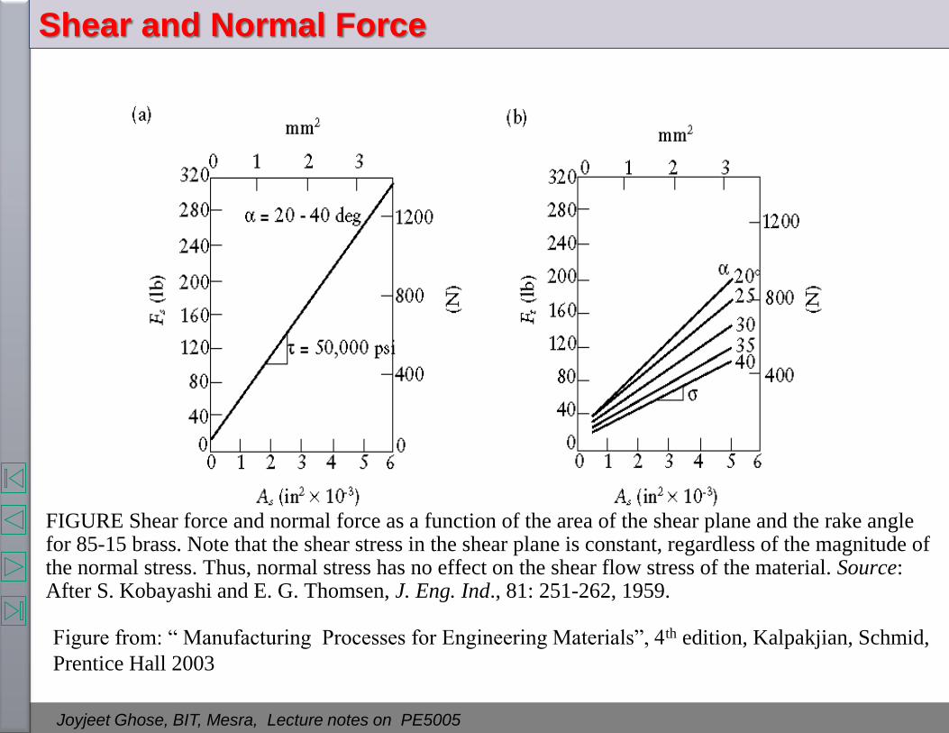
Shear and Normal Force
FIGURE Shear force and normal force as a function of the area of the shear plane and the rake angle for 85-15 brass. Note that the shear stress in the shear plane is constant, regardless of the magnitude of the normal stress. Thus, normal stress has no effect on the shear flow stress of the material. Source: After S. Kobayashi and E. G. Thomsen, J. Eng. Ind., 81: 251-262, 1959.
Figure from: “ Manufacturing Processes for Engineering Materials”, 4th edition, Kalpakjian, Schmid,
Prentice Hall 2003

Joyjeet Ghose, BIT, Mesra, Lecture notes on PE5005
Shear and Normal Force
FIGURE: Schematic illustration of the distribution of normal and shear stresses at the tool-chip
interface (rake face). Note that, whereas the normal stress increases continuously toward the tip of
the tool, the shear stress reaches a maximum and remains at that value (a phenomenon know as
sticking).
Figure from: “ Manufacturing Processes for Engineering Materials”, 4th edition, Kalpakjian, Schmid,
Prentice Hall 2003

Joyjeet Ghose, BIT, Mesra, Lecture notes on PE5005
Temperature Distribution in the Cutting Zone
FIGURE: Typical temperature distribution in
the cutting zone. Note that the maximum
temperature is about halfway up the face of the
tool and that there is a steep temperature
gradient across the thickness of the chip. Some
chips may become red hot, causing safety
hazards to the operator and thus necessitating
the use of safety guards. Source: After G.
Vieregge.
Figure from: “ Manufacturing Processes for Engineering Materials”, 4th edition, Kalpakjian, Schmid,
Prentice Hall 2003

Joyjeet Ghose, BIT, Mesra, Lecture notes on PE5005
Temperature Distribution in Turning
FIGURE : Temperature distribution in turning: (a) flank temperature for tool shape (b) temperature of the tool-chip interface. Note that the rake face temperature is higher than that at the flank surface. Source: After B. T. Chao and K. J. Trigger.
Figure from: “ Manufacturing Processes for Engineering Materials”, 4th edition, Kalpakjian, Schmid,
Prentice Hall 2003

Joyjeet Ghose, BIT, Mesra, Lecture notes on PE5005
Hardness Distribution in the Cutting Zone
FIGURE : (a) Hardness distribution in the cutting zone for 3115 steel. Note that some regions in the built-up edge are as much as three times harder than the bulk metal. (b) Surface finish in turning 5130 steel with a built-up edge. (c) Surface finish on 1018 steel in face milling. Magnifications: 15X. Source: Courtesy of Institute of Advanced Manufacturing Sciences, Inc.
Figure from: “ Manufacturing Processes for Engineering Materials”, 4th edition, Kalpakjian, Schmid,
Prentice Hall 2003

Joyjeet Ghose, BIT, Mesra, Lecture notes on PE5005
References
1. Kalpakjian, Schmid, Manufacturing Processes for Engineering Materials, 4th
edition,, Prentice Hall 2003
2. DeGarmo, E. P., J. T. Black, and R. A. Kohser, Materials and processes in
Manufacturing, PHI.
3. P.N. Rao, Manufacturing Technology – Metal Cutting and Machine Tools, TMH.
4. George Schneider,Jr. CMfgE, Cutting Tool Applications
5. Amstead, B. H., P. F. Ostwald, and M. L. Begeman, Manufacturing Processes,
8th ed., Wiley, New York, 1988.
6. Amitabha Battacharya , Metal Cutting Theory and Practice
7. Shaw, M. C., Metal Cutting Principles, Oxford University Press, Oxford, 1984.
8. Schey, J. A., Introduction to Manufacturing Processes, McGraw-Hill, New York,
1977.
9. Lindberg, R. A., Processes and Materials of Manufacture,
10. William J Patton, Machine tool Operations, Reston publishing company
11. O W Boston, Metal Processing, 2nd edition 1951, John Wiley and Sons
12. B.S.Raghuwanshi, A course in Workshop Technology-Dhanpat Rai & Sons.
13. Hajra Choudhury, Elements of Workshop Technology–Vol.-II, Media Promoters
and Publishers.
14. O P Khanna, Production Technology-(Vol. II)
15. R K Jain, Production Technology
16. HMT, Production Technology, HMT