Manufacturing Capacity Simulation at Primetals Technologies · Manufacturing Capacity Simulation at...
49
1 Manufacturing Capacity Simulation at Primetals Technologies Major Qualifying Project Submitted to the Faculty of WORCESTER POLYTECHNIC INSTITUTE In Partial Fulfillment of the Requirements for the Degree of Bachelor of Science April 23, 2016 Submitted by: Reed Gontarek Bryan Jung Zachary Rahl Emma Raymond Lailah Thompson Sponsor: Primetals Technologies USA LLC Advisors: Walter T. Towner, Jr. Ph.D. Hellen Vassallo, Ph.D.
Transcript of Manufacturing Capacity Simulation at Primetals Technologies · Manufacturing Capacity Simulation at...

1
Manufacturing Capacity Simulation at
Primetals Technologies
Major Qualifying Project Submitted to the Faculty of
WORCESTER POLYTECHNIC INSTITUTE
In Partial Fulfillment of the Requirements for the Degree of Bachelor of Science
April 23, 2016
Submitted by:
Reed Gontarek
Bryan Jung
Zachary Rahl
Emma Raymond
Lailah Thompson
Sponsor:
Primetals Technologies USA LLC
Advisors:
Walter T. Towner, Jr. Ph.D.
Hellen Vassallo, Ph.D.

2
TABLE OF CONTENTS
Abstract ......................................................................................................................................................... 4
Acknowledgements ....................................................................................................................................... 5
1. Introduction ........................................................................................................................................... 6
1.1 Problem Statement .............................................................................................................................. 6
1.2 Project Goals and objectives ............................................................................................................... 7
1.3 Project Deliverables ............................................................................................................................ 7
1.4 Project Scope ...................................................................................................................................... 7
2. Background ........................................................................................................................................... 8
2.1 Primetal’s Technologies ...................................................................................................................... 8
2.1.1 Morgan Construction Company ................................................................................................... 8
2.1.2 Siemens AG/Siemens VAI Metal Technologies ................................................................... 8
2.1.3 Mitsubishi ............................................................................................................................. 9
2.1.4 Primetals ............................................................................................................................. 10
2.2 Roll Housing Assembly & Value Stream Map ........................................................................... 10
2.3 Simulation Programs ................................................................................................................... 12
2.3.1 Other Capacity Planning Programs ..................................................................................... 13
2.4 Axiomatic Design ....................................................................................................................... 14
3. Materials & Methodology ................................................................................................................... 16
3.1 Initial Analysis and Diagnosis .......................................................................................................... 17
3.2 Design Simulation Program .............................................................................................................. 18
3.3 Testing the Simulation Program ....................................................................................................... 18
4. Results ................................................................................................................................................. 20
4.1 Axiomatic Design ............................................................................................................................. 20
4.2 Mathematical Model ......................................................................................................................... 22
4.3 Simulation ......................................................................................................................................... 24
Horizontal Machining Centers 5 & 6 .................................................................................................. 24
Entire Manufacturing System ............................................................................................................. 26
4.4 Manufacturing Process Analysis ....................................................................................................... 26
4.5 Financial Analysis ............................................................................................................................. 28
5. Discussion ........................................................................................................................................... 35
6. Recommendations ............................................................................................................................... 37

3
7. Conclusion .......................................................................................................................................... 39
8. References ........................................................................................................................................... 41
9. Appendix A – Simulation one HMC5 & HMC 6 .............................................................................. 42
Process for HMC5 & HMC6 ..................................................................................................................... 42
Simulation Code for HMC5 and HMC6 ................................................................................................. 42
Partial HMC5 & HMC6 Results for Dispatch List 02-01-16 ................................................................. 42
10. Appendix B – RHA Manufacturing Process ................................................................................... 43
Entire RHA Simulation ........................................................................................................................... 43
Simulation Logic for RHA Manufacturing Process ................................................................................ 44
Results of RHA Simulation .................................................................................................................... 45
11. Appendix C – Mathematical Model ................................................................................................ 46
Original Data ........................................................................................................................................... 46
HMC5: -4+79*BETA(0.545, 1.25) ......................................................................................................... 47
HMC6: -7 + WEIB(12.7, 2.08) ............................................................................................................... 47
HH40: 1+ WEIB(28.8, 1.19) ................................................................................................................... 47
L74R: TRIA(-1, 1.4, 6.99) ...................................................................................................................... 48
A71M: -6 + 21*BETA(5.73, 11.3) ......................................................................................................... 48
WW3P: -2+EXPO(8.74) ......................................................................................................................... 48
HH6S: -7 + 30*BETA(2.64, 1.55) .......................................................................................................... 49

4
ABSTRACT
The objective of this MQP was to provide Primetals Technologies with a better
understanding of their current manufacturing floor capacity. The team created a capacity
simulation focusing on horizontal machining centers, and the Roll Housing manufacturing
process. The methods used were company data, axiomatic design, direct observations, and
process simulation. The team approached the problem by a hierarchical problem solving method,
by the development of a process simulation in Rockwell’s ARENA® program. The team
concluded that Primetals could know how their production system would respond under different
changes in demand with a higher degree of accuracy. The team’s financial analysis shed light on
the cost to the company of making real time changes to the production schedule.

5
ACKNOWLEDGEMENTS
We would like to thank the entire team at Primetals Technologies for their dedication and
support during the completion of our project. We specifically would like to acknowledge the
following people:
Alberto Ortega- Lean Manufacturing Manager
Bonnie Specht- Production Planner
Walter Towner- Project Advisor
Helen Vassallo- Project Advisor
Renata Konrad- Assistant Professor (aided with developing simulation program)

6
1. INTRODUCTION
Primetals Technologies is a manufacturer of steel rolling mills that was formed as a result of a
joint venture between Mitsubishi and Siemens in 2015 (Specht, 2016). Primetals processes
include steel making, casting, rolling, milling, and turning of metals. The Primetals
manufacturing plant located in Worcester, Massachusetts, formerly known as Morgan
Construction, is world renowned for its manufacturing of steel machined products, which had
existed for 130 years prior. Products that the Worcester plant specializes in includes the Morgan
Vee No-Twist rolling mill.
1.1 PROBLEM STATEMENT Primetals in Worcester operates as a job shop, fulfilling customized customer orders for
steel rolling mills, along with their secondary business of manufacturing replacement parts. Due
to the nature of customized orders, Primetals does not currently have an easy, efficient and
accurate system of forecasting the costs and time to fill each order. This transcends into capacity
and production planning issues that can result in long lead times and misinformed decisions,
which has led to difficulty in the face of increasing competition. The use of a simulation tool will
enable management to make better decisions such as effectively allocating resources and
tracking progress on delivery commitments. Therefore, in their efforts in continuous process
improvement, Primetals has sponsored this MQP with Worcester Polytechnic Institute. During
the previous academic year, there was an MQP team at Primetals that was devoted to reducing
the lead time of the production of the Roll Housing Assembly. For this year’s MQP, the
proposed project charter stated a goal of developing a simple computer model that reflects the
changes necessary in the manufacturing department to respond to changes in customer demand.

7
1.2 PROJECT GOALS AND OBJECTIVES
The overall goal of this project was to develop a simple simulation modeling program
that will show how to adjust the factory resources for optimal use of labor and production assets
based on incoming changes in customer demand. The scope of the simulation encompasses
solely the Roll Housing Assembly (RHA) Department and Horizontal Machining Centers
(HMC) that make them in the manufacturing department. The team used axiomatic design to
define the problem and develop an approach to the model. By using axiomatic design, the team
was able to identify the customer needs, functional requirements, and design parameters of the
model. Then the team observed data from the manufacturing floor and personal interviews. Next
the team developed the simulation model using Arena. Once the model was established, the team
performed an economic analysis of the current manufacturing process to evaluate the financial
impact of the simulation model. The objectives included the ability to calculate standard
allowable minutes (SAM) for the RHA and the HMCs along with determining global and local
efficiencies.
1.3 PROJECT DELIVERABLES The project deliverable was a computer model that simulates the impact of customer demand on
the defined production processes.
1.4 PROJECT SCOPE The team’s simulation will be primarily focused on the Roll Housing Machining Assembly and
the horizontal machining centers that produce them.

8
2. BACKGROUND
In order to fully find and develop a solution, the team conducted research at the project sponsor,
Primetals, the production lines within scope, simulation programs, and axiomatic design, which
are described in the following sections.
2.1 PRIMETAL’S TECHNOLOGIES
2.1.1 Morgan Construction Company
The location for this project took place at the Primetals Technologies facility in
Worcester, Massachusetts. Formerly known as Morgan Construction Company, this facility
specializes in the production of high-quality rolling mills which includes rod, section, and wire
rolling mills (Lean Process Improvement of Roll House Manufacturing, 2015). This project
specifically focused on the roll housing assembly and the horizontal machining centers. Morgan
Construction Company was founded in 1891 by WPI founder Charles Hill Morgan. For over a
century, Morgan Construction Company was a global leader in the manufacturing of high-
performing rolling mills. In 2008, Siemens/VAI acquired Morgan Construction Company,
increasing its share in the metal technologies industry (Siemens VAI, 2008).
2.1.2 Siemens AG/Siemens VAI Metal Technologies
Siemens AG is a German international conglomerate that offers a wide range of products
and services for almost every industry. Founded in Berlin, Germany in 1847 by Werner von
Siemens, Siemens is a global powerhouse in electrical engineering and electronics. The company
has 343,000 employees working across the globe to develop and manufacture products, design
and install complex systems and projects, and tailor a wide range of services for individual
requirements (Siemens AG, 2014). In the fiscal year of 2014, Siemens generated £78.5 billion
pounds in revenue with a net income of £5.5 billion pounds (Siemens AG, 2014). Siemens has

9
various business sectors that include power and gas, wind power and renewables, power
generation services, energy management, building technologies, mobility, digital factory, process
industries and drives, financial services, and healthcare.
Siemens/VAI Metal Technologies (SMT) was a vertically integrated business unit that
led the way in the global metallurgical industry. The Siemens/VAI partnership was started in
1995 and is currently headquartered in Linz, Austria. Siemens/VAI’s customer base, roughly
around 500 customers, accounts for 70 percent of global steel production (Siemens VAI, 2015).
Services previously offered had included plant construction, modernization of existing plants,
and installation of integrated state-of-the-art production systems. Siemens/VAI Metal
Technologies became defunct in 2015 after signing a deal to enter a joint venture with Mitsubishi
Heavy Industries to provide plants, products and services for the metals industry. The joint
venture is 51% owned by Mitsubishi, while the remaining stake is held by Siemens.
2.1.3 Mitsubishi
Mitsubishi was founded in 1870 by Yataro Iwasaki when he set up his own shipping
company with three steamships chartered from his clan, the Tosa clan. The company continued
to grow further when Yataro’s son, Hisaya, assumed the presidency in 1893. Hisaya restructured
the company to support increasingly diverse business operations. He set up divisions for
banking, real estate, marketing, and administration, as well as for the original mining and
shipbuilding businesses (Mitsubishi, 2015). The Mitsubishi Group is a National Multinational
Enterprise with no parent company. It is the result of 40 individual companies that own
substantial shares of the other 40 companies. Instead of a parent company exercising control of
the subsidiaries, the three most important companies oversee the operations of the company as a

10
whole. These sister companies are Mitsubishi Bank, the Mitsubishi Corporation, and Mitsubishi
Heavy Industries.
2.1.4 Primetals
Primetals is a firm based in London, UK formed as a result of a joint venture between
Siemens VAI Metal Technologies and Mitsubishi Heavy Industries. The company specializes in
engineering and plant construction for clients in the metals industry, both ferrous and nonferrous
metals (Primetals, 2015). The combined company has a total of 9,000 employees worldwide in
countries including China, India, The United States, and the United Kingdom. Primetals
specializes in machining processes including ironmaking, steelmaking, continuous casting, hot
rolling long, hot rolling flat, cold rolling, nonferrous rolling, processing, endless casting &
rolling, and mini mills.
2.2 ROLL HOUSING ASSEMBLY & VALUE STREAM MAP
The Roll Housing is a crucial part to the Morgan Vee No-Twist mill. The Roll Housing is
responsible for producing the proper size of the manufactured steel. The steel passes through a
carbide roll connected to the pinion shafts which are all supported by the Roll Housing. The
housing itself consists of a box and a front plate. There are different sizes of Roll Housings in
order to make the Morgan Vee No-Twist mill more customizable for the customer. Therefore,
there are different size roll houses to allow for the company to produce variable size steel. Due to
the importance of this specific part, the Roll Housing was the focus of the 2014 WPI MQP team
at Siemen’s VAI (which is now Primetals Technologies.) The goal of their project was to
increase productivity of the Roll Housing assembly. Therefore, they created a process map for
the Roll Housing assembly, including all possible routings (Brofford et al, 2015).
11
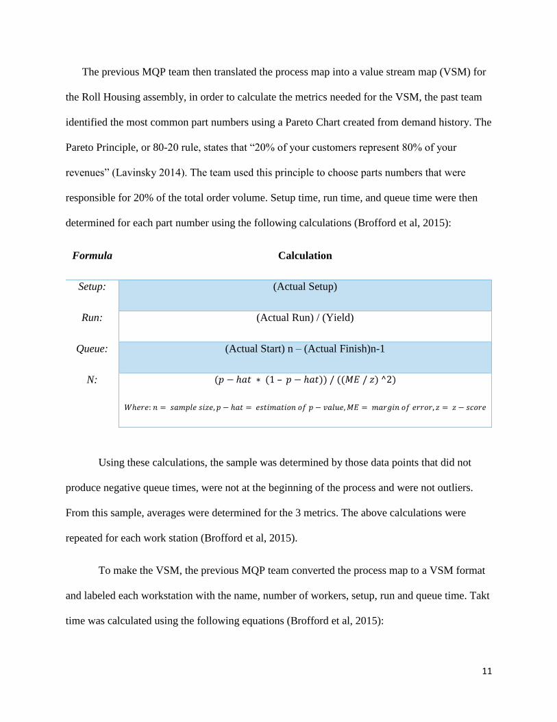
The previous MQP team then translated the process map into a value stream map (VSM) for
the Roll Housing assembly, in order to calculate the metrics needed for the VSM, the past team
identified the most common part numbers using a Pareto Chart created from demand history. The
Pareto Principle, or 80-20 rule, states that “20% of your customers represent 80% of your
revenues” (Lavinsky 2014). The team used this principle to choose parts numbers that were
responsible for 20% of the total order volume. Setup time, run time, and queue time were then
determined for each part number using the following calculations (Brofford et al, 2015):
Formula Calculation
Setup: (Actual Setup)
Run: (Actual Run) / (Yield)
Queue: (Actual Start) n – (Actual Finish)n-1
N: (𝑝 − ℎ𝑎𝑡 ∗ (1 – 𝑝 − ℎ𝑎𝑡)) / ((𝑀𝐸 / 𝑧) ^2)
𝑊ℎ𝑒𝑟𝑒: 𝑛 = 𝑠𝑎𝑚𝑝𝑙𝑒 𝑠𝑖𝑧𝑒, 𝑝 − ℎ𝑎𝑡 = 𝑒𝑠𝑡𝑖𝑚𝑎𝑡𝑖𝑜𝑛 𝑜𝑓 𝑝 − 𝑣𝑎𝑙𝑢𝑒, 𝑀𝐸 = 𝑚𝑎𝑟𝑔𝑖𝑛 𝑜𝑓 𝑒𝑟𝑟𝑜𝑟, 𝑧 = 𝑧 − 𝑠𝑐𝑜𝑟𝑒
Using these calculations, the sample was determined by those data points that did not
produce negative queue times, were not at the beginning of the process and were not outliers.
From this sample, averages were determined for the 3 metrics. The above calculations were
repeated for each work station (Brofford et al, 2015).
To make the VSM, the previous MQP team converted the process map to a VSM format
and labeled each workstation with the name, number of workers, setup, run and queue time. Takt
time was calculated using the following equations (Brofford et al, 2015):

12
(𝑇𝑜𝑡𝑎𝑙 𝐻𝑜𝑢𝑟𝑠) / (# 𝑃𝑖𝑒𝑐𝑒𝑠) = 𝑇𝑎𝑘𝑡 𝑇𝑖𝑚𝑒
(𝑊𝑜𝑟𝑘𝑖𝑛𝑔 𝐷𝑎𝑦𝑠 𝑃𝑒𝑟 𝑌𝑒𝑎𝑟) ∗ ( 𝐻𝑜𝑢𝑟𝑠 𝑃𝑒𝑟 𝑆ℎ𝑖𝑓𝑡) = 𝑇𝑜𝑡𝑎𝑙 𝐻𝑜𝑢𝑟𝑠
Lastly, material and information flow lines were added to the VSM. Material flow lines were
determined by examining material movement. Information flow lines were determined by
communications influencing forecasting, planning, and order fulfillment (Brofford et al, 2015).
2.3 SIMULATION PROGRAMS
Simulation is the act or process of modeling real life activities without physically doing
such acts. (Konrad, 2016) Simulation software models these processes through a set of
mathematical equations. Once a process or operation can be reduced to a set of mathematical
equations/ formulas, it can be simulated on a software. This enables one to view the type of
changes or effects on a system that occur by changing some inputs. This can be used to make and
evaluate decisions before performing them.
A model is a set of assumptions and approximations about how a system works.
Essentially a model mimics reality. There are several types of models. The simple models are
traditional math analysis such as queuing theory, linear programming and differential equations.
Simulations are the more complex models. Models give the ability to manipulate processes
virtually and perform the following: compress and expand time, control sources of validation,
stop & review, restore system state, facilitate replication and control level of detail. A simulation
analysis is conducted by modeling, simulating and then analyzing the systems. Simulation
models can be characterized as deterministic or stochastic, and static or dynamic. Computers can
be used to simulate via spreadsheets, typical for static models, simulation languages and lastly
high-level simulators. (Konrad, 2016)

13
There are several steps for a simulation study: (Konrad, 2016)
1. Understanding the system
2. Identify the goals
3. Collect & analyze data
4. Formulate model representation
5. Translate into modeling software
6. Verify program
7. Validate model
8. Design experiment
9. Make runs
10. Generate insight
2.3.1 Other Capacity Planning Programs
Primetals currently uses a commonly available enterprise resources planning system called
SAP for record accounting, order tracking, routings, and build of material workbooks. The
software also has the ability to account for change over time per batched items while including
setup times in hours. This software lacks specific inventory optimization options and other
capabilities that the company would like. Primetals would like to have the ability to reduce
queuing time within the factory, then implement the changes in real time.
The Production Scheduling Department is tasked with creating work dispatch lists (digital
to-do lists) for assigned work. Such lists will contain data that allocate tooling, labor, machines
and other resources. A few examples of production scheduling software include: TACTIC©,
EnterpriseIQ Scheduling©, and Optessa©.

14
TACTIC has been developed by Waterloo Manufacturing to create dispatch lists based on
live data from active machines and available labor. This software allows one to build detailed
short term schedules, create long term plans, produce schedules and plans that consider capacity
constraints from the inputted data, and evaluate what if analysis. Everything put into the system
can be used to generate simulation alternatives to achieve customer and business needs.
Optessa is a production scheduling Software Company that has been around for 40 years.
Its product is used by such companies as Ford and General Motors for production scheduling and
planning: “These companies evaluated Optessa technology against both in-house developed
legacy systems and solutions offered by other vendors in the planning and scheduling space”
(Optessa, 2015). The software offers complete models that incorporate product data, BOMs, and
routings, for labor and plant constraints the in turn reflect customer demand. Optessa’s stochastic
approach allows them to deliver solutions in real time.
Lastly EnterpriseIQ is a detailed planning software company. The program allows for "what
if" analysis to determine availability of raw materials and parts on hand. It can integrate with
sales modules to deliver more accurate forecasting. Additionally, this program can track active
and projected work orders and create a production plan from the data. It tracks materials and
assemblies by “manag[ing] all resources necessary to meet manufacturing demand, while
maintaining lean inventory levels. It includes items manufactured internally and through third
party vendors, as well as sub-assemblies” (IQMS, 2015).
2.4 AXIOMATIC DESIGN
Axiomatic Design is a systems design methodology originally discovered by Dr. Suh Nam Pyo
at the Massachusetts Institute of Technology in the late 1970's (Towner, 2013) and then

15
subsequently published during the 1990’s (Suh, 1990). This system entails using matrix methods
to systematically analyze the transformation of customer needs into functional requirements,
design parameters, and process variables. This method is based upon its use of design principles,
or axioms, to govern the analysis and decision making process in developing high quality
product or system designs. The two axioms which are used in this process are the independence
axiom and the information axiom.
The independence axiom requires the independence of the functional requirements (FRs)
that fulfill the customer needs. The information axiom is required to minimize the information
content of the design in order to make it as simple and clear as possible. Between these two
axioms, the problem is decomposed in a way that is mutually exclusive and completely
exhaustive (Towner, 2013). For each FR created, there should be a correlating design parameter
that may or may not affect multiple FRs. This process was useful to the team as the
manufacturing system that was attempted to be replicated was complex with many machines
within routings. By using this process, the team was able to make objective decisions about the
project throughout the duration.
Some benefits from using this methodology can include but, are not limited to, providing
metrics for progress and quality, removing non-productive iterations, reduced complexity,
reduced costs, reduced design times, and providing a clear visual when deciding between
different solutions to a complex problem (Towner, 2013). The use of Axiomatic Design in this
project is a natural fit as this project requires the team to break down the process by which the
capacity is affected by customer demand. By decomposing the larger issue into smaller more
specific issues, it allows the team to better diagnose different effects that may result from
solutions to each functional requirement on others. This process began when the team completed

16
a decomposition of the project in order to better understand the essential components that would
be needed to be addressed.
3. MATERIALS & METHODOLOGY
Figure 1 below illustrates the methodology and materials used to design the simulation program
that models the relationship between customer demands and production scheduling. Each of the
three phases consumed about 7 weeks. This entire project was completed within three academic
terms at WPI.
Figure 1: Materials and Methodology (Authors, 2015)

17
3.1 INITIAL ANALYSIS AND DIAGNOSIS The team started working on this project with some knowledge that had been transferred to
the current team from the previous MQP team. However, the current team decided it would be
best to gather some objective data and conduct independent observations directly as a team, in
addition to previously received data. The team visited the Primetals facility in Worcester to
speak with those who would be heavily involved with this project as well as those who may have
information that could be beneficial to the team. The team began this process by taking a tour of
the facility so that the team could get a general view of what operations were done in the facility
and which processes the team would be focusing on with this project.
The first course of action taken in this process was meeting with the sponsor to get a
general idea of what the project scope would be. By doing so, the team was able to gain an
understanding of what kind of data would need to be collected and what kind of metrics should
be used in analyzing the results. After this meeting, the sponsor provided the team with data from
their system that included cycle times for the machines, queue times, as well as other important
data that would be analyzed. While examining the data, the team worked to identify the problems
that were adversely affecting the production system. After analyzing the provided data, it was
determined that the first goal would be to identify bottlenecks within the system that were
interrupting the machining time and causing excessive lead times, as well as impacting the sales
schedule. After attempting to identify these bottlenecks, the team decided to look at other factors
that could affect the system attempting to take into account as many variables and different
processes that could have an impact. By doing this, there were some external factors that were
identified as possible problems. Ultimately, by analyzing the data and the current systems in
place within the company, the team was able to compile a list of areas that had room for
improvement and could possibly be addressed directly by this project's deliverable.

18
3.2 DESIGN SIMULATION PROGRAM The team developed a simulation of a part of the manufacturing system using Arena®, by
Rockwell Automation. The team chose this program because of its ease of accessibility and
ability to animate a model to show how a part moves through the factory. The program also
integrates the use live data via Excel sheets. In addition, Arena® produces many types of output
data in the forms of: queue times, number of parts produced, and process times that will be
helpful for production planning at Primetals. The team used part routings and other data provided
by the sponsor to create the simulation. These routings provided the process times, and
distribution of arrival times. The team first created the simulation a simple process within the
factory, in order to ensure that just the model would be effective for the company. In order to
create this simple model, the routing of one part was used. After the model was approved by the
sponsor, the team created the full simulation using the routings for all the parts.
3.3 TESTING THE SIMULATION PROGRAM Two simulation programs were designed; the first focused on specific machines such as
the HMC 5 and the HMC6, and the second of the entire roll housing machining assembly. These
models were to simulate a month’s worth of work at Primetals for each machine. For the HMC5,
the simulation program was set to run 20 hours per day, 30 days per month and was replicated 7
times within the program to provide a good average of the production times. The program
produced results similar to that of Primetals actual production by using mathematical
distributions along with the assigned routed hours per part and the specified work time exclusive
of operator's schedule. The simulation is based on the time the machines are running, the work
available/provided by the dispatch list and the times the factory is open. The results show how
many jobs can be completed, excluding transfer or transportation time, and the use of operators
available. Based on the project charter, and visual approval by the production scheduler, the

19
results of the simulation, including machine utilization, wait time, Work in Progress (WIP) and
process time are as accurate as then can be.

20
4. RESULTS
4.1 AXIOMATIC DESIGN Axiomatic design was used to accurately define the problem to set the stage for the entire
project. This enabled the team to dissect the problem and develop a plan on how to approach the
solution. Once the team fully understood the problem statements and project scope from the
sponsor, the team was able to break down the requirements of the solution for good
communication between everybody. The team translated the functional requirements and design
parameters of the simulation program with the use of Acclaro® DFSS (Axiomatic Design
Solutions, 2016). Working through the axiomatic design decomposition provided clarity and
transparency between both the expectations of the sponsor and the team, ensuring that
throughout the entire process our work aligned with the sponsor’s goals. Creating the coupling
matrix showed the interactions between the FR's and DP's, and ensured that all requirements of
the simulation program were met before submitting the final design to the sponsor. In addition,
axiomatic design directed the process in the sense that it provided clarity on what information the
team needed to know in order to be successful. Figure 2 shows the functional requirements the
team developed using Axiomatic Design.
Figure 2: Functional Requirements of Axiomatic Design (Authors, 2015)

21
The original problem statement called for the team to create a simulation program that
modeled the impact of production loading on the RHA and HMC's hence the top level functional
requirement. Since the team aimed at building a simulation thus the design parameter calls for a
system to perform the main functional requirement. Then team decomposed the main problem
into three upper level FR's. The first FR is to show the current load of manufacturing system.
The simulation needs to be able to mimic the current process and operations undergoing at
Primetals and needs to be as accurate as possible. In order to fulfill this requirement sub FR's
were created such as the ability to input current load information into the simulation.
Subsequently for each functional requirement, the team needed a system that enables the
requirements to occur which in turn is a design parameter. Hence, Arena® (Rockwell, 2016) was
the software the team decided to use because it had the capacity to fulfill all of the design
parameters. Arena® (Rockwell, 2016) enabled users to input current load information into the
simulation and show the results of such inputs in terms of but not limited to efficiency, process
time, queue time, machine utilization, non-value added and value added time. These were most
of the sub-level functional requirements. Once the functional requirements and design
parameters were defined, the team analyzed the coupling matrix that resulted as seen in Figure
3.

22
Figure 3: Coupling Matrix of the Axiomatic Design (Authors, 2015)
As can be seen above in the coupling matrix, X’s and O’s which indicate relationships
between the FR's and DP's. An X indicates a direct relationship between the FR and DP which
means that one directly impacts the other while an O indicates an indirect relationship between
the two meanings that while they are related, one does not directly affect the other. The team
used Axiomatic Design for its versatile facilitation of problem diagnosis. Every step taken to
break down the functional requirements of the problem, led to the discovery of additional require
steps. Within FR 2, there are 2 subsets: FR 2.1 and 2.1, however in FR3 there are 3 subsets
FR3.1, 3.2 and 3.3. Unlike FR2, FR 3 had more meat to it, this is also seen in FR 3.3 which was
later broken into 3.3.1 and 3.3.1. The change in FRs show the needed level of detail to properly
define the parent FR per section.
4.2 MATHEMATICAL MODEL
In developing the simulation model, the team needed to create a mathematical logic basis
for values assigned to entities for processing time inside the model while it was running. The
team started by looking at current dispatch lists, a list of actual hours against routed hours dating
back to 2013 and a project file created by one of the planners at Primetals. In doing this, the team

23
calculated the differences in actual times against routed hours for each individual machine. The
team encountered some difficulties in comparing hours between the project file and the dispatch
list due to numerous similarities in the descriptions of the order. By combining the operation
number and the order number into a new column labeled "Unique Identifiers", the team was able
to accurately compare processing time for every operation on every part. All differences in
processing times were compiled into lists sorted by machine then uploaded as a dataset to the
input analyzer application of Arena® (Rockwell, 2016). By creating these distributions, the team
was able to incorporate some heuristics currently used by the planners in their project files that
were unavailable from the original files. Some of these heuristics that are not taken into account
for the current calculated routed hours in the current SAP system include: extended set up times,
quality checks for specific orders, programming errors, and the knowledge of operating hours for
certain material types as well as certain types of orders from scheduling coordinators. The team
then used each of these distributions by adding them to the original routed hours the model
picked from the dispatch lists that were being used. By doing this, the simulation was able to
alter machining times to create a much more accurate simulation of the machining process within
the plant. The final results, in terms of hours, of this analysis for each machine are the following
distributions shown in Figure 4:
Machining Center Distribution
HMC5 -4 + 79 * BETA(0.545, 1.25)
HMC6 -7 + WEIB(12.7, 2.08)
HH40 1 + WEIB(28.8, 1.19)
L74R TRIA(-1, 1.4, 6.99)
A71M -6 + 21 * BETA(5.73, 11.3)
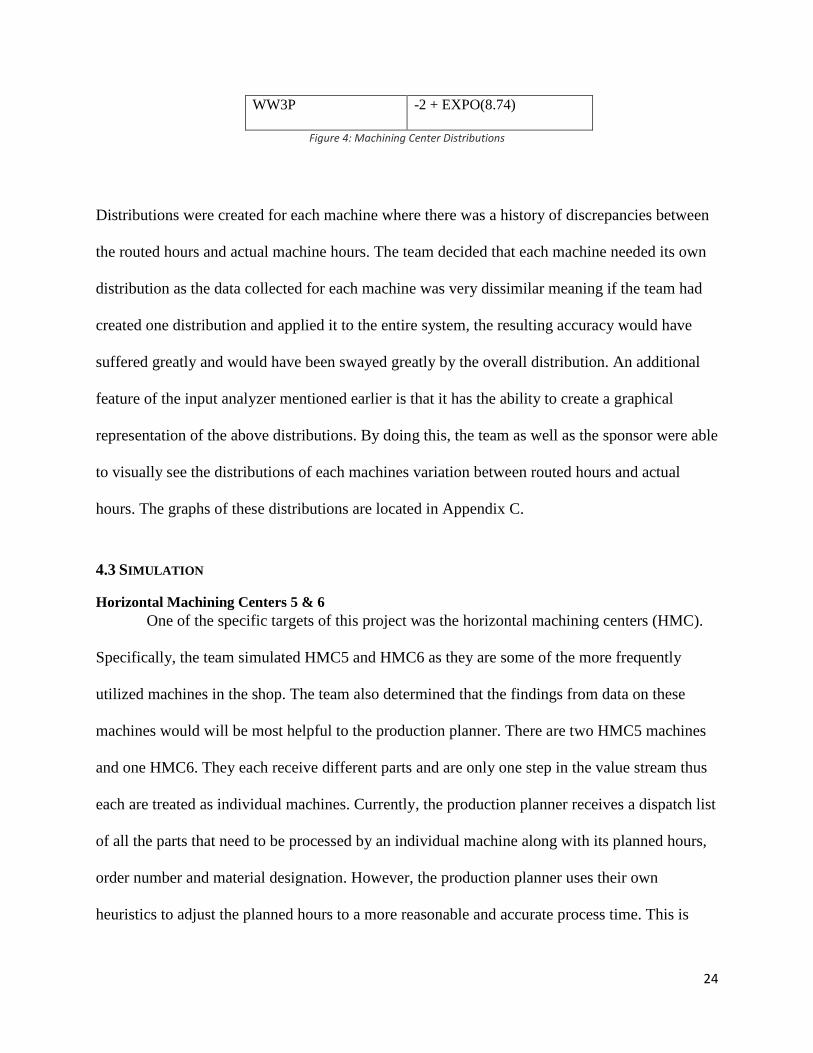
24
WW3P -2 + EXPO(8.74)
Figure 4: Machining Center Distributions
Distributions were created for each machine where there was a history of discrepancies between
the routed hours and actual machine hours. The team decided that each machine needed its own
distribution as the data collected for each machine was very dissimilar meaning if the team had
created one distribution and applied it to the entire system, the resulting accuracy would have
suffered greatly and would have been swayed greatly by the overall distribution. An additional
feature of the input analyzer mentioned earlier is that it has the ability to create a graphical
representation of the above distributions. By doing this, the team as well as the sponsor were able
to visually see the distributions of each machines variation between routed hours and actual
hours. The graphs of these distributions are located in Appendix C.
4.3 SIMULATION
Horizontal Machining Centers 5 & 6
One of the specific targets of this project was the horizontal machining centers (HMC).
Specifically, the team simulated HMC5 and HMC6 as they are some of the more frequently
utilized machines in the shop. The team also determined that the findings from data on these
machines would will be most helpful to the production planner. There are two HMC5 machines
and one HMC6. They each receive different parts and are only one step in the value stream thus
each are treated as individual machines. Currently, the production planner receives a dispatch list
of all the parts that need to be processed by an individual machine along with its planned hours,
order number and material designation. However, the production planner uses their own
heuristics to adjust the planned hours to a more reasonable and accurate process time. This is

25
illustrated in the project plan along with information such as the order and material number,
routed hours and start/ finish date.
The Arena® Program is designed to read the order dispatch list for each machine, process
the read data via a mathematical model/expression, and output actual machine run times. The
outputted data closely matches real machine run times previously developed by the production
planner. The simulation model illustrates the process of materials entering the system and being
processed by a machine, given a certain amount of time. It then shows the total parts finished,
number of parts that entered, the WIP, the queue times and the total production time for each
given part. The parameters are adjusted to a typical work month as described by the production
planner but can be further adjusted. The results are captured in a results sheet output from within
the Arena® program, they also are exported into an excel spreadsheet labeled ‘outputs’.
The basic template (Rockwell, 2016) for the simulation model is as follows:
1. Parts are created at a specific interval. Based on the average routed hours per part, set the
models set to introduce a new part into the system every 15 hours in order to reduce
queue time.
2. Parts are assigned the material number, order number and route number based on the
dispatch list, which is read from an excel document labeled inputs.
3. Each part is processed by the machine at a certain process time. The process time is the
routed hours plus the corresponding distribution for each machine(see Appendix A) to
produce a process time similar to the adjusted time that the production planner usually
makes.

26
4. When the part is completed by the machine, information such as the order number,
material number, total processed time, and routed hours are exported to an excel sheet
labeled ‘outputs’ and then exits the system.
This simulation replaces the process of the production planner applying personal judgment
and only heuristics to calculate the adjusted routed hours for each part for the HMC5 and
HMC6 machines.
Entire Manufacturing System
The Arena® simulation functions off of the data provided by the company. The program
inputs the routes per order based stored route data. As new orders enter the system they are
assigned their correct material number, which also associates the correct routing. The machine
process time, and the next step in the production sequence are programed in within the part
associated material number. All of this inputted data is easily visible in a display screen showing
the layout of the factory (as shown in Appendix B) as orders move through it, wait in queues,
and exit the system. The model is flexible enough to add additional routes and machines. Routes
in the system can be simply modified to include more or less machines and process steps.
Depending on order specific process times, machine queue times will vary. All data in the
system can be easily seen and interpreted after the simulation run is complete.
4.4 MANUFACTURING PROCESS ANALYSIS During the evaluation of the manufacturing process at Primetals, the team recognized that
there are inefficiencies in the manufacturing process that are caused by factors external to the
actual manufacturing process. The problem of bottlenecks within the system is not a centralized
issue with one viable solution, but a problem that must be addressed on various fronts. These
fronts expand across various departments and require a cross departmental effort in an

27
addressing and implementing solutions. When attempting to determine the root cause of what is
hindering the manufacturing process of Primetals, the team determined the following factors;
Tooling and programming (coding), queue times between machining centers, scheduling
limitations, and excess WIP.
Primetals has a serious bottleneck within the process of coding the programs necessary
for machining the various parts. Due to this delay in coding, orders are constantly pushed back
resulting in late orders. This bottleneck is due to a constraint on the amount of programmers, and
the process of requesting a programmer to code. When an order that has an upcoming deadline
does not have the software needed to manufacture it, Primetals is forced to put work on to the
shop floor that is not of the highest priority. Due to this, many parts being manufactured do not
have buyers and result in an overstock of inventory. This unproductive labor also results in large
WIP on the shop floor that hinders the ability of Primetals to complete orders that have a higher
priority when the coding is finished.
Due to the layout of the manufacturing facility and sequences of the various parts
manufactured, queue times of the parts manufactured range from one week to three months. This
is due to the fact that the various parts manufactured require forklift drivers to physically move
the parts between the machines across a shop that spans longer than a football field. Due to
recent layoffs, machine operators have to spend more time moving products around the factory
then they did before. This creates further bottlenecks due to loss of productivity when a machine
is not running.
The team analyzed the financial impact that the bottlenecks described above cause on the
entire manufacturing process. The main financial impact the team has identified is the resulting
loss of sales revenue that occurs any time Primetals incurs when a deadline is not met. The team

28
determined that it would be out of scope to try to calculate individual financial losses in terms of
loss of productivity and wasted time in queue. However, it made more sense to directly address
the core cause of loss of revenue, which is incurred when orders are late.
4.5 FINANCIAL ANALYSIS In analyzing the manufacturing process of Primetals, various financial details were
provided to give insight into what steps within the manufacturing process contribute value and
what steps create waste and delay the process. In analyzing any process, it is important to
consider the financial details in order to improve profitability. When evaluating the Roll Housing
Machining process, many inefficiencies and processes that did not create value to the final
product have been observed.
Before machining can start, a manufacturing program needs to be generated. The trouble
is, there is often a delay in programming and tooling for orders. This results in increased lead
times over the entire process, further delaying orders. This aspect of the manufacturing process is
beyond the scope of the model and project. However, it is a factor that the team had observed
that greatly influences the entire machining process and would greatly reduce the overall lead
time associated with most orders.
As a result of the delay in tooling and programming, a problem arises in regards to
prioritization of jobs. There is a demand to have constant work on the machining floor regardless
if the work is a priority order or a continuation of the spare parts sector of Primetals. Due to this
decision. This further increases the lead time of the job and increases the probability that the job
will be completed late.

29
When analyzing the roll housing machining process, a major component of the process
involves physically the moving of materials from one machine to another across the
manufacturing facility. Overhead cranes and forklifts are required to move the products around
the factory floor. However, due to recent cutbacks in the workforce, the supply of dedicated
material handlers has been greatly reduced resulting in an increased lead time for the various
parts being manufactured. This is because dedicated machinists must leave their workstations to
operate a forklift to move the materials they need to their workstation instead of dedicated
material handlers being present to keep the moving of materials efficient. Because of this
increased lead time, products are often left sitting around the factory waiting to be moved to the
next machining center as the workers who could move said parts are running their assigned
machine tools. This factor also relates back to how much WIP is on the machining floor at any
given time. The more WIP on the machining floor, the more orders that are waiting to be moved.
This results in longer lead times then necessary, increased non-value added time, and a higher
probability that the product will be completed past deadline. There is also much risk associated
leaving the products lying around the factory as this presents a greater risk that these products
will be damaged.
As a consequence of the various factors that result in orders being late and accumulation
of WIP, penalties, shipping fees, and inventory costs accumulate that result in a loss of profit. On
many orders, specifically the custom orders, Primetals is obligated to pay a late delivery penalty.
The percentage varies from contract to contract, but the common percentage is 0.1% of the
equipment value per day (Specht, 2016). An example of how rapidly this penalty accumulates is
the penalty associated with a No Twist Mill. A No Twist Mill costs two million dollars, so a
$2,000/day penalty accumulates until the order is fulfilled (Specht, 2016). The original intentions

30
within our model were to provide a comparison between the current process occurring at
Primetals and our suggested model to reduce the number of orders that were late. This was to be
done by reducing the queue times of orders along with total time in the system. However, due to
the various factors that can result in a late order including, engineering delays, material
shortages, quality issues, lead times that are sold inside of what they actually are, etc., it is
impossible to calculate and model all of the various factors that can result in an order being late.
There are also costs associated with expedited shipping. When expediting orders due to
lateness or an attempt to have the order arrive on time, air freight must be used instead of ocean
freight. While the cost of ocean freight is only concerned with weight, air freight is concerned
with both volume and weight. A reasonable estimate for the cost multiplier of using air freight
versus ocean freight is roughly six times greater the cost (B. Specht, personal communication,
February 18th, 2016). An example of this is the cost to ship to China, who is a frequent customer
of Primetals. When shipping the Roll Housing 150 MM Sizing Mill and the Roll Housing
Machining Assembly, it would cost roughly $750 for both parts. However, when shipping the
items using air freight, the cost would roughly be $4,100. Neither of these figures include fees,
duties, and taxes which have to be paid regardless of how the item is shipped. Other costs to take
into detail are the costs associated with WIP. Figure 5 outlines the total WIP and inventory

31
holding costs over 2015-2016.
Figure 5: Total WIP and Inventory Holding Costs (Authors, 2016)
For one, inventory holding costs are 15% of the total WIP. Given that Primetals has a
turnover rate of 2.41, this translates into turning over their inventory every 151 days (1/2.41 x
365). This results in it taking 5 months for Primetals to sell its entire inventory. By calculating
the rolling average using the interval of 5 months, and taking the average of these rolling
averages, Primetals on average has over $4,000,000 of WIP at any given time. Given that
Primetals has an inventory holding cost of 15%, they are spending $612,600 per month on
average on holding costs. Besides the costs associated with WIP, there is a risk that the parts
could be damaged or become obsolete due to changes in design.
Due to lack of data, including process and transfer times for various parts, an improved
model of the entire manufacturing system to reduce WIP was beyond the scope of our project.
The team was able to calculate maximum and average WIP and inventory holding costs for the
part numbers that had the required information. However, as many parts did not have the

32
required data to create a proper simulation model, these parts were not taken into consideration
and therefore result in an incomplete simulation. The simulation also does not take into account
transfer times which greatly effect queues and WIP. The results the group was able to calculate
regarding this information can be found in Figure 6 below.
Figure 6: WIP and Inventory information per part (Authors, 2016)
However, an improved model of the HMC5 to reduce WIP and inventory holding costs
was possible. The group was supplied with a dispatch list to simulate the parts machined by the
HCM5 along with the average prices associated with these parts. The team took an average value
of all of the parts on the dispatch list allowing for the calculation of inventory holding costs and
the total WIP costs. The number of WIP outputted by the two models was compared. The first
model being a simulation of the current machining process of the HMC5 and the second
simulation modeling our suggested process. This resulted in cost savings for inventory holding
costs and WIP. The cost savings associated with this model are proof of concept that the full
model, given more data, is capable of producing results that are applicable in cost savings. The

33
cost savings of our model of the HCM5 can be found in Figure 7 below:
Figure 7: Cost Savings (Authors, 2016)
When analyzing the overall cost savings associated with our model, other savings occur
besides inventory holding costs that can be estimated, which our model provides. Reduction in
late fees, expedited shipping costs, and a reduction of risk of damaged parts results in an
estimated additional $2,000 savings per month along with the calculated $5,705. There will be an
initial investment of $25,000 to purchase Arena and $12,000 to train an employee on its usage.
Given these factors, Primetals can expect to save $91,037 over a 2 year span based on the capital
recovery equation of A = P(A/P,i,n) which equals 24,000(A/P,10%,8) = 24,000(5.3349) =

34
$128,037. $128,037 minus the initial investment of $37,000 equals $91,037. Figure 8 below
shows the cost savings over 8 quarters.
Figure 8: Cost Savings (Authors, 2016)
Given that this savings only accounts for the HCM5, it is expected that the savings across the
factory would be greater if more data is acquired to input into the simulation.
The current inefficiencies cause ongoing costs within the manufacturing process. One
factor that all of these inefficiencies influence is the reputation Primetals has within the
marketplace due to slipping delivery dates. Primetals can enhance its reputation further by
improving on time delivery and predictability of dates.

35
5. DISCUSSION
The first stage of research and understanding the process proved the most difficult because of
the adjustments occurring at the company. A merger requires a huge company transformation
including the culture and system. This led to many of the following issues the team had
encountered below:
I. The team had the privilege to observe firsthand the challenges in merging
organizations. A merger of sorts between the practices of Siemens against those
practiced by Mitsubishi created a shift of operations and practices. Confusion arose
between common terms and common measurements between the two systems.
Therefore, the team attempted to make a common platform in order to compare the
numbers between the systems and get a somewhat accurate baseline.
II. The lack of documentation presented a challenge. Sometimes it was difficult to
retrieve data necessary for the project. Information such as the average transportation
time or transfer time from one machine to another was not readily available. This
hindered the ability to evaluate-non-value added time and prevented its inclusion in
the simulation. Average set up time per each machine or job was not readily available
as well.
III. Variability from manufacturing operations and human resources also presented other
challenges. Another major issue that the team encountered was inaccurate data
partially due to labor turnover at takt time of the merger. The team made certain
observations that were accurate at the time when they were recorded but, as labor was
relocated they became less accurate. The team attempted to adjust these changes

36
taking into consideration the labor changeover as best as they could, estimates were
used.
The team encompassed many challenges but adapted to overcome them. The team used whatever
data was accessible to develop the simulation program, and used the observations and interviews
with company contacts to perform an analysis. To minimize delays, the team developed plans on
how to address the problem. Once the team received the information, the team was able to
quickly perform our analysis. The team observed firsthand how in the business world sometimes
adjustments are necessary and the team adapted to changing circumstances as information was
made available to the team.

37
6. RECOMMENDATIONS
Throughout this process the team also observed bottlenecks that impact the manufacturing
process that are external to the physical process and beyond the scope of the project. Therefore,
the team arrived at the following recommendations:
1. First, it is suggested that Primetals use simulation software like Arena® for their
forecasting and planning needs. Arena® is relatively simple to use and allows users to
manipulate different parameters such as the hours of operations, resources available,
materials and route hours being inputted and the list continues. These features can
provide Primetals insight on how to go about making changes in the production system
without actually making those physical changes that could incur some cost and risk.
Along with providing insights, the simulation program can allow users, especially the
production planner, the possibility of completing certain jobs within a specific deadline,
the number of jobs that can be completed and eliminates the manual labor associated with
making these types of guesses. In addition to providing insights in regards to forecasting
and planning, Arena® provides the ability to look at results and specific performance
measures such as but not limited to queue time, value added time vs. non-value added
time, transfer time (transportation), machine utilization, and average total time. These are
parameters crucial for continuous improvement and can easily be recorded and
documented. Also, the simulation program is able to read and write to Excel spreadsheets
thus there is the ability to communicate with the simulation program and SAP software
that is currently being used by Primetals. Excel sheets exported from SAP can be
extracted and imported into the simulation program so that accurate and real information
is being used. Then results can be extracted from the simulation program and be

38
documented and analyzed for future purposes. In conclusion, the team highly
recommends Primetals invest in Arena®.
2. Second, a set of heuristics need to be defined for the priority rule for jobs regarding
tooling, programming, scheduling work, and rules for machining. The team highly
recommends open lines of communication between the different departments including
production, manufacturing, quality, sales and human resources. After discussion, a
consensus of rules for which jobs are priority and require tooling and programming first
should be set. Also, there could be a rule on the amount of WIP that could be on the floor
and jobs that can be started to increase flexibility within scheduling. Lastly, there needs
to be rules for machining, which can be evaluated via the simulation program, on whether
some jobs should be batched or if the HMC5 should run on first-in-first-out among both
machines, or if each should continue to operate independently of each another and have
their own distinct dispatch lists. All of these heuristics will require the full collaboration
of various departments.
3. The last alternative solution is to expand the use of SAP. SAP has the capability of
facilitating capacity planning and production planning similar to that of Arena®.
However, it will require a greater commitment to conduct the necessary training.

39
7. CONCLUSION
There were three major findings as a result of the project. The first is that Primetals can better
understand their manufacturing capacity and capability by use of a simulation program like
Arena®. After analyzing the current manufacturing process of the roller housing assemblies and
the horizontal machining centers, the team developed a model using Arena® simulation
software. Within the simulation program, the team was able to quantify heuristics into a
mathematical distribution. These heuristics were typically inputted manually by the production
planner. The simulation will allow the production planner to more easily forecast and strategically
plan short term production runs for the HMC5 and HMC6 machining centers without the need to
create them by hand. The team delivered the project goals by creating three simulation programs.
One for the HMC5 center, one for the HMC6 center, and a final model for the roller house
assembly manufacturing process.
The second major finding is that reducing shop floor headcount shifts value added work away
from its high level employees, and reduces their efficiency. Machinists create the most value
when running a machine, so any time spent doing material handling is time lost that could have
been put towards production. In addition to creating a bottleneck of to-be-moved products,
efficiency is also reduced due to programming constraints. The shop floor has a major bottleneck
within the tooling and programming department. The tool part coding takes days to create. This
can halt production if orders aren't planned out correctly. The company is then forced to put
work on to the shop floor that is not of the highest deliverable priority. When the tooling and
programming is ready, there then may be a lot of WIP on the machining floor interfering with the
job. The risk with leaving WIP on the factory floors includes; increased chance of damage,
crowding operator workspace, crammed isle-ways, and loss of products. This greatly influences

40
the entire machining process, and increases the overall lead time associated with most orders.
Increasing the number of operators on the floor may cost more money up front, but could
potentially save the company money in the long run. Third, a reasonable value of the
inefficiencies in any production system can be quantified to understand the financial magnitude
of the problem at hand.

41
8. REFERENCES
Axiomatic Design Solutions, Inc. "Acclaro software." 221 North Beacon Street Brighton, MA
02135 www.axiomaticdesign.com, 2015.
Brofford, K., Devries, J., Rovayo, L., & Vergara, S. (2015). Lean Proccess Improvement of Roll
Housing Manufacturing (Unpublished doctoral dissertation). Worcester Polytechnic
Institute.
Discrete Event Simulation Software. (n.d.). Retrieved December 1, 2015, from
https://www.arenasimulation.com/what-is-simulation/discrete-event-simulation-software
Konrad, R. (2014, October 15). Session 1: Simulation Basics. Lecture presented at OIE 3460:
Simulation Modeling & Analysis in Worcester Polytechnic Institute, Worcester.
Kelton, W. D., Sadowski, R. P., & Zupick, N. B. (2014). Simulation with Arena (6th ed.).
McGraw Hill Higher Education.
Lavinsky, D. (2014, January 20). Pareto Principle: How To Use It To Dramatically Grow Your
Business. Retrieved January 3, 2016, from
http://www.forbes.com/sites/davelavinsky/2014/01/20/pareto-principle-how-to-use-it-to
dramatically-grow-your-business/#716c3de61259
Manufacturing Scheduling and Planning Software. (n.d.). Retrieved October 6, 2015, from
http://www.iqms.com/products/erp/manufacturing/scheduling/index.html
Production Scheduling Software. (n.d.). Retrieved October 7, 2015, from http://www.waterloo
software.com/production-scheduling-software/
Rockwell Automation. (2014). Arena Simulation Software (Version 14.70.00) [Computer
software]. Retrieved October 03, 2015, from https://www.arenasimulation.com/
Rockwell Automation: Our History. (n.d.). Retrieved December 1, 2015, from
http://www.rockwellautomation.com/global/about-us/history/overview.page
Scheduling made easy. (n.d.). Retrieved October 9, 2015, from
http://www.optessa.com/technology/optimization
Specht, B. (2016, February 04). Financial Data Questioning [Personal interview].
Suh (1990), The Principles of Design, Oxford University Press, 1990, ISBN 0-19-504345-6
Towner, W. (2013). Axiomatic Design Introduction. Lecture presented at MFE520/ME543 in
Worcester Polytechnic Institute, Worcester.
Towner, W. (2013). Decomposition in Axiomatic Design. Lecture presented at MFE520/ME543
in Worcester Polytechnic Institute, Worcester.

42
9. APPENDIX A – SIMULATION ONE HMC5 & HMC 6
PROCESS FOR HMC5 & HMC6
SIMULATION CODE FOR HMC5 AND HMC6
PARTIAL HMC5 & HMC6 RESULTS FOR DISPATCH LIST 02-01-16
Parts enter at
time interval
Inputs are assigned
Processed by
Machine
Outputs are
exported;
Parts exit system

43
10. APPENDIX B – RHA MANUFACTURING PROCESS
ENTIRE RHA SIMULATION

44
SIMULATION LOGIC FOR RHA MANUFACTURING PROCESS

45
RESULTS OF RHA SIMULATION

46
11. APPENDIX C – MATHEMATICAL MODEL
ORIGINAL DATA
This is a sample of the data the team used to create the distributions used for the model. In total,
this list has actual hours and routed hours for jobs dating back to January 2013 and as recent as
December 2015. This data was combined with some current dispatch lists as well as project files
given to the team by a planner at Primetals.

47
HMC5: -4+79*BETA(0.545, 1.25)
HMC6: -7 + WEIB(12.7, 2.08)
HH40: 1+ WEIB(28.8, 1.19)

48
L74R: TRIA(-1, 1.4, 6.99)
A71M: -6 + 21*BETA(5.73, 11.3)
WW3P: -2+EXPO(8.74)

49
HH6S: -7 + 30*BETA(2.64, 1.55)
The above graphs are representations of differences between the actual run hours of machines
and the current routed hours for operations within SAP. These graphs were generated with the
best fit function in the input analyzer application. As can be seen above, each machine had very
different data that led to a variety of distributions. The team used this in order to adjust the
routed hours that the Arena simulation pulled from the excel files provided to the team by
Primetals.