Manufacturing Automation Computer Numerical Control (CNC) Dr. Lotfi K. Gaafar.
64
Manufacturing Automation Computer Numerical Control (CNC) Dr. Lotfi K. Gaafar
-
Upload
howard-cobb -
Category
Documents
-
view
219 -
download
1
Transcript of Manufacturing Automation Computer Numerical Control (CNC) Dr. Lotfi K. Gaafar.

Manufacturing Automation
Computer Numerical Control (CNC)
Dr. Lotfi K. Gaafar
Overview
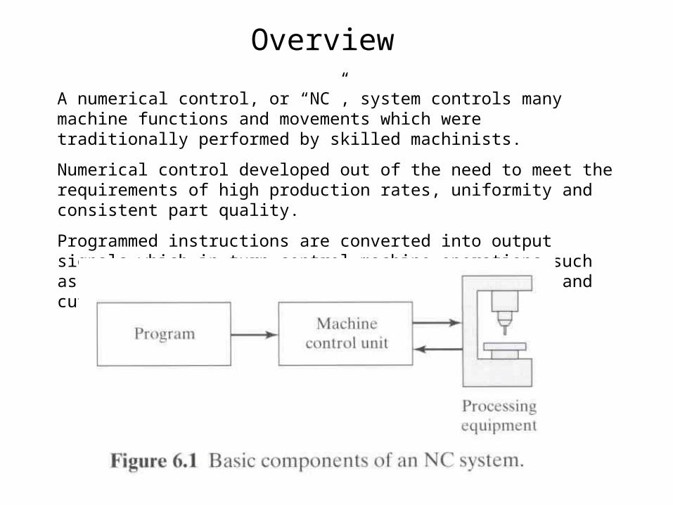
A numerical control, or “NC”, system controls many machine functions and movements which were traditionally performed by skilled machinists.
Numerical control developed out of the need to meet the requirements of high production rates, uniformity and consistent part quality.
Programmed instructions are converted into output signals which in turn control machine operations such as spindle speeds, tool selection, tool movement, and cutting fluid flow.
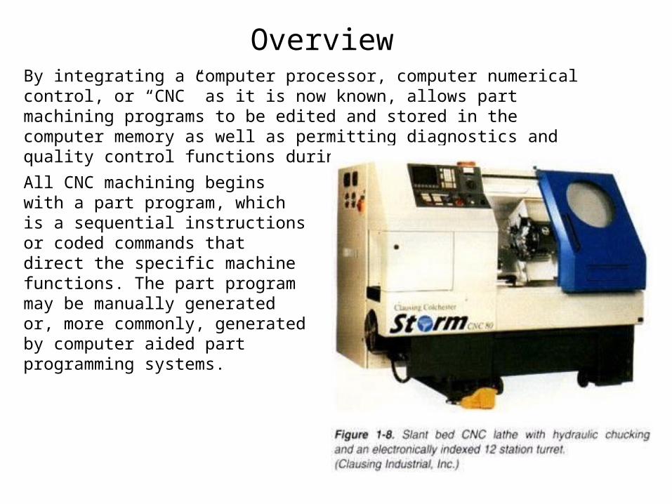
OverviewBy integrating a computer processor, computer numerical control, or “CNC” as it is now known, allows part machining programs to be edited and stored in the computer memory as well as permitting diagnostics and quality control functions during the actual machining.
All CNC machining begins with a part program, which is a sequential instructions or coded commands that direct the specific machine functions. The part program may be manually generated or, more commonly, generated by computer aided part programming systems.
Basic CNC Principles
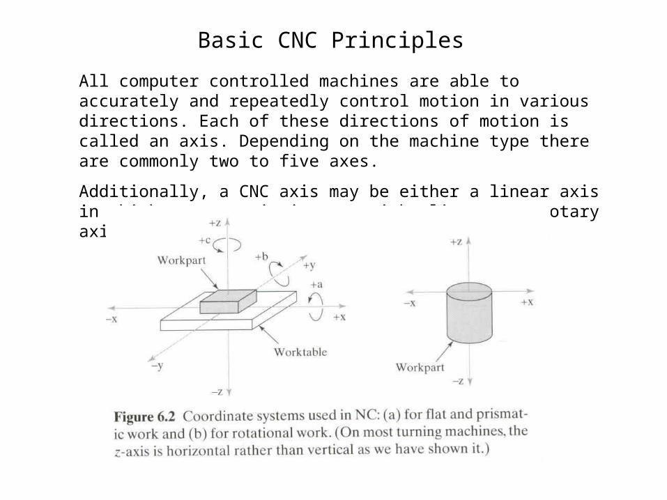
All computer controlled machines are able to accurately and repeatedly control motion in various directions. Each of these directions of motion is called an axis. Depending on the machine type there are commonly two to five axes.
Additionally, a CNC axis may be either a linear axis in which movement is in a straight line, or a rotary axis with motion following a circular path.

Basic CNC Principles
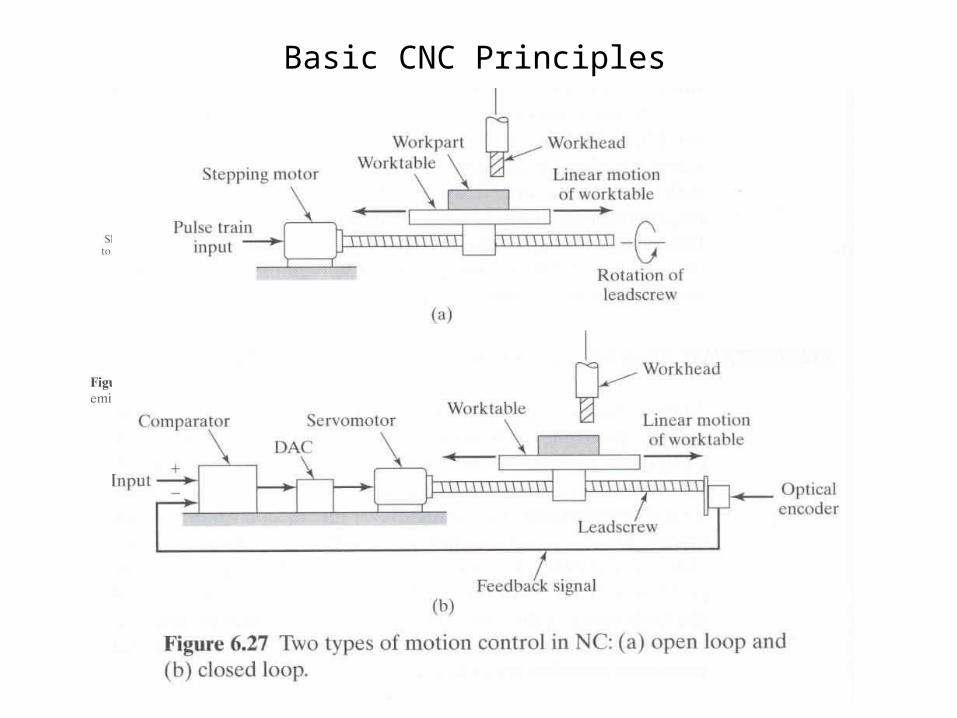
Each axis consists of a mechanical component, such as a slide that moves, a servo drive motor that powers the mechanical movement, and a ball screw to transfer the power from the servo drive motor to the mechanical component. These components, along with the computer controls that govern them, are referred to as an axis drive system.

Basic CNC PrinciplesUsing a vertical mill machining center as an example, there are typically three linear axes of motion. Each is given an alphabetic designation or address. The machine table motion side to side is called the “X” axis. Table movement in and out is the “Y” axis, while head movement up and down the column is the “Z” axis.
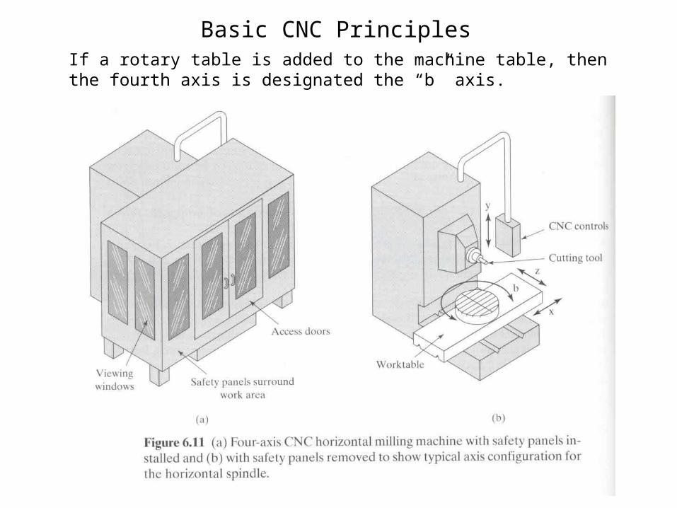
Basic CNC PrinciplesIf a rotary table is added to the machine table, then the fourth axis is designated the “b” axis.

The method of accurate work positioning in relation to the cutting tool is called the “rectangular coordinate system.” On the vertical mill, the horizontal base line is designated the “X” axis, while the vertical base line is designated the “Y” axis. The “Z” axis is at a right angle, perpendicular to both the “X” and “Y” axes.Increments for all base lines are specified in linear measurements, for most machines the smallest increment is one ten-thousandth of an inch (.0001). If the machine is graduated in metric the smallest increment is usually one thousandth of a millimeter (.001mm).The rectangular coordinate system allows the mathematical plotting of points in space. These points or locations are called “coordinates.” The coordinates in turn relate to the tool center and dictate the “tool path” through the work.
Work Positioning
Basic CNC Principles

CNC instructions are called part program commands.
When running, a part program is interpreted one command line at a time until all lines are completed.
Commands, which are also referred to as blocks, are made up of words which each begin with a letter address and end with a numerical value.
Each letter address relates to a specific machine function. “G” and “M” letter addresses are two of the most common. A “G” letter specifies certain machine preparations such as inch or metric modes, or absolutes versus incremental modes.
A “M” letter specifies miscellaneous machine functions and work like on/off switches for coolant flow, tool changing, or spindle rotation. Other letter addresses are used to direct a wide variety of other machine commands.
CNC Programming Basics

Optimum machine programming requires consideration of certain machine operating parameters including:• Positioning control• Compensations• Special machine featuresPositioning control is the ability to program tool and machine slide movement simultaneously along two or more axes. Positioning may be for point-to-point movement or for contouring movement along a continuous path. Contouring requires tool movement along multiple axes simultaneously. This movement is referred to as “Interpolation” which is the process of calculating intermediate values between specific points along a programmed path and outputting those values as a precise motion. Interpolation may be linear having just a start and end point along a straight line, or circular which requires an end point, a center and a direction around the arc.
Program Command Parameters

Two computer-based systems which impact the use of CNC technology are computer aided design and computer aided manufacturing.A computer aided design, or CAD, system uses computers to graphically create product designs and models. These designs can be reviewed, revised, and refined for optimum end use and application. Once finalized, the CAD design is then exported to a computer aided manufacturing, or CAM, system.CAM systems assist in all phases of manufacturing a product, including process planning, production planning, machining, scheduling, management and quality control.
CAD/CAM

APT Programming ExampleCylindrical Part
25
22.5
17.5
20
Raw Material
Finished Part
70
30
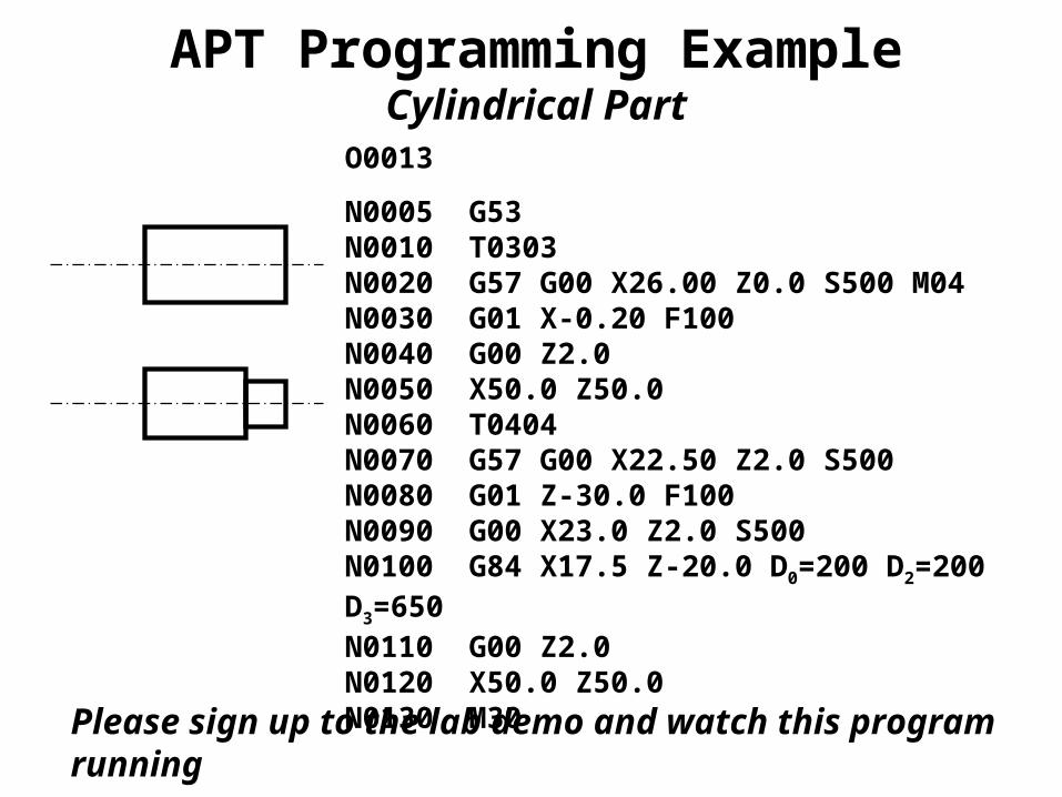
APT Programming ExampleCylindrical Part
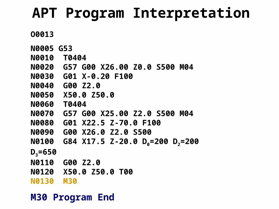
O0013
N0005 G53N0010 T0303N0020 G57 G00 X26.00 Z0.0 S500 M04N0030 G01 X-0.20 F100N0040 G00 Z2.0N0050 X50.0 Z50.0N0060 T0404N0070 G57 G00 X22.50 Z2.0 S500 N0080 G01 Z-30.0 F100N0090 G00 X23.0 Z2.0 S500N0100 G84 X17.5 Z-20.0 D0=200 D2=200 D3=650N0110 G00 Z2.0N0120 X50.0 Z50.0 N0130 M30
Please sign up to the lab demo and watch this program running

APT Program InterpretationO0013
Program identification number
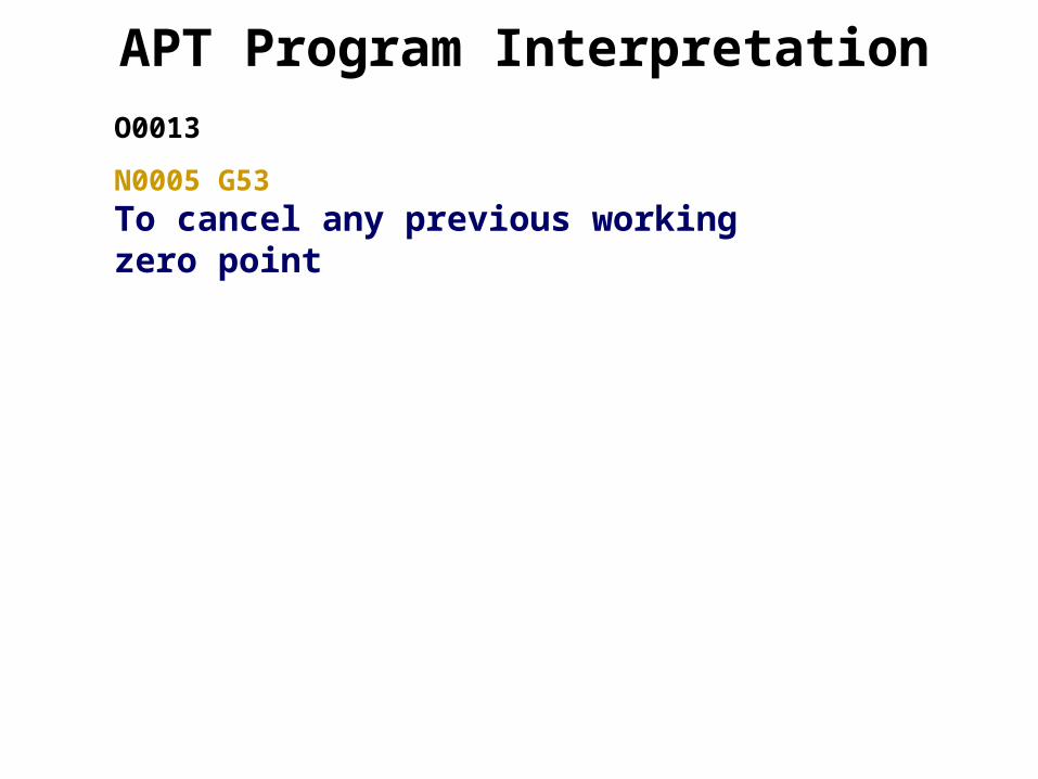
APT Program InterpretationO0013
N0005 G53
To cancel any previous working zero point

APT Program InterpretationO0013N0005 G53N0010 T0303
N0010 Sequence numberT0303 Select tool number 303

O0013
N0005 G53 N0010 T0404N0020 G57 G00 X26.0 Z0.0 S500 M04
G57 To set the working zero point as saved G00 Rapid movement (no cutting)X26.0 X location (as a diameter; 13 form zero)Z0.0 Z locationS500 Spindle speed is 500 rpmM04 Rotate spindle counterclockwise
APT Program Interpretation
x
z(0,0) +ve
+ve

O0013
N0005 G53
N0010 T0404N0020 G57 G00 X26.00 Z0.0 S500 M04N0030 G01 X-0.20 F100
G01 Linear interpolation (cutting)X-0.20 Move only in x direction until you pass the center by 0.1 mm (facing)F100 Set feed rate to 100 mm/min.
APT Program Interpretation
O0013N0005 G53
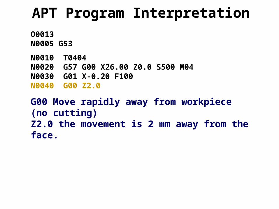
N0010 T0404N0020 G57 G00 X26.00 Z0.0 S500 M04N0030 G01 X-0.20 F100N0040 G00 Z2.0
G00 Move rapidly away from workpiece (no cutting)Z2.0 the movement is 2 mm away from the face.
APT Program Interpretation
O0013
N0005 G53
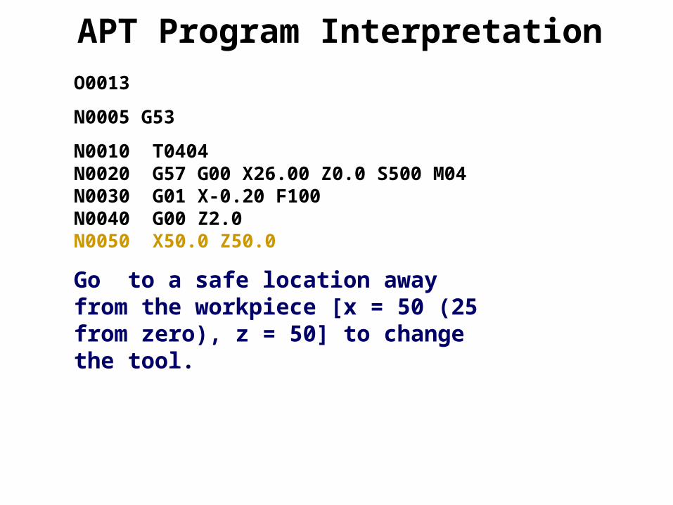
N0010 T0404N0020 G57 G00 X26.00 Z0.0 S500 M04N0030 G01 X-0.20 F100N0040 G00 Z2.0N0050 X50.0 Z50.0
Go to a safe location away from the workpiece [x = 50 (25 from zero), z = 50] to change the tool.
APT Program Interpretation

O0013
N0005 G53 N0010 T0404N0020 G57 G00 X26.00 Z0.0 S500 M04N0030 G01 X-0.20 F100N0040 G00 Z2.0N0050 X50.0 Z50.0N0060 T0404
T0404 Select tool number 404
APT Program Interpretation
O0013
N0005 G53
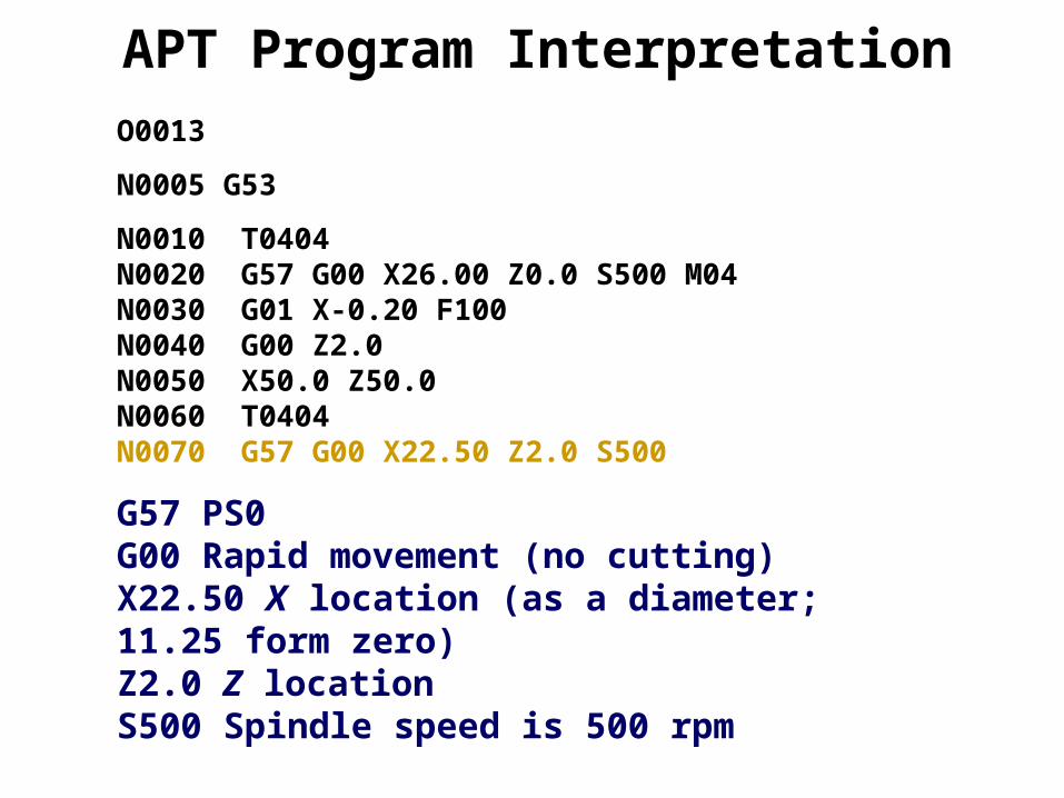
N0010 T0404N0020 G57 G00 X26.00 Z0.0 S500 M04N0030 G01 X-0.20 F100N0040 G00 Z2.0N0050 X50.0 Z50.0N0060 T0404N0070 G57 G00 X22.50 Z2.0 S500
G57 PS0 G00 Rapid movement (no cutting)X22.50 X location (as a diameter; 11.25 form zero)Z2.0 Z locationS500 Spindle speed is 500 rpm
APT Program Interpretation

O0013
N0005 G53
N0010 T0404N0020 G57 G00 X26.00 Z0.0 S500 M04N0030 G01 X-0.20 F100N0040 G00 Z2.0N0050 X50.0 Z50.0N0060 T0404N0070 G57 G00 X25.00 Z2.0 S500 M04N0080 G01 Z-30.0 F100
G01 Linear interpolation (cutting)Z-30 Move only in z direction (external turning)F100 Set feed rate to 100 mm/min.
APT Program Interpretation

O0013
N0005 G53
N0010 T0404N0020 G57 G00 X26.00 Z0.0 S500 M04N0030 G01 X-0.20 F100N0040 G00 Z2.0N0050 X50.0 Z50.0N0060 T0404N0070 G57 G00 X25.00 Z2.0 S500 M04N0080 G01 X22.5 Z-70.0 F100N0090 G00 X23.0 Z2.0 S500
G00 Move rapidly away from workpiece (no cutting) to location x= 23.0 (11.50 from zero) and z = 2.0.
APT Program Interpretation
O0013
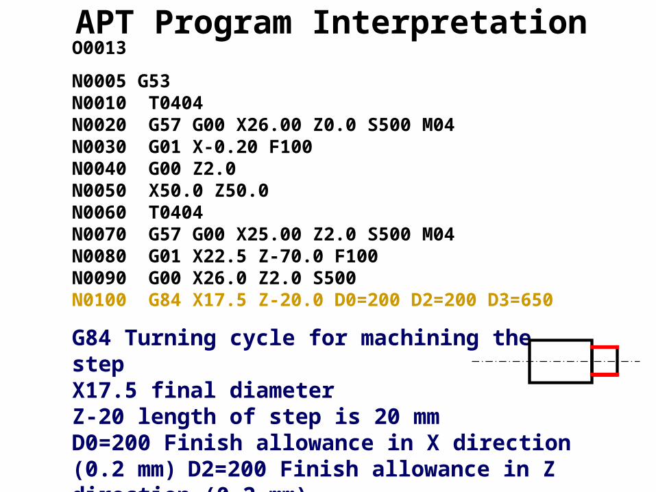
N0005 G53 N0010 T0404N0020 G57 G00 X26.00 Z0.0 S500 M04N0030 G01 X-0.20 F100N0040 G00 Z2.0N0050 X50.0 Z50.0N0060 T0404N0070 G57 G00 X25.00 Z2.0 S500 M04N0080 G01 X22.5 Z-70.0 F100N0090 G00 X26.0 Z2.0 S500N0100 G84 X17.5 Z-20.0 D0=200 D2=200 D3=650
G84 Turning cycle for machining the stepX17.5 final diameterZ-20 length of step is 20 mmD0=200 Finish allowance in X direction (0.2 mm) D2=200 Finish allowance in Z direction (0.2 mm)D3=650 Depth of cut in each pass (0.65 mm)
APT Program Interpretation
O0013
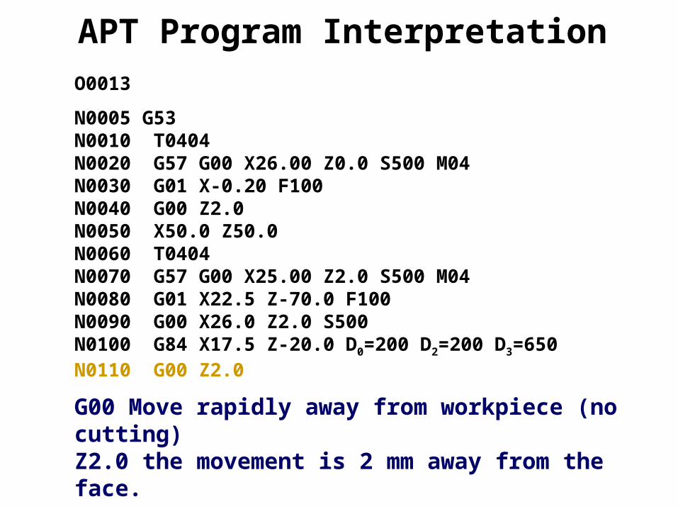
N0005 G53 N0010 T0404N0020 G57 G00 X26.00 Z0.0 S500 M04N0030 G01 X-0.20 F100N0040 G00 Z2.0N0050 X50.0 Z50.0N0060 T0404N0070 G57 G00 X25.00 Z2.0 S500 M04N0080 G01 X22.5 Z-70.0 F100N0090 G00 X26.0 Z2.0 S500N0100 G84 X17.5 Z-20.0 D0=200 D2=200 D3=650N0110 G00 Z2.0
G00 Move rapidly away from workpiece (no cutting)Z2.0 the movement is 2 mm away from the face.
APT Program Interpretation
O0013
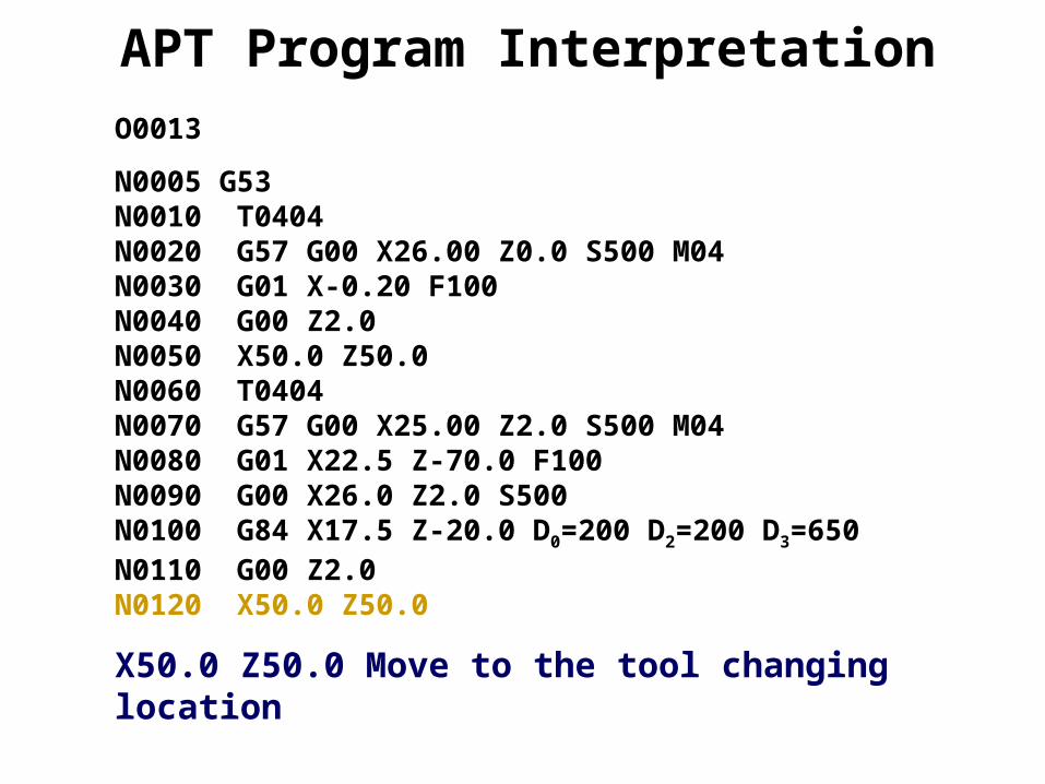
N0005 G53 N0010 T0404N0020 G57 G00 X26.00 Z0.0 S500 M04N0030 G01 X-0.20 F100N0040 G00 Z2.0N0050 X50.0 Z50.0N0060 T0404N0070 G57 G00 X25.00 Z2.0 S500 M04N0080 G01 X22.5 Z-70.0 F100N0090 G00 X26.0 Z2.0 S500N0100 G84 X17.5 Z-20.0 D0=200 D2=200 D3=650N0110 G00 Z2.0N0120 X50.0 Z50.0
X50.0 Z50.0 Move to the tool changing location
APT Program Interpretation
O0013
N0005 G53 N0010 T0404N0020 G57 G00 X26.00 Z0.0 S500 M04N0030 G01 X-0.20 F100N0040 G00 Z2.0N0050 X50.0 Z50.0N0060 T0404N0070 G57 G00 X25.00 Z2.0 S500 M04N0080 G01 X22.5 Z-70.0 F100N0090 G00 X26.0 Z2.0 S500N0100 G84 X17.5 Z-20.0 D0=200 D2=200 D3=650N0110 G00 Z2.0N0120 X50.0 Z50.0 T00N0130 M30
M30 Program End
APT Program Interpretation

Programming Example
Raw Material Finished Part

Programming Example
G55 X200 Y80Program 1N001 M06 T1N002 M03 rpm 400N003 G01 X-8 Y0 Z0 XYFeed 150N004 G01 X-8 Y0 Z-0.5 ZFeed 150N005 G01 X70 Y0 Z-0.5 XYFeed 75N006 G01 X70 Y60 Z-0.5 XYFeed 75N007 G01 X30 Y60 Z-0.5 XYFeed 75N008 G01 X0 Y40 Z-0.5 XYFeed 75N009 G01 X0 Y0 Z-0.5 XYFeed 75N010 G81 R3 E9 N7 Z-0.5N011 M05N012 M02
x
y

Programming Example
Tool ChangeG55 X200 Y80Program 2N001 M06 T2N002 M03 rpm 400N003 G01 X-8 Y0 Z0 XYFeed 150N004 G01 X20 Y15 Z10 XYFeed 150 ZFeed 150N005 G01 X20 Y15 Z-10 ZFeed 75N006 G01 X20 Y15 Z10 ZFeed 150N007 G01 X50 Y15 Z10 ZFeed 150N008 G01 X50 Y15 Z-10 ZFeed 75N009 G01 X50 Y15 Z10 ZFeed 150N010 G01 X50 Y45 Z10 ZFeed 150N011 G01 X50 Y45 Z-10 ZFeed 75N012 G01 X50 Y45 Z10 ZFeed 150N013 M05N014 M02
x
y

Program InterpretationG55 X200 Y80
Setting the datum to the lower left corner of the work piece
Program InterpretationG55 X200 Y80Program 1
Program Identification Number
Program InterpretationG55 X200 Y80Program 1N001 M06 T1
N001 Sequence NumberM06 Tool Change (End Mill with
Diameter=12mmT1 Tool Number
Program InterpretationG55 X200 Y80Program 1N001 M06 T1N002 M03 rpm 400
Start rotating the spindle clockwise with 400 rpm

Program InterpretationG55 X200 Y80Program 1N001 M06 T1N002 M03 rpm 400N003 G01 X-8 Y0 Z0 XYFeed 150
Go to Safe Position with feed 150mm/min
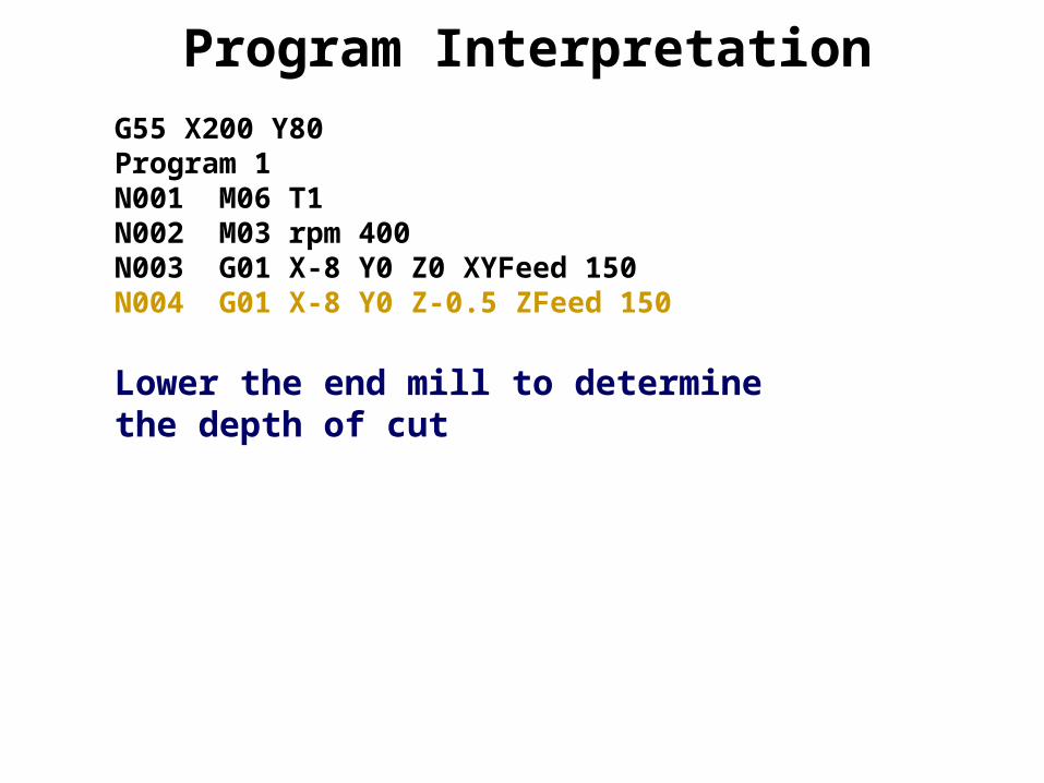
Program InterpretationG55 X200 Y80Program 1N001 M06 T1N002 M03 rpm 400N003 G01 X-8 Y0 Z0 XYFeed 150N004 G01 X-8 Y0 Z-0.5 ZFeed 150
Lower the end mill to determine the depth of cut

Program InterpretationG55 X200 Y80Program 1N001 M06 T1N002 M03 rpm 400N003 G01 X-8 Y0 Z0 XYFeed 150N004 G01 X-8 Y0 Z-0.5 ZFeed 150N005 G01 X70 Y0 Z-0.5 XYFeed 75
Move from the lower left corner of the work piece to the right lower one cutting with feed=75mm/min

Program InterpretationG55 X200 Y80Program 1N001 M06 T1N002 M03 rpm 400N003 G01 X-8 Y0 Z0 XYFeed 150N004 G01 X-8 Y0 Z-0.5 ZFeed 150N005 G01 X70 Y0 Z-0.5 XYFeed 75N006 G01 X70 Y60 Z-0.5 XYFeed 75
Move from the lower left corner of the work piece to the right lower one cutting with feed=75mm/min
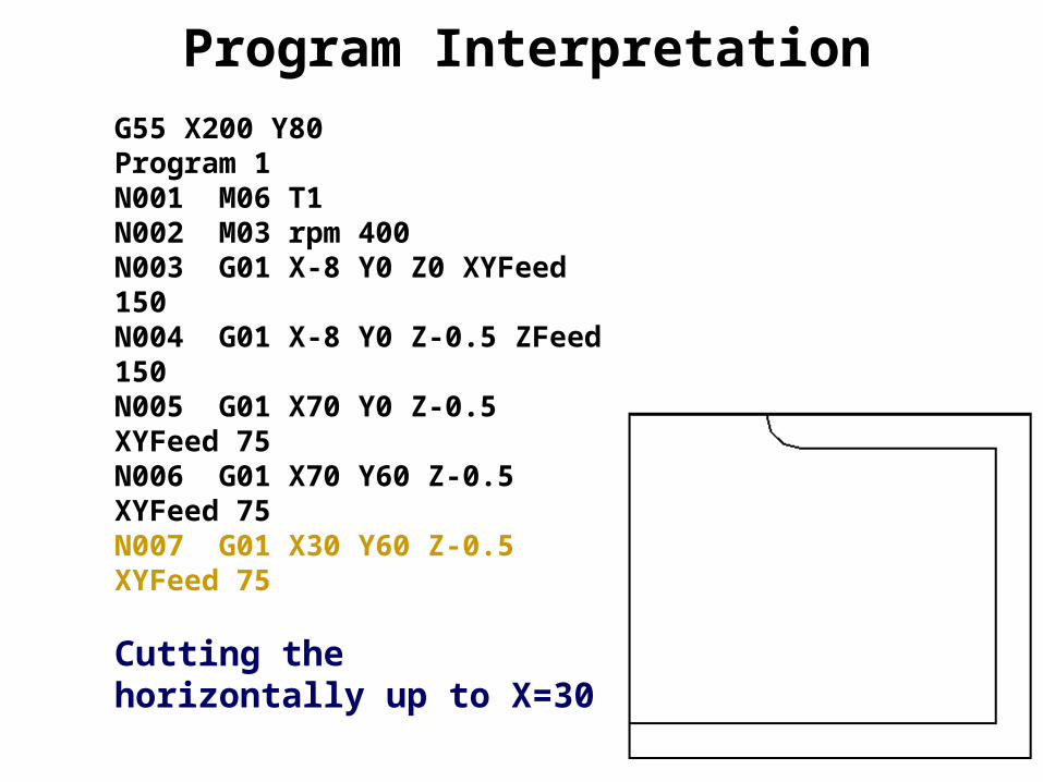
Program InterpretationG55 X200 Y80Program 1N001 M06 T1N002 M03 rpm 400N003 G01 X-8 Y0 Z0 XYFeed 150N004 G01 X-8 Y0 Z-0.5 ZFeed 150N005 G01 X70 Y0 Z-0.5 XYFeed 75N006 G01 X70 Y60 Z-0.5 XYFeed 75N007 G01 X30 Y60 Z-0.5 XYFeed 75
Cutting the horizontally up to X=30

Program InterpretationG55 X200 Y80Program 1N001 M06 T1N002 M03 rpm 400N003 G01 X-8 Y0 Z0 XYFeed 150N004 G01 X-8 Y0 Z-0.5 ZFeed 150N005 G01 X70 Y0 Z-0.5 XYFeed 75N006 G01 X70 Y60 Z-0.5 XYFeed 75N007 G01 X30 Y60 Z-0.5 XYFeed 75N008 G01 X0 Y40 Z-0.5 XYFeed 75
Cutting to X=0 & Y=40
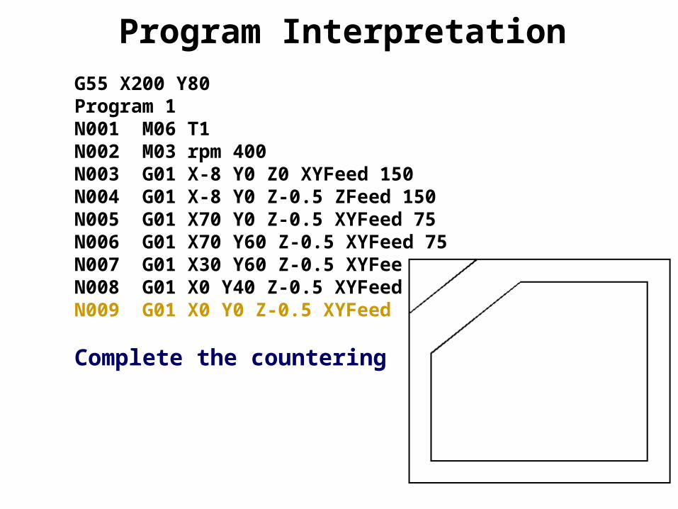
Program InterpretationG55 X200 Y80Program 1N001 M06 T1N002 M03 rpm 400N003 G01 X-8 Y0 Z0 XYFeed 150N004 G01 X-8 Y0 Z-0.5 ZFeed 150N005 G01 X70 Y0 Z-0.5 XYFeed 75N006 G01 X70 Y60 Z-0.5 XYFeed 75N007 G01 X30 Y60 Z-0.5 XYFeed 75N008 G01 X0 Y40 Z-0.5 XYFeed 75N009 G01 X0 Y0 Z-0.5 XYFeed 75
Complete the countering
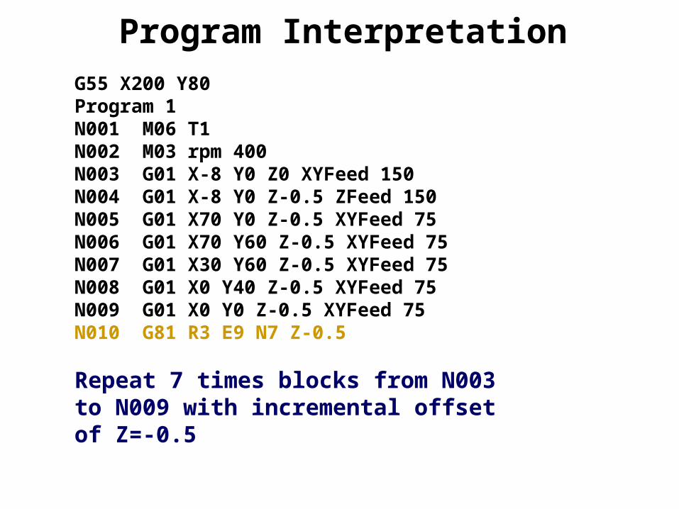
Program InterpretationG55 X200 Y80Program 1N001 M06 T1N002 M03 rpm 400N003 G01 X-8 Y0 Z0 XYFeed 150N004 G01 X-8 Y0 Z-0.5 ZFeed 150N005 G01 X70 Y0 Z-0.5 XYFeed 75N006 G01 X70 Y60 Z-0.5 XYFeed 75N007 G01 X30 Y60 Z-0.5 XYFeed 75N008 G01 X0 Y40 Z-0.5 XYFeed 75N009 G01 X0 Y0 Z-0.5 XYFeed 75N010 G81 R3 E9 N7 Z-0.5
Repeat 7 times blocks from N003 to N009 with incremental offset of Z=-0.5

Program InterpretationG55 X200 Y80Program 1N001 M06 T1N002 M03 rpm 400N003 G01 X-8 Y0 Z0 XYFeed 150N004 G01 X-8 Y0 Z-0.5 ZFeed 150N005 G01 X70 Y0 Z-0.5 XYFeed 75N006 G01 X70 Y60 Z-0.5 XYFeed 75N007 G01 X30 Y60 Z-0.5 XYFeed 75N008 G01 X0 Y40 Z-0.5 XYFeed 75N009 G01 X0 Y0 Z-0.5 XYFeed 75N010 G81 R3 E9 N7 Z-0.5N011 M05
Spindle Off

Program InterpretationG55 X200 Y80Program 1N001 M06 T1N002 M03 rpm 400N003 G01 X-8 Y0 Z0 XYFeed 150N004 G01 X-8 Y0 Z-0.5 ZFeed 150N005 G01 X70 Y0 Z-0.5 XYFeed 75N006 G01 X70 Y60 Z-0.5 XYFeed 75N007 G01 X30 Y60 Z-0.5 XYFeed 75N008 G01 X0 Y40 Z-0.5 XYFeed 75N009 G01 X0 Y0 Z-0.5 XYFeed 75N010 G81 R3 E9 N7 Z-0.5N011 M05N012 M02
End Program

Program InterpretationTool Change
Changing the tool
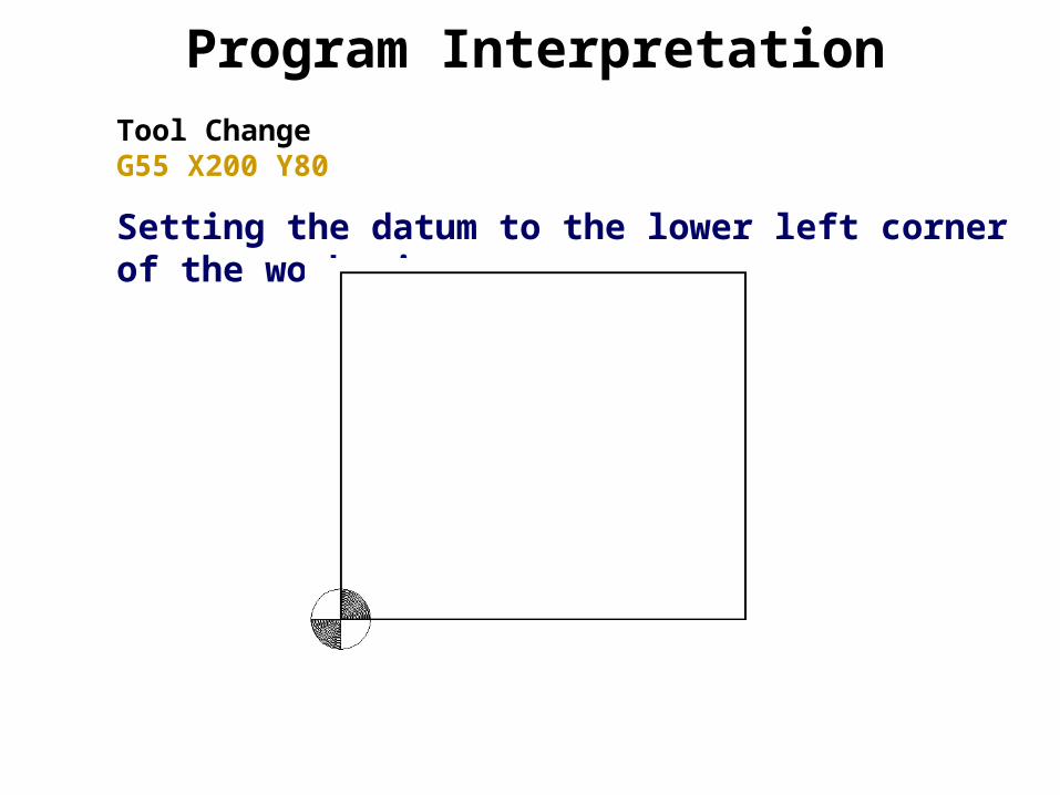
Program InterpretationTool ChangeG55 X200 Y80
Setting the datum to the lower left corner of the work piece

Program InterpretationTool ChangeG55 X200 Y80Program 2
Program Identification Number
Program InterpretationTool ChangeG55 X200 Y80Program 2N001 M06 T2
N001 Sequence NumberM06 Tool Change (Drill with Diameter=6mmT2 Tool Number
Program InterpretationTool ChangeG55 X200 Y80Program 2N001 M06 T2N002 M03 rpm 400
Start rotating the spindle clockwise with 400 rpm
Program InterpretationTool ChangeG55 X200 Y80Program 2N001 M06 T2N002 M03 rpm 400N003 G01 X-8 Y0 Z0 XYFeed 150
Go to Safe Position with feed 150mm/min
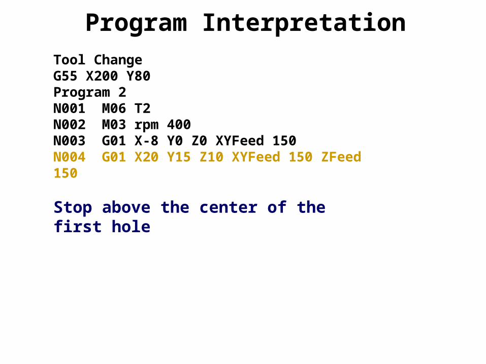
Program InterpretationTool ChangeG55 X200 Y80Program 2N001 M06 T2N002 M03 rpm 400N003 G01 X-8 Y0 Z0 XYFeed 150N004 G01 X20 Y15 Z10 XYFeed 150 ZFeed 150
Stop above the center of the first hole
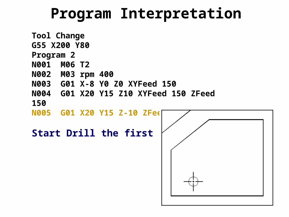
Program InterpretationTool ChangeG55 X200 Y80Program 2N001 M06 T2N002 M03 rpm 400N003 G01 X-8 Y0 Z0 XYFeed 150N004 G01 X20 Y15 Z10 XYFeed 150 ZFeed 150N005 G01 X20 Y15 Z-10 ZFeed 75
Start Drill the first hole
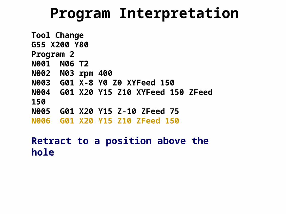
Program InterpretationTool ChangeG55 X200 Y80Program 2N001 M06 T2N002 M03 rpm 400N003 G01 X-8 Y0 Z0 XYFeed 150N004 G01 X20 Y15 Z10 XYFeed 150 ZFeed 150N005 G01 X20 Y15 Z-10 ZFeed 75N006 G01 X20 Y15 Z10 ZFeed 150
Retract to a position above the hole

Program InterpretationTool ChangeG55 X200 Y80Program 2N001 M06 T2N002 M03 rpm 400N003 G01 X-8 Y0 Z0 XYFeed 150N004 G01 X20 Y15 Z10 XYFeed 150 ZFeed 150N005 G01 X20 Y15 Z-10 ZFeed 75N006 G01 X20 Y15 Z10 ZFeed 150N007 G01 X50 Y15 Z10 ZFeed 150
Stop above the center of the second hole
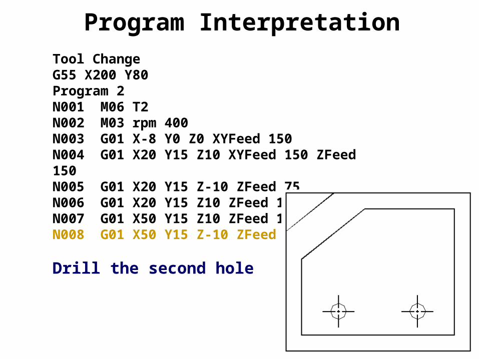
Program InterpretationTool ChangeG55 X200 Y80Program 2N001 M06 T2N002 M03 rpm 400N003 G01 X-8 Y0 Z0 XYFeed 150N004 G01 X20 Y15 Z10 XYFeed 150 ZFeed 150N005 G01 X20 Y15 Z-10 ZFeed 75N006 G01 X20 Y15 Z10 ZFeed 150N007 G01 X50 Y15 Z10 ZFeed 150N008 G01 X50 Y15 Z-10 ZFeed 75
Drill the second hole

Program InterpretationTool ChangeG55 X200 Y80Program 2N001 M06 T2N002 M03 rpm 400N003 G01 X-8 Y0 Z0 XYFeed 150N004 G01 X20 Y15 Z10 XYFeed 150 ZFeed 150N005 G01 X20 Y15 Z-10 ZFeed 75N006 G01 X20 Y15 Z10 ZFeed 150N007 G01 X50 Y15 Z10 ZFeed 150N008 G01 X50 Y15 Z-10 ZFeed 75N009 G01 X50 Y15 Z10 ZFeed 150
Retract to a position above the second hole

Program InterpretationTool ChangeG55 X200 Y80Program 2N001 M06 T2N002 M03 rpm 400N003 G01 X-8 Y0 Z0 XYFeed 150N004 G01 X20 Y15 Z10 XYFeed 150 ZFeed 150N005 G01 X20 Y15 Z-10 ZFeed 75N006 G01 X20 Y15 Z10 ZFeed 150N007 G01 X50 Y15 Z10 ZFeed 150N008 G01 X50 Y15 Z-10 ZFeed 75N009 G01 X50 Y15 Z10 ZFeed 150N010 G01 X50 Y45 Z10 ZFeed 150
Stop above the center of the third hole
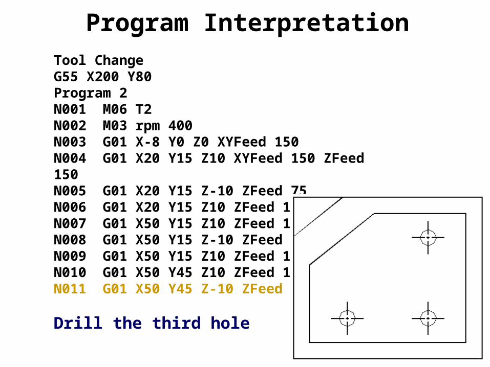
Program InterpretationTool ChangeG55 X200 Y80Program 2N001 M06 T2N002 M03 rpm 400N003 G01 X-8 Y0 Z0 XYFeed 150N004 G01 X20 Y15 Z10 XYFeed 150 ZFeed 150N005 G01 X20 Y15 Z-10 ZFeed 75N006 G01 X20 Y15 Z10 ZFeed 150N007 G01 X50 Y15 Z10 ZFeed 150N008 G01 X50 Y15 Z-10 ZFeed 75N009 G01 X50 Y15 Z10 ZFeed 150N010 G01 X50 Y45 Z10 ZFeed 150N011 G01 X50 Y45 Z-10 ZFeed 75
Drill the third hole

Program InterpretationTool ChangeG55 X200 Y80Program 2N001 M06 T2N002 M03 rpm 400N003 G01 X-8 Y0 Z0 XYFeed 150N004 G01 X20 Y15 Z10 XYFeed 150 ZFeed 150N005 G01 X20 Y15 Z-10 ZFeed 75N006 G01 X20 Y15 Z10 ZFeed 150N007 G01 X50 Y15 Z10 ZFeed 150N008 G01 X50 Y15 Z-10 ZFeed 75N009 G01 X50 Y15 Z10 ZFeed 150N010 G01 X50 Y45 Z10 ZFeed 150N011 G01 X50 Y45 Z-10 ZFeed 75N012 G01 X50 Y45 Z10 ZFeed 150
Retract to a position above the third hole

Program InterpretationTool ChangeG55 X200 Y80Program 2N001 M06 T2N002 M03 rpm 400N003 G01 X-8 Y0 Z0 XYFeed 150N004 G01 X20 Y15 Z10 XYFeed 150 ZFeed 150N005 G01 X20 Y15 Z-10 ZFeed 75N006 G01 X20 Y15 Z10 ZFeed 150N007 G01 X50 Y15 Z10 ZFeed 150N008 G01 X50 Y15 Z-10 ZFeed 75N009 G01 X50 Y15 Z10 ZFeed 150N010 G01 X50 Y45 Z10 ZFeed 150N011 G01 X50 Y45 Z-10 ZFeed 75N012 G01 X50 Y45 Z10 ZFeed 150N013 M05
Spindle off

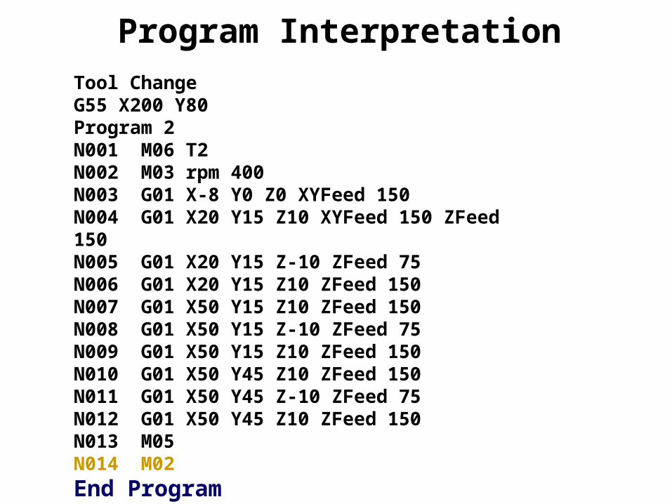
Program InterpretationTool ChangeG55 X200 Y80Program 2N001 M06 T2N002 M03 rpm 400N003 G01 X-8 Y0 Z0 XYFeed 150N004 G01 X20 Y15 Z10 XYFeed 150 ZFeed 150N005 G01 X20 Y15 Z-10 ZFeed 75N006 G01 X20 Y15 Z10 ZFeed 150N007 G01 X50 Y15 Z10 ZFeed 150N008 G01 X50 Y15 Z-10 ZFeed 75N009 G01 X50 Y15 Z10 ZFeed 150N010 G01 X50 Y45 Z10 ZFeed 150N011 G01 X50 Y45 Z-10 ZFeed 75N012 G01 X50 Y45 Z10 ZFeed 150N013 M05N014 M02
End Program