Stochastic modeling of atomizing spray in a complex swirl ...

© copyright FACULTY of ENGINEERING ‐ HUNEDOARA, ROMANIA 119
1. Fathollah OMMI, 2. Ehsan MOVAHEDNEJAD, 3. Kouros NEKOFAR
MANUFACTURING AND TESTING OF DOUBLE‐BASE SWIRL INJECTOR IN ORDER TO IMPROVE SPRAY CHARACTERISTICS
1. TARBIAT MODARES UNIVERSITY, TEHRAN, IRAN 2. ISLAMIC AZAD UNIVERSITY OF JOLFA, JOLFA, IRAN 3. ISLAMIC AZAD UNIVERSITY OF CHALOOS, CHALOOS, IRAN
ABSTRACT: A new design procedure for double‐base liquid injectors is proposed in this paper. The procedure is based on theoretical and experimental results. Then a computer code is developed and the performances of these injectors are studied for various conditions. Finally, four injectors are manufactured with high precision and then mounted on a test stand in order to investigate various important spray characteristics. A specialized laboratory was setup for the measurement of macroscopic spray characteristics under different pressure such as droplet distribution, spray angle, swirl effect. Through PDA cold test, the microscopic characteristics of injectors spray are also measured. KEYWORDS: Swirl Injector, Double–Base Injector, Macroscopic and Microscopic Characteristics, PDA Laboratory
INTRODUCTION As shown in figures 1 and 2, the double based liquid‐liquid injectors have many advantages making them applicable in aerospace industries. Fuel and oxidizer can be mixed more efficiently in such injectors, creating an ideal combustion condition and reducing the probability of combustion instability [1].
Figure 1: Double base– swirl injector
Figure 2: A Manufactured Injector
The swirl effect's advantages include producing micro‐diameter droplets and desirable spray angle which provide the perfect combustion condition. The rules used in the swirl injector theory are based on the principles of mass, angular momentum, energy conservation, maximum flow rate and minimum energy laws. Based on the design procedure, a computer code is developed, which performs the design and necessary calculations of different dimensions of injector. This program designs injector based on design data and calculates its dimensions. The necessary parameters for internal and external nozzles are fed into the program separately for obtaining their geometries. However, as mentioned, the radius of external nozzle should be more than the external radius of nozzle in the inner injector [2]. At the same time, the spray cone angle of inner injector should be more than outer injector, therefore both spray cones would contact to each other after discharging form injector. According to the design condition the internal nozzle must inject flow of 20 cc/sec in defined pressure of 10 bars. The external nozzle must also inject 120 cc/sec in 4 bars. The spray angles for the internal and external nozzles obtained 85° and 75° respectively. MANUFACTURING THE INJECTORS Four injectors are manufactured based on design calculations. The double‐based swirl injector has three parts including internal nozzle, external nozzle and lid [3]. Brass metal was chosen due to its special characteristics for accurate machining and minute drilling [4]. Detailed drawings of internal and external nozzle are shown in figures 3 and 4. These three parts are brazed and assembled precisely as shown in figure 5.

ACTA TECHNICA CORVINIENSIS – Bulletin of Engineering
2012. Fascicule 2 [April–June] 120
Figure 3: Manufacturing Diagram of the Internal Nozzle
Figure 4: Manufacturing Diagram External Nozzle
Figure 5: Assembled and disassembled
of a Manufactured Injector HYDRODYNAMIC TEST LABORATORY To check the quality of the manufactured injectors, a preliminary laboratory set‐up is needed. This set‐up will measure the macroscopic characteristics of injectors spray such as homogeneous spray distribution, spray angle and swirl effect on the spray formation under different pressure. This test rig was set up with the following parts as, Injector Stand, Pressurized Liquid Tanks, High Pressure Nitrogen Capsule, Manometer and Regulator, Radial and Sectional Collector, Stroboscope and High Speed Camera. The liquid emitted by the injectors are collected in two different collectors made of Plexy glass material as shown in figure 6 (a) and (b). The level of fluid in the radial and sectional collectors display spray distribution quality in r and θ direction respectively [5]. Sectional collector divided into six 60° section and the radial one divided into three co‐centric cylinders. Furthermore, a high speed camera is used to
capture the spray cone angle and atomized spray distribution of both internal and external nozzle [6].
Figure 6: (a) Radial and (b) Angular Collector
EXPERIMENTAL TEST RESULTS OF INJECTORS – FLOW–PRESSURE TEST This test is conducted to measure the flow changes under different working pressures for both internal and external nozzles. Figures 7 and 8 present the results of the experimental flow for a specific set of design conditions.
0
5
10
15
20
25
30
0 2 4 6 8 10 12 14 Figure 7: Flow rate of internal nozzle (cc/s)
versus pressure (bar)
020406080100120140160
0.5 1 1.5 2 3 4 5 6 7
Figure 8: Flow rate of external nozzle (cc/sec) versus pressure (bar)
SPRAY ANGLE TEST To show the spray formation of internal and external nozzle clearly a stroboscope and a high speed camera are used. Picture 9 displays the spray circulation of injector. As fluid pressure increases from 0 to 10 bar, the spray cone gradually opens to become fully developed as seen in figure 10. In figures 11 (a) and (b) the spray cone angle of both internal and external nozzle are approximately 70° and 80° respectively under design condition (Po=4 , Pf=10 bar) which are satisfactory in the light of theoretical calculations.
ACTA TECHNICA CORVINIENSIS – Bulletin of Engineering
2012. Fascicule 2 [April–June] 121
Figure 9: Spray Formation Stages with Regarding to Fluid Swirl
Figure 10: Fully Opened Spray Cone Under
design conditions (Pf=10, Po=4 bar)
Figure 11: Spray cone angle of (a) internal
and (b) External nozzle SPRAY DISTRIBUTION AND HOMOGENEITY TEST Sectional and radial collectors are used to check the symmetry of the fluid spray [7].
020406080100120140160180
1 2 3 4 5 6 Figure 12: Spray distribution of the injector
in each 60° section
0
100
200
300
400
500
600
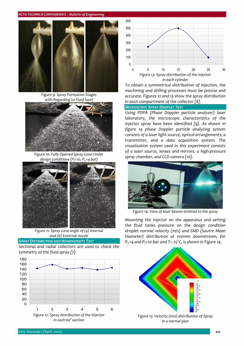
0 5 10 15 20 25 30 Figure 13: Spray distribution of the injector
in each cylinder To obtain a symmetrical distribution of injection, the machining and drilling processes must be precise and accurate. Figures 12 and 13 show the spray distribution in each compartment of the collector [8]. MICROSCOPIC SPRAY DROPLET TEST Using PDPA (Phase Doppler particle analyzer) laser laboratory, the microscopic characteristics of the injector spray have been identified [9]. As shown in figure 14 phase Doppler particle analyzing system consists of a laser light source, optical arrangements, a transmitter, and a data acquisition system. The visualization system used in this experiment consists of a laser source, lenses and mirrors, a high‐pressure spray chamber, and CCD camera [10].
Figure 14: View of laser beams emitted to the spray
Mounting the injector on the apparatus and setting the fluid tanks pressure on the design condition droplet normal velocity (m/s) and SMD (Sautre Mean Diameter) distribution at 100mm downstream, for Po=4 and Pf=10 bar and T= 250C, is shown in Figure 14.
Figure 15: Velocity (m/s) distribution of Spray
in a normal plan

ACTA TECHNICA CORVINIENSIS – Bulletin of Engineering
2012. Fascicule 2 [April–June] 122
Figure 16: SMD (Micron) distribution of injector spray
in a normal plan There is a high velocity zone around the injector axis that represents existence of the spray liquid sheet as it is seen in Figure 15. Droplets normal velocities are obtained in the range of 11 m/s. According the figure 16, droplets with less mean diameter are placed in center of the spray cone and the diameter increases along radius [11]. CONCLUSIONS The swirl double–base injector was designed with a new method. Then a computer code was developed to calculate the specific parameters of the injector. Based on these results, four injectors were manufactured precisely including internal nozzle, external nozzle and lead. To check the performance of these injectors, experimental tests were conducted. According to the figures 7–16 the injectors have excellent microscopic and microscopic spray characteristics such as spray angle, droplet distribution, Sautre Mean Diameter and droplet velocity. The results clearly show that the manufactured injectors produce flawless spray jets. REFERENCES [1.] Zahao Y.H., Hou M.H., Chin J.S., “Drop Size Distribution
from Swirl & Air‐blast Atomizer”, Atomization and Spray Technology, pp. 3–15, 1986.
[2.] Reitz R.D., Bracco F.V., “Mechanisms of Break–up of Round Liquid Jets”, Book Chapter the Encyclopaedia of Fluid Mechanics, N. Cheremisnoff, Gulf Publishing, Houston, Texas, Vol. 3, Chapter 10, pp. 233–249.
[3.] Ditiakin E.F., Koliachko L.F., Noikov B.V., Yagodkin V.E., “Fluids Spray”, Moscow, 1977.
[4.] Vasiliov A.P., Koderaftsov B.M., Korbatinkov B.D., Ablintsky A.M., Polyayov B.M., Palvian B.Y., “Principles of Theory and Calculations of Liquid Fuel Jet”, Moscow, 1993.
[5.] Ghafourian A., Mahalingam S., Dindi H., “A Review of Atomization in liquid Rocket Engines”, AIAA Paper 91‐0283.
[6.] Kargar A., “Optimized Arrangement Model of Injectors
in Injector Plate of a Liquid Propellant Rocket Engine Using PDA Cold Test Laboratory”, M.Eng. Thesis, Tarbiat Modares University, 2007.
[7.] Taylor D.H., Walsham B.E., “Combustion Processes in a Medium Diesel Engine”, Proc.Inst. Eng.Vol. 184, Part 3 J, pp. 67–76, 1970.
[8.] Tate R.W., “Spray Patternation”, Ind. Eng. Chem, Vol.52, No.10, pp. 49–52, 1960.
[9.] Ranganadha B.K., Vnarayanaswmy M., “Prediction of Mean Drop Size from Swirl Atomizer”, pp. 3–4, 99, the 2nd Int. Conference on Liquid Atomization and Spray System, June 1982.
[10.] Giffen E., Muraszew A., “The Atomization of Liquid Fuel”, Chapman & Hall, 1953.
[11.] Sutton G.P., “Rocket Propulsion Elements”, John Wiley & Sons 1986, 15th Edition
ACTA TECHNICA CORVINIENSIS – BULLETIN of ENGINEERING
ISSN: 2067‐3809 [CD‐Rom, online]
copyright © UNIVERSITY POLITEHNICA TIMISOARA,
FACULTY OF ENGINEERING HUNEDOARA, 5, REVOLUTIEI, 331128, HUNEDOARA, ROMANIA
http://acta.fih.upt.ro