Manuel UtilisationE motion · 27 340 pont de l'arche france tel. +(33) 02 32 98 91 32 fax: +(33) 02...
210
Operation manual
Transcript of Manuel UtilisationE motion · 27 340 pont de l'arche france tel. +(33) 02 32 98 91 32 fax: +(33) 02...

Operation manual

Dear Customer,
You have purchased an emotion edger and all the team at Briot International would like to thank you for this mark of your confidence.
The emotion edger is a laboratory machine designed for opticians and is used for carrying out operations such as creating and selecting jobs, centering and blocking spectacle lenses, edging and drilling lenses, drilling frames.
We advise you to read this manual carefully and keep it near the machine in order to be able to refer to it easily.
The information contained in this manual is not contractual and can be modified without prior notice. This document has been prepared with great care, but some unintentional errors or omissions may occur, although every effort has been made to avoid them. Briot International cannot, in any circumstances, be held responsible for any possible operating faults that might result from such errors or omissions.
BRIOT INTERNATIONAL DOES NOT GUARANTEE THE PERFORMANCE OF THE emotion IF THE INSTRUCTIONS CONTAINED IN THIS MANUAL ARE NOT OBSERVED.
2, rue Roger Bonnet27 340 PONT DE L'ARCHE
FRANCE
Tel. +(33) 02 32 98 91 32Fax: +(33) 02 35 02 02 94
www.briot.com
DEPENDING ON THE MACHINE VERSION AND OPTIONS AND ON THE DATE AND COUNTRY OF SALE, SOME EQUIPMENT ITEM(S)/FUNCTION(S) DESCRIBED IN THIS MANUAL MAY NOT BE INCLUDED IN YOUR MACHINE.


Θ GRAPHIC CODES
Different graphic codes have been used in this manual to allow the user to distinguish between different types of information and easily spot the items which demand special attention (e.g. safety-related items).
The table below lists all the codes and describes them:
TABLE 1: DESCRIPTION OF THE PICTOGRAMS
Graphic Code Description
Vital warning: Risk of human injury or material damage and machine malfunction. Follow the instructions carefully.
Vital recommendation: Risk of machine damage or malfunction.Follow the instructions carefully.
Vital preliminary actionBefore undertaking any action, check that the machine is disconnected.
Electrical hazard.
Heavy component.In particular, a second person is necessary to carry and move the machine.
Rotating component.In particular, do not put your hands near to the wheel unit.
Attaching component.In particular, beware of the clamping shafts closing.
Protective gloves must be worn.Especially for cleaning and changing the tanks.
Protective goggles must be worn.Especially for cleaning and changing the tanks.

Treatment of Waste Electrical and Electronic Equipment (applicable in the European Union and in European countries using a selective collection system)
This symbol affixed to the product or to its packaging indicates that the product wil l not be treated like household waste. Instead, it must delivered to the designated collection point where electric and electronic equipment may be recycled. By ensuring that this product is correctly disposed of, you wil l help prevent potentially harmful environmental and human consequences due to improper handling when improperly disposed of. The use of recovered materials preserves natural resources.For more information about where you can drop off this product for recycling, please contact your local waste disposal service or the shop where you purchased this product.
Overalls must be worn.Especially for cleaning and changing the tanks.
TABLE 1: DESCRIPTION OF THE PICTOGRAMS
Graphic Code Description

\\Table of contents
INSTALLATIONUnpacking the machine 1.13WarningProcedureRemoving the shipping rails 1.15Conditions
ProcedurePreparing the bench 1.17Machine dimensionsFloor space and drilling requiredWater connections 1.19Specifications
GeneralFiltration tank with pumpPump
Pipe connectionsFind the openings on the chassisProcedure
Electrical connections 1.23SpecificationsEdger wiring
ProcedureStarting the edger 1.25ProcedureSwitching the machine ON/OFFSAFETY PRECAUTIONSSafety 2.29OperatorMachineRecommendations 2.31USING YOUR EDGERPresentation 3.35Presentation of the machineDescription of the stations
Touch screenCentering/blocking systemScanform / DrillingEdger
Presentation of the application screenWork interfaceZone identificationReading sequenceVisual references
General principles of use 3.41Usual procedure : Job creation/selection
Calling/Creating a job/patternEntering the frame data or a pattern
Usual procedure : Digiform/DrillingModifying the shape of a patternPositioning the drilling holes
Usual procedure: Blocking/centering systemUsual procedure: Edging
Flow chartInserting / Removing the lensStarting / interrupting an edging cycleNormal edging cycle sequenceImportant notes
Application screen icons 3.51Job
Job screenDrilling / Digiform
Modifying the patternDrilling screen
Centering/blocking system
GeneralEdger
GeneralLens materialsTypes of lensesFinishingSub-finishing and associated parametersSafety-bevels
PolishingUsual procedure 3.59Job Creation/Selection
Calling up a job saved in the memorySaving a shape in the shape baseDeleting a shape/a job saved in the memory
DrillingProcedureFacts worth knowingHintsLimits
Blocking/centeringEdging
Producing a job with rimless finishingProducing a job with groove finishingProducing a job with bevel finishing
Special cases 3.73Modifying a shape - Digiform function
IntroductionProcedure
Applying an oversizeWhy?How?HintsImportant notesLimits
Edging the left lens with different parameters from those of the right lens
PrincipleProcedure
Edging several lenses identicallyPrincipleProcedure
Checking a finishing before the lens is edgedPrinciplePresentationVisualise a finishingPlacing a finishing manuallyProduce a manual bevelProduce a manual grooveFeel the lens again
Operating ranges: 3.87Points to rememberIllustration of finishing limits
Rimless FinishingBevel FinishingInclined Groove Finishing
DrillingConditionsLimits of hole positioningLimits related to the thickness of the lens
Limitation of the lens characteristics (blocker/pattern)Lens characteristics
CONFIGURATIONPresentation of configuration menus 4.95Presentation of the configuration menus access screen
Screen descriptionAccess / Exit
Presentation of the personalisation menus access

\\Table of contents
screenScreen descriptionAccess / Exit
Configuration of finishing parameters default values 4.97Presentation
PrincipleScreen descriptionAccess / Exit
General procedureSaving the new configurationLimits
BevelGrooveSafety-bevel
Adjustment of the setting values 4.103Preliminary remarksProcedureCorrection of frame and lens values 4.105Preliminary remarksProcedureConfiguration of general operating parameters 4.107Presentation
PrincipleScreen descriptionAccess / Exit
Configuration of the functionsSelecting the dialog languageActivating size compensation according to temperatureEnabling size compensation according to wheel conditionEnabling size compensation according to the bowing/flattening of the frame
Saving the new configurationConfiguration of Communication parameters 4.109Presentation
PrincipleScreen descriptionAccess / ExitEnabling / Disabling communication functions
MAINTENANCEPresentation of maintenance menus 5.113Presentation of the maintenance menus access screen
Screen descriptionAccess / Exit
Presentation of the maintenance screenScreen descriptionAccess / Exit
Visualising the components 5.115 Task list 5.117Maintenance of the touch screen unit 5.119Cleaning the touch screenMaintenance of the Scanform unit 5.121Cleaning the ScanformReplacing a stylus tipReplacing the frame clip tubesReplacing the centering plateMaintenance of the centering/blocking system zone 5.125Cleaning the ground glass screenCleaning the lower lens of the collimatorReplacing the main fuse
Regular maintenance of the edger 5.127Replacing the flexible lens clamp adaptor pad
Preliminary remarksProcedure
Replacing the mill bitPreliminary remarksProcedureHints
Replacing the lens feeler tipsPreliminary remarksProcedureHints
Dressing a wheelPreliminary remarksProcedureHints
Cleaning / replacing the removable visorPreliminary remarksReplacing the visorHints
Cleaning the filters and water tankPreliminary remarksProceduresHints
Emptying the water tankPreliminary remarksProcedureHints
Handling the covers 5.147Removing the covers
When?How?
Replacing the coversPreventive maintenance 5.149HintsReplacement table for standard parts Adjustments 5.151 Presentation of the settings menus access screen
Screen description Access / Exit
Adjusting the Scanform Adjusting the feeling
When? Procedure Hints
Adjusting the sizes When? Procedure
Adjusting the flush of the mill bit When? Procedure Hints
Adjusting the touch screen When? Procedure Hints
Consulting the setting values Presentation Access/Exit/Navigation Presentation of the setting value screens
Consulting the statistics 5.169 Presentation of the statistics menu
Screen description Access/Exit
Consultation principles Incident log General operation of the machine

\\Table of contents
Messages 5.185Types of messagesList of messages.TESTSPresentation of test menus 6.197Presentation of the test menus access screen
Screen descriptionAccess / Exit
Typical test screenOperating principle 6.199Operating principle of a typical screen
Tests involvedProcedureTest sequence
Operation of the other screensScreen with switchScreen with micro-switches and photocells
TECHNICAL SPECIFICATIONSCharacteristics 7.213Technical specifications 7.214CharacteristicsEC Standards:

\\Table of contents

REVISION FOLLOW-UPRevision 01
Page New/Modified Item
New document

. . .
3-10

1 INSTALLATION

1-12
UNPACKING THE MACHINE
#1&2 #3&4
#5
#8&9
Keep the case, the small carton and the hose near the machine.
#6&7

1-13
=> Installation
1.1 UNPACKING THE MACHINE1.1.1 WARNING
> Ensure that the machine is placed in accordance with the TOP and BOTTOM signs on the box. > Place the machine on a flat and stable surface.
1.1.2 PROCEDURE
Follow the steps below to unpack the machine:
Flow chart 1-1: Unpacking the edger
#1 Place the machine on the floor in its packing with the help of another person.
#2 Cut the two straps on the main packaging carton.
#3 Cut the adhesive tapes on the main packaging carton.
#4 Check that the accessories (small box, case and tube) have been supplied and keep them close to the machine.
#5 Pull the main packaging carton upwards and remove it.
#6 Cut the two straps on the second packaging carton.
#7 Cut the adhesive tape on the second carton.
#8 Pull the second packaging carton upwards and remove it.
#9 Remove the plastic protection from the machine.
#10 With the help of a second person, lift the machine by the rails and place it on the work bench.
#11 Keep the packaging cartons. We advise you to stock them flat.

Installation...Unpacking the machine
1-14

1-15
=> Installation
1.2 REMOVING THE SHIPPING RAILS1.2.1 CONDITIONS
> The machine is placed on the work bench. > There is enough space around the machine.
1.2.1.1 PROCEDURE
To remove the shipping rails, follow the procedure below:
Flow chart 1-2: Removing the shipping rails
→ As shown...
Illustration 1-1: Removing the fixing screws from the shipping rails
#1 With the help of a second person, tip the machine gently to the rear so as to have access to the 4 rail fixing screws.
#2 With a 13 mm Allen key, take out the 4 fixing screws and remove the rails.
#3 Keep the shipping rails with the rest of the packaging cartons.
#1

Installation...Removing the shipping rai ls
1-16

1-17
=> Installation
1.3 PREPARING THE BENCH1.3.1 MACHINE DIMENSIONS
The following illustrations show the machine dimensions.
Flow chart 1-3: Edger dimensions
→ Height = 442 mm → Width = 728 mm → Depth = 600 mm → Weight = 75 kg
H =
442
mm
W = 728 mm
D = 600 mm

Installation...Preparing the bench
1-18
1.3.2 FLOOR SPACE AND DRILLING REQUIRED
Θ ILLUSTRATION
The following sketch shows the positioning of the machine on the bench and the openings which must be provided. Position your machine correctly before drilling the bench!
Illustration 1-2: Positioning the machine on the bench and drilling to be made
Θ RECOMMENDATIONS
Follow the dimensions given. Leave enough space around the edger. Ensure that the bench is stable and level. Install the edger away from any source of heat.
Discharge

1-19
=> Installation
1.4 WATER CONNECTIONS1.4.1 SPECIFICATIONS
1.4.1.1 GENERAL
> Water intake with a stop-valve fitted with a 20 x 27 mm female connector and a filter seal.
This stop-valve must be reserved for the machine and placed at a maximum of 80 cm from the place provided for the machine.
The stop-valve must be easy to reach and closed when not in use. > Water pressure = 4 - 7 bars > Water discharge through a 100 mm diameter pipe.
The slope must be at least 5% to ensure proper evacuation of the refuse.
1.4.1.2 FILTRATION TANK WITH PUMP
> W 600 x H 400 x D 315 mm > 60-liter capacity > Three levels of filtration
1.4.1.3 PUMP
> W 400 x H 230 x D 300 mm > Power = 450 W max. > Q = 20/220 l/min > V = 220 - 240 V > H = 8 - 1 m > F = 50 Hz > IP = 68
1.4.2 PIPE CONNECTIONS
1.4.2.1 FIND THE OPENINGS ON THE CHASSIS
Illustration 1-3: Chassis openings
Discharge
Water supply

Installation...Water connect ions
1-20
1.4.2.2 PROCEDURE
→ As shown...
=> Level!
#1 #3
#2
#4
#6
#7
Settling tank
#4#6
Filtration tank
=> DIRECT WATER SUPPLY => CLOSED CIRCUIT
#5
Pump power connector

Installation...Water connections
1-21
→ Flow chart
To connect the water supply to the edger and fit the pipes, follow the procedure below:
Flow chart 1-4: Pipe connections
#1 Check that the machine is switched off: On/Off switch OFF and mains plug disconnected.
#2 Check that the water supply is closed.
#3 Ensure that the machine is level => screw or unscrew the four feet.
#4 Connect the water drain pipe to the chassis.
#5 Fit the filter seal between the water supply connection and the valve if you operate in direct water supply.
#6 Connect the water supply pipe to the valve (if direct water) or to the pump (in closed circuit).
#7 Connect the used water discharge pipe if you operate in direct water supply.
#8 When the water circuit is being filled, check the watertightness of the unit, especially around the solenoid valves.
#9 If operating in closed circuit, connect the pump supply to the pump power connector.

Installation...Water connect ions
1-22
1-23
=> Installation
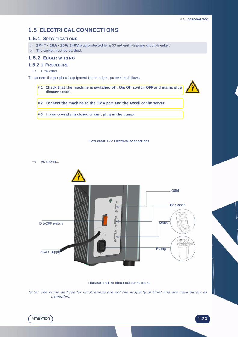
1.5 ELECTRICAL CONNECTIONS1.5.1 SPECIFICATIONS
> 2P+T - 16A - 200/240V plug protected by a 30 mA earth-leakage circuit-breaker. > The socket must be earthed.
1.5.2 EDGER WIRING
1.5.2.1 PROCEDURE
→ Flow chart
To connect the peripheral equipment to the edger, proceed as follows:
Flow chart 1-5: Electrical connections
→ As shown...
Illustration 1-4: Electrical connections
Note: The pump and reader i l lustrat ions are not the property of Br iot and are used purely as examples.
OMA
PumpPower supply
ON/OFF switch
Bar code
GSM
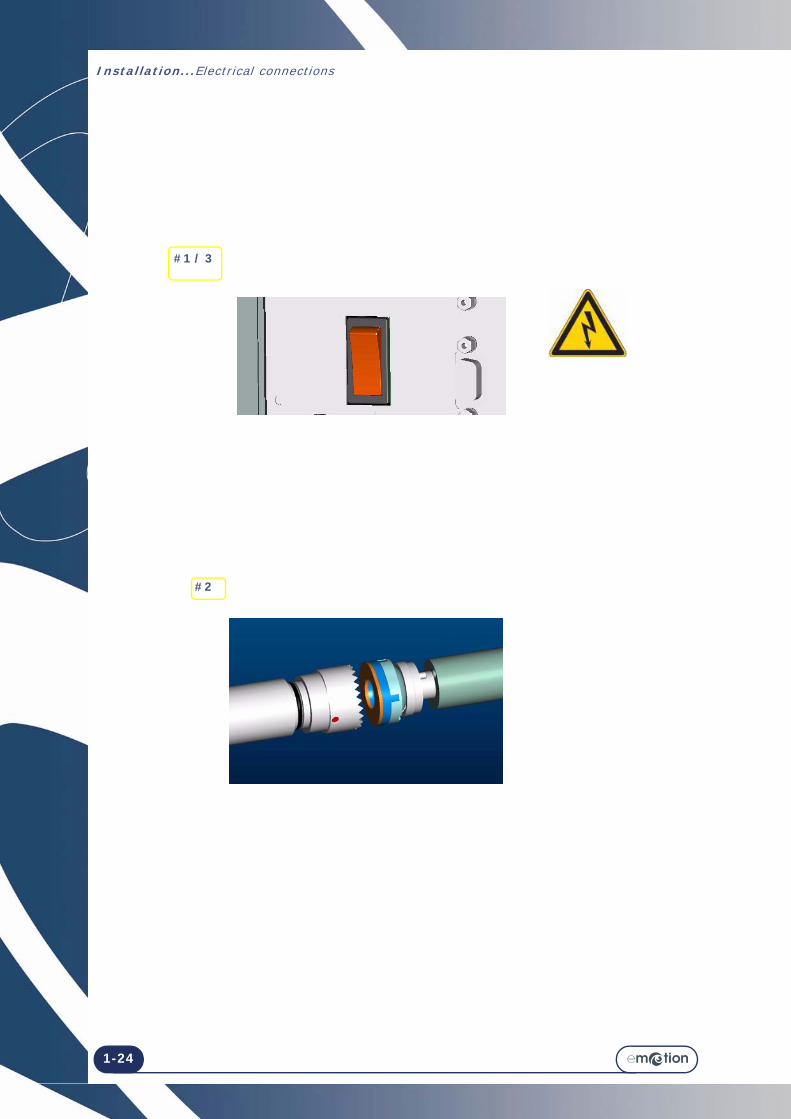
#1 Check that the machine is switched off: On/Off switch OFF and mains plug disconnected.
#2 Connect the machine to the OMA port and the Axcell or the server.
#3 If you operate in closed circuit, plug in the pump.
Installation...Electr ical connect ions
1-24
#1 / 3
#2

1-25
=> Installation
1.6 STARTING THE EDGER1.6.1 PROCEDURE
→ Flow chart
To start the edger proceed as follows:
Flow chart 1-6: Starting the edger → As shown...
Illustration 1-5: Starting the edger
#1 Check that the machine is switched off: On/Off switch OFF and mains plug disconnected.
#2 Fit the lens clamping and lens holder adaptors on the shafts.
#3 Plug in the machine and switch on (On/Off switch lit).
#4 Start a dummy cycle and adjust the flow of the visor and edging chamber sprays using the flow adjusting screws located on the left side of the machine (use a key).
#5 Carry out one or two jobs to check that the machine operates correctly.
Adjust the flow!

1-26
Installation...Start ing the edger
1.6.2 SWITCHING THE MACHINE ON/OFF
Flow chart 1-7: Switching the machine ON/OFF
ON position«1» pushed in - Lit up
OFF position«0» pushed in - Unlit

2 SAFETY PRECAUTIONS

2-28

2-29
=> Safety precautions
2.1 SAFETY2.1.1 OPERATOR
> Read the instructions carefully and always keep the manual near your machine so you can refer to it easily.
> This is a rotary machine: the wheels are potentially dangerous. Be very careful and keep your hands away from the set of wheels.
> Two people are necessary to move the machine. > When you activate the clamp shafts, keep your fingers outside the contact areas. > Before touching the fuses, disconnect the mains cable. > Make sure that the installation is perfectly water-tight. > Before servicing the edger, check that the mains cable is unplugged.
2.1.2 MACHINE
> Make sure your voltage source corresponds to the voltage specified on the identification plate located at the rear of the machine. If you are unsure of the type of current available in your premises, contact your electricity company.
> If the machine is not going to be used for a long period of time, disconnect the power cords from the wall outlet.
> Disconnect the machine if there is an electrical storm or when the machine is left unattended for a long period.
> Keep the machine away from any source of heat. A radiator is a heat source which can be detrimental to the correct operation of the machine.
> The openings in the cover are designed to ventilate the machine and contribute to its normal operation. Do not obstruct them or cover them.
> Make sure that the machine is installed in a correctly ventilated room. > Do not overload the wall sockets or plugs because you would increase the risk of fire or electric shock. > Avoid using electric extension leads. > Keep the machine away from any source of dust. > Any servicing or work on the machine (with the cover open or closed) must be undertaken by a Briot
technician.
THE MANUFACTURER CANNOT BE HELD RESPONSIBLE FOR DAMAGE CAUSED BY ANY USE OF THE MACHINE WHICH DOES NOT OBEY THE INSTRUCTIONS IN THIS MANUAL OR THOSE DISPLAYED ON THE MACHINE ITSELF.

Safety precautions...Safety
2-30

2-31
=> Safety precautions
2.2 RECOMMENDATIONS > Comply with the machine maintenance messages. > Protect the machine's power cords. > Contact a Briot technician for all repairs and always order Briot spare parts. > Use only products delivered and specified by Briot. > The machine is guaranteed to function correctly if the procedures stipulated in this manual are complied with. > Ensure that the edger is cleaned regularly. Clean the outer cover with a clean, soft cloth moistened with a little alcohol. CAUTION: Do not use the following products for cleaning: Products containing ammonia, soda or acetic acid Organic products such as acetone, benzene or trichlorethylene.
> Touch screen: Do not press too hard on the touch screen or you could break it. Do not press the screen with sharp objects such as a pens, scissors, pliers, etc. Make sure your fingers are dry when touching the screen. If the reaction zone does not correspond to the key location, adjust the touch screen in relation to the display
(see paragraph Adjusting the touch screen , Chapter Settings & adjustments) . Clean the touch screen with a soft, clean, dry cloth.
> Scanform zone: To ensure an optimum working life of the equipment and performance of the shapes and sizes: → Close the lugs of the frame eyewires. → Clean the frame in the ultrasonic bath before entering the data. In the event of a data entry problem, push the emergency stop button and wait until the Scanform returns
control to you before resuming the operations.
> Centering/locking system zone: Do not scratch or put your fingers on the optical components of the blocking system (collimator lens, ground
glass screen) or you may permanently alter the measurements of the equipment. Ensure the lens you have inserted is clean. Before blocking the lens, always check which type of block is required and ensure that the lens blocking and
lens holder adaptors are appropriate for the job to be done. Use blocks designed and supplied by Briot. Use new adhesives. Lay the lens down on the three lens holder pins, so that it is stable. Dot single vision lenses at their optical center using a frontofocometer. Highlight the marking with a fine
felt-tip pen No. 24 06 211. Deblocking a lens. → Even though the deblocking system is easy to use, follow the procedure described below to avoid the risk
of damaging the lens. Change the blocks regularly. Their lifespan is 100 blocking operations.
> Edging zone: Before starting the machine, check that the water supply is working (valve open). Make sure that the installation is perfectly water-tight. Change the water in the tank regularly if your machine operates in closed water circuit mode. Make regular checks of the condition of the feeler tips and change them if they are worn, chipped or
damaged. Remove glass and CR39 dust daily using clean water and a soft sponge or a brush so as not to scratch the
plastic surfaces. Clean the visor regularly.

2-32
Safety precautions...Recommendations

3 USING YOUR EDGER

3-34

3-35
=> Using your Edger
3.1 PRESENTATION 3.1.1 PRESENTATION OF THE MACHINE
Θ GENERAL ILLUSTRATION
The illustration below (Illustration 3-1) is an overall view of the machine.
Illustration 3-1: Overall view of the edger
Θ MAIN PARTS
The exploded view below (Illustration 3-2) shows the main parts of the edger.
Illustration 3-2: Exploded view of the edger
Touch screen
Centering/blocking system
Edging chamber
Scanform / Digiform
Edging chamber
Electronic system
Carriage
Scanform / Digiform
Safety-Bevel Grooving Drilling System
Centering/blocking system
Screen

Using your Edger...Presentat ion
3-36
3.1.2 DESCRIPTION OF THE STATIONS
The emotion is composed of the following stations:3.1.2.1 TOUCH SCREEN
The touch screen allows you to: > Use the emotion > Enter the job data > Display the shape of the frame and the lens > Display the drilling holes > Enter the edging data.3.1.2.2 CENTERING/BLOCKING SYSTEM
The blocking system allows you to: > Block the lens automatic or manually.The centering system allows you to: > Automatically recognise a pattern or a demonstration lens > Recognise the drilling plan of a job > Manually center the dotted, bifocal and progressive lenses.3.1.2.3 SCANFORM / DRILLING
The Scanform allows you to: > Enter the characteristics of the frame, shape and gaps > Enter the position of the frame groove for a better adaptation of the lens in the frame eyewire. > Enter the data for one eye or both > Enter the shape of a pattern or a demonstration lens (automatic detection of either of them)The drilling function allows you to: > Drill holes in the frame for attachment of the lenses > Modify the shape of a frame to adapt it to a specific lens shape.3.1.2.4 EDGER
The edger allows you to:Edge the lens according to the frame, material shape and power from the shape data entered.

Using your Edger...Presentation
3-37
3.1.3 PRESENTATION OF THE APPLICATION SCREEN
3.1.3.1 WORK INTERFACE
The screen below (Screen 3-1) is displayed after initialising the equipment at start-up.
Screen 3-1: Application screen3.1.3.2 ZONE IDENTIFICATION The application screen below (Screen 3-2) can be divided into zones.
Screen 3-2: Identification of the application screen zones
Tabs: Job/Scanform
Job No.
Tabs: Drilling / Digiform
Tabs: Centering/blocking system
Tabs: Edging
Tab-related function

Using your Edger...Presentat ion
3-38
3.1.3.3 READING SEQUENCE
The screen is organised so that you can follow the steps in logical order.The interface includes 4 tabs giving access to the preparation/production steps of the spectacles. 1 Job Creation (Scanform) /Selection 2 Digiform/Drilling 3 Centering/blocking system 4 Edging operationThe parameters for each operation are defined in each of the related tabs.For a more detailed description of the use of the equipment, see “General principles of use”, page 41.
Screen 3-3: Reading sequence of the application screen
Note: The numbers and arrows show the sequence of the procedure for general use.
1. 2. 3. 4.

Using your Edger...Presentation
3-39
3.1.3.4 VISUAL REFERENCES
3.1.3.4.1 TYPES OF BUTTONS
There are different types of buttons corresponding to the different types of action or information to be entered :
Θ IN ALL OF THE MENUS
> The action button: Produces an immediate action or is used to make a selection in a pull-down list.Example:
> The entry button: Used to enter a value using the numeric keypad and to display it.Example:
Θ IN THE TECHNICAL MENUS
> The selection button: Used to select a function.
3.1.3.4.2 ACCESSIBILITY OF FUNCTIONS
The accessible menus or functions also follow distinct graphic codes.
> The buttons or menus which can be enabled are highlighted, those which cannot be enabled are grayed.Example: Can be enabled Cannot be enabled
SEVERAL POSSIBLE SELECTIONSYou can enable one or more functions.
ONE POSSIBLE SELECTION ONLYYou can enable one function only.
The function is not selected. The function is not selected.
The function is selected and enabled.
Example: The type of percent bevel will be displayed in the Bevel sub-finishing menu of the main application screen.You can select all or part of the bevel types.
The function is selected and enabled exclusively.
Example: When the Bevel finishing type is selected in the personalisation menu, it will be displayed by default on the Finishing button of the main application screen.One finishing type only can be displayed by default.

3-40

3-41
=> Using your Edger
3.2 GENERAL PRINCIPLES OF USEThe standard procedure is carried out by using the different tabs successively.3.2.1 USUAL PROCEDURE : JOB CREATION/SELECTION
Enable the JOB tab
3.2.1.1 CALLING/CREATING A JOB/PATTERN
Calling an existing pattern from the data base:
Calling an existing job from the data base:
Creating a new profile:
Calling a job from the server data base:
Proceed as follows:
> Select the icon corresponding to the desired action.
> Then long press this button to select the job/pattern or define the number associated with the creation of your pattern.
When the numeric key pad is displayed, enter the job number and confirm it.Result: The shape requested is displayed on the screen. The job number is displayed on the top left
of the display zone. The display is modified according to the job characteristics and the default configuration values.
Note: Loading a job causes the lens mater ia l data, f in ishing data, etc. to be specif ied.. . automatical ly.
Note: Upon each creat ion step, the pattern is saved automatical ly in the data base.
Using your Edger...General pr inciples of use
3-42
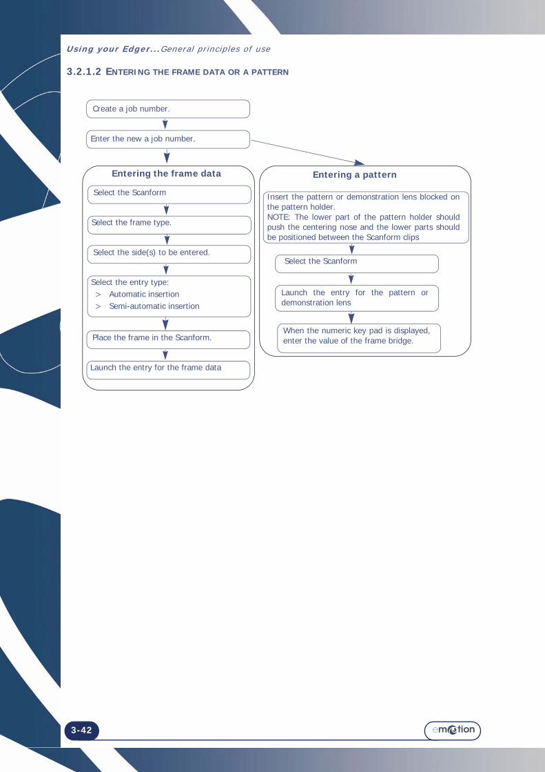
3.2.1.2 ENTERING THE FRAME DATA OR A PATTERN
Create a job number.
Enter the new a job number.
Select the Scanform
Select the frame type.
Insert the pattern or demonstration lens blocked on the pattern holder.NOTE: The lower part of the pattern holder should push the centering nose and the lower parts should be positioned between the Scanform clips
Select the ScanformSelect the side(s) to be entered.
Select the entry type: > Automatic insertion > Semi-automatic insertion
Place the frame in the Scanform.
Launch the entry for the frame data
Launch the entry for the pattern or demonstration lens
When the numeric key pad is displayed, enter the value of the frame bridge.
Entering the frame data Entering a pattern

Using your Edger...General principles of use
3-43
3.2.2 USUAL PROCEDURE : DIGIFORM/DRILLING
Enter the Drilling tab .
3.2.2.1 MODIFYING THE SHAPE OF A PATTERN
To modify the shape of a pattern, use the functions on the bottom of the screen.
3.2.2.2 POSITIONING THE DRILLING HOLES
To get access to the drilling menu, use this key:
> Add a hole using this key: > Select the coordinate to be modified (X, Y, Dia.) using the navigation keys.
> Enter the desired value using this button: or increment/decrement the value using these keys: and

Using your Edger...General pr inciples of use
3-44
Pin
#1 #2
#3
#5
Blocker head
Blocker arm
#4

Using your Edger...General principles of use
3-45
3.2.3 USUAL PROCEDURE: BLOCKING/CENTERING SYSTEM
Enter the blocking/centering tab.
Select the side to be blocked.
Place a lens holder, corresponding to the lens to be blocked, on the ground glass screen.
Place the lens to be blocked on its holder.
Select the blocker type.
Center the lens
Place a pin in the blocker head
Rotate the blocker head by 180°.
Rotate the blocker arm
Lower the blocker head on the lens.
#1
#2
#3
#4
#5

Using your Edger...General pr inciples of use
3-46
3.2.4 USUAL PROCEDURE: EDGING
Enter the Edging tab .

3-47
=> Using your Edger
3.2.4.1 FLOW CHART
The following flow chart shows the usual edging procedure.
> To obtain more information about a step or to see the relevant icons, click on the zone concerned.
Flow chart 3-1: Usual procedure
Call a job number.
Select the lens material.
Select the type of lens.
Select the finishing type.
Select the sub-finishing type.
Select the type of front safety-bevel, if desired.
Select polishing, if desired.
Place the lens in the edging chamber.
Start the edging process.
Select the type of rear safety-bevel, if desired.
At the end of the cycle, open the lens camp shaft.
Remove the edged lens carefully.
Using your Edger...General pr inciples of use
3-48
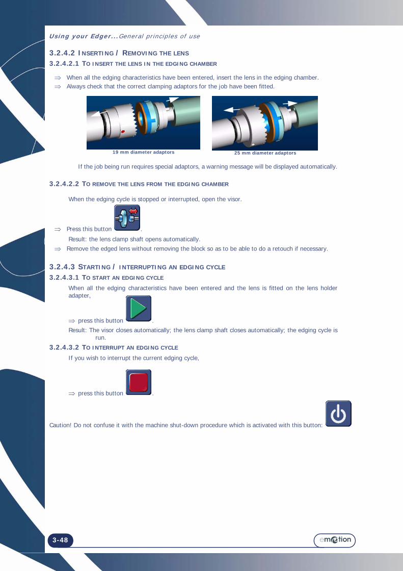
3.2.4.2 INSERTING / REMOVING THE LENS 3.2.4.2.1 TO INSERT THE LENS IN THE EDGING CHAMBER
When all the edging characteristics have been entered, insert the lens in the edging chamber. Always check that the correct clamping adaptors for the job have been fitted.
If the job being run requires special adaptors, a warning message will be displayed automatically.
3.2.4.2.2 TO REMOVE THE LENS FROM THE EDGING CHAMBER
When the edging cycle is stopped or interrupted, open the visor.
Press this button .
Result: the lens clamp shaft opens automatically. Remove the edged lens without removing the block so as to be able to do a retouch if necessary.
3.2.4.3 STARTING / INTERRUPTING AN EDGING CYCLE
3.2.4.3.1 TO START AN EDGING CYCLE
When all the edging characteristics have been entered and the lens is fitted on the lens holder adapter,
press this button .Result: The visor closes automatically; the lens clamp shaft closes automatically; the edging cycle is
run.
3.2.4.3.2 TO INTERRUPT AN EDGING CYCLE
If you wish to interrupt the current edging cycle,
press this button .
Caution! Do not confuse it with the machine shut-down procedure which is activated with this button:
19 mm diameter adaptors 25 mm diameter adaptors

Using your Edger...General principles of use
3-49
3.2.4.4 NORMAL EDGING CYCLE SEQUENCE
Once you have started the edging cycle, the following steps follow automatically:
Flow chart 3-2: Edging cycle sequenceNote: Select ing Manual f in ishing (bevel ing, grooving) leads to a modif icat ion in the standard
edging cycle sequence.
3.2.4.5 IMPORTANT NOTES
3.2.4.5.1 WHEN JOB DATA ARE RECEIVED
> If the job provides the edging data, they are displayed automatically.Example: If the job finishing is a bevel, the finishing displayed will automatically be Bevel.
> If the job provides no edging data, the characteristics configured by default (see Configuration of finishing parameters default values, chapter 4) are displayed automatically.
Example: If the default finishing is Bevel and the type is Auto, the displayed finishing will be Bevel and the sub-finishing will be Bevel Auto.
> If the job specifies data which have been excluded from the edger configuration, an « Incompatible edger configuration » message is displayed (see , chapter 5).
> If you modify the job data before starting to edge one of the lenses, the new characteristics will be memorised automatically and applied to the two lenses.
Caution! Check the parameter values of the two lenses. > The lens characteristics (material and type) determine the types of finishing available.
Example: A mineral lens cannot be drilled. Drilling finishing is therefore not available in the finishings pull-down menu when Mineral lens material is selected.
3.2.4.5.2 DURING EDGING OF THE SECOND LENS
Always check that the preselected type of finishing is the finishing that you wish to apply.
In fact, the finishing selected for the first lens is automatically memorised and preselected for the following lens (see “Edging several lenses identically”, page 77 and see “Edging the left lens with different parameters from those of the right lens”, page 76).
Check the parameter values.
emotion
Automatic closing of the lens clamp shaft
Lens roughing
Lens finishing (Rimless or Bevel)
Lens chamfering (if selected)
Lens polishing (if selected)
Lens safety-beveling (if selected)
Lens grooving (if selected)
Lens drilling (if selected)

Using your Edger...General pr inciples of use
3-50

Using your Edger...Application screen icons
3-51
3.3 APPLICATION SCREEN ICONS The screens and tables below present and describe all the icons of the user interface classified in type or menu order.3.3.1 JOB
Screen 3-4: Job screen icons3.3.1.1 JOB SCREEN
Short press: The pattern base is displayed.Long press: The internal shapes base is displayed.
Short press: The calculator is displayed for you to enter a job No. saved in the internal memory.Long press: The jobs base is displayed.
Short press: The job is sent to an OMA server. Short press:
Scanform entry is launched.
Select frame type
Select side to be entered
Select entrytype(Auto, semi-auto)
Center distance between lenses
Access to Scanform screen
Short press: The calculator is displayed to enter a job No. to be loaded from the OMA. When the calculator is displayed, a bar code can be entered.
Previouspage
Move up
Move down
Nextpage
Numeric entry
ConfirmCancel the job
Return to Digiform screen

Using your Edger...Appl icat ion screen icons
3-52
3.3.2 DRILLING / DIGIFORM
3.3.2.1 MODIFYING THE PATTERN
Screen 3-5: Pattern modification screen icons3.3.2.2 DRILLING SCREEN
Screen 3-6: Drilling Sub-Finishing Icons
Note: Dri l l ing angle set to 10°
Width Height W/H ratio
H/W ratio
PerimeterHalf-height
Oversize thickness
Access to drilling screen
Navigation arrow in the table
Return to Digiform screen
Drill an elongated hole
Add a hole
Increment
Decrement
Numeric entry
Remove a hole
Confirm

Using your Edger...Application screen icons
3-53
3.3.3 CENTERING/BLOCKING SYSTEM
3.3.3.1 GENERAL
Screen 3-7: Blocking screen icons
Left pupillary height
Left half-pupillary distance
Bridge
Right pupillary height
Right half-pupillary distance
Save in the pattern base
Horizontal offset
Vertical offset

Using your Edger...Appl icat ion screen icons
3-54
3.3.4 EDGER
3.3.4.1 GENERAL
Screen 3-8: Edging tab general icons.
3.3.4.2 LENS MATERIALS
Note: The presence and order of the icons displayed on the screen depend on the job data (see “When job data are received”, page 49).
Screen 3-9: Lens Material Icons
Oversize to boxing width
Lens selection
Lens materials
Finishing
Sub-Finishing
Launch the edging process
Rear safety-bevels
Front safety-bevels
PolishingTypes of lensesTighten the lens
Trivex™
Polycarbonate
CR39
Mineral
High Index Plastic

Using your Edger...Application screen icons
3-55
3.3.4.3 TYPES OF LENSES
Note: The presence and order of the icons displayed on the screen depend on the job data (see “When job data are received”, page 49).
Screen 3-10: Lens Type Icons
> Hydrophobic
Specific cycle suitable for lenses with hydrophobic treatment. > Fragile
Specific cycle suitable for lenses that you consider to be fragile: the roughing phase is slower than during a normal cycle.
> Normal
Cycle suitable for the majority of lenses.NOTE: If the lens type is HI and hydrophobic or fragile, roughing will be carried out using the mineral
roughing wheel to remove the risk of chipping the lens.
3.3.4.4 FINISHING
Note: The presence and order of the icons displayed on the screen depend on the job data (see see “When job data are received”, page 49).
Screen 3-11: Finishing Type Icons
Hydrophobic Fragile Normal
Rimless
Grooving
Bevel

Using your Edger...Appl icat ion screen icons
3-56
3.3.4.5 SUB-FINISHING AND ASSOCIATED PARAMETERS
> The following screen is a montage to show all possible sub-finishing.
Screen 3-12: Sub-finishing type icons
> Groove/Manual Bevel By selecting this type of finish, you can check and reposition the bevel/the groove during the edging cycle using a special screen which is displayed after the second lens feeling cycle.
.
> Groove/Automatic Bevel The apex of the bevel or groove is automatically positioned at 1/3 of the lens thickness from the front face.
> Groove/33% Bevel The apex of the bevel is positioned at 33% of the lens thickness from the front face.
> Groove/50% Bevel The apex of the bevel is positioned at 33% of the lens thickness from the front face.
> Groove/Front Face Bevel The bevel follows the front face of the lens and is positioned at a given distance in mm between the apex of the bevel and the front face of the lens.
> Groove/Rear Face Bevel The bevel follows the rear face of the lens and is positioned at a given distance in mm between the apex of the bevel and the front face of the lens.
IMPORTANT NOTE
> If the maximum thickness of the lens is less than 2 mm, the applied bevel or groove will automatically be of 1/2 - 1/2 type, whichever type of bevel/groove is selected initially.
More information about limits: Click here or see see “Operating ranges:”, page 87.
GROOVE
or
BEVEL
Manual
Auto
33%
50%
Front face
Rear face

Using your Edger...Application screen icons
3-57
3.3.4.6 SAFETY-BEVELS
Screen 3-13: Safety-Bevel Type icons
IMPORTANT NOTES
> A safety-bevel can only be made when:
- The distance between the apex of the bevel and the front/rear face of the lens is greater than 1.6 mm.
- The distance between the front edge of the groove and the front face of the lens is greater than 0.4 mm, and the distance between the rear edge of the groove and the rear face of the lens is greater than 0.4 mm. (Depth of safety-bevel = 0.2 mm).
> If you make a retouch whose value is greater than 0.20 mm, the lens will be retouched but the safety-bevel(s) will be machined or even removed.
More information about limits: Click here or see see “Operating ranges:”, page 87.
Front face 0.2mm
No front face safety-bevel
Rear face 0.2mm
Rear face 0.4mm
Rear face 0.6mm
No rear face safety-bevel

Using your Edger...Appl icat ion screen icons
3-58
3.3.5 POLISHING
Note: The presence and order of the icons displayed on the screen depend on the job data (see “When job data are received”, page 49).
Screen 3-14: Polishing Icons
WITHOUT WITH

Using your Edger...Usual procedure
3-59
3.4 USUAL PROCEDURETo familiarize you with the emotion interface and its general operation, we suggest that you carry out the following jobs. Job Creation/Selection.3.4.1 JOB CREATION/SELECTION
3.4.1.1 CALLING UP A JOB SAVED IN THE MEMORY
The numbers of this illustration refer to the step numbers below.
Follow the steps below to call up a job saved in the memory:
3.4.1.2 SAVING A SHAPE IN THE SHAPE BASE
The machined shapes are saved automatically in the equipment data base.
3.4.1.3 DELETING A SHAPE/A JOB SAVED IN THE MEMORY
To delete a job from a job menu that can be accessed via use this button
#1
#2
#3
1 A short press on the job selection key ( ) opens the numeric key pad and a long press displays the complete list of jobs in the memory. 2 Go to the desired job using the following keys: , . Enter the job number to be called up.
3 Confirm your choice when quitting the list of jobs in the memory: .Press the key to confirm.
4 The chosen shape and the customer's parameters are displayed in the screen.
5 The jobs are saved automatically when a new job is created or called up. They are deleted after they have been edged.

Using your Edger...Usual procedure
3-60
PRODUCING A JOB WITH DRILLING
Illustration 3-3: Example of the production of a job with Drilling
Navigation arrow in the table
Add a hole
Increment
Confirm
Decrement
Numeric entry
Drill an elongated hole
Delete a hole

Using your Edger...Usual procedure
3-61
3.4.2 DRILLING
3.4.2.1 PROCEDURE
Remarks • The current hole is shown by a red cross.• The previously selected hole is shown by pink circle.• To position a hole from the edge of the lens, your entered value should be within [-2,5 mm, +15 mm]. • To position a hole measured with reference to another hole, your entered value should be within
[-15 mm, +15 mm]. • Elongated holes are defined between the currently edited point and the previous point.3.4.2.2 FACTS WORTH KNOWING
> Drilling, if it is selected, is the last step in the edging process. > If you do not want holes, ensure that no hole has been entered in the drilling tab. > Elongated holes and notches are always machined from the edge of the lens towards the centre. > Characteristics of the diameter of a hole: → The diameter of a drilled hole is always greater or equal to that of the mill bit which is fitted.
→ Special case: If the diameter of the fitted bit is greater than the diameter of the hole and you have confirmed the warning message « Bit diameter > hole diameter. Do you wish to drill? », the hole diameter will be equal to the diameter of the bit.
→ Lenses are always drilled at a 10° angle with reference to the front face.
> The smallest hole diameter that can be drilled with the mill bit is 1 mm.
Call a job number.
Add a drilling hole.NOTE: The hole is displayed in the center.
Use the navigation keys and select the coordinate to be entered / modified (X, Y and hole diameter).
Enter the desired value using the calculator or the increment / decrement buttons.Note: No increment: 0.05mm
Do you want to drill another hole?
Confirm the step.
Yes No
Min. hole diameter = 1 mm (bit dia.)

Using your Edger...Usual procedure
3-62
Note: When the job is received on the edger, i f i t includes at least one hole whose diameter is smal ler than that of the bit , the machine wi l l d isplay the fol lowing warning message: « Bit diameter > hole diameter. Do you want to dr i l l? » If you reply Yes: The minimum diameter of the holes wi l l be equal to the bit dia meter. If you reply No: the ent ire dri l l ing plan wi l l be ignored and no hole wi l l be dr i l led. The lens wi l l be f in ished in r imless.
3.4.2.3 HINTS
When the edging cycle is finished, remove the edged lens without removing the block so as to be able to retouch it if necessary.
3.4.2.4 LIMITS
> The total number of holes and notches is limited.
→ The limit is ten holes per lens, for all types of holes. > Retouching is not possible on a drilled lens. The Oversize/Retouch key is therefore not available.See also see “Drilling”, page 90
Using your Edger...Usual procedure
3-63
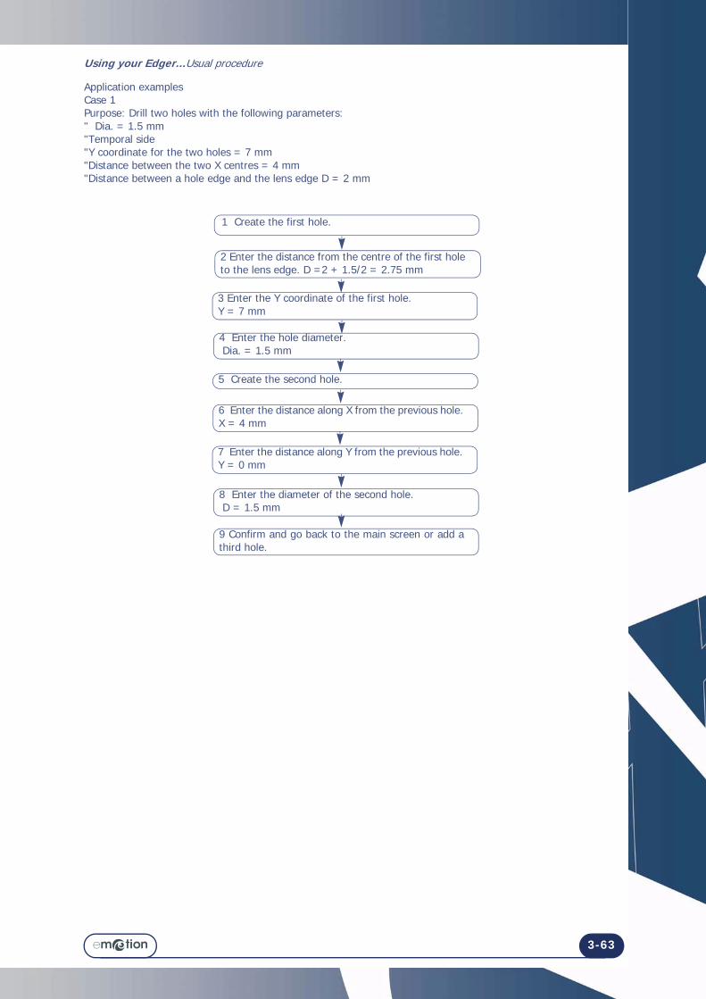
Application examplesCase 1Purpose: Drill two holes with the following parameters:" Dia. = 1.5 mm "Temporal side "Y coordinate for the two holes = 7 mm"Distance between the two X centres = 4 mm "Distance between a hole edge and the lens edge D = 2 mm
1 Create the first hole.
2 Enter the distance from the centre of the first hole to the lens edge. D =2 + 1.5/2 = 2.75 mm
3 Enter the Y coordinate of the first hole.Y = 7 mm
4 Enter the hole diameter. Dia. = 1.5 mm
5 Create the second hole.
6 Enter the distance along X from the previous hole.X = 4 mm
7 Enter the distance along Y from the previous hole.Y = 0 mm
8 Enter the diameter of the second hole. D = 1.5 mm
9 Confirm and go back to the main screen or add a third hole.

Using your Edger...Usual procedure
3-64
Centering a lens marked with a frontofocometer
- The central point must be on the red cross.- The lateral points must be on the horizontal line.
Centering a bifocal lens
- The top of the segment must be tangential to the red line.- The sides of the segment must be tangential to a pair of vertical lines of the same colour.
Centering a dotted progressive lens
- The distant vision marking must be on the red cross. - The axis marking must be parallel to the horizontalred lines.
Centering a progressive lens with micro engravings
- The distant vision marking must always be on the red cross.- The micro engravings must be aligned with a horizontal line, with the lens centered using the vertical lines of the same colour.

Using your Edger...Usual procedure
3-65
3.4.3 BLOCKING/CENTERING
The numbers of this illustration refer to the step numbers below.
Follow the steps below to block a lens:
1 On the main screen, select the side to be blocked by pressing directly on the frame concerned (right or left eye). NOTE: The blocking screen replaces the main screen. A red and green letter at the top of the screen (L or R) shows which side will be blocked.
2 Place a lens holder, corresponding to the lens to be blocked, on the ground glass screen. NOTE: To block a lens which has to be regrooved, or a small lens (<45 mm), it is preferable to use the fitted lens holder (small diameter ) (P/N S390017) .
4 Select the type of lens to be blocked.Result: A coloured target corresponding to the type of lens selected is displayed in the main window.
5 Position the lens to be blocked so that the markings match the target.
3 Place the lens to be blocked, after marking it, on its holder.
6 Place a block fitted with an adhesive in the blocker head. CAUTIONTHE USE OF ADHESIVES WHICH ARE NOT SPECIFICALLY RECOMMENDED BY BRIOT MAY RESULT IN MALFUNCTIONS DURING SUBSEQUENT EDGING PHASES.
7 Start the lens blocking operation.
8 When the blocking operation is complete, remove the blocked lens from its holder.

Using your Edger...Usual procedure
3-66
PRODUCING A JOB WITH RIMLESS FINISHING
Screen 3-15: Example of the production of a job with rimless finishing
Normal Type With polishing Without safety-bevel
Polycarbonate lens
Rimless
Start the edging process

Using your Edger...Usual procedure
3-67
3.4.4 EDGING
3.4.4.1 PRODUCING A JOB WITH RIMLESS FINISHING
3.4.4.1.1 OBJECT
Produce a job with the following characteristics:
Polycarbonate > Normal lens > Rimless finishing > No safety-bevel > Polishing
3.4.4.1.2 PROCEDURE
To carry out the job described above, proceed as follows:
Flow chart 3-3: Production of a job with Drilling finishing
Note: To fami l iar ize yourself with the icons associated with each step, refer to the screen on the left page.
Call a job number.
Select POYCARBONATE lens material.
Select NORMAL lens type.
Select RIMLESS finishing.
Select POLISHING option.
Place the lens in the edging chamber.
Start the edging process.
Select NO SAFETY-BEVEL.

Using your Edger...Usual procedure
3-68
PRODUCING A JOB WITH GROOVE FINISHING
Illustration 3-4: Example of the production of a job with Groove finishing
Normal Type With polishing
0.2 mm front face safety-bevel
0.2 mm rear face safety-bevel
33% sub-finishing
Groove Finishing
HI plastic lens
Start the edging process

Using your Edger...Usual procedure
3-69
3.4.4.2 PRODUCING A JOB WITH GROOVE FINISHING
3.4.4.2.1 OBJECT
Produce a job with the following characteristics:
HI plastic > Normal lens > Grooving > 33 % Groove > Front and rear safety-bevels > Polishing
Safety-bevel parameters: front depth = 0.20 mm / rear depth = 0.20 mm
3.4.4.2.2 PROCEDURE
To carry out the job described above, proceed as follows:
Flow chart 3-4: Production of a job with Drilling finishing
Note: To fami l iar ize yourself with the icons associated with each step or obtain more detai ls of the act ion required, refer to the screen on the left page.
Call a job number.
Select HI plastic lens material.
Select NORMAL lens type.
Select GROOVE finishing.
Select 33% sub-finishing.
Select POLISHING option.
Place the lens in the edging chamber.
Start the edging process.
Select 0.2 mm FRONT and REAR SAFETY-BEVELS. Note: The front safety-bevel value is 0 or 0.2 mm. The rear safety-bevel value is 0, 0.2, 0.4, 0.6mm.

Using your Edger...Usual procedure
3-70
Screen 3-16: Example of the production of a job with a bevel
PRODUCING A JOB WITH BEVEL FINISHING
Fragile type Rear face safety-bevel
Without polishing
Without oversize
Mineral lens
Bevel finishing
50% Bevel

Using your Edger...Usual procedure
3-71
3.4.4.3 PRODUCING A JOB WITH BEVEL FINISHING
3.4.4.3.1 OBJECT
Produce a job with the following characteristics:
Mineral > Fragile lens > 1/2-1/2 bevel > Rear safety-bevel = 0.40 mm > Without polishing
3.4.4.3.2 PROCEDURE To carry out the job described above, proceed as follows:
Flow chart 3-5: Production of a job with Bevel finishing
Tip! To famil iar ize yoursel f with the icons associated with each step or obtain more detai ls of the act ion required, refer to the screen on the left page.
3.4.4.3.3 HINTS
When the edging cycle is finished, remove the edged lens without removing the block so as to be able to retouch it if necessary.
If you are unsure about the type of bevel positioning, we advise you to choose Manual type from the main screen. During the cycle, when the manual finishing screen is displayed, press the Manual Bevel button, select the type of bevel you wish and visualise the position of the bevel apex directly on the screen.
3.4.4.3.4 LIMITS
> If the maximum thickness of the lens is less than 2 mm, the applied bevel will automatically be of 1/2 - 1/2 type, whichever type of bevel is selected initially.
See also see “Produce a manual bevel”, page 82 and see “Operating ranges:”, page 87.
Select the type of REAR safety-bevel for 0.4 mm (SB No. 2)
Call a job number.
Select MINERAL lens material.
Select FRAGILE lens type.
Select BEVEL finishing.
Select 50% sub-finishing.
Place the lens in the edging chamber.
Start the edging process.

Using your Edger...Usual procedure
3-72
MODIFYING A SHAPE - DIGIFORM
Illustration 3-5: Example of shape modification - Digiform
Call up a shape
Shape modification keysConfirm
Storage source for shapes and templates

Using your Edger...Special cases
3-73
3.5 SPECIAL CASES3.5.1 MODIFYING A SHAPE - DIGIFORM FUNCTION
3.5.1.1 INTRODUCTION
In some cases the pattern used for drilled frames or nylor frames does not match the required shape.The Digiform function used on the emotion can modify any shape to produce a new pattern.3.5.1.2 PROCEDURE
The numbers of this illustration refer to the step numbers below.Follow the steps below to modify a shape (Digiform function):
*NOTE:This new shape can be saved in the patterns data base, with new references.
1 Call up the initial saved shape.
2 Modify the shape as required (see paragraph Description of the Digiform function, below).
4 Use the new shape as if it were a new pattern.*
3 Confirm the modifications and quit the Digiform function.

Using your Edger...Specia l cases
3-74

Using your Edger...Special cases
3-75
3.5.2 APPLYING AN OVERSIZE
3.5.2.1 WHY?
If you find that the overthickness applied to the job by default is not suitable, you can decide to apply an oversize which will be applied to the lens to be edged.
3.5.2.2 HOW?3.5.2.2.1 PRELIMINARY CONDITION
> You must enter the oversize value BEFORE edging the lens.
3.5.2.2.2 PROCEDURE
From the main application screen (Edging tab), after selecting all the job characteristics, proceed as follows.Note: Using the touch screen, press the zones or buttons shown.
Flow chart 3-6: Entering an oversize value
3.5.2.2.3 RESULT: = The lens is edged and the initial dimension has been increased or decreased by the entered value.
> You may check the lens diameter with a digital caliper and retouch it if necessary.
3.5.2.3 HINTS
Always check that the type of oversize displayed is indeed that which you wish to apply.
3.5.2.4 IMPORTANT NOTES
> The retouch is applied to the width of the lens. The height of the lens is recalculated to retain the proportions of the initial shape.
> For the same job, the oversizing applied to the right lens is not automatically applied to the left lens. > In the case of a new edging cycle for the same lens (also called «re-edging»), the oversizing applied to the
first lens will be automatically applied to the second.
3.5.2.5 LIMITS
> +/- 0.5 mm to boxing width
Enter the correction value.
Check the entered value.

Using your Edger...Specia l cases
3-76
3.5.3 EDGING THE LEFT LENS WITH DIFFERENT PARAMETERS FROM THOSE OF THE RIGHT LENS
3.5.3.1 PRINCIPLE
> If the left and right lenses of your job do not have the same characteristics, you may modify the edging data from one lens to another using the buttons available in the Edging tab.
CAUTION! For the same job, the following characteristics cannot be modified from one lens to another:• Lens material • Finishing type• Polishing type.
You may only modify the following characteristics:• Lens type • Sub-finishing type • Safety-bevel type.
3.5.3.2 PROCEDURE
To modify the parameters from one lens to another, proceed as follows.Note: Using the touch screen, press the zones or buttons shown.
Flow chart 3-7: Modification of parameters from one lens to another
Change the characteristics as you wish.
Edge the first lens.
Check the parameter values.
Select the left side.

Using your Edger...Special cases
3-77
3.5.4 EDGING SEVERAL LENSES IDENTICALLY
3.5.4.1 PRINCIPLE
> You wish to edge several lenses with similar characteristics.
3.5.4.2 PROCEDURE
Flow chart 3-8: Edging lenses with identical characteristics
= The lens is edged again, with the same characteristics as the previous edging.
Tip! In this way you can group together s imi lar lenses without enter ing the same character ist ics for each new edging cycle.
Fit a new lens on the lens holder shaft.
Do you want to re-edge the same lens ?

Using your Edger...Specia l cases
3-78
3.5.5 CHECKING A FINISHING BEFORE THE LENS IS EDGED
3.5.5.1 PRINCIPLE
> You may wish to check the position of the desired finishing - bevel and groove - before beginning the lens edging cycle.
> You may also wish to position the finishing yourself when running a job. > You may be automatically redirected to this screen.
Example: The desired finishing position cannot be applied to the lens being edged.A special screen allows you to visualise the finishing and modify its position, if desired.
3.5.5.2 PRESENTATION
3.5.5.2.1 MANUAL BEVEL SCREEN
Screen 3-17: Manual bevel screen
IMPORTANT NOTE
> The indices of zones A and B indicate the same finishing angular position. When you move one, the other moves as well.
C
Movement of the index
Angular position Index
Front face developed curveBevel apex developed curve
Rear face developed curve
Lens section at position of index
Lens thickness
A
B Developed lens profile
Lens shape seen from the front
Sub-Finishing
Width
Re-feeling

Using your Edger...Special cases
3-79
3.5.5.2.2 MANUAL GROOVE SCREEN
Screen 3-18: Manual groove screen
IMPORTANT NOTE
> The indices of zones A and B indicate the same finishing angular position. When you move one, the other moves as well.
C
Movement of the index
Angular position Index
Front face developed curve
Groove centre developed curve
Rear face developed curve
Lens section at position of index
Lens thicknessSub-Finishing
A
B Developed lens profile
Lens shape seen from the front
Depth Width
Re-feeling
Using your Edger...Specia l cases
3-80
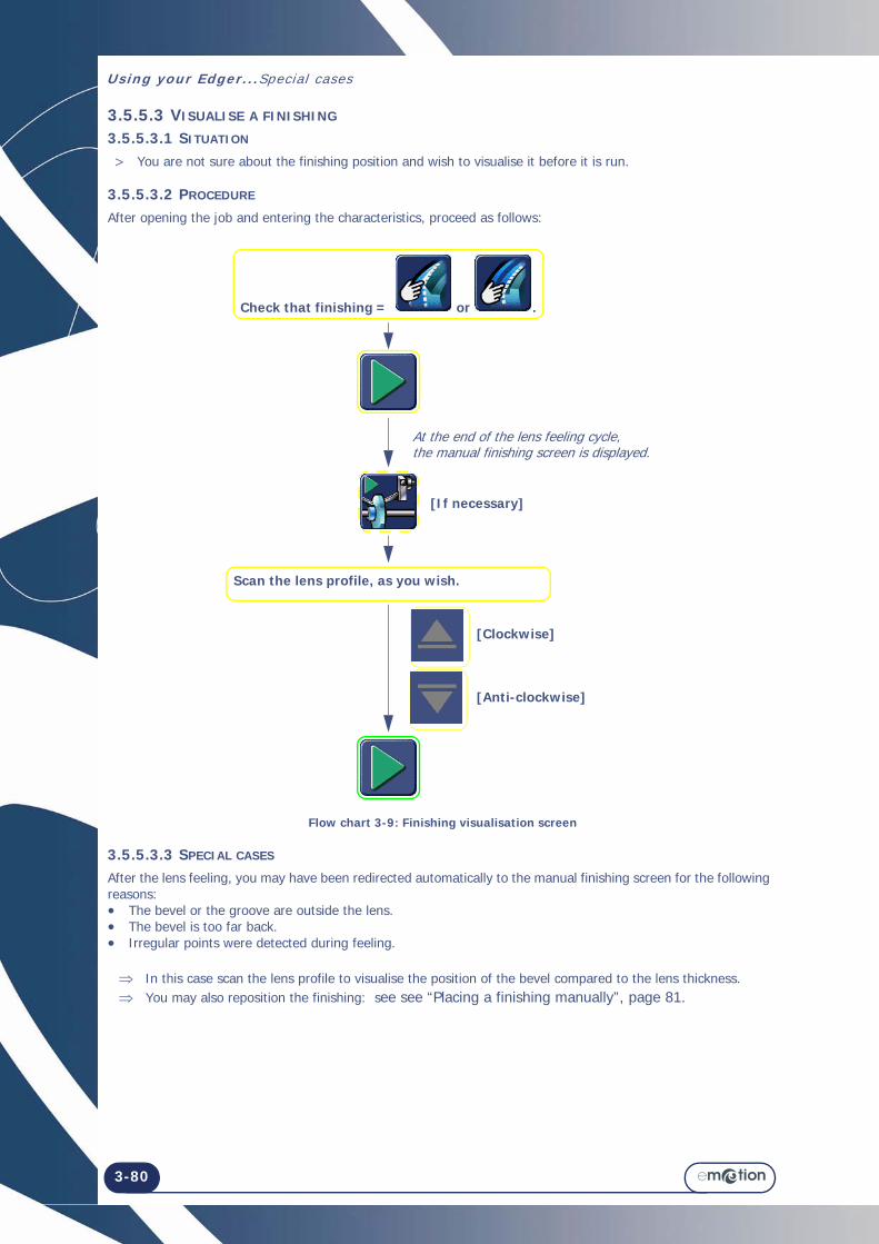
3.5.5.3 VISUALISE A FINISHING
3.5.5.3.1 SITUATION
> You are not sure about the finishing position and wish to visualise it before it is run.
3.5.5.3.2 PROCEDURE
After opening the job and entering the characteristics, proceed as follows:
Flow chart 3-9: Finishing visualisation screen
3.5.5.3.3 SPECIAL CASES
After the lens feeling, you may have been redirected automatically to the manual finishing screen for the following reasons:• The bevel or the groove are outside the lens.• The bevel is too far back.• Irregular points were detected during feeling.
In this case scan the lens profile to visualise the position of the bevel compared to the lens thickness. You may also reposition the finishing: see see “Placing a finishing manually”, page 81.
Check that finishing = or .
[If necessary]
At the end of the lens feeling cycle, the manual finishing screen is displayed.
Scan the lens profile, as you wish.
[Clockwise]
[Anti-clockwise]

Using your Edger...Special cases
3-81
3.5.5.4 PLACING A FINISHING MANUALLY
3.5.5.4.1 PRINCIPLE
> You wish to visualise the lens thickness and adjust the finishing position.
3.5.5.4.2 GENERAL PROCEDURE
After opening the job and entering the characteristics, proceed as follows:
Flow chart 3-10: Placing a finishing manually
IMPORTANT NOTES
> The finishing position can be modified in 3 ways: Right/left offset, width and depth modification for grooves, height modification for bevels. Only the apex of the bevel or the middle of the groove is displaced along this point. The opposite side remains fixed and the curve of the finishing is unchanged.
> If you wish to reposition the whole finishing, move it in one direction to the required position. Then do the same from the opposite point.
3.5.5.4.3 SPECIAL CASES
After the lens feeling, you may have been redirected automatically to the manual finishing screen for the following reasons:• The bevel or the groove are outside the lens.• The bevel is too far back.• Irregular points were detected during feeling. You may then reposition the finishing as shown in the flow chart above.
Select the finishing point whose position you wish to modify.Zone : Press the axis of your choice: top, bottom, temporal, nasal.A
Move the finishing and position it as you wish.
[If necessary]
At the end of the second lens feeling cycle, the manual finishing screen is displayed.
[To the rear]
[To the front]
OR
OR
Check that finishing = or .
The axis turns from red to green.
Using your Edger...Specia l cases
3-82
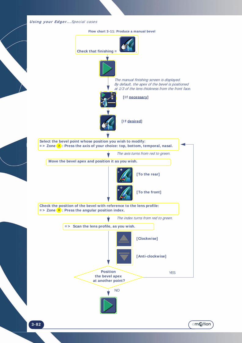
Flow chart 3-11: Produce a manual bevel
[If desired]
[If necessary]
The manual finishing screen is displayed.By default, the apex of the bevel is positioned at 1/3 of the lens thickness from the front face.
Select the bevel point whose position you wish to modify:=> Zone : Press the axis of your choice: top, bottom, temporal, nasal.A
Move the bevel apex and position it as you wish.
[To the rear]
[To the front]
=> Scan the lens profile, as you wish.
[Clockwise]
[Anti-clockwise]
Check that finishing = .
Check the position of the bevel with reference to the lens profile:=> Zone : Press the angular position index.B
Position the bevel apex
at another point?
YES
NO
The axis turns from red to green.
The index turns from red to green.

Using your Edger...Special cases
3-83
3.5.5.5 PRODUCE A MANUAL BEVEL
3.5.5.5.1 PRINCIPLE
> You wish to visualise the lens thickness and adjust the finishing position.
3.5.5.5.2 PROCEDURE
To produce a manual bevel:1. Call up the job.2. Enter its characteristics.3. Proceed as shown on the flow chart ”Produce a manual bevel 3-11”
3.5.5.5.3 HINTS
When the edging cycle is finished, remove the lens from the edging chamber without removing the block so as to be able to retouch it if necessary.
Check the lens dimensions and finishing.
3.5.5.5.4 IMPORTANT NOTES
> The maximum distance between the apex of the bevel and the front face is 5 mm. > The finishing position can be modified in four points: top, bottom, temporal, nasal. Only the bevel apex is
displaced along this point. The opposite side remains fixed and the curve of the bevel is unchanged. > If you wish to reposition the whole bevel, move the bevel apex in one direction to the required position. Then
do the same from the opposite point.
3.5.5.5.5 LIMITS
> If the maximum thickness of the lens is less than 2 mm, the applied bevel will automatically be of 50% type, whichever type of bevel is selected initially.
> To make a safety-bevel of any type, the minimum distance between the bevel apex and the front/rear face must be greater than 1.6 mm. If it is less than 1.6 mm at any point of the lens, the safety-bevel will not be produced at this point.

Using your Edger...Specia l cases
3-84
Flow chart 3-12: Producing a manual groove
Select the groove point whose position you wish to modify: => Zone : Press the axis of your choice: top, bottom, temporal, nasal.
[If desired]
[If necessary]
The manual finishing screen is displayed.By default the middle of the groove is positioned at 1/3 of the lens thickness from the front face.
A
Move the middle of the groove and position it as you wish.
[To the rear]
[To the front]
=> Scan the lens profile, as you wish.
[Clockwise]
[Anti-clockwise]
Check that finishing = -
Check the position of the groove with reference to the lens profile:=> Zone : Press the angular position index.B
Position the middle of the groove
at another point?
YES
NO
The axis turns from red to green.
The index turns from red to green.
Modify the groove parameters, if desired.
[Depth]
[Width]

Using your Edger...Special cases
3-85
3.5.5.6 PRODUCE A MANUAL GROOVE
3.5.5.6.1 PRINCIPLE
> You wish to visualise the lens thickness and define the curve and the position of the groove.
3.5.5.6.2 PROCEDURE
To produce a manual groove:1. Start the edging process2. Enter its characteristics.3. Proceed as shown on the flow chart ”Producing a manual groove 3-12”.
3.5.5.6.3 HINTS
When the edging cycle is finished, remove the lens from the edging chamber without removing the block so as to be able to retouch it if necessary.
Check the lens dimensions and finishing.
3.5.5.6.4 IMPORTANT NOTES
> Only plastics can be grooved. > The minimum thickness of the lens must be equal to or greater than 1mm to produce a groove. > The groove position can be modified in 4 ways: Right or left offset, width and depth modifications. Only the
middle of the groove is displaced along this point. The opposite side remains fixed and the curve of the groove is unchanged.
> The relationship between the minimum Lens face - Groove edge distance and the depth of the groove will always be adjusted automatically to guarantee the lens resistance.
3.5.5.6.5 LIMITS
> If the maximum thickness of the lens is less than 2 mm, the applied groove will automatically be of 50% type, whichever type of groove is selected initially.
> To make a groove of any type, the minimum distance between the front face of the lens and the front edge of the groove (or the rear face and rear edge) must be greater than 0.4 mm. If it is less than 0.4 mm at any point of the lens, the groove will not be produced.
> The safety-bevel(s) of a grooved lens will be maintained if the retouch value is less than 0.2mm to the diameter.
3.5.5.7 FEEL THE LENS AGAIN
> If the diameter of the lens being felt is too small, the warning message "Lens too small" is displayed and you transfer to the manual finishing screen.
You may then feel the lens three times successively. The lens is felt 0.5 mm closer to the interior each time.
If the three successive feeling operations are not enough, the lens is too small and cannot be edged.
Confirm the message.
Complete the cycle and retrieve the lens.
> If irregular points have been detected during the first phase of the cycle, the message "Irregular points" is displayed and you transfer to the manual finishing screen. We advise you to repeat the lens feeling cycle.

Using your Edger...Specia l cases
3-86

Using your Edger...Operating ranges:
3-87
3.6 OPERATING RANGES: 3.6.1 POINTS TO REMEMBER
→ Lens
Diameter of uncut lens before edging = diameter of 80 mm plus 10 mm of maximum eccentricity, i.e. a diameter of 100 mm without decentering.
Thicknesses:
Maximum thickness at the edge of the uncut (plastic) lens = 18 mm
Maximum thickness at the edge of the uncut (mineral) lens = 16 mm
Minimum thickness at the centre of the uncut lens = 1.2 mm.
If the thickness of the finished lens (rimless finishing) detected during lens feeling > 11 mm (17 mm for bevel finishing on a plastic lens - 15 mm for bevel finishing on a mineral lens), edging is impossible
→ Shape
Minimum height of the shape in rimless = 17.50 mm
Minimum height of the shape in bevel = 19.10 mm. → Minimum lifespan of the edging wheels:
Mineral roughing = 10000 lenses
Plastic roughing = 50000 lenses
Finishing = 8000 lenses - 10000 lenses
Polishing = 6000 lenses
Safety-bevel = 5000 lenses per wheel side
Grooving = 5000 lens. → Beveling
Minimum lens thickness to produce the type of bevel desired = 2 mm
If maximum thickness of felt lens less than 2 mm, the bevel is automatically type 1/2 - 1/2.
→ Grooving
Minimum/maximum width = 0.6 to 1.2 mm
Minimum/maximum depth = 0 to 0.8 mm.
Minimum distance between the front face of the lens and the front edge of the groove (or rear face and rear edge) to produce a groove = 0.2 mm.
→ Drilling
Minimum hole diameter = diameter of the mill bit, i.e. 1 mm
Lifespan of the mill bit = 1 hr of total drilling, all lens materials together
Maximum hole depth (= length of the mill bit) = 8 mm
Maximum hole diameter = 10 mm
Angle = 10°
Accuracy of the drilling angle = +/- 1°
Positioning of holes = +/- 0.1 mm
Maximum ten holes per lens, for all types of holes.
An elongated hole, a countersunk hole or a notch count for two holes.

Using your Edger...Operat ing ranges:
3-88
→ Safety-bevel
Maximum depth = 0.6 mm in increments of 0.1 mm
Retouching with safety-bevel is possible if the value of the retouch is less than 0.2 mm (at Boxing width)
Minimum distance between the apex of the bevel and the front/rear face to produce a safety-bevel 1.6 mm
Minimum distance between the front face of the lens and the front edge of the groove (or rear face and rear edge) to produce a safety-bevel = 0.4 mm
→ Accuracy of the edger
Dimensional accuracy = +/- 0.06 mm at diameter
Axis setting accuracy = +/- 0.5° per lens (entry+blocking+edging).

Using your Edger...Operating ranges:
3-89
3.6.2 ILLUSTRATION OF FINISHING LIMITS
3.6.2.1 RIMLESS FINISHING
Illustration 3-6: Limits of production of a rimless lens
3.6.2.2 BEVEL FINISHING
Illustration 3-7: Limits of production of a bevel
3.6.2.3 INCLINED GROOVE FINISHING
Illustration 3-8: Limits of production of an inclined groove
Front face
Rimless
Min. height of finished lens = 17.50 mm
Front faceMin. height of finished lens = 19.10 mm
Bevel height = 0.8 mm
Bevel width = 2.8 mm
Fixed angle = 10°
Max. depth of groove = 0.8 mm
Min. diameter of finished lens = 18.60 mm (if depth = 0.8 mm) = 18.25 mm (if depth = 0.6 mm)
Front face
Groove width = 0.6 mm to 1.2 mm
Diameter of finished lens = 17 + Depth of groove x 2

Using your Edger...Operat ing ranges:
3-90
3.6.3 DRILLING
3.6.3.1 CONDITIONS
> Only CR39, polycarbonate, high index (HI) and Trivex™ materials can be drilled. > A mineral lens cannot be drilled.
3.6.3.2 LIMITS OF HOLE POSITIONING
> Whatever the type of hole, it must be drilled in a specific zone which is defined following the diagrams below. > The following constraints must be observed:
→ The circle radius beyond which drilling is possible:
Note: When i t is impossible to dr i l l a hole (hole posit ioned in the end-pieces, notch passing through the centre of the shape, this hole is shown in black in the screen. Some holes displayed in blue in the screen may be impossible to dri l l after they have been felt (holes too deep, unadapted angle, unadapted end-piece, etc.). In these cases, these holes wi l l be displayed in gray in the screen and only marked with the mi l l b it end (with maximum incl inat ion angle) dur ing the dr i l l ing phase, once the operator has accepted the marking.
→ The ring formed by the edge of the lens and the internal perimeter of the lens beyond which drilling is not permitted:
ALL HOLES, WHATEVER THE TYPE, MUST BE WITHIN A 12 mm RING.
Note: If a job includes a hole placed at a distance of more than 12 mm from the edge of the shape, the fol lowing message is displayed: « Hole deleted. At least one of the holes cannot be dr i l l ed. Do you want to cont inue? ». If you reply Yes: The ent ire dr i l l ing plan is ignored, the lens is not dri l led and f in ished in r imless. If you r eply No, you can remove the lens from the dr i l l ing chamber.
Zone inside which drilling is not permitted.
Zone inside which drilling is permitted.
Min. distance from centre of block -> centre of hole = 19 mm
Max. distance from drill bit centre -> edge of lens = 12 mm
Zone inside which drilling is not permitted.
Zone inside which drilling is permitted.
Using your Edger...Operating ranges:
3-91
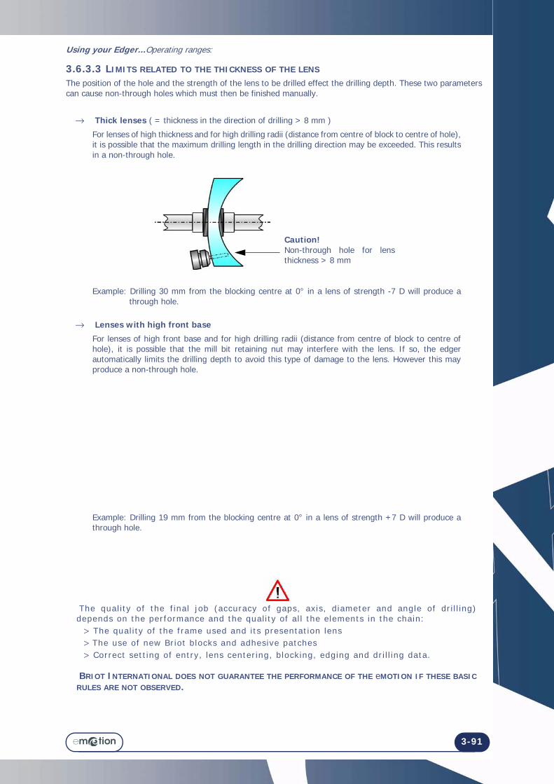
3.6.3.3 LIMITS RELATED TO THE THICKNESS OF THE LENS
The position of the hole and the strength of the lens to be drilled effect the drilling depth. These two parameters can cause non-through holes which must then be finished manually.
→ Thick lenses ( = thickness in the direction of drilling > 8 mm )
For lenses of high thickness and for high drilling radii (distance from centre of block to centre of hole), it is possible that the maximum drilling length in the drilling direction may be exceeded. This results in a non-through hole.
Example: Drilling 30 mm from the blocking centre at 0° in a lens of strength -7 D will produce a through hole.
→ Lenses with high front base
For lenses of high front base and for high drilling radii (distance from centre of block to centre of hole), it is possible that the mill bit retaining nut may interfere with the lens. If so, the edger automatically limits the drilling depth to avoid this type of damage to the lens. However this may produce a non-through hole.
Example: Drilling 19 mm from the blocking centre at 0° in a lens of strength +7 D will produce a through hole.
The qual i ty of the f inal job (accuracy of gaps, axis, diameter and angle of dr i l l ing) depends on the performance and the qual i ty of al l the elements in the chain: > The qual i ty of the frame used and i ts presentat ion lens > The use of new Briot blocks and adhesive patches > Correct sett ing of entry, lens center ing, blocking, edging and dr i l l ing data.
BRIOT INTERNATIONAL DOES NOT GUARANTEE THE PERFORMANCE OF THE eMOTION IF THESE BASIC RULES ARE NOT OBSERVED.
Caution!Non-through hole for lens thickness > 8 mm

Using your Edger...Operat ing ranges:
3-92
3.6.4 LIMITATION OF THE LENS CHARACTERISTICS (BLOCKER/PATTERN)The emotion is designed to block lenses with the following characteristics:3.6.4.1 LENS CHARACTERISTICS
DIAMETER
INDEX & COLOUR The index and colour have no effect on the centering function.
TREATMENT The lens treatment, in particular the anti-reflective coating, has no effect on the centering function.
HEIGHT
Lay the lens down on the lens holder and measure the maximum "height" from the centre of the lens to the top of the holder pins.
Diameter of uncut lens : 30 to 100 mm

4 CONFIGURATION

4-94

4-95
=> Configuration
4.1 PRESENTATION OF CONFIGURATION MENUS4.1.1 PRESENTATION OF THE CONFIGURATION MENUS ACCESS SCREEN
4.1.1.1 SCREEN DESCRIPTION
The first user technical screen provides access to the user technical menus, such as the settings menu and the statistics menu. The tests, maintenance and personalisation menus are intended for the technician.
Screen 4-1: Configuration menus access screen
Tip! The type of menu is shown by the icon which is displayed on the top r ight of the current screen. If you are working with the Personal isat ion screen, the edger wi l l be dis played on the top r ight of the screen.
4.1.1.2 ACCESS / EXIT
4.1.1.2.1 TO ACCESS THE SCREEN
To reach the configuration menus access screen, press on the main application screen, in the Job selection/creation tab.Result: The user technical menus screen is displayed.
4.1.1.2.2 TO EXIT THE SCREEN
To leave the configuration menus access screen, press the button.Result: The machine restarts. The main application screen is displayed again.
SETTINGS menu
PERSONALISATION menuYou are in the User Technical menu
MAINTENANCE menu
TESTS menu

Configuration...Presentat ion of conf igurat ion menus
4-96
4.1.2 PRESENTATION OF THE PERSONALISATION MENUS ACCESS SCREEN 4.1.2.1 SCREEN DESCRIPTION The personalisation menus access screen is shown below.
Screen 4-2: Personalisation menus access screen
4.1.2.2 ACCESS / EXIT
4.1.2.2.1 TO ACCESS THE SCREEN
4.1.2.2.2 TO EXIT THE SCREEN
Adjustment of the setting values
General operation
You are in the personalisation menu
Frame and lens values correction screen
x 2

4-97
=> Configuration
4.2 CONFIGURATION OF FINISHING PARAMETERS DEFAULT VALUES 4.2.1 PRESENTATION
4.2.1.1 PRINCIPLE
> You have your own way of working and wish to gain time by configuring your own default values.
4.2.1.2 SCREEN DESCRIPTION
The configuration screen for the finishing parameters default values is shown below:
Screen 4-3: Default values configuration screen
For a detailed description of the buttons see, See Sub-finishing and associated parameters, chapter 3.

Configuration...Configurat ion of f in ishing para meters default values
4-98
4.2.1.3 ACCESS / EXIT
4.2.1.3.1 TO ACCESS THE SCREEN
4.2.1.3.2 TO EXIT THE SCREEN
4.2.2 GENERAL PROCEDURE
Follow the steps below to set the default value of a parameter:
Flow chart 4-1: Configuration of finishing parameter default values
4.2.3 SAVING THE NEW CONFIGURATION
> When you leave the screen, the default values that you have selected are memorised automatically. > When you return to the application screen, you will see that the default values displayed are those you have
just entered.
4.2.4 LIMITS
The information given in the tables below completes the values referred to in Using > Application screen icons > Sub-finishings and associated parameters.
The default values that you wish to be memorised must be within the limits given by Briot. Any value outside the interval shown cannot be validated.The numeric key pad will remain displayed until you have entered a correct value. If you wish to quit the numeric key pad, use the ESC key. The previous default value will then be applied again.
x 3
#1 Press the key-in button of the chosen parameter.
#2 Using the numeric key pad, enter your chosen default value within the limits displayed above the key pad screen.
#3
#4 Continue in the same way for each default value that you wish to change.

Configuration...Configuration of finishing parameters default values
4-99
4.2.4.1 BEVEL
4.2.4.2 GROOVE
TABLE 1:
Sub-finishing
type
Briot default values
Lower limit
Upper limit Incrementation
1 mm -5 mm 5 mm 0.01 mm
4 D 0.25 D 12 D 0.25 D
33% 0 100% 1 %
0.8 mm 0.8 mm 3 mm 0.1 mm
TABLE 2:
Sub-finishing
type
Briot default values
Lower limit
Upper limit Incrementation
1 mm -5 mm 5 mm 0.01 mm
4 D 0.25 D 12 D 0.25 D
33% 0 100% 1 %
0.4 mm 0 1 mm 0.1 mm
0.6 mm 0.6 mm 1.2 mm 0.1 mm

Configuration...Configurat ion of f in ishing para meters default values
4-100
4.2.4.3 SAFETY-BEVEL
TABLE 3:
Safety-bevel type
Briot default values
Lower limit
Upper limit Incrementation
0.2 mm 0 0.6 mm 0.1 mm
0.2 mm 0 0.6 mm 0.1 mm

Configuration...Configuration of finishing parameters default values
4-101

Configuration...Configurat ion of f in ishing para meters default values
4-102
Screen 4-4: Adjustment of the setting values (1)
To adjust the position of the apex of the bevel
To adjust the depth of the rear safety-bevel
To adjust the depth of the front safety-bevel
To adjust the position of the middle of the groove
Adjustment of the setting values
Exit
RESET DURING ADJUSTMENT

Configuration...Adjustment of the setting values
4-103
4.3 ADJUSTMENT OF THE SETTING VALUES4.3.1 PRELIMINARY REMARKS
> The machine is factory adjusted to meet the needs and requirements of the majority of users. > Any modifications of the standard setting values can affect the performance of the machine. > If you wish nonetheless to use the values adjustment function, first target your needs with precision and then
modify the values with full knowledge of our recommendations.
4.3.2 PROCEDURE
To adjust the setting values, proceed as follows:
Flow chart 4-2: Adjustment of the setting values
#1
#2
#3
#4 Press the value to be corrected.
#5 Enter a value using the numeric key pad.
#6
#7

Configuration...Adjustment of the sett ing values
4-104
Screen 4-5: Correction of frame and lens values
Exit
To enter a correctionfor plastic and metal frames
To enter a correction for plastic frames
To enter a correction for CR39 lenses
To enter a correction for High Index lenses
To enter a correctionforTrivex™ lenses
Adjustment of the setting values
NOT TAKEN INTO ACCOUNT DURING
ADJUSTMENT
To enter a correctionfor Polycarbonate lenses

Configuration...Correction of frame and lens values
4-105
4.4 CORRECTION OF FRAME AND LENS VALUES4.4.1 PRELIMINARY REMARKS
> The machine is factory adjusted to meet the needs and requirements of the majority of users. > Any modifications of the standard setting values can affect the performance of the machine. > If you wish nonetheless to use the values adjustment function, first target your needs with precision and then
modify the values with full knowledge of our recommendations.
4.4.2 PROCEDURE
To adjust the setting values, proceed as follows:
Flow chart 4-3: Correction of frame and lens values
#1
#2
#3
#4 Press the value to be corrected.
#5 Enter a value using the numeric key pad.
#6
#7

Configuration...Correct ion of frame and lens values
4-106

Configuration...Configuration of general operating parameters
4-107
4.5 CONFIGURATION OF GENERAL OPERATING PARAMETERS4.5.1 PRESENTATION
4.5.1.1 PRINCIPLE
> You define the machine's general operating mode.
4.5.1.2 SCREEN DESCRIPTION
The setting screen for the machine's general operating parameters is shown below:
Screen 4-6: Setting the machine's general operating parameters4.5.1.3 ACCESS / EXIT
4.5.1.3.1 TO ACCESS THE SCREEN
4.5.1.3.2 TO EXIT THE SCREEN
Dialog language
Size compensation according to water temperature
Size compensation according to wheel condition
Size compensation according to frame curvature
Continue to press the button until the desired language is displayed.
To save the settings
You are in themachine's general operating mode
x 3

Configuration...Configurat ion of general operat ing parameters
4-108
4.5.2 CONFIGURATION OF THE FUNCTIONS
4.5.2.1 SELECTING THE DIALOG LANGUAGE
To select the dialog language, press this button : until the desired language is displayed.
4.5.2.2 ACTIVATING SIZE COMPENSATION ACCORDING TO TEMPERATURE
4.5.2.2.1 PRINCIPLE
> The water temperature affects the degree of expansion of the wheels. > Activating the temperature compensation automatically corrects for the expansion of the edging wheels and
the lens due to water temperature variations. > Enabling the temperature compensation is strongly recommended if you work in closed circuit.
4.5.2.2.2 PROCEDURE
To enable the temperature compensation:
4.5.2.3 ENABLING SIZE COMPENSATION ACCORDING TO WHEEL CONDITION
4.5.2.3.1 PRINCIPLE
> A wheel becomes very abrasive after dressing. This can lead to some instability in the dimensions of edged lenses following wheel dressing.
> The wheel condition compensation function takes this effect into account and allows for compensation of the lens size after the wheel has been dressed.
4.5.2.3.2 PROCEDURE
To enable the wheel condition compensation:
4.5.2.4 ENABLING SIZE COMPENSATION ACCORDING TO THE BOWING/FLATTENING OF THE FRAME
4.5.2.4.1 PROCEDURE
To enable the frame bowing/flattening compensation:
4.5.3 SAVING THE NEW CONFIGURATION
When you quit the screen, the message, « Do you wish to save the new configuration? » is displayed.you have three possibilities: > Confirm the message: The configuration is taken into account and you return to the personalisation menus
access screen. > Do not confirm the message: The configuration is not taken into account and you return to the
personalisation menus access screen. The previous setting is retained. > Cancel the configuration: You return to the configuration screen. Reselect the operating parameters you
have chosen.
When you return to the application screen and begin an edging cycle, you will see that the general operating parameters have been saved.

Configuration...Configuration of Communication parameters
4-109
4.6 CONFIGURATION OF COMMUNICATION PARAMETERS4.6.1 PRESENTATION
4.6.1.1 PRINCIPLE
> You enable or disable the communication functions according to the peripheral equipment connected to the machine
4.6.1.2 SCREEN DESCRIPTION
The setting screen for the machine communications is shown below:
Screen 4-7: Setting the communication parameters4.6.1.3 ACCESS / EXIT
4.6.1.3.1 TO ACCESS THE SCREEN
4.6.1.3.2 TO EXIT THE SCREEN
To save the settings
You are in thecommunication parameters screen
x 3

Configuration...Configurat ion of Communicat ion parameters
4-110
4.6.1.4 ENABLING / DISABLING COMMUNICATION FUNCTIONS
4.6.1.4.1 PRINCIPLE
> According to the peripheral equipment connected to the machine, the associated communication function must be enabled / disabled.
4.6.1.4.2 PROCEDURE
To enable / disable the communication function:

5 MAINTENANCE

5-112

5-113
=> Maintenance
5.1 PRESENTATION OF MAINTENANCE MENUS
5.1.1 PRESENTATION OF THE MAINTENANCE MENUS ACCESS SCREEN
5.1.1.1 SCREEN DESCRIPTION
The first user technical screen gives access to the user technical menus, including Maintenance, as shown in yellow below:
Screen 5-1: Configuration menus access screen
Tip! The type of menu is shown by the icon which is displayed on the top r ight of the current screen. If you are working with the Maintenance screen, the hand holding the spanner wi l l be displayed on the top r ight of the screen.
5.1.1.2 ACCESS / EXIT
5.1.1.2.1 TO ACCESS THE SCREEN
To reach the configuration menus access screen, press on the main application screen.Result: The user technical menus screen is displayed.
5.1.1.2.2 TO EXIT THE SCREEN
To leave the configuration menus access screen, press the button.Result: The machine restarts. The main application screen is displayed again.
SETTINGS menu
PERSONALISATION menuYou are in the User Technical menu
MAINTENANCE menu
TESTS menuINFORMATION menu
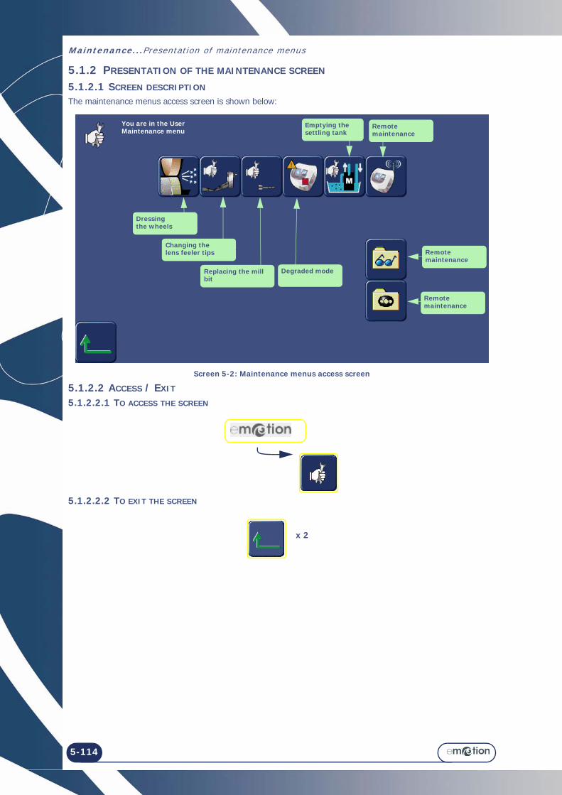
Maintenance...Presentat ion of maintenance menus
5-114
5.1.2 PRESENTATION OF THE MAINTENANCE SCREEN
5.1.2.1 SCREEN DESCRIPTION
The maintenance menus access screen is shown below:
Screen 5-2: Maintenance menus access screen
5.1.2.2 ACCESS / EXIT
5.1.2.2.1 TO ACCESS THE SCREEN
5.1.2.2.2 TO EXIT THE SCREEN
Changing the lens feeler tips
Dressingthe wheels
Replacing the mill bit
Degraded mode
Emptying the settling tank
Remote maintenance
You are in the User Maintenance menu
Remote maintenance
Remote maintenance
x 2

5-115
=> Maintenance
5.2 VISUALISING THE COMPONENTSThe illustrations below will help you to identify the parts of the edger on which you will be working during maintenance operations.
Lens feeler tips> Replacement> Adjustment
Visor> Cleaning and replacement
Lens clamp adaptor pad> Replacement Mill bit
> Replacement> Adjustment

Maintenance...Visual is ing the components
5-116

5-117
=> Maintenance
5.3 TASK LISTTo ensure optimum performance of your emotion, you must carry out a few maintenance operations at regular intervals.Maintenance of the Scanform™ unit → Cleaning the Scanform™ → Replacing a stylus tip → Replacing the frame clip tube → Replacing the centering plateMaintenance of the centering/blocking system zone → Cleaning the ground glass screen → Cleaning the lower lens of the collimator → Replacing the main fuse → Replacing the hand restMaintenance of the touch screen zone → Cleaning the touch screenMaintenance of the Edger → Clean the edger daily with a spray bottle of water. → Replace the flexible lens clamp adaptor pad regularly (every 1000 lenses). → Replace the mill bit when a message asks you to do so (1 hour of total drilling time). → Check the condition of the lens feeler tips regularly and replace them as soon as they appear to be worn or
damaged (or every 3000 lenses). → Dress the wheels when a message asks you to do so. → Clean the removable visor regularly, and replace it if necessary. → Change the water in the tank regularly if your machine operates in closed water circuit mode. → Clean the filters and the tanks regularly. → Check the condition of the safety-beveling and grooving wheels and have them replaced by a technician if
necessary. → Check the condition of the wheels and have them replaced by a technician if necessary.

Maintenance...Task l ist
5-118

Maintenance...Maintenance of the touch screen unit
5-119
5.4 MAINTENANCE OF THE TOUCH SCREEN UNIT5.4.1 CLEANING THE TOUCH SCREEN
CAUTION Do not use products such as water or chemical agents. Ethyl alcohol can be used when a dry cloth is not sufficient enough to remove stubborn stains.The GUARANTEE WILL NOT APPLY to damage caused by improper maintenance of the touch screen.
#1 Switch OFF the emotion if it is ON.
#2 Clean the touch screen gently with a soft, dry lint-free cloth.

Maintenance...Maintenance of the touch screen unit
5-120
Illustration 5-1: Scanform

Maintenance...Maintenance of the Scanform unit
5-121
5.5 MAINTENANCE OF THE SCANFORM UNIT5.5.1 CLEANING THE SCANFORM
To clean the Scanform™, proceed as follows:
5.5.2 REPLACING A STYLUS TIP
To replace a stylus tip, proceed as follows:
#1 Switch OFF the emotion if it is ON..
#2 Lift up the stylus tip manually.
#3 Clean the stylus tip with a brush, making sure no dusts enter the Scanform™ unit.
#4 Gently blow away any dusts from the Scanform™ unit using a compressed air spray.
#1 Switch OFF the emotion if it is ON..
#2 Manually open the Scanform™ and lift up the stylus tip. Hold the elements in this position without applying force.
#3 Place a sheet of paper at the base of the stylus shaft to pevent screws from falling into the Scanform™ then loosen the fixing screws (A) from the stylus tip using an optician screwdriver.
#4 Remove the stylus tip.
#5 Fit a new stylus tip on the shaft.
#6 Attach the stylus tip with the fixing screws.
#7 Release the pressure on the stylus tip and the Scanform™.
#8 Switch on the emotion.
#9 Adjust the Scanform™ (see § Adjusting the Scanform™, chapter Settings & Adjustments).

Maintenance...Maintenance of the Scanform unit
5-122
5.5.3 REPLACING THE FRAME CLIP TUBES
To replace the frame clip tubes, proceed as follows:
5.5.4 REPLACING THE CENTERING PLATE To replace the centering plate, proceed as follows:
#1 Switch OFF the emotion if it is ON.
#2 Manually open the Scanform™ and hold it in this position without applying force.
#3 Pull the concerned frame clip tube horizontally and remove it (Example (Figure 1)).
NOTE: Only the upper frame clip tubes can be replaced.
#4 Fit the new frame clip tube (make sure the tube is engaged fully home in its shaft).
#5 Release the pressure on the Scanform™.
#1 Switch OFF the emotion if it is ON.
#2 Manually open the Scanform™ and hold it in this position without applying force.
#3 Lightly press on the pin of the holding hook (A) (Figure 1) to disengage the centering plate.
#4 Remove the centering plate from its housing.
#5 Fit the new centering plate: Push it down until the holding hook is in position.
#6 Release the pressure on the Scanform™.
A

Maintenance...Maintenance of the Scanform unit
5-123

Maintenance...Maintenance of the Scanform unit
5-124
Illustration 5-1: Centering/blocking system

Maintenance...Maintenance of the centering/blocking system zone
5-125
5.6 MAINTENANCE OF THE CENTERING/BLOCKING SYSTEM ZONE5.6.1 CLEANING THE GROUND GLASS SCREEN
To clean the ground glass screen, proceed as follows:
*CAUTION Avoid contaminating the ground glass screen with greasy substances or your fingers.The alteration of the screen opacity can lead to equipment malfunctions which are NOT COVERED BY THE GUARANTEE.
NOTEIt is recommended to clean the screen with a circular movement from the centre outwards.
5.6.2 CLEANING THE LOWER LENS OF THE COLLIMATOR
To clean the lower lens of the collimator, proceed as follows:
*NOTEIt is recommended to clean the lower lens of the collimator with a circular movement from the centre outwards.
5.6.3 REPLACING THE MAIN FUSE
To replace a fuse, proceed as follows:
CAUTION STRICTLY OBSERVE THE FOLLOWING INSTRUCTIONS. FAILURE TO DO SO CAN BE DANGEROUS BOTH FOR THE USER AND THE MACHINE.
#1 Remove any parts which might interfere with the operation (e.g. lens holder placed on the ground glass screen).
#2 Clean the touch screen gently with a soft, dry lint-free cloth.
#1 Remove any parts which might interfere with the operation (e.g. lens holder placed on the ground glass screen).
#2 Clean the lower lens of the collimator with antistatic cleaning swabs (P/N1000186) (Figure 1).*

Maintenance...Maintenance of the center ing/blocking system zone
5-126
#1 Switch OFF the emotion if it is ON.
#2 Disconnect the power cord from the wall plug.
#3 Remove the fuse from the fuse holder on the left of the emotion mains plug.
#4 Fit a new fuse (see Technical specifications, chapter 7.2) in its housing.
#5 Connect the emotion power cord to the wall plug.
F1
F2
F4F3F6

Maintenance...Regular maintenance of the edger
5-127
5.7 REGULAR MAINTENANCE OF THE EDGER5.7.1 REPLACING THE FLEXIBLE LENS CLAMP ADAPTOR PAD
5.7.1.1 PRELIMINARY REMARKS
Caution! The lens holder adaptor is serrated and the lens feeler tips are pointed. Make sure that your hands are protected when handling the lens holder adaptor and feeler tip.
5.7.1.2 PROCEDURE
To replace the flexible lens clamp adaptor pad, follow the procedure below:
Flow chart 5-1: Replacing the flexible lens clamp adaptor pad
→ As shown...
Illustration 5-1: Replacing the flexible lens clamp adaptor pad
#1
#2
#3 Remove the lens clamp adaptor pad gently from the clamping shaft (on the right).
#4 Remove the used lens clamp adaptor pad and replace it with a new one.
#5 Refit the lens clamp adaptor pad on the clamping shaft.

Maintenance...Regular maintenance of the edger
5-128
Illustration 5-2: Replacing the mill bit
Mill bit
Chuck nut
Spacer
Block the rotation with an Allen key or with one turn of the screwdriver!
Tighten/Loosenthe nut
Flat organic lensDiameter > 57 mm10 00 205
Flushing point
#4 #5-11
#13 #14
#16

Maintenance...Regular maintenance of the edger
5-129
5.7.2 REPLACING THE MILL BIT
5.7.2.1 PRELIMINARY REMARKS
It may be necessary to change the mill bit.A change of mill bit may be necessary for the following reasons: > Broken bit > Worn bit (chips around the holes on the internal side of the lens?) > Excessive use of the bit.
The machine is guaranteed to operate correctly if Briot mill bits are mounted.
5.7.2.2 PROCEDURE
To change the mill bit, follow the procedure below:
#1
#2
#3
#4
#5 Insert an Allen key or a screwdriver in the spacer hole to block the rotation of the spindle.
#6 Fit an 8 mm spanner on the chuck nut.
#7 Loosen the nut with one turn of the spanner, to free the bit.
#8 Use pliers to remove the bit from the chuck.
#9 Fit a new bit in the chuck. We advise you to apply a touch of grease to the end of the bit to ease its insertion into the chuck. Caution! Ensure that the bit is pushed home inside the chuck.
#10 Tighten the chuck nut lightly with the 8 mm spanner to immobilize the mill bit.
#11 When the bit is tightened, remove the Allen key or the screwdriver.
#12

Maintenance...Regular maintenance of the edger
5-130

Maintenance...Regular maintenance of the edger
5-131
Flow chart 5-2: Replacing the mill bit
Note: → The drilling counters are automatically updated. → The new setting position is automatically saved.
5.7.2.3 HINTS
> During step 8, the bit may be difficult to remove from the chuck because of possible scale deposits. In this case apply a small quantity of a common scale remover, leave it for a few moments then remove the bit.
> Use bits supplied by your Briot representative.
#13 Block the adjustment lens 10 00 205 in the centre and fit it on the lens holder shaft.
#14
#15 x 3
#16 Remove the drilled lens from the edging station.

Maintenance...Regular maintenance of the edger
5-132
Illustration 5-3: Replacing the lens feeler tips
FRAGILE MOUNTING!
Removable lens feeler tip
#5,6,7.8
Place the feelers in the replacement position.
Place the feelers in the position to receive the tool.
Confirm and switch automatically to the feeling adjustment screen.
#4
#10
#13

Maintenance...Regular maintenance of the edger
5-133
5.7.3 REPLACING THE LENS FEELER TIPS
5.7.3.1 PRELIMINARY REMARKS
> Always contact your Briot representative before replacing the lens feeler tips.
5.7.3.2 PROCEDURE
To replace the feeler tip, follow the procedure below:
Flow chart 5-3: Replacing the lens feeler tips
#1
#2
#3
#4
#5 Hold the holder and immobilize the feeler arm.
#6 Insert a screwdriver or an Allen key in the hole of the removable feeler tip.
#7 Tilt the right feeler tip carefully to unclip it.
#8 Remove the worn feeler tip and replace it with a new one.
#9
#10 Remove the lens clamping and lens holder adaptors from the shafts.
#11 Fit the setting tool on the shafts.
#12
#13 When the adjustment is finished, remove the tool.
#14 x 3

Maintenance...Regular maintenance of the edger
5-134

Maintenance...Regular maintenance of the edger
5-135
5.7.3.3 HINTS
> When you are handling the feeler tips, do not apply pressure on the feeler arms because that could alter the quality of the work produced by the machine. If you observe any malfunctioning after changing the feeler tips, contact your Briot representative.

Maintenance...Regular maintenance of the edger
5-136
Illustration 5-4: Dressing a wheel
#5
#4
=>
#6Ensure that the dressing disk is correctly centered using the indentations intended to receive the adaptors.

Maintenance...Regular maintenance of the edger
5-137
5.7.4 DRESSING A WHEEL
5.7.4.1 PRELIMINARY REMARKS
> Dressing the polishing wheel is not recommended. > Too frequent dressing of the wheels reduces their working life.
5.7.4.2 PROCEDURE
Follow the steps below to dress a wheel:
Flow chart 5-4: Dressing a wheel
5.7.4.3 HINTS
> Dress the wheels when a message asks you to do so.
#1
#2
#3
#4 OR OR OR
According to your selection
#5 Make sure large adaptors are fitted.
#6 Fit the dressing disc which corresponds to the wheel to be dressed. Make sure it is centered on the lens clamping and lens holder adaptors.
#7
#8 When the adjustment is finished, open the lens clamping shaft while holding the disk and remove the disk.
#9 x 3

Maintenance...Regular maintenance of the edger
5-138
Illustration 5-5: Cleaning and replacing the removable visor
ScrewOuter visor
Inner visor
#1
#2
#3 #5 or #6

Maintenance...Regular maintenance of the edger
5-139
5.7.5 CLEANING / REPLACING THE REMOVABLE VISOR
5.7.5.1 PRELIMINARY REMARKS
> Before undertaking any operation, ensure that the machine is switched off: On/Off switch OFF and mains plug disconnected.
5.7.5.2 REPLACING THE VISOR
5.7.5.2.1 PROCEDURE
To replace the visor, proceed as described above. Only Step 6 changes.
5.7.5.3 HINTS
> Regular cleaning of the visor increases the visibility of the interior of the edging chamber and the operations under way.
> Operating in closed circuit mode affects the cleanliness of the visor. We recommend more frequent cleaning of the visor.
# 6 Insert a new removable visor in the holder.
# 1 Loosen the 4 screws of the outer visor.
# 2 Apply pressure on either side of the visor to unclip it.
# 3 Remove the inner visor using the slide.
# 5 Clean the inner visor then insert it in its holder.
# 7 Tighten the 4 screws of the outer visor.

Maintenance...Regular maintenance of the edger
5-140
Illustration 5-6: Presentation of the tanks
Illustration 5-7: Cleaning the drawer-filter
Illustration 5-8: Complete cleaning of the tanks and filters
Pump tank
Settling tank(also called main tank)
Drawer-filter
Settler
#2#1
#1 #2.3
#4 #5
Dump pipe valve closed

Maintenance...Regular maintenance of the edger
5-141
5.7.6 CLEANING THE FILTERS AND WATER TANK
5.7.6.1 PRELIMINARY REMARKS
> Before undertaking any operation, ensure that the machine is switched off: On/Off switch OFF and mains plug disconnected.
> Cleaning frequency is left to the discretion of the user, according to the number of lenses which have been edged. However, Briot recommends cleaning every 500 lenses (mineral and plastic).
> Gloves and eye shields must be worn. It is advisable to wear an overall. > Ensure that the dump pipe valve is closed before starting the machine - the red handle must be perpendicular
to the T.
5.7.6.2 PROCEDURES
Three situations are possible:
5.7.6.2.1 FOR DAILY CLEANING
Flow chart 5-5: Daily cleaning of the drawer-filter
5.7.6.2.2 COMPLETE CLEANING OF THE TANKS AND FILTERS
#1 Lift the water drain pipe and remove the drawer-filter.
#2 Clean the drawer-filter with a brush.
#3 Clean the drawer-filter.
#4 Refit the drawer-filter.
#1 Empty the settling tank (see “Emptying the water tank”, page 145
#2 Ensure that the dump pipe valve is correctly closed.
#3 Unscrew the water supply pipe from the valve.
#4 Free the drain pipe from the drawer-filter and remove the drawer-filter.
#5 Remove the 2 fixing screws from the pump supporting plate.
#6 Remove the pump supporting plate.
#7 Remove the pump from the pump tank.
#8 Brush the lateral filters of the pump tank.
→ The procedure continues on the next page.

Maintenance...Regular maintenance of the edger
5-142
#8 #9
#13
#14
Pump connected to PUMP socket
Water supply pipe connected to the valve
Drain pipe placed above clean drawer-filter
Dump pipe valve closed

Maintenance...Regular maintenance of the edger
5-143
Flow chart 5-6: Complete cleaning of the settling tank
5.7.6.3 HINTS
> If the pump is not activated when you restart the machine after cleaning, open the discharge valve to the minimum to allow the escape of any air which has remained in the pipes. Close the valve before restarting the process.
> Always check the water-tightness of the unit before restarting the machine. • Check the connections of the drain, water supply and pump pipes.• Ensure that the discharge valve is closed.• If you have worked on the solenoid valves, check the fixings.
#9 Remove the settler carefully.
#10 Clean the settler with a plastic spatula and a brush above the drainage system (bucket, waste bin, drain, etc.).
#11 Clean the settler.
#12 Remove the used plastic bag from the settling tank and dispose of it.
#13 Clean the settling tank if necessary.
#14 Place a new plastic bag in the settling tank.
#15 Reassemble the tanks, pump and pipes.
#16 Fill the water tank to within 6 or 7 cm of the upper edge of the plastic bag.
#17 Run a dummy edging cycle to prime the unit.

Maintenance...Regular maintenance of the edger
5-144
Illustration 5-9: Emptying the settling tank
Illustration 5-10: Water connections
Open/Closethe discharge valve
Example ofdrainage system
Discharge pipe
#1
#5;8
Discharge valveClosed position
Supply connection
Discharge connection

Maintenance...Regular maintenance of the edger
5-145
5.7.7 EMPTYING THE WATER TANK
5.7.7.1 PRELIMINARY REMARKS
> Use a standard discharge pipe with a 20x27 connection.
5.7.7.2 PROCEDURE
To empty the settling tank, follow the procedure below:
Flow chart 5-7: Emptying the settling tank
5.7.7.3 HINTS
> If the pump is not activated when you restart the machine after cleaning, open the discharge valve to the minimum to allow the escape of any air which has remained in the pipes. Close the valve before restarting the process.
> Always check the water-tightness of the unit before restarting the machine. • Check the connections of the drain, water supply and pump pipes.• Ensure that the discharge valve is closed. • Check that all parts are correctly attached, especially the solenoid valves.
#1 Fit a discharge pipe on the same side as the valve and connect it to the drainage system (bucket, sink, drain etc.).
#2
#3
#4
#5
#6 Open the discharge valve.
#7 Close the discharge valve when the settling tank is empty.
#8
#9 x 3
#10 Disconnect the discharge pipe and put it away.

Maintenance...Regular maintenance of the edger
5-146

Maintenance...Handling the covers
5-147
5.8 HANDLING THE COVERS5.8.1 REMOVING THE COVERS
5.8.1.1 WHEN? > The machine is clamped during transport to ensure maximum stability. To reach the clamping screws, the
machine covers must be taken off by a technician.
5.8.1.2 HOW?To remove the machine covers, follow the procedure below:
Flow chart 5-8: Removing the covers → As shown...
Illustration 5-11: Removing the covers
5.8.2 REPLACING THE COVERS
To replace the machine covers, follow the above procedure in reverse order.
#1 Loosen and remove the four fixing screws from the upper cover and remove the cover.
#2 Loosen and remove the four fixing screws from the rear cover and remove the cover.
#3 Loosen and remove the four fixing screws from the Scanform cover and remove the cover.
#4 Loosen and remove the four fixing screws from the front cover and remove the cover.
2 screws
4 screws
5 screws
Upper cover
Front cover
Scanform cover
Rear cover
3 screws
4 screws

Maintenance...Handl ing the covers
5-148

Maintenance...Preventive maintenance
5-149
5.9 PREVENTIVE MAINTENANCE5.9.1 HINTS
> You will optimize the working life of your edger by using only Briot spare parts. > Change the blocks regularly - every 100 lenses.
5.9.2 REPLACEMENT TABLE FOR STANDARD PARTS
The following table summarizes the replacement frequency for standard parts, calculated according to the number of lenses edged.
TABLE 1: REPLACEMENT OF STANDARD PARTS
Part Briot Part Number Number of lenses edged
Briot block - Large Size(25 mm diameter)
21 53 012 Every 100 lenses.
Briot block - Small Size(19 mm diameter)
21 53 013 Every 100 lenses.
Briot block - 17 across flats 11 53 034 Every 100 lenses.
Flexiible lens clamp adaptor pad - Large size
11 38 162 Every 1000 lenses.
Flexible lens clamp adaptor pad - Small Size
11 38 161 Every 1000 lenses.
Flexible lens clamp adaptor pad - 17 across flats
11 38 171 Every 1000 lenses.
Removable lens feeler tip 11 38 201 Every 3000 lenses.
Lens holder adaptor - Large Size 11 90 375 If necessary
Lens holder adaptor - Small Size 11 90 406 If necessary
Lens holder adaptor - 17 across flats 11 90 522 If necessary
Mineral roughing wheel Replaced by a Briot technician only
15 47 117 Every 10000 lenses.
TPT wheelReplaced by a Briot technician only
15 47 131 Every 50000 lenses.
Finishing wheelReplaced by a Briot technician only
15 77 411 Every 8000 lenses.
Polishing wheelReplaced by a Briot technician only
15 77 415 Every 6000 lenses.
Safety-Bevel wheelReplaced by a Briot technician only
16 06 207 Every 50000 lenses, per wheel side
Grooving wheelReplaced by a Briot technician only
16 06 304 Every 5000 lenses.
Mill bit 14 06 504 1 hr of total drilling
Emptying the settling tank (if closed circuit operation)Cleaning of tanks and filters
- Every 500 lenses.
Visor 11 97 050 If necessary
Filter seal 20x27 21 62 153 If necessary

Maintenance...Prevent ive maintenance
5-150

Maintenance...Adjustments
5-151
5.10 ADJUSTMENTS5.10.1 PRESENTATION OF THE SETTINGS MENUS ACCESS SCREEN
5.10.1.1 SCREEN DESCRIPTION
The settings menus access screen is shown below:
Screen 5-3: Setting menus access screen
5.10.1.2 ACCESS / EXIT
5.10.1.2.1 TO ACCESS THE SCREEN
5.10.1.2.2TO EXIT THE SCREEN
Touch screen adjustment
You are in the User Settings menu
Consultation of setting values
Feeling adjustment
Scanform adjustment
Mineral roughing wheel adjustment
Size adjustment
Axis adjustment
The machine restarts.
x 2

Maintenance...Adjustments
5-152
5.10.2 ADJUSTING THE SCANFORM
To adjust the Scanform™, proceed as follows:
#1 Press on the top of the application screen. Result: The menus access screen is displayed.
#2 Press this key
#3 Press this key: Result: The Scanform™ starts operating .
#4 The icon is displayed. Get the gain adjustment tool No. 14 04 218 .
#5 Ensure that the R and H values marked on the tool are the same as those displayed on the screen. If the values are the same, go to the next step. If the values are not the same, enter the values marked on
the tool using the keys and . Note: The R value should be around 40 mm and the H value around 24 mm.
#6 Position the tool in the Scanform™ .
#7 Press to start the adjustment.
#8 When the adjustment is finished, check the measured valued which are displayed on the screen. Adjustment is correct when all the dots in front of the parameters are green. Note: If one or more dots are red, repeat the step by pressing the
key. If the problem cannot be solved, please contact your distributor.
#9 Remove the tool.
Press . Result: The emotion validates this adjustment and proceeds to the next one.

Maintenance...Adjustments
5-153
#10 When the icon is displayed, get the tool No. 14 04 185.
#11 Ensure that the diameter value of the round shape marked on the tool is the same as the value displayed on the screen. If the values are the same, go to the next step. If the values are not the same, enter the values marked on the tool using the following key:
Note: The value should be around 40 mm.
#12 Position the tool in the frame-holder (Figure 2).
#13 Press . Result: The sylus is inserted in the tool and adjustment is started.
#14 When the adjustment is finished, check the measured valued which are displayed on the screen. Adjustment is correct when all the dots in front of the parameters are green. Note: If one or more dots are red, repeat the step by pressing the
key. If the problem cannot be solved, please contact your distributor.
#15 Remove the tool.
#16 Press . Result: The emotion validates this adjustment and proceeds to the next one.
#17 When the icon is displayed, insert the round pattern No. 14 04 192 on the pattern holder.
#18 Ensure that the diameter value of the pattern marked on the tool No. 14 04 192 is the same as the value displayed on the screen. If the values are the same, go to the next step. If the values are not the same, enter the values marked on the tool using the following key:
Note: The value should be around 40 mm.

Maintenance...Adjustments
5-154
#19 Position the tool in the frame-holder (Figure 3).
Figure 3
#20 Press . Result: The sylus grabs the round pattern and adjustment is started.
#21 When the adjustment is finished, check the measured values which are displayed on the screen. Adjustment is correct when all the dots in front of the parameters are green. Note: If one or more dots are red, repeat the step by pressing the
key. If the problem cannot be solved, please contact your distributor.
#22 Remove the tool.
#23 Press . Result: The emotion validates this adjustment and proceeds to the next one.
#24 When the icon is displayed, insert the rectangular pattern No. 14 04 191 on the pattern holder.
#25 Position the tool in the frame-holder (Figure 4).
Figure 4
#26 Press . Result: The sylus grabs the round pattern and adjustment is started.
#27 When the adjustment is finished, check the measured values which are displayed on the screen. Adjustment is correct when all the dots in front of the parameters are green. Note: If one or more dots are red, repeat the step by pressing the
key. If the problem cannot be solved, please contact your distributor.
#28 Remove the tool.
#29 Press . Result: The emotion validates this adjustment and the settings access screen is displayed.
#30 Press to leave the settings access screen.

Maintenance...Adjustments
5-155

Maintenance...Adjustments
5-156
Screen 5-4: Feeling adjustment

Maintenance...Adjustments
5-157
5.10.3 ADJUSTING THE FEELING
5.10.3.1 WHEN? > If a message asks you to do so. > If you observe that the feeler tips are beginning to be worn. > After replacing the feeler tips - the machine then switches automatically to this screen.
5.10.3.2 PROCEDURE
Follow the steps below to adjust the feeling:
Flow chart 5-9: Feeling adjustment
5.10.3.3 HINTS
> Always check that the setting tool 14 04 199 is correctly fitted on the shaft. You must neither force the fitting or feel any play.
> The feeling setting can be incorrect if the tool is badly positioned. This factor also affects the quality of the work produced by the machine.
#1
#2
#3
#4 Remove the lens clamping and lens holder adaptors from the shafts.
#5 Fit the setting tool on the shafts.
#6
#7 When the adjustment is finished, remove the tool.
#8 Refit the lens holder and lens clamping adaptors.
#9 x 3

Maintenance...Adjustments
5-158
Screen 5-5: Adjusting the sizes - Screen 1

Maintenance...Adjustments
5-159
5.10.4 ADJUSTING THE SIZES
5.10.4.1 WHEN? > Perform this adjustment regularly. The wear of the wheels has a direct influence on the lens sizes, which
increases over time. This will help you to avoid retouch. > Centre the adjustment lens 10 00 205 exactly in the centre so as to be able to use it from start to finish size
adjustment. > When you measure the lens size with a digital caliper, keep the lens in the same plan as the caliper. Take
two consecutive measurements 90° apart and record the average value with the numeric keypad. > Perform the size adjustment procedure from beginning to end so as to record all the parameters.
5.10.4.2 PROCEDURE
Follow the steps below to adjust sizes:
#1
#2
#3
#4 Make sure the 25 mm adaptors are fitted.
#5 Block a lens 10 00 205 in the centre and fit it on the lens holder shaft .
#6
#7 At the end of the edging process, open the lens holder shaft and remove the lens.
#8 Measure the size of the lens with a caliper.
#9
#10 Enter the value using the numeric key pad.
#11
#12 OR
Repeat the edging process > Lens edged to 55 mm diameter - Rimless finishing
> Lens edged to 57.5 mm diameter - Rimless finishing
Follow the usual procedure

Maintenance...Adjustments
5-160
#13 Fit the lens on the lens holder shaft again.
#14
#15 At the end of the edging process, open the lens holder shaft and remove the lens.
#16 Measure the size of the lens with a caliper.
#17
#18 Enter the value using the numeric key pad.
#19
#20 Check the position of the apex of the bevel with a linen-counter. The apex must be in the centre of the edge of the lens.
#21
#22 If the apex of the bevel is off-centered, enter the value of the shift using the numeric key pad.• Apex too close to the rear face => enter a negative value• Apex too close to the front face => enter a positive value
#23
#24 OR
#25 Fit the lens on the lens holder shaft again.
#26
#27 At the end of the edging process, open the lens holder shaft and remove the lens.
Repeat the edging process > Lens edged to 47.5 mm diameter - Bevel finishing
Follow theusual procedure
> Lens edged to 50 mm diameter - Bevel finishing
> Lens edged to 42.5 mm diameter - Rimless finishing and polishing
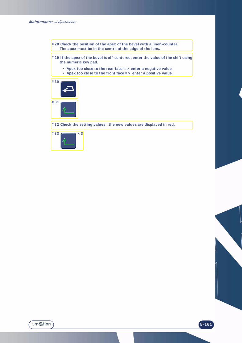
Maintenance...Adjustments
5-161
#28 Check the position of the apex of the bevel with a linen-counter. The apex must be in the centre of the edge of the lens.
#29 If the apex of the bevel is off-centered, enter the value of the shift using the numeric key pad.
• Apex too close to the rear face => enter a negative value• Apex too close to the front face => enter a positive value
#30
#31
#32 Check the setting values ; the new values are displayed in red.
#33 x 3

Maintenance...Adjustments
5-162
Screen 5-6: Adjustment of the flush of the mill bit

Maintenance...Adjustments
5-163
5.10.5 ADJUSTING THE FLUSH OF THE MILL BIT
5.10.5.1 WHEN? > When you observe an error in the position or the depth of the drilling holes produced by the machine. > After replacing the mill bit - the machine then switches automatically to this screen.
5.10.5.2 PROCEDURE
To adjust the mill bit flush, proceed as follows:
Flow chart 5-10: Adjusting the flush of the mill bit
5.10.5.3 HINTS
> Centre the lens 10 00 205 in the centre so as to be able to use it from start to finish of mill bit flush adjustment.
#1
#2
#3
#4 Block the adjustment lens 10 00 205 in the centre and fit it on the lens holder shaft.
#5
#6 At the end of the adjustment process, open the shafts and remove the lens.
#7 x 3

Maintenance...Adjustments
5-164
Screen 5-7: Adjustment of the touch screen

Maintenance...Adjustments
5-165
5.10.6 ADJUSTING THE TOUCH SCREEN
5.10.6.1 WHEN?The machine switches automatically to this screen when the touch screen has not been detected.When you observe a difference between the displayed icon and the touch area of the screen.
5.10.6.2 PROCEDURE
Follow the steps below to adjust the touch screen:
Flow chart 5-11: Adjustment of the touch screen
5.10.6.3 HINTS
> Make sure that you press carefully on the crosses being adjusted. Otherwise you may affect the touch screen settings.
> If you think you have not pressed on a cross correctly, wait a few moments. The adjustment becomes accessible again after 5 seconds.
#1
#2
#3
#4 Press carefully on the red crosses which are displayed successively.
#5 x 3

Maintenance...Adjustments
5-166
Screen 5-8: Example of a setting values display screen

Maintenance...Adjustments
5-167
5.10.7 CONSULTING THE SETTING VALUES
5.10.7.1 PRESENTATION
> A hotline technician may ask you for some setting values, in order to diagnose a possible problem for example.
> The setting values cannot be modified from these screens.
5.10.7.2 ACCESS/EXIT/NAVIGATION
5.10.7.2.1 TO ACCESS THE SCREENS
5.10.7.2.2 TO EXIT THE SCREENS
5.10.7.2.3 TO NAVIGATE FROM ONE SCREEN TO ANOTHER
> To go to the following screen:
> To go to the previous screen:
5.10.7.3 PRESENTATION OF THE SETTING VALUE SCREENS
Refer to the next screen, which is typical of the 12 user screens.
x 2

Maintenance...Adjustments
5-168
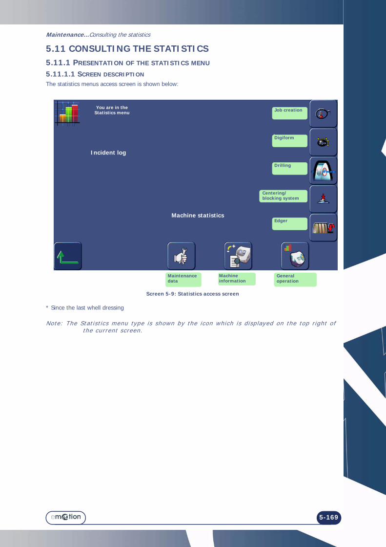
Maintenance...Consulting the statistics
5-169
5.11 CONSULTING THE STATISTICS5.11.1 PRESENTATION OF THE STATISTICS MENU
5.11.1.1 SCREEN DESCRIPTION
The statistics menus access screen is shown below:
Screen 5-9: Statistics access screen
* Since the last whell dressing
Note: The Stat ist ics menu type is shown by the icon which is displayed on the top r ight of the current screen.
Incident log
Machine statistics
You are in the Statistics menu Job creation
General operation
Machine information
Maintenance data
Digiform
Drilling
Centering/blocking system
Edger

Maintenance...Consult ing the stat ist ics
5-170
5.11.1.2 ACCESS/EXIT
5.11.1.2.1 TO ACCESS THE SCREEN
5.11.1.2.2 TO EXIT THE SCREEN
5.11.2 CONSULTATION PRINCIPLES
The statistics relate to two types of information:• Displayed messages, or incident log• The machine's general operation.
The screens associated with each type of information have different operating principles, as described below:
5.11.2.1 INCIDENT LOG
5.11.2.1.1 CONTENT
The incident log may be consulted according to four themes: → Consultation of the general list of incidents which have occurred (incidents, warnings and information) → Consultation of the list of fault messages displayed → Consultation of the list of warning messages displayed → Consultation of the list of information messages displayed.
5.11.2.1.2 ACCESS/EXIT
You may access the desired statistics using the buttons shown above in the paragraph "Presentation of statistics menu".
Exit each menu by pressing the button.
5.11.2.1.3 OPERATION
Each button of the Statistics menu related to the incident log allows two possibilities:

Maintenance...Consulting the statistics
5-171
→ Consultation of the last 128 incidents listed according to their order of appearance: SCREEN
Screen 5-10: Consultation of the incidents listed according to their order of appearance:
→ Consultation of the 10 most recent incidents listed according to their occurrences.
Screen 5-11: Consultation of the incidents listed according to their occurrences:
You are in the General List menu
Incident 127 is the most recent; It occurred on lens 646 and is of type M0 - I48.
<= To exit
Scroll down and consult the incidents from the oldest to the most recent.
Go to the screen showing the incidents listed according to their occurrences.
For more information about an incident, press the corresponding line.=> The message is then displayed.
The list shows the 128 messages displayed since the last update, in descending order from the most recent.
128 messages may be memorised and displayed by groups of 10 per page.
Exit
128 incidents
Go to the screen showing the incidents listed in chronological order
Scroll down and consult the incident list from the most frequent.
You are in the General List menu
For more information about an incident, press the corresponding line.=> The message is then displayed.
The list shows the 10 messages displayed since the last update, in descending order from the most frequent.
10 messages may be memorised and displayed.
The most frequent incident occurred 29 times on the M0 - I48 incident.
Exit
10 incidents

Maintenance...Consult ing the stat ist ics
5-172

Maintenance...Consulting the statistics
5-173
5.11.2.2 GENERAL OPERATION OF THE MACHINE
5.11.2.2.1 CONTENT
The statistics related to the general operation of the machine allow you to consult: → Statistics based on jobs → Statistics based on digiforms → Statistics based on drilling → Statistics based on edging → Statistics based on the operation of the machine itself → Statistics based on the last wheel dressing → Statistics based on lens material → Statistics based on bevel and rimless finishing → Statistics based on polishing → Statistics based on safety-bevel → Statistics based on groove finishing → Statistics based on retouch → Statistics based on user maintenance
5.11.2.2.2 ACCESS/EXIT
You may access the desired statistics using the buttons shown above in the paragraph "Presentation of statistics menu".
Exit each menu by pressing the button.
5.11.2.2.3 DESCRIPTION
5.11.2.2.3.1 Edger statistics access screen
Retouch
Polishing Front and rear face
Lens material
Time
Bevel
Grooving
Rimless
Drilling
Drilled hole
Statistics menu
Edging menu
Exit

Maintenance...Consult ing the stat ist ics
5-174
5.11.2.2.3.2 Edger general statistics display screenThe display screen for the edger general statistics is shown below:
Screen 5-12: Consulting the edger general statistics screen
Number of machine starts
ScanformYou are in the Machine Statistics menu
Digiform
Centering/Blocking system
Edging Server communication
Number of Digiform saved operations
Number of OMA saved operations
Number of saved operations with the bar code reader
Exit
OMA communication

Maintenance...Consulting the statistics
5-175
5.11.2.2.3.3 Display screen for statistics based on the last wheel dressing The display screen for statistics based on the last wheel dressing is shown below:
Screen 5-14: Consulting statistics based on the last wheel dressing
Number of mineral lenses edged with bevel finishing
Number of mineral lenses edged with rimless finishing
Number of mineral lenses roughed
Number of lenses edged since the last wheel change
Exit
Statistics based on the last wheel
dressing
Screen 5-13: Dressing maintenance screen
Dressing of 4th disc
Dressing of 2nd disc
Exit

Maintenance...Consult ing the stat ist ics
5-176
5.11.2.2.3.4 Display screen for statistics based on the type of lens materialThe display screen for statistics based on the type of lens material is shown below:
Screen 5-15: Display screen for statistics based on the type of lens material5.11.2.2.3.5 Display screen for statistics based on bevel finishingThe display screen for statistics based on finishing is shown below:
Screen 5-16: Consulting statistics based on finishing
Subject of the statistics
Exit
Subject of the statistics
Exit

Maintenance...Consulting the statistics
5-177
5.11.2.2.3.6 Display screen for statistics based on polishingThe display screen for statistics based on polishing is shown below:
Screen 5-17: Consulting statistics based on polishing
Example: As shown in the above screen:
2 lenses with bevel finishing and polishing have been edged since the machine installation with the wheel currently fitted; The average edging time is 40 seconds per lens.
5 lenses with rimless finishing and polishing have been edged since the machine installation with the wheel currently fitted; The average edging time is 33 seconds per lens.
Subject of the statistics
Total number of lenses edged since the machine installation
Number of lenses edged since the last wheel change
Average edging time
Exit
Statistics based on polishing

Maintenance...Consult ing the stat ist ics
5-178
5.11.2.2.3.7 Display screen for statistics based on safety-bevelThe display screen for statistics based on safety-bevel is shown below:
Screen 5-18: Consulting statistics based on safety-bevel5.11.2.2.3.8 Display screen for statistics based on groove finishingThe display screen for statistics based on groove finishing is shown below:
Screen 5-19: Consulting statistics based on groove finishing
Subject of the statistics
Exit
Subject of the statistics
Exit

Maintenance...Consulting the statistics
5-179
5.11.2.2.3.9 Display screen for statistics based on drilling finishingThe display screen for statistics based on drilling finishing is shown below:
Screen 5-20: Consulting statistics based on drilling finishing
5.11.2.2.3.10Display screen for statistics based on the number of retouchesThe display screen for statistics based on the number of retouches is shown below:
Screen 5-21: Consulting statistics based on retouch
Drilled lenses Drilled holes
Subject of the statistics
Exit
Statistics based onretouches
Lens type
Exit

Maintenance...Consult ing the stat ist ics
5-180
5.11.2.2.3.11Display screen for statistics based on user maintenanceThe display screen for statistics based on user maintenance is shown below:
Screen 5-22: Consulting statistics based on user maintenance
Number of replaced mill bits
Number of replaced feeler tips
Number of dressing operations for the finishing wheel
Number of dressing operations for the chamfering and
mineral wheel
Statistics based on
user maintenance
Exit

Maintenance...Consulting the statistics
5-181
5.11.2.2.3.12Display screen for statistics based on Digiform
Screen 5-23: Consulting statistics based on Digiform
5.11.2.2.3.13Display screen for drilling statistics
Screen 5-24: Consulting drilling statistics
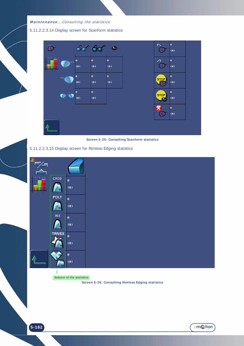
Maintenance...Consult ing the stat ist ics
5-182
5.11.2.2.3.14 Display screen for Scanform statistics
Screen 5-25: Consulting Scanform statistics
5.11.2.2.3.15 Display screen for Rimless Edging statistics
Screen 5-26: Consulting Rimless Edging statisticsSubject of the statistics

Maintenance...Consulting the statistics
5-183
5.11.2.2.3.16 Display screen for Edging, Drilling and Grooving statistics
Screen 5-27: Consulting Edging, Drilling and Grooving statistics
5.11.2.2.3.17 Display screen for time statistics
Screen 5-28: Consulting time statistics
Subject of the statistics
Subject of the statistics

Maintenance...Consult ing the stat ist ics
5-184
5.11.2.2.3.18Display screen for the centering/blocking system statistics
Screen 5-29: Consulting the centering/blocking system statistics5.11.2.2.3.19Display screen for settings statistics
Screen 5-30: Consulting settings statistics

Maintenance...Messages
5-185
5.12MESSAGES5.12.1TYPES OF MESSAGES
There are three types of messages: > Information messages > Warning messages > Fault messages
5.12.2LIST OF MESSAGES.The table below shows all the messages, the conditions for their display and the action to undertake.
# Message Condition(s) for display Action(s)
0x0 Grooving & drilling not allowed on mineral lens.
Mineral lens material can neither be grooved or drilled.
Adapt your job to Mineral lens material: bevel or rimless finishingor Use another lens material for the current job.
0x1 Edging parameters incomplete.
You have started edging before selecting all the parameters.
Check that all parameters have been selected.No "To be defined" button must be visible!
0x2 Please select a job. You have started edging without first loading a shape.
Load a shape, select the parameters then start the edging process.
0x4 Edging in progress. Job A is in progress and you have called up job B.
Wait until the end of the job in progress before loading another job.
0x5 Unknown job number. The job you are trying to load does not exist on the server.
Check the job number and load another number.
0x7 Do you want to re-edge the same lens ?
You have just edged a lens and then re-started a cycle on the same job number and the same side.
YES: If you wish to edge the same lens again or if you wish to edge several lenses with the same parameters.NO: Fit a new lens and proceed as you wish.
0x8 Please waitduring machine shut down.
You have pressed for more than 6 seconds on the machine standby button.
Wait until the machine has stopped before switching off.
0x9 You can safely turn off your machine.
You have asked for the machine to stop. The close-down procedure has been followed. The machine can now be switched off.
Switch off the machine (On/Off button pressed-in and unlit).
0xA Incompatible edger configuration.Trivex lens not allowed.
The job you have loaded calls for Trivex® lens material. In the personalisation menus, you have excluded this parameter.Therefore the edger cannot accept this job.
Confirm the message.If you wish to load this job nonetheless, change the personalisation of the pull-down menus.Select Trivex® lens material.Load the job again.

Maintenance...Messages
5-186
0xB Incompatible edger configuration.HI lens not allowed.
The job you have loaded calls for High Index (HI) lens material. In the personalisation menus, you have excluded this parameter.Therefore the edger cannot accept this job.
Confirm the message.If you wish to load this job nonetheless, change the personalisation of the pull-down menus.Select High Index (HI) lens material.Load the job again.
0xC Incompatible edger configuration.Mineral lens not allowed.
The job you have loaded calls for Mineral lens material. In the personalisation menus, you have excluded this parameter.Therefore the edger cannot accept this job.
Confirm the message.If you wish to load this job nonetheless, change the personalisation of the pull-down menus.Select Mineral lens material.Load the job again.
0xD Incompatible edger configuration.Organic lens not allowed.
The job you have loaded calls for CR39 lens material. In the personalisation menus, you have excluded this parameter.Therefore the edger cannot accept this job.
Confirm the message.If you wish to load this job nonetheless, change the personalisation of the pull-down menus.Select CR39 lens material.Load the job again.
0xE Incompatible edger configuration.Polycarbonate lens not allowed.
The job you have loaded calls for Polycarbonate lens material. In the personalisation menus, you have excluded this parameter.Therefore the edger cannot accept this job.
Confirm the message.If you wish to load this job nonetheless, change the personalisation of the pull-down menus.Select Polycarbonate lens material.Load the job again.
0xF Incompatible edger configuration.Bevel finishing not allowed.
The job you have loaded calls for Bevel finishing. In the personalisation menus, you have excluded this parameter.Therefore the edger cannot accept this job.
Confirm the message.If you wish to load this job nonetheless, change the personalisation of the pull-down menus.Select Bevel finishing.Load the job again.
0x10 Incompatible edger configuration.Rimless finishing not allowed.
The job you have loaded calls for Rimless finishing. In the personalisation menus, you have excluded this parameter.Therefore the edger cannot accept this job.
Confirm the message.If you wish to load this job nonetheless, change the personalisation of the pull-down menus.Select Rimless finishing.Load the job again.
0x11 Incompatible edger configuration.Groove finishing not allowed.
The job you have loaded calls for Groove finishing. In the personalisation menus, you have excluded this parameter.Therefore the edger cannot accept this job.
Confirm the message.If you wish to load this job nonetheless, change the personalisation of the pull-down menus.Select Groove finishing.Load the job again.
# Message Condition(s) for display Action(s)

Maintenance...Messages
5-187
0x12 Incompatible edger configuration.Drilling finishing not allowed.
The job you have loaded calls for Drilling finishing. In the personalisation menus, you have excluded this parameter.Therefore the edger cannot accept this job.
Confirm the message.If you wish to load this job nonetheless, change the personalisation of the pull-down menus.Select Drilling finishing.Load the job again.
0x13 Incompatible edger configuration.Grooving/drilling finishing not allowed.
The job you have loaded calls for Grooving/Drilling finishing. In the personalisation menus, you have excluded this parameter.Therefore the edger cannot accept this job.
Confirm the message.If you wish to load this job nonetheless, change the personalisation of the pull-down menus.Select Grooving/Drilling finishing.Load the job again.
0x14 Incompatible edger configuration.Automatic Bevel sub-finishing not allowed.
The job you have loaded calls for Automatic Bevel sub-finishing. In the personalisation menus, you have excluded this parameter.Therefore the edger cannot accept this job.
Confirm the message.If you wish to load this job nonetheless, change the personalisation of the pull-down menus.Select Automatic bevel sub-finishing.Load the job again.
0x15 Incompatible edger configuration.Bevel curve sub-finishing not allowed.
The job you have loaded calls for Bevel curve sub-finishing. In the personalisation menus, you have excluded this parameter.Therefore the edger cannot accept this job.
Confirm the message.If you wish to load this job nonetheless, change the personalisation of the pull-down menus.Select Bevel curve sub-finishing.Load the job again.
0x16 Incompatible edger configuration.Bevel distance (in mm) sub-finishing not allowed.
The job you have loaded calls for Bevel distance (in mm) sub-finishing. In the personalisation menus, you have excluded this parameter.Therefore the edger cannot accept this job.
Confirm the message.If you wish to load this job nonetheless, change the personalisation of the pull-down menus.Select Bevel distance (in mm) sub-finishing.Load the job again.
0x17 Incompatible edger configuration.Percent bevel sub-finishing not allowed.
The job you have loaded calls for Percent bevel sub-finishing. In the personalisation menus, you have excluded this parameter.Therefore the edger cannot accept this job.
Confirm the message.If you wish to load this job nonetheless, change the personalisation of the pull-down menus.Select Percent bevel sub-finishing.Load the job again.
0x18 Incompatible edger configuration.Manual bevel sub-finishing not allowed.
The job you have loaded calls for Manual bevel sub-finishing. In the personalisation menus, you have excluded this parameter.Therefore the edger cannot accept this job.
Confirm the message.If you wish to load this job nonetheless, change the personalisation of the pull-down menus.Select Manual bevel sub-finishing.Load the job again.
# Message Condition(s) for display Action(s)

Maintenance...Messages
5-188
0x19 Incompatible edger configuration.Automatic groove sub-finishing not allowed.
The job you have loaded calls for Automatic groove sub-finishing. In the personalisation menus, you have excluded this parameter.Therefore the edger cannot accept this job.
Confirm the message.If you wish to load this job nonetheless, change the personalisation of the pull-down menus.Select Automatic groove sub-finishing.Load the job again.
0x1A Incompatible edger configuration.Automatic groove sub-finishing not allowed.
The job you have loaded calls for Groove Curve sub-finishing. In the personalisation menus, you have excluded this parameter.Therefore the edger cannot accept this job.
Confirm the message.If you wish to load this job nonetheless, change the personalisation of the pull-down menus.Select Groove curve sub-finishing.Load the job again.
0x1B Incompatible edger configuration.Front groove distance (in mm) sub-finishing not allowed.
The job you have loaded calls for Front groove distance (in mm) sub-finishing. In the personalisation menus, you have excluded this parameter.Therefore the edger cannot accept this job.
Confirm the message.If you wish to load this job nonetheless, change the personalisation of the pull-down menus.Select Front groove distance (in mm) sub-finishing.Load the job again.
0x1C Incompatible edger configuration.Percent groove sub-finishing not allowed.
The job you have loaded calls for Percent groove sub-finishing.In the personalisation menus, you have excluded this parameter.Therefore the edger cannot accept this job.
Confirm the message.If you wish to load this job nonetheless, change the personalisation of the pull-down menus.Select Percent groove sub-finishing.Load the job again.
0x1D Incompatible edger configuration.Manual groove sub-finishing not allowed.
The job you have loaded calls for Manual groove sub-finishing. In the personalisation menus, you have excluded this parameter.Therefore the edger cannot accept this job.
Confirm the message.If you wish to load this job nonetheless, change the personalisation of the pull-down menus.Select Manual groove sub-finishing.Load the job again.
0x1E Incompatible edger configuration.Drilling normal to rear face not allowed.
The job you have loaded calls for Drilling normal to rear face. In the personalisation menus, you have excluded this parameter.Therefore the edger cannot accept this job.
Confirm the message.If you wish to load this job nonetheless, change the personalisation of the pull-down menus.Select Drilling normal to rear face sub-finishing. Load the job again.
# Message Condition(s) for display Action(s)

Maintenance...Messages
5-189
0x1F Incompatible edger configuration.Drilling normal to front face not allowed.
The job you have loaded calls for Drilling normal to front face. In the personalisation menus, you have excluded this parameter.Therefore the edger cannot accept this job.
Confirm the message.If you wish to load this job nonetheless, change the personalisation of the pull-down menus.Select Drilling normal to front face sub-finishing.Load the job again.
0x20 Incompatible edger configuration.Drilling parallel to clamp shaft not allowed.
The job you have loaded calls for Drilling parallel to clamp shaft.In the personalisation menus, you have excluded this parameter.Therefore the edger cannot accept this job.
Confirm the message.If you wish to load this job nonetheless, change the personalisation of the pull-down menus.Select Drilling parallel to clamp shaft.Load the job again.
0x21 Incompatible edger configuration.Front safety-bevel not allowed.
The job you have loaded calls for front safety-bevel. In the personalisation menus, you have excluded this parameter.Therefore the edger cannot accept this job.
Confirm the message.If you wish to load this job nonetheless, change the personalisation of the pull-down menus.Select Front safety-bevel parameter.Load the job again.
0x22 Incompatible edger configuration.Rear safety-bevel not allowed.
The job you have loaded calls for rear safety-bevel. In the personalisation menus, you have excluded this parameter.Therefore the edger cannot accept this job.
Confirm the message.If you wish to load this job nonetheless, change the personalisation of the pull-down menus.Select Rear safety-bevel parameter.Load the job again.
0x23 Incompatible edger configuration.Front and rear safety-bevel not allowed.
The job you have loaded calls for front and rear safety-bevels. In the personalisation menus, you have excluded this parameter.Therefore the edger cannot accept this job.
Confirm the message.If you wish to load this job nonetheless, change the personalisation of the pull-down menus.Select Front and rear safety-bevel parameter.Load the job again.
0x24 Incompatible edger configuration.Lens without safety-bevel not allowed.
The job you have loaded has the No safety-bevel parameter. In the personalisation menus, you have excluded this parameter.Therefore the edger cannot accept this job.
Confirm the message.If you wish to load this job nonetheless, change the personalisation of the pull-down menus.Select the No safety-bevel parameter.Load the job again.
# Message Condition(s) for display Action(s)

Maintenance...Messages
5-190
0x25 Incompatible edger configuration.Safety-bevel to be defined not allowed.
The job you have loaded has the parameter Safety-bevel to be defined. In the personalisation menus, you have excluded this parameter.Therefore the edger cannot accept this job.
Confirm the message.If you wish to load this job nonetheless, change the personalisation of the pull-down menus.Select the Safety-bevel to be defined parameter.Load the job again.
0x26 Retouch impossible on drilled or grooved lens.
You wish to undertake a retouch on a lens which has been drilled or grooved. This operation is impossible on a lens with these finishes.
Carry out the lens size adjustment procedure. Fit a new lens and enter a negative oversize value.
0x2B Wrong job received. Problems of communication with the server have been detected.
Load another job number
0x30 Do you want to save the new personalisation?
At least one of the parameters of the menus personalisation has changed. The machine requests confirmation of this modification.
Confirm: the new personalisation is registered.No confirmation: the new personalisation is not registered. The previous personalisation is retained.Cancel: you return to the personalisation screen for the menu-button concerned. Reselect the elements you wish to display.
0x34 Groove too near front. The distance between the front face of the lens and the external edge of the groove is less than 0.2 mm.
Confirm the message.Select Manual Groove sub-finishing.Visualise the position of the groove on the control screen.Reposition the groove.
0x35 Groove too far back. The distance between the rear face of the lens and the internal edge of the groove is less than 0.2 mm.
Confirm the message.Select Manual Groove sub-finishing.Visualise the position of the groove on the control screen.Reposition the groove.
0x100 Requested job does not exist.
You have called up a job number but the corresponding job is not on the server.
Call up another number.
0x101 No response from server within time limit.
You have tried to load a job but the edger has not received a signal from the server.
Check that:- The server is switched on.- The OMA cord is correctly connected to both terminals.Then load the job again.
0x102 The server is switched off. The OMA cord is disconnected.ORThe server is switched off.
Check that:- The server is switched on.- The OMA cord is correctly connected to both terminals.Then load the job again.
# Message Condition(s) for display Action(s)

Maintenance...Messages
5-191
0x103 Corrupt OMA frame. The OMA frame sent by the server displays a fault which princidents reception.
Contact a Briot technician.
0x104 Invalid OMA frame. The OMA frame sent by the server displays parameters which the edger does not recognize.
Contact a Briot technician.
0x300 Touch screen not detected. When the edger is initialised, the touch screen is not detected.
Contact a Briot technician.
0x404 Safety-Bevel or Grooving impossible.
Safety-bevel and/or groove cannot be made.
Confirm the message.Select new parameters.
0x405 Holes deleted (at least one was unfeasible). Do you want to continue?
The drilling plan includes at least one hole positioned too close to the block or too far from the edge of the lens.
YES: the lens is edged but not drilled. Then you can produce the holes with a drill.NO: the lens is not edged. Remove the lens from the edging station.
0x406 External safety-bevel will not be made.Do you want to continue?
External safety-bevel cannot be made.The lens is too thin and/or the shape is too small.
YES: the lens is edged without an external safety-bevel.NO: the lens is not edged. Remove the lens from the edging station.
0x407 Internal safety-bevel will not be made.Do you want to continue?
Internal safety-bevel cannot be made. The lens is too thin and/or the shape is too small.
YES: the lens is edged without an external safety-bevel.NO: the lens is not edged. Remove the lens from the edging station.
0x408 Groove will not be made.Do you want to continue?
The groove cannot be made.The lens is too thin and/or the shape is too small.
YES: the lens is edged without a groove.NO: the lens is not edged. Remove the lens from the edging station.
0x409 Safety-bevels will not be made.Do you want to continue?
Safety-bevels cannot be made. The lens is too thin and/or the shape is too small.
YES: the lens is edged without an external safety-bevel.NO: the lens is not edged. Remove the lens from the edging station.
0x40A External safety-bevel & groove will not be made.Do you want to continue?
External safety-bevel and groove cannot be made. The lens is too thin and/or the shape is too small.
YES: the lens is edged without an external safety-bevel or a groove.NO: the lens is not edged. Remove the lens from the edging station.
0x40B Internal safety-bevel & groove will not be made.Do you want to continue?
Internal safety-bevel and groove cannot be made. The lens is too thin and/or the shape is too small.
YES: the lens is edged without an internal safety-bevel or a groove.NO: the lens is not edged. Remove the lens from the edging station.
# Message Condition(s) for display Action(s)

Maintenance...Messages
5-192
0x40C Safety-bevels and groove will not be made.Do you want to continue?
Safety-bevels and groove cannot be made. The lens is too thin and/or the shape is too small.
YES: the lens is edged without the safety-bevels or the groove.NO: the lens is not edged. Remove the lens from the edging station.
0x40D Lens too thick: edging impossible.
The lens thickness at the measured point is greater than 11 mm. The lens cannot be edged.
Confirm the message.Remove the lens from the edging station.
0x40E Edging stopped: visor open. You have opened the visor during the edging cycle.
Check the lens and remove it from the edging station.Confirm the message.
0x40F Problem detected. Machine re-initialisation.
A problem has been detected during the cycle. The machine must restart before continuing.
Confirm the message.
0x410 Lens too small. Do you want to continue?
Lens too small or too off-centered in comparison with the shape.
YES: the lens is felt again 0.5 mm closer to the interior. It can be re-felt 3 successive times, 0.5 mm closer to the interior each time.NO: Remove the lens from the edging station.
0x411 Small adaptors fitted? The 19 mm diameter adaptors are required for the procedure you have selected.
Confirm the message.Fit the small adaptors.
0x412 Small adaptors fitted? The 17 mm diameter flat adaptors are required for the procedure you have selected.
Confirm the message.Fit the small flat adaptors.
0x413 Edging impossible: radius too small.
The shape is smaller than the smallest adaptor.
Confirm the message.Remove the lens from the edging station.
0x414 A feeler fault has been detected during feeling.
An irregularity has been detected during lens feeling.
Confirm the message.Restart the cycle and observe the lens feeling process:- If one of the tips is unclipped, refit it.- If not, proceed with the lens feeling adjustment.
0x415 Bevel out of lens. The bevel is outside the lens in at least one point.
Confirm the message.Visualise the fault on the control screen and proceed as required.
0x416 Retouch impossible. You have activated the retouch control and the lens detected does not match the parameters of the lens you wish to retouch.
Confirm the message.Remove the lens fitted on the shafts.Fit the lens you wish to retouch.
0x41A Lens too thin for grooving. Do you want to continue?
A thickness of less than 1 mm has been detected in at least one point of the lens.
YES: The lens is edged with rimless finishing.NO: The cycle is stopped. Remove the lens from the edging station.
# Message Condition(s) for display Action(s)

Maintenance...Messages
5-193
0x41B Lens too small. Feeling carried out 3 successive times, 0.5 mm closer to the interior each time.Lens too small or too off-centered in comparison with the shape.
Confirm the message.Remove the lens from the edging station.
0x41C Mill bit diameter > hole diameter.Do you want to drill?
The diameter of at least one hole is smaller than the diameter of the mill bit. But the minimum drilling diameter is equal to the bit diameter.
YES: The hole(s) will be drilled with a minimum diameter equal to that of the bit.NO: the lens is not edged. Remove the lens from the edging station.
0x506 Please remove lens to free mill bit before acknowledging this message.
A fault has occurred when the mill bit was not in its housing. The lens could be damaged.
Make sure that the machine is switched off.Free the lens from the mill bit carefully.Restart the machine.
0x508 Replacing the mill bit is recommended.Do you want to do it now?
At start-up, the machine records total drilling time greater than 1hr. Replacing the mill bit is recommended.
YES: Change the mill bit (see “Replacing the mill bit”, page 129)NO: You accept the risk of using a worn mill bit. The risk of chipping the lens is increased. The message is displayed at each machine start-up.
0x509 Mineral wheel dressing recommended.Do you want to do it now?
1000 mineral lenses have been edged. Dressing the mineral roughing wheel is recommended.
YES: Dress the mineral roughing wheel. (see “Dressing a wheel”, page 137)NO: You accept the risk of using a loaded wheel. The risk of lens size error is increased, and so is the edging time. The message is displayed at each machine startup.
0x50A Finishing wheel dressing recommended. Do you want to do it now?
800 mineral lenses have been edged with bevel finishing. Finishing wheel dressing is recommended.
YES: Dress the finishing wheel (see “Dressing a wheel”, page 137)NO: You accept the risk of using a loaded wheel. The risk of lens size error is increased, and so is the edging time. The message is displayed at each machine startup.
0x902 Dressing impossibleWrong disc thickness.
The thickness of the fitted disc does not match the theoretically required thickness.
Confirm the message.Use an appropriate dressing disc.
0x903 Dressing impossibleDisc diameter too small.
The volume of material to be machined is less than the minimal volume required.
Confirm the message.Use an appropriate dressing disc.
0x50C Weak electrical supply. The voltage detected is less than 20 % of the normal voltage.
Please contact your electricity supplier.
# Message Condition(s) for display Action(s)

Maintenance...Messages
5-194
0x909 Adjustment impossible: Lens too small.
The diameter of the felt lens is less than 11 mm.
Confirm the message.Fit another lens blocked at the centre.
# Message Condition(s) for display Action(s)

6 TESTS

6-196

6-197
=> Tests
6.1 PRESENTATION OF TEST MENUS
6.1.1 PRESENTATION OF THE TEST MENUS ACCESS SCREEN
6.1.1.1 SCREEN DESCRIPTION
The tests access screen is shown below/
Screen 6-1: Tests access screen
Note: *SBGD = Safety-Bevel Grooving Dri l l ing system
Wheels spray
SprayingRear of Edging Chamber
Visor spray
PumpExit
Temperature
You are in the Tests menu
Visor Opening/Closing
Power Display
Scanform Tests
Edger TestsMachine's general tests
Centering System Tests
Touch Screen Test

Tests...Presentat ion of test menus
6-198
6.1.1.2 ACCESS / EXIT
6.1.1.2.1 TO ACCESS THE SCREEN
6.1.1.2.2 TO EXIT THE SCREEN
6.1.2 TYPICAL TEST SCREEN
The following screen (lens feeling test) is typical of most tests (see “Operating principle”, page 199): SCREEN
x 2
Micro-switch status
Emergency stop
TEST VALUES
#1
#5
#2
#3
#2
#4
You are in the lens feelers test screen
To exit =>
Stopping current cycle
Front Face Feeler Rear Face Feeler
POSITION of the lens feeler tip END
ENCODER COUNTS
Lens THICKNESS

6-199
=> Tests
6.2 OPERATING PRINCIPLE6.2.1 OPERATING PRINCIPLE OF A TYPICAL SCREEN
6.2.1.1 TESTS INVOLVED
The following test screens operate on the same principle:• Lens feeling• Lifting jack movement• Wheel unit translation movement• Lens rotation• SBGD Exit/Return• Visor Opening/closing• Wheel rotation• Opening/closing of lens clamp shaft
6.2.1.2 PROCEDURE
The operating principle is as follows:
Flow chart 6-1: Operating principle of a typical test screen
6.2.1.3 TEST SEQUENCE
> Tests must be undertaken in a logical sequence. > The tests which appear grayed cannot be carried out so long as the previous accessible test has not been
started.Example: The lens rotation test cannot be undertaken if the lens feelers, lifting jack movement and
wheel unit translation movement tests have not already been carried out.
#1 Initialise the movement [mandatory].
#2 Enter a percentage of «one-way» movement.
OR
#2 Enter a percentage of «return» movement.
#3 Enter the number of cycles to be completed.
#4 Enter a power percentage.
#5 Start the test.

Tests...Operat ing pr inciple
6-200
6.2.2 OPERATION OF THE OTHER SCREENS
6.2.2.1 SCREEN WITH SWITCH
6.2.2.1.1 PRESENTATION
The following screen corresponds to the solenoid valve and pump tests:
Screen 6-2: Test screen with switch6.2.2.1.2 PROCEDURE
To start the test, press the switch of the element you wish to test. Observe the test. To stop the test, press the switch again.
Wheels spray
SprayingRear of Edging Chamber
Visor spray
Pump
Exit

Tests...Operating principle
6-201
6.2.2.2 SCREEN WITH MICRO-SWITCHES AND PHOTOCELLS
6.2.2.2.1 PRESENTATION
The following screen corresponds to the solenoid valve and pump tests:
Screen 6-3: Test of micro-switches and photocells
6.2.2.2.2 PROCEDURE
Manually operate the micro-switch or photocell of the element you wish to test. Observe the status of the micro-switch or photocell on the screen.
Micro-switches
Exit

Tests...Operat ing pr inciple
6-202

7 TECHNICAL SPECIFICATIONS

7-212

7-213
=> Technical specifications
7.1 CHARACTERISTICS > Automatic initialisation > Feeling front & rear lens faces in 3 dimensions > Equipment:
Mineral roughing wheel
All plastics roughing wheel
Bevel/rimless finishing wheel
Bevel/rimless polishing wheel.
> Automatic clamping pressure > Automatic edging pressure adjusted according to material to be edged > Lens grooving in single width (i.e. W = 0.6 mm (Nylon thread)) or double width (i.e. W = 1.2 mm) > Drilling wide choice of holes:
Through holes
Notches
Elongated holes. > Drilling at fixed 10° angle > Safety-beveling of front and/or rear faces of the lens > Connection for pump if operating in closed water circuit > Edging diameter
< or = 80 mm
Rimless (without safety-bevel) >= 17.50 mm
Bevel (without safety-bevel) >= 19.10 mm
Groove (without safety-bevel) >= 18.50 mm
Safety-bevel rimless/groove >= 21 mm.
Safety-bevel >= 21 mm > Automatic cleaning of the lens fixing system and of the edging station > Edging statistics

Technical specifications...Technical specif icat ions
7-214
7.2 TECHNICAL SPECIFICATIONS7.2.1 CHARACTERISTICS
Θ GENERAL
> Designed for internal use > Dimensions:
Width: 728 mm
Depth: 600 mm
Height: 442 mm > Weight: 75 kg > Voltage: 230 V-50 Hz, 115 V-60 Hz > Power consumption: 1150 W > Noise level:: 72 dB > Degree of pollution: 2 > Installation Category: II > Operating temperature: 13°C - 35°C > Relative humidity: 10% - 80% > Maximum water pressure: 7 Bars > Maximum water pressure on pump: 7 Bars > Controlled power output for the pump: 230 V-50 Hz, 115 V–60 HZ > Power available for the pump: 350 W
Θ FUSES
Edger 220 V-50 Hz Edger 115 V-60Hz
5 A 1150W 10 1150W
F1 & F2 10 AT Litte Fuse 326006Schurter 0001-2534
25 AT Ferraz 125 V SA 6.3x32Ref: T084427P
F3 & F4 3.15 AT Litte Fuse 2183-15Schurter 0031-5322
5 AT Ferraz 250 V 5 ST 5x20Ref: Z090550P
F6 8 AT Litte Fuse 218008Schurter 0031-8326
8 AT Litte Fuse 218008Schurter 0031-8326

7-215
=> Technical specifications
7.2.2 EC STANDARDS:Θ MEETS THE FOLLOWING SAFETY DIRECTIVES:
EN 61010-1
Di 2006/42/EC
Di 2006/95/EC
Di 2002/95/EC
Di 2002/96/EC
Θ MEETS THE FOLLOWING CEM DIRECTIVES:
Di 2004/108/EC
EN 55022 « Class B »
EN 61000-3-2
EN 61000-3-3
EN 61000-6-2
Θ UL STANDARDS FOR 115 V VERSIONS:
UL/CSA 61010-1
THE MANUFACTURER CANNOT BE HELD RESPONSIBLE FOR DAMAGE CAUSED BY ANY USE OF THE MACHINE WHICH DOES NOT OBEY THE INSTRUCTIONS IN THIS MANUAL OR THOSE DISPLAYED ON THE MACHINE ITSELF.

Technical specifications...Technical specif icat ions
7-216

2, rue Roger Bonnet27340 PONT DE L'ARCHEFRANCETel. : (33) 02 32 98 91 32Fax : (33) 02 35 02 02 94