Manuel d’installation et d’utilisation - No Utility Bills 1. SAFETY RULES FOR OPERATING YOUR...
40
Manuel d’installation et d’utilisation Ces instructions ont pour but de vous permettre d’effectuer une installation simple et sécuritaire du foyer et de la cheminée. S.V.P. lisez attentivement les informations contenues dans ce manuel avant de débuter l’installation de votre foyer. Mise en garde: Toutes modifications au foyer ou à ses composantes peuvent entraîner des répercussions dangereuses, voire annuler l’homologation du foyer et sa garantie et dégager Cheminées Sécurité International Ltée de toutes responsabilités. Respectez les instructions d’installation présentées dans ce manuel. CONSERVEZ CES INSTRUCTIONS POUR RÉFÉRENCE FUTURE ATTENTION: Le foyer ne peut fonctionner sans portes. Informez-vous auprès de votre détaillant pour connaître le modèle de portes approprié. 2125 rue Monterey, Laval, Québec, Canada, H7L 3T6 Imprimé au Canada Rév 5 avril. 2007 PIBISTRAD • Chaud! Ne pas toucher! Les vitres et surfaces de cet appareil seront chaudes durant l’utilisation et le resteront après l’avoir éteint. Peut causer des brûlures sévères. • Surveiller les enfants qui se trouvent dans la même pièce que l’appareil. • S’il y a de jeunes enfants dans la maison, il est recommandé d’utiliser un écran pare-feu devant cet appareil. Homologué selon les normes ULC-S610 & UL-127 Rapport # 3047213
Transcript of Manuel d’installation et d’utilisation - No Utility Bills 1. SAFETY RULES FOR OPERATING YOUR...

Manuel d’installationet d’utilisation
Ces instructions ont pour but de vouspermettre d’effectuer une installation simpleet sécuritaire du foyer et de la cheminée.S.V.P. lisez attentivement les informationscontenues dans ce manuel avant de débuterl’installation de votre foyer.
Mise en garde: Toutes modifications aufoyer ou à ses composantes peuvent entraînerdes répercussions dangereuses, voire annulerl’homologation du foyer et sa garantie etdégager Cheminées Sécurité International Ltéede toutes responsabilités. Respectez les instructions d’installationprésentées dans ce manuel.
CONSERVEZ CES INSTRUCTIONSPOUR RÉFÉRENCE FUTURE
ATTENTION: Le foyer ne peut fonctionnersans portes. Informez-vous auprès de votredétaillant pour connaître le modèle de portesapproprié.
2125 rue Monterey, Laval, Québec, Canada, H7L 3T6
Imprimé au Canada Rév 5 avril. 2007 PIBISTRAD
• Chaud! Ne pas toucher! Lesvitres et surfaces de cet appareilseront chaudes durantl’utilisation et le resteront aprèsl’avoir éteint. Peut causer desbrûlures sévères.
• Surveiller les enfants qui setrouvent dans la même pièce quel’appareil.
• S’il y a de jeunes enfants dans la maison, ilest recommandé d’utiliser un écran pare-feudevant cet appareil.
Homologué selon les normesULC-S610 & UL-127Rapport # 3047213

25 YEAR LIMITED WARRANTY
• Security Chimneys International Ltd. warrants to the owner of a Security Fireplace that the wood burning fireplace will be freefrom defects in material and workmanship, under normal use and service, for a period of twenty-five (25) years from the date ofpurchase. A proof of purchased date is required for claims to be processed. This warranty is conditional to the proper use,operation and maintenance of the fireplace. This 25-year warranty is limited to the residential use of the product only.
This warranty shall be void if the fireplace is not installed and operated in accordance with the installation instruction manualprovided with the product and does not cover damage caused by misuse of the product.
• Security Chimneys International Ltd warrants the gold, nickel, brushed nickel plating on its doors and facades against materialand manufacturing defects for the lifetime of the fireplace. This lifetime warranty contains limitations which are detailed below.Door and façade adjustments, as described in the installation manual, MUST be done at installation timeotherwise this warranty is void.
WARRANTY LIMITATIONS:
1. During the first year of the limited warranty, Security Chimneys International Ltd. will provide replacement parts (as describedin the document Details of the Limited 25 year Warranty) at no charge and will also pay for reasonable labour costs incurred forrepair work. All repairs must be approved by an authorised company official before any work is done. Labour costs to be borneby Security Chimneys International Ltd. must not exceed the retail price of the parts replaced.
2. During the second through the fifth year of the limited warranty, Security Chimneys International Ltd. will provide replacementparts (as described in the document Details of the Limited 25 year Warranty) at no charge should they be found to be defective.Security Chimneys International Ltd. shall not be responsible for any labour costs.
2.1 During the second through the fifth year of the limited warranty, Security Chimneys International Ltd. will repair or replace atno charge, any plated door or façade that is found to be defective and will assume the necessary labour costs to replace this part.
3. During the sixth through the twenty-fifth year of the limited warranty, Security Chimneys International Ltd. will providereplacement parts (if available and as described in the document Details of the Limited 25 year Warranty) at 50% of thepublished List Price sheet. Security Chimneys International Ltd shall not be responsible for any labour costs.
3.1 After the sixth year of the limited warranty, Security Chimneys International Ltd. will repair or replace at no charge, any plateddoor or façade that is found to be defective and will not assume any labour costs to replace this part.
4. The following parts are not covered by any warranty: Brass accessories installed on the fireplace: trims, louvers, surroundkits.
This warranty may not be extended by our representatives in any manner whatsoever.
The warrantor makes no warranties express or implied, written or oral, other than those specifically stated in this 25 year limitedwarranty. The duration of any implied warranty including that of merchantability or fitness for any particular purpose shall belimited to 25 years from the date of purchase.
The remedy for damages as the result of any defect in this product that has been warranted herein is limited to the replacement ofdefective parts and does not include any incidental or consequential damages or expenses sustained in connection with the product,including damage to property.
Security Chimneys International is not responsible for the inadequate performances of the fireplace caused by theenvironment such as trees, buildings, roofs, wind, hills, mountains near by, which may cause negative pressuresinside the home or mechanical causes such furnaces, blowers or cloth dryers.
The chimney is covered by a separate warranty.
NOTE: Dated proof of purchase is required for recognition of this warranty.
FOR UNITED STATES ONLY:Some states do not allow limitations on how long an implied warranty lasts, so the above limitations may not apply to you. Some
states do not allow the exclusion or limitation of incidental or consequential damages, so the above limitation or exclusionmay not apply to you. This warranty gives you specific legal rights and you may also have other rights that vary from stateto state.
Details Of The 25 Year LimitedFireplace Warranty
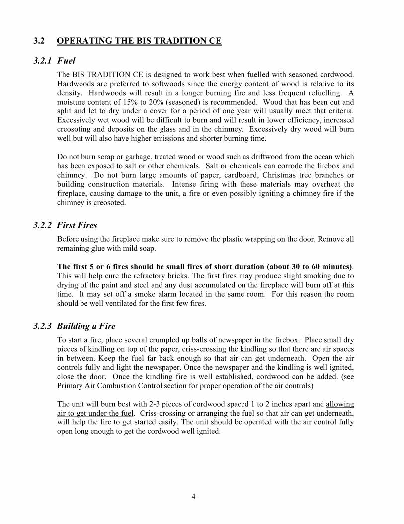
Year 1:Parts and labour (no charge)(see on page for exclusions and conditions)
Air control assemblyPlate, lever
Blower assemblyBlowers, wires, thermo disc
Ceramic glassGlass (thermal breakage)
Catalytic combustorCombustor (thermal degradation and disintegration),retainer
Air register assemblyPlate, lever
Door assemblyDoor, latch assembly, hinges, glass retainer, gaskets
Facade assemblyFacade, hardware
Fire box assemblyFire box, tube supports, tubes, deflectors
RefractoryRefractory (thermal breakage)
PaintDoors, louvers, fireplace facade
AccessoriesLog retainers, fire screen
Years 2 to 5:Parts (no charge)(see on page for exclusions and conditions)
Air control assemblyPlate, lever
Catalytic combustorCombustor (thermal degradation and disintegration),retainer
Air register assemblyPlate, lever
Door assemblyDoor, latch assembly, hinges, glass retainer, gaskets
Facade assemblyFacade, hardware
Fire box assemblyFire box, tube supports, tubes, deflectors
Years 6 to 25:Parts at 50% of published list price(see on page for exclusions and conditions)
Air control assemblyPlate, lever
Air register assemblyPlate, lever
Door assemblyDoor, latch assembly, hinges, glass retainer, gaskets
Facade assemblyFacade, hardware
Fire box assemblyFire box, tube supports, tubes, deflectors
Exclusions: Brass accessories installed on the fireplace: trims,louvers, surround kits.
Conditions:
1. The 25-year warranty begins from the date of purchase of thefireplace and is valid as long as this fireplace remainsinstalled in its original home. The fireplace must be installed,operated and maintained in accordance with the instructionsdescribed in the installation manual provided with it. Anyalteration, modification, accident, neglect or abuse of theproduct will void this guarantee.
2. A slight discoloration of painted parts, expansion, contractionor movement of certain parts, which cause light clickingnoises, is normal and is not a manufacturing defect.
3. Over firing of the fireplace (operation which causes metalparts to become red) can cause significant damage, create afire hazard and voids the warranty.
4. Security Chimneys International is not responsible for theinadequate performances of the fireplace caused by theenvironment such as trees, buildings, roofs, wind, hills,mountains near by, which may cause negative pressuresinside the home or mechanical causes such furnaces, blowersor cloth dryers.
5. This warranty does not cover normal wear and tear like thediscolouration or peeling of painted parts, worn or cutgaskets, chipped or cracked refractory.
6. Although your BIS fireplace is very efficient, it should not, inany case, replace the main heating system of the home inwhich it is installed. This fireplace is designed to supplementheat and comfort to the existing main heating system.

ii
TABLE OF CONTENTS
Page
1. SAFETY RULES ...................................................................................................... 1
2. CERTIFICATION LABEL ..................................................................................... 2
3. THE FIREPLACE .................................................................................................... 3
3.1 INTRODUCTION ......................................................................................................................... 33.1.1 Parts Required3.1.2 Additional Equipment (optional)
3.2 OPERATING THE BIS TRADITION CE ................................................................................. 43.2.1 Fuel3.2.2 First Fires3.2.3 Building a Fire3.2.4 Primary Air and Air Boost Controls3.2.5 Accelerated Combustion3.2.6 Medium Combustion3.2.7 Slow Combustion3.2.8 Refuelling For Best Performance3.2.9 Smoking – Causes And Troubleshooting
3.3 MAINTAINING YOUR BIS TRADITION CE .......................................................................... 83.3.1 Creosote3.3.2 Chimney Maintenance3.3.3 Top Baffle Removal Prior to Cleaning The Chimney3.3.4 Dealing With a Chimney Fire3.3.5 Finish Door Casing Care3.3.6 Ashes3.3.7 Refractory Installation3.3.8 Door Installation3.3.9 Door Adjustment3.3.10 Glass Care – Replacement3.3.11 Glass Care – Cleaning3.3.12 Gasket Replacement
3.4 FIREPLACE INSTALLATION .................................................................................................. 123.4.1 Locating The BIS TRADITION CE3.4.2 Hearth Extension Requirements3.4.3 Framing, Facing And Mantel
3.5 HOT AIR DUCTING INSTALLATION .................................................................................... 183.5.1 Gravity Kit3.5.2 Central Forced Air Kit
3.6 OUTSIDE AIR KIT ...................................................................................................................... 223.6.1 Outside Air Kit Installation
4. THE CHIMNEY ......................................................................................................... 234.1 CHIMNEY INSTALLATION NOTES ...................................................................................... 23
4.2 CHIMNEY INSTALLATION INSTRUCTIONS ...................................................................... 24
4.3 OFFSET CHIMNEY INSTALLATION .................................................................................... 27
4.4 ANGLED WALL RADIATION SHIELD .................................................................................. 30
4.5 CHIMNEY SUPPORTS INSTALLATION ............................................................................... 31
4.6 MULTIPLE TERMINATIONS .................................................................................................. 31
4.7 CHIMNEY ADAPTOR (S-2100+ / HT6000+) ........................................................................... 32
4.8 INSTALLATION INSTRUCTIONS FOR MASONRY APPLICATION ............................... 33
5. PARTS AND COMPONENTS LIST ..................................................................... 34
6. OPTIONS ................................................................................................................... 35
7. APPENDIX (Specifications, Clearances, Replacement Parts) ............................ 36

1
1. SAFETY RULES FOR OPERATING YOURFIREPLACE MODEL BIS TRADITION CE
• Use only a Security Fireplace glass door, specifically designed for the model BISTRADITION CE fireplace.
• When cleaning the fireplace, the ashes should be placed in a metal container with a tightfitting lid. The closed container of ashes should be placed on a non-combustible floor oron the ground outside the house, pending final disposal. If the ashes are disposed of byburial in soil or otherwise locally dispersed, they should be retained in the closedcontainer until all cinders have thoroughly cooled.
Warning: The fireplace must be operated with the door fully opened or fully closed. If the dooris left partly opened, smoke may be drawn into the room. If the unit is operated withthe door fully opened, the optional firescreen must be used.
Caution: Never use gasoline, kerosene, charcoal lighter fluid or similar liquids to startor rekindle a fire in this fireplace. Keep all such liquids well away from thefireplace at all times.
Caution: Keep combustible materials at least 48 inches away from the front of thefireplace opening.
Caution: Never leave children unattended when there is a fire burning in the fireplace.
WARNING: THIS FIREPLACE HAS NOT BEEN TESTED WITH AN UNVENTED ORVENTED GAS LOG SET. TO REDUCE RISK OF FIRE OR INJURY, DONOT INSTALL AN UNVENTED GAS LOG SET INTO THIS FIREPLACE.

2
2. CERTIFICATION LABEL

3
3. THE FIREPLACE
3.1 INTRODUCTION
The BIS TRADITION CE fireplace is an energy efficient, heat circulating, close combustionfireplace. You will receive a lifetime of comfort and enjoyment from your fireplaceprovided it is installed, maintained and operated properly.
• Please read these instructions and retain this manual for future reference.
• Before beginning the fireplace installation, consult the local authorities to obtain yourbuilding permit and check your local building codes. Install the fireplace only asdescribed in these instructions and using only Security Chimneys Internationalcomponents.
• The BIS TRADITION CE is not intended for use with a gas log. Failure to follow theseinstructions will void the certification and the warranty of the fireplace and may result inan unsafe installation.
3.1.1 Parts Required
• Fireplace model BIS TRADITION CE
• 6" diameter chimney model ASHT+, S-2100+, HT6000+, HT6103+ or ACmanufactured by Security Chimneys International only, including:
- Chimney lengths- Elbows (where necessary)- Associated components as per these installation instructions
3.1.2 Additional Equipment (optional)
• 5" flexible venting system (central forced air kit)• Gravity venting system• Rigid firescreen
4
3.2 OPERATING THE BIS TRADITION CE
3.2.1 Fuel
The BIS TRADITION CE is designed to work best when fuelled with seasoned cordwood.Hardwoods are preferred to softwoods since the energy content of wood is relative to itsdensity. Hardwoods will result in a longer burning fire and less frequent refuelling. Amoisture content of 15% to 20% (seasoned) is recommended. Wood that has been cut andsplit and let to dry under a cover for a period of one year will usually meet that criteria.Excessively wet wood will be difficult to burn and will result in lower efficiency, increasedcreosoting and deposits on the glass and in the chimney. Excessively dry wood will burnwell but will also have higher emissions and shorter burning time.
Do not burn scrap or garbage, treated wood or wood such as driftwood from the ocean whichhas been exposed to salt or other chemicals. Salt or chemicals can corrode the firebox andchimney. Do not burn large amounts of paper, cardboard, Christmas tree branches orbuilding construction materials. Intense firing with these materials may overheat thefireplace, causing damage to the unit, a fire or even possibly igniting a chimney fire if thechimney is creosoted.
3.2.2 First Fires
Before using the fireplace make sure to remove the plastic wrapping on the door. Remove allremaining glue with mild soap.
The first 5 or 6 fires should be small fires of short duration (about 30 to 60 minutes).This will help cure the refractory bricks. The first fires may produce slight smoking due todrying of the paint and steel and any dust accumulated on the fireplace will burn off at thistime. It may set off a smoke alarm located in the same room. For this reason the roomshould be well ventilated for the first few fires.
3.2.3 Building a Fire
To start a fire, place several crumpled up balls of newspaper in the firebox. Place small drypieces of kindling on top of the paper, criss-crossing the kindling so that there are air spacesin between. Keep the fuel far back enough so that air can get underneath. Open the aircontrols fully and light the newspaper. Once the newspaper and the kindling is well ignited,close the door. Once the kindling fire is well established, cordwood can be added. (seePrimary Air Combustion Control section for proper operation of the air controls)
The unit will burn best with 2-3 pieces of cordwood spaced 1 to 2 inches apart and allowingair to get under the fuel. Criss-crossing or arranging the fuel so that air can get underneath,will help the fire to get started easily. The unit should be operated with the air control fullyopen long enough to get the cordwood well ignited.

5
3.2.4 Primary Air and Air Boost Controls
There is no flue damper in the BIS TRADITION CE. As is common with air tight stoves,the combustion air control sets the flow of air entering the firebox. This allows for a moreprecise control of the fire. The combustion air control is located below the door on the leftside. The main source of air (primary air) entering the firebox can be diminished by movingthe air combustion control from left to right. The primary air is fully opened when the aircontrol is completely moved to the left. The air control device can also be used to add anextra boost of air especially during fire start up and reloading of the unit. Pulling the aircombustion control will induce an air boost at the base of the fire allowing an easier fire startup. When the fire is well established, the control can be pushed forward to shut down the airboost allowing for a longer burn time. The combustion air control should be in the closedposition (primary air and air boost) when the fireplace is not in use. This will minimize airleakage up the chimney. The combustion air control should be opened before opening thedoor to minimize the possibility of back draft coming into the room.
Figure 1
3.2.5 Accelerated Combustion
The maximum heat output for the BIS TRADITION CE is achieved by burning with the doorclosed and the combustion air opened and pulled back. By this method, the BISTRADITION CE can produce up to 55,000 BTU of heat per hour. However, it will benecessary to reload with wood every one or two hours. This is the least efficient method ofburning the BIS TRADITION CE.
Use caution when firing with the combustion air control wide open. Only burn cordwood inthis manner. Small dry pieces of softwood and construction scraps will burn very intenselyusing this method and may damage the firebox.

6
3.2.6 Medium Combustion
This is the recommended mode of operating the BIS TRADITION CE and should be the onenormally used since it will deposit the least amount of creosote on the glass and in thechimney. The combustion air control must be 3/4 closed and pushed forward to close the airboost. The precise setting will depend on many factors, including chimney length and themoisture content of the wood.
For instance, a long chimney will necessitate closing the damper more. To obtain the propercombustion, close the damper completely, then open it about 1/4" to 1/2". Three mediumsize pieces of wood should be burning on a bed of hot coals. The heat output will beapproximately 30,000 BTU per hour and the loading time will be about every 3-4 hours.Softwoods may be burned using this method but the time will be substantially reduced.
3.2.7 Slow Combustion
When the air combustion control is completely closed, the fireplace is in a slow combustionphase. If the hearth is hot enough, slow combustion will not stop the fire, but there will be anoticeable change in the flame pattern. The flames will be slow and may appear dirty if thewood is too wet (moisture content of 20% and more). Do not allow the wood to burn withoutflame, since this will produce excessive creosote in the unit.
Creosote may accumulate on the glass door. This method of burning should be used onlyafter operating the BIS TRADITION CE with the air control opened to produce a hot fire forabout an hour or at medium pace for at least 3 hres. Slow combustion can be used at night inorder to reduce the heat output and to prolong the burn. The loading time will be between 6-8hours.
3.2.8 Refuelling For Best Performance
The BIS fireplace will operate best if attention is given to operating the unit with the damperfully opened after refuelling in order to bring the firebox and the chimney system up to theiroptimum operating temperature. Combustion efficiency is relative to firebox temperature. Atemperature of 500º C and up, with a visible flame, in the upper part of the firebox indicatesa maximum efficiency. To obtain this temperature, the fireplace must be operated with theprimary air and air boost controls fully opened during 10 to 20 minutes after reloading,depending on the heat and on the moisture content of the wood. Once you have reached thedesired temperature, the air boost can be closed and the primary air set to a medium setting.You know you have reached the desired temperature when, closing the primary air control,you can see a flame at the top of the firebox. The benefit of this technique will be cleanerglass, less creosoting, greater efficiency and the most pleasing fire for your enjoyment. Ifyour fireplace is equipped with a central forced air system, make sure the central blower isturned off during reloading to avoid smoking problems.

7
3.2.9 Smoking – Causes and TroubleshootingTo reduce the likelihood of smoking when opening the door, set the combustion air controlsto the left before opening the door. Your fireplace has been designed and tested to providesmoke free operation. Occasionally, there may be a small amount of smoking upon lightingthe fire, until the chimney heats up but this should not continue. If the fireplace continues tosmoke it is probably for one of the following reasons:
A. Negative pressure in the houseAs the fire burns, air goes up the chimney. This air must be replaced through leakageinto the house or through the outside air duct. When operating the BIS TRADITION CE,open a nearby window temporarily to check if there is adequate air supply replacement.
B. Fans operating (e.g.: range hood)These fans draw air out of the house and may actually cause a negative pressure in thehouse. Turn off all fans and open a nearby window to determine if this is the cause of theproblem.
C. Wet woodWet or tarred wood will smoulder and smoke instead of burn properly.
D. Dirty or blocked chimneyCheck to make sure the chimney is clear and clean.
E. Chimney not long enoughThe minimum chimney height is 12 ft. not including the fireplace height. The chimneymust extend at least 3 feet (915 mm) above its point of contact with the roof and at least 2feet (610 mm) higher than any roof or wall within 10 feet (3 m) of it. When installedwith offsets, the minimum chimney height is 15 ft. Additional height will increasedraught and will decrease the tendency to smoke.
F. Poor chimney draft
With no fire, there should be sufficient draught to exhaust cigarette smoke introducedunder the baffle. Chimneys installed against an outside wall without protection maygenerate back draught problems which will cause start-up problems. To prevent this,open a nearby window, roll up a piece of paper and light it. Then, hold it in the upperpart of the firebox to warm up the chimney. Wait until the draught is sufficient, then startthe fire.
G. Blower for central forced air kit operating
Make sure that the blower is at the "off" position when you open the fireplace door forreloading.

8
IMPORTANT NOTES
A. Do not block the hot air vents to the fireplace as this will cause the fireplace to overheat.B. Never start a fire using gasoline, kerosene, charcoal lighter fluid or any other combustible
liquid.C. Do not burn coal. The sulphur in coal will corrode the firebox.D. Do not burn driftwood which has been in the ocean or salt water. The salt will corrode
the firebox and chimney.E. Do not burn wood in the area in front of the grate.F. Do not abuse the unit by burning paper, or cardboard or construction material such as
pressed wood, plywood or lumber.G. Do not allow the wood to smoulder or burn without flame, since this will produce
excessive creosote in the unit.
3.3 MAINTAINING YOUR BIS TRADITION CE
3.3.1 Creosote
When wood is burned slowly without a flame, it produces tar and other organic vapors whichcombine with expelled moisture to form a black deposit called creosote which accumulateson the flue lining. When ignited, this creosote makes an extremely hot fire. If the creosoteaccumulation is large, a creosote fire in the chimney can damage the chimney and overheatthe surrounding wood framing. Creosote formation in a chimney can be minimized bymaking sure there is always visible flame burning , avoid smouldering fires and by properrefuelling techniques.
3.3.2 Chimney Maintenance
Regular chimney inspection and maintenance combined with proper operation will preventchimney fires. Keep your chimney clean. Do not allow more than 1/16" creosote build up inyour chimney. The amount of creosote will depend on variables such as frequency of useand type of fire. We recommend that you:
A. Initially inspect the chimney system weekly. From this, you will learn how often it willbe necessary to clean your chimney.
B. Have your chimney cleaned by a qualified chimney sweep. If you wish to clean ityourself, we recommend using a stiff plastic or non-metallic brush. If a metal brush isused, its size should be slightly smaller than the flue to avoid damaging the chimney. Donot use a brush that will scratch the stainless steel interior of the chimney.
C. Do not expect chemical cleaners to keep your chimney clean. The rain cap can beremoved for inspection and/or cleaning of the chimney.

9
3.3.3 Top Baffle Removal Prior to Cleaning The Chimney
Before starting to clean your chimney, we recommend that you remove the top baffle toavoid creosote dust collection at the top of the baffle. Follow these steps to set the top baffleout of the way:
1. Remove the side refractory holder. They are located at the top of the refractory.
2. Lift the front baffle.
3. Slide the back baffle under the front baffle. You now have access to the chimney.
3.3.4 Dealing With a Chimney Fire
Regular chimney maintenance and inspection can prevent chimney fires. If you have achimney fire, follow these steps:
1. Close the fireplace door and the combustion air controls.
2. Alert your family of the possible danger.
3. If you require assistance, alert your fire department.
4. If possible, use a dry chemical fire extinguisher, baking soda or sand to control the fire.Do not use water as it may cause a dangerous steam explosion.
5. Check outside to ensure that sparks and hot embers coming out of the chimney are notigniting the roof.
6. Do not use the fireplace again until your chimney and fireplace have been inspected by aqualified chimney sweep or a Fire Department Inspector.
3.3.5 Finish Door Casing Care
Use a glass cleaner and a soft cloth to polish the casing. Do not use abrasives such as steelwool, steel pads or an abrasive polish for they may scratch the casing’s finish.
3.3.6 AshesRemove ashes only when the fire is out and the ashes are cold (24 to 48 hours after the fire isout).

10
3.3.7 Refractory Replacement
The intense heat of the fire will normally cause hairline cracks in the refractory. Thesecracks can be minimized by proper curing as described in "First fires". They will notnormally diminish the effectiveness of the refractory. If large cracks develop, then therefractory should be replaced. To replace the refractory bricks, follow these steps:
1. Remove the front refractories2. Remove the bottom refractory3. Remove the left side refractory4. Remove the right side refractory5. Remove the back refractory6. Remove the front ceramic baffle7. Remove the rear ceramic baffle
To install the new refractories, followthe above steps in reverse.
Figure 2
3.3.8 Door Installation
The door must be installed only whenthe installation of the BISTRADITION CE is completed. Allyou have to do is fit the male part ofthe hinge, already on the door, to thefemale part, which is on the fireplace.
To remove the door, simply pull thedoor up from the hinges.
The door adjustment has been set atthe factory. If the fit is still notperfect, you can adjust the door usingthe hinge screws.
Figure 3
11
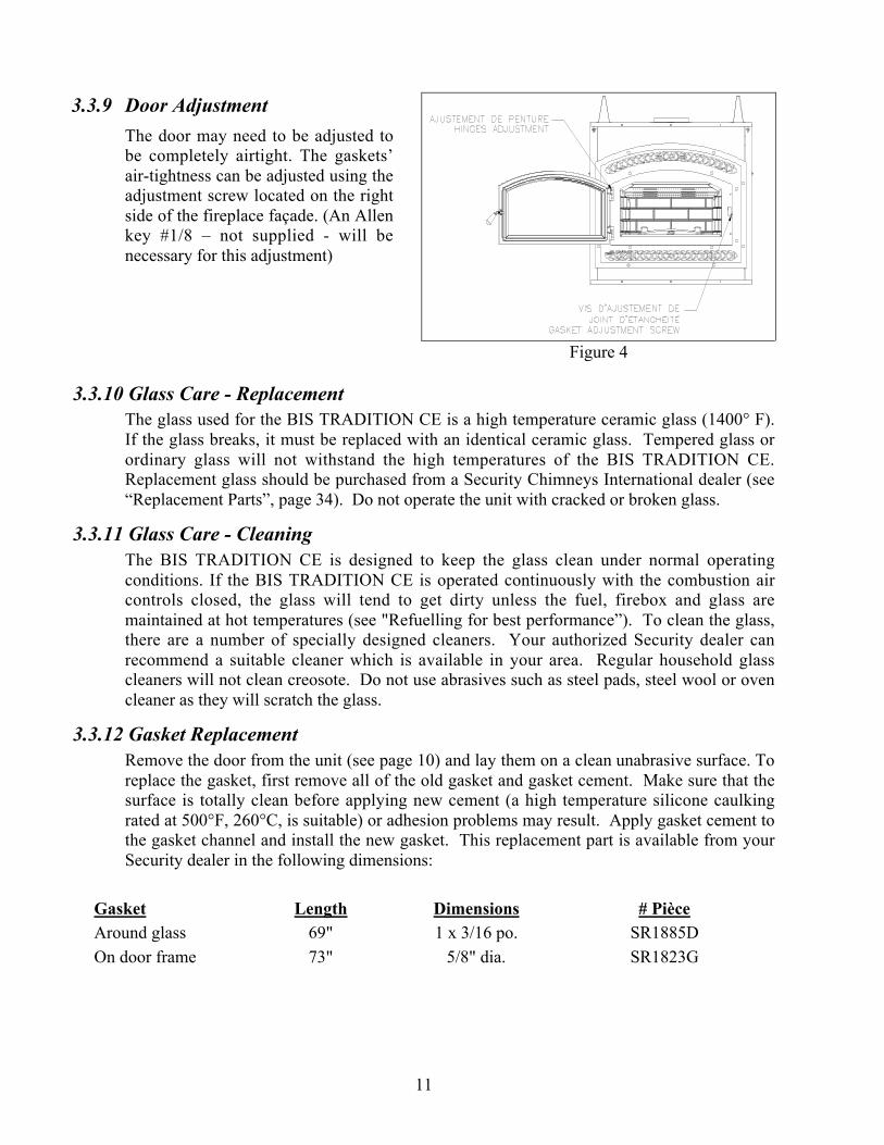
3.3.9 Door Adjustment
The door may need to be adjusted tobe completely airtight. The gaskets’air-tightness can be adjusted using theadjustment screw located on the rightside of the fireplace façade. (An Allenkey #1/8 – not supplied - will benecessary for this adjustment)
Figure 4
3.3.10 Glass Care - ReplacementThe glass used for the BIS TRADITION CE is a high temperature ceramic glass (1400° F).If the glass breaks, it must be replaced with an identical ceramic glass. Tempered glass orordinary glass will not withstand the high temperatures of the BIS TRADITION CE.Replacement glass should be purchased from a Security Chimneys International dealer (see“Replacement Parts”, page 34). Do not operate the unit with cracked or broken glass.
3.3.11 Glass Care - CleaningThe BIS TRADITION CE is designed to keep the glass clean under normal operatingconditions. If the BIS TRADITION CE is operated continuously with the combustion aircontrols closed, the glass will tend to get dirty unless the fuel, firebox and glass aremaintained at hot temperatures (see "Refuelling for best performance”). To clean the glass,there are a number of specially designed cleaners. Your authorized Security dealer canrecommend a suitable cleaner which is available in your area. Regular household glasscleaners will not clean creosote. Do not use abrasives such as steel pads, steel wool or ovencleaner as they will scratch the glass.
3.3.12 Gasket ReplacementRemove the door from the unit (see page 10) and lay them on a clean unabrasive surface. Toreplace the gasket, first remove all of the old gasket and gasket cement. Make sure that thesurface is totally clean before applying new cement (a high temperature silicone caulkingrated at 500°F, 260°C, is suitable) or adhesion problems may result. Apply gasket cement tothe gasket channel and install the new gasket. This replacement part is available from yourSecurity dealer in the following dimensions:
Gasket Length Dimensions # PièceAround glass 69" 1 x 3/16 po. SR1885DOn door frame 73" 5/8" dia. SR1823G

12
3.4 FIREPLACE INSTALLATION
3.4.1 Locating The BIS TRADITION CE
A. The best location to install your fireplace is determined by considering the location ofwindows, doors, and the traffic flow in the room where the fireplace is located, allowingspace in front of the unit for the hearth extension and the mantel, and taking intoconsideration the location of the hot air ducts (optional), outside air kit and chimney. Ifpossible, you should choose a location where the chimney will pass through the housewithout cutting floor or roof joists (see fireplace dimensions page 13).
B. Usually, no additional floor support is needed for the fireplace. The adequacy of thefloor can be checked by first estimating the weight of the fireplace system. Weights aregiven in the appendix. Next, measure the area occupied by the fireplace which isnormally 36" X 24 _". Note the floor construction and consult your local building codeto determine if additional support is needed.
C. The BIS TRADITION CE may be installed directly on the floor or on a raised base (forproper guidelines, refer to "Hearth Extension Requirements") and a minimum of 6'8"measured from the base of the appliance to the ceiling is required.
D. When selecting the location, the chimney outlet position and the direction of the wind areimportant factor affecting the chimney performance. To allow a maximum draft and toreduce wind turbulence, the chimney must:
• Penetrate the highest part of the roof.• Be installed as far as possible of roof offsets, trees or any other obstructions that may cause
wind turbulence and back drafts in the chimney.• The least amount of offsets (elbows) possible.

13
3.4.2 Hearth Extension Requirements
The BIS TRADITION CE may be installed directly on a combustible floor; however, thecombustible floor in front of the fireplace must be covered with a non-combustible material(tile, marble, stone, etc.).
Figure 5
14
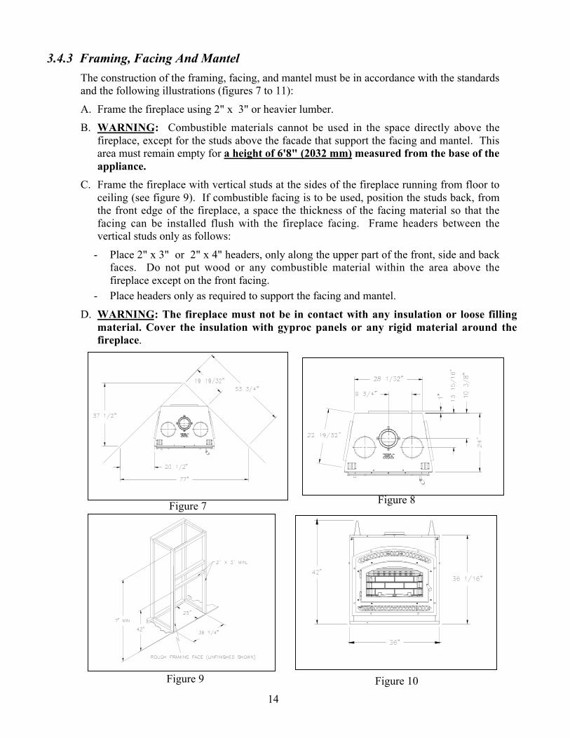
3.4.3 Framing, Facing And Mantel
The construction of the framing, facing, and mantel must be in accordance with the standardsand the following illustrations (figures 7 to 11):
A. Frame the fireplace using 2" x 3" or heavier lumber.
B. WARNING: Combustible materials cannot be used in the space directly above thefireplace, except for the studs above the facade that support the facing and mantel. Thisarea must remain empty for a height of 6'8" (2032 mm) measured from the base of theappliance.
C. Frame the fireplace with vertical studs at the sides of the fireplace running from floor toceiling (see figure 9). If combustible facing is to be used, position the studs back, fromthe front edge of the fireplace, a space the thickness of the facing material so that thefacing can be installed flush with the fireplace facing. Frame headers between thevertical studs only as follows:
- Place 2" x 3" or 2" x 4" headers, only along the upper part of the front, side and backfaces. Do not put wood or any combustible material within the area above thefireplace except on the front facing.
- Place headers only as required to support the facing and mantel.
D. WARNING: The fireplace must not be in contact with any insulation or loose fillingmaterial. Cover the insulation with gyproc panels or any rigid material around thefireplace.
Figure 7 Figure 8
Figure 9 Figure 10

15
INSULATED CHASE CONSTRUCTION
Figure 11

16
Facing
Note: The facade must be removable once installed. The facade isdesigned to overlap any facing material installed on the front ofthe fireplace. If thicker material is installed, use the facade as atemplate and make sure it can be easily removed for servicing.
1. Combustible material must be installed flush with the fireplace. It may not project infront of and on the fireplace (i.e. the steel facade of the fireplace) (figure 13b).
2. Non-combustible materials such as brick, stone or ceramic tile may project in front ofand onto the fireplace facing (figure 13c).
1. Fireplace2. Front of fireplace3. Wood frame (2” x 3” min)4. Drywall5. Tiles6. Rock board or other7. Brick
Mantel
The mantel must be installed at least 42" (1067 mm) above the base of the fireplace (figure12).
Figure 13a

17
Figure 13b Figure 13c
3.4.4 Fireplace Blower
The fireplace comes equipped with a heat activated blower. It is located in the bottom of thefireplace, towards the back. It uses regular 120V and must be connected to the mainelectrical circuit by a qualified electrician. For connection, use the electrical box suppliedwith the unit located on the bottom right corner of the fireplace.
If you wish to adjust the blower speed, an optional variable speed control (VRUW) can beinstalled in line with the wiring. Again, use a qualified electrician for installation.
If the blower requires servicing,
1- Remove the doors and the decorative facade
2- Remove the screw located below the blower motor that holds it to the back of thefireplace
3- Pull the blower out of the unit through the square hole located in the front bottomright corner.

18
3.5 HOT AIR DUCTING INSTALLATION
Different hot air ducting systems can be installed with the BIS TRADITION CE :- Gravity kit- Forced air kit
3.5.1 Gravity Kit
Two kits are available:
1. Single hot air outlet including: (see Fig.14)- 2 6" lengths 8" I.D.- 1 hot air outlet kit (box, louver and frame)- 2 adaptors
2. Double hot air outlet including: (See Fig.15)- 2 telescopic lengths 8" I.D.- 2 90º elbows 8" I.D.- 2 hot air outlet kits (grill and frames)- 2 adaptors
NOTE : If the fireplace is vented using the AC chimney and the single hot air outlet isinstalled, the chimney must be offset towards the back using 2 – 30 deg. elbows back to back onthe fireplace.
NOTE: For the double hot air outlet it is mandatory to install both outlet pipes. Any otherinstallation can cause fire and void warranty.
See components list page 33.
The only fan that can be used with the gravity kit is the is the one sold with the fireplace.
Figure 14 Figure 15
The safety rules for hot air ducting gravity kit installations are the following:
Minimum height* 68" (1727 mm)
Maximum length See figures 16 & 17The height of the louver must be measured from the base of the BIS to the middle point ofthe louver.

19
The single outlet system is designed to be installed either flush with the front of the BISTRADITION CE or extended out slightly from the face of the fireplace (if installing with abrick or thick facing for example). To extend the double outlet system, it will be necessaryto purchase two adjustable lengths (7B26ZL2A). To extend the single outlet, it is necessaryto install the insulation strip provided with the system. A maximum of 3 _" (89 mm) ofextension is provided by the single outlet system (see figure 17).
When installing the double outlet system, the hot air outlets can be installed in the sameroom as the fireplace, or one or both of the outlets can be installed in adjacent or upperrooms. Installing the ducts at different elevations will tend to exhaust more heat out of thehigher outlet (figure 16).
Figure 16 Figure 17
Figure 18

20
The duct system must be installed respecting the following:
1. Remove the top and bottom plates closing up the 8" dia. holes on top of the fireplace.Then, cut the insulation in order to obtain two 8" dia. free openings. Fix the adaptors onthe fireplace openings by turning clockwise (figures 14 and 15).
2. Maintain at least a 2" (50 mm) clearance between the ducts and any combustiblematerial; the required hole size is 13" x 13" (330 mm x 330 mm).
Exception #1: For the grills, the framing can be 10 _" x 10 _" (275 mm x 275 mm) toprovide the clearance as required by the integral spacers on the double outlet duct system.
Exception #2: For the single outlet, the framing must be 8 _" x 32 _" (210 mm x 820mm) or as required by the integrated spacers. At no time should any combustible facingmaterial such as panelling cover over any part of the grill face.
3. The maximum number of elbows in a run of duct is two.
4. Maintain at least 6 _" (160 mm) clearance from the outlet grill framing to a combustibleceiling, side wall or mantel.
5. When traversing a combustible wall or floor, a firestop must be installed at the wall orfloor penetration. The hole size must be 13" X 13". (330 mm x 330 mm)
6. Do not connect the hot air ducts to a central heating system. Malfunction of the heatingsystem’s fan will cause the fireplace to overheat. A furnace duct is only single wall andnot double wall as is required for the BIS TRADITION CE hot air exhaust.
7. Use only Security Chimneys International grills and components as described in thismanual. Other grills or registers, for example, may be too restrictive and may overheatthe fireplace or ceiling.
8. Do not use insulated flexible ducts as they will overheat.
9. Do not use tees or any other components than the ones specifically listed here.
10. All ducts must extend upwards or horizontally. Never route the ducting downwards.
11. The hot air outlet grills must be installed with the louvers pointing downwards in order toprevent overheating adjacent ceilings.

21
3.5.2 Central Forced Air Kit (Not tested under EPA certification)The knock-outs provided on the back and on the sides of the BIS TRADITION CE allow theconnection of insulated flexible pipe which enables you to heat adjacent rooms up to 50 feetfrom the fireplace.The ducting system must be installed as described below :A) Fix the adaptor at the back and/or the side of the fireplace by twist-locking the adaptor to
the fireplace. You can use more than one outlet on the fireplace (figure 19).B) Attach the 5" flexible pipe, using the collars provided. Important: Make sure that the
plastic wrapping around the flexible pipe will not be in contact with the fireplace.C) Route the flexible pipe to the chosen location. The ducting system can be installed either
in an upper room or in a lower room.D) Attach the flexible pipe to the fan, using the collars (figure 20).E) Fix the backdraft damper to the fan outlet.F) Attach a flexible pipe to the fan / flexible pipe adapter (square to round) and stretch it up
to the location where the heat is required.G) At that point, the flexible pipe can be attached to any air distribution grill. It is possible to
connect a flexible pipe to a central heating system. Make sure the pipe will be connectedto the warm air supply duct, not to the return air duct (figure 21).
H) Install the blower heating and cooling thermostat (HCTW) in that part of the house to beheated by the hot air duct. The thermostat can be switched to a cooling thermostat andinstalled in the same room as the unit. This thermostat will turn on the blower when theroom where the fireplace is located becomes too hot.
This option requires electricity. Make sure that the connections to the fan have been madeaccording to the local codes and comply with their requirements (see instruction providedwith the thermostat).
Figure 19 Figure 20

22
3.6 OUTSIDE AIR
It is mandatory to install an outside air connection to the BIS Tradition CE. The followingcomponents are required and are included with the fireplace:
- Outside air kit- 4" adapter for fireplace connection
The outside air assembly must be installed according to the following requirements :
A) Duct length should be kept to a minimum. The maximum length of a 4" interior diameter (100mm) insulated flexible duct is 20 ft. (6.1 m). The duct can be extended to a maximum of 40 ft.(12 m) using a 6" interior diameter (150 mm) insulated flexible duct (See note below).
B) The air intake register must not be installed more than 10 ft. (3050 mm) above the base of thefireplace.
C) The fresh air must come from outside the house. The air intake must not draw air from the attic,basement or garage.
D) The air intake should be installed where it is not likely to be blocked by snow or exposed toextreme wind and away from automobile exhaust fumes, gas meters and other vents.
E) The duct and register may be installed above or below floor level.
Make a 4 _" (110 mm) hole in the outside wall of the house at the chosen location. Fromoutside, place the outside air register in the hole (open side down) and fasten the register tothe wall with screws as shown (see figure 24). Slip the pipe into the insulated sleeve. Placethe insulated pipe over the register tube and over the fireplace’s outside air connector (seefigure 25). At each end, carefully pull back the insulation and plastic cover exposing theflexible pipe. Using the aluminium tape provided, wrap the tape around the joint betweenthe flexible pipe and the air inlets. Carefully push the insulation and plastic cover back overthe pipe. Using aluminium tape, fasten the plastic cover in place.
NOTE: We recommend not to exceed 20 feet of 4” flexible pipe. If you require a longerlength we recommend that you use a 5” diameter flexible pipe for the complete run up to 30feet and a 6” diameter pipe for a run of up to 40 feet.
Figure 24 Figure 25

23
4. THE CHIMNEY
4.1 CHIMNEY INSTALLATION NOTES
1. If possible, install an interior chimney as it will provide better performance. In areas withcontinuous temperatures below -18° C (0° F), the use of an exterior chimney increases thelikelihood of operating problems such as low draught, high rate of creosoting, and poorstart-up characteristics. Exterior chimneys are also prone to down-drafting and flowreversal. Installations, which are located on lower floors in the house, such as in abasement, in combination with outside chimney, are especially prone to flow reversal.
2. The Security fireplace model BIS TRADITION CE is listed only with Security ChimneysInternational Ltd 6" diameter chimney systems.
3. A chimney venting a fireplace shall not vent any other appliance.4. The minimum chimney height is 12 ft. (3.7 m).In altitude, add 18”(450mm) to the
chimney for every 2000 feet(600mm) above sea level.5. All chimney installations must include at least one support. Reducing the amount of
chimney weight on the fireplace will help avoid the noise created when the fireplaceexpands. This can be achieved by having the chimney supported by the supports. Themaximum chimney length that can be supported by the fireplace is 9 ft. (2.75 m) forS-2100+/HT6000+, 12 ft. (3.7 m) for ASHT+ / HT6103+ and 26 ft. (8 m) for ACchimney.
6. The chimney must extend at least 3 ft. (915 mm) above its point of contact with the roofand at least 2 ft. (610 mm) higher than any wall, roof or building within 10 ft. (3m) of it(Figure 26).
7. If the chimney extends higher than 5 ft.(1500 mm) above its point of contact withthe roof, it must be secured using a roofbrace.
8. A rain cap must be installed on top of thechimney. Failure to install a rain cap maycause corrosion problems.
9. Cut and frame square holes in all floors,ceilings, and roof that the chimney will gothrough to provide a 2" (50 mm) clearancebetween the chimney and any combustiblematerials. Do not fill this 2" space withinsulation or any other combustiblematerial.
10. Portions of the chimney which mayextend through accessible spaces must beenclosed to avoid contact withcombustible materials or damage thechimney.
Figure 26

24
4.2 CHIMNEY INSTALLATION INSTRUCTIONS
1. Cut and frame the holes in the ceiling, floor and roof where the chimney will pass (see figure 27).Use a plumb bob to line up the center of the holes. The sizes are indicated in table 1 for the floorand ceiling holes and table 2 (page 24) for the roof holes.
CHIMNEYMODEL
SQUARE HOLE SIZEOPENING
ASHT+ / HT6103+ 12 3/8" (314 mm)
S-2100+ / HT6000+ 14 1/8" (359 mm)
AC 15 " (380 mm)
Table 1 Figure 27
2. From below, install a firestop in each ceiling/floor separation through which the chimney willpass. At the attic level, install an attic radiation shield from above (figures 28 & 29).
3. For ASHT+ / HT6103+ and S-2100+ / HT6000+ chimneys, place the first chimney length on thefireplace. To lock it in place, turn _ of a turn clockwise. With the AC chimney, you must use astarter section before installing the first chimney length (figure 30). Continue installing chimneylengths making sure to lock each length in place.
4. Every time the chimney passes through a ceiling or a wall, install the appropriate firestop. Whenyou reach the desired height, install the roof support. (Refer to instructions included with thesupport).
5. Then, put the roof flashing in place and seal the joint between the roof and the flashing withroofing pitch (see figures 31 & 32). For sloping roofs, place the flashing under the upper shinglesand on top of the lower shingles. Nail the flashing to the roof, using roofing nails.
6. Place the storm collar over the flashing, and tighten it with the bolt supplied. Finally, seal thejoint between the storm collar and the chimney, using silicone caulking.
7. Install the chimney cap.
Figure 28 Figure 29

25
AC CHIMNEY INSTALLATION(AIR COOLED GALVALUME CHIMNEY)
Figure 30
Note: Outside air kits must be installed forboth fireplace and AC chimney.

26
Figure 31 Figure 32
Table 2
ROOF DOWN SLOPE HOLE SIZE
SLOPE ASHT+ / HT6103+ S-2100+ / HT6000+ AC
Roof Pitch 6" 6" 6"
0 * 12 3/8" (314 mm) 14 1/8" (359 mm) 15" (380 mm)
2/12 12 9/16" (319 mm) 14 3/8" (365 mm) 15 3/8" (390 mm)
4/12 13" (330 mm) 14 7/8" (378 mm) 16 1/8" (410 mm)
6/12 13 7/8" (352 mm) 15 _" (400 mm) 16 7/8" (430 mm)
8/12 14 7/8" (378 mm) 17" (432 mm) 18 1/4" (465 mm)
10/12 16 1/8" (410 mm) 18 3/8" (467 mm) 19 5/8" (500 mm)
12/12 17 1/2" (445 mm) 20" (508 mm) 21 3/8" (545 mm)
* CROSS SLOPE HOLE SIZE
AC CHIMNEY
27
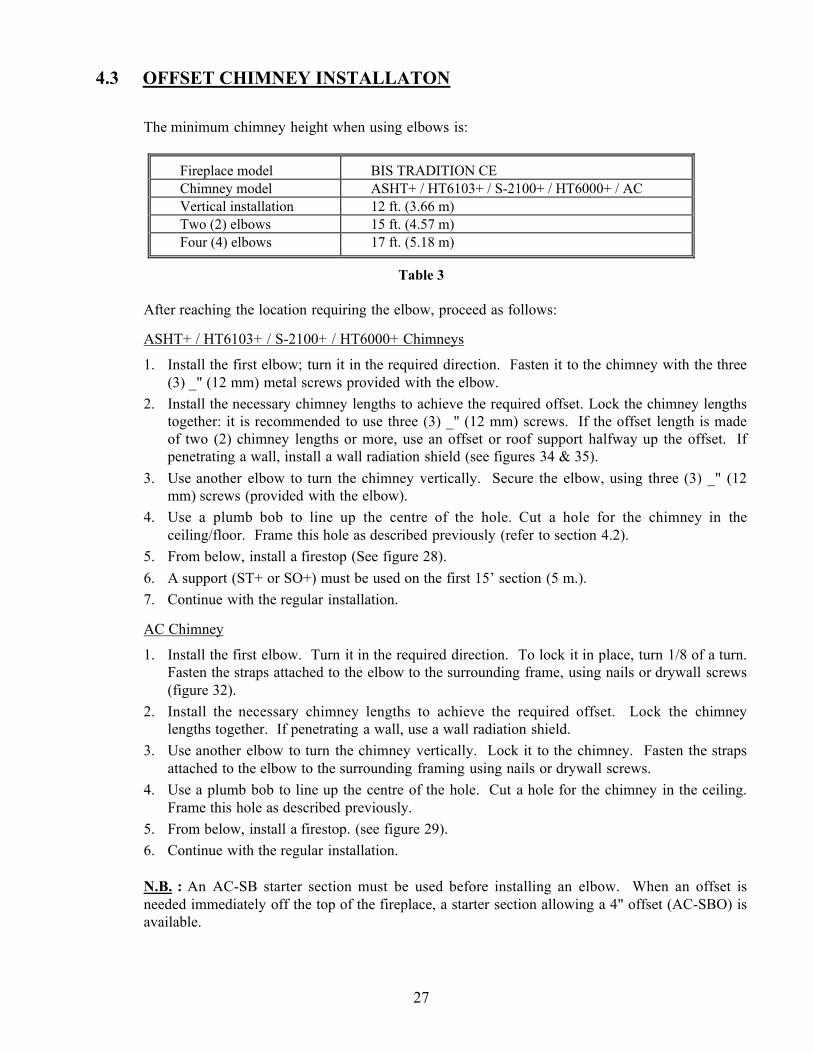
4.3 OFFSET CHIMNEY INSTALLATON
The minimum chimney height when using elbows is:
Fireplace model BIS TRADITION CEChimney model ASHT+ / HT6103+ / S-2100+ / HT6000+ / ACVertical installation 12 ft. (3.66 m)Two (2) elbows 15 ft. (4.57 m)Four (4) elbows 17 ft. (5.18 m)
Table 3
After reaching the location requiring the elbow, proceed as follows:
ASHT+ / HT6103+ / S-2100+ / HT6000+ Chimneys
1. Install the first elbow; turn it in the required direction. Fasten it to the chimney with the three(3) _" (12 mm) metal screws provided with the elbow.
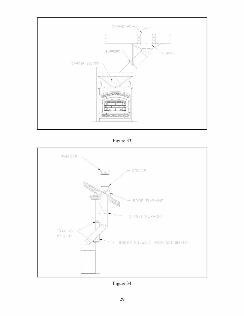
2. Install the necessary chimney lengths to achieve the required offset. Lock the chimney lengthstogether: it is recommended to use three (3) _" (12 mm) screws. If the offset length is madeof two (2) chimney lengths or more, use an offset or roof support halfway up the offset. Ifpenetrating a wall, install a wall radiation shield (see figures 34 & 35).
3. Use another elbow to turn the chimney vertically. Secure the elbow, using three (3) _" (12mm) screws (provided with the elbow).
4. Use a plumb bob to line up the centre of the hole. Cut a hole for the chimney in theceiling/floor. Frame this hole as described previously (refer to section 4.2).
5. From below, install a firestop (See figure 28).
6. A support (ST+ or SO+) must be used on the first 15’ section (5 m.).
7. Continue with the regular installation.
AC Chimney
1. Install the first elbow. Turn it in the required direction. To lock it in place, turn 1/8 of a turn.Fasten the straps attached to the elbow to the surrounding frame, using nails or drywall screws(figure 32).
2. Install the necessary chimney lengths to achieve the required offset. Lock the chimneylengths together. If penetrating a wall, use a wall radiation shield.
3. Use another elbow to turn the chimney vertically. Lock it to the chimney. Fasten the strapsattached to the elbow to the surrounding framing using nails or drywall screws.
4. Use a plumb bob to line up the centre of the hole. Cut a hole for the chimney in the ceiling.Frame this hole as described previously.
5. From below, install a firestop. (see figure 29).
6. Continue with the regular installation.
N.B. : An AC-SB starter section must be used before installing an elbow. When an offset isneeded immediately off the top of the fireplace, a starter section allowing a 4" offset (AC-SBO) isavailable.

28
Table 4
ONE LENGTH BETWEEN ELBOWS TWO LENGTHS BETWEEN ELBOWSCHIMNEY6” ELBOW
DEVIATION& HEIGHT 8” 12” 18” 24” 36” 48” 8” & 48” 12” & 48” 18” & 48” 24” & 48” 36” & 48” 48” & 48”
DEVIATION3 5/16"(84mm)
4 5/16"(110mm)
5 7/8"(149mm)
7 7/16"(189mm)
10 1/2"(267mm)
13 5/8"(346mm)
15 3/8"(391mm)
16 7/16"(418mm)
18"(457mm)
19 1/2"(495mm)
22 5/8"(575mm)
25 3/4"(654mm)
15º
HEIGHT15 11/16"(398mm)
19 9/16"(497mm)
25 3/8"(645mm)
31 3/16"(792mm)
42 3/4"(1086mm)
54 3/8"(1381mm)
60 15/16"(1548mm)
64 13/16"(1646mm)
70 9/16"(1792mm)
76 3/8"(1940mm)
87"(2210mm)
99 9/16"(2529mm)
DEVIATION7 7/16"
(189mm)9 7/16"
(240mm)12 7/16"(316mm)
15 7/16"(392mm)
21 7/16"(545mm)
27 7/16"(697mm)
30 13/16"(783mm)
32 13/16"(833mm)
35 13/16"(910mm)
38 13/16"(986mm)
44 13/16"(1138mm)
50 13/16"(1291mm)
30ºHEIGHT
20"(508mm)
23 _"(597mm)
28 11/16"(729mm)
33 7/8"(860mm)
44 1/4"(1124mm)
54 11/16"(1389mm)
60 9/16"(1538mm)
64 "(1627mm)
69 1/4"(1759mm)
74 7/16"(1891mm)
84 13/16"(2154mm)
95 1/4"(2419mm)
DEVIATION10 5/16"(262mm)
13 3/16"(335mm)
17 3/8"(441mm)
21 5/8"(549mm)
30 1/8"(765mm)
38 5/8"(981mm)
43 7/16"(113mm)
46 1/4"(1175mm)
50 1/2"(1283mm)
54 3/4"(1391mm)
63 1/4"(1607mm)
71 11/16"(1818mm)
SecureTempASHT+
NovaTempHT6103+
45ºHEIGHT
17 13/16"(452mm)
20 5/8"(524mm)
24 7/8"(632mm)
29 1/8"(740mm)
37 5/8"(956mm)
46 1/8"(1172mm)
50 15/16"(1294mm)
53 3/4"(1365mm)
58"(1473mm)
62 1/4"(1581mm)
70 3/4"(1797mm)
79 3/16"(2011mm)
ONE LENGTH BETWEEN ELBOWS TWO LENGTHS BETWEEN ELBOWSCHIMNEY6” ELBOW
DEVIATION& HEIGHT 8” 12” 18” 24” 36” 48” 8” & 48” 12 & 48” 18 & 48” 24” & 48” 36” & 48” 48” & 48”
DEVIATION3 5/16"(84mm)
4 5/16"(110mm)
5 7/8"(149mm)
7 7/16"(189mm)
10 1/2"(267mm)
13 5/8"(346mm)
15 1/2"(394mm)
16 1/2"(419mm)
18 1/16"(459mm)
19 5/8"(498mm)
22 3/4"(578mm)
25 13/16"(656mm)
15ºHEIGHT
16"(406mm)
19 7/8"(505mm)
25 11/16"(652mm)
31 1/2"(800mm)
43 1/16"(1094mm)
54 5/8"(1387mm)
61 7/16"(1561mm)
65 1/4"(1657mm)
71 1/16"(1805mm)
76 7/8"(1953mm)
88 1/2"(2248mm)
100 1/16"(2542mm)
DEVIATION7 3/8"
(187mm)9 3/8"
(238mm)12 3/8"
(314mm)15 3/8"
(391mm)21 3/8"
(543mm)27 3/8"
(695mm)30 7/8"
(784mm)32 7/8"
(835mm)35 7/8"
(911mm)38 7/8"
(987mm)44 7/8"
(1140mm)50 7/8"
(1292mm)
SecureTempS2100+
NovaTempHT6000+
30ºHEIGHT
20 11/16"(525mm)
24 3/16"(614mm)
29 3/8"(746mm)
34 9/16"(878mm)
44 15/16"(1141mm)
55 5/16"(1405mm)
61 3/8"(1559mm)
64 7/8"(1648mm)
70 1/16"(1780mm)
75 1/4"(1911mm)
35 5/8"(2175mm)
96"(2438mm)
ONE LENGTH BETWEEN ELBOWS TWO LENGTHS BETWEEN ELBOWSCHIMNEY6” ELBOW
DEVIATION& HEIGHT --- 12” 18” --- 36” 48” --- 12" & 48" 18" & 48" --- 36” & 48” 48” & 48”
DEVIATION ---4 13/16"(122mm)
6 1/8"(156mm)
11"(280mm)
14 1/8"(359mm)
16 7/8"(429mm)
18 7/16"(468mm)
23"(584mm)
26 3/16"(665mm)
15º
HEIGHT ---27 11/16"(703mm)
33 _"(851mm)
50 7/8"(1292mm)
65 _"(1588mm)
72 5/8"(1845mm)
78 7/16"(1992mm)
95 _"(2432mm)
107 3/8"(2727mm)
DEVIATION ---9 3/8"
(238mm)12 3/8"
(314mm)21 3/8"
(543mm)27 3/8"
(695mm)32 5/8"
(829mm)35 5/8"
(905mm)44 5/8"
(1134mm)50 5/8"
(1286mm)
AC 6"
30º
HEIGHT ---25 _"
(654mm)31"
(878mm)46 _"
(1181mm)57"
(1448mm)66"
(1676mm)71 _"
(1810mm)86 7/8"
(2207mm)97 _"
(2470mm)
*** NOTE : With the ACBI chimney, a starting length of 6” high must be used on top of the fireplace before installing ***
TOTAL HEIGHT
DEVIATION
29
Figure 33
Figure 34

30
4.4 ANGLED WALL RADIATION SHIELD(RSM+, RSMI30, RSMI45)
When traversing a combustible wall with the chimney at a 30º or 45º angle, an angledfirestop or wall radiation shield must be installed. Only one is required.
Note: 45º angle for Canada only
In cold climate locations, we recommend that you use the insulated wall radiation shieldsince it will maintain the home’s thermal barrier.
RSM+ and RSMI30, RSMI45
CHIMNEY MODEL ANGLE HOLE SIZE
ASHT+ / HT6103+ (6" dia.) 30º 283 mm x 781 mm (11 1/8" x 30 _")
Canada only 45º 283 mm x 518 mm (11 1/8" x 20 3/8")
S-2100+ / HT6000+ (6" dia.) 30º 327 mm x 881 mm (12 7/8" x 34 11/16")
AC (6" dia.) 30º 380 mm x 972 mm (15" x 38 _")
Table 5
Figure 35

31
4.5 CHIMNEY SUPPORT INSTALLATION
Universal Roof SupportThis support has three possible uses:
1. For ASHT+ / HT6103+ and S-2100+ / HT6000+, it must be used on a roof to supportthe chimney.
2. It may be used on a floor, ceiling or roof above an offset to support the chimneyabove the offset.
3. It may be used on a floor, ceiling or roof as a supplementary support
Table 6 gives maximum height of supported chimney.
NOTE: For the AC chimney, a support section must be used every 40 ft. (12 m) insteadof the universal roof support (ST).
For roof support installation, refer to the instructions provided with the support.
Universal Offset SupportThis support is used to support the chimney above an offset. When the chimney offset isused to traverse a wall this support may be used on the wall to support the chimney. Themaximum heights are given in Table 6. For offset support installation, refer to theinstructions provided with the support.
CHIMNEY MODEL MAXIMUM HEIGHT OF SUPPORTED CHIMNEY
OFFSET SUPPORT ROOF SUPPORT
ASHT+ / HT6103+ (6" dia.) 28 ft. (8.54m) 29 ft. (8.84 m)
S-2100+ / HT6000+ (6" dia.) 18 ft. (5.49 m) 20 ft. (6.1 m)
AC (6" dia.) 40 ft. (12.19 m) 50 ft. (15.20 m)
Table 6
4.6 CHIMNEY CHASE AND MULTIPLE TERMINATIONS
For the purpose of this manual, a chimney chase is considered a part of the chimneysystem rather than part of a building. The termination must be placed a minimum of 18"(460 mm) above the chase.
For installations where more than one chimney is located in the same chase or within thesame area, we suggest that their terminations be separated by at least 16" (410 mm)horizontally, and 18" (460 mm) vertically. This separation is to prevent smoke migratingfrom one chimney to another (see figure 36).

32
Figure 36
4.7 CHIMNEY ADAPTOR (S-2100+ / HT6000+)The fireplace is normally supplied with a chimney adaptor suitable for the ASHT+ /HT6103+ chimney. If you want to install a S-2100+ / HT6000+ chimney, an adaptor isavailable (6UCA) (figure 37). A separate starter section will also be required if ACchimney is installed.
Figure 37

33
4.8 INSTALLATION INSTRUCTIONS FOR MASONRY APPLICATION
WARNING: Before starting the installation, the masonry chimney must beinspected by a qualified sweep.
The following requirements must be respected:
1. The chimney must be absolutely clear of any soot residue or creosote. Check for cracks, loose or missingbricks that could inhibit correct installation of the liner.
2. The clearance to combustible must be a minimum of 1" between the outside of the masonry and any woodframing or loose insulation.
3. The chimney must be built in accordance with the current building code.4. No other appliance can be connected to the same chimney.5. The clearances to combustible for the BISUMA or BISPMA and BISUMA30 or BISPMA30 connectors are
2" on the side and bottom and 16" at the top.6. The connector parts are not necessary if the connection between the insulated length and the stainless
steel liner is done within the masonry chimney.
Installation:The chimney must be relined with a stainless steel liner model Tubinox or Projet SS of the same diameteras the outlet of the fireplace.For connection at 45º angle, a special connector (BISUMA for the BIS Ultra and BIS Tradition CEfireplaces or BISPMA for the BIS Panorama fireplace) must be used to connect the liner to the insulatedchimney. For connection at 30º, use the BISUMA30 or BISPMA30 connectors.
Follow these steps:
1- Position the fireplace in its location.Temporarily install the ASHT+ elbow onthe top of the fireplace and, using a level,mark with an oval the location where theflue liner will enter the masonry chimney.
2- In the middle of the oval, drill a hole in themasonry chimney at 45º or 30º.
3- Increase the size of the hole until a 45º or30º Tubinox liner elbow can be easilyslipped through.
4- Slide the liner down from the top of themasonry chimney until you reach the holelevel.
5- Slip through the hole a 45º or 30º linerelbow and connect it to the liner.
6- Add a small liner section to the liner elbowwhich will allow the liner to extend at least12” (measured at the top of the liner) fromthe masonry chimney.
7- Seal the opening around the liner with hightemperature refractory cement.
8- The next steps must be done in thefollowing order :
See typical installation illustrated below.
A. Select the ASHT + length that will fit between the elbow and the liner so that it will slide at least 2" over theliner section. (You may need to cut the liner for a better fit).
B. Take that section and the BISUMA or BISPMA (BISUMA30 or BISPMA30) cover and slide it over the liner.Make sure you have enough opening to be able to install the ASHT+ elbow without difficulty.
C. Install the 45º or 30º elbow on the fireplace.D. Slide the length section back down on the elbow and twist lock the two together.E. Pull the cover down over the length and install the insulation pad over the liner; be careful to cover the liner
completely.F. Slide back the cover over the insulation and fix it in place using the 3 metal screws supplied.
34
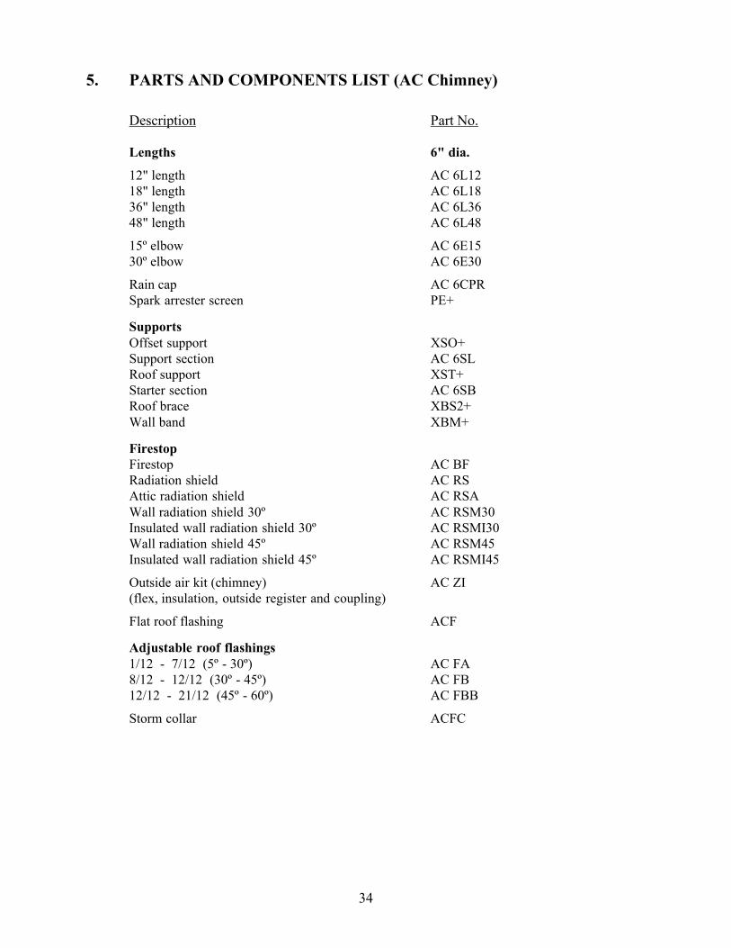
5. PARTS AND COMPONENTS LIST (AC Chimney)
Description Part No.
Lengths 6" dia.
12" length AC 6L1218" length AC 6L1836" length AC 6L3648" length AC 6L48
15º elbow AC 6E1530º elbow AC 6E30
Rain cap AC 6CPRSpark arrester screen PE+
SupportsOffset support XSO+Support section AC 6SLRoof support XST+Starter section AC 6SBRoof brace XBS2+Wall band XBM+
FirestopFirestop AC BFRadiation shield AC RSAttic radiation shield AC RSAWall radiation shield 30º AC RSM30Insulated wall radiation shield 30º AC RSMI30Wall radiation shield 45º AC RSM45Insulated wall radiation shield 45º AC RSMI45
Outside air kit (chimney) AC ZI(flex, insulation, outside register and coupling)
Flat roof flashing ACF
Adjustable roof flashings1/12 - 7/12 (5º - 30º) AC FA8/12 - 12/12 (30º - 45º) AC FB12/12 - 21/12 (45º - 60º) AC FBB
Storm collar ACFC

35
6. OPTIONS
Gravity kit: Part No.:
Complete double ducting system including: 2 elbows 90º,2 telescopic lengths, 2 grill supports and 2 black grills
7B30ZK-1
Complete single ducting system including: 2 x 6" lengths,1 decorative black frame and 1 black louver
7B26ZKS-1
Complete single ducting system including: 2 x 6" lengths,1 decorative brass frame and 1 brass louver
7B26ZKSB-1
Black grill with support 7B30ZO
Brass grill for 7B30ZK 7B30ZGB
1 brass louver & 1 decorative brass frame 7B26ZKSLB
Elbow 90º, 8" dia. 7B26ZE90
Elbow 45º, 8" dia. 7B26ZE45
Telescopic length, 8" dia. 7B26ZLA
Adjustable length 8" dia. (2" - 5") 7B26ZL2A
Radiation shield 7B26ZR
Central forced air kit:
Central forced air kit including: blower (BisZY), flexadaptor (BISAF), 2 clamps, variable speed control(VRUW), thermo-disk (VTU), fan to flexible pipeadapter(BISAVF), backdraft damper (BISBD),aluminium tape
BISFWK-1
Fireplace to Flex adaptor and 2 clamps BISAF
Flexible pipe 5" I.D. x 15 ft. Long 5FLEX15
Flexible pipe 5" I.D. x 30 ft. Long 5FLEX25
Blower 250 CFM for central forced air kit BISZY
Blower variable speed control with decorative wall plate for(BISZY)
VRUW
Thermo-disk, on/off blower control for (BISZY) VTU
Fan to Flexible pipe adaptor BISAVF
Heating and cooling thermostat HCTWFireplace:Rigid firescreen BUCEBWZN
Masonry chimney adaptor BISUMA

36
7. APPENDIX
SPECIFICATIONSWeight 300 lbsHeight 36"Width 36"Depth 24 1/2"Chimney weight ASHT+ (6" dia.) : 6.25 lb/ft.Chimney weight S-2100+ (6" dia.) : 10.8 lb/ft.
CLEARANCE TO COMBUSTIBLESThe following clearances meet the minimum requirements for a safe installationSide wall: 17" (324 mm) measured from the fireplace sideCeiling: 6’ 8" (2032 mm) measured from the base of the fireplaceFireplace enclosure: Bottom: 0” Side: 0”Back: 0”
Top: Do not fill the space above the fireplace with any material (Exceptthe wood framing. See page 14, Figure 8)
Chimney: 2" (50 mm)Mantel: 42" (1067 mm) measured from the base of the fireplace
REPLACEMENT PARTSBaffle refractory (2 pieces) PR-ISO2205Back refractory PR-SR2618Right side refractory PR-SR2619DLeft side refractory PR-SR2619GBottom refractory PR-SR2201Front refractory, right side PR-SR2202DFront refractory, left side PR-SR2202G
Secondary air tube PR-SR2271Secondary air tube lock PR-SR2214Cast-iron log supports (2) PR-SR2324Log retainer bar PR-SR2620Fireplace top PR-SR2591Fireplace left side PR-SR2575Fireplace right side PR-SR2576Fireplace back PR-SR2589
Touch up spray paint black SBMB6309Touch up spray paint charcoal PR-P6201(for hammered façade)
Door handle PR-SR1787Door rod and lock PR-SR2118Ceramic glass panel PR-SR2222-1Door gasket PR-SR1823GGlass gasket PR-SR1685DHinges (door & fireplace) PR-SR2395TCE