Contributions à la détection des comportements malhonnêtes ...
Upload
truongphucCategory
view
216download
0
MANUEL DE L’UTILISATEURUSER MANUAL

Jet P
ack
1
INDEX
DESCRIPTION 3
SECURITE – COMPORTEMENTS A RISQUES – INFORMATIONS GENERALES 3
PRATIQUE DU JET PACK BY ZR AVEC LE KIT DE GESTION ELECTRONIQUE 5
DEBUTER EN JET PACK BY ZR 6
TYPE DE VNM A UTILISER 7
ADAPTATION VNM 7
OU PRATIQUER LE JET PACK BY ZR ? 7
MAINTENANCE ET ENTRETIEN 8
GARANTIE 8
JET PACK BY ZR 9
PHASE 01 : MONTAGE DE L’INTERFACE TURBINE AVEC L’ADAPTATEUR ASSEMBLY OF THE PUMP INTERFACE WITH THE ADAPTER 10
PHASE 02 : MONTAGE DE L’INTERFACE TURBINE AVEC L’ADAPTATEUR ASSEMBLY OF THE PUMP INTERFACE WITH THE ADAPTER 11
FB03KAF01: ADAPTATEUR SEA DOO SEA DOO ADAPTER KIT 12
FB03KAF02: ADAPTATEUR SEA DOO 2010 SEA DOO 2010 ADAPTER KIT 13
FB03KAF03: ADAPTATEUR KAWASAKI 15F KAWASAKI 15F ADAPTER KIT 14
FB03KAF04: ADAPTATEUR KAWASAKI ULTRA KAWASAKI ULTRA ADAPTER KIT 15
FB03KAF05: ADAPTATEUR YAMAHA YAMAHA ADAPTER KIT 16
FB03KAF06: ADAPTATEUR HONDA HONDA ADAPTER KIT 17
PHASE 03 : MONTAGE DE LA CONNEXION VNM PWC CONNECTION ASSEMBLY 18
PHASE 03BIS : MONTAGE DE LA CONNEXION VNM SUR SEA DOO SPARK PWC CONNECTION ASSEMBLY WITH SEA DOO SPARK 19
PHASE 04 : MONTAGE DE L’ENSEMBLE SANGLES/MOUSQUETON ASSEMBLY OF THE STRAPS AND CARABINER 27
PHASE 05: MONTAGE DU PIVOT TUYAU HOSE SWIVEL ASSEMBLY 28
PHASE 06 : MONTAGE DES BRAS ARMS ASSEMBLY 29
PHASE 07 : MONTAGE DE SUPPORTS POIGNEES -HANDLE HOUSING ASSEMBLY 30
PHASE 08 : MONTAGE DES BAGUES DE BUSES- ASSEMBLY OF THE NOZZLES’ RINGS 31
PHASE 09: REGLAGE DE L’INCLINAISON DES BUSES- ADJUSTING THE POSITION OF THE NOZZLES 32
PHASE 10 : MONTAGE RAPIDE TUYAU / SIÈGE - QUICK CONNECTION HOSE / SEAT 34
PHASE 11 : RÉGLAGE DES SANGLES- ADJUSTING THE STRAPS 35
PHASE 12: INSTALLATION DE LA TELECOMMANDE EMK (OPTIONNEL) - WIRELESS REMOTE ASSEMBLY (OPTIONNAL) 37
Jet P
ack
PHASE 13 : INSTALLATION DU QUICK NOZZLE (OPTIONNEL) - QUICK NOZZLE INSTALLATION (OPTIONAL) 39
FB03QN1 : MODELE SEA DOO - SEA DOO MODEL 39
FB03QN2 : MODELE SEA DOO 2010 - SEA DOO 2010 MODEL 40
FB03QN3 : MODELE KAWASAKI 15F - KAWASAKI 15F MODEL 41
FB03QN4 : MODELE KAWASAKI ULTRA - KAWASAKI ULTRA MODEL 42
FB03QN5 : MODELE YAMAHA - YAMAHA MODEL 43
FB03QN6 : MODELE HONDA - HONDA MODEL 44
ANNEXE 1 : SIÈGE JET PACK BY ZR ANNEX 1 : JET PACK BY ZR SEAT 45
ANNEXE 2 : FB03A01- COUDE DE SORTIE ANNEX 2 : FB03A01 - U PIPE 47
ANNEXE 3 : FB05A01- COUDE DE SORTIE SEA DOO SPARK ANNEX 3 : FB05A01 – SEA DOO SPARK U PIPE 48
ANNEXE 4 : FB03A08: INTERFACE TURBINE ANNEX 4: FB03A08 – PUMP INTERFACE 49
ANNEXE 5 : FB03A03 - PIVOT TUYAU ANNEX 5 : FB03A03 - HOSE SWIVEL 50
ANNEXE 6 : JP01A07 - KIT ACCESSOIRES JET PACK BY ZR ANNEX 6 : JP01A07 - JET PACK BY ZR ACCESSORIES KIT 51
ANNEXE 7 : FB03QN – SOUS ENSEMBLE NOZZLE (OPTIONNEL) ANNEX 7 : FB03QN - NOZZLE (OPTIONAL) 52
ANNEXE 8 : COMMENT CHOISIR SON TUYAU JET PACK BY ZR ANNEX 8 : HOW TO CHOOSE YOUR JET PACK BY ZR HOSE 53
ANNEXE 9 : MODIFICATION DU PIVOT TUYAU FB03A03 EXISTANT - ANNEX 9 MODIFICATION OF HOSE SWIVEL 54
ANNEXE 10 : TRAITEMENT DU PROBLEME DE VIBRATIONS - SOLVING VIBRATION PROBLEMS 55
DESCRIPTION 56
SAFETY – RISKY BEHAVIOUR – GENERAL INFORMATION 56
USING THE JET PACK BY ZR FOR THE FIRST TIME 58
USING THE JET PACK BY ZR WITH EMK (OPTIONAL) 58
TYPE OF PWC 58
ADAPTATION TO THE PWC 59
WHERE TO PRACTICE JET PACK BY ZR? 59
MAINTENANCE – AFTER SALES SERVICE 59
WARRANTY 59
2

3
DESCRIPTION
Le Jet Pack by ZR est un engin qui permet de se propulser aussi bien dans les airs, à la surface ainsi que sous la surface de l’eau..
Les buses situées au niveau des épaules créent la poussée et servent à se déplacer en fonction de la position des bras de l'utilisateur du Jet Pack by ZR.
Malgré son utilisation très intuitive, le Jet Pack by ZR n’en reste pas moins un engin de sport extrême à pratiquer avec vigilance. Il a été conçu dans
l’optique d’être accessible au plus grand nombre, dans un but purement récréatif et non plus les figures et cascades.
95% des pièces du Jet Pack by ZR sont fabriquées en France.
SECURITE – COMPORTEMENTS A RISQUES – INFORMATIONS GENERALES
Il est recommandé d’avoir plus de 16 ans pour utiliser le Jet Pack by ZR (sans restriction de poids).
Il est interdit et dangereux de pratiquer le Jet Pack by ZR lors de vents supérieurs à 60 km/h et dans des vagues dépassant 1 mètre de hauteur.
Il est obligatoire de faire une heure de formation dans un centre d’initiation spécialisée avec un moniteur afin de comprendre le fonctionnement de
base et d’assimiler les notions principales de sécurité (se référer à la rubrique «SPOTS ZR» sur le site www.zapata-racing.com).
Il est formellement interdit d’utiliser le Jet Pack by ZR sous l’emprise d’alcool, de stupéfiants ou de médicaments diminuant la vigilance.
MATERIEL OBLIGATOIRE
- Gilet de flottabilité aux normes CE
- Casque type wakeboard
- Short néoprène (la pénétration de l’eau par les orifices du corps lors d’une chute ou lors du contact avec les jets d’eau du Jet
Pack by ZR risque de provoquer des blessures internes graves). Le port d’un simple maillot de bain ne constitue pas une pro-
tection adéquate contre la puissance de pénétration de l’eau dans les orifices inférieurs du corps.
TRES IMPORTANT
Il est indispensable de suivre les lois de navigation en vigueur dans le pays où le Jet Pack by ZR sera utilisé.
S’assurer que la zone où le Jet Pack by ZR sera utilisé soit dégagée de tout autre véhicule nautique tel que bateau, autre VNM ou autre utilisateur
de Jet Pack by ZR ainsi que de baigneurs, plongeurs et autres usagers de la mer.
Avant de s’élever à une hauteur supérieure à 2 mètres ou de plonger : s’assurer que la profondeur minimum soit de 4 mètres
et que l’eau soit assez claire pour estimer la profondeur ainsi que les reliefs les yeux ouverts dans l’eau.
Il est fortement déconseillé de décoller, atterrir ou utiliser le Jet Pack by ZR à proximité de toute source de risque telle que rochers, quais, plages,
bateaux, berges etc., le risque de se blesser en heurtant ces surfaces est très important.
Ne pas dépasser ses limites et éviter toute manœuvre agressive afin de réduire les risques de perte de contrôle.

4
Il s’agit d’un engin à haute performance et non d’un jouet.
Ne pas reproduire les figures et les comportements à risques vus à la télévision ou sur Internet (ex : back-flips), ceux-ci sont réalisés par des profes-sionnels, vous risqueriez de subir de sérieux dommages corporels et de mettre votre vie en danger ainsi que d’endommager sérieusement le matériel(Jet Pack by ZR, VNM) si les figures ne sont pas accomplies parfaitement.
Ne pas prendre de trajectoire trop serrée opposée au VNM mais accompagner le virage avec un rayon de courbure de 4 mètres minimum. Une tra-jectoire trop agressive entraîne un freinage brutal du Jet Pack by ZR ainsi qu’un virage brutal du VNM ayant pour conséquence éventuelle :- la chute de l’utilisateur du Jet Pack by ZR- la chute du conducteur du VNM- la casse du matériel telle que les pièces réf. FB02020 – FB02021 – FB02022 (sangles et mousqueton)- l’endommagement du tuyau (à l’exception du tuyau X-Armor réf. ZR01003 ou ZR01003-23) en provoquant un décollement entre la paroi interneet externe du tuyau au niveau de la liaison avec la sangle, voire le déchirement immédiat ou différé du tuyau.
Ne pas tourner à 360° devant le VNM au risque d’endommager le tuyau (à l’exception du tuyau X-Armor réf. ZR01003 ou ZR01003-23) en pro-voquant soit un décollement entre la paroi interne et externe du tuyau, soit un déchirement immédiat ou différé du tuyau.
Lorsque le Jet Pack by ZR est utilisé par 2 personnes (sans kit de gestion électronique (optionnel, voir page 5)), le conducteur du VNM ne doit jamaisdépasser les 6000 tours/min, il est préconisé d’utiliser la clé bridée pour des VNM de plus de 250 CV.

5
L’utilisateur du Jet Pack by ZR et le conducteur du VNM doivent s’assurer que l’utilisateur du Jet Pack by ZR ait une stabilité suffisante et qu’il ne
fasse plus de chute sur le dos avant de franchir une nouvelle étape de hauteur.
L’utilisateur du Jet Pack by ZR et le conducteur du VNM doivent s’assurer que la distance entre le VNM et Jet Pack by ZR n’est jamais inférieure
à 4 mètres.
L’utilisateur du Jet Pack by ZR doit absolument toujours être en position d’avancer et ne jamais reculer afin de limiter les chutes sur le dos.
L’utilisateur du Jet Pack by ZR doit en permanence contrôler la position du VNM par rapport à lui et être d’autant plus vigilant lorsqu’il s’élève à des
hauteurs supérieures à 4 mètres.
L’utilisateur du Jet Pack by ZR doit également contrôler en permanence la présence d’éventuels objets, récifs, bouées, etc… .
Lors de chutes dans l’eau, l’utilisateur du Jet Pack by ZR doit en permanence vérifier la distance entre lui et le VNM auquel il est connecté. En effet
l’inertie peut pousser le VNM jusqu’à lui à une vitesse faible mais susceptible de le surprendre ou de l’impressionner.
Lors de chutes dans l’eau, il est indispensable que l’utilisateur du Jet Pack by ZR ou le conducteur du VNM relâchent l’accélérateur le plus vite possible
et éteigne le moteur.
Lorsque l’utilisateur du Jet Pack by ZR est sous l’eau (chute ou plongeon) le conducteur du VNM doit immédiatement relâcher les gaz et couper le
moteur.
Un niveau minimum en natation est obligatoire, le Jet Pack by ZR ne doit pas être utilisé par des personnes phobiques de l’eau.
Lors de chutes, plus particulièrement sur le dos, l’utilisateur du Jet Pack by ZR peut descendre à une profondeur d’environ 2 mètres, il doit donc
anticiper une apnée d’environ 10 secondes au moment de la chute et pendant l’immersion. A tout moment l’utilisateur du Jet Pack by ZR doit se
tenir prêt à cette éventualité, il est conseillé de retomber le plus possible de face.
Ne jamais prendre une trajectoire en direction du VNM aussi bien de face que de dos.
Note : les roulements du Jet Pack by ZR nécessitent 10 minutes de rodage pendant lesquelles ils seront plus rigides que la normale.
PRATIQUE DU JET PACK BY ZR AVEC LE KIT DE GESTION ELECTRONIQUE
REF ZR01300 – OPTIONNEL
Si l’utilisateur du Jet Pack by ZR utilise le kit de gestion électronique ZAPATA RACING® (ZR01300) pour la première fois, il doit commencer en
utilisant le niveau 1 (1 seule LED éclairée) pendant minimum 20 minutes.
Chaque niveau doit être pratiqué pendant 20 minutes minimum avant de franchir le niveau supérieur.
A l’exception du niveau 4 qui ne doit jamais être utilisé avant 5 heures d’entraînement au niveau 3, et le niveau 5 qui ne doit jamais être utilisé
avant 10 heures d’entraînement au niveau 4.

6
DEBUTER EN JET PACK BY ZR
Il est obligatoire de faire une session de formation dans un centre d’initiation spécialisé avec un moniteur afin de comprendre le fonctionnement de
base et d’assimiler les notions principales de sécurité (se référer à la rubrique «SPOTS ZR» sur le site www.zapata-racing.com).
Pour faire décoller une personne débutante, le conducteur du VNM ne doit jamais dépasser 4500 tours/min, il ne faut surtout pas accélérer si l’uti-
lisateur ne parvient pas à sortir de l’eau car l’utilisateur risque d’être propulsé dans les airs lors du positionnement des pieds à plat.
Si la personne n’arrive pas à décoller, cela signifie que ses bras ne sont pas positionnés correctement.
Consultez cette vidéo de tutoriel en complément : https://www.youtube.com/watch?v=fMrzbMyoyrM&nohtml5=False
Position correcte pour décoller.
Position incorrecte pour décoller.

7
TYPE DE VNM A UTILISER
Tout type de VNM à condition qu’il soit homologué et certifié par les autorités du pays dans lequel il est utilisé.
Puissance requise :
Minimum : 90 CV
Maximum : 300 CV
Il est extrêmement dangereux et déconseillé de retirer les éléments de flottabilité du VNM.
ADAPTATION VNM
Pour adapter le Jet Pack by ZR sur le VNM :
a) Démonter le système de direction et le système de marche arrière
b) Monter l’interface turbine (réf. FB03A08, page 10) avec l’adaptateur approprié à la marque et au modèle du VNM.
Les adaptateurs, permettant l’installation du kit Jet Pack by ZR sur toutes les grandes marques de VNM (Sea Doo, Yamaha, Kawasaki et Honda),
sont disponibles au sein du réseau de distribution. Attention, l’adaptateur est indispensable pour installer le Jet Pack by ZR sur le VNM, aussi il faudra
préciser la marque du VNM utilisé à votre revendeur.
Adapter le Jet Pack by ZR sur le Sea Doo Spark :
Un système d’adaptation spécifique est disponible pour l’utilisation du Jet Pack by ZR avec le Sea Doo Spark (2 ou 3 places, avec ou sans IBR,
recommandé pour les 90CV). Se référer à la page 18 pour les instructions de montage complètes.
OU PRATIQUER LE JET PACK BY ZR ?
Le Jet Pack by ZR peut s’utiliser aussi bien en lac ou étang qu’en haute mer à condition que la profondeur minimum d’eau de 4 mètres soit respec-
tée.
Il est strictement interdit d’utiliser le Jet Pack by ZR dans des endroits exigus tels que bassins, piscines etc...
Ne pas démarrer le VNM ou utiliser le Jet Pack by ZR dans des profondeurs d’eau insuffisantes (inférieures à 1m) avec un fond sableux, au risque
d’endommager les roulements du kit le Jet Pack by ZR.
Dans l’éventualité de cette utilisation, vérifier le fonctionnement de tous les roulements avant la prochain utilisation afin d’éviter de lourdes casses
du matériel.
Attention, il en va de la responsabilité de l’utilisateur de s’assurer qu’il y ait une profondeur d’eau suffisante dans le lieu choisi.

8
MAINTENANCE ET ENTRETIEN
ATTENTION : Ne JAMAIS utiliser d’hydrocarbures type acétone ou essence sur les pièces en polycarbonate (transparentes) car
ces produits agressent et peuvent sérieusement endommager le matériel.
Afin d’assurer une bonne sécurité, il est recommandé de :
• Vérifier tout le serrage du siège du Jet Pack by ZR après 2h d’utilisation.
• Changer le tuyau tous les 2 ans.
• Changer les billes plastique réf. FB02267 (incluses dans le pivot réf. FB03A03 et les roulements du Jet Pack by ZR réf. FB04B01) tou
les ans. Pour le montage, utiliser de la graisse silicone ou vaseline (surtout pas de graisse marine, ou autre produit contenant des
hydrocarbures
qui pourraient agresser le matériau).
• Changer les bagues réf. FB04070, FB04071, FB04087, FB04094 et FB03011 tous les ans.
• Rincer le Jet Pack by ZR intégralement à l’eau claire après chaque utilisation (tuyau, siège) et le stocker dans un endroit sec à l’abri
du soleil (il n’est pas nécessaire de rincer le tuyau X-Armor réf. ZR01003 et ZR01003-23).
• Ne pas tirer le tuyau sur le sol lorsqu’il est plein d’eau (ceci ne s’applique pas au tuyau X-Armor réf. ZR01003 et ZR01003-23).
• Rincer, sécher et enrouler le tuyau après chaque utilisation et stocké à l’abri du soleil (ceci ne s’applique pas au tuyau X-Armor
réf. ZR01003 et ZR01003-23).
GARANTIE
Le Jet Pack by ZR est garanti contre tout défaut de fabrication pendant 1 an suivant la date d’achat. Une facture d’achat sera
demandée pour toute réclamation.
ZAPATA RACING® ne garantit le Jet Pack by ZR que dans le cadre d’une utilisation telle que décrite dans ce manuel.
La garantie est limitée au fonctionnement et non à l’état visuel des pièces.
La garantie ne couvre pas les pièces d’usure (exemple : billes réf. FB02267, tuyau (réf. FB02002 / ZR01002 / ZR01002-23), bagues réf. FB04070,
FB04071, FB04094 et FB03011 etc.).
Le Jet Pack by ZR doit être utilisé dans sa configuration d’origine. Il est formellement interdit et dangereux de modifier, supprimer ou ajouter des pièces à
l’exception de celles fournies par ZAPATA RACING®.
Les casses de matériel engendrées par les chutes violentes et/ou liées à une utilisation extrême ne sont pas couvertes par la garantie. En aucun cas la
responsabilité de ZAPATA RACING® ne pourra être mise en cause.
9
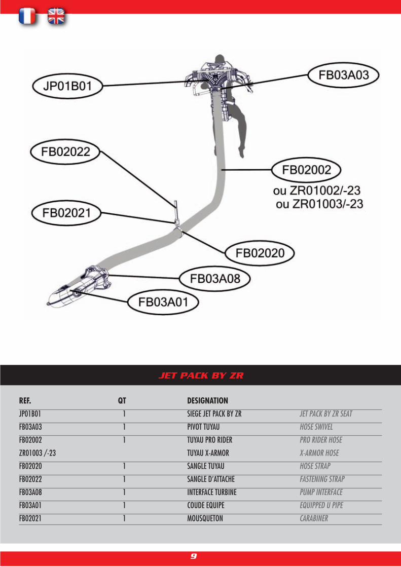
JET PACK BY ZR
REF. QT DESIGNATION
JP01B01 1 SIEGE JET PACK BY ZR JET PACK BY ZR SEAT
FB03A03 1 PIVOT TUYAU HOSE SWIVEL
FB02002 1 TUYAU PRO RIDER PRO RIDER HOSE
ZR01003 /-23 TUYAU X-ARMOR X-ARMOR HOSE
FB02020 1 SANGLE TUYAU HOSE STRAP
FB02022 1 SANGLE D’ATTACHE FASTENING STRAP
FB03A08 1 INTERFACE TURBINE PUMP INTERFACE
FB03A01 1 COUDE EQUIPE EQUIPPED U PIPE
FB02021 1 MOUSQUETON CARABINER

10
Positionner les pontets réf. JP01014 et JP01017 de manière à recouvrir le tube en aluminium (se référer à l'illustration pour le positionnement exact).
Bien respecter le sens : JP01014 du côté avant du connecteur et JP01017 du côté arrière.
Positionner le cylindre JP01013 côté avant, de manière à s’aligner avec le trou central des platines triangulaires.
Place and align the seat against bridges and the cylinder, in order to :
- insert the 4 screws ref. JP01018 through the bridges until they are screwed in the seat
- insert screw ref. JP01020 through the middle hole of the plates and through the cylinder ref. JP01013 until it is screwed in the seat
Use medium thread locker fluid and the following torque :
JP01018 : 10 N/m
JP01020 : 28 N/m
PHASE 01 : MONTAGE DU CONNECTEUR Y SUR LE SIEGE
STEP 01 : ASSEMBLING THE Y PIPE TO THE SEAT
Positionner et aligner le siège contre les pontets et le cylindre de
manière à :
- insérer les 4 vis réf. JP01018 au travers des pontets jusqu’à les
loger dans le siège
- insérer la vis réf. JP01020 au travers du trou central des platines
triangulaires et au travers du cylindre réf. JP01013 jusqu’à la loger
dans le siège
Utiliser du frein filet moyen et les couples de serrage suivants :
JP01018 : 10 N/m
JP01020 : 28 N/m
Place the bridges ref. JP01014 and JP01017 over the
aluminum tube (refer to the picture for exact positioning).
Ensure they are the right way around : JP01014 on the front
side of the connector, and JP01017 on the back side.
Place the cylinder JP01013 on the front side so it is aligned
with the middle hole of the triangle plates.

11
Pour adapter le Jet Pack by ZR sur le VNM :
Démonter le système de direction et le système de marche arrière.
Monter l’interface turbine (réf. FB03A08, page 48) avec l’adaptateur approprié à la marque et au modèle du VNM.
Les adaptateurs, permettant l’installation du kit Jet Pack by ZR sur toutes les grandes marques de VNM (Sea Doo, Yamaha, Kawasaki et Honda),
sont disponibles au sein du réseau de distribution. Attention, l’adaptateur est indispensable pour installer le Jet Pack by ZR sur le VNM, aussi il fau-
dra préciser la marque du VNM utilisé à votre revendeur.
Installing the Jet Pack by ZR kit on the PWC:
Remove the steering and reverse systems.
Assemble the pump interface (ref. FB03A08, page 48) with the appropriate adapter (brand and model specific).
Adaptors are compulsory to allow assembly between the Jet Pack by ZR and the PWC. They are available through the distribution network, and
compatible with all main brands: Sea Doo, Yamaha, Kawasaki and Honda. As the adaptor is not included in the Jet Pack by ZR, please ensure your
dealer know which PWC brand and model you intend to use with the Jet Pack by ZR.
PHASE 02 : MONTAGE DE L’INTERFACE TURBINE AVEC L’ADAPTATEUR
STEP 02 : ASSEMBLY OF THE PUMP INTERFACEWITH THE ADAPTER

12
FB03KAF01: ADAPTATEUR SEA DOOSEA DOO ADAPTER KIT
REF. QT DESIGNATIONFB03039 1 RACCORD CANNELE SPECIAL SPECIAL BARBFB03049 1 JOINT RACCORD CANNELE BARB O-RINGFB02266 4 GOUJON M10 LUG STUGFB02272 4 ECROU RELAIS 2012 + SPECIAL NUT 2012 +FB02263 4 ECROU RELAIS SPECIAL NUTFB02200 4 RONDELLE SPECIALE 1 SPECIAL RING 1FB02201 4 VIS CHC M8X30 CHC SCREW M8X30FB02067 4 VIS CHC M8X100 CHC SCREW M8X100
INSTRUCTIONS :
FB03039 : Brancher le connecteur réf. FB03039 à la sortie du venturi d’origine sur le VNM (voir photos) en ayant préalablement installé le joint
réf. FB03049.
Plug the connector ref. FB03039 to the PWC’s Venturi after you have installed the O-ring ref. FB03049.
FB03028 : Connecter la durite réf. FB03028 au raccord réf. FB03039. Connect the pipe ref. FB03028 to the connector ref. FB03039.
FB02201 : Couple de serrage : 28 N.m, utiliser du frein filet moyen - Torque 28 N.m, use medium strength thread locking fluid
FB02267 : Couple de serrage : 20 N.m, utiliser du frein filet fort - Torque 20 N.m, use high strength thread locking fluid

13
FB03KAF02: ADAPTATEUR SEA DOO 2010 SEA DOO 2010 ADAPTER KIT
REF. QT DESIGNATIONFB03060 1 RACCORD MALE Ø8 MALE CONNECTOR Ø8FB02017 2 VIS TETE BOMBEE M8X30 FILLISTER HEAD SCREW M8X30FB02202 3 ENTRETOISE TURBINE SEADOO 2010 SEADOO 2010 SPACERFB02203 1 ADAPTATEUR TURBINE SEADOO 2010 SEADOO 2010 PUMP ADAPTERFB02204 3 VIS CHC M8X80 CHC SCREW M8X80
INSTRUCTIONS :
FB03028 : Connecter la durite venturi réf. FB03028 grâce au raccord réf. FB03060 à la durite du venturi d’origine du VNM (voir photo 1).
Connect the Venturi pipe réf. FB03028 using the connector ref. FB03060 to the original PWC’s Venturi pipe (see picture 1).
FB02017 : Changer les vis à l’arrière droit et gauche de la turbine et les remplacer par les vis réf. FB02017. Utiliser du frein filet fort; couple de
serrage 30 N.m (voir photo 1).
Change the left and right back screws of the pump and replace them with the screws ref. FB02017. Use high strength thread locking fluid; torque
30 N.m (see picture 1).
FB02204 : Couple de serrage : 28 N.m, utiliser du frein filet moyen.
Torque: 28 N.m, use medium strength thread locking fluid.

14
FB03KAF03: ADAPTATEUR KAWASAKI 15F KAWASAKI 15F ADAPTER KIT
REF. QT DESIGNATIONFB03053 1 RACCORD MALE Ø8/10 MALE CONNECTOR Ø8/10
FB02205 1 ADAPTATEUR TURBINE KAWASAKI 15 F KAWASAKI 15F PUMP ADAPTER
FB02201 4 VIS CHC M8X30 CHC SCREW M8X30
FB02206 4 RONDELLE SPECIALE 2 SPECIAL RING 2
INSTRUCTIONS :
FB03028 : Connecter la durite venturi réf. FB03028 grâce au raccord réf. FB03060 à la durite du venturi d’origine du VNM (voir photo 1).
Connect the Venturi pipe réf. FB03028 using the connector ref. FB03060 to the original PWC’s Venturi pipe (see picture 1).
FB02201 : Couple de serrage : 28 n.m, utiliser du frein filet moyen.
Torque 28 N.m, use medium strength thread locking fluid.

15
FB03KAF04: ADAPTATEUR KAWASAKI ULTRAKAWASAKI ULTRA ADAPTER KIT
REF. QT DESIGNATIONFB03053 1 RACCORD MALE Ø8/10 MALE CONNECTOR Ø8/10FB02229 2 BOSSAGE RENFORT TURBINE PETIT REINFORCING BOSS SMALLFB02230 2 BOSSAGE RENFORT TURBINE GRAND REINFORCING BOSS LARGEFB02207 1 ADAPTATEUR TURBINE KAWASAKI ULTRA KAWASAKI ULTRA PUMP ADAPTERFB02232 4 VIS M10X30 SCREW M10X30FB02231 4 VIS M8X150 SCREW M8X150FB02206 4 RONDELLE SPECIALE 2 SPECIAL RING 2FB02201 4 VIS CHC M8X30 CHC SCREW M8X30
INSTRUCTIONS :
FB03028 : Connecter la durite venturi réf. FB03028 grâce au raccord réf. FB03060 à la durite du venturi d’origine du VNM (voir photo 1).
Connect the Venturi pipe réf. FB03028 using the connector ref. FB03060 to the original PWC’s Venturi pipe (see picture 1).
FB02201 : couple de serrage 28 N.m, utiliser du frein filet moyen.
Torque 28 N.m, use medium strength thread locking fluid.

16
FB03KAF05: ADAPTATEUR YAMAHA YAMAHA ADAPTER KIT
REF. QT DESIGNATION
FB03053 1 RACCORD MALE Ø8/10 MALE CONNECTOR Ø8/10
FB02209 4 ENTRETOISE TURBINE YAMAHA YAMAHA PUMP SPACER
FB02208 1 ADAPTEUR TURBINE YAMAHA YAMAHA PUMP ADAPTER
FB02210 4 VIS SPECIALE M10X120 SPECIAL SCREW M10X120
INSTRUCTIONS :
FB03028 : Connecter la durite venturi réf. FB03028 grâce au raccord réf. FB03060 à la durite du venturi d’origine du VNM (voir photo 1).
Connect the Venturi pipe réf. FB03028 using the connector ref. FB03060 to the original PWC’s Venturi pipe (see picture 1).
FB02210 : Couple de serrage : 28 N.m, utiliser du frein filet moyen.
Torque 28 N.m, use medium strength thread locking fluid

17
FB03KAF06: ADAPTATEUR HONDAHONDA ADAPTER KIT
REF. QT DESIGNATION
FB03053 1 RACCORD MALE Ø8/10 MALE CONNECTOR Ø8/10
FB02206 4 RONDELLE SPECIALE 2 SPECIAL RING 2
FB02201 4 VIS CHC M8X30 8X30 SCREW
INSTRUCTIONS :
FB03028 : Connecter la durite venturi réf. FB03028 grâce au raccord réf. FB03060 à la durite du venturi d’origine du VNM (voir photo 1).
Connect the Venturi pipe réf. FB03028 using the connector ref. FB03060 to the original PWC’s Venturi pipe (see picture 1).
FB02201 : Couple de serrage : 28 n.m, utiliser du frein filet moyen.
Torque 28 N.m, use medium strength thread locking fluid.

18
PHASE 03 : MONTAGE DE LA CONNEXION VNM STEP 03 : PWC CONNECTION ASSEMBLY
INSTRUCTIONS :
FB03A01 : Tirer et faire pivoter le doigt d’indexage réf. FB02014 afin de le maintenir en position rentré. Emboîter le coude de sortie réf. FB03A01
dans les trous de l‘interface turbine réf. FB03A08, le pivoter et verrouiller le système avec le doigt d’indexage réf. FB02014.
NOTA : Graisser la liaison entre les réf. FB03A08 et FB03A01 toutes les 5 utilisations pour conserver la facilité de montage.
FB03A01: Pull and turn the index pin ref. FB02014 to keep it in open position. Slot the U-Pipe ref. FB03A01 in the matching holes of the pump
interface ref. FB03A08, turn it and lock the system with the index pin ref. FB02014.
NOTE: Grease the link between the parts ref. FB03A08 and FB03A01 every 5 uses to aid assembly.
FB02003 : Enfiler les colliers réf. FB02003 sur le tuyau. Enfiler le tuyau sur le coude de connexion réf. FB03A01 de manière à en recouvrir les
dents. Serrer les colliers à l’aide d’une clé 13 : couple de serrage 18 N/m.
FB02003: Slip the clamps ref. FB02003 over the hose. Slip the hose over the u-pipe ref. FB03A01 until all teeth are covered. Tighten the clamps
with a size 13 key: torque 18 N/m
VNM en mode propulsion- Dévisser la buse FB03023
- Supprimer le bouchon FB03024- Revisser la buse FB03023PWC in propulsion mode
- Unscrew the nozzle FB03023- Remove the cap FB03024- Screw the nozzle FB03023

19
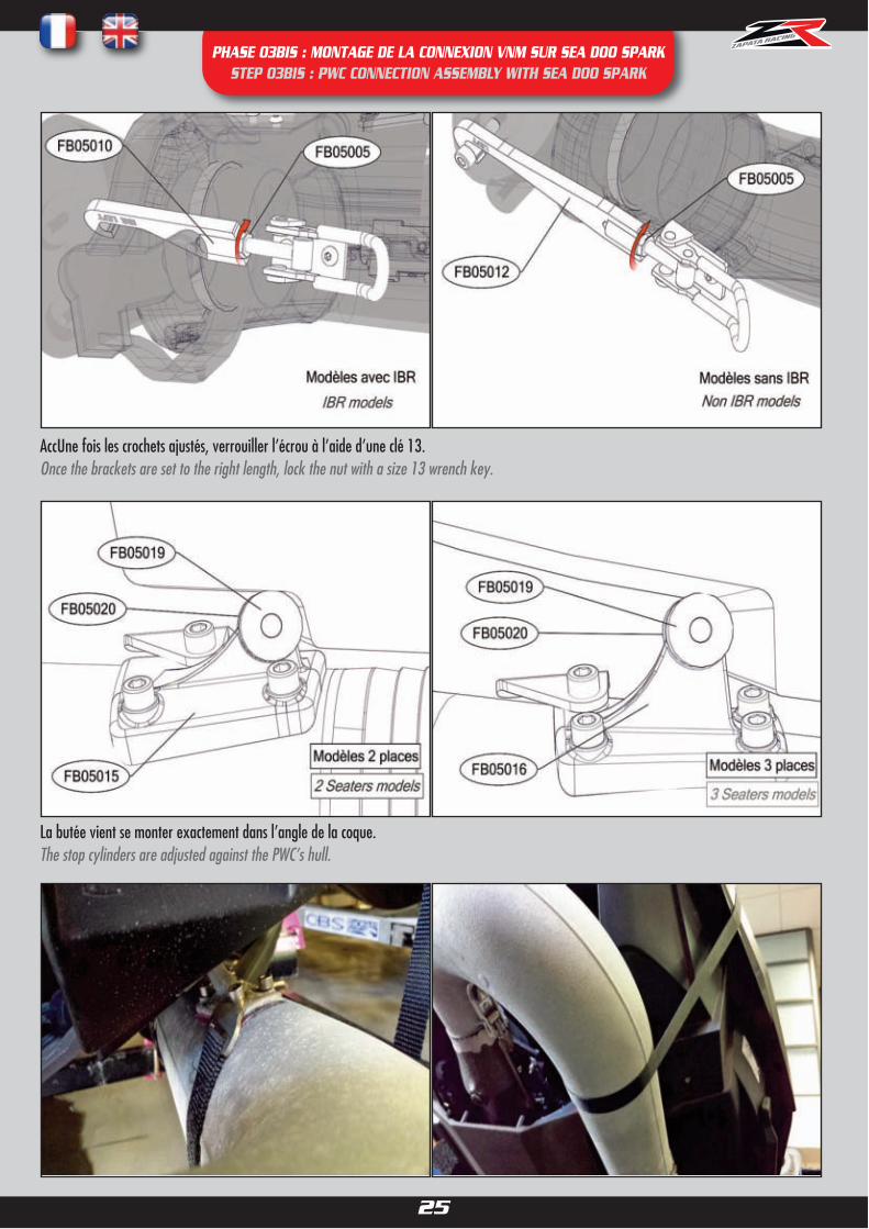
PHASE 03BIS : MONTAGE DE LA CONNEXION VNM SUR SEA DOO SPARK STEP 03BIS : PWC CONNECTION ASSEMBLY WITH SEA DOO SPARK
Utiliser le support adapté à votre modèle du Sea Doo Spark et assemblez les rondins réf. FB05019 et FB05020 à l’aide de la vis réf. FB05008et d’une clé Allen de 6.Use the mount that is relevant to your model of the Sea Doo Spark and assemble the stop cylinders ref. FB05019 and FB05020 with the screwref. FB05008 and a size 6 Allen key.
Monter la fixation réf. FB05015 ou FB05016 à l’aide des vis fournies (réf. FB05001) sur l’emplacement adéquat (selon modèle) du coude desortie à l’aide d’une clé Allen de 5 en prenant soin de monter la fixation de la sangle (réf. FB05004) dans l’emplacement adéquat.Assemble the mount ref. FB05015 or FB05016 using the screws ref. FB05001 on the relevant space of the U-pipe using a size 5 Allen key, ma-king sure that the strap holder (ref. FB05004) is assembled in the process.
2.Montage du support butéeAssembly of the mount
Le système de montage compatible Sea Doo Spark se monte sur les modèles 2 et 3 places, avec et sans IBR.Nous recommandons une puissance de 90CV.The assembly system compatible with Sea Doo Spark can be assembled to the 2 and 3 seaters models, with and without IBR.We recommend 90HP power.
1.Montage de la butée coque sur le support adéquatAssembly of the stop cylinders on the relevant mount
Vous trouverez deux supports disponibles pour monter les butées réf. FB05019 et FB05020. Le support réf. FB05015 a 3 trous et sera utilisépour les modèles 2 places et le support réf. FB05016 a 4 trous et sera utilisé pour les modèles 3 places.You will find two mounts for assembly of the stops ref. FB05019 and FB05020. The mount ref. FB05015 has 3 holes and will be used with 2 sea-ters models, and the mount ref. FB05016 has 4 holes and will be used with 3 seaters models.

20
PHASE 03BIS : MONTAGE DE LA CONNEXION VNM SUR SEA DOO SPARK STEP 03BIS : PWC CONNECTION ASSEMBLY WITH SEA DOO SPARK
Boucher l’emplacement laissé libre avec les vis réf. FB05002 et une clé Allen de 4 pour éviter une fuite d’eau et donc une perte de puissance.Plug in the space left empty with the screws ref. FB05002 and a size 4 Allen key to avoid water leakage (leading to a loss of power).
3.Modification VNMPWC Modifications
a. Modèles avec IBR : Montage / démontage rapide de l’IBRIBR Models : Quick assembly / unassembly of IBR
Retirer le boulon M8 de la fixation de la cloche IBR à l’aide d’une clé 13. Ceci empêchera la cloche de redescendre automatiquement lorsque lecoude sera en place.Remove the M8 screw from the IBR cover with size 13 key. This will stop the cover from coming down automatically when the U-Pipe will be in place.

21
PHASE 03BIS : MONTAGE DE LA CONNEXION VNM SUR SEA DOO SPARK STEP 03BIS : PWC CONNECTION ASSEMBLY WITH SEA DOO SPARK
Remplacer le boulon par le doigt d’indexage réf. FB05A02 et le remonter dans la cloche comme ci-dessus, pour garder l’IBR activé. Le doigt d’in-dexage permet d’activer (doigt d’indexage dans la cloche) ou de désactiver (doigt d’indexage retiré) rapidement l’IBR selon si l’utilisateur sou-haite utiliser sont VNM avec ou sans Jet Pack by ZR.Replace the screw with the index pin ref. FB05A02 and place it inside the cover as shown above, in order to keep the IBR working. The index pincan be inserted or removed to activate or deactivate the IBR depending on the user’s wish to use his PWC with Jet Pack by ZR (index pin remo-ved) or not (index pin inserted in the cover).
Nous utiliserons seulement les emplacements en haut à gauche et en bas à droite.We will only use the top left and bottom right slots.
Visser les boulons réf. FB05009 dans les emplacements en jaune. Screw the bolts ref. FB05009 in the yellow slots.
b. Modèles sans IBR : Fixation au nozzle d’origineNon IBR Models : attachment to the original nozzle
Localiser le nozzle fixe du VNM, en particulier les emplacements ci-dessous:Localize the PWC’s fixed nozzle, especially the slots in yellow :

22
PHASE 03BIS : MONTAGE DE LA CONNEXION VNM SUR SEA DOO SPARK STEP 03BIS : PWC CONNECTION ASSEMBLY WITH SEA DOO SPARK
4. Montage des crochets de fixation
Monter les crochets réf. FB05010 et FB05011 (avec IBR) ou FB05012 et FB05013 (sans IBR) en respectant bien les côtés droit et gauche.Assemble the brackets ref FB05010 and FB05011 (IBR) or FB05012 and FB05013 (non IBR) making sure right and left are used in the right location.
Faire approximativement une dizaine de tours de chaque côtéTurn the brackets approximately 10 times on each side

23
PHASE 03BIS : MONTAGE DE LA CONNEXION VNM SUR SEA DOO SPARK STEP 03BIS : PWC CONNECTION ASSEMBLY WITH SEA DOO SPARK
Insérer l’extrémité du coude dans le nozzle directionnel et l’emboîter au fond.Insert the u-pipe inside the directional nozzle.

24
PHASE 03BIS : MONTAGE DE LA CONNEXION VNM SUR SEA DOO SPARK STEP 03BIS : PWC CONNECTION ASSEMBLY WITH SEA DOO SPARK
Accrocher les crochets de fixation sur la barre de l’IBR de chaquecôté et fermer les attaches.Hook the brackets onto the IBR bar and close the fasteners.
Attention le coude doit être fermement fixé. Si ce n’est pas le cas, visser chaque crochet un tour supplémentaire. Lorsque le crochet droit est fermé, le crochet gauche doit se positionner naturellement à 45°. Si ce n’est pas le cas, il sera nécessaire d’ajuster le serrage.Le serrage doit être équivalent des deux côtés pour que le coude soit bien positionné. Un serrage inégal créera des fuites et une perte de puissancede 5% à 10%.Important: the U-pipe must be firmly attached. If not, each bracket must me given an extra turn.When the right fastener is closed, the left one must position itself naturally at a 45° angle. If not, it will be necessary to adjust further.In order for the u-pipe to be in place, it must be equally tight on both sides. If not, water leakage may occur and will cause a loss of powerof 5% to 10%.
Accrocher les crochets de fixation sur les boulons réf. FB05009et fermer les attaches.Hook the brackets onto the bolts ref. FB05009 and close the fasteners.
25
PHASE 03BIS : MONTAGE DE LA CONNEXION VNM SUR SEA DOO SPARK STEP 03BIS : PWC CONNECTION ASSEMBLY WITH SEA DOO SPARK
AccUne fois les crochets ajustés, verrouiller l’écrou à l’aide d’une clé 13.Once the brackets are set to the right length, lock the nut with a size 13 wrench key.
La butée vient se monter exactement dans l’angle de la coque. The stop cylinders are adjusted against the PWC’s hull.

26
PHASE 03BIS : MONTAGE DE LA CONNEXION VNM SUR SEA DOO SPARK STEP 03BIS : PWC CONNECTION ASSEMBLY WITH SEA DOO SPARK
Bien serrer à l’aide du cliquet. Faire en sorte que la sangle soit tendue aumaximum.Attention, si la sangle est mal tendue, il y a un risque d’endommager lesystème de direction du VNM. S’assurer que les rondins noirs sont enbutée de la coque et correctement positionnés et qu’il n’y ait aucun risquequ’ils bougent.
Tighten the strap firmly using the ratchet. Ensure the trap is tensed to itsmaximum.Warning, if the strap is not tightened enough, the steering system of thePWC is at risk of being damaged. Ensure that the black cylinders are tightlyagainst the hull and correctly positioned with no risk of moving.
Note : L’interface turbine FB03A08, les adaptateurs FB03KAF0x et Quick Nozzles FB03QNx ne pas nécessaires/compatibles avec ce système.
Note : The pump interface ref. FB03A08, adaptors ref. FB03KAF0x and Quick Nozzles ref. FB03QNx aren’t necessary/compatible with this system.

27
PHASE 04 : MONTAGE DE L’ENSEMBLE SANGLES/MOUSQUETON STEP 04 : ASSEMBLY OF THE STRAPS AND CARABINER
INSTRUCTIONS :
FB02022: Enfiler la sangle réf. FB02020 autour du tuyau d’alimentation. Passer la sangle réf. FB02022 dans le crochet d’attelage avant du VNM.
Attacher les deux sangles ensemble à l’aide du mousqueton FB02021.
FB02022: Slip the strap ref. FB02020 over the supply hose. Put the strap FB02022 through the front towing hook of the PWC. Lock the two straps
together with the carabiner ref. FB02021.

28
PHASE 05: MONTAGE DU PIVOT TUYAU STEP 05: HOSE SWIVEL ASSEMBLY
INSTRUCTIONS:
FB02003 : Enfiler les colliers réf. FB02003 sur le tuyau. Enfiler le tuyau sur le pivot tuyau réf. FB03A03 de manière à en
recouvrir les dents. Serrer les colliers à l’aide d’une clé 13 : couple de serrage 18 N/m
FB02003: Slip the clamps ref. FB02003 over the hose. Slip the hose over the hose swivel ref. FB03A03 until all teeth are
covered. Tighten the clamps with a size 13 key: torque 18 N/m

29
PHASE 06 : MONTAGE DES BRAS STEP 06 : ARMS ASSEMBLY
Instructions : Insérer le tube du bras gauche réf. JP01002 dans le support réf. JP01025. Se référer à l'illustration ci- dessous pour insérer les tubes dans le bon
sens. Pré-serrer la vis réf. JP01027 à l’aide d’une clé Allen de 4. Régler ensuite la position des bras au plus près du corps (voir ci-dessous) et serrer les vis à
8N.m avec la clé Allen de 4 (couple à respecter impérativement sous peine de casser le matériel). Répéter de l’autre côté.
Insert the left arm’s tube ref. JP01002 in the housing ref. JP01025. Please refer to the picture below to assemble the tubes the right way around. Start
tightening the screw ref. JP01027 with a size 4 Allen key. Adjust the position of the arms according to your preferences (see below) and finish tightening the screws ref. JP01027 with the size 4 Allen key (torque 8N.m must be respected in order to avoid breaking the equipment).Repeat on the other side.

30
Phase 07 : Montage des supports poignée Step 07 : Handle housing assembly
Insérer l’extrêmité du tube bras dans le support poignée.Insert the end of the arm tube inside the handle housing
Verrouiller les vis réf. JP01009 à l’aide d’une clé Allen de 4 (serrage à 4 N.m , à respecter impérativement sous peine d’endommager sérieusement le matériel).Lock the screws ref. JP01009 with a size 4 Allen key (torque 4 N.m, which must be respected, in order to avoid damaging the equipment).

31
PHASE 08: MONTAGE DES BAGUES DE BUSES STEP 08: ASSEMBLY OF THE NOZZLES’ RINGS
Instructions :
Installer la bague Ø61mm réf. FB04044 à l’extrémité de la buse réf. FB04042 et visser les deux vis réf. FB04060 à l’aide d’une clé Allen de 2. Répéter de l’autre côté.Install the Ø61mm ring ref. FB04044 at the end of the nozzle ref FB04042 and tighten both screws ref. FB04060 with a size 2 Allen key. Repeat on the other side.
Utilisation sans bagues de busesRemoving the swivel rings
Si l’utilisateur venait à ressentir des vibrations (par exemple avec des VNM de puissance supérieure à 215CV sans double hélice), les bagues peuventêtre retirées pour augmenter le diamètre de la buse à 62mm et ainsi se débarrasser des vibrations.
If the user was to feel vibrations (for example with a PWC with over 215HP power without a dual impeller), the rings can be removed to increasethe swivel’s diameter to 62mm, which stops all vibrations.
Instructions
Retirer les deux vis réf. FB04060 à l’aide d’une clé Allen de 2 et retirer la bague Ø61mm réf. FB04044. Répéter de l’autre côté.Remove both screws ref. FB04060 with a size 2 Allen key and remove the Ø61mm ring ref. FB04044. Repeat on the other side.
Le Jet Pack by ZR est livré avec des bagues de buses de Ø61mm (réf. FB04044) qui conviennent à la plupart des VNM.
The Jet Pack by ZR is supplied with standard Ø61mm swivel rings (ref. FB04044) that are suitable for most PWCs.

32
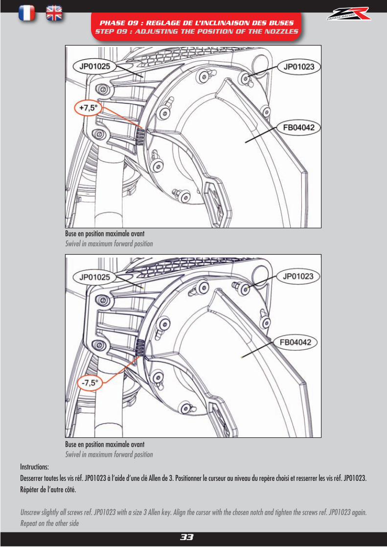
PHASE 09 : REGLAGE DE L’INCLINAISON DES BUSES STEP 09 : ADJUSTING THE POSITION OF THE NOZZLES
Il est possible de régler l’inclinaison des buses réf. FB04042 selon les préférences personnelles de l’utilisateur.It is possible to adjust the angle of the nozzles ref. FB04042 depending on the user’s preferences.
Le Jet Pack by ZR est livré avec en position 1 (+7.5°). Il est possible de régler les buses à jusqu’à -7.5°.The Jet Pack by ZR is supplied with the nozzles in position 1 (+7.5°). It is possible to adjust the nozzle up to -7.5°.
Position 1 Position 2
Pour changer l’inclinaison, faire pivoter la buse pour l’aligner sur l’un des repères disponibles.To change the angle, tilt the swivel to align with one of the available notches.
33
PHASE 09 : REGLAGE DE L’INCLINAISON DES BUSES STEP 09 : ADJUSTING THE POSITION OF THE NOZZLES
Instructions:Desserrer toutes les vis réf. JP01023 à l’aide d’une clé Allen de 3. Positionner le curseur au niveau du repère choisi et resserrer les vis réf. JP01023.Répéter de l’autre côté.
Unscrew slightly all screws ref. JP01023 with a size 3 Allen key. Align the cursor with the chosen notch and tighten the screws ref. JP01023 again.Repeat on the other side
Buse en position maximale avantSwivel in maximum forward position
Buse en position maximale avantSwivel in maximum forward position
34
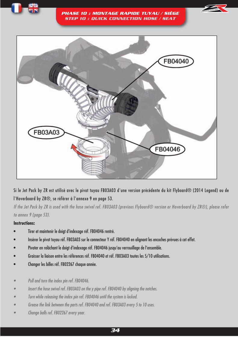
PHASE 10 : MONTAGE RAPIDE TUYAU / SIÈGE STEP 10 : QUICK CONNECTION HOSE / SEAT
Si le Jet Pack by ZR est utilisé avec le pivot tuyau FB03A03 d'une version précédente du kit Flyboard® (2014 Legend) ou de
l'Hoverboard by ZR®, se référer à l'annexe 9 en page 53.
If the Jet Pack by ZR is used with the hose swivel ref. FB03A03 (previous Flyboard® version or Hoverboard by ZR®), please refer
to annex 9 (page 53).
Instructions:
• Tirer et maintenir le doigt d’indexage réf. FB04046 rentré.
• Insérer le pivot tuyau réf. FB03A03 sur le connecteur Y réf. FB04040 en alignant les encoches prévues à cet effet.
• Pivoter en relâchant le doigt d’indexage réf. FB04046 jusqu’au verrouillage de l’ensemble.
• Graisser la liaison entre les références réf. FB04040 et réf. FB03A03 toutes les 5/10 utilisations.
• Changer les billes réf. FB02267 chaque année.
• Pull and turn the index pin ref. FB04046.
• Insert the hose swivel ref. FB03A03 on the y pipe ref. FB04040 by aligning the notches.
• Turn while releasing the index pin ref. FB04046 until the system is locked.
• Grease the link between the parts ref. FB04040 and ref. FB03A03 every 5 to 10 uses.
• Change balls ref. FB02267 every year.

35
PHASE 11 : RÉGLAGE DES SANGLES STEP 11 : ADJUSTING THE STRAPS
1. Ajuster la sangle avant réf. JP01006 afin que la boucle setrouve au niveau du nombril.Tighten or loosen the front strap ref. JP01006 so the quick releasebuckle is near the navel.
2 .Insérer les attaches des sangles des épaules réf. JP01004dans la boucle.Insert the tongues of the shoulder straps JP01004 in the quick re-lease buckle.
3. Ajuster les sangles des épaules afin d’être bien maintenu dans le siège.Tighten or loosen the shoulder straps so you are well maintained in the seat.
5. Serrer les sangles ventrales, s’assurer qu’elles sont bien serrées pour un maintien maximum. Un mauvais maintien fait glisser l’utilisateurvers l’avant, ce qui entraîne une pression trop importante par la sangle avant au niveau de l’entre-jambesTighten the waist straps, ensure they are tight for maximum support. Bad support will let the user slip forward, which would cause the frontstrap to put an uncomfortable pressure on the crotch.
4 .Insérer les attaches des sangles ventrales dans la boucle.Insert the tongues of the waist straps in the quick release buckle.

36
PHASE 11 : RÉGLAGE DES SANGLES STEP 11 : ADJUSTING THE STRAPS
Faire pivoter la boucle pour larguer le harnais.Twist the quick release buckle to release the straps.
Largage du harnaisFast Release
Le harnais se largue sans aucun effort.The straps are released instantly.

37
PHASE 12 : INSTALLATION DE LA TELECOMMANDE EMK (OPTIONNEL) STEP 12 : WIRELESS REMOTE ASSEMBLY (OPTIONAL)
Desserrer les vis réf. JP01009 à l’aide d’une clé Allen de 4 (visuel). Retirer la poignée réf. JP01010 (du côté où vous souhaitez utiliser la télécom-mande) et la garder pour une utilisation ultérieure.
Note : la télécommande est généralement utilisée du côté droit mais il est possible de l’utiliser du côté gauche selon les préférences personnelles de l’utilisateur.Untighten screw ref. JP01009 with a size 4 Allen key. Remove the handle ref. JP01010 (on the side where you wish to use the remote control) and
keep it for future use.Note : the remote control is usually used on the right side, but it is possible to use it on the left side depending on the user’s preference.
Pour la première installation, retirer le bouchon du support pile de la télécommande sans fil.For the first installation, remove the battery compartment cap of the wireless remote control.

38
PHASE 12 : INSTALLATION DE LA TELECOMMANDE EMK (OPTIONNEL) STEP 12 : WIRELESS REMOTE ASSEMBLY (OPTIONAL)
Visser l’adaptateur (réf. JP01032 vendu séparément) dans la télécommande.Screw in the adaptor (ref. JP01032, sold separately).
Pour retirer la télécommande (pour changer les piles, ou l’utiliser avec un autre produit ZR®) il suffit de la dévisser. Remettre le bouchon du sup-port pile, et remonter la poignée d’origine réf. JP01010 le cas échéant.
To remove the wireless remote control (to change the batteries, or for use with another ZR® product), simply unscrew it. If necessary, put the bat-tery compartment cap back on, and reassemble the original handle ref. JP01010.
Insérer l’ensemble dans l’attache poignée réf. JP01007.Insert the assembly into the handle housing ref. JP01007
Positionner la télécommande à l’angle qui parait le plus confortable etsans bouger la position resserrer les vis réf. JP01009 à l’aide d’une cléAllen de 4 (serrage très léger, à respecter impérativement pour ne pas
abîmer le matériel).Position the handle at the angle that feels most comfortable, andtighten the screws ref. JP01009 with the size 4 Allen key to lock itinto this position (very light tightening, which must be respected in
order to avoid damaging the equipment).

39
PHASE 13 INSTALLATION DU QUICK NOZZLE (OPTIONNEL) STEP 13 : QUICK NOZZLE INSTALLATION (OPTIONAL)
Le Quick Nozzle est un nozzle de VNM compatible avec l’interface turbine Flyboard® (réf. FB03A08) permettant de remonter la direction deson VNM en quelques secondes sans devoir remonter le nozzle d’origine.The Quick Nozzle is a PWC nozzle compatible with the Flyboard® pump interface (ref. FB03A08) that allows the user to use the steering of thePWC in seconds as opposed to assembling the original nozzle back to the PWC.
FB03219 : Sortir la partie mâle (boule) de la partie femelle. Visser la rotule mâle sur la partie directionnelle du sous ensemble nozzle réf.FB03QN sur le dessus ou le dessous de la patte de direction (selon le modèle de VNM), afin que le câble de direction du VNM reste dans sonaxe autant que possible.Remove the male part (ball) from the female part. Screw the male part onto the mobile part of the nozzle ref. FB03QN, on the top or bottom ofthe directional handle (depending on your PWC model), so the steering cable remains in its axis as much as possible.
FB02217: Visser dans la partie femelle de la rotule rapide réf. FB03219 et monter sur le câble de direction à la place de la rotule d’origine (voir photo).Screw inside the female part of the quick ball ref. FB03219 and mount onto the steering cable in place of the original quick ball (see photo).
FB03219 : Remonter la partie mâle et la partie femelle ensemble.Reassemble the male and female part together
Non compatible/nécessaire avec le Jet Pack by ZR Sea Doo Spark : réf. JP02000, JP02000L, JP02600, JP02600LNon compatible/necessary with Sea Doo Spark Jet Pack by ZR : ref. JP02000, JP02000L, JP02600, JP02600L
FB03QN1 :MODELE SEA DOOSEA DOO MODEL
REF. QT DESIGNATIONFB03QN 1 SOUS ENSEMBLE NOZZLE NOZZLEFB02217 1 ADAPTATEUR ROTULE SEADOO SEADOO SPACERFB03219 1 ROTULE RAPIDE QUICK BALL

40
PHASE 13 : INSTALLATION DU QUICK NOZZLE (OPTIONNEL) STEP 13 : QUICK NOZZLE INSTALLATION (OPTIONAL)
FB03219 : Visser la rotule sur la partie directionnelle du sous ensemble nozzle réf. FB03QN sur le dessus ou le dessous de la patte de direction(selon le modèle de VNM), afin que le câble de direction du VNM reste dans son axe autant que possible.Screw the quick ball onto the mobile part of the nozzle ref. FB03QN, on the top or bottom of the directional handle (depending on your PWCmodel), so the steering cable remains in its axis as much as possible.
FB03218: Visser dans la partie femelle de la rotule rapide réf. FB03219 et monter sur le câble de direction à la place de la rotule d’origine(voir photo).Screw inside the female part of the quick ball ref. FB03219 and mount onto the steering cable in place of the original quick ball (see photo).
FB03219 : Remonter la partie mâle et la partie femelle ensemble.Reassemble the male and female part together
Non compatible/nécessaire avec le Jet Pack by ZR Sea Doo Spark : réf. JP02000, JP02000L, JP02600, JP02600LNon compatible/necessary with Sea Doo Spark Jet Pack by ZR : ref. JP02000, JP02000L, JP02600, JP02600L
FB03QN2 : MODELE SEA DOO 2010SEA DOO 2010 MODEL
REF. QT DESIGNATIONFB03QN 1 SOUS ENSEMBLE NOZZLE NOZZLEFB03218 1 ADAPTATEUR ROTULE SEADOO 2010 SEADOO 2010 ADAPTATEUR BALLFB03219 1 ROTULE RAPIDE QUICK BALL

41
PHASE 13 INSTALLATION DU QUICK NOZZLE (OPTIONNEL) STEP 13 : QUICK NOZZLE INSTALLATION (OPTIONAL)
FB03219 : Visser la rotule sur la partie directionnelle du sous ensemble nozzle réf. FB03QN sur le dessus ou le dessous de la patte de direction(selon le modèle de VNM), afin que le câble de direction du VNM reste dans son axe autant que possible.Screw the quick ball onto the mobile part of the nozzle ref. FB03QN, on the top or bottom of the directional handle (depending on your PWCmodel), so the steering cable remains in its axis as much as possible.
FB02225: Visser dans la partie femelle de la rotule rapide réf. FB03219 et monter sur le câble de direction à la place de la rotule d’origine(voir photo).Screw inside the female part of the quick ball ref. FB03219 and mount onto the steering cable in place of the original quick ball (see photo).
FB03219 : Remonter la partie mâle et la partie femelle ensemble.Reassemble the male and female part together
Non compatible/nécessaire avec le Jet Pack by ZR Sea Doo Spark : réf. JP02000, JP02000L, JP02600, JP02600LNon compatible/necessary with Sea Doo Spark Jet Pack by ZR : ref. JP02000, JP02000L, JP02600, JP02600L
FB03QN3 : MODELE KAWASAKI 15FKAWASAKI 15F MODEL
REF. QT DESIGNATIONFB03QN 1 SOUS ENSEMBLE NOZZLE NOZZLEFB02225 1 ADAPTATEUR ROTULE KAWASAKI 15F KAWASAKI 15F ADAPTATER BALLFB03219 1 ROTULE RAPIDE QUICK BALL

42
PHASE 13 : INSTALLATION DU QUICK NOZZLE (OPTIONNEL) STEP 13 : QUICK NOZZLE INSTALLATION (OPTIONAL)
FB03220 : Visser la rotule sur la partie directionnelle du sous ensemble nozzle réf. FB03QN sur le dessus ou le dessous de la patte de direction
(selon le modèle de VNM), afin que le câble de direction du VNM reste dans son axe autant que possible. Monter la partie femelle sur le câble de
direction à la place de la rotule d’origine (voir photo). Remonter la partie mâle et la partie femelle ensemble.
Screw the quick ball onto the mobile part of the nozzle ref. FB03QN, on the top or bottom of the directional handle (depending on your PWC
model), so the steering cable remains in its axis as much as possible. Mount the female part onto the steering cable in place of the original quick
ball (see photo). Reassemble the male and female part together
Non compatible/nécessaire avec le Jet Pack by ZR Sea Doo Spark : réf. JP02000, JP02000L, JP02600, JP02600L
Non compatible/necessary with Sea Doo Spark Jet Pack by ZR : ref. JP02000, JP02000L, JP02600, JP02600L
FB03QN4 : MODELE KAWASAKI ULTRAKAWASAKI ULTRA MODEL
REF. QT DESIGNATIONFB03QN 1 SOUS ENSEMBLE NOZZLE NOZZLEFB03220 1 ROTULE RAPIDE KAWASAKI ULTRA KAWASAKI ULTRA QUICK BALL

43
PHASE 13 : INSTALLATION DU QUICK NOZZLE (OPTIONNEL) STEP 13 : QUICK NOZZLE INSTALLATION (OPTIONAL)
FB03219 : Visser la rotule sur la partie directionnelle du sous ensemble nozzle réf. FB03QN sur le dessus ou le dessous de la patte de direction(selon le modèle de VNM), afin que le câble de direction du VNM reste dans son axe autant que possible.Screw the quick ball onto the mobile part of the nozzle ref. FB03QN, on the top or bottom of the directional handle (depending on your PWCmodel), so the steering cable remains in its axis as much as possible.
FB03222: Visser dans la partie femelle de la rotule rapide réf. FB03219 et monter sur le câble de direction à la place de la rotule d’origine(voir photo).Screw inside the female part of the quick ball ref. FB03219 and mount onto the steering cable in place of the original quick ball (see photo).
FB03219 : Remonter la partie mâle et la partie femelle ensemble.Reassemble the male and female part together
Non compatible/nécessaire avec le Jet Pack by ZR Sea Doo Spark : réf. JP02000, JP02000L, JP02600, JP02600LNon compatible/necessary with Sea Doo Spark Jet Pack by ZR : ref. JP02000, JP02000L, JP02600, JP02600L
REF. QT DESIGNATIONFB03QN 1 SOUS ENSEMBLE NOZZLE NOZZLEFB03222 1 ADAPTATEUR ROTULE YAMAHA YAMAHA SPACERFB03219 1 ROTULE RAPIDE QUICK BALL
FB03QN5 : MODELE YAMAHAYAMAHA MODEL

44
PHASE 13 : INSTALLATION DU QUICK NOZZLE (OPTIONNEL) STEP 13 : QUICK NOZZLE INSTALLATION (OPTIONAL)
FB03219 : Visser la rotule sur la partie directionnelle du sous ensemble nozzle réf. FB03QN sur le dessus ou le dessous de la patte de direction(selon le modèle de VNM), afin que le câble de direction du VNM reste dans son axe autant que possible.Screw the quick ball onto the mobile part of the nozzle ref. FB03QN, on the top or bottom of the directional handle (depending on your PWCmodel), so the steering cable remains in its axis as much as possible.
FB03234: Visser dans la partie femelle de la rotule rapide réf. FB03219 et monter sur le câble de direction à la place de la rotule d’origine(voir photo).Screw inside the female part of the quick ball ref. FB03219 and mount onto the steering cable in place of the original quick ball (see photo).
FB03219 : Remonter la partie mâle et la partie femelle ensemble.Reassemble the male and female part together.
Non compatible/nécessaire avec le Jet Pack by ZR Sea Doo Spark : réf. JP02000, JP02000L, JP02600, JP02600LNon compatible/necessary with Sea Doo Spark Jet Pack by ZR : ref. JP02000, JP02000L, JP02600, JP02600L
REF. QT DESIGNATIONFB03QN 1 SOUS ENSEMBLE NOZZLE NOZZLEFB03234 1 ADAPTATEUR ROTULE HONDA HONDA SPACERFB03219 1 ROTULE RAPIDE QUICK BALL
FB03QN6 : MODELE HONDAHONDA MODEL

45
ANNEXE 1 : SIÈGE JET PACK BY ZRANNEX 1 : JET PACK BY ZR SEAT

46
ANNEXE 1 : SIÈGE JET PACK BY ZRANNEX 1 : JET PACK BY ZR SEAT
REF. QT DESIGNATION
JP01001 1 SIEGE SEAT
JP01002 1 BRAS GAUCHE LEFT ARM
JP01003 1 BRAS DROIT RIGHT ARM
JP01004 2 ENSEMBLE SANGLES EPAULES SHOULDER STRAPS
JP01005 2 ENSEMBLE SANGLES VENTRALES WAIST STRAP
JP01006 1 ENSEMBLE SANGLE AVANT + ATTACHE FRONT STRAP
JP01007 2 ATTACHE POIGNEES HANDLE LOCKING SYSTEM
JP01008 12 ECROU M5 M5 NUT
JP01009 8 VIS CHC M5 X 20 M5*20 SCREW
JP01010 2 POIGNEE HANDLE
JP01011 2 BOUCHON POIGNEE HANDLE CAP
JP01012 2 TUBE POIGNEE HANDLE TUBE
JP01013 1 ENTRETOISE POM POM SPACER
JP01014 1 PONTET BRIDGE
JP01015 3 VIS BHC AVEC COLERETTE M6 X 20 SPECIAL SCREW
JP01016 1 PLASTRON ALU ALUMINUM TRIANGLE PLATE
JP01017 1 PONTET ARRIERE BACK BRIDGE
JP01018 4 VIS CHC M6 X 45 M6 X 45 SCREW
JP01019 3 VIS TCB TORX M4 X 16 M4 X 16 SCREW
JP01020 1 VIS BHC M8 X 70 M8 X 70 SCREW
JP01021 1 BARRE DE TORSION TORSION BAR
JP01022 1 PLASTRON ROUGE RED TRIANGLE PLATE
JP01023 16 VIS FHC M5 X 50 M5 X 50 SCREW
JP01024 2 JOINT TORIQUE SUPPORT BRAS ARM HOUSING O-RING
JP01025 2 SUPPORT BRAS ARM HOUSING
JP01026 4 VIS PLASTITE M5 X 20 M5 X 20 SCREW
JP01027 4 VIS CHC M5 X 25 M5 X 25 SCREW
JP01028 2 JOINT ROULEMENT BEARING O-RING
JP01029 16 ECROU RELAI M5 RELAY NUT
JP01030 2 ROULEMENT BEARING
JP01031 16 VIS HEXA M5 X 70 M5 X 70 SCREW
FB04040 1 CONNECTEUR Y Y PIPE
FB04041 2 BRIDE ROULEMENT BEARING RING
FB04042 2 BUSE (DROITE ET GAUCHE) NOZZLE (LEFT AND RIGHT)
FB04052 16 RONDELLE CUVETTE M5 DECOLLETEE SPECIAL WASHER
FB04060 4 VIS BHC 3 X 12 SCREW M3*12
FB04070 2 BAGUE ETANCHEITE ROULEMENT SEALING RING
FB02267 122 BILLE PLASTIQUE PLASTIC BALL
FB04044 2 BAGUE BUSE Ø61 NOZZLE RING Ø61
FB04071 2 JOINT TORIQUE BUSE NOZZLE O-RING
FB04093 2 JOINT TORIQUE BAGUE BUSE SWIVEL RING O-RING
FB04046 1 DOIGT D'INDEXAGE Y Y PIPE INDEX PIN
FB04047 1 RESSORT INDEXAGE Y Y PIPE INDEX PIN SPRING
FB04048 1 ANNEAU INDEXAGE Y Y PIPE INDEX PIN RING

47
ANNEXE 2 : FB03A01- COUDE DE SORTIEANNEX 2 : FB03A01 - U PIPE
REF. QT DESIGNATIONFB02012 4 VIS CHC M10X50 SCREW CHC M10X50FB02013 4 ECROU H M10 NUT H M10FB03026 4 VIS DE BAGUE DE SORTIE RING SCREWFB03011 1 BAGUE COUDE DE SORTIE U PIPE RINGFB02014 1 DOIGT D’INDEXAGE INDEX PINFB03010 1 COUDE DE CONNECTION U PIPEFB03024 1 BUSE COUDE U PIPE NOZZLEFB03023 1 BOUCHON BUSE NOZZLE CAPFB02011 1 BOUCHON COUDE U PIPE CAP
Non inclus dans le Jet Pack by ZR Sea Doo Spark : réf. JP02000/JP02600 Not included in Sea Doo Spark Jet Pack by ZR : ref. JP02000/JP02600

ANNEXE 3 : FB05A01- COUDE DE SORTIE SEA DOO SPARKANNEX 3 : FB05A01 – SEA DOO SPARK U PIPE
REF. QT DESIGNATIONFB05001 4 Vis support rondin Mount screwFB05002 4 Vis de bouchage Plugging screwFB05003 1 Rondelle pour doigt d'indexage Index pin ringFB05004 1 Sangle complète Complete strapFB05005 2 Sauterelle à crochet FastenerFB05007 4 Vis sauterelle Fastener screwFB05008 1 Vis rondin Cylinder screwFB05009 2 Vis attache crochets non IBR Fixation boltFB05010 1 Crochet IBR Gauche Left bracket (IBR)FB05011 1 Crochet IBR Droit Right bracket (IBR)FB05012 1 Crochet non IBR gauche Left bracket (non IBR)FB05013 1 Crochet non IBR droit Right bracket (non IBR)FB05014 2 Entretoise non IBR Fixation spacerFB05015 1 Support Rondin 3 trous 3 holes mountFB05016 1 Support Rondin 4 trous 4 holes mountFB05017 1 Mousqueton CarabinerFB05018 1 Coude compatible Spark non équippé Spark compatible u-pipe (non assembled)FB05019 1 Rondin Taraudé Threaded cylinderFB05020 1 Rondin Percé Drilled holeFB05021 1 Bague noire Black ringFB05022 1 Tube TubeFB05023 1 Doigt d'indexage Index pinFB05025 1 Entretoise doigt d'indxage
48
Index pin spacer

49
ANNEXE 4: FB03A08: INTERFACE TURBINEANNEX 4: FB03A08 – PUMP INTERFACE
REF. QT DESIGNATION
FB03001 1 INTERFACE TURBINE PUMP INTERFACE
FB03028 1 DURITE VENTURI VENTURI PIPE
FB03019 1 CANNELURE VENTURI VENTURI GROOVE
FB03038 2 VIS DE CAPOT COVER SCREW
FB03036 1 CAPOT VENTURI VENTURI COVER
FB03037 1 FILTRE VENTURI VENTURI FILTER
FB03027 1 MAMELON TUBE CANNELE SPLINED TUBE NIPPLE
FB03029 1 TUBE CANNELE SPLINED TUBE
Non incluse dans le Jet Pack by ZR Sea Doo Spark : réf. JP02000/JP02600 Not included in Sea Doo Spark Jet Pack by ZR : ref. JP02000/JP02600

50
ANNEXE 5 : FB03A03 - PIVOT TUYAU ANNEX 5 : FB03A03 - HOSE SWIVEL
REF. QT DESIGNATION
FB04094 1 JOINT TORIQUE O-RING
FB02030 1 AXE PIVOT TUYAU HOSE BEARING SHAFT
FB02034 3 VIS BUTEE M4X6 SCREW M4X6
FB02267 39 BILLE PLASTIQUE PLASTIC BALL
FB03033 1 CORPS PIVOT TUYAU HOSE BEARING BODY

51
ANNEXE 6 : JP01A07 - KIT ACCESSOIRES JET PACK BY ZRANNEX 6 : JP01A07 - JET PACK BY ZR ACCESSORIES KIT
REF. QT DESIGNATION
FB02003 4 COLLIER DE SERRAGE 0104 – 112 CLAMP 0104 – 112
FB02020 1 SANGLE TUYAU HOSE STRAP
FB02021 1 MOUSQUETON CARABINER
FB02022 1 SANGLE D’ATTACHE FASTENING STRAP
FB04060 4 VIS BHC M3*12 BHC SCREW M3*12
FB04044 2 BAGUE Ø61MM Ø61MM RING
REF REF

52
ANNEXE 7 : FB03QN – SOUS ENSEMBLE NOZZLE(OPTIONNEL)
ANNEX 7 : FB03QN - NOZZLE (OPTIONAL)
REF. QT DESIGNATION
FB02014 1 DOIGT D’INDEXAGE INDEX PIN
FB03026 4 VIS DE BAGUE DE SORTIE RING SCREW
FB03011 1 BAGUE COUDE DE SORTIE U PIPE RING
FB02013 4 ECROU HM10 NUT H M10
FB02012 4 VIS CHC M10X50 SCREW CHC M10 X50
FB02291 2 VIS CHC M8X10 SCREW CHC M8X10
FB03285 1 NOZZLE NOZZLE
FB03286 1 DIRECTIONNEL DIRECTIONAL NOZZLE
Non compatible/nécessaire dans le Jet Pack by ZR Sea Doo Spark : réf. JP02000/JP02600 Not compatilble/necessary in Sea Doo Spark Jet Pack by ZR : ref. JP02000/JP02600

53
ANNEXE 8 : COMMENT CHOISIR SON TUYAU JET PACK BY ZRANNEX 8 : HOW TO CHOOSE YOUR JET PACK BY ZR HOSE
Zapata Racing® propose plusieurs types de tuyaux d’alimentation pour s’adapter au mieux aux préférences de l’utilisateur. Zapata Racing® offers several hose types to adapt best to the user’s preferences
Le tuyau X-Armor (disponible en longueurs 18m (réf. ZR01003) et 23m (réf ZR01003-23)) est le plus performant de la gamme. Il a été conçu pour s’adapter àt outesl es situations.I l est extrêmement résistant et est construit d’une seule pièce pour évitert out risque de délamination1 . Son utilisation est recommandée dans le cadre d’une activité d’initiation ainsi que pour une utilisation par un particulier.Le tuyau X-Armor peut être utilisé avec un VNM de faible puissance type Sea Doo Spark (90CV). L’utilisation de ce tuyau dans sa version 23m apporte un confort d’utilisation supplémentaire car la distance de l’utilisateur par rapport au VNM s’en retrouve augmentée (voir pages 3, 4 et 5 pour les consignes de sécurité relatives à la vigilance de l’utilisateur par rapport à sa position relative au VNM). Le tuyau X-Armor est garanti contre tout défaut de fabrication et délamination (décollage entre les parois interne et externe du tuyau sur toute sa longueur).
The X-Armor hose (available in 18m length (ref. ZR01003) and 23m (ref. ZR01003-23)) is the best hose in the range. It is very versatile and was designed to adapt to any situation. It is extremely durable and built in once piece to avoid any risk of delamination1 . It is recommended for Flight Centers as well as private customers.The X-Armor hose can be used with small PWCs such as the Sea Doo Spark (90HP).
Using the 23m version oft his hose adds comfort due to the PWC being further away from the user (see pages 53-54-55 for safety advice in particular distance between PWC and Jet Pack by ZR user).The X-Armor Hose is covered by warranty against any manufacturing fault and delamination (inner and outer wall coming appart on the entire length of the hose).
Le tuyau Rider (réf. FB02002) a été conçu pour l’utilisation du kit Jet Pack by ZR pour un usage par un particulier. C’est le moins cher et le plus léger de la gamme, il est plus facile à transporter et à emballer. Il n’existe qu’en longueur 18m.Le tuyau Rider est une pièce d’usure qu’il faudra changer au moins tous les deux ans et n’est pas couvert par la garantie.The Rider Hose (ref. FB02002) was designed for private usage. It is the cheapest and the lightest in the range, it is easier to pack and carry. It only exists in 18m length.The Rider hose is subject to wear and tear that must be replaced at least once every two years and therefore is not covered by warranty.
Attention, le Jet Pack by ZR n’est pas compatible avec le tuyau X-Power (réf. ZR01002/ZR01002-23) de Zapata Racing®Warning, the Jet Pack by ZR is not compatible with the X-Power hose (réf. ZR01002/ZR01002-23) from Zapata Racing®
Se référer au tableau comparative ci-dessous : Please Refer to the comparative table below :
1) DELAMINATION : PHENOMENE QUI SE PRODUIT AVEC L’USURE DU TUYAU, ET D’AUTANT PLUS DANS LE CADRE D’UNE UTILISATION INTENSIVE (EX : LOCATION, COMPETITION, USAGE PERSONNEL…) D’UN MAUVAIS ENTRETIEN (EXPOSITION AU SOLEIL, STOCKAGE DU TUYAU NON RINCE ET/OU NON SECHE, MANIPULATION DU TUYAU SUR LA PLAGE LORSQU’IL EST PLEIN D’EAU ... ) OU D’UNEMAUVAISE UTILISATION (VIRAGE SERRES, VIRAGES A 360° SUIVIS D’UNE ACCELERATION BRUTALE (CREATION DE NŒUDS)) SE REFERER A LA PAGE 8 POUR LES INSTRUCTIONS D’ENTRETIEN ET A LAPAGE 4 POUR LES CONSEILS D’UTILISATION EN VOL.
2) DELAMINATION: OCCURS WITH WEAR OF THE HOSE, ESPECIALLY WHEN USED EXTENSIVELY (I.E.: FLY CENTERS, PRO LEVEL USE, PERSONAL USE …), WHEN BADLY MAINTAINED (EXPOSED TO DIRECTSUNLIGHT, STORED WET AND/OR WITHOUT RINSING, PULLED ON THE BEACH WHEN FULL OF WATER) OR WHEN MISUSED (TIGHT TURNS, 360° TURNS FOLLOWED WITH FAST ACCELERATIONS(CREATING KNOTS)). PLEASE REFER TO PAGE 56 FOR CARE AND MAINTENANCE
Nom / Name X-Armor X-Armor RiderLongueur (m) / Length (m) 18 23 18Réference / Reference ZR01003 ZR01003-23 FB02002Durabilité / Durability ****** ****** ***Sécurité (distance avec le VNM) *** **** ***Safety (distance from PWC)
Prix / Price Range $$ $

54
ANNEXE 9 - Modification du pivot tuyau FB03A03 existantANNEX 9 - Modification of a hose swivel
Si vous avez acheté Flyboard® Pro Series Standalone réfs. FB04B03 / FB04B03L / FB04B04 ou un Jet Pack by ZR® Standalone réf. JP01B03(version sans système d’adaptation au VNM pour connexion sur un système existant), il sera nécessaire de modifier le pivot tuyau existant.
If you have purchased Flyboard® Pro Series Standalone refs. FB04B03 / FB04B03L / FB04B04 or a Jet Pack by ZR® Standalone ref. JP01B03(versions without connection kit, for connecting on an existing kit), it will be necessary to modify the existing hose swivel.
Flyboard® Pro Series (standalone) et Jet Pack by ZR (standalone) sont fournis avec un joint torique (réf. FB04094), pour remplacer la bagued’usure réf. FB02031. Pour ceci, retirer la bague d'usure FB02031 (généralement collée avec un point de colle) et rouler le joint toriqueréf. FB04093 à la place.Flyboard® Pro Series (standalone) and Jet Pack by ZR (standalone) are supplied with a rubber O-ring (ref. FB04094), to replace the wear ringref. FB02031. For this, remove the wear ring ref. FB02031 (which is lightly glued to the swivel) and roll the O-ring ref. FB04094 down in itsplace.Si vous trouvez la connexion rapide entre le connecteur Y et votre pivot tuyau difficile, vous pouvez également percer les trous du doigt d’indexageréf. FB04046 à Ø4.5mm ce qui en facilitera l’insertion.If you find the quick connexion between the Y pipe and the hose swivel stiff, you can also drill the index pin’s holes with a size 16 bit, which willfacilitate the insertion of the index pin ref. FB04046.
FB03A03 : Pivot tuyau vendu avec Flyboard® 2014 (Legend) et Hoverboard by ZR®FB03A03 : Hose swivel sold with Flyboard® 2014 (Legend) and Hoverboard by ZR®

55
ANNEXE 10 - TRAITEMENT DU PROBLÈME DE VIBRATIONSANNEX 10 - SOLVING VIBRATION PROBLEMS
Si l’utilisateur ressent des vibrations en vol, ce n’est pas de la cavitation, mais ce sont des ondes néfastes qui perturbent le bon fonctionnement duJet Pack by ZR au niveau de la performance, du confort, mais aussi au niveau de la longévité des pièces mécaniques du Jet Pack by ZR et duVNM. Si le problème de vibrations est traité les performances seront augmentées.
If the user feels vibrations whilst flying, it is not cavitation, but they affect the performance, comfort and may damage mechanical parts on theJet Pack by ZR and the PWC. If the vibration problem is solved, performance will be improved.
En cas de vibrations :1ère étape : Retirer les bagues de buses réf. FB04044.
In case of vibrations :1st Step : Remove the nozzle rings ref. FB04044
2ème étape : Si le problème persiste, remplacer la bagued’usure du coude de connexion par les pièces réf. FB03102comme ci-dessous :
2nd Step: If the problem continues, replace the wear ringof the u-pipe with the parts ref. FB03102 (see below).
Les pièces réf. FB03102 sont incluses dans le Jet Pack by ZR.Dans le cas contraire contactez votre revendeur.
Parts ref. FB03102 are included the Jet Pack by ZR. If notplease contact your reseller.
Note : Si vous avez la version 2013 du coude de connexion, utilisezsimplement la bague d’usure courte réf. FB02274 fournie avec votreFlyboard®.Note : If your own the 2013 version of the U-Pipe, simply use theshort wear ring ref. FB02274 that was provided with your Flyboard®.
3ème étape : Si les vibrations persistent toujours, desser-rer les vis réf. FB02012 demi-tour par demi-tour jusqu’à ceque les vibrations disparaissent.
Important : la perte de puissance engendrée par la fuited’eau sera négligeable en rapport du gain de puissancecausé par la suppression des vibrations.
3rd Step : If the vibrations continue, slightly unscrew thescrews ref. FB02012 half a turn by half a turn, until vibra-tions stop.
Important: there will be a loss of power caused by thewater leakage, however it is negligible in comparison tothe power gained following these steps.
56
DESCRIPTION
The Jet Pack by ZR is a water powered device allowing the user to move both below the surface of the water and in the air.
The supply hose (which is connected to the pump of the PWC) is attached to a Y shaped pipe which roots the water through two nozzles placed near
the user’s shoulders. This generates thrust and allows the user to move by tilting his arms.
The Jet Pack by ZR is intuitive to use, but it is an extreme sport which requires to be practiced with vigilance. It was designed to be purely recreative
and accessible to everyone, not to make tricks or stunts.
95% of its parts are made in France.
SAFETY – RISKY BEHAVIOUR – GENERAL INFORMATION
It is recommended not to use the Jet Pack by ZR under the age of 16 (no weight restriction).
It is forbidden and dangerous to practice the Jet Pack by ZR when winds exceed 60 km/h and waves exceed 1 meter in height.
It is mandatory to follow an hour of training in a specialized fly center to understand the basics and the main security rules (please refer to the “ZR
Spots” section on www.zapata-racing.com.)
It is forbidden to use the Jet Pack by ZR under the influence of alcohol, narcotics or drugs which could affect alertness.
MANDATORY EQUIPMENT
- Life jacket with CE certification
- Wakeboard type helmet
- Neoprene shorts: the penetration of water through the orifices of the body during a fall or during contact with the Jet Pack by ZR water jets may
cause serious internal injuries. Wearing a simple bathing suit is not an adequate protection.
IMPORTANT
It is essential to comply with the navigation laws according to the country where the Jet Pack by ZR is used.
Make sure the area where the Jet Pack by ZR is practiced is cleared from any other watercraft such as boats, other PWC or other the Jet Pack by ZR
users as well as swimmers, divers and other sea users.
Before lifting up to 2 meters or more, and before diving: make sure there is a minimum depth of 4 meters and that the wateris clear enough to estimate the depth and the reliefs.
It is strongly recommended not to take off, land or use the Jet Pack by ZR near to any source of risk such as rocks, docks, beaches, boats, banks etc.
Misuse of the Jet Pack by ZR can result in serious injuries.
Do not exceed your limits and avoid aggressive movements to reduce loss of control.

57
This is a high performance product, not a toy.
Do not reproduce tricks and risky behavior such as showed on TV or Internet. These are performed by professionals. You risk serious injury, put your life in danger and risk to seriously damage the equipment if the tricks are not done perfectly.
Ensure any trajectory taken opposite the PWC is not too tight, but keep a radius curvature of 4 meters minimum. An aggressive turn leads the Jet Pack by ZR to over break and makes the PWC take an abrupt turn with the possible cases:- Fall of the Jet Pack by ZR user- Fall of the PWC driver- Breakage of the parts ref. FB02020 – FB02021 – FB02022- Damage the hose ref. FB02002 / ZR01002 / ZR01002-23 by either causing a separation between the inner and outer layer at the connection withthe strap, causing an immediate or delayed tear of the hose (this does not apply to the X-Armor hose ref ZR01003 / ZR01003-23).
Do not turn 360 ° in front of the watercraft as this may damage the hose ref. FB02002 / ZR01002 / ZR01002-23 by either causing a separationbetween the inner and outer layer of the hose at the connection with the strap, or causing an immediate or delayed tear of the hose (this does notapply to the X-Armor hose ref ZR01003 / ZR01003-23).
The Jet Pack by ZR user and the PWC driver must be sure the distance between the Jet Pack by ZR and the PWC is never less than 4 meters.
When the Jet Pack by ZR is used by 2 persons (without electronic kit – optional, see page 55), the watercraft driver mustn’t exceed 6000 RPM. It isrecommended to use the learning key when using a PWC over 250HP.The Jet Pack by ZR user and the PWC driver must be sure that the Jet Pack by ZR user has sufficient stability and does not fall on his back before anew step in height.

58
When falling into water, it is essential that the Jet Pack by ZR user or the watercraft driver releases the throttle as soon as possible and turns off the engine.When the Jet Pack by ZR user is underwater (fall or dive) the watercraft driver must immediately releases the throttle and turn the engine off. A minimum level in swimming is compulsory. The Jet Pack by ZR should not be used by water phobic people.When falling (especially on the back), the Jet Pack by ZR user can go up to a 2 meters depth underwater so he must anticipate an apnea of about 10 seconds during the fall and during immersion.Never take a path towards the PWC.Note : the Jet Pack by ZR bearings will be stiffer than normal for the first 10 minutes of use.
USING THE JET PACK BY ZR FOR THE FIRST TIME
It is mandatory to follow an hour of training in a specialized fly center to understand the basics and the main security rules (please refer to the “ZR Spots” section on www.zapata-racing.com.)When flying a novice person, the watercraft driver mustn’t exceed 4500 RPM. It is important not to accelerate if the user fails to take off because the user may be propelled in the air when positioning his feet flat.If the person fails to take off, it means his arms are not well positioned.
You can check this tutorial video for more detailed explanations : https://youtu.be/IX94qrgi8Lk?list=PLp9MhWWMIp3qv5f6T6csZa5k7aHWNwMHM
USING THE JET PACK BY ZR WITH EMK (OPTIONAL)
If the Jet Pack by ZR user uses the EMK for the first time, level 1 (learning mode) must be used first (only 1 LED lit) during 20 minutes at least.The user must train at each level for 20 minutes minimum before advancing to the next level. At the exception of level 4 which should never be usedbefore 5 hours of training at level 3, and level 5 which should never be used before 10 hours of training at level 4.
TYPE OF PWC
Any type of watercraft as long as is approved and certified by the authorities in the country where it is used.
- Power requirement: 100 HP- Maximum power requirements: 300 HP
Adaptors for Sea Doo, Yamaha, Kawasaki and Honda PWCs are available within the distribution network.
It is extremely dangerous and not recommended to remove the PWC buoyancy elements.
Correct position Incorrect position
59
ADAPTATION TO THE PWC
To connect the Jet Pack by ZR on the watercraft:a) Remove the steering and reverse systems.b) Assemble the pump interface (ref. FB03A08) with the appropriate adapter (PWC brand and model specific).
Adaptors are necessary for to allow assembly between the Jet Pack by ZR and the PWC. They are available through the distribution network, andcompatible with all main brands: Sea Doo, Yamaha, Kawasaki and Honda. As the adaptor is not included in the Jet Pack by ZR, please ensure yourdealer know which PWC brand and model you intend to use with the Jet Pack by ZR.
Adapting the Jet Pack by ZR on Sea Doo Spark:A specific adaptation system is available for the use of the Jet Pack by ZR with the Sea Doo Spark (2 or 3 seaters, with or without IBR, recommendedfor 90HP version). Please refer to page 18 for complete assembly instructions.
WHERE TO PRACTICE JET PACK BY ZR?
The Jet Pack by ZR can be used in both lakes and open seas when the minimum water depth of 4 meters is respected.It is strictly forbidden to use the Jet Pack by ZR in confined spaces such as swimming pools etc...Do not start the watercraft or use the Jet Pack by ZR in insufficient water depths (less than 1 meter) with sandy bottom, it may damage the Jet Packby ZR bearings.In the event of such use, check the operation of all bearings before further use to avoid breakage of the equipment.Warning, it is the responsibility of the user to make sure there is sufficient depth in the stretch of water used.
MAINTENANCE – AFTER SALES SERVICE
WARNING: NEVER use hydrocarbons like acetone or petrol on polycarbonate parts (all see-through parts) as these productscan seriously damage the material.
To ensure adequate security, we recommend to:• Check the all seat’s screws are tight after 2 hours of use.• Change the supply hose every 2 years.• Change the plastic balls ref. FB02267 of the Jet Pack by ZR seat ref. FB04B01 every year. Ensure to use silicone grease or Vaseline (no
marine grease or other product containing hydrocarbons that may damage the Jet Pack by ZR material).• Change the clips ref. FB02046 of the Jet Pack by ZR seat ref. FB04B01 every year.• Change the rings ref. FB04070, FB04071, FB04087, FB04094 and FB03011 every year.• the Jet Pack by ZR should be rinsed with clean water after each use (hose, seat) and stored in a dry location away from direct sunlight (this
does not apply to the X-Armor hose ZR01003 / ZR01003-23).• Do not pull the hose on the floor when full of water (this does not apply to the X-Armor hose ZR01003 / ZR01003-23).• The hose should be rinsed, dried and rolled up after each use and stored away from direct sunlight (this does not apply to the X-Armor
hose ZR01003 / ZR01003-23).
WARRANTY
The Jet Pack by ZR is covered by warranty against all manufacturing faults for 1 year following the date of purchase. You will be required to provide your purchasing invoice.
ZAPATA RACING® will provide warranty cover on the Jet Pack by ZR if used as described in this manual.Warranty is limited to the operation and not the visual condition of the parts.Warranty does not cover any part subject to wear and tear (i.e. plastic balls ref. FB02267, hose (ref. FB02002 / ZR01002 / ZR01002-23, etc.) the Jet Pack by ZR should be used in its original configuration. It is strictly forbidden and dangerous to modify, remove or add parts other than those provided by ZAPATA RACING®.Breakage of equipment caused by falls or violent/extreme use will not be covered by warranty. ZAPATA RACING® cannot be held responsible for such usage of the product.

PWC Product – 39, Avenue Saint-Roch - 13740 Le Rove (France)www.zapata-racing.com – [email protected]
Tel : +33 (0)4 91 69 02 61