Manuals: DFA Series Detonation Flame Arrestor · Detonation flame arrestor has the heat capacity...
12
Figure 1. Typical DFA Series Detonation Flame Arrestor DFA Series Detonation Flame Arrestor (USCG/ATEX Approved) WARNING ! Failure to follow these instructions or to properly install and maintain this equipment could result in an explosion, fire and/or chemical contamination causing property damage and personal injury or death. Enardo detonation flame arrestor must be installed, operated and maintained in accordance with federal, state and local codes, rules and regulations and Emerson Process Management Regulator Technologies Tulsa, LLC instructions. Failure to correct trouble could result in a hazardous condition. Call a qualified service person to service the unit. Installation, operation and maintenance procedures performed by unqualified person may result in improper adjustment and unsafe operation. Either condition may result in equipment damage or personal injury. Only a qualified person shall install or service the detonation flame arrestor. Introduction Scope of the Manual This Instruction Manual provides instructions for installation, startup, maintenance and parts ordering information for the DFA Series detonation flame arrestor. Product Description The DFA Series detonation flame arrestor represents the best value in flame arrestor protection. The detonation flame arrestor provides protection against flame propagation in piping systems that are manifolded or have long run-up distances. These are typically used for extended pipe length or multiple pipe bend configurations to stop high pressures and flame velocities with detonations and overdriven detonations. It also stops confined and unconfined, low and high pressure deflagration. The design is unique in the ability to provide large flame channels which requires less frequent maintenance and greater ease in cleaning when service is required, translating to less down time. DFA Series detonation flame arrestors are bi-directional and proven to stop an ignited flammable vapor mixture approaching Table of Contents Introduction.................................................................. 1 Specifications .............................................................. 2 Principle of Operation .................................................. 4 Factors Affecting Flame Arrestor Performance............ 4 Installation ................................................................... 6 Maintenance ................................................................ 7 Recommended Spare Parts ...................................... 11 Parts Ordering ........................................................... 11 Instruction Manual D103809X012 January 2019 DFA Series North America Only
Transcript of Manuals: DFA Series Detonation Flame Arrestor · Detonation flame arrestor has the heat capacity...

Figure 1. Typical DFA Series Detonation Flame Arrestor
DFA Series Detonation Flame Arrestor (USCG/ATEX Approved)
WArninG!
Failure to follow these instructions or to properly install and maintain this equipment could result in an explosion, fire and/or chemical contamination causing property damage and personal injury or death.Enardo detonation flame arrestor must be installed, operated and maintained in accordance with federal, state and local codes, rules and regulations and Emerson Process Management regulator Technologies Tulsa, LLC instructions. Failure to correct trouble could result in a hazardous condition. Call a qualified service person to service the unit. installation, operation and maintenance procedures performed by unqualified person may result in improper adjustment and unsafe operation. Either condition may result in equipment damage or personal injury. Only a qualified person shall install or service the detonation flame arrestor.
introduction
Scope of the ManualThis Instruction Manual provides instructions for installation, startup, maintenance and parts ordering information for the DFA Series detonation flame arrestor.
Product DescriptionThe DFA Series detonation flame arrestor represents the best value in flame arrestor protection. The detonation flame arrestor provides protection against flame propagation in piping systems that are manifolded or have long run-up distances. These are typically used for extended pipe length or multiple pipe bend configurations to stop high pressures and flame velocities with detonations and overdriven detonations. It also stops confined and unconfined, low and high pressure deflagration. The design is unique in the ability to provide large flame channels which requires less frequent maintenance and greater ease in cleaning when service is required, translating to less down time. DFA Series detonation flame arrestors are bi-directional and proven to stop an ignited flammable vapor mixture approaching
Table of ContentsIntroduction ..................................................................1Specifications ..............................................................2Principle of Operation ..................................................4Factors Affecting Flame Arrestor Performance ............4Installation ...................................................................6Maintenance ................................................................7Recommended Spare Parts ...................................... 11Parts Ordering ........................................................... 11
Instruction ManualD103809X012
January 2019
DFA Series
Nor
th A
mer
ica
Onl
y

SpecificationsThe Specifications table lists the specifications for the detonation flame arrestors. Some, or all, of the following information is stamped on the nameplate attached to the arrestor: model number, flange size and rating, maximum initial operating pressure, EN number (European Standard), EU type examination certificate, notified body number, gas group, date of manufacture and serial number; other identification and customer tag number are optional.
Available ConstructionsSee Table 1 and Figure 3
Gas GroupD (IIA), C (IIB3) and B(IIC)
Flange Sizes and rating1 to 24 in. / 50 to 600 mm CL150
Housing Size4 to 48 in. / 100 to 1200 mm
Maximum Experimental Safe Gap (MESG)See Table 2
Maximum initial Operating Pressure(1)
See Table 3
Maximum Ambient Air Temperature140°F / 60°C
Temperature rating of Gasket(1)
Fiber Gaskets (standard): 450°F / 232°CGraphite/Metal (optional): 1600°F / 870°C
Burning rating See Table 3
Housing MaterialCarbon steel, 304 Stainless steel, 316 Stainless steel and Hastelloy®(2)
Element Material304 Stainless steel, 316 Stainless steel and Hastelloy®(2)
Certification(3)
EN 12874 ATEX Certified(4)(5)U.S. Coast Guard (USCG) Approved(4)(5)
1. The pressure/temperature limits in this Instruction Manual and any applicable standard or code limitation should not be exceeded.2. Hastelloy® housings and element material are not USCG approved.3. Not all models are available with USCG and ATEX certifications. Contact your local Sales Office for more information.4. USCG and ATEX approval report(s) are available upon request.5. Flow test data available upon request.
Table 1. DFA Series Detonation Flame Arrestor Available Construction (USCG/ATEX Approved)(1)
Hastelloy® is a mark owned by Haynes International, Inc.
MODEL(2)FLAnGE SiZE HOUSinG SiZE USCG ATEX
in. mm in. mm D C B iiA iiB3DFA-0401 1 25 4 100DFA-0602(3) 2 50 6 150
DFA-0802 2 50 8 200
DFA-0803 3 75 8 200
DFA-1004 4 100 10 250
DFA-1206 6 150 12 300
DFA-1608 8 200 16 400
DFA-2010 10 250 20 500
DFA-2412 12 300 24 600
DFA-2814 14 350 28 700
DFA-3016 16 400 30 750
DFA-3418 18 450 34 850
DFA-3620 20 500 36 900
DFA-4824(3) 24 600 48 1200
1. Not all models are available with USCG and ATEX certifications. Contact your local Sales Office for more information.2. Includes eccentric construction.3. Eccentric construction not USCG or ATEX certified.
2
DFA Series
Nor
th A
mer
ica
Onl
y

/ - -Detonation
Flame Arrestor
Housing Size
Connection Size
nEC Gas
Group
Housing Material
Element Material
Connection Type
Options
DFA = Concentric
DFAE = Eccentric
04 = 4 in. through
48 = 48 in.
01 = 1 in. through
24 = 24 in.
D (IIA) C (IIB3) B (IIC)
C = Carbon steel 4 = 304 SST 6 = 316 SST H = Hastelloy®(1)
4 = 304 SST 6 = 316 SST H = Hastelloy®(2)
F = Flat face flange
R = Raised face flange
1 = Drain Plug2 = Pressure Tap 3 = Temperature Probe Tap4 = Miscellaneous5 = Protective coating6 = Special feature
Note: Not all models are available with USCG and ATEX certifications. Contact your local Sales Office for more information.
Figure 2. Cut-away view of DFA Series Detonation Flame Arrestor
Figure 3. DFA Series Detonation Flame Arrestor Available Constructions and Model Numbering System
Hastelloy® is a mark owned by Haynes International, Inc.1. Hastelloy® housings are not USCG approved.2. Hastelloy® element material is not USCG approved.
HAZArDOUS LOCATiOnS
Figure 4. Product Identification and Marking for ATEX Units
Markings
nameplate informationA nameplate will be attached to the arrestor and will contain the following information:• Model number: Ex. DFA 1206/D (see model
information above)• Flange Size and rating: Ex. 6 in. CL150• Maximum initial Operating Pressure, PO
• En number: Ex. ISO EN 16852 (if applicable) or EN 12874
• EU Type Examination Certificate (if applicable)• notified Body number (if applicable): Ex. 0518• Gas Group: Ex. IIA or IIB3, D, C• Date of Manufacture• Serial number• Other identification (Optional)• Customer Tag number (Optional)
3
DFA Series
Nor
th A
mer
ica
Onl
y

Table 2. Maximum Experimental Safe Gap (MESG)
from either direction that can be travelling at subsonic or supersonic velocities. The patented element offers maximum flow to pressure drop characteristics enhancing the value of the flame arrestor in any system. The DFA Series is designed with flanged connections, the arrestor provides the option of the removal of the flame cell element for easy cleaning and replacement without disconnecting the pipe connection.
Principle of OperationDetonation flame arrestor prevents flame propagation as it enters the exposed side of the unit to the protected side by absorbing and dissipating heat using spiral wound crimped ribbon flame cells. This detonation flame arrestor utilizes an element assembly that dampens the high velocities and pressures associated with deflagration and detonations while quenching the flame front. These cells allow maximum flow with maximum protection.Detonation flame arrestor has the heat capacity and structural design to withstand all dynamic conditions of flame propagation and still stop the flame. Detonation flame arrestor is used when the flame can be in any of the detonation states.
Limits of Use for Detonation/Deflagration Flame Arrestors:• The following vapors are not within the scope of the products covered by this IOM:
- Explosive mixtures of vapors and gases, which tend to self-decompose (e.g. Acetylene) or which are chemically unstable
- Carbon Disulphide, due to its special properties; - Mixtures other than gas-air or vapor-air mixtures (e.g. higher oxygen-nitrogen ratio, chlorine as oxidant, etc.)
• Minimum distance between flame arrestor connection and a restriction on the protected side is 10 L/D, but not less than 3 m.
• Arrestors shall only be installed into piping with a nominal size that is smaller than or equal to the nominal size of the flame arrestor connection.
Factors Affecting Flame Arrestor Performance
Gas Group
WArninG!
Methanol is classified as a Group-D (IIA) vapor. However, our lab tests indicate that methanol exhibits characteristics unlike other Group-D (iiA) vapors under certain conditions. We therefore recommend that an arrestor rated for Group-C (IIB3) vapors be specified for methanol service.
Table 3. Detonation Arrestor Size Ranges and Rating, Maximum Initial Pressure and Burn Rating
nATiOnAL ELECTriC CODE (nEC)
inTErnATiOnAL ELECTrOTECHniCAL
COMMiSSiOn (iEC) GrOUP
MESG
TEST GAS LiSTin. mm
Group D Group IIA 0.035 >0.90 Propane
Group C Group IIB3 0.026 ≥0.65 Ethylene
Group B Group IIC 0.020 <0.50 Hydrogen
DETOnATiOn FLAME ArrESTOr
MODEL
DETOnATiOn FLAME ArrESTOr
SiZE rAnGE GAS GrOUPMAXiMUM iniTiAL
PrESSUrE DETOnATiOn rATinG
BUrn rATinG
in. mm psia bar a ATEX (En 12874) USCG
DFA***/D 2 to 12 50 to 300 D (IIA) 22.7 1.56 Unstable Stabilized Type 1 (2 hours)
DFA***/D 14 to 20 350 to 500 D (IIA) 20.7 1.43 Unstable Stabilized Type 1 (2 hours)
DFA***/D 24 600 D (IIA) 16.0 1.1 Unstable N/A Type 2 (15 minutes)
DFAE***/D 2 to 20 50 to 500 D (IIA) 20.7 1.43 Unstable 1 minute Type 2 (15 minutes)
DFA***/C 2 to 20 50 to 500 C (IIB3) 20.7 1.43 Unstable Stabilized Type 1 (2 hours)
DFAE***/C 2 to 20 50 to 500 C (IIB3) 20.7 1.43 Unstable 1 minute Type 2 (15 minutes)
4
DFA Series
Nor
th A
mer
ica
Onl
y

The type of gas in the system determines its gas grouping and therefore predetermines the type of arrestor element required. The element must be designed to accommodate the specific gas group that could possibly ignite and propagate in the system. The more explosive gases require the flame cell to absorb the heat more quickly and efficiently. The International Electrotechnical Commission (IEC) groups gases and vapors into Groups IIA through IIC categories depending on a number of factors including the Maximum Experimental Safe Gap (MESG) of the gas. The National Electrical Code (NEC) groups gases into A, B, C, D and G.M. categories.
Maximum Experimental Safe Gap (MESG)
WArninG!
Verify that the detonation flame arrestor being installed has the appropriate gas group rating for your process. This information is included in the nameplate attached to the element housing. Do not remove or alter this nameplate.
The Maximum Experimetal Safe Gap (MESG) is the measurement of the maximum gap between two equatorial flanges on a metal sphere that prevents a flame from being transmitted from the sphere to the surrounding flammable mixture. MESG is dependent on gas composition. The stoichiometric mixture (the ideal air/fuel ratio for the most efficient combustion) is used to determine the minimum MESG for a given gas. See Table 2 for MESG information.
Turbulence in Piping SystemElbows, tees, pipe expansions and/or contractions, spiral wound vapor hoses, valves, orifice plates and similar devices will contribute to turbulent flow. Turbulent flow enhances mixing of the combustible gases, greatly increasing the combustion intensity. This can result in increased flame speeds, higher flame temperatures and higher flame front pressures than would occur in normal flow conditions. The likelihood for developing detonations via Deflagration to Detonation Transition (DDT) is enhanced by turbulent flow conditions.
Pipe LengthExtended lengths of pipe allow the flame to advance into more severe states of flame propagation such as high pressure deflagration and detonations. Enardo Detonation Flame Arrestors are not limited by pipe length.
Flow restrictions at Protected Side of the Arrestor; Pressure PilingWhen flame propagation occurs, unburned and pressurized flammable vapors are forced through the detonation flame arrestor into the protected (cold) side piping. Restrictions close to the protected (cold) side of the arrestor will restrict the passage of the unburned flammable vapors causing pressurization to occur inside the crimped passages of the detonation flame arrestor element assembly. This pressurization can result in flame passage through the arrestor to the protected side during a flame propagation event.
WArninG!
For maximum safety, avoid bends and flow obstructions within 10 pipe diameters but not less than 3 meters on the protected (cold) side of the detonation flame arrestor.
Maximum initial Operating Pressure and Fundamental Burning VelocityThe Maximum Initial Operating Pressure of the detonation arrestor is indicated on the product nameplate in absolute pressure units. This is the maximum allowable pressure that is allowed at the instant the flowing velocity of the process vapors drops to a value to or less than the fundamental burning velocity of that particular flammable vapor stream. When the flowing velocity drops to this level, any flame in the system can propagate back toward the fuel source. High pressure deflagrations and detonations can occur more easily at higher system operating pressures than at pressures near atmospheric. Elevated pressures compress the system vapors and can cause the flame propagation to become more intense.
5
DFA Series
Nor
th A
mer
ica
Onl
y

WArninG!
If flame propagation occurs when the system pressure is higher than the Maximum initial Operating Pressure, the flame arrestor could be ineffective in stopping the flame propagation.
Detonation StateUnstable (overdriven) detonations exist during a deflagration to detonation transition (DDT) before a stable detonation is reached. An unstable detonation is the most severe condition where pressure and velocity are at maximum values. Detonation arrestors rated for unstable detonations may be placed in any location in a piping system, provided installation is in accordance with all sections of this manual.
Stabilized BurningRefer to Table 3 and 6 for stabilized burning limitations for the Detonation Flame Arrestors covered within the scope of this document.
WArninG!
Unlimited burning should not be allowed in any flame arrestor, regardless of its rating. in installations where there is a potential for stabilized burning, it is recommended that a temperature sensor, alarm and shutdown system be installed. Stabilized burning after ignition creates additional hazards in applications where there could be a continuous flow of the flammable mixture towards the unprotected side of the flame arrestor. An overheated Detonation Flame Arrestor will fail and allow flame propagation to move into the protected side of the process.
WArninG!
Scorched, discolored paint or discolored metal on unprotected (hot) side end section and/or adjacent piping is possible indication of a stabilized flame inside the Detonation Flame Arrestor. This is an abnormal condition that must be corrected. Do not operate any system where indications of stabilized burning are observed. Effective corrective measures must be taken to correct this
condition. Any Detonation Flame Arrestor with indications of stabilized burning must be removed from service and thoroughly inspected by personnel with appropriate training and qualifications.
WArninG!
Temperature sensors must be used with flame arrestors having 1 minute ATEX burn ratings. never disconnect or remove these devices.
installation
WArninG!
Always make sure that the system is at atmospheric pressure and there is no ignitable gas that could flash when either installing or maintaining the unit.
ConnectionDFA Series are normally provided with CL150 raised or flat faced flanges. Other flanges such as CL300 are sometimes provided on special request. Make sure the companion flanges installed in adjacent piping match the flanges on the detonation flame arrestor.Standard compressed fiber gaskets that withstands temperatures of 450°F / 232°C or higher are normally used, but other materials of equal or higher temperature capability may be used at the customer’s discretion.For proper torquing of the detonation arrestor to the process piping, please refer to Tables 6, 7 and 8.
Positioning
CAUTiOn
The detonation flame arrestor is fitted with lugs for lifting the element assembly during servicing operations. These lugs are not intended for lifting the entire unit during installation. Damage to the detonation flame arrestor may result from improper lifting. The unit should be lifted using appropriately rated nylon (PA) straps rigged on the outside of the tension studs. Detonation flame arrestors fitted with temperature sensors are directional dependant. The sensor must be located on the unprotected side of the arrestor.
6
DFA Series
Nor
th A
mer
ica
Onl
y

The arrestor should be positioned such that the entire arrestor is accessible for removal. Install the unit such that the flow arrow located on the unit points in the direction travelling with the product flow. Models that have drain plugs are designed for horizontal installation and should be installed with the drain plugs aligned at the bottom of the unit. Models that have pressure taps are designed to allow pressure gauges to be installed on both sides of the flame cell assembly to determine blockage. The pressure taps should be aligned at the top to allow easy viewing of the gauges. Units that are equipped with optional internal cleaning systems should be connected to a source of cleaning media such as water, steam or other suitable solvent. Observe recommended installation practice as detailed bends and/or flow obstruction section.
Flow Direction The DFA Series is not bi-directional when temperature sensors are required unless a sensor is installed on both sides of the arrestor element assembly. However, detonation arrestors are rated for stabilized burning and bi-directional. All arrestors covered in this manual can be installed either vertically or horizontally. Consideration should be given to non-symmetrical assemblies that include features such as clean-out ports, temperature monitoring device or other options that might have a preferred installation direction to suit the needs of the customer.
Piping Expansions and reductions Adjacent to Detonation Flame Arrestor
WArninG!
no instrument, tubing or other device whatsoever shall circumvent the detonation flame arrestor in such a manner to allow a flame path to exist around the flame element of the arrestor. When instrumentation is installed in such a manner that it creates a path circumventing the flame element of an arrestor, measures must be taken to prevent passage of flame through the instrumentation device and/or system. instrumentation must be capable of withstanding the maximum and minimum pressures and temperatures to
which the device may be exposed and at a minimum be capable of withstanding a hydrostatic pressure test of 350 psig / 24 bar.
The DFA Series detonation flame arrestor may be installed in any vapor control line that is smaller than or equal to the nominal pipe diameter of the arrestor’s connection flanges. When it is necessary to increase the diameter of the piping on the downstream side (unprotected) of the detonation flame arrestor, a length of pipe at least 120 pipe diameters must be installed between the detonation flame arrestor and the expansion. A pipe diameter is considered as the inside diameter of pipe having a nominal size equal to the detonation flame arrestor’s connecting flanges.
Maintenance
Detonation Flame Arrestor Element Assembly Cleaning1. Keep the element openings clean to prevent
loss of efficiency in absorbing heat. Remove the element assembly and clean the elements to prevent the clogging of particulates and other contaminants on the openings. Clean the element with a suitable cleaning media (solvent, soap, water or steam) then blow dry using compressed air. Be careful not to damage or dent the cell openings as this would hamper the effectiveness of the unit. Do not clean the arrestor elements by rodding with wire or other hard objects to remove blockages. Cleaning the elements with wire or other hard objects could damage the elements and seriously impair the arrestor’s performance. If the arrestor element cannot be cleaned satisfactorily, replace it.
2. For best cleaning results, use a high pressure sprayer with spray wand (1500 psig to 3000 psig / 103 to 207 bar) to clean the entire element surface. Hold the spray nozzle perpendicular to the surface being cleaned to maximize spray media penetration into the element. Alternately spray each side of the element surface until clean.
3. The cleaning interval should be governed by the amount and type of particulate in the system to which it is installed and must be determined by the user. To determine the maintenance interval, the user should check the element in the first few months of operation to find how quickly particulate accumulates in the cells.
7
DFA Series
Nor
th A
mer
ica
Onl
y

4. Thoroughly clean the gasket sealing faces being careful not to damage the sealing surface. For reassembly, use new gaskets and place them in the machined recess of each interior flange on the two conical sections.
5. Replace the flame element assembly with a new assembly or properly cleaned and inspected existing unit.
6. Locate the flame cell assembly such that it seats onto the gaskets.
7. Replace all tensioning studs and tighten the outer nuts hand tight only.
8. Torque the bolts in sequence as shown in the Torquing Instruction section. Refer to Figure 5 and Tables 4 and 5.
note
Cleaning of units equipped with a cleaning system may be accomplished in several ways including periodic cleaning using manually operated valves, by use of an automated cycle timing method or by having the cleaning operation initiated whenever the pressure loss across the arrestor element exceeds a predetermined value.
inspecting DFA Element Assembly Following Flame Propagation Event1. Inspect the outboard flame cells for damage
immediately following a deflagration, detonation and/or stabilized burn.
2. Carefully remove the element assembly from the arrestor.
3. Inspect the flame cells and the screens visually for any signs of corrosion or other damage and inspect the flame cells with a calibrated pin gauge to ensure maximum crimp size openings do not exceed the following values for their respective gas group. Use the following pin gauges as no-go gauges:• Model DFA(E)***/D Explosion Group D (IIA) – 0.063 in. / 1.6 mm
• Model DFA(E)***/C Explosion Group C (IIB3) – 0.039 in. / 1 mm
4. If any damage is noted or crimp openings exceed maximum size allowable as indicated by the entry of the no-go gauge, replace the element assembly.
noteUnder no circumstance shall any element assembly not provided by Emerson be used in this assembly. Failure to use the correct screens may lead to arrestor failure.
Element Assembly, Disassembly and reassembly instructions
WArninG!
isolate gas supply and bring system to atmospheric pressure to prevent ignitable gas from flashing while performing maintenance.
CAUTiOn
Element assemblies are heavy and require the use of adequate equipment and manpower to prevent injury.
note
Element assemblies are provided with hinges and jacking nuts to facilitate in-site cleaning of the flame cells or removal of the element assembly without the need for removal of the end sections from the piping system. This method is intended for use with detonation arrestors installed in horizontal piping configurations where adjacent piping is fully supported such that no loads are applied to the detonation arrestor.
CAUTiOn
removal and installation of the detonation arrestor and associated piping require the use of adequate equipment and manpower to prevent injury. Detonation arrestors installed in inclined or vertical orientations should be entirely removed from the system for servicing.
8
DFA Series
Nor
th A
mer
ica
Onl
y
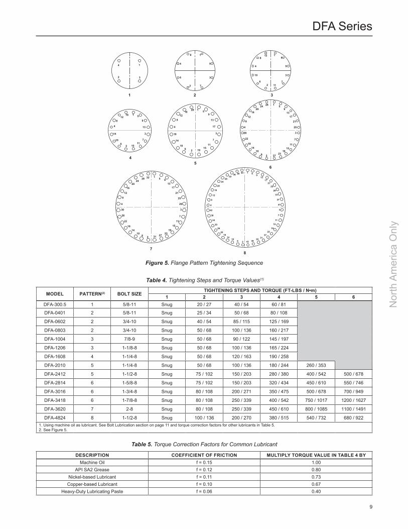
Figure 5. Flange Pattern Tightening Sequence
DESCriPTiOn COEFFiCiEnT OF FriCTiOn MULTiPLY TOrQUE VALUE in TABLE 4 BYMachine Oil f = 0.15 1.00
API SA2 Grease f = 0.12 0.80Nickel-based Lubricant f = 0.11 0.73
Copper-based Lubricant f = 0.10 0.67Heavy-Duty Lubricating Paste f = 0.06 0.40
Table 5. Torque Correction Factors for Common Lubricant
Table 4. Tightening Steps and Torque Values(1)
MODEL PATTErn(2) BOLT SiZETiGHTEninG STEPS AnD TOrQUE (FT-LBS / N•m)
1 2 3 4 5 6DFA-300.5 1 5/8-11 Snug 20 / 27 40 / 54 60 / 81
DFA-0401 2 5/8-11 Snug 25 / 34 50 / 68 80 / 108
DFA-0602 2 3/4-10 Snug 40 / 54 85 / 115 125 / 169
DFA-0803 2 3/4-10 Snug 50 / 68 100 / 136 160 / 217
DFA-1004 3 7/8-9 Snug 50 / 68 90 / 122 145 / 197
DFA-1206 3 1-1/8-8 Snug 50 / 68 100 / 136 165 / 224
DFA-1608 4 1-1/4-8 Snug 50 / 68 120 / 163 190 / 258
DFA-2010 5 1-1/4-8 Snug 50 / 68 100 / 136 180 / 244 260 / 353
DFA-2412 5 1-1/2-8 Snug 75 / 102 150 / 203 280 / 380 400 / 542 500 / 678
DFA-2814 6 1-5/8-8 Snug 75 / 102 150 / 203 320 / 434 450 / 610 550 / 746
DFA-3016 6 1-3/4-8 Snug 80 / 108 200 / 271 350 / 475 500 / 678 700 / 949
DFA-3418 6 1-7/8-8 Snug 80 / 108 250 / 339 400 / 542 750 / 1017 1200 / 1627
DFA-3620 7 2-8 Snug 80 / 108 250 / 339 450 / 610 800 / 1085 1100 / 1491
DFA-4824 8 1-1/2-8 Snug 100 / 136 200 / 270 380 / 515 540 / 732 680 / 9221. Using machine oil as lubricant. See Bolt Lubrication section on page 11 and torque correction factors for other lubricants in Table 5.2. See Figure 5.
1 2
54
7
6
3
1
2 3
4
1
2
3
4 5
6
7
8 1
2
3
4
5
6 7
8
9
10
11
12
1
2
3
4
5
7
8 9
1011
12
13
14
15
16
6
1
3
2
4
5
6
7
8
9
10 11
1213
14
15
16
17
18
19
20
28
28
1
1
5
5
913
17
21
25
913
17
21
25
29
3
3
7
7
11
11
15
15
19
19
23
23
27
31
6
6
2
2
10
10
14
14
18
18
22
22
26
26
30
32
4
4
8
8
12
12
16
16
20
20
24
24
1 59
1317
2125
29
33
37
41
3
7
11
15
1923
273135
39432610
1418
2226
30
34
38
42
4
8
12
16
20
2428
3236 40 44
8
27
9
DFA Series
Nor
th A
mer
ica
Onl
y

DESCriPTiOn COEFFiCiEnT OF FriCTiOn MULTiPLY TOrQUE VALUE in TABLE 6 BYMachine Oil f = 0.15 0.75
API SA2 Grease f = 0.12 0.60Nickel-based Lubricant f = 0.11 0.55
Copper-based Lubricant f = 0.10 0.50Heavy-Duty Lubricating Paste f = 0.06 0.30
Table 8. Torque Correction Factors for Common Lubricants Applied on Flanges
nOMinAL PiPE DiAMETEr nUMBEr OF BOLTS
BOLT DiAMETEr TOrQUEin. mm Ft-lbs N•m
1 4 0.50 12.70 9 12.201-1/4 4 0.50 12.70 13 17.631-1/2 4 0.50 12.70 18 24.40
2 4 0.63 16.00 35 47.452-1/2 4 0.63 16.00 41 55.59
3 4 0.63 16.00 60 81.353-1/2 8 0.63 16.00 34 46.10
4 8 0.63 16.00 43 58.306 8 0.75 19.05 80 108.58 8 0.75 19.05 109 147.810 12 0.88 22.4 101 136.912 12 0.88 22.4 135 183.014 12 1.00 25.0 168 227.816 16 1.00 25.0 159 215.618 16 1.13 28.7 244 330.820 20 1.13 28.7 214 290.224 24 1.25 31.8 253 343.0
Assumptions: Use of SAE grade 5 bolts or studs or stronger. No lubricant. Compressed mineral fiber material or similar.
Notes: If lubricant is used on bolts, apply torque reduction factor listed in Lubricant Table. For best results hardened steel washers should be used on all cast flange bolted connections.
Table 6. Torque Values for Raised Face Connection Flange (Steel Only)
nOMinAL PiPE DiAMETEr nUMBEr OF BOLTS BOLT DiAMETEr TOrQUEin. mm Ft-lbs N•m
1 4 0.50 12.70 14 18.981-1/4 4 0.50 12.70 16 21.691-1/2 4 0.50 12.70 18 24.41
2 4 0.63 16.00 32 43.392-1/2 4 0.63 16.00 43 58.30
3 4 0.63 16.00 47 63.723-1/2 8 0.63 16.00 26 35.25
4 8 0.63 16.00 32 43.396 8 0.75 19.05 49 66.448 8 0.75 19.05 68 92.2010 12 0.88 22.4 69 93.5512 12 0.88 22.4 98 132.914 12 1.00 25.0 138 187.116 16 1.00 25.0 125 169.518 16 1.13 28.7 142 192.520 20 1.13 28.7 135 183.024 24 1.25 31.8 156 211.5
8 API 16 0.50 12.70 20 27.1220 API 16 0.63 16.00 75 101.724 API 20 0.63 16.00 75 101.7
Assumptions: Use of SAE grade 5 bolts or studs or stronger. No lubricant. Elastomer <70 Durometer Shore A.
Notes: Flat faced flanges should never be mated to a raised face flange for installation. If lubricant is used on bolts, apply torque reduction factor listed in Lubricant Table. For best results hardened steel washers should be used on all cast flange bolted connections.
Table 7. Torque Values for Flat Face Connection Flange (Steel or Aluminum)
10
DFA Series
Nor
th A
mer
ica
Onl
y

1. Loosen all outermost nuts on tension studs.2. Tighten the inside jacking nuts on the tension
studs forcing the two conical sections apart. When the two flange faces have separated, remove the tension studs that do not have inside jacking nuts, so that the element assembly can be removed. The inside jacking nuts are installed on all tension studs that facilitate jacking the unit apart. The inside jacking nuts are not installed on tension studs that are taken out, for ease of removal.
3. Thoroughly clean the gasket sealing faces being careful not to damage the sealing surface. For reassembly, lightly grease one side of a new gasket and place it in the machined recess of each interior flange on the two conical sections.
4. Replace the flame element assembly with a new assembly or properly cleaned and inspected existing unit.
5. Loosen the jacking nuts on the tension rods until the flame cell assembly seats onto the gaskets.
6. Replace all tensioning studs and tighten the outer nuts hand tight only. Check to be sure that all the jacking nuts are completely loose and not making contact with the flange face.
7. Torque the bolts in sequence as shown in the Torquing Instruction section.
Torquing instructions
CAUTiOn
Excessive or uneven torque can cause permanent damage to gaskets and housing.
Tools/Supplies Required
• Hand operated conventional torque wrench or power assisted torque wrench appropriate for the specified torque.
• Socket wrenches of the proper size to fit the hex nuts being tightened.
• Molydisulfide based lubricating paste. Molykote® G-n or equivalent.
• Brush suitable for applying lubricant to the studs.• Wiping rags necessary for the clean up of excessive lubricant.
Molykote® G-n is a mark owned by Dow Corning Corporation.
Procedure
1. Use studs and nuts that are free of visible contamination and corrosion.
2. Apply lubricant to the threads of the stud protruding outboard of the interior flanges and to the face of the hex nuts which will contact the flange.
3. Assemble the nuts to the studs such that the amount of thread extending outboard beyond the nut is approximately equal on both ends.
4. Tighten the nuts to the torque values shown in Table 4 following the designated sequence, repeating the sequence as shown. Flange pattern tightening sequences are shown in Figure 5.
Bolt LubricationLubrication affects required torque of clean fasteners in good condition more than any other factor. In fact, 90% of applied torque goes to overcome friction while only 10% actually stretches the bolt. Table 4 assumes that only machine oil is used as a lubricant. Table 5 shows a list of several common lubricants and their effect on torque required to stretch bolts to 50% of their yield strength. Most are available from local bearing distributors.
recommended Spare PartsFor installations that require frequent maintenance and minimum downtime, it is recommended that the user purchase a spare element assembly and several spare element gaskets. The spare element assembly can be installed immediately and the dirty assembly can then be cleaned and stored as a spare for the next maintenance interval.
noteElement gaskets must be replaced each time the cell assembly is loosened and removed to ensure a gas tight seal.
Parts OrderingWhen corresponding with your local Sales Office about this equipment, always reference the equipment serial number stamped on the nameplate.
11
DFA Series
Nor
th A
mer
ica
Onl
y

DFA Series
Facebook.com/EmersonAutomationSolutions
LinkedIn.com/company/emerson-automation-solutions
Twitter.com/emr_automation
Enardo.com
D103809X012 © 2015, 2019 Emerson Process Management Regulator Technologies, Inc. All rights reserved. 01/19. The Emerson logo is a trademark and service mark of Emerson Electric Co. All other marks are the property of their prospective owners. Enardo™ is a mark owned by Regulator Technologies Tulsa, LLC, a business of Emerson Automation Solutions.
The contents of this publication are presented for informational purposes only, and while every effort has been made to ensure their accuracy, they are not to be construed as warranties or guarantees, express or implied, regarding the products or services described herein or their use or applicability. We reserve the right to modify or improve the designs or specifications of such products at any time without notice.
Emerson Process Management Regulator Technologies Tulsa, LLC does not assume responsibility for the selection, use or maintenance of any product. Responsibility for proper selection, use and maintenance of any Emerson Process Management Regulator Technologies Tulsa, LLC product remains solely with the purchaser.
Nor
th A
mer
ica
Onl
y
Emerson Automation Solutions
Americas McKinney, Texas 75070 USA T +1 800 558 5853
+1 972 548 3574Tulsa, OK 74146 USA T +1 918 662 6161
Europe Bologna 40013, Italy T +39 051 419 0611
Asia Pacific Singapore 128461, Singapore T +65 6777 8211
Middle East and Africa Dubai, United Arab Emirates T +971 4 811 8100