
Manual Yaskawa_servo_drive.pdf
330
MANUAL NO. SIEP S80000 0 60E SGDV SERVOP ACK SGMJV/SGMA V/SGMPS/SGMGV/SGMSV /SGMCS Servomotors Rotational Motor Command Option Attachable T ype -V Series AC Servo Drives USER’S MANUAL Design and Maintenance Outline Wiring and Connection Operation Adjustments Utility Functions (Fn) Monitor Modes (Un) Fully-closed Loop Control Troubleshooting Appendix 1 2 3 4 5 6 7 8 9 10 Panel Display and Operation of Digital Operator
-
Upload
valeriocbr -
Category
Documents
-
view
80 -
download
0
Transcript of Manual Yaskawa_servo_drive.pdf

7/17/2019 Manual Yaskawa_servo_drive.pdf
http://slidepdf.com/reader/full/manual-yaskawaservodrivepdf 1/328
MANUAL NO. SIEP S800000 60E
SGDV SERVOPACKSGMJV/SGMAV/SGMPS/SGMGV/SGMSV/SGMCS Servomotors
Rotational MotorCommand Option Attachable Type
-V SeriesAC Servo Drives
USER’S MANUAL Design and Maintenance
Outline
Wiring and Connection
Operation
Adjustments
Utility Functions (Fn)
Monitor Modes (Un)
Fully-closed Loop Control
Troubleshooting
Appendix
1
2
3
4
5
6
7
8
9
10
Panel Display andOperation of Digital Operator

7/17/2019 Manual Yaskawa_servo_drive.pdf
http://slidepdf.com/reader/full/manual-yaskawaservodrivepdf 2/328
Copyright © 2009 YASKAWA ELECTRIC CORPORATION
All rights reserved. No part of this publication may be reproduced, stored in a retrieval system,or transmitted, in any form, or by any means, mechanical, electronic, photocopying, recording,
or otherwise, without the prior written permission of Yaskawa. No patent liability is assumedwith respect to the use of the information contained herein. Moreover, because Yaskawa is con-stantly striving to improve its high-quality products, the information contained in this manual issubject to change without notice. Every precaution has been taken in the preparation of thismanual. Nevertheless, Yaskawa assumes no responsibility for errors or omissions. Neither isany liability assumed for damages resulting from the use of the information contained in this
publication.
7/17/2019 Manual Yaskawa_servo_drive.pdf
http://slidepdf.com/reader/full/manual-yaskawaservodrivepdf 3/328iii
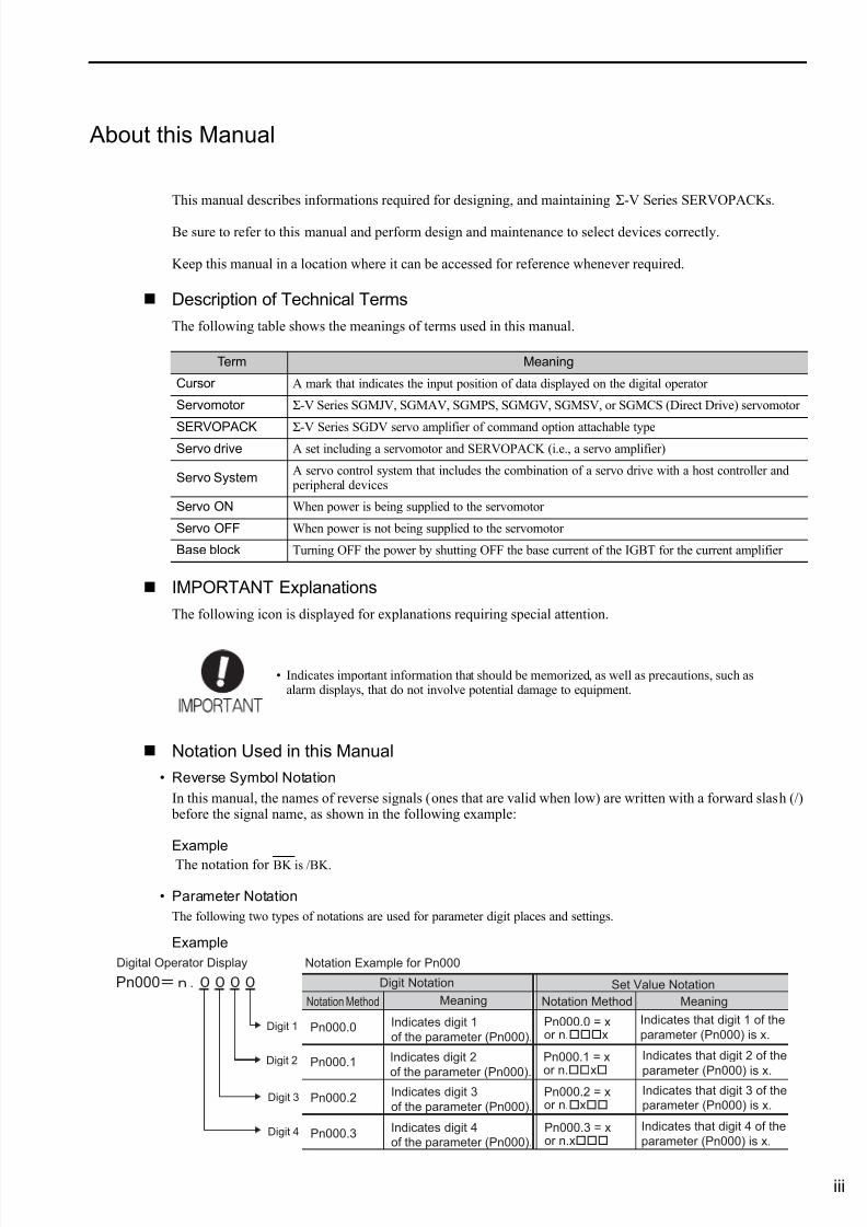
About this Manual
This manual describes informations required for designing, and maintaining Σ-V Series SERVOPACKs.
Be sure to refer to this manual and perform design and maintenance to select devices correctly.
Keep this manual in a location where it can be accessed for reference whenever required.
Description of Technical Terms
The following table shows the meanings of terms used in this manual.
IMPORTANT Explanations
The following icon is displayed for explanations requiring special attention.
Notation Used in this Manual
• Reverse Symbol Notation
In this manual, the names of reverse signals (ones that are valid when low) are written with a forward slash (/) before the signal name, as shown in the following example:
Example
The notation for BK is /BK.
• Parameter Notation
The following two types of notations are used for parameter digit places and settings.
Example
Term Meaning
Cursor A mark that indicates the input position of data displayed on the digital operator
Servomotor Σ-V Series SGMJV, SGMAV, SGMPS, SGMGV, SGMSV, or SGMCS (Direct Drive) servomotor
SERVOPACK Σ-V Series SGDV servo amplifier of command option attachable typeServo drive A set including a servomotor and SERVOPACK (i.e., a servo amplifier)
Servo SystemA servo control system that includes the combination of a servo drive with a host controller and peripheral devices
Servo ON When power is being supplied to the servomotor
Servo OFF When power is not being supplied to the servomotor
Base block Turning OFF the power by shutting OFF the base current of the IGBT for the current amplifier
• Indicates important information that should be memorized, as well as precautions, such asalarm displays, that do not involve potential damage to equipment.
Digital Operator Display
Pn000.0
Pn000.1
Pn000.2
Pn000.3
Pn000
Digit 1
Digit 2
Digit 3
Digit 4
Notation Example for Pn000
Digit Notation Set Value Notation
Notation Method Meaning Notation Method Meaning
Indicates digit 1
of the parameter (Pn000).
Indicates digit 2
of the parameter (Pn000).Indicates digit 3
of the parameter (Pn000).
Indicates digit 4
of the parameter (Pn000).
Indicates that digit 1 of the
parameter (Pn000) is x.
Indicates that digit 2 of the
parameter (Pn000) is x.Indicates that digit 3 of the
parameter (Pn000) is x.
Indicates that digit 4 of the
parameter (Pn000) is x.
Pn000.0 = xor n.x
Pn000.1 = x
or n.
x
Pn000.2 = xor n.x
Pn000.3 = xor n.x
7/17/2019 Manual Yaskawa_servo_drive.pdf
http://slidepdf.com/reader/full/manual-yaskawaservodrivepdf 4/328
v
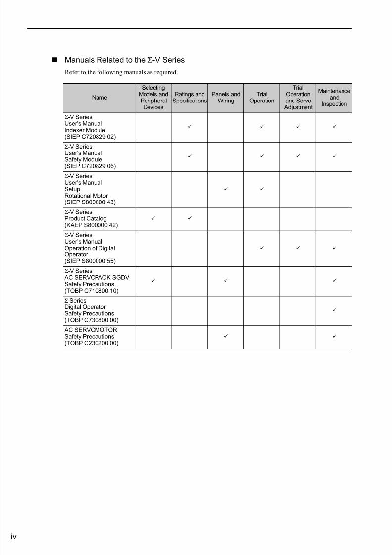
Manuals Related to the Σ-V Series
Refer to the following manuals as required.
Name
Selecting
Models andPeripheralDevices
Ratings andSpecifications Panels andWiring TrialOperation
Trial
Operationand Servo Adjustment
Maintenance
andInspection
Σ-V SeriesUser's ManualIndexer Module(SIEP C720829 02)
Σ-V SeriesUser's ManualSafety Module(SIEP C720829 06)
Σ-V SeriesUser's ManualSetup
Rotational Motor(SIEP S800000 43)
Σ-V SeriesProduct Catalog(KAEP S800000 42)
Σ-V SeriesUser’s ManualOperation of DigitalOperator (SIEP S800000 55)
Σ-V Series AC SERVOPACK SGDVSafety Precautions
(TOBP C710800 10)
Σ SeriesDigital Operator Safety Precautions(TOBP C730800 00)
AC SERVOMOTORSafety Precautions(TOBP C230200 00)
7/17/2019 Manual Yaskawa_servo_drive.pdf
http://slidepdf.com/reader/full/manual-yaskawaservodrivepdf 5/328v
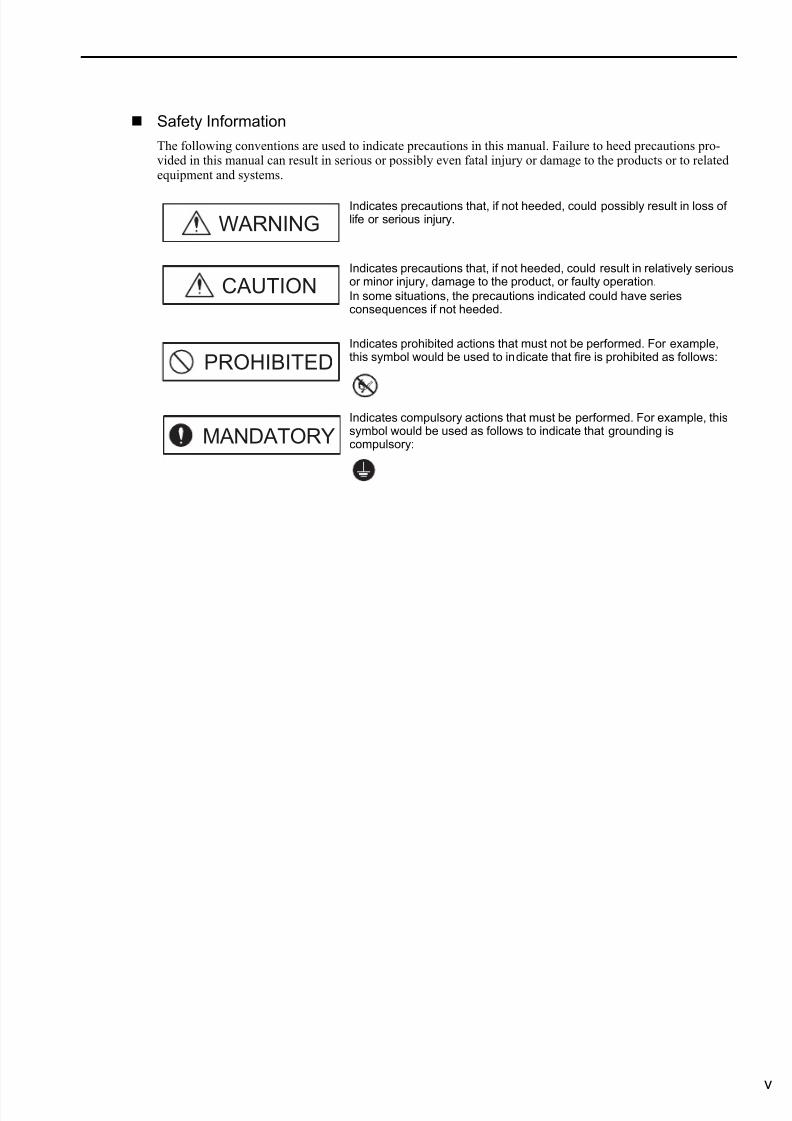
Safety Information
The following conventions are used to indicate precautions in this manual. Failure to heed precautions pro-vided in this manual can result in serious or possibly even fatal injury or damage to the products or to relatedequipment and systems.
Indicates precautions that, if not heeded, could possibly result in loss oflife or serious injury.
Indicates precautions that, if not heeded, could result in relatively seriousor minor injury, damage to the product, or faulty operation.
In some situations, the precautions indicated could have seriesconsequences if not heeded.
Indicates prohibited actions that must not be performed. For example,this symbol would be used to indicate that fire is prohibited as follows:
Indicates compulsory actions that must be performed. For example, thissymbol would be used as follows to indicate that grounding iscompulsory:
WARNING
CAUTION
PROHIBITED
MANDATORY
7/17/2019 Manual Yaskawa_servo_drive.pdf
http://slidepdf.com/reader/full/manual-yaskawaservodrivepdf 6/328
vi
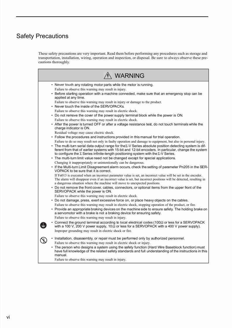
Safety Precautions
These safety precautions are very important. Read them before performing any procedures such as storage and
transportation, installation, wiring, operation and inspection, or disposal. Be sure to always observe these pre-cautions thoroughly.
WARNING
• Never touch any rotating motor parts while the motor is running.
Failure to observe this warning may result in injury.
• Before starting operation with a machine connected, make sure that an emergency stop can beapplied at any time.
Failure to observe this warning may result in injury or damage to the product.
• Never touch the inside of the SERVOPACKs.
Failure to observe this warning may result in electric shock.
• Do not remove the cover of the power supply terminal block while the power is ON.Failure to observe this warning may result in electric shock.
• After the power is turned OFF or after a voltage resistance test, do not touch terminals while thecharge indicator is ON.
Residual voltage may cause electric shock.
• Follow the procedures and instructions provided in this manual for trial operation.
Failure to do so may result not only in faulty operation and damage to equipment, but also in personal injury.
• The multi-turn serial data output range for the Σ-V Series absolute position detecting system is dif-ferent from that of earlier systems with 15-bit and 12-bit encoders. In particular, change the systemto configure the Σ Series infinite-length positioning system with the Σ-V Series.
• The multi-turn limit value need not be changed except for special applications.
Changing it inappropriately or unintentionally can be dangerous.
• If the Multi-turn Limit Disagreement alarm occurs, check the setting of parameter Pn205 in the SER-
VOPACK to be sure that it is correct.If Fn013 is executed when an incorrect parameter value is set, an incorrect value will be set in the encoder.The alarm will disappear even if an incorrect value is set, but incorrect positions will be detected, resulting ina dangerous situation where the machine will move to unexpected positions.
• Do not remove the front cover, cables, connectors, or optional items from the upper front of theSERVOPACK while the power is ON.
Failure to observe this warning may result in electric shock.
• Do not damage, press, exert excessive force on, or place heavy objects on the cables.
Failure to observe this warning may result in electric shock, stopping operation of the product, or fire.
• Provide an appropriate braking devices on the machine side to ensure safety. The holding brake ona servomotor with a brake is not a braking device for ensuring safety.
Failure to observe this warning may result in injury.
• Connect the ground terminal according to local electrical codes (100 Ω or less for a SERVOPACKwith a 100 V, 200 V power supply, 10 Ω or less for a SERVOPACK with a 400 V power supply).
Improper grounding may result in electric shock or fire.
• Installation, disassembly, or repair must be performed only by authorized personnel.
Failure to observe this warning may result in electric shock or injury.
• The person who designs a system using the safety function (Hard Wire Baseblock function) musthave full knowledge of the related safety standards and full understanding of the instructions in thismanual.
Failure to observe this warning may result in injury.
7/17/2019 Manual Yaskawa_servo_drive.pdf
http://slidepdf.com/reader/full/manual-yaskawaservodrivepdf 7/328vii
Storage and Transportation
Installation
CAUTION
• Do not store or install the product in the following locations.Failure to observe this caution may result in fire, electric shock, or damage to the product.
• Locations subject to direct sunlight
• Locations subject to ambient operating temperatures outside the range specified in the storage/installationtemperature conditions
• Locations subject to humidity outside the range specified in the storage/installation humidity conditions
• Locations subject to condensation as the result of extreme changes in temperature
• Locations subject to corrosive or flammable gases
• Locations subject to dust, salts, or iron dust
• Locations subject to exposure to water, oil, or chemicals
• Locations subject to shock or vibration
• Do not hold the product by the cables, motor shaft or detector while transporting it.
Failure to observe this caution may result in injury or malfunction.
• Do not place any load exceeding the limit specified on the packing box.Failure to observe this caution may result in injury or malfunction.
• If disinfectants or insecticides must be used to treat packing materials such as wooden frames, pal-lets, or plywood, the packing materials must be treated before the product is packaged, and meth-ods other than fumigation must be used.Example: Heat treatment, where materials are kiln-dried to a core temperature of 56°C for 30
minutes or more.
If the electronic products, which include stand-alone products and products installed in machines, are packedwith fumigated wooden materials, the electrical components may be greatly damaged by the gases or fumesresulting from the fumigation process. In particular, disinfectants containing halogen, which includes chlo-rine, fluorine, bromine, or iodine can contribute to the erosion of the capacitors.
CAUTION
• Never use the product in an environment subject to water, corrosive gases, inflammable gases, orcombustibles.
Failure to observe this caution may result in electric shock or fire.
• Do not step on or place a heavy object on the product.
Failure to observe this caution may result in injury.
• Do not cover the inlet or outlet ports and prevent any foreign objects from entering the product.
Failure to observe this caution may cause internal elements to deteriorate resulting in malfunction or fire.
• Be sure to install the product in the correct direction.
Failure to observe this caution may result in malfunction.
• Provide the specified clearances between the SERVOPACK and the control panel or with other
devices.Failure to observe this caution may result in fire or malfunction.
• Do not apply any strong impact.
Failure to observe this caution may result in malfunction.
7/17/2019 Manual Yaskawa_servo_drive.pdf
http://slidepdf.com/reader/full/manual-yaskawaservodrivepdf 8/328
viii
Wiring
CAUTION
• Be sure to wire correctly and securely.Failure to observe this caution may result in motor overrun, injury, or malfunction.
• Do not connect a commercial power supply to the U, V, or W terminals for the servomotor connec-tion.
Failure to observe this caution may result in injury or fire.
• Securely connect the main circuit power supply terminal screws, control power supply terminalscrews, and servomotor connection terminal screws.
Failure to observe this caution may result in fire.
• Do not bundle or run the main circuit cables together with the input/output signal cables or theencoder cables in the same duct. Keep them separated by at least 30 cm.
Failure to do so may result in malfunction.
• Use shielded twisted-pair wires or multi-core shielded twisted-pair wires for input/output signalcables and the encoder cables.
• I/O signal cables must be no longer than 3 m, encoder cables must be no longer than 50 m, andcontrol power supply cables for the SERVOPACK with a 400 V power supply (+24 V, 0 V) must beno longer than 10 m.
• Do not touch the power terminals while the charge indicator is ON after turning power OFF becausehigh voltage may still remain in the SERVOPACK.
Make sure the charge indicator is off first before starting an inspection.
• Observe the following precautions when wiring main circuit terminal blocks of the SERVOPACK.
• Remove the detachable main circuit terminal blocks from the SERVOPACK prior to wiring.
• Insert only one main power line per opening in the main circuit terminals.
• Make sure that no part of the core wire comes into contact with (i.e., short-circuit) adjacent wires.
• Install a battery at either the host controller or the SERVOPACK, but not both.
It is dangerous to install batteries at both ends simultaneously, because that sets up a loop circuit between the batteries.
• Always use the specified power supply voltage.
An incorrect voltage may result in fire or malfunction.• Take appropriate measures to ensure that the input power supply is supplied within the specified
voltage fluctuation range. Be particularly careful in places where the power supply is unstable.
An incorrect power supply may result in damage to the product.
• Install external breakers or other safety devices against short-circuiting in external wiring.
Failure to observe this caution may result in fire.
• Take appropriate and sufficient countermeasures for each form of potential interference wheninstalling systems in the following locations.
• Locations subject to static electricity or other forms of noise
• Locations subject to strong electromagnetic fields and magnetic fields
• Locations subject to possible exposure to radioactivity
• Locations close to power supplies
Failure to observe this caution may result in damage to the product.
• Do not reverse the polarity of the battery when connecting it.Failure to observe this caution may damage the battery, the SERVOPACK, the servomotor, or cause an explo-sion.
• Wiring or inspection must be performed by a technical expert.
• Use a 24-VDC power supply with double insulation or reinforced insulation.
7/17/2019 Manual Yaskawa_servo_drive.pdf
http://slidepdf.com/reader/full/manual-yaskawaservodrivepdf 9/328ix
Operation
Maintenance and Inspection
CAUTION
• Always use the servomotor and SERVOPACK in one of the specified combinations.Failure to observe this caution so may result in fire or malfunction.
• Conduct trial operation on the servomotor alone with the motor shaft disconnected from themachine to avoid accidents.
Failure to observe this caution may result in injury.
• During trial operation, confirm that the holding brake works correctly. Furthermore, secure systemsafety against problems such as signal line disconnection.
Failure to observe this caution may result in damage to the equipment or injury.
• Before starting operation with a machine connected, change the settings to match the parametersof the machine.
Starting operation without matching the proper settings may cause the machine to run out of control or mal-function.
• Do not frequently turn power ON and OFF.
Since the SERVOPACK has a capacitor in the power supply, a high charging current flows when power is
turned ON. Frequently turning power ON and OFF causes main power devices like capacitors and fuses todeteriorate, resulting in unexpected problems.
• When using JOG operations (Fn002), search operations (Fn003), or EasyFFT operations (Fn206),the dynamic brake function does not work for reverse overtravel or forward overtravel. Take neces-sary precautions.
• When using the servomotor for a vertical axis, install safety devices to prevent workpieces from fall-ing due to alarms or overtravels. Set the servomotor so that it will stop in the zero clamp state whenovertravel occurs.
Failure to observe this caution may cause workpieces to fall due to overtravel.
• When not using turning-less function, set to the correct moment of inertia ratio (Pn103).
Setting to an incorrect moment of inertia ratio may cause machine vibration.
• Do not touch the SERVOPACK heatsinks, regenerative resistor, or servomotor while power is ON orsoon after the power is turned OFF.
Failure to observe this caution may result in burns due to high temperatures.
• Do not make any extreme adjustments or setting changes of parameters.
Failure to observe this caution may result in injury or damage to the product due to unstable operation.
• When an alarm occurs, remove the cause, reset the alarm after confirming safety, and then resumeoperation.
Failure to observe this caution may result in damage to the product, fire, or injury.
• Do not use the brake of the servomotor for braking.
Failure to observe this caution may result in malfunction.
• An alarm or warning may be generated if communications are executed with the host controller dur-ing operation using SigmaWin+ or the digital operator.
If an alarm or warning is generated, the process currently being executed may be aborted and the system maystop.
CAUTION
• Do not disassemble the SERVOPACK.
Failure to observe this caution may result in electric shock or injury.
• Do not change wiring while the power is ON.
Failure to observe this caution may result in electric shock or injury.
• When replacing the SERVOPACK, resume operation only after copying the previous SERVOPACKparameters to the new SERVOPACK.
Failure to observe this caution may result in damage to the product.

7/17/2019 Manual Yaskawa_servo_drive.pdf
http://slidepdf.com/reader/full/manual-yaskawaservodrivepdf 10/328
x
Disposal
General Precautions
CAUTION
• When disposing of the products, treat them as ordinary industrial waste.
Observe the following general precautionsto ensure safe application.
• The products shown in illustrations in this manual are sometimes shown without covers or protective guards.Always replace the cover or protective guard as specified first, and then operate the products in accordance withthe manual.
• The drawings presented in this manual are typical examples and may not match the product you received.
• If the manual must be ordered due to loss or damage, inform your nearest Yaskawa representative or one of theoffices listed on the back of this manual.
7/17/2019 Manual Yaskawa_servo_drive.pdf
http://slidepdf.com/reader/full/manual-yaskawaservodrivepdf 11/328xi
Warranty
(1) Details of Warranty
Warranty Period
The warranty period for a product that was purchased (hereinafter called “delivered product”) is one year fromthe time of delivery to the location specified by the customer or 18 months from the time of shipment from theYaskawa factory, whichever is sooner.
Warranty Scope
Yaskawa shall replace or repair a defective product free of charge if a defect attributable to Yaskawa occursduring the warranty period above. This warranty does not cover defects caused by the delivered product reach-ing the end of its service life and replacement of parts that require replacement or that have a limited servicelife.
This warranty does not cover failures that result from any of the following causes.
1. Improper handling, abuse, or use in unsuitable conditions or in environments not described in product cata-logs or manuals, or in any separately agreed-upon specifications
2. Causes not attributable to the delivered product itself
3. Modifications or repairs not performed by Yaskawa
4. Abuse of the delivered product in a manner in which it was not originally intended
5. Causes that were not foreseeable with the scientific and technological understanding at the time of ship-ment from Yaskawa
6. Events for which Yaskawa is not responsible, such as natural or human-made disasters
(2) Limitations of Liability1. Yaskawa shall in no event be responsible for any damage or loss of opportunity to the customer that arises
due to failure of the delivered product.
2. Yaskawa shall not be responsible for any programs (including parameter settings) or the results of program
execution of the programs provided by the user or by a third party for use with programmable Yaskawa products.
3. The information described in product catalogs or manuals is provided for the purpose of the customer pur-chasing the appropriate product for the intended application. The use thereof does not guarantee that thereare no infringements of intellectual property rights or other proprietary rights of Yaskawa or third parties,nor does it construe a license.
4. Yaskawa shall not be responsible for any damage arising from infringements of intellectual property rightsor other proprietary rights of third parties as a result of using the information described in catalogs or man-uals.

7/17/2019 Manual Yaskawa_servo_drive.pdf
http://slidepdf.com/reader/full/manual-yaskawaservodrivepdf 12/328
xii
(3) Suitability for Use1. It is the customer’s responsibility to confirm conformity with any standards, codes, or regulations that
apply if the Yaskawa product is used in combination with any other products.
2. The customer must confirm that the Yaskawa product is suitable for the systems, machines, and equipment
used by the customer.3. Consult with Yaskawa to determine whether use in the following applications is acceptable. If use in the
application is acceptable, use the product with extra allowance in ratings and specifications, and providesafety measures to minimize hazards in the event of failure.
• Outdoor use, use involving potential chemical contamination or electrical interference, or use in condi-tions or environments not described in product catalogs or manuals
• Nuclear energy control systems, combustion systems, railroad systems, aviation systems, vehicle sys-tems, medical equipment, amusement machines, and installations subject to separate industry or gov-ernment regulations
• Systems, machines, and equipment that may present a risk to life or property
• Systems that require a high degree of reliability, such as systems that supply gas, water, or electricity, orsystems that operate continuously 24 hours a day
• Other systems that require a similar high degree of safety
4. Never use the product for an application involving serious risk to life or property without first ensuring thatthe system is designed to secure the required level of safety with risk warnings and redundancy, and that theYaskawa product is properly rated and installed.
5. The circuit examples and other application examples described in product catalogs and manuals are for ref-erence. Check the functionality and safety of the actual devices and equipment to be used before using the
product.
6. Read and understand all use prohibitions and precautions, and operate the Yaskawa product correctly to prevent accidental harm to third parties.
(4) Specifications ChangeThe names, specifications, appearance, and accessories of products in product catalogs and manuals may bechanged at any time based on improvements and other reasons. The next editions of the revised catalogs or
manuals will be published with updated code numbers. Consult with your Yaskawa representative to confirmthe actual specifications before purchasing a product.

7/17/2019 Manual Yaskawa_servo_drive.pdf
http://slidepdf.com/reader/full/manual-yaskawaservodrivepdf 13/328xiii
Applicable Standards
North American Safety Standards (UL/CSA)
∗ Underwriters Laboratories Inc.
European Standards
Note: Because SERVOPACKs and servomotors are built into machines, certification is required after installation in thefinal product.
Model UL∗ Standards(UL File No.)
SERVOPACK • SGDV UL508C (E147823)
Servomotor
• SGMJV
• SGMAV• SGMPS
• SGMGV
• SGMSV
UL1004 (E165827)
ModelLow Voltage
DirectiveEMC Directive Safety
StandardsEMI EMS
SERVOPACK • SGDVEN50178
EN61800-5-1
EN55011group 1 class A,
EN61800-3
EN61800-3EN61000-6-2
EN954-1IEC61508-1 to 4
Servomotor
• SGMJV
• SGMAV
• SGMPS
• SGMGV
• SGMSV
IEC60034-1IEC60034-5IEC60034-8IEC60034-9
EN55011group 1 class A,
EN61800-3
EN61800-3EN61000-6-2
–
7/17/2019 Manual Yaskawa_servo_drive.pdf
http://slidepdf.com/reader/full/manual-yaskawaservodrivepdf 14/328
xiv
Contents
About this Manual . . . . . . . . . . . . . . . . . . . . . . . . . . . . . . . . . . . . . . . . . . . . . . . . . . . . . . . . iiiSafety Precautions. . . . . . . . . . . . . . . . . . . . . . . . . . . . . . . . . . . . . . . . . . . . . . . . . . . . . . . . vi
Warranty. . . . . . . . . . . . . . . . . . . . . . . . . . . . . . . . . . . . . . . . . . . . . . . . . . . . . . . . . . . . . . . . xi
Applicable Standards . . . . . . . . . . . . . . . . . . . . . . . . . . . . . . . . . . . . . . . . . . . . . . . . . . . . . xiii
Chapter 1 Outline . . . . . . . . . . . . . . . . . . . . . . . . . . . . . . . . . . . . . . . . . . . 1-1
1.1 Σ-V Series SERVOPACKs . . . . . . . . . . . . . . . . . . . . . . . . . . . . . . . . . . . . . . . 1-2
1.2 SERVOPACKs . . . . . . . . . . . . . . . . . . . . . . . . . . . . . . . . . . . . . . . . . . . . . . . . 1-2
1.3 Part Names . . . . . . . . . . . . . . . . . . . . . . . . . . . . . . . . . . . . . . . . . . . . . . . . . . 1-2
1.4 SERVOPACK Ratings and Specifications . . . . . . . . . . . . . . . . . . . . . . . . . . . 1-31.4.1 Ratings . . . . . . . . . . . . . . . . . . . . . . . . . . . . . . . . . . . . . . . . . . . . . . . . . . . . . . . . . . . . . . . .1-3
1.4.2 Basic Specifications . . . . . . . . . . . . . . . . . . . . . . . . . . . . . . . . . . . . . . . . . . . . . . . . . . . . . .1-4
1.5 SERVOPACK Internal Block Diagrams . . . . . . . . . . . . . . . . . . . . . . . . . . . . . 1-61.5.1 Single-phase 100-V, SGDV-R70FE1A, -R90FE1A, -2R1FE1A Models. . . . . . . . . . . . . . . 1-6
1.5.2 Single-phase 100-V, SGDV-2R8FE1A Model . . . . . . . . . . . . . . . . . . . . . . . . . . . . . . . . . .1-6
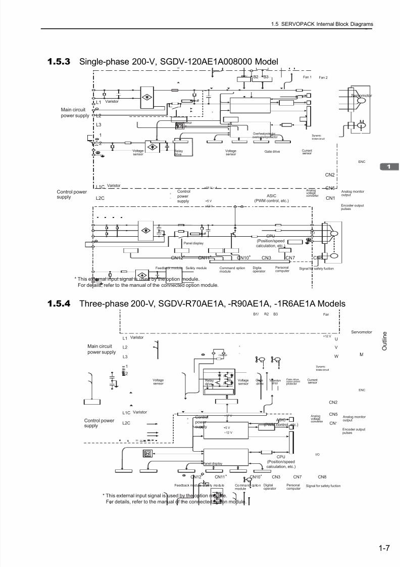
1.5.3 Single-phase 200-V, SGDV-120AE1A008000 Model. . . . . . . . . . . . . . . . . . . . . . . . . . . . .1-7
1.5.4 Three-phase 200-V, SGDV-R70AE1A, -R90AE1A, -1R6AE1A Models. . . . . . . . . . . . . . . 1-7
1.5.5 Three-phase 200-V, SGDV-2R8AE1A Model. . . . . . . . . . . . . . . . . . . . . . . . . . . . . . . . . . .1-8
1.5.6 Three-phase 200-V, SGDV-3R8AE1A, -5R5AE1A, -7R6AE1A Models. . . . . . . . . . . . . . . 1-8
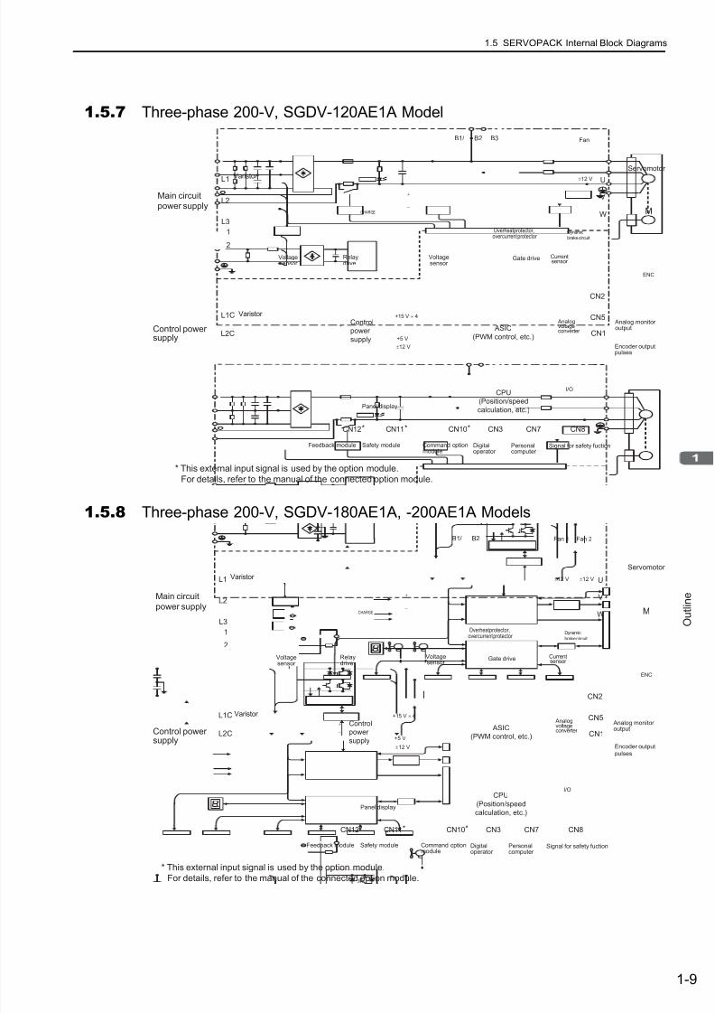
1.5.7 Three-phase 200-V, SGDV-120AE1A Model . . . . . . . . . . . . . . . . . . . . . . . . . . . . . . . . . . .1-9
1.5.8 Three-phase 200-V, SGDV-180AE1A, -200AE1A Models . . . . . . . . . . . . . . . . . . . . . . . . .1-9
1.5.9 Three-phase 200-V, SGDV-330AE1A Model . . . . . . . . . . . . . . . . . . . . . . . . . . . . . . . . . .1-10
1.5.10 Three-phase 200-V, SGDV-470AE1A, -550AE1A Models . . . . . . . . . . . . . . . . . . . . . . .1-10
1.5.11 Three-phase 200-V, SGDV-590AE1A, -780AE1A Models . . . . . . . . . . . . . . . . . . . . . . . 1-11
1.5.12 Three-phase 400-V, SGDV-1R9DE1A, -3R5DE1A, -5R4DE1A Models . . . . . . . . . . . . 1-111.5.13 Three-phase 400-V, SGDV-8R4DE1A, -120DE1A Models . . . . . . . . . . . . . . . . . . . . . .1-12
1.5.14 Three-phase 400-V, SGDV-170DE1A Model . . . . . . . . . . . . . . . . . . . . . . . . . . . . . . . . .1-12
1.5.15 Three-phase 400-V, SGDV-210DE1A, -260DE1A Models. . . . . . . . . . . . . . . . . . . . . . . 1-13
1.5.16 Three-phase 400-V, SGDV-280DE1A, -370DE1A Models. . . . . . . . . . . . . . . . . . . . . . . 1-13
1.6 Examples of Servo System Configurations . . . . . . . . . . . . . . . . . . . . . . . . .1-141.6.1 Connecting to SGDV-FE1A SERVOPACK . . . . . . . . . . . . . . . . . . . . . . . . . . . . . . .1-14
1.6.2 Connecting to SGDV- AE1A SERVOPACK. . . . . . . . . . . . . . . . . . . . . . . . . . . . . . . 1-15
1.6.3 Connecting to SGDV-DE1A SERVOPACK. . . . . . . . . . . . . . . . . . . . . . . . . . . . . . . 1-17
1.7 SERVOPACK Model Designation. . . . . . . . . . . . . . . . . . . . . . . . . . . . . . . . . 1-18
1.8 Inspection and Maintenance . . . . . . . . . . . . . . . . . . . . . . . . . . . . . . . . . . . .1-19
Chapter 2 Panel Display and Operation of Digital Operator . . . . . . . . . . . 2-1
2.1 Panel Display . . . . . . . . . . . . . . . . . . . . . . . . . . . . . . . . . . . . . . . . . . . . . . . . . 2-22.1.1 Status Display . . . . . . . . . . . . . . . . . . . . . . . . . . . . . . . . . . . . . . . . . . . . . . . . . . . . . . . . . .2-2
2.1.2 Alarm and Warning Display . . . . . . . . . . . . . . . . . . . . . . . . . . . . . . . . . . . . . . . . . . . . . . . .2-2
2.1.3 Hard Wire Base Block Display . . . . . . . . . . . . . . . . . . . . . . . . . . . . . . . . . . . . . . . . . . . . . . 2-2
2.1.4 Displays during Overtravel . . . . . . . . . . . . . . . . . . . . . . . . . . . . . . . . . . . . . . . . . . . . . . . . .2-2
2.2 Utility Function Mode (Fn). . . . . . . . . . . . . . . . . . . . . . . . . . . . . . . . . . . 2-3
2.3 Parameter (Pn) Operation . . . . . . . . . . . . . . . . . . . . . . . . . . . . . . . . . . 2-42.3.1 Parameter Classifications . . . . . . . . . . . . . . . . . . . . . . . . . . . . . . . . . . . . . . . . . . . . . . . . . 2-4
2.3.2 Parameter Notation . . . . . . . . . . . . . . . . . . . . . . . . . . . . . . . . . . . . . . . . . . . . . . . . . . . . . . 2-4
2.3.3 Parameter Setting Methods . . . . . . . . . . . . . . . . . . . . . . . . . . . . . . . . . . . . . . . . . . . . . . . . 2-5
2.4 Monitor Mode (Un) . . . . . . . . . . . . . . . . . . . . . . . . . . . . . . . . . . . . . . . . 2-7
7/17/2019 Manual Yaskawa_servo_drive.pdf
http://slidepdf.com/reader/full/manual-yaskawaservodrivepdf 15/328xv
Chapter 3 Wiring and Connection . . . . . . . . . . . . . . . . . . . . . . . . . . . . . . . 3-1
3.1 Main Circuit Wiring. . . . . . . . . . . . . . . . . . . . . . . . . . . . . . . . . . . . . . . . . . . . . 3-23.1.1 Main Circuit Terminals . . . . . . . . . . . . . . . . . . . . . . . . . . . . . . . . . . . . . . . . . . . . . . . . . . . .3-2
3.1.2 Using a Standard Power Supply Input(Single-phase 100-V, Three-phase 200-V, or Three-phase 400-V) . . . . . . . . . . . . . . . . . . 3-3
3.1.3 Using the SERVOPACK with Single-phase, 200-V Power Input . . . . . . . . . . . . . . . . . . . 3-12
3.1.4 Using the SERVOPACK with a DC Power Input . . . . . . . . . . . . . . . . . . . . . . . . . . . . . . .3-15
3.1.5 Using More Than One SERVOPACK. . . . . . . . . . . . . . . . . . . . . . . . . . . . . . . . . . . . . . . .3-17
3.1.6 General Precautions for Wiring . . . . . . . . . . . . . . . . . . . . . . . . . . . . . . . . . . . . . . . . . . . .3-18
3.2 I/O Signal Connections . . . . . . . . . . . . . . . . . . . . . . . . . . . . . . . . . . . . . . . . 3-193.2.1 I/O Signal (CN1) Names and Functions. . . . . . . . . . . . . . . . . . . . . . . . . . . . . . . . . . . . . .3-19
3.2.2 Safety Function Signal (CN8) Names and Functions. . . . . . . . . . . . . . . . . . . . . . . . . . . .3-20
3.2.3 Example of I/O Signal Connections . . . . . . . . . . . . . . . . . . . . . . . . . . . . . . . . . . . . . . . . . 3-21
3.3 I/O Signal Allocations. . . . . . . . . . . . . . . . . . . . . . . . . . . . . . . . . . . . . . . . . . 3-223.3.1 Input Signal Allocations . . . . . . . . . . . . . . . . . . . . . . . . . . . . . . . . . . . . . . . . . . . . . . . . . .3-22
3.3.2 Output Signal Allocation. . . . . . . . . . . . . . . . . . . . . . . . . . . . . . . . . . . . . . . . . . . . . . . . . .3-24
3.4 Connection to Host Controller . . . . . . . . . . . . . . . . . . . . . . . . . . . . . . . . . . . 3-253.4.1 Sequence Input Circuits. . . . . . . . . . . . . . . . . . . . . . . . . . . . . . . . . . . . . . . . . . . . . . . . . .3-25
3.4.2 Sequence Output Circuits . . . . . . . . . . . . . . . . . . . . . . . . . . . . . . . . . . . . . . . . . . . . . . . .3-27
3.5 Wiring Communications Using Command Option Modules . . . . . . . . . . . . . 3-29
3.6 Encoder Connections. . . . . . . . . . . . . . . . . . . . . . . . . . . . . . . . . . . . . . . . . . 3-303.6.1 Encoder Signal (CN2) Names and Functions . . . . . . . . . . . . . . . . . . . . . . . . . . . . . . . . .3-30
3.6.2 Examples of Encoder Connection . . . . . . . . . . . . . . . . . . . . . . . . . . . . . . . . . . . . . . . . . .3-30
3.7 Regenerative Resistors Connections. . . . . . . . . . . . . . . . . . . . . . . . . . . . . . 3-323.7.1 Connecting Regenerative Resistors. . . . . . . . . . . . . . . . . . . . . . . . . . . . . . . . . . . . . . . . .3-32
3.7.2 Setting Regenerative Resistor Capacity. . . . . . . . . . . . . . . . . . . . . . . . . . . . . . . . . . . . . .3-34
3.8 Noise Control and Measures for Harmonic Suppression. . . . . . . . . . . . . . . 3-353.8.1 Wiring for Noise Control . . . . . . . . . . . . . . . . . . . . . . . . . . . . . . . . . . . . . . . . . . . . . . . . . .3-35
3.8.2 Precautions on Connecting Noise Filter . . . . . . . . . . . . . . . . . . . . . . . . . . . . . . . . . . . . . . 3-37
3.8.3 Connecting AC/DC Reactor for Harmonic Suppression. . . . . . . . . . . . . . . . . . . . . . . . . .3-39
Chapter 4 Operation . . . . . . . . . . . . . . . . . . . . . . . . . . . . . . . . . . . . . . . . . 4-1
4.1 Option Module Function Settings. . . . . . . . . . . . . . . . . . . . . . . . . . . . . . . . . . 4-24.1.1 Setting Switches S1 and S2 for Option Module Functions. . . . . . . . . . . . . . . . . . . . . . . . . 4-2
4.2 Settings for Common Basic Functions. . . . . . . . . . . . . . . . . . . . . . . . . . . . . . 4-34.2.1 Inspection and Checking before Operation . . . . . . . . . . . . . . . . . . . . . . . . . . . . . . . . . . . . 4-3
4.2.2 Servomotor Rotation Direction . . . . . . . . . . . . . . . . . . . . . . . . . . . . . . . . . . . . . . . . . . . . . .4-4
4.2.3 Overtravel. . . . . . . . . . . . . . . . . . . . . . . . . . . . . . . . . . . . . . . . . . . . . . . . . . . . . . . . . . . . . .4-5
4.2.4 Electronic Gear . . . . . . . . . . . . . . . . . . . . . . . . . . . . . . . . . . . . . . . . . . . . . . . . . . . . . . . . .4-8
4.2.5 Encoder Output Pulses . . . . . . . . . . . . . . . . . . . . . . . . . . . . . . . . . . . . . . . . . . . . . . . . . . 4-11
4.2.6 Encoder Output Pulse Setting . . . . . . . . . . . . . . . . . . . . . . . . . . . . . . . . . . . . . . . . . . . . .4-12
4.2.7 Holding Brakes. . . . . . . . . . . . . . . . . . . . . . . . . . . . . . . . . . . . . . . . . . . . . . . . . . . . . . . . . 4-13
4.2.8 Stopping Servomotor after Receiving Servo OFF Command or Alarm Occurrence . . . .4-18
4.2.9 Instantaneous Power Interruption Settings . . . . . . . . . . . . . . . . . . . . . . . . . . . . . . . . . . .4-20
4.2.10 SEMI-F47 Function
(Torque Limit Function for Low Power Supply Voltage for Main Circuit) . . . . . . . . . . . . . 4-21
4.2.11 Setting Motor Overload Detection Level. . . . . . . . . . . . . . . . . . . . . . . . . . . . . . . . . . . . .4-24
4.3 Test Without Motor Function . . . . . . . . . . . . . . . . . . . . . . . . . . . . . . . . . . . . 4-264.3.1 Related Parameters . . . . . . . . . . . . . . . . . . . . . . . . . . . . . . . . . . . . . . . . . . . . . . . . . . . . .4-26
4.3.2 Limitations . . . . . . . . . . . . . . . . . . . . . . . . . . . . . . . . . . . . . . . . . . . . . . . . . . . . . . . . . . . .4-27
4.3.3 Digital Operator Display during Testing without Motor . . . . . . . . . . . . . . . . . . . . . . . . . . .4-28
4.4 Limiting Torque. . . . . . . . . . . . . . . . . . . . . . . . . . . . . . . . . . . . . . . . . . . . . . . 4-294.4.1 Internal Torque Limit. . . . . . . . . . . . . . . . . . . . . . . . . . . . . . . . . . . . . . . . . . . . . . . . . . . . .4-29
4.4.2 External Torque Limit . . . . . . . . . . . . . . . . . . . . . . . . . . . . . . . . . . . . . . . . . . . . . . . . . . . . 4-30
4.4.3 Checking Output Torque Limiting during Operation . . . . . . . . . . . . . . . . . . . . . . . . . . . . .4-31

7/17/2019 Manual Yaskawa_servo_drive.pdf
http://slidepdf.com/reader/full/manual-yaskawaservodrivepdf 16/328
xvi
4.5 Absolute Encoders . . . . . . . . . . . . . . . . . . . . . . . . . . . . . . . . . . . . . . . . . . . . 4-324.5.1 Connecting the Absolute Encoder . . . . . . . . . . . . . . . . . . . . . . . . . . . . . . . . . . . . . . . . . .4-33
4.5.2 Absolute Data Request (Sensor ON Command) . . . . . . . . . . . . . . . . . . . . . . . . . . . . . . .4-35
4.5.3 Battery Replacement . . . . . . . . . . . . . . . . . . . . . . . . . . . . . . . . . . . . . . . . . . . . . . . . . . . .4-36
4.5.4 Absolute Encoder Setup (Initialization) . . . . . . . . . . . . . . . . . . . . . . . . . . . . . . . . . . . . . .4-38
4.5.5 Absolute Encoder Reception Sequence . . . . . . . . . . . . . . . . . . . . . . . . . . . . . . . . . . . . .4-394.5.6 Multiturn Limit Setting. . . . . . . . . . . . . . . . . . . . . . . . . . . . . . . . . . . . . . . . . . . . . . . . . . . . 4-42
4.5.7 Multi-turn Limit Disagreement (A.CC0) . . . . . . . . . . . . . . . . . . . . . . . . . . . . . . . . . . . . . . 4-43
4.6 Safety Function . . . . . . . . . . . . . . . . . . . . . . . . . . . . . . . . . . . . . . . . . . . . . . 4-444.6.1 Hard Wire Base Block (HWBB) Function. . . . . . . . . . . . . . . . . . . . . . . . . . . . . . . . . . . . .4-44
4.6.2 External Device Monitor (EDM1) . . . . . . . . . . . . . . . . . . . . . . . . . . . . . . . . . . . . . . . . . . . 4-49
4.6.3 Application Example of Safety Functions. . . . . . . . . . . . . . . . . . . . . . . . . . . . . . . . . . . . . 4-51
4.6.4 Confirming Safety Functions . . . . . . . . . . . . . . . . . . . . . . . . . . . . . . . . . . . . . . . . . . . . . . 4-52
4.6.5 Connecting a Safety Device. . . . . . . . . . . . . . . . . . . . . . . . . . . . . . . . . . . . . . . . . . . . . . . 4-53
4.6.6 Precautions for Safety Functions . . . . . . . . . . . . . . . . . . . . . . . . . . . . . . . . . . . . . . . . . . . 4-54
Chapter 5 Adjustments . . . . . . . . . . . . . . . . . . . . . . . . . . . . . . . . . . . . . . . 5-1
5.1 Adjustments and Basic Adjustment Procedure . . . . . . . . . . . . . . . . . . . . . . .5-35.1.1 Adjustments . . . . . . . . . . . . . . . . . . . . . . . . . . . . . . . . . . . . . . . . . . . . . . . . . . . . . . . . . . . .5-3
5.1.2 Basic Adjustment Procedure . . . . . . . . . . . . . . . . . . . . . . . . . . . . . . . . . . . . . . . . . . . . . . .5-4
5.1.3 Monitoring Analog Signals . . . . . . . . . . . . . . . . . . . . . . . . . . . . . . . . . . . . . . . . . . . . . . . . . 5-5
5.1.4 Safety Precautions on Adjustment of Servo Gains . . . . . . . . . . . . . . . . . . . . . . . . . . . . . .5-8
5.2 Tuning-less Function . . . . . . . . . . . . . . . . . . . . . . . . . . . . . . . . . . . . . . . . . . 5-105.2.1 Tuning-less Function . . . . . . . . . . . . . . . . . . . . . . . . . . . . . . . . . . . . . . . . . . . . . . . . . . . .5-10
5.2.2 Tuning-less Levels Setting (Fn200) Procedure . . . . . . . . . . . . . . . . . . . . . . . . . . . . . . . . 5-13
5.3 Advanced Autotuning (Fn201) . . . . . . . . . . . . . . . . . . . . . . . . . . . . . . . . . . . 5-155.3.1 Advanced Autotuning. . . . . . . . . . . . . . . . . . . . . . . . . . . . . . . . . . . . . . . . . . . . . . . . . . . . 5-15
5.3.2 Advanced Autotuning Procedure . . . . . . . . . . . . . . . . . . . . . . . . . . . . . . . . . . . . . . . . . . . 5-17
5.3.3 Related Parameters . . . . . . . . . . . . . . . . . . . . . . . . . . . . . . . . . . . . . . . . . . . . . . . . . . . . . 5-23
5.4 Advanced Autotuning by Reference (Fn202) . . . . . . . . . . . . . . . . . . . . . . . . 5-245.4.1 Advanced Autotuning by Reference. . . . . . . . . . . . . . . . . . . . . . . . . . . . . . . . . . . . . . . . .5-24
5.4.2 Advanced Autotuning by Reference Procedure. . . . . . . . . . . . . . . . . . . . . . . . . . . . . . . .5-26
5.4.3 Related Parameters . . . . . . . . . . . . . . . . . . . . . . . . . . . . . . . . . . . . . . . . . . . . . . . . . . . . . 5-30
5.5 One-parameter Tuning (Fn203) . . . . . . . . . . . . . . . . . . . . . . . . . . . . . . . . . . 5-315.5.1 One-parameter Tuning . . . . . . . . . . . . . . . . . . . . . . . . . . . . . . . . . . . . . . . . . . . . . . . . . . . 5-31
5.5.2 One-parameter Tuning Procedure . . . . . . . . . . . . . . . . . . . . . . . . . . . . . . . . . . . . . . . . . . 5-32
5.5.3 One-parameter Tuning Example . . . . . . . . . . . . . . . . . . . . . . . . . . . . . . . . . . . . . . . . . . . 5-38
5.5.4 Related Parameters . . . . . . . . . . . . . . . . . . . . . . . . . . . . . . . . . . . . . . . . . . . . . . . . . . . . . 5-39
5.6 Anti-resonance Control Adjustment Function (Fn204) . . . . . . . . . . . . . . . . .5-405.6.1 Anti-resonance Control Adjustment Function. . . . . . . . . . . . . . . . . . . . . . . . . . . . . . . . . . 5-40
5.6.2 Anti-resonance Control Adjustment Function Operating Procedure . . . . . . . . . . . . . . . .5-41
5.6.3 Related Parameters . . . . . . . . . . . . . . . . . . . . . . . . . . . . . . . . . . . . . . . . . . . . . . . . . . . . . 5-455.7 Vibration Suppression Function (Fn205) . . . . . . . . . . . . . . . . . . . . . . . . . . .5-46
5.7.1 Vibration Suppression Function . . . . . . . . . . . . . . . . . . . . . . . . . . . . . . . . . . . . . . . . . . . . 5-46
5.7.2 Vibration Suppression Function Operating Procedure. . . . . . . . . . . . . . . . . . . . . . . . . . . 5-47
5.7.3 Related Parameters . . . . . . . . . . . . . . . . . . . . . . . . . . . . . . . . . . . . . . . . . . . . . . . . . . . . . 5-50
5.8 Additional Adjustment Function . . . . . . . . . . . . . . . . . . . . . . . . . . . . . . . . . .5-515.8.1 Switching Gain Settings . . . . . . . . . . . . . . . . . . . . . . . . . . . . . . . . . . . . . . . . . . . . . . . . . . 5-51
5.8.2 Friction Compensation . . . . . . . . . . . . . . . . . . . . . . . . . . . . . . . . . . . . . . . . . . . . . . . . . . . 5-56
5.8.3 Current Control Mode Selection. . . . . . . . . . . . . . . . . . . . . . . . . . . . . . . . . . . . . . . . . . . . 5-58
5.8.4 Current Gain Level Setting. . . . . . . . . . . . . . . . . . . . . . . . . . . . . . . . . . . . . . . . . . . . . . . .5-58
5.8.5 Speed Detection Method Selection . . . . . . . . . . . . . . . . . . . . . . . . . . . . . . . . . . . . . . . . . 5-58
5.9 Compatible Adjustment Function . . . . . . . . . . . . . . . . . . . . . . . . . . . . . . . . . 5-595.9.1 Feedforward Reference . . . . . . . . . . . . . . . . . . . . . . . . . . . . . . . . . . . . . . . . . . . . . . . . . . 5-59
5.9.2 Using the Mode Switch (P/PI Switching) . . . . . . . . . . . . . . . . . . . . . . . . . . . . . . . . . . . . . 5-595.9.3 Torque Reference Filter . . . . . . . . . . . . . . . . . . . . . . . . . . . . . . . . . . . . . . . . . . . . . . . . . . 5-64
5.9.4 Position Integral Time Constant . . . . . . . . . . . . . . . . . . . . . . . . . . . . . . . . . . . . . . . . . . . . 5-65
7/17/2019 Manual Yaskawa_servo_drive.pdf
http://slidepdf.com/reader/full/manual-yaskawaservodrivepdf 17/328xvii
Chapter 6 Utility Functions (Fn) . . . . . . . . . . . . . . . . . . . . . . . . . . . . 6-1
6.1 List of Utility Functions. . . . . . . . . . . . . . . . . . . . . . . . . . . . . . . . . . . . . . . . . . 6-2
6.2 Alarm History Display (Fn000) . . . . . . . . . . . . . . . . . . . . . . . . . . . . . . . . . . . . 6-3
6.3 JOG Operation (Fn002) . . . . . . . . . . . . . . . . . . . . . . . . . . . . . . . . . . . . . . . . . 6-4
6.4 Origin Search (Fn003) . . . . . . . . . . . . . . . . . . . . . . . . . . . . . . . . . . . . . . . . . . 6-6
6.5 Program JOG Operation (Fn004) . . . . . . . . . . . . . . . . . . . . . . . . . . . . . . . . . 6-8
6.6 Initializing Parameter Settings (Fn005) . . . . . . . . . . . . . . . . . . . . . . . . . . . . 6-13
6.7 Clearing Alarm History (Fn006) . . . . . . . . . . . . . . . . . . . . . . . . . . . . . . . . . . 6-14
6.8 Offset Adjustment of Analog Monitor Output (Fn00C) . . . . . . . . . . . . . . . . . 6-15
6.9 Gain Adjustment of Analog Monitor Output (Fn00D) . . . . . . . . . . . . . . . . . . 6-17
6.10 Automatic Offset-Signal Adjustment of the Motor Current Detection(Fn00E) . . . . . . . . . . . . . . . . . . . . . . . . . . . . . . . . . . . . . . . . . . . . . . . . . . . . 6-19
6.11 Manual Offset-Signal Adjustment of the Motor Current Detection
(Fn00F) . . . . . . . . . . . . . . . . . . . . . . . . . . . . . . . . . . . . . . . . . . . . . . . . . . . . 6-206.12 Write Prohibited Setting (Fn010) . . . . . . . . . . . . . . . . . . . . . . . . . . . . . . . . 6-21
6.13 Servomotor Model Display (Fn011) . . . . . . . . . . . . . . . . . . . . . . . . . . . . . . 6-23
6.14 Software Version Display (Fn012) . . . . . . . . . . . . . . . . . . . . . . . . . . . . . . . 6-24
6.15 Resetting Configuration Error of Option Module (Fn014) . . . . . . . . . . . . . 6-25
6.16 Vibration Detection Level Initialization (Fn01B) . . . . . . . . . . . . . . . . . . . . . 6-26
6.17 Display of SERVOPACK and Servomotor ID (Fn01E). . . . . . . . . . . . . . . . 6-28
6.18 Display of Servomotor ID in Feedback Option Module (Fn01F) . . . . . . . . 6-29
6.19 Origin Setting (Fn020) . . . . . . . . . . . . . . . . . . . . . . . . . . . . . . . . . . . . . . . . 6-30
6.20 Software Reset (Fn030). . . . . . . . . . . . . . . . . . . . . . . . . . . . . . . . . . . . . . . 6-31
6.21 EasyFFT (Fn206). . . . . . . . . . . . . . . . . . . . . . . . . . . . . . . . . . . . . . . . . . . . 6-326.22 Online Vibration Monitor (Fn207). . . . . . . . . . . . . . . . . . . . . . . . . . . . . . . . 6-36
Chapter 7 Monitor Modes (Un) . . . . . . . . . . . . . . . . . . . . . . . . . . . . 7-1
7.1 List of Monitor Modes. . . . . . . . . . . . . . . . . . . . . . . . . . . . . . . . . . . . . . . . . . . 7-2
7.2 Monitor Displays . . . . . . . . . . . . . . . . . . . . . . . . . . . . . . . . . . . . . . . . . . . . . . 7-3
Chapter 8 Fully-closed Loop Control. . . . . . . . . . . . . . . . . . . . . . . . . . . . . 8-1
8.1 System Configuration and Connection Example for SERVOPACKwith Fully-closed Loop Control . . . . . . . . . . . . . . . . . . . . . . . . . . . . . . . . . . . 8-2
8.1.1 System Configuration. . . . . . . . . . . . . . . . . . . . . . . . . . . . . . . . . . . . . . . . . . . . . . . . . . . . . 8-2
8.1.2 Internal Block Diagram of Fully-closed Loop Control . . . . . . . . . . . . . . . . . . . . . . . . . . . . .8-3
8.1.3 Serial Converter Unit . . . . . . . . . . . . . . . . . . . . . . . . . . . . . . . . . . . . . . . . . . . . . . . . . . . . .8-4
8.1.4 Example of Connections to External Encoders . . . . . . . . . . . . . . . . . . . . . . . . . . . . . . . . .8-6
8.1.5 Encoder Output Pulse Signals from SERVOPACK with an External Encoder
by Renishaw plc. . . . . . . . . . . . . . . . . . . . . . . . . . . . . . . . . . . . . . . . . . . . . . . . . . . . . . . . . 8-7
8.1.6 Precautions When Using an External Incremental Encoder by Magnescale . . . . . . . . . . . 8-8
8.2 SERVOPACK Startup Procedure. . . . . . . . . . . . . . . . . . . . . . . . . . . . . . . . . 8-12
8.3 Parameter Settings for Fully-closed Loop Control . . . . . . . . . . . . . . . . . . . . 8-148.3.1 Motor Rotation Direction. . . . . . . . . . . . . . . . . . . . . . . . . . . . . . . . . . . . . . . . . . . . . . . . . .8-15
8.3.2 Sine Wave Pitch (Frequency) for an External Encoder . . . . . . . . . . . . . . . . . . . . . . . . . .8-17
8.3.3 Setting Encoder Output Pulses (PAO, PBO, and PCO). . . . . . . . . . . . . . . . . . . . . . . . . .8-178.3.4 External Absolute Encoder Data Reception Sequence . . . . . . . . . . . . . . . . . . . . . . . . . . 8-18
8.3.5 Electronic Gear . . . . . . . . . . . . . . . . . . . . . . . . . . . . . . . . . . . . . . . . . . . . . . . . . . . . . . . .8-21
8.3.6 Alarm Detection . . . . . . . . . . . . . . . . . . . . . . . . . . . . . . . . . . . . . . . . . . . . . . . . . . . . . . . .8-22
8.3.7 Analog Monitor Signal . . . . . . . . . . . . . . . . . . . . . . . . . . . . . . . . . . . . . . . . . . . . . . . . . . .8-23
8.3.8 Speed Feedback Method during Fully-closed Loop Control . . . . . . . . . . . . . . . . . . . . . .8-23
7/17/2019 Manual Yaskawa_servo_drive.pdf
http://slidepdf.com/reader/full/manual-yaskawaservodrivepdf 18/328
xviii
Chapter 9 Troubleshooting . . . . . . . . . . . . . . . . . . . . . . . . . . . . . . . . . . . . 9-1
9.1 Troubleshooting . . . . . . . . . . . . . . . . . . . . . . . . . . . . . . . . . . . . . . . . . . . . . . . 9-29.1.1 List of Alarms . . . . . . . . . . . . . . . . . . . . . . . . . . . . . . . . . . . . . . . . . . . . . . . . . . . . . . . . . . .9-2
9.1.2 Troubleshooting of Alarms . . . . . . . . . . . . . . . . . . . . . . . . . . . . . . . . . . . . . . . . . . . . . . . . . 9-69.2 Warning Displays . . . . . . . . . . . . . . . . . . . . . . . . . . . . . . . . . . . . . . . . . . . . . 9-22
9.2.1 List of Warnings . . . . . . . . . . . . . . . . . . . . . . . . . . . . . . . . . . . . . . . . . . . . . . . . . . . . . . . . 9-22
9.2.2 Troubleshooting of Warnings . . . . . . . . . . . . . . . . . . . . . . . . . . . . . . . . . . . . . . . . . . . . . . 9-24
9.3 Troubleshooting Malfunction Based on Operation and Conditions
of the Servomotor . . . . . . . . . . . . . . . . . . . . . . . . . . . . . . . . . . . . . . . . . . . . 9-28
Chapter 10 Appendix. . . . . . . . . . . . . . . . . . . . . . . . . . . . . . . . . . . . . . . . 10-1
10.1 List of Parameters . . . . . . . . . . . . . . . . . . . . . . . . . . . . . . . . . . . . . . . . . . .10-210.1.1 Utility Functions . . . . . . . . . . . . . . . . . . . . . . . . . . . . . . . . . . . . . . . . . . . . . . . . . . . . . . .10-2
10.1.2 Parameters. . . . . . . . . . . . . . . . . . . . . . . . . . . . . . . . . . . . . . . . . . . . . . . . . . . . . . . . . . .10-3
10.2 Monitor Modes . . . . . . . . . . . . . . . . . . . . . . . . . . . . . . . . . . . . . . . . . . . . . 10-22
10.3 Parameter Recording Table . . . . . . . . . . . . . . . . . . . . . . . . . . . . . . . . . . . 10-23
Index. . . . . . . . . . . . . . . . . . . . . . . . . . . . . . . . . . . . . . . . . . . . . . . . . . . Index-1
Revision History

7/17/2019 Manual Yaskawa_servo_drive.pdf
http://slidepdf.com/reader/full/manual-yaskawaservodrivepdf 19/3281-1
O u t l i n e
1
Outline
1.1 Σ-V Series SERVOPACKs . . . . . . . . . . . . . . . . . . . . . . . . . . . . . . . . . . . . .1-2
1.2 SERVOPACKs . . . . . . . . . . . . . . . . . . . . . . . . . . . . . . . . . . . . . . . . . . . . .1-2
1.3 Part Names . . . . . . . . . . . . . . . . . . . . . . . . . . . . . . . . . . . . . . . . . . . . . . . .1-2
1.4 SERVOPACK Ratings and Specifications . . . . . . . . . . . . . . . . . . . . . . . . . 1-3
1.4.1 Ratings . . . . . . . . . . . . . . . . . . . . . . . . . . . . . . . . . . . . . . . . . . . . . . . . . . . . . . . . . . . . 1-3
1.4.2 Basic Specifications . . . . . . . . . . . . . . . . . . . . . . . . . . . . . . . . . . . . . . . . . . . . . . . . . . 1-4
1.5 SERVOPACK Internal Block Diagrams . . . . . . . . . . . . . . . . . . . . . . . . . . . 1-6
1.5.1 Single-phase 100-V, SGDV-R70FE1A, -R90FE1A, -2R1FE1A Models . . . . . . . . . . . 1-6
1.5.2 Single-phase 100-V, SGDV-2R8FE1A Model . . . . . . . . . . . . . . . . . . . . . . . . . . . . . . . 1-6
1.5.3 Single-phase 200-V, SGDV-120AE1A008000 Model . . . . . . . . . . . . . . . . . . . . . . . . . 1-7
1.5.4 Three-phase 200-V, SGDV-R70AE1A, -R90AE1A, -1R6AE1A Models . . . . . . . . . . . 1-7
1.5.5 Three-phase 200-V, SGDV-2R8AE1A Model . . . . . . . . . . . . . . . . . . . . . . . . . . . . . . . 1-8
1.5.6 Three-phase 200-V, SGDV-3R8AE1A, -5R5AE1A, -7R6AE1A Models . . . . . . . . . . . 1-8
1.5.7 Three-phase 200-V, SGDV-120AE1A Model . . . . . . . . . . . . . . . . . . . . . . . . . . . . . . . 1-9
1.5.8 Three-phase 200-V, SGDV-180AE1A, -200AE1A Models . . . . . . . . . . . . . . . . . . . . . 1-9
1.5.9 Three-phase 200-V, SGDV-330AE1A Model . . . . . . . . . . . . . . . . . . . . . . . . . . . . . . 1-10
1.5.10 Three-phase 200-V, SGDV-470AE1A, -550AE1A Models . . . . . . . . . . . . . . . . . . . 1-10
1.5.11 Three-phase 200-V, SGDV-590AE1A, -780AE1A Models . . . . . . . . . . . . . . . . . . . 1-11
1.5.12 Three-phase 400-V, SGDV-1R9DE1A, -3R5DE1A, -5R4DE1A Models . . . . . . . . . 1-11
1.5.13 Three-phase 400-V, SGDV-8R4DE1A, -120DE1A Models . . . . . . . . . . . . . . . . . . . 1-121.5.14 Three-phase 400-V, SGDV-170DE1A Model . . . . . . . . . . . . . . . . . . . . . . . . . . . . . 1-12
1.5.15 Three-phase 400-V, SGDV-210DE1A, -260DE1A Models . . . . . . . . . . . . . . . . . . . 1-13
1.5.16 Three-phase 400-V, SGDV-280DE1A, -370DE1A Models . . . . . . . . . . . . . . . . . . . 1-13
1.6 Examples of Servo System Configurations . . . . . . . . . . . . . . . . . . . . . . . 1-14
1.6.1 Connecting to SGDV-FE1A SERVOPACK . . . . . . . . . . . . . . . . . . . . . . . . . . . 1-14
1.6.2 Connecting to SGDV- AE1A SERVOPACK . . . . . . . . . . . . . . . . . . . . . . . . . . . 1-15
1.6.3 Connecting to SGDV-DE1A SERVOPACK . . . . . . . . . . . . . . . . . . . . . . . . . . . 1-17
1.7 SERVOPACK Model Designation . . . . . . . . . . . . . . . . . . . . . . . . . . . . . .1-18
1.8 Inspection and Maintenance . . . . . . . . . . . . . . . . . . . . . . . . . . . . . . . . . .1-19
7/17/2019 Manual Yaskawa_servo_drive.pdf
http://slidepdf.com/reader/full/manual-yaskawaservodrivepdf 20/328
1 Outline
1-2
1.1 Σ-V Series SERVOPACKs
The Σ-V Series SERVOPACKs are designed for applications that require frequent high-speed, high-precision positioning. The SERVOPACK makes the most of machine performance in the shortest time possible, thuscontributing to improving productivity.
1.2 SERVOPACKs
The command option attachable type SERVOPACK is used with command option modules. For referencemethods, I/O signals, and other operations, refer to the manual for the command option module that is con-nected.
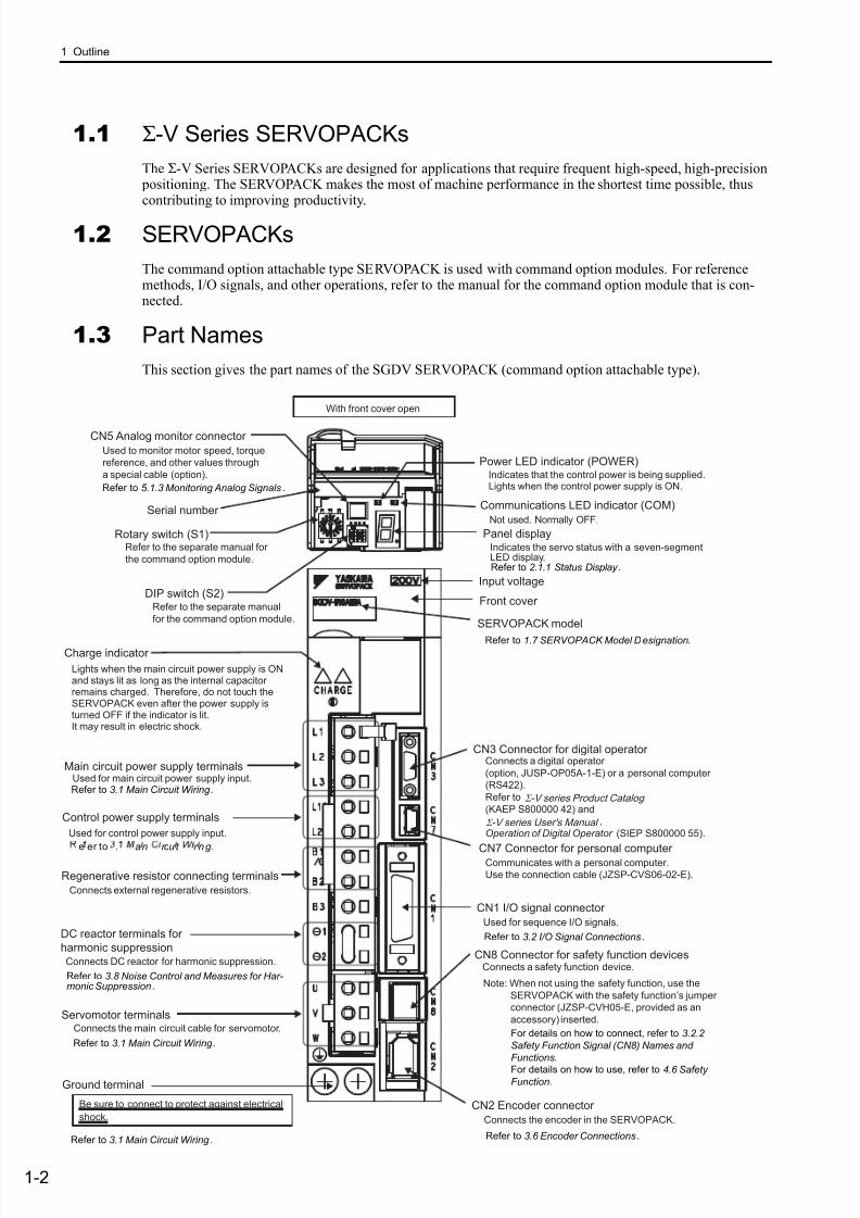
1.3 Part Names
This section gives the part names of the SGDV SERVOPACK (command option attachable type).
CN5 Analog monitor connector
Used to monitor motor speed, torque
reference, and other values through
a special cable (option).
Panel display
Connects external regenerative resistors.
Used for control power supply input.
Charge indicator
Front cover
CN3 Connector for digital operatorConnects a digital operator
(option, JUSP-OP05A-1-E) or a personal computer
(RS422).
Refer to
(KAEP S800000 42) and
,
Operation of Digital Operator (SIEP S800000 55).
CN1 I/O signal connector
Used for sequence I/O signals.
CN7 Connector for personal computerCommunicates with a personal computer.
Use the connection cable (JZSP-CVS06-02-E).
CN2 Encoder connector
Connects the encoder in the SERVOPACK.
Ground terminal
Main circuit power supply terminalsUsed for main circuit power supply input.
Control power supply terminals
Servomotor terminalsConnects the main circuit cable for servomotor.
SERVOPACK model
Regenerative resistor connecting terminals
Input voltage
CN8 Connector for safety function devicesConnects a safety function device.
DC reactor terminals for
harmonic suppressionConnects DC reactor for harmonic suppression.
With front cover open
Lights when the main circuit power supply is ONand stays lit as long as the internal capacitorremains charged. Therefore, do not touch theSERVOPACK even after the power supply isturned OFF if the indicator is lit.It may result in electric shock.
Σ -V series Product Catalog
Σ -V series User's Manual
Note: When not using the safety function, use the
SERVOPACK with the safety function’s jumper
connector (JZSP-CVH05-E, provided as an
accessory) inserted.
Serial number
Rotary switch (S1)
DIP switch (S2)
Indicates the servo status with a seven-segmentLED display.
Power LED indicator (POWER)Indicates that the control power is being supplied.Lights when the control power supply is ON.
Communications LED indicator (COM)
Be sure to connect to protect against electrical
shock.
Refer to the separate manual for
the command option module.
Refer to the separate manual
for the command option module.
Not used. Normally OFF.
Refer to 2.1.1 Status Display .
e er to . a n rcu t r n g .
Refer to 3.1 Main Circuit Wiring .
Refer to 3.1 Main Circuit Wiring .
Refer to 3.1 Main Circuit Wiring .
Refer to 3.2 I/O Signal Connections.
Refer to 1.7 SERVOPACK Model Designation.
Refer to 3.6 Encoder Connections.
For details on how to connect, refer to 3.2.2
Safety Function Signal (CN8) Names and
Functions.
For details on how to use, refer to 4.6 SafetyFunction.
Refer to 5.1.3 Monitoring Analog Signals.
Refer to 3.8 Noise Control and Measures for Har-monic Suppression.
7/17/2019 Manual Yaskawa_servo_drive.pdf
http://slidepdf.com/reader/full/manual-yaskawaservodrivepdf 21/328
1.4 SERVOPACK Ratings and Specifications
1-3
O u t l i n e
1.4 SERVOPACK Ratings and Specifications
This section describes the ratings and specifications of SERVOPACKs.
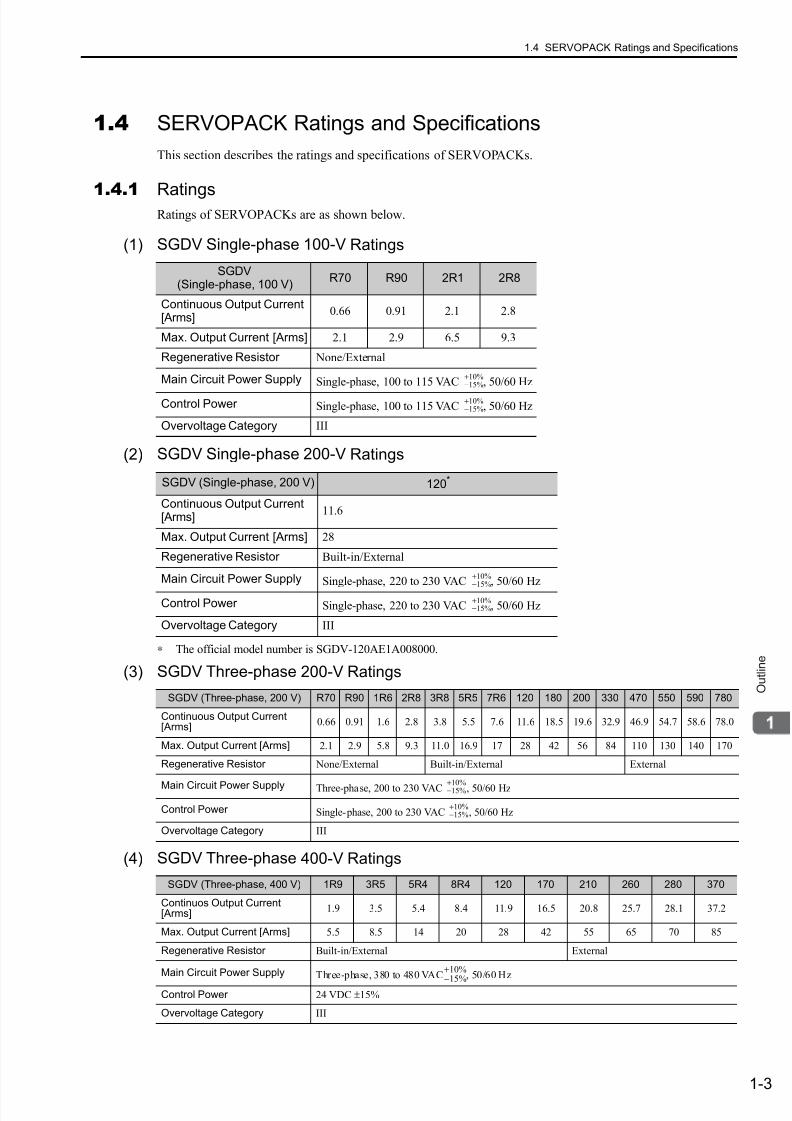
1.4.1RatingsRatings of SERVOPACKs are as shown below.
(1) SGDV Single-phase 100-V Ratings
(2) SGDV Single-phase 200-V Ratings
∗ The official model number is SGDV-120AE1A008000.
(3) SGDV Three-phase 200-V Ratings
(4) SGDV Three-phase 400-V Ratings
SGDV(Single-phase, 100 V)
R70 R90 2R1 2R8
Continuous Output Current[Arms]
0.66 0.91 2.1 2.8
Max. Output Current [Arms] 2.1 2.9 6.5 9.3
Regenerative Resistor None/External
Main Circuit Power Supply Single-phase, 100 to 115 VAC , 50/60 Hz
Control Power Single-phase, 100 to 115 VAC , 50/60 Hz
Overvoltage Category III
SGDV (Single-phase, 200 V) 120*
Continuous Output Current[Arms]
11.6
Max. Output Current [Arms] 28
Regenerative Resistor Built-in/External
Main Circuit Power Supply Single-phase, 220 to 230 VAC , 50/60 Hz
Control Power Single-phase, 220 to 230 VAC , 50/60 Hz
Overvoltage Category III
+10%−15%
+10%−15%
+10%−15%
+10%−15%
SGDV (Three-phase, 200 V) R70 R90 1R6 2R8 3R8 5R5 7R6 120 180 200 330 470 550 590 780
Continuous Output Current[Arms]
0.66 0.91 1.6 2.8 3.8 5.5 7.6 11.6 18.5 19.6 32.9 46.9 54.7 58.6 78.0
Max. Output Current [Arms] 2.1 2.9 5.8 9.3 11.0 16.9 17 28 42 56 84 110 130 140 170
Regenerative Resistor None/External Built-in/External External
Main Circuit Power Supply Three-phase, 200 to 230 VAC , 50/60 Hz
Control Power Single-phase, 200 to 230 VAC , 50/60 Hz
Overvoltage Category III
SGDV (Three-phase, 400 V) 1R9 3R5 5R4 8R4 120 170 210 260 280 370
Continuos Output Current[Arms]
1.9 3.5 5.4 8.4 11.9 16.5 20.8 25.7 28.1 37.2
Max. Output Current [Arms] 5.5 8.5 14 20 28 42 55 65 70 85
Regenerative Resistor Built-in/External External
Main Circuit Power Supply Three-phase, 380 to 480 VAC , 50/60 Hz
Control Power 24 VDC ±15%
Overvoltage Category III
+10%−15%
+10%−15%
+10%
−15%

7/17/2019 Manual Yaskawa_servo_drive.pdf
http://slidepdf.com/reader/full/manual-yaskawaservodrivepdf 22/328
1 Outline
1.4.2 Basic Specifications
1-4
1.4.2 Basic Specifications
Basic specifications of SERVOPACKs are shown below.
Control Method IGBT-PWM (sine-wave driven)
Feedback Serial encoder:13-bit (incremental), 17-bit, 20-bit (incremental/absolute)
OperatingConditions
Surrounding Air/StorageTemperature
0 to +55°C/ -20 to +85°C
Ambient/StorageHumidity
90% RH or less (with no condensation)
Vibration/ShockResistance 4.9 m/s2 / 19.6 m/s2
Protection Class/Pollution Degree
Protection class: IP10, Pollution degree: 2
An environment that satisfies the following conditions.
• Free of corrosive or explosive gases
• Free of exposure to water, oil or chemicals
• Free of dust, salts or iron dust Altitude 1000 m or less
OthersFree of static electricity, strong electromagnetic fields, magnetic fields orexposure to radioactivity
Applicable StandardsUL508C
EN50178, EN55011 group 1 class A, EN61000-6-2, EN61800-3, EN61800-5-1, EN954-1, IEC61508-1 to 4
Configuration Base-mounted *1
Perfor-mance
Speed Control Range 1:5000
Speed
Regu-lation∗2
LoadFluctuation
0 to 100% load: ±0.01% max. (at rated speed)
VoltageFluctuation Rated voltage ±10%: 0% (at rated speed)
TemperatureFluctuation
25 ± 25 °C: ±0.1% max. (at rated speed)
Torque ControlTolerance(Repeatability)
±1%
I/OSignals
Encoder Output PulsesPhase-A, -B, -C: line driverEncoder output pulse: any setting ratio
SequenceInput
Input
Signalswhich canbe allocated
NumberofChannels
7 channels
Functions
The signal allocation and positive/negative logic can bemodified.
Forward run prohibited (P-OT), reverse run prohibited (N-OT), forward external torque limit (/P-CL), reverse externaltorque limit (/N-CL), general-purpose input signal (/SI0 to /
SI6)*3
SequenceOutput
FixedOutput
Servo alarm (ALM)
OutputSignalswhich can
be allocated
NumberofChannels
3 channels
Functions
The signal allocation and positive/negative logic can be modi-fied.
Positioning completion (/COIN), speed coincidence detection(/V-CMP), servomotor rotation detection (/TGON), servoready (/S-RDY), torque limit detection (/CLT), speed limitdetection (/VLT), brake (/BK), warning (/WARN), near (/ NEAR)
7/17/2019 Manual Yaskawa_servo_drive.pdf
http://slidepdf.com/reader/full/manual-yaskawaservodrivepdf 23/328
1.4 SERVOPACK Ratings and Specifications
1-5
O u t l i n e∗1. Rack mounting and duct-ventilated type available as an option.
∗2. Speed regulation by load fluctuation is defined as follows:
∗3. For information on functions, refer to the manual of the connected command option module.
(cont’d)
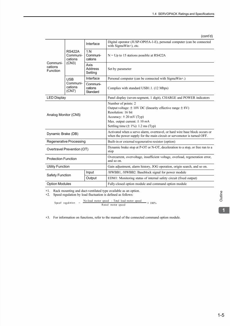
Communi-cationsFunction
RS422A
Communi-cations(CN3)
InterfaceDigital operator (JUSP-OP05A-1-E), personal computer (can be connectedwith SigmaWin+), etc.
1:N
Communi-cations N = Up to 15 stations possible at RS422A
Axis AddressSetting
Set by parameter
USBCommuni-cations(CN7)
Interface Personal computer (can be connected with SigmaWin+.)
Communi-cationsStandard
Complies with standard USB1.1. (12 Mbps)
LED Display Panel display (seven-segment, 1 digit), CHARGE and POWER indicators
Analog Monitor (CN5)
Number of points: 2
Output voltage: ± 10V DC (linearity effective range ± 8V)
Resolution: 16 bit
Accuracy: ± 20 mV (Typ)
Max. output current: ± 10 mA
Settling time (± 1%): 1.2 ms (Typ)
Dynamic Brake (DB)Activated when a servo alarm, overtravel, or hard wire base block occurs orwhen the power supply for the main circuit or servomotor is turned OFF.
Regenerative Processing Built-in or external regenerative resistor (option)
Overtravel Prevention (OT)Dynamic brake stop at P-OT or N-OT, deceleration to a stop, or free run to astop
Protection FunctionOvercurrent, overvoltage, insufficient voltage, overload, regeneration error,and so on.
Utility Function Gain adjustment, alarm history, JOG operation, origin search, and so on.
Safety FunctionInput /HWBB1, /HWBB2: Baseblock signal for power module
Output EDM1: Monitoring status of internal safety circuit (fixed output)
Option Modules Fully-closed option module and command option module
Speed regulation = No-load motor speed Total load motor speed
Rated motor speed × 100%
-
7/17/2019 Manual Yaskawa_servo_drive.pdf
http://slidepdf.com/reader/full/manual-yaskawaservodrivepdf 24/328
1 Outline
1.5.1 Single-phase 100-V, SGDV-R70FE1A, -R90FE1A, -2R1FE1A Models
1-6
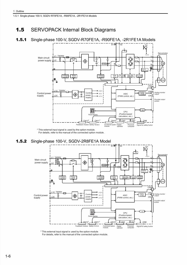
1.5 SERVOPACK Internal Block Diagrams
1.5.1 Single-phase 100-V, SGDV-R70FE1A, -R90FE1A, -2R1FE1A Models
1.5.2 Single-phase 100-V, SGDV-2R8FE1A Model
L1
B1/ B2
L2
L1C
L2C
+
−
+
−
U
V
W
±12 V
+5 V
+17 V
CHARGE M
-
+
+12 V
ENC
Safe ty modu le Command op tionmodule
Feedback module
CN11*CN12* CN10* CN3 CN7 CN8
CN2
I/O
CN1
CN5
Encoder outputpulses
Main circuit
power supply
Servomotor
Fan
Varistor
Voltagesensor
Varistor
Controlpower
supply
CPU
(Position/speed
calculation, etc.)Panel display
Digitaloperator
Personalcomputer
Signal for safety fuction
Analog monitor output ASIC
(PWM control, etc.)
Analogvoltageconverter
Currentsensor
Dynamic
brake circuit
Voltagesensor
Gate driveovercurrentprotector
Temperaturesensor
+
−
Gatedrive
Relaydrive
Control powersupply
* This external input signal is used by the option module.
For details, refer to the manual of the connected option module.
L1
B1/ B2
L2
L1C
L2C
U
V
WCHARGE M
+12 V
ENC
CN2
CN11*CN12* CN10* CN3 CN7 CN8
I/O
CN1
CN5
+
−
±12 V
+5 V
+17 V
Servomotor
Fan
Varistor
Voltagesensor
Varistor
Control
power
supply
CPU
(Position/speed
calculation, etc.)Panel display
Digitaloperator
Personalcomputer
Signal for safety fuction
Analog monitoroutput ASIC
(PWM control, etc.)
Analogvoltageconverter
Currentsensor
Dynamic
brake circuit
Gate driveovercurrentprotector
Temperaturesensor
+
−
Voltagesensor
Gatedrive
Relaydrive
Main circuit
power supply
Control powersupply
Safety module Command optionmodule
Feedback module
Encoder outputpulses
* This external input signal is used by the option module.For details, refer to the manual of the connected option module.
7/17/2019 Manual Yaskawa_servo_drive.pdf
http://slidepdf.com/reader/full/manual-yaskawaservodrivepdf 25/328
1.5 SERVOPACK Internal Block Diagrams
1-7
O u t l i n e
1.5.3 Single-phase 200-V, SGDV-120AE1A008000 Model
1.5.4 Three-phase 200-V, SGDV-R70AE1A, -R90AE1A, -1R6AE1A Models
L1
B1/ B2 B3
L2
1
2
L1C
L2C
U
V
W
ENC
ML3
CHARGE
CN2
CN11*CN12* CN10* CN3 CN7 CN8
I/O
CN1
CN5
±12 V±12 V
Servomotor
Fan 1
Varistor
Voltagesensor
Varistor
Control
power
supply
CPU
(Position/speed
calculation, etc.)Panel display
Digitaloperator
Personalcomputer
Signal for safety fuction
Analog monitor output ASIC
(PWM control, etc.)
Analogvoltageconverter
Currentsensor
Dynamic
brake circuit
Voltagesensor
Gate driveRelaydrive
Main circuit
power supply
Control power
supply
Sa fety module Command optionmodule
Feedback module
Encoder outputpulses
Fan 2
Overheat protector,overcurrent protector
+15 V × 4
+5 V
+
−
±12 V
+
−
* This external input signal is used by the option module.
For details, refer to the manual of the connected option module.
L1
B1/ B2 B3
L2
L3
1
2
L1C
L2C
U
V
W
ENC
MCHARGE
CN2
+12 V
CN11*CN12* CN10* CN3 CN7 CN8
I/O
CN1
CN5
+
−
±12 V
+5 V
+17 V
Servomotor
Fan
Varistor
Voltagesensor
Varistor
Control
power
supply
CPU
(Position/speed
calculation, etc.)Panel display
Digitaloperator
Personalcomputer
Signal for safety fuction
Analog monitor output ASIC
(PWM control, etc.)
Analogvoltageconverter
Currentsensor
Dynamic
brake circuit
Gate driveovercurrentprotector
Temperaturesensor
+
−
Voltagesensor
Gatedrive
Relaydrive
Main circuit
power supply
Control powersupply
S afe ty modu le Command op tionmodule
Feedback module
Encoder outputpulses
* This external input signal is used by the option module.For details, refer to the manual of the connected option module.

7/17/2019 Manual Yaskawa_servo_drive.pdf
http://slidepdf.com/reader/full/manual-yaskawaservodrivepdf 26/328
1 Outline
1.5.5 Three-phase 200-V, SGDV-2R8AE1A Model
1-8
1.5.5 Three-phase 200-V, SGDV-2R8AE1A Model
1.5.6 Three-phase 200-V, SGDV-3R8AE1A, -5R5AE1A, -7R6AE1A Models
L1
B1/ B2 B3
L2
L3
1
2
L1C
L2C
U
V
W
+17 V
+5 V
ENC
MCHARGE
CN2
+12 V
CN11*CN12* CN10* CN3 CN7 CN8
I/O
CN1
CN5
+
−
±12 V
Servomotor
Fan
Varistor
Voltagesensor
Varistor Control
power
supply
CPU
(Position/speed
calculation, etc.)Panel display
Digitaloperator
Personalcomputer
Signal for safety fuction
Analog monitor output ASIC
(PWM control, etc.)
Analogvoltageconverter
Currentsensor
Dynamic
brake circuit
Gate driveovercurrentprotector
Temperaturesensor
+
−
Voltagesensor
Gatedrive
Relaydrive
Main circuit
power supply
Control powersupply
Safety module Command optionmodule
Feedback module
Encoder outputpulses
* This external input signal is used by the option module.
For details, refer to the manual of the connected option module.
L1
B1/ B2 B3
L2
L3
1
2
L1C
L2C
U
V
W
+17 V
+5 V
ENC
MCHARGE
CN2
CN11*CN12* CN10* CN3 CN7 CN8
I/O
CN1
CN5
+
−
±12 V
Servomotor
Fan
Varistor
Voltagesensor
Varistor Control
power
supply
CPU
(Position/speed
calculation, etc.)Panel display
Digitaloperator
Personalcomputer
Signal for safety fuction
Analog monitor output ASIC
(PWM control, etc.)
Analogvoltageconverter
Currentsensor
Dynamic
brake circuit
Gate driveovercurrentprotector
Temperaturesensor
+
−
Voltagesensor
Gatedrive
Relaydrive
±12 V
Main circuit
power supply
Control powersupply
Safety module Command optionmodule
Feedback module
Encoder outputpulses
* This external input signal is used by the option module.
For details, refer to the manual of the connected option module.
7/17/2019 Manual Yaskawa_servo_drive.pdf
http://slidepdf.com/reader/full/manual-yaskawaservodrivepdf 27/328
1.5 SERVOPACK Internal Block Diagrams
1-9
O u t l i n e
1.5.7 Three-phase 200-V, SGDV-120AE1A Model
1.5.8 Three-phase 200-V, SGDV-180AE1A, -200AE1A Models
L1
B1/ B2 B3
L2
L3
1
2
L1C
L2C
U
V
W
ENC
MCHARGE
+15 V × 4
+5 V
CN2
CN11*CN12* CN10* CN3 CN7 CN8
I/O
CN1
CN5
+
−
±12 V
Servomotor
Fan
Varistor
Voltagesensor
Varistor Control
power
supply
CPU
(Position/speed
calculation, etc.)Panel display
Digitaloperator
Personalcomputer
Signal for safety fuction
Analog monitor output ASIC
(PWM control, etc.)
Analogvoltageconverter
Currentsensor
Dynamic
brake circuit
+
−
Voltagesensor
Overheat protector,overcurrent protector
Gate driveRelaydrive
±12 V
Main circuit
power supply
Control powersupply
Safety module Command optionmodule
Feedback module
Encoder output
pulses
* This external input signal is used by the option module.
For details, refer to the manual of the connected option module.
L1
B1/ B2 B3
L2
L3
1
2
L1C
L2C
U
V
W
ENC
MCH ARGE
+15 V × 4
+5 V
CN2
CN11*CN12* CN10* CN3 CN7 CN8
I/O
CN1
CN5
* This external input signal is used by the option module.
For details, refer to the manual of the connected option module.
+
−
±12 V
Servomotor
Varistor
Voltagesensor
Varistor
Control
power
supply
CPU
(Position/speed
calculation, etc.)Panel display
Digitaloperator
Personalcomputer
Signal for safety fuction
Analog monitor output ASIC
(PWM control, etc.)
Analogvoltageconverter
Currentsensor
Dynamic
brake circuit
+
−
Voltagesensor
Overheat protector,overcurrent protector
Gate driveRelaydrive
Fan 2Fan 1
±12 V ±12 V
Main circuit
power supply
Control powersupply
Safety module Command optionmodule
Feedback module
Encoder output
pulses

7/17/2019 Manual Yaskawa_servo_drive.pdf
http://slidepdf.com/reader/full/manual-yaskawaservodrivepdf 28/328
1 Outline
1.5.9 Three-phase 200-V, SGDV-330AE1A Model
1-10
1.5.9 Three-phase 200-V, SGDV-330AE1A Model
1.5.10 Three-phase 200-V, SGDV-470AE1A, -550AE1A Models
L1
B1/ B2 B3
L2
L3
1
2
L1C
L2C
U
V
W
ENC
M
+15 V × 4
+5 V
CN2
CN11*CN12* CN10* CN3 CN7 CN8
I/O
CN1
CN5
* This external input signal is used by the option module.
For details, refer to the manual of the connected option module.
+
−
±12 V
Servomotor
Varistor
Varistor
Control
power
supply
CPU
(Position/speed
calculation, etc.)Panel display
Digitaloperator
Personalcomputer
Signal for safety fuction
Analog monitor output ASIC
(PWM control, etc.)
Analogvoltageconverter
Gate drive
+
−
Fan 2Fan 1
Voltagesensor
CHARGE
Thyristor drive
Currentsensor
Dynamic
brake circuit
Voltagesensor
Overheat protector,overcurrent protector
Temperaturesenser
±12 V ±12 V
Main circuit
power supply
Control powersupply
Safety mod ule Command optionmodule
Feedback module
Encoder outputpulses
CN2
CN11*CN12* CN10* CN3 CN7 CN8
I/O
CN1
CN5
L1
B1/ B2
L2
L3
L1C
L2C
U
V
W
ENC
MCH ARGE
+15 V × 4
+5 V
+
−
±12 V
Servomotor
Varistor
Varistor Control
power
supply
CPU
(Position/speed
calculation, etc.)Panel display
Digitaloperator
Personalcomputer
Signal for safety fuction
Analog monitor output ASIC
(PWM control, etc.)
Analogvoltageconverter
Gate drive
+
−
Fan 2Fan 1
Voltagesensor
Thyristor drive
Currentsensor
Dynamic
brake circuit
Voltagesensor
Overheat protector,overcurrent protector
Temperaturesenser
±12 V ±12 V
Fan 3
±12 V
Main circuit
power supply
Control powersupply
Safety module Command optionmodule
Feedback module
Encoder output
pulses
* This external input signal is used by the option module.
For details, refer to the manual of the connected option module.
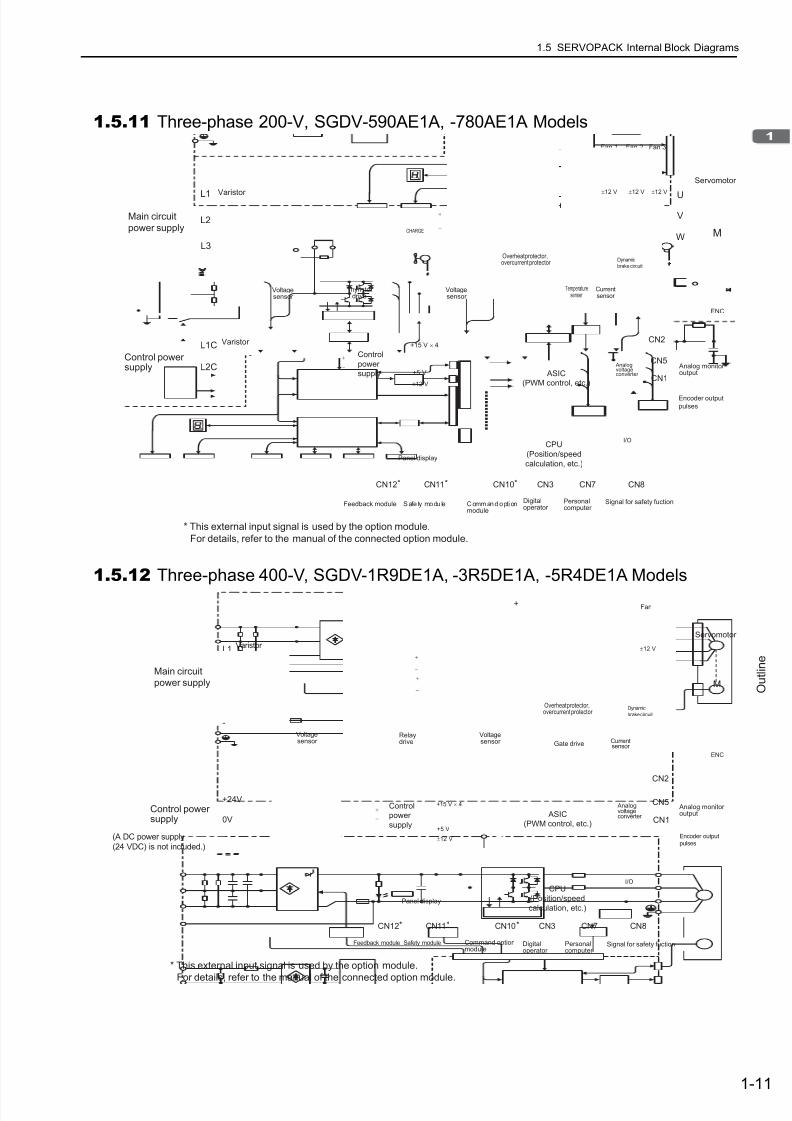
7/17/2019 Manual Yaskawa_servo_drive.pdf
http://slidepdf.com/reader/full/manual-yaskawaservodrivepdf 29/328
1.5 SERVOPACK Internal Block Diagrams
1-11
O u t l i n e
1.5.11 Three-phase 200-V, SGDV-590AE1A, -780AE1A Models
1.5.12 Three-phase 400-V, SGDV-1R9DE1A, -3R5DE1A, -5R4DE1A Models
CN11*CN12* CN10* CN3 CN7 CN8
I/O
CN1
CN5
L1
B1/ B2
L2
L3
L1C
L2C
U
V
W
CN2
ENC
MCHARGE
+15 V × 4
+5 V
+
−
±12 V
Servomotor
Varistor
Varistor
Control
power
supply
CPU
(Position/speed
calculation, etc.)Panel display
Digitaloperator
Personalcomputer
Signal for safety fuction
Analog monitor output ASIC
(PWM control, etc.)
Analogvoltageconverter
Gate drive
+
−
Fan 2Fan 1
Voltagesensor
Thyristor drive
Currentsensor
Dynamic
brake circuit
Voltagesensor
Overheat protector,overcurrent protector
Temperaturesenser
±12 V ±12 V
Fan 3
±12 V
Main circuit
power supply
Control powersupply
S afe ty modu le C ommand opti onmodule
Feedback module
Encoder output
pulses
* This external input signal is used by the option module.
For details, refer to the manual of the connected option module.
L1
B1/ B2 B3
L2
L3
1
2
+24V
0V
U
V
W
+15 V × 4
ENC
MCH ARGE
-
+
-
+5 V
CN2
Safety module Command optionmodule
Feedback module
CN11*CN12* CN10* CN3 CN7 CN8
I/O
CN1
CN5
Encoder outputpulses
Main circuit
power supply
(A DC power supply
(24 VDC) is not included.)
+
−
±12 V
Servomotor
Varistor
Voltagesensor
Control
power
supply
CPU
(Position/speed
calculation, etc.)Panel display
Digitaloperator
Personalcomputer
Signal for safety fuction
Analog monitor output ASIC
(PWM control, etc.)
Analogvoltageconverter
Currentsensor
Dynamic
brake circuit
+
−
Voltagesensor
Overheat protector,overcurrent protector
Gate drive
Relaydrive
Fan
±12 V
Control powersupply
+
−
* This external input signal is used by the option module.
For details, refer to the manual of the connected option module.

7/17/2019 Manual Yaskawa_servo_drive.pdf
http://slidepdf.com/reader/full/manual-yaskawaservodrivepdf 30/328
1 Outline
1.5.13 Three-phase 400-V, SGDV-8R4DE1A, -120DE1A Models
1-12
1.5.13 Three-phase 400-V, SGDV-8R4DE1A, -120DE1A Models
1.5.14 Three-phase 400-V, SGDV-170DE1A Model
L1
B1/ B2 B3
L2
L3
12
+24V
0V
U
V
W
+15 V × 4
ENC
MCHARGE
+5 V
CN2
CN11*CN12* CN10* CN3 CN7 CN8
I/O
CN1
CN5
+
−
±12 V
Servomotor
Varistor
Voltagesensor
Control
power
supply
CPU
(Position/speed
calculation, etc.)Panel display
Digitaloperator
Personalcomputer
Signal for safety fuction
Analog monitor output ASIC
(PWM control, etc.)
Analogvoltageconverter
Currentsensor
Dynamic
brake circuit
+
−
Voltagesensor
Overheat protector,overcurrent protector
Gate driveRelaydrive
Fan 2Fan 1
±12 V ±12 V
+
−
Main circuit
power supply
Control powersupply
Safety module Command optionmodule
Feedback module
Encoder outputpulses
(A DC power supply
(24 VDC) is not included.)
* This external input signal is used by the option module.
For details, refer to the manual of the connected option module.
L1
B1/ B2 B3
L2
L3
1
2
+24V
0V
U
V
W
ENC
MCHARGE
+15 V × 4
+5 V
CN2
CN11*CN12* CN10* CN3 CN7 CN8
I/O
CN1
CN5
* This external input signal is used by the option module.
For details, refer to the manual of the connected option module.
+
−
±12 V
Servomotor
Varistor
Voltagesensor
Control
power
supply
CPU
(Position/speed
calculation, etc.)Panel display
Digitaloperator
Personalcomputer
Signal for safety fuction
Analog monitor output ASIC
(PWM control, etc.)
Analogvoltageconverter
Currentsensor
Dynamic
brake circuit
+
−
Voltagesensor
Overheat protector,overcurrent protector
Gate driveRelaydrive
Fan
±12 V
+
−
Safety mo dule Command optionmodule
Feedback module
Encoder output
pulses
Main circuit
power supply
Control powersupply
(A DC power supply(24 VDC) is not included.)
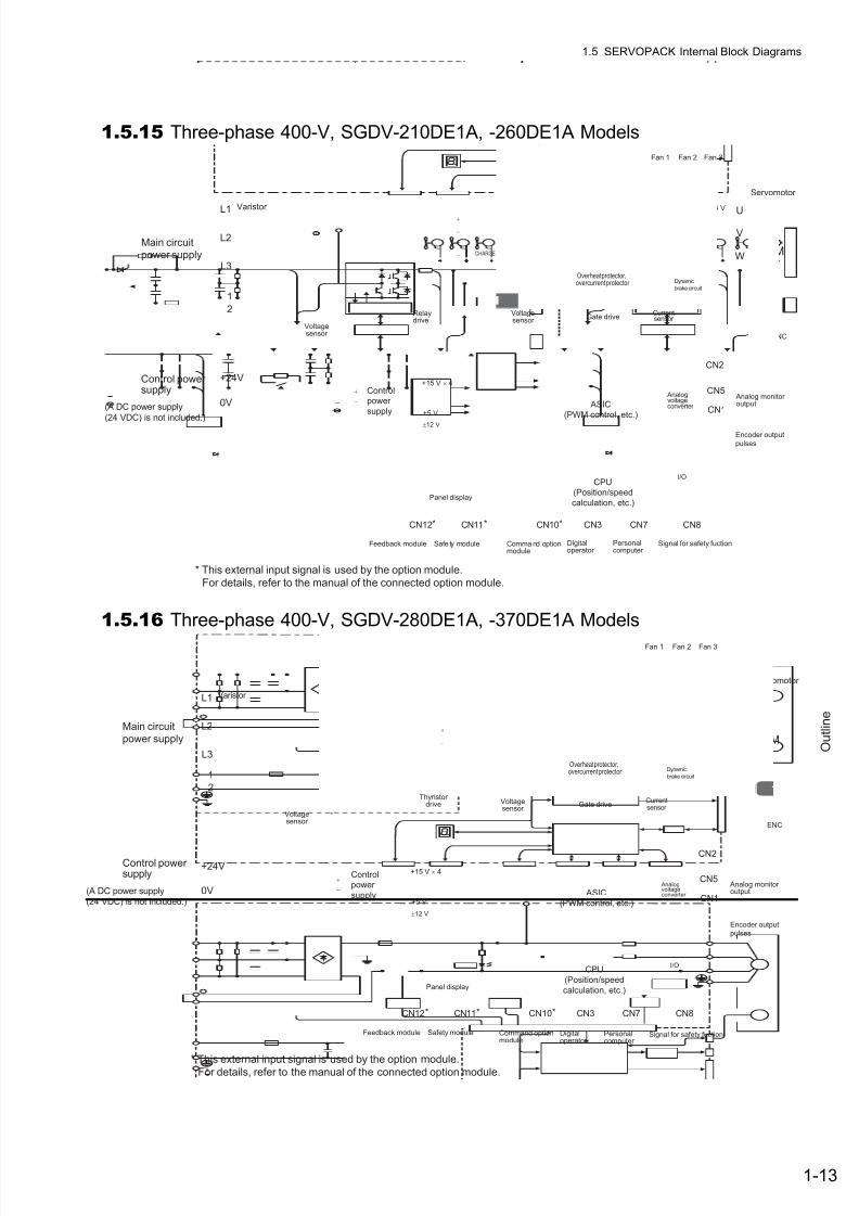
7/17/2019 Manual Yaskawa_servo_drive.pdf
http://slidepdf.com/reader/full/manual-yaskawaservodrivepdf 31/328
1.5 SERVOPACK Internal Block Diagrams
1-13
O u t l i n e
1.5.15 Three-phase 400-V, SGDV-210DE1A, -260DE1A Models
1.5.16 Three-phase 400-V, SGDV-280DE1A, -370DE1A Models
CN2
CN11*CN12* CN10* CN3 CN7 CN8
I/O
CN1
CN5
L1
B1/ B2
L2
L3
1
2
+24V
0V
U
V
W
ENC
MCHARGE
+15 V × 4
+5 V
+24 V +24 V +24 V
+
−
±12 V
Servomotor
Varistor
Voltagesensor
Control
power
supply
CPU
(Position/speed
calculation, etc.)Panel display
Digitaloperator
Personalcomputer
Signal for safety fuction
Analog monitor output ASIC
(PWM control, etc.)
Analogvoltageconverter
Currentsensor
Dynamic
brake circuit
+
−
Voltagesensor
Overheat protector,overcurrent protector
Gate driveRelaydrive
Fan 2Fan 1 Fan 3
+
−
Safe ty module Comma nd optionmodule
Feedback module
Encoder output
pulses
Main circuit
power supply
Control powersupply
(A DC power supply
(24 VDC) is not included.)
* This external input signal is used by the option module.
For details, refer to the manual of the connected option module.
CN2
CN11*CN12* CN10* CN3 CN7 CN8
I/O
CN1
CN5
L1
B1/ B2
L2
L3
1
2
+24V
0V
U
V
W
ENC
MCHARGE
+15 V × 4
+5 V
+24 V +24 V +24 V
+
−
±12 V
Servomotor
Varistor
Control
power
supply
CPU
(Position/speed
calculation, etc.)Panel display
Digitaloperator
Personalcomputer
Signal for safety fuction
Analog monitor output ASIC
(PWM control, etc.)
Analogvoltageconverter
Gate drive
+
−
Fan 2Fan 1
Voltagesensor
Thyristor drive
Currentsensor
Dynamic
brake circuit
Voltagesensor
Overheat protector,overcurrent protector
Fan 3
+
−
Safety module Command optionmodule
Feedback module
Encoder output
pulses
Main circuit
power supply
Control powersupply
(A DC power supply(24 VDC) is not included.)
* This external input signal is used by the option module.
For details, refer to the manual of the connected option module.

7/17/2019 Manual Yaskawa_servo_drive.pdf
http://slidepdf.com/reader/full/manual-yaskawaservodrivepdf 32/328
1 Outline
1.6.1 Connecting to SGDV-FE1A SERVOPACK
1-14
1.6 Examples of Servo System Configurations
This section describes examples of basic servo system configuration.
1.6.1Connecting to SGDV-
FE1A SERVOPACK
∗1. Use a 24-VDC power supply. (not included.)∗2. Before connecting an external regenerative resistor to the SERVOPACK, refer to 3.7 Regenerative Resistors Connec-
tions.
Option module
R T
External LED indicator, externaldevice, etc.
SGDV-FE1A
SERVOPACK
SGMJV/SGMAV/SGMPS/SGMCS
Servomotor
Power supply
Single-phase 100 VAC
100 VAC
Noise filter
Molded-casecircuit breaker(MCCB)
Used to eliminateexternal noise from
the power line.
MagneticcontactorTurns the servoON and OFF.Install a surgeabsorber.
Brake power supply*1
Magnetic contactor
Regenerativeresistor*2
Used for a servomotorwith a brake.
Turns the brake power supply
ON and OFF.Install a surge absorber.
Motor maincircuit cable
Encoder cable
Battery case(when an absoluteencoder is used.)
When not using the safetyfunction, use the SERVOPACKwith the safety function’s jumper connector (JZSP-CVH05-E,provided as an accessory)inserted.
When using the safety function,insert a connection cablespecifically for the safety function.
Safety functiondevices
I/O signal cable
Connection cablefor digital operator
Connection cablefor personal computer
Digitaloperator
Personalcomputer
Protects the powersupply line byshutting the circuitOFF whenovercurrent isdetected.
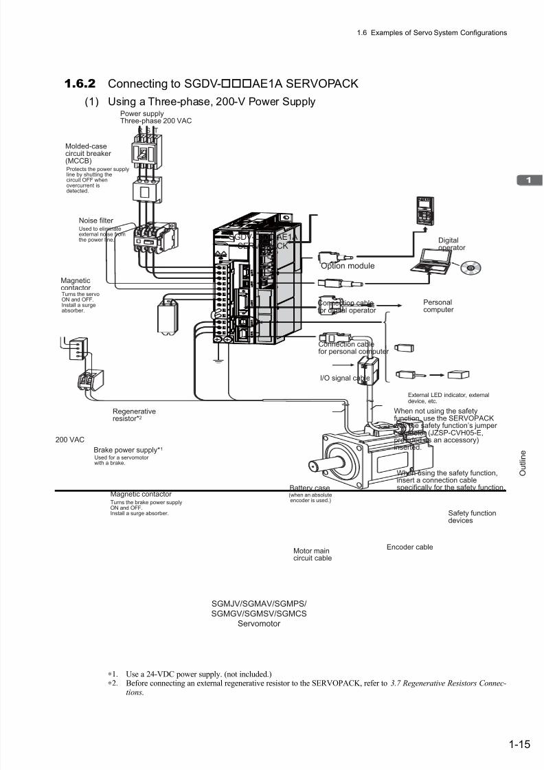
7/17/2019 Manual Yaskawa_servo_drive.pdf
http://slidepdf.com/reader/full/manual-yaskawaservodrivepdf 33/328
1.6 Examples of Servo System Configurations
1-15
O u t l i n e
1.6.2 Connecting to SGDV- AE1A SERVOPACK
(1) Using a Three-phase, 200-V Power Supply
∗1. Use a 24-VDC power supply. (not included.)∗2. Before connecting an external regenerative resistor to the SERVOPACK, refer to 3.7 Regenerative Resistors Connec-
tions.
R S T
200 VAC
Option module
External LED indicator, externaldevice, etc.
SGDV- AE1ASERVOPACK
SGMJV/SGMAV/SGMPS/
SGMGV/SGMSV/SGMCS
Servomotor
Noise filter
Molded-casecircuit breaker(MCCB)Protects the power supplyline by shutting thecircuit OFF whenovercurrent isdetected.
Used to eliminateexternal noise fromthe power line.
MagneticcontactorTurns the servoON and OFF.Install a surgeabsorber.
Brake power supply*1
Magnetic contactor
Regenerativeresistor*2
Used for a servomotorwith a brake.
Turns the brake power supplyON and OFF.Install a surge absorber.
Motor maincircuit cable
Encoder cable
Battery case(when an absoluteencoder is used.)
When not using the safetyfunction, use the SERVOPACKwith the safety function’s jumper connector (JZSP-CVH05-E,provided as an accessory)inserted.
When using the safety function,insert a connection cablespecifically for the safety function.
Safety functiondevices
I/O signal cable
Connection cablefor digital operator
Connection cablefor personal computer
Digitaloperator
Personalcomputer
Power supplyThree-phase 200 VAC

7/17/2019 Manual Yaskawa_servo_drive.pdf
http://slidepdf.com/reader/full/manual-yaskawaservodrivepdf 34/328
1 Outline
1.6.2 Connecting to SGDV- AE1A SERVOPACK
1-16
(2) Using a Single-phase, 200-V Power Supply
The Σ-V Series SERVOPACK for a 200-V power supply input has input specifications for a three-phase power supply, butsome models can also be used with a single-phase 200-V power supply. For details, refer to 3.1.3 Using the SERVOPACKwith Single-phase, 200-V Power Input.
∗1. Use a 24-VDC power supply. (not included.)∗2. Before connecting an external regenerative resistor to the SERVOPACK, refer to 3.7 Regenerative Resistors Connec-
tions.
R T
Option module
External LED indicator, externaldevice, etc.
SGDV- AE1ASERVOPACK
SGMJV/SGMAV/SGMPS/SGMCS
Servomotor
Power supply
Single-phase 200 VAC
200 VAC
Noise filter
Molded-casecircuit breaker(MCCB)Protects the power supplyline by shutting thecircuit OFF whenovercurrent isdetected.
Used to eliminateexternal noise fromthe power line.
MagneticcontactorTurns the servoON and OFF.Install a surgeabsorber.
Brake power supply*1
Magnetic contactor
Regenerativeresistor*2
Used for a servomotorwith a brake.
Turns the brake power supplyON and OFF.Install a surge absorber.
Motor maincircuit cable
Encoder cable
Battery case(when an absoluteencoder is used.)
When not using the safetyfunction, use the SERVOPACKwith the safety function’s jumper connector (JZSP-CVH05-E,provided as an accessory)inserted.
When using the safety function,insert a connection cablespecifically for the safety function.
Safety functiondevices
I/O signal cable
Connection cablefor digital operator
Connection cablefor personal computer
Digitaloperator
Personalcomputer
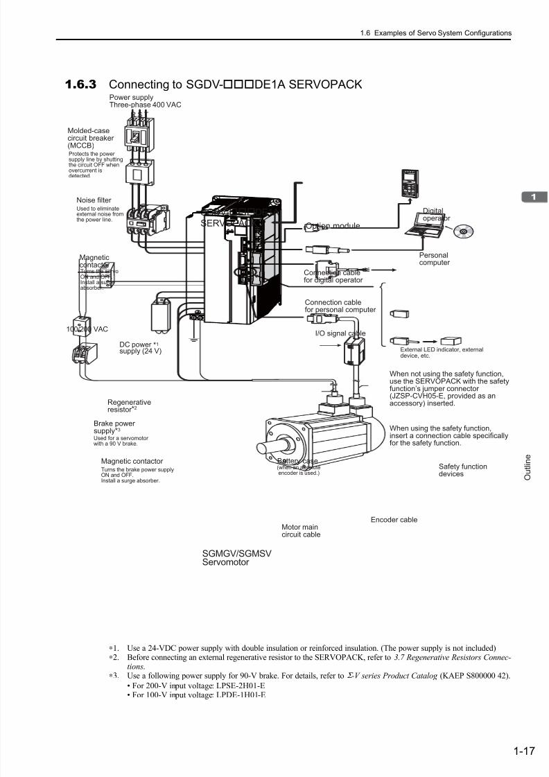
7/17/2019 Manual Yaskawa_servo_drive.pdf
http://slidepdf.com/reader/full/manual-yaskawaservodrivepdf 35/328
1.6 Examples of Servo System Configurations
1-17
O u t l i n e
1.6.3 Connecting to SGDV-DE1A SERVOPACK
∗1. Use a 24-VDC power supply with double insulation or reinforced insulation. (The power supply is not included)∗2. Before connecting an external regenerative resistor to the SERVOPACK, refer to 3.7 Regenerative Resistors Connec-
tions.∗3. Use a following power supply for 90-V brake. For details, refer to Σ -V series Product Catalog (KAEP S800000 42).
• For 200-V input voltage: LPSE-2H01-E• For 100-V input voltage: LPDE-1H01-E
R S T
Battery case
Noise filter
Molded-casecircuit breaker(MCCB)
Magneticcontactor
I/O signal cable
Power supplyThree-phase 400 VAC
Protects the powersupply line by shuttingthe circuit OFF whenovercurrent isdetected.
Used to eliminateexternal noise fromthe power line.
Turns the servoON and OFF.Install a surgeabsorber.
(when an absoluteencoder is used.)
Connection cablefor digital operator
Connection cablefor personal computer
Personalcomputer
Motor maincircuit cable
Encoder cable
SGMGV/SGMSVServomotor
When not using the safety function,use the SERVOPACK with the safetyfunction’s jumper connector (JZSP-CVH05-E, provided as anaccessory) inserted.
When using the safety function,insert a connection cable specificallyfor the safety function.
Safety functiondevices
SGDV-DE1A
SERVOPACK
Digitaloperator
Brake powersupply*3
Magnetic contactorTurns the brake power supplyON and OFF.Install a surge absorber.
Used for a servomotorwith a 90 V brake.
Regenerative
resistor*2
DC power supply (24 V)
100/200 VAC
*1
Option module
External LED indicator, externaldevice, etc.

7/17/2019 Manual Yaskawa_servo_drive.pdf
http://slidepdf.com/reader/full/manual-yaskawaservodrivepdf 36/328
1 Outline
1-18
1.7 SERVOPACK Model Designation
Select the SERVOPACK according to the applied servomotor .
∗ The SGDV-470A, 550A, 590A,780A, 210D, 260D, 280D, and 370D have air ducts for ventilation.
Note: If the option codes for the 8th to the 13th digits are all zero, the zeroes are omitted.
SGDV
Series
SGDV Σ-V Series
1st + 2nd + 3rd digits: Current
Voltage CodeMax. AllowableMotor Capacity
(kW)
100 V
R70 0.05
R90 0.1
2R1 0.2
2R8 0.4
200 V
R70 0.05
R90 0.1
1R6 0.2
2R8 0.4
3R8 0.5
5R5 0.75
7R6 1
120 1.5
180 2
200 3
330 5
470∗ 6
550∗ 7.5
590∗ 11
780∗ 15
400 V
1R9 0.5
3R5 1
5R4 1.5
8R4 2
120 3
170 5
210∗ 6
260∗ 7.5
280∗ 11
370∗ 15
4th digit: Voltage
Code Voltage
F 100 V
A 200 V
D 400 V
5th + 6th digits: Interface Specification
Code Interface
E1Command option for rotationalservomotor
–
7th digit: DesignRevision Order
1st + 2nd +
3rd digits
4th
digit
5th + 6th
digits
7th
digit
2R8 A
E1 A 000 00
11th + 12th digits: SoftwareSpecification
Code Specification
00 No option
0
13th digit: Parameter Option
Code Specification
0 No option
8th + 9th + 10th digits: Hardware Specification
Code Specification
000 No option
001 Rack-mounted type*
008Single-phase, 200-V power supply input(SGDV-120AE1A008000)
8th + 9th +
10th digits
11th + 12th
digits
13th
digit
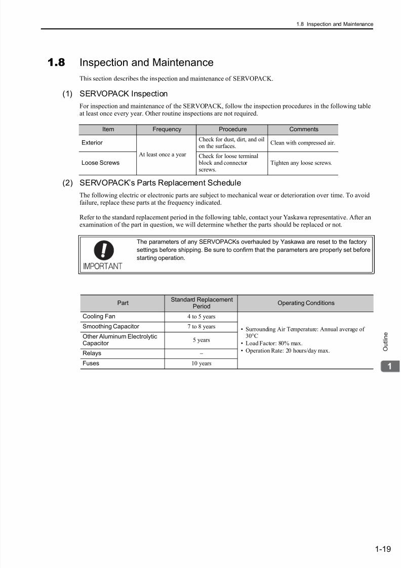
7/17/2019 Manual Yaskawa_servo_drive.pdf
http://slidepdf.com/reader/full/manual-yaskawaservodrivepdf 37/328
1.8 Inspection and Maintenance
1-19
O u t l i n e
1.8 Inspection and Maintenance
This section describes the inspection and maintenance of SERVOPACK.
(1) SERVOPACK Inspection
For inspection and maintenance of the SERVOPACK, follow the inspection procedures in the following tableat least once every year. Other routine inspections are not required.
(2) SERVOPACK’s Parts Replacement Schedule
The following electric or electronic parts are subject to mechanical wear or deterioration over time. To avoidfailure, replace these parts at the frequency indicated.
Refer to the standard replacement period in the following table, contact your Yaskawa representative. After anexamination of the part in question, we will determine whether the parts should be replaced or not.
Item Frequency Procedure Comments
Exterior
At least once a year
Check for dust, dirt, and oilon the surfaces.
Clean with compressed air.
Loose ScrewsCheck for loose terminal block and connectorscrews.
Tighten any loose screws.
The parameters of any SERVOPACKs overhauled by Yaskawa are reset to the factory
settings before shipping. Be sure to confirm that the parameters are properly set before
starting operation.
Part Standard ReplacementPeriod
Operating Conditions
Cooling Fan 4 to 5 years
• Surrounding Air Temperature: Annual average of30°C
• Load Factor: 80% max.
• Operation Rate: 20 hours/day max.
Smoothing Capacitor 7 to 8 years
Other Aluminum ElectrolyticCapacitor
5 years
Relays −
Fuses 10 years
7/17/2019 Manual Yaskawa_servo_drive.pdf
http://slidepdf.com/reader/full/manual-yaskawaservodrivepdf 38/3282-1
P a n e l D i s p l a y a n d O p e r a t i o n o f D i g i t a l O p e r a t o r
2
Panel Display and Operation of Digital Operator
2.1 Panel Display . . . . . . . . . . . . . . . . . . . . . . . . . . . . . . . . . . . . . . . . . . . . . .2-2
2.1.1 Status Display . . . . . . . . . . . . . . . . . . . . . . . . . . . . . . . . . . . . . . . . . . . . . . . . . . . . . . . 2-2
2.1.2 Alarm and Warning Display . . . . . . . . . . . . . . . . . . . . . . . . . . . . . . . . . . . . . . . . . . . . . 2-2
2.1.3 Hard Wire Base Block Display . . . . . . . . . . . . . . . . . . . . . . . . . . . . . . . . . . . . . . . . . . 2-2
2.1.4 Displays during Overtravel . . . . . . . . . . . . . . . . . . . . . . . . . . . . . . . . . . . . . . . . . . . . . 2-2
2.2 Utility Function Mode (Fn) . . . . . . . . . . . . . . . . . . . . . . . . . . . . . . . .2-3
2.3 Parameter (Pn) Operation . . . . . . . . . . . . . . . . . . . . . . . . . . . . . . . . 2-4
2.3.1 Parameter Classifications . . . . . . . . . . . . . . . . . . . . . . . . . . . . . . . . . . . . . . . . . . . . . . 2-4
2.3.2 Parameter Notation . . . . . . . . . . . . . . . . . . . . . . . . . . . . . . . . . . . . . . . . . . . . . . . . . . . 2-4
2.3.3 Parameter Setting Methods . . . . . . . . . . . . . . . . . . . . . . . . . . . . . . . . . . . . . . . . . . . . 2-5
2.4 Monitor Mode (Un) . . . . . . . . . . . . . . . . . . . . . . . . . . . . . . . . . . . . .2-7
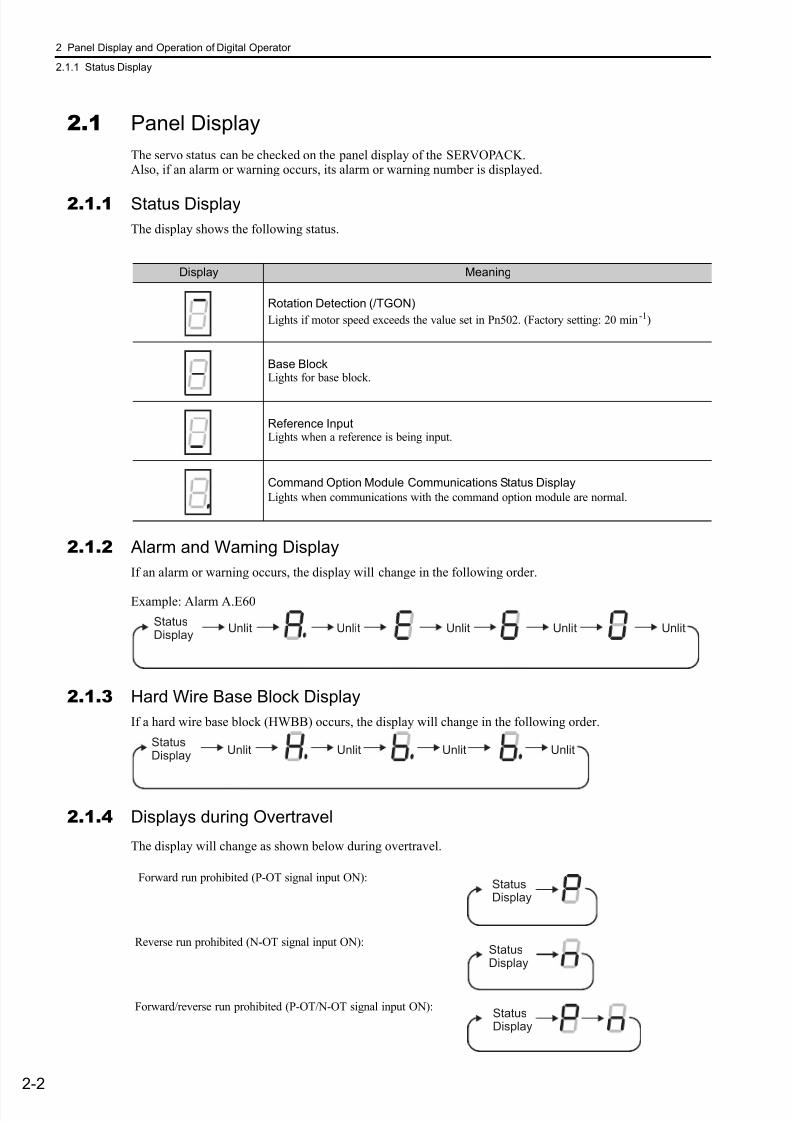
7/17/2019 Manual Yaskawa_servo_drive.pdf
http://slidepdf.com/reader/full/manual-yaskawaservodrivepdf 39/328
2 Panel Display and Operation of Digital Operator
2.1.1 Status Display
2-2
2.1 Panel Display
The servo status can be checked on the panel display of the SERVOPACK.Also, if an alarm or warning occurs, its alarm or warning number is displayed.
2.1.1 Status Display
The display shows the following status.
2.1.2 Alarm and Warning Display
If an alarm or warning occurs, the display will change in the following order.
Example: Alarm A.E60
2.1.3 Hard Wire Base Block Display
If a hard wire base block (HWBB) occurs, the display will change in the following order.
2.1.4 Displays during Overtravel
The display will change as shown below during overtravel.
Display Meaning
Rotation Detection (/TGON)
Lights if motor speed exceeds the value set in Pn502. (Factory setting: 20 min-1)
Base BlockLights for base block.
Reference InputLights when a reference is being input.
Command Option Module Communications Status Display
Lights when communications with the command option module are normal.
StatusDisplay
Unlit Unlit Unlit Unlit Unlit
StatusDisplay Unlit Unlit UnlitUnlit
Forward run prohibited (P-OT signal input ON):
Reverse run prohibited (N-OT signal input ON):
Forward/reverse run prohibited (P-OT/N-OT signal input ON):
StatusDisplay
StatusDisplay
StatusDisplay

7/17/2019 Manual Yaskawa_servo_drive.pdf
http://slidepdf.com/reader/full/manual-yaskawaservodrivepdf 40/328
2.2 Utility Function Mode (Fn)
2-3
P a n e l D i s p l a y a n d O p e r a t i o n o f D i g i t a l O p e r a t o r
2.2 Utility Function Mode (Fn)
The setup and adjustment functions of the SERVOPACK are executed in this mode.
The digital operator displays numbers beginning with Fn.
An operation example in Utility Function Mode is shown below for Origin Search (Fn003).
Step Display after Operation Keys Description
1Open the Utility Function Mode main menu and selectFn003.
2
Press the Key.
The display changes to the execution display of Fn003.
If the display does not change and “NO-OP” is dis-
played in the status display, change the following set-tings.
• If Write Prohibited is set in Fn010:→ Change the Write Prohibited setting.
• If a servo ON command has been entered:→Send a servo OFF command.
3
Press the Key.
“RUN” is displayed in the status display, and powerwill be applied to the servomotor.
If “NO-OP” is displayed, one of the following statuseswill be displayed:
• Main circuit power supply OFF
• Alarm
• Hard wire base block
4
Pressing the Key will rotate the motor in the for-
ward direction. Pressing the Key will rotate themotor in the reverse direction. The rotation of the ser-vomotor changes according to the setting of Pn000.0.
Note: Direction when viewed from the load of the ser-vomotor.
Press the or Key until the motor stops. If theorigin search completed normally, “-Complete-” is dis- played in the upper right corner.
5
When the origin search is completed, press theKey.
“BB” is displayed in the status display, and the servo-motor turns OFF. The display “-Complete-” changes to“-Z-Search-” in the upper right corner.
6
Press the Key.
The display returns to the Utility Function Mode mainmenu.This completes the operation.
: J O G
: Z – S e a r c h
: P r o g r a m J O G
: P r m I n i t
Parameter key
(Forward)
key
(Reverse)
Pn000n.0 CCW CW
n.1 CW CCW
: J O G
: Z – S e a r c h
: P r o g r a m J O G
: P r m I n i t
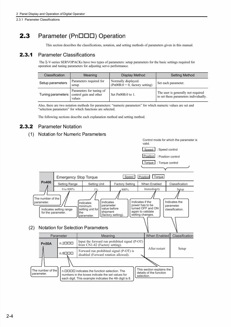
7/17/2019 Manual Yaskawa_servo_drive.pdf
http://slidepdf.com/reader/full/manual-yaskawaservodrivepdf 41/328
2 Panel Display and Operation of Digital Operator
2.3.1 Parameter Classifications
2-4
2.3 Parameter (Pn) Operation
This section describes the classifications, notation, and setting methods of parameters given in this manual.
2.3.1Parameter Classifications The Σ-V-series SERVOPACKs have two types of parameters: setup parameters for the basic settings required foroperation and tuning parameters for adjusting servo performance.
Also, there are two notation methods for parameters: “numeric parameters” for which numeric values are set and“selection parameters” for which functions are selected.
The following sections describe each explanation method and setting method.
2.3.2 Parameter Notation
(1) Notation for Numeric Parameters
Classification Meaning Display Method Setting Method
Setup parametersParameters required forsetup
Normally displayed.(Pn00B.0 = 0, factory setting)
Set each parameter.
Tuning parametersParameters for tuning ofcontrol gain and othervalues
Set Pn00B.0 to 1.The user is generally not requiredto set these parameters individually.
Pn406
1% 800%
Pn50A n.2
n.8
n. indicates the function selection. The
numbers in the boxes indicate the set values for
each digit. This example indicates the 4th digit is 8.
Emergency Stop Torque
Setting Range
0 to 800%
Setting Unit Factory Setting When Enabled
Setup
Classification
PositionSpeed Torque
Position
Torque
Control mode for which the parameter is
valid.
Speed : Speed control
: Position control
: Torque control
Indicates setting rangefor the parameter.
Parameter Meaning ClassificationWhen Enabled
Input the forward run prohibited signal (P-OT)from CN1-42 (Factory setting).
SetupAfter restartForward run prohibited signal (P-OT) isdisabled (Forward rotation allowed).
The number of theparameter.
Indicatesparametervalue beforeshipment(factory setting).
Indicatesminimumsetting unit fortheparameter.
Indicates if thepower has to beturned OFF and ONagain to validatesetting changes.
This section explains thedetails of the functionselection.
The number of the
parameter.
Immediately
Indicates the
parameter
classification.
(2) Notation for Selection Parameters
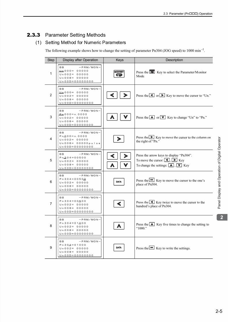
7/17/2019 Manual Yaskawa_servo_drive.pdf
http://slidepdf.com/reader/full/manual-yaskawaservodrivepdf 42/328
2.3 Parameter (Pn) Operation
2-5
P a n e l D i s p l a y a n d O p e r a t i o n o f D i g i t a l O p e r a t o r
2.3.3 Parameter Setting Methods
(1) Setting Method for Numeric Parameters
The following example shows how to change the setting of parameter Pn304 (JOG speed) to 1000 min-1.
Step Display after Operation Keys Description
1 Press the Key to select the Parameter/MonitorMode.
2 Press the or Key to move the cursor to “Un.”
3 Press the or Key to change “Un” to “Pn.”
4 Press the Key to move the cursor to the column onthe right of “Pn.”
5
Press the arrow keys to display “Pn304”.
To move the cursor: , Key
To change the settings: , Key
6 Press the Key to move the cursor to the one’s place of Pn304.
7 Press the Key twice to move the cursor to thehundred’s place of Pn304.
8 Press the Key five times to change the setting to“1000.”
9 Press the Key to write the settings.
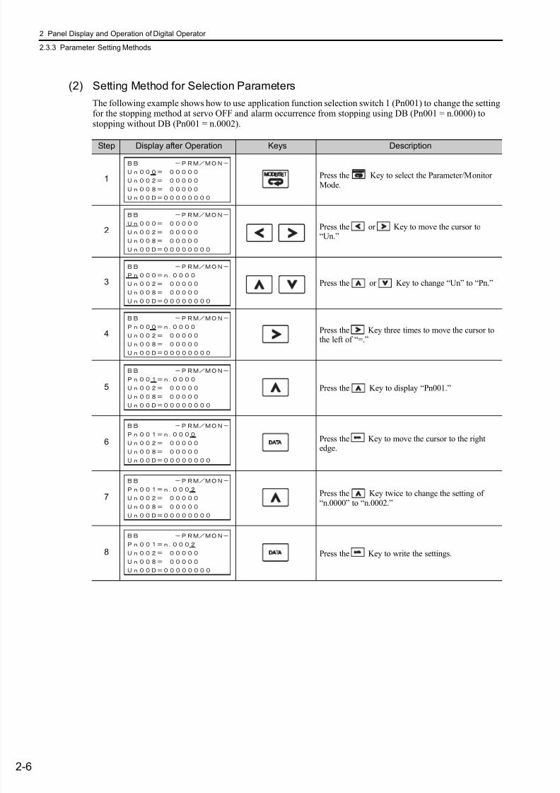
7/17/2019 Manual Yaskawa_servo_drive.pdf
http://slidepdf.com/reader/full/manual-yaskawaservodrivepdf 43/328
2 Panel Display and Operation of Digital Operator
2.3.3 Parameter Setting Methods
2-6
(2) Setting Method for Selection Parameters
The following example shows how to use application function selection switch 1 (Pn001) to change the settingfor the stopping method at servo OFF and alarm occurrence from stopping using DB (Pn001 = n.0000) tostopping without DB (Pn001 = n.0002).
Step Display after Operation Keys Description
1 Press the Key to select the Parameter/MonitorMode.
2 Press the or Key to move the cursor to“Un.”
3 Press the or Key to change “Un” to “Pn.”
4 Press the Key three times to move the cursor tothe left of “=.”
5 Press the Key to display “Pn001.”
6 Press the Key to move the cursor to the rightedge.
7 Press the Key twice to change the setting of“n.0000” to “n.0002.”
8 Press the Key to write the settings.

7/17/2019 Manual Yaskawa_servo_drive.pdf
http://slidepdf.com/reader/full/manual-yaskawaservodrivepdf 44/328
2.4 Monitor Mode (Un)
2-7
P a n e l D i s p l a y a n d O p e r a t i o n o f D i g i t a l O p e r a t o r
2.4 Monitor Mode (Un)
The monitor mode can be used for monitoring the reference values, I/O signal status, and SERVOPACK inter-nal status.
For details, refer to 7.2 Monitor Displays.
The digital operator display numbers begin with Un.
The following four Un numbers are displayed with the factory settings.
Shows the setting of Un000 (motor speed) as 0 min-1.
7/17/2019 Manual Yaskawa_servo_drive.pdf
http://slidepdf.com/reader/full/manual-yaskawaservodrivepdf 45/3283-1
W i r i n g a n d C o n n e c t i o n
3
Wiring and Connection
3.1 Main Circuit Wiring . . . . . . . . . . . . . . . . . . . . . . . . . . . . . . . . . . . . . . . . . .3-2
3.1.1 Main Circuit Terminals . . . . . . . . . . . . . . . . . . . . . . . . . . . . . . . . . . . . . . . . . . . . . . . . . 3-2
3.1.2 Using a Standard Power Supply Input
(Single-phase 100-V, Three-phase 200-V, or Three-phase 400-V) . . . . . . . . . . . . . . . 3-3
3.1.3 Using the SERVOPACK with Single-phase, 200-V Power Input . . . . . . . . . . . . . . . . 3-12
3.1.4 Using the SERVOPACK with a DC Power Input . . . . . . . . . . . . . . . . . . . . . . . . . . . . 3-15
3.1.5 Using More Than One SERVOPACK . . . . . . . . . . . . . . . . . . . . . . . . . . . . . . . . . . . . 3-17
3.1.6 General Precautions for Wiring . . . . . . . . . . . . . . . . . . . . . . . . . . . . . . . . . . . . . . . . . 3-18
3.2 I/O Signal Connections . . . . . . . . . . . . . . . . . . . . . . . . . . . . . . . . . . . . . .3-19
3.2.1 I/O Signal (CN1) Names and Functions . . . . . . . . . . . . . . . . . . . . . . . . . . . . . . . . . . 3-193.2.2 Safety Function Signal (CN8) Names and Functions . . . . . . . . . . . . . . . . . . . . . . . . 3-20
3.2.3 Example of I/O Signal Connections . . . . . . . . . . . . . . . . . . . . . . . . . . . . . . . . . . . . . 3-21
3.3 I/O Signal Allocations . . . . . . . . . . . . . . . . . . . . . . . . . . . . . . . . . . . . . . .3-22
3.3.1 Input Signal Allocations . . . . . . . . . . . . . . . . . . . . . . . . . . . . . . . . . . . . . . . . . . . . . . . 3-22
3.3.2 Output Signal Allocation . . . . . . . . . . . . . . . . . . . . . . . . . . . . . . . . . . . . . . . . . . . . . . 3-24
3.4 Connection to Host Controller . . . . . . . . . . . . . . . . . . . . . . . . . . . . . . . . .3-25
3.4.1 Sequence Input Circuits . . . . . . . . . . . . . . . . . . . . . . . . . . . . . . . . . . . . . . . . . . . . . . 3-25
3.4.2 Sequence Output Circuits . . . . . . . . . . . . . . . . . . . . . . . . . . . . . . . . . . . . . . . . . . . . . 3-27
3.5 Wiring Communications Using Command Option Modules . . . . . . . . . .3-29
3.6 Encoder Connections . . . . . . . . . . . . . . . . . . . . . . . . . . . . . . . . . . . . . . .3-303.6.1 Encoder Signal (CN2) Names and Functions . . . . . . . . . . . . . . . . . . . . . . . . . . . . . . 3-30
3.6.2 Examples of Encoder Connection . . . . . . . . . . . . . . . . . . . . . . . . . . . . . . . . . . . . . . . 3-30
3.7 Regenerative Resistors Connections . . . . . . . . . . . . . . . . . . . . . . . . . . .3-32
3.7.1 Connecting Regenerative Resistors . . . . . . . . . . . . . . . . . . . . . . . . . . . . . . . . . . . . . 3-32
3.7.2 Setting Regenerative Resistor Capacity . . . . . . . . . . . . . . . . . . . . . . . . . . . . . . . . . . 3-34
3.8 Noise Control and Measures for Harmonic Suppression . . . . . . . . . . . .3-35
3.8.1 Wiring for Noise Control . . . . . . . . . . . . . . . . . . . . . . . . . . . . . . . . . . . . . . . . . . . . . . 3-35
3.8.2 Precautions on Connecting Noise Filter . . . . . . . . . . . . . . . . . . . . . . . . . . . . . . . . . . 3-37
3.8.3 Connecting AC/DC Reactor for Harmonic Suppression . . . . . . . . . . . . . . . . . . . . . . 3-39
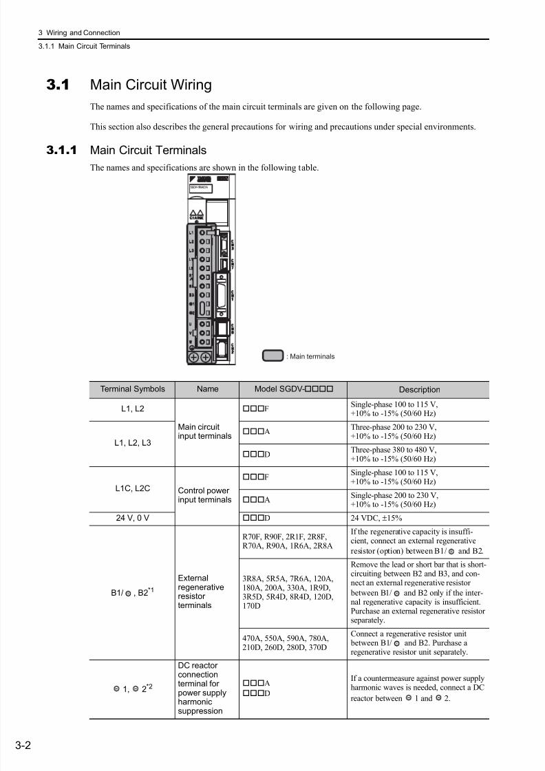
7/17/2019 Manual Yaskawa_servo_drive.pdf
http://slidepdf.com/reader/full/manual-yaskawaservodrivepdf 46/328
3 Wiring and Connection
3.1.1 Main Circuit Terminals
3-2
3.1 Main Circuit Wiring
The names and specifications of the main circuit terminals are given on the following page.
This section also describes the general precautions for wiring and precautions under special environments.
3.1.1 Main Circuit Terminals
The names and specifications are shown in the following table.
: Main terminals
SGDV-1R6AE1A
Terminal Symbols Name Model SGDV- Description
L1, L2
Main circuitinput terminals
F Single-phase 100 to 115 V,+10% to -15% (50/60 Hz)
L1, L2, L3
AThree-phase 200 to 230 V,+10% to -15% (50/60 Hz)
DThree-phase 380 to 480 V,+10% to -15% (50/60 Hz)
L1C, L2C Control powerinput terminals
FSingle-phase 100 to 115 V,+10% to -15% (50/60 Hz)
ASingle-phase 200 to 230 V,+10% to -15% (50/60 Hz)
24 V, 0 V D 24 VDC, ±15%
B1/ , B2*1
Externalregenerativeresistorterminals
R70F, R90F, 2R1F, 2R8F,R70A, R90A, 1R6A, 2R8A
If the regenerative capacity is insuffi-
cient, connect an external regenerativeresistor (option) between B1/ and B2.
3R8A, 5R5A, 7R6A, 120A,180A, 200A, 330A, 1R9D,3R5D, 5R4D, 8R4D, 120D,170D
Remove the lead or short bar that is short-circuiting between B2 and B3, and con-nect an external regenerative resistor
between B1/ and B2 only if the inter-nal regenerative capacity is insufficient.Purchase an external regenerative resistorseparately.
470A, 550A, 590A, 780A,210D, 260D, 280D, 370D
Connect a regenerative resistor unit between B1/ and B2. Purchase aregenerative resistor unit separately.
1, 2*2
DC reactor
connectionterminal forpower supplyharmonicsuppression
A
D
If a countermeasure against power supplyharmonic waves is needed, connect a DC
reactor between 1 and 2.
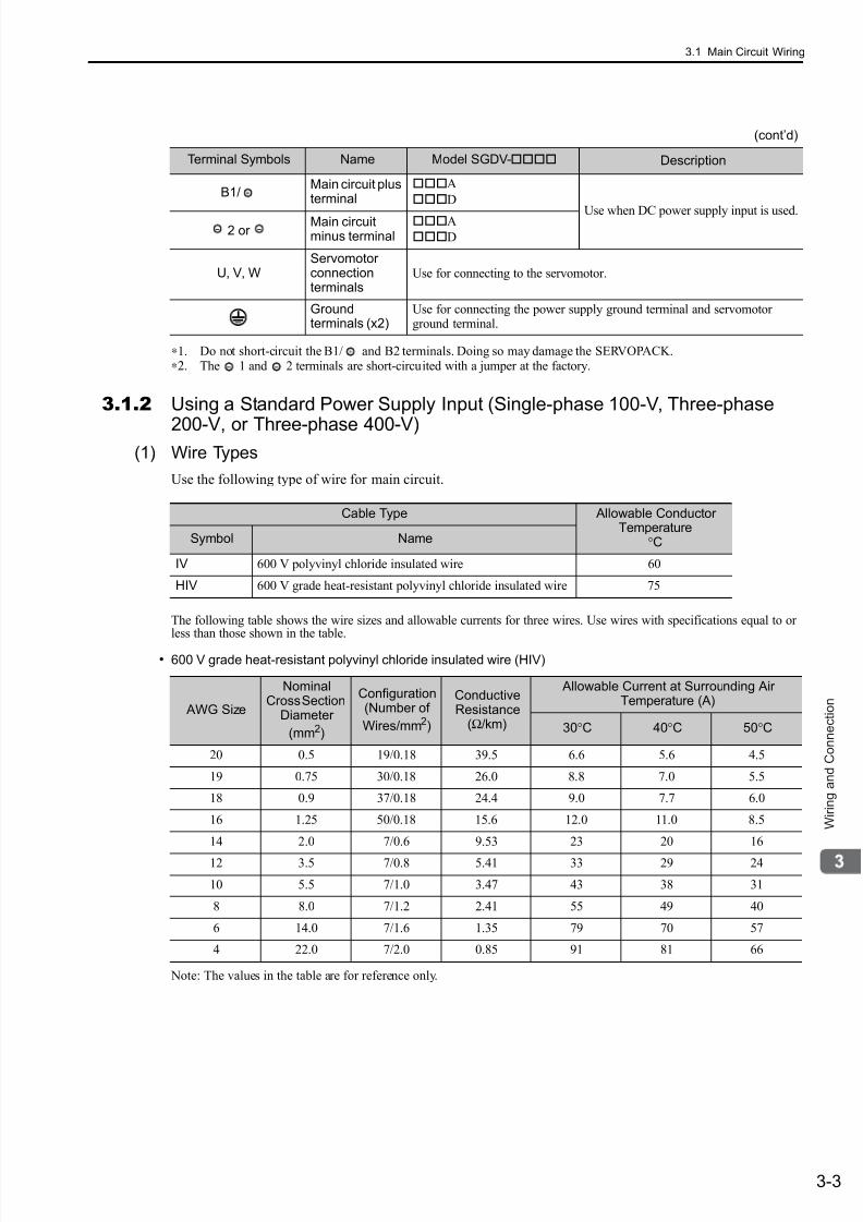
7/17/2019 Manual Yaskawa_servo_drive.pdf
http://slidepdf.com/reader/full/manual-yaskawaservodrivepdf 47/328
3.1 Main Circuit Wiring
3-3
W i r i n g a n d C o n n e c t i o n
∗1. Do not short-circuit the B1/ and B2 terminals. Doing so may damage the SERVOPACK.∗2. The 1 and 2 terminals are short-circuited with a jumper at the factory.
3.1.2 Using a Standard Power Supply Input (Single-phase 100-V, Three-phase
200-V, or Three-phase 400-V)(1) Wire Types
Use the following type of wire for main circuit.
The following table shows the wire sizes and allowable currents for three wires. Use wires with specifications equal to orless than those shown in the table.
• 600 V grade heat-resistant polyvinyl chloride insulated wire (HIV)
Note: The values in the table are for reference only.
B1/Main circuit plusterminal
A
D
Use when DC power supply input is used. 2 or
Main circuitminus terminal
A
D
U, V, WServomotorconnectionterminals
Use for connecting to the servomotor.
Groundterminals (x2)
Use for connecting the power supply ground terminal and servomotorground terminal.
(cont’d)
Terminal Symbols Name Model SGDV- Description
Cable Type Allowable ConductorTemperature
°CSymbol Name
IV 600 V polyvinyl chloride insulated wire 60
HIV 600 V grade heat-resistant polyvinyl chloride insulated wire 75
AWG Size
NominalCross Section
Diameter
(mm2)
Configuration(Number of
Wires/mm2)
ConductiveResistance
(Ω/km)
Allowable Current at Surrounding AirTemperature (A)
30°C 40°C 50°C
20 0.5 19/0.18 39.5 6.6 5.6 4.5
19 0.75 30/0.18 26.0 8.8 7.0 5.5
18 0.9 37/0.18 24.4 9.0 7.7 6.0
16 1.25 50/0.18 15.6 12.0 11.0 8.5
14 2.0 7/0.6 9.53 23 20 16
12 3.5 7/0.8 5.41 33 29 24
10 5.5 7/1.0 3.47 43 38 31
8 8.0 7/1.2 2.41 55 49 40
6 14.0 7/1.6 1.35 79 70 57
4 22.0 7/2.0 0.85 91 81 66
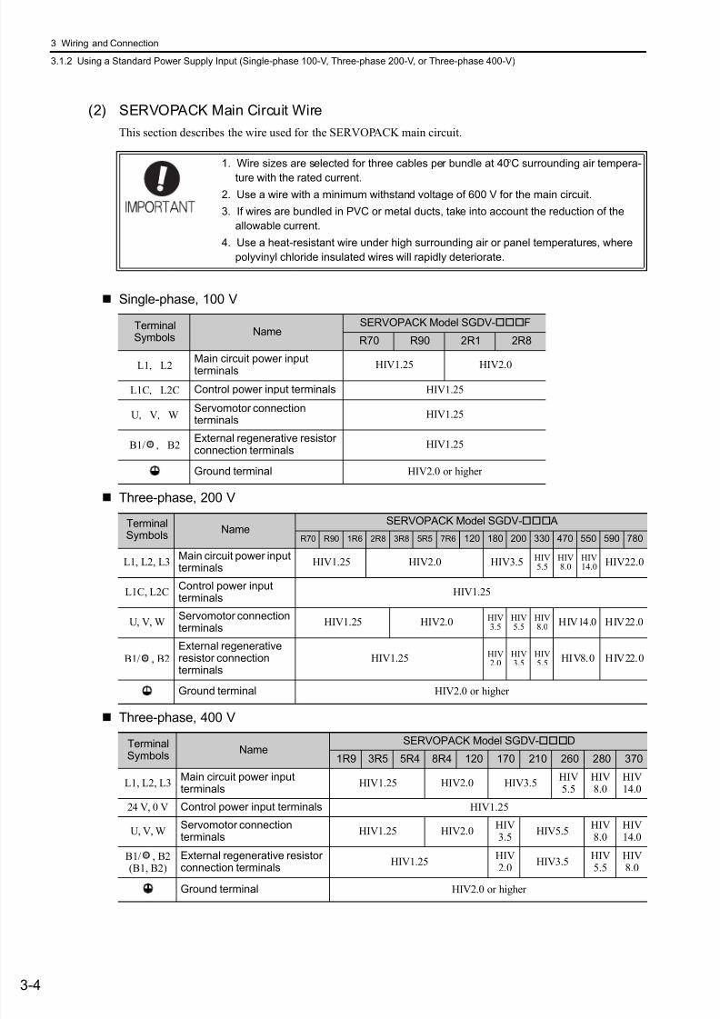
7/17/2019 Manual Yaskawa_servo_drive.pdf
http://slidepdf.com/reader/full/manual-yaskawaservodrivepdf 48/328
3 Wiring and Connection
3.1.2 Using a Standard Power Supply Input (Single-phase 100-V, Three-phase 200-V, or Three-phase 400-V)
3-4
(2) SERVOPACK Main Circuit Wire
This section describes the wire used for the SERVOPACK main circuit.
Single-phase, 100 V
Three-phase, 200 V
Three-phase, 400 V
1. Wire sizes are selected for three cables per bundle at 40°C surrounding air tempera-
ture with the rated current.2. Use a wire with a minimum withstand voltage of 600 V for the main circuit.
3. If wires are bundled in PVC or metal ducts, take into account the reduction of the
allowable current.
4. Use a heat-resistant wire under high surrounding air or panel temperatures, where
polyvinyl chloride insulated wires will rapidly deteriorate.
TerminalSymbols
NameSERVOPACK Model SGDV-F
R70 R90 2R1 2R8
L1,L2 Main circuit power inputterminals
HIV1.25 HIV2.0
L1C,L2C Control power input terminals HIV1.25
U,V,WServomotor connectionterminals
HIV1.25
B1/ ,B2External regenerative resistorconnection terminals
HIV1.25
Ground terminal HIV2.0 or higher
Terminal
SymbolsName
SERVOPACK Model SGDV- A
R70 R90 1R6 2R8 3R8 5R5 7R6 120 180 200 330 470 550 590 780
L1, L2, L3Main circuit power inputterminals
HIV1.25 HIV2.0 HIV3.5 HIV5.5
HIV8.0
HIV14.0
HIV22.0
L1C, L2CControl power inputterminals
HIV1.25
U, V, WServomotor connectionterminals
HIV1.25 HIV2.0 HIV3.5
HIV5.5
HIV8.0
HIV14.0 HIV22.0
B1/ , B2
External regenerativeresistor connectionterminals
HIV1.25 HIV2.0
HIV3.5
HIV5.5
HIV8.0 HIV22.0
Ground terminal HIV2.0 or higher
TerminalSymbols
NameSERVOPACK Model SGDV-D
1R9 3R5 5R4 8R4 120 170 210 260 280 370
L1, L2, L3Main circuit power inputterminals
HIV1.25 HIV2.0 HIV3.5HIV5.5
HIV8.0
HIV14.0
24 V, 0 V Control power input terminals HIV1.25
U, V, WServomotor connectionterminals
HIV1.25 HIV2.0HIV3.5
HIV5.5HIV8.0
HIV14.0
B1/ , B2(B1, B2)
External regenerative resistorconnection terminals
HIV1.25HIV2.0
HIV3.5HIV5.5
HIV8.0
Ground terminal HIV2.0 or higher
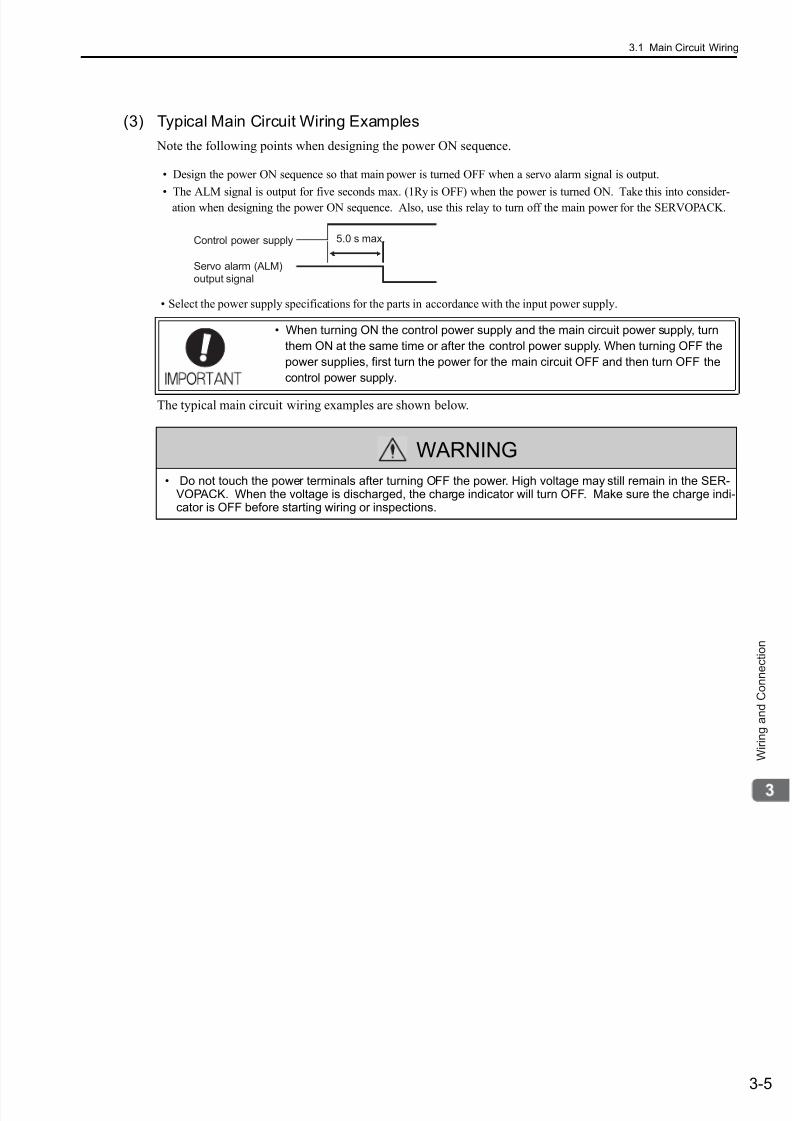
7/17/2019 Manual Yaskawa_servo_drive.pdf
http://slidepdf.com/reader/full/manual-yaskawaservodrivepdf 49/328
3.1 Main Circuit Wiring
3-5
W i r i n g a n d C o n n e c t i o n
(3) Typical Main Circuit Wiring Examples
Note the following points when designing the power ON sequence.
• Design the power ON sequence so that main power is turned OFF when a servo alarm signal is output.
• The ALM signal is output for five seconds max. (1Ry is OFF) when the power is turned ON. Take this into consider-ation when designing the power ON sequence. Also, use this relay to turn off the main power for the SERVOPACK.
• Select the power supply specifications for the parts in accordance with the input power supply.
The typical main circuit wiring examples are shown below.
• When turning ON the control power supply and the main circuit power supply, turn
them ON at the same time or after the control power supply. When turning OFF the
power supplies, first turn the power for the main circuit OFF and then turn OFF the
control power supply.
WARNING
• Do not touch the power terminals after turning OFF the power. High voltage may still remain in the SER-VOPACK. When the voltage is discharged, the charge indicator will turn OFF. Make sure the charge indi-cator is OFF before starting wiring or inspections.
Control power supply
Servo alarm (ALM)output signal
5.0 s max.
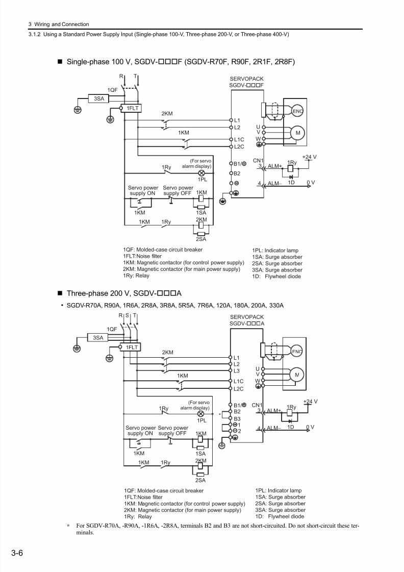
7/17/2019 Manual Yaskawa_servo_drive.pdf
http://slidepdf.com/reader/full/manual-yaskawaservodrivepdf 50/328
3 Wiring and Connection
3.1.2 Using a Standard Power Supply Input (Single-phase 100-V, Three-phase 200-V, or Three-phase 400-V)
3-6
Single-phase 100 V, SGDV-F (SGDV-R70F, R90F, 2R1F, 2R8F)
Three-phase 200 V, SGDV- A
• SGDV-R70A, R90A, 1R6A, 2R8A, 3R8A, 5R5A, 7R6A, 120A, 180A, 200A, 330A
∗ For SGDV-R70A, -R90A, -1R6A, -2R8A, terminals B2 and B3 are not short-circuited. Do not short-circuit these ter-minals.
L1
ENC
UV
WM
0 V
1Ry ALM+
ALM−
3
4 1D
2KM
1KM
B2
L2
CN1
1QF
R T
1FLT
+24 V
B1/
3SA
1Ry
1PL
1KM
2KM
1SA1KM
1Ry1KM
2SA
L1C
L2C
1PL: Indicator lamp
1SA: Surge absorber
2SA: Surge absorber
3SA: Surge absorber
1D: Flywheel diode
1QF: Molded-case circuit breaker
1FLT: Noise filter
1KM: Magnetic contactor (for control power supply)
2KM: Magnetic contactor (for main power supply)
1Ry: Relay
SERVOPACK
SGDV-F
(For servoalarm display)
supply ONServo power
supply OFFServo power
2KML1
ENC
UV
WM
0 V
1Ry ALM+
ALM−
3
4 1D
B2
B3
L2
CN1
1KML1C
L3
L2C
1QF
R S T
1FLT
+24 V
12
3SA
*
B1/1Ry
1PL
1KM
2KM
1SA
1Ry1KM
2SA
1KM
1PL: Indicator lamp
1SA: Surge absorber
2SA: Surge absorber
3SA: Surge absorber
1D: Flywheel diode
1QF: Molded-case circuit breaker
1FLT: Noise filter
1KM: Magnetic contactor (for control power supply)
2KM: Magnetic contactor (for main power supply)
1Ry: Relay
SERVOPACK
SGDV- A
(For servoalarm display)
supply ONServo power
supply OFFServo power
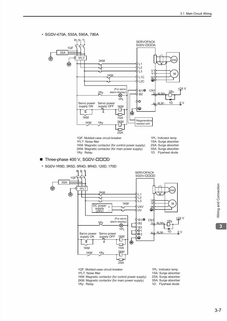
7/17/2019 Manual Yaskawa_servo_drive.pdf
http://slidepdf.com/reader/full/manual-yaskawaservodrivepdf 51/328
3.1 Main Circuit Wiring
3-7
W i r i n g a n d C o n n e c t i o n
• SGDV-470A, 550A, 590A, 780A
Three-phase 400 V, SGDV-D
• SGDV-1R9D, 3R5D, 5R4D, 8R4D, 120D, 170D
2KML1
ENC
UV
WM
0 V
1Ry ALM+
ALM−
3
4 1D
B2
L2
CN1
1KML1C
L3
L2C
1QF
R S T
1FLT
+24 V
3SA
B1/1Ry
1PL
1KM
2KM
1SA
1Ry1KM
2SA
1KM
SGDV- A
Regenerativeresistor unit
(For servoalarm display)
supply ONServo power
supply OFFServo power
SERVOPACK
1QF: Molded-case circuit breaker
1FLT: Noise filter
1KM: Magnetic contactor (for control power supply)
2KM: Magnetic contactor (for main power supply)
1Ry: Relay
1PL: Indicator lamp
1SA: Surge absorber
2SA: Surge absorber
3SA: Surge absorber
1D: Flywheel diode
ENC
UV
WM
0 V
1Ry ALM+
ALM−
3
4 1D
CN1
1QF
R S T
1FLT
+24 V
3SA
B2
B312
B1/1Ry
1PL
1KM
2KM
1SA
1Ry1KM
2SA
L12KM
L2L3
24V+−
1KM
0V
1KM
1QF: Molded-case circuit breaker
1FLT: Noise filter
1KM: Magnetic contactor (for control power supply)
2KM: Magnetic contactor (for main power supply)1Ry: Relay
1PL: Indicator lamp
1SA: Surge absorber
2SA: Surge absorber
3SA: Surge absorber 1D: Flywheel diode
SGDV-D
DC power supply(24V)
(For servoalarm display)
supply ONServo power
supply OFFServo power
SERVOPACK

7/17/2019 Manual Yaskawa_servo_drive.pdf
http://slidepdf.com/reader/full/manual-yaskawaservodrivepdf 52/328
3 Wiring and Connection
3.1.2 Using a Standard Power Supply Input (Single-phase 100-V, Three-phase 200-V, or Three-phase 400-V)
3-8
• SGDV-210D, 260D, 280D, 370D
ENC
UVW
M
0 V
1Ry ALM+
ALM−
3
4 1D
CN1
1QF
R S T
1FLT
+24 V
3SA
B2
12
B1/1Ry
1PL
1KM
2KM
1SA
1Ry1KM
2SA
L12KM
L2L3
24V+−
1KM
0V
1KM
SGDV-D
DC powersupply(24 V)
Regenerativeresistor unit
(For servoalarm display)
supply ONServo power
supply OFFServo power
SERVOPACK
1QF: Molded-case circuit breaker
1FLT: Noise filter
1KM: Magnetic contactor (for control power supply)
2KM: Magnetic contactor (for main power supply)
1Ry: Relay
1PL: Indicator lamp
1SA: Surge absorber
2SA: Surge absorber
3SA: Surge absorber
1D: Flywheel diode

7/17/2019 Manual Yaskawa_servo_drive.pdf
http://slidepdf.com/reader/full/manual-yaskawaservodrivepdf 53/328
3.1 Main Circuit Wiring
3-9
W i r i n g a n d C o n n e c t i o n
(4) Power Supply Capacities and Power Losses
The following table gives the power capacities and power losses of the SERVOPACK.
∗1. For the optional JUSP-RA04-E regenerative resistor unit.∗2. For the optional JUSP-RA05-E regenerative resistor unit.∗3. For the optional JUSP-RA18-E regenerative resistor unit∗4. For the optional JUSP-RA19-E regenerative resistor unit. Note 1. SGDV-R70F, -R90F, -2R1F, -2R8F, -R70A, -R90A, -1R6A, and -2R8A SERVOPACKs do not have built-in
regenerative resistors. If the regenerative energy exceeds the specified value, connect an external regenerativeresistor (optional).
2. SGDV-470A, -550A, -590A, -780A, -210D, -260D, -280D, -370D SERVOPACKs do not have built-in regenera-tive resistors. Be sure to connect a regenerative resistor unit (optional) or an external regenerative resistor(optional). For selection details, refer to 3.7 Regenerative Resistors Connections.
3. Regenerative resistor power losses are allowable losses. Take the following action if the actual power loss
exceeds the allowable power loss.
• Remove the lead or short bar that is short-circuiting the SERVOPACK main circuit terminal B2 and B3.(SGDV-3R8A, -5R5A, -7R6A, -120A, -180A, -200A, -330A, or 400-V class SERVOPACKs.)
• Install an external regenerative resistor (optional). For selection details, refer to 3.7 Regenerative ResistorsConnections.
Main CircuitPowerSupply
Maximum
ApplicableMotorCapacity
[kW]
SERVO-
PACKModelSGDV-
Power Sup-
ply Capacityper SERVO-PACK[kVA]
OutputCurrent[Arms]
Main
CircuitPowerLoss[W]
Regener-
ativeResistorPower
Loss [W]
Control
CircuitPowerLoss[W]
Total
PowerLoss[W]
Single-phase,100-V
0.05 R70F 0.2 0.66 5.4
– 17
22.4
0.1 R90F 0.3 0.91 7.8 24.8
0.2 2R1F 0.7 2.1 14.4 31.4
0.4 2R8F 1.4 2.8 25.6 42.6
Three-phase,200-V
0.05 R70A 0.2 0.66 5.1
–
17
22.1
0.1 R90A 0.3 0.91 7.3 24.3
0.2 1R6A 0.6 1.6 13.5 30.5
0.4 2R8A 1 2.8 24.0 41.00.5 3R8A 1.4 3.8 20.1
8
45.1
0.75 5R5A 1.6 5.5 43.8 68.8
1.0 7R6A 2.3 7.6 53.6 78.6
1.5 120A 3.2 11.6 65.8 10
22
97.8
2.0 180A 4 18.5 111.916
149.9
3.0 200A 5.9 19.6 113.8 161.4
5.0 330A 7.5 32.9 263.7 36 27 326.7
6.0 470A 10.7 46.9 279.4 (180) *1
33312.4
7.5 550A 14.6 54.7 357.8
(350) *2
390.8
11 590A 21.7 58.6 431.748
479.7
15 780A 29.6 78 599.0 647.0
Three-phase,400-V
0.5 1R9D 1.1 1.9 24.6
14 21
59.6
1.0 3R5D 2.3 3.5 46.1 81.1
1.5 5R4D 3.5 5.4 71.3 106.3
2.0 8R4D 4.5 8.4 77.928 25
130.9
3.0 120D 7.1 11.9 108.7 161.7
5.0 170D 11.7 16.5 161.1 36 24 221.1
6.0 210D 12.4 20.8 172.7(180) *3 27
199.7
7.5 260D 14.4 25.7 218.6 245.6
11 280D 21.9 28.1 294.6(350) *4 30
324.6
15 370D 30.6 37.2 403.8 433.8
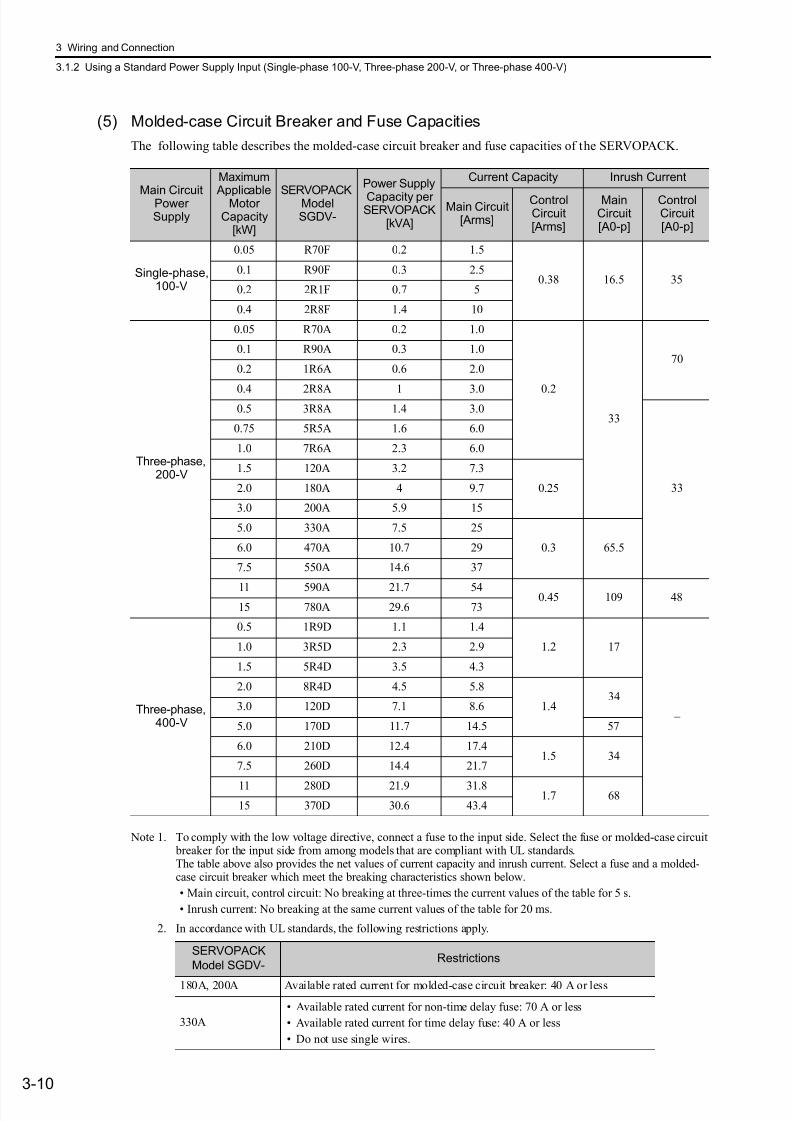
7/17/2019 Manual Yaskawa_servo_drive.pdf
http://slidepdf.com/reader/full/manual-yaskawaservodrivepdf 54/328
3 Wiring and Connection
3.1.2 Using a Standard Power Supply Input (Single-phase 100-V, Three-phase 200-V, or Three-phase 400-V)
3-10
(5) Molded-case Circuit Breaker and Fuse Capacities
The following table describes the molded-case circuit breaker and fuse capacities of the SERVOPACK.
Note 1. To comply with the low voltage directive, connect a fuse to the input side. Select the fuse or molded-case circuit breaker for the input side from among models that are compliant with UL standards.The table above also provides the net values of current capacity and inrush current. Select a fuse and a molded-case circuit breaker which meet the breaking characteristics shown below.
• Main circuit, control circuit: No breaking at three-times the current values of the table for 5 s.
• Inrush current: No breaking at the same current values of the table for 20 ms.
2. In accordance with UL standards, the following restrictions apply.
Main CircuitPowerSupply
Maximum
ApplicableMotorCapacity
[kW]
SERVOPACKModelSGDV-
Power Supply
Capacity perSERVOPACK
[kVA]
Current Capacity Inrush Current
Main Circuit[Arms]
ControlCircuit[Arms]
MainCircuit[A0-p]
ControlCircuit[A0-p]
Single-phase,100-V
0.05 R70F 0.2 1.5
0.38 16.5 350.1 R90F 0.3 2.5
0.2 2R1F 0.7 5
0.4 2R8F 1.4 10
Three-phase,200-V
0.05 R70A 0.2 1.0
0.2
33
700.1 R90A 0.3 1.0
0.2 1R6A 0.6 2.0
0.4 2R8A 1 3.00.5 3R8A 1.4 3.0
33
0.75 5R5A 1.6 6.0
1.0 7R6A 2.3 6.0
1.5 120A 3.2 7.3
0.252.0 180A 4 9.7
3.0 200A 5.9 15
5.0 330A 7.5 25
0.3 65.56.0 470A 10.7 29
7.5 550A 14.6 37
11 590A 21.7 54 0.45 109 4815 780A 29.6 73
Three-phase,400-V
0.5 1R9D 1.1 1.4
1.2 17
–
1.0 3R5D 2.3 2.9
1.5 5R4D 3.5 4.3
2.0 8R4D 4.5 5.8
1.434
3.0 120D 7.1 8.6
5.0 170D 11.7 14.5 57
6.0 210D 12.4 17.41.5 34
7.5 260D 14.4 21.7
11 280D 21.9 31.8 1.7 6815 370D 30.6 43.4
SERVOPACK
Model SGDV-Restrictions
180A, 200A Available rated current for molded-case circuit breaker: 40 A or less
330A
• Available rated current for non-time delay fuse: 70 A or less
• Available rated current for time delay fuse: 40 A or less
• Do not use single wires.
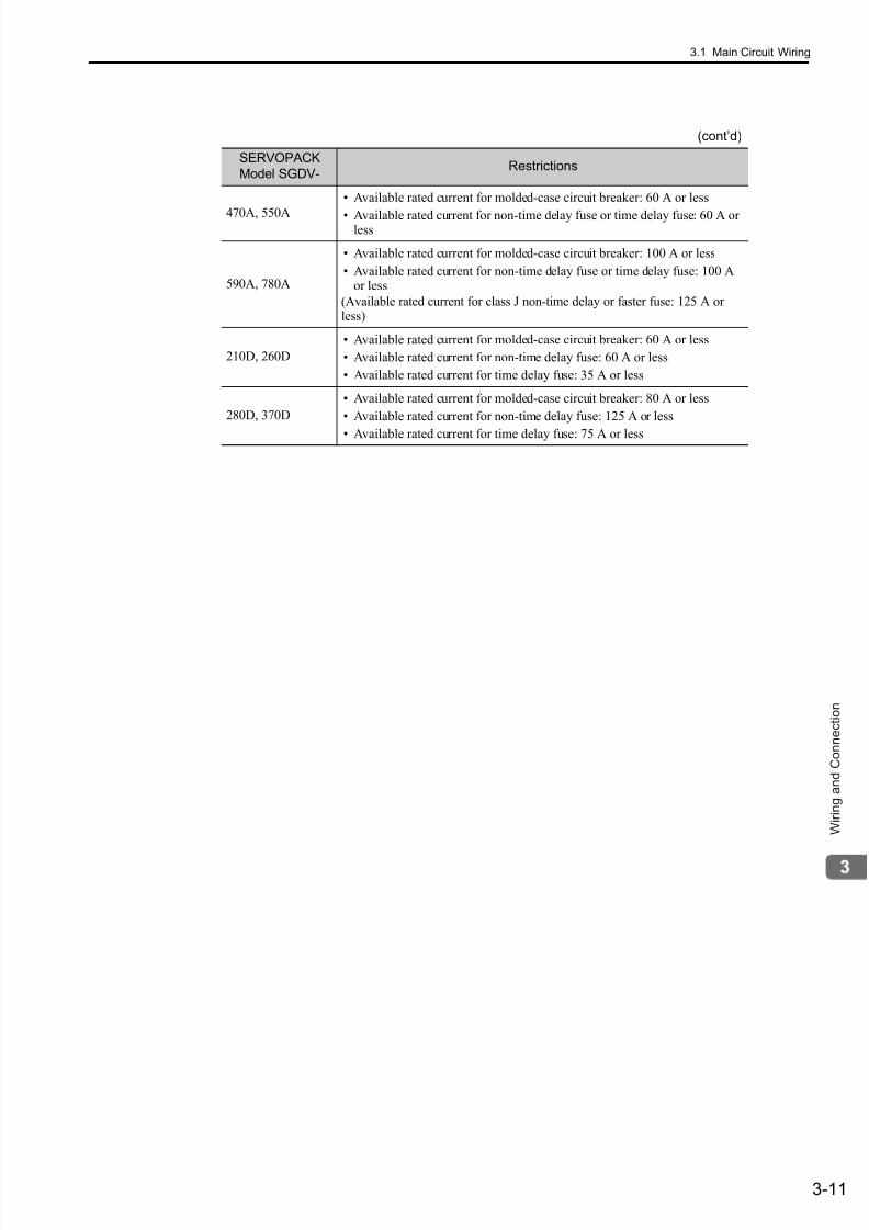
7/17/2019 Manual Yaskawa_servo_drive.pdf
http://slidepdf.com/reader/full/manual-yaskawaservodrivepdf 55/328
3.1 Main Circuit Wiring
3-11
W i r i n g a n d C o n n e c t i o n
470A, 550A
• Available rated current for molded-case circuit breaker: 60 A or less
• Available rated current for non-time delay fuse or time delay fuse: 60 A orless
590A, 780A
• Available rated current for molded-case circuit breaker: 100 A or less
• Available rated current for non-time delay fuse or time delay fuse: 100 Aor less
(Available rated current for class J non-time delay or faster fuse: 125 A orless)
210D, 260D
• Available rated current for molded-case circuit breaker: 60 A or less
• Available rated current for non-time delay fuse: 60 A or less
• Available rated current for time delay fuse: 35 A or less
280D, 370D
• Available rated current for molded-case circuit breaker: 80 A or less
• Available rated current for non-time delay fuse: 125 A or less
• Available rated current for time delay fuse: 75 A or less
(cont’d)
SERVOPACK
Model SGDV-Restrictions
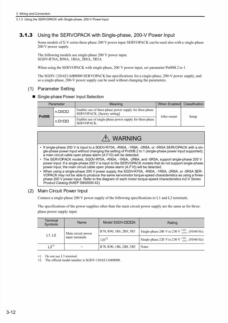
7/17/2019 Manual Yaskawa_servo_drive.pdf
http://slidepdf.com/reader/full/manual-yaskawaservodrivepdf 56/328
3 Wiring and Connection
3.1.3 Using the SERVOPACK with Single-phase, 200-V Power Input
3-12
3.1.3 Using the SERVOPACK with Single-phase, 200-V Power Input
Some models of Σ-V series three-phase 200 V power input SERVOPACK can be used also with a single-phase200 V power supply.
The following models use single-phase 200 V power input.SGDV-R70A, R90A, 1R6A, 2R8A, 5R5A
When using the SERVOPACK with single-phase, 200 V power input, set parameter Pn00B.2 to 1.
The SGDV-120AE1A008000 SERVOPACK has specifications for a single-phase, 200-V power supply, andso a single-phase, 200-V power supply can be used without changing the parameters.
(1) Parameter Setting
Single-phase Power Input Selection
(2) Main Circuit Power Input
Connect a single-phase 200 V power supply of the following specifications to L1 and L2 terminals.
The specifications of the power supplies other than the main circuit power supply are the same as for three-
phase power supply input.
∗1. Do not use L3 terminal.∗2. The official model number is SGDV-120AE1A008000.
Parameter Meaning When Enabled Classification
Pn00Bn.
0
Enables use of three-phase power supply for three-phase
SERVOPACK. [factory setting]After restart Setup
n.1Enables use of single-phase power supply for three-phaseSERVOPACK.
WARNING
• If single-phase 200 V is input to a SGDV-R70A, -R90A, -1R6A, -2R8A, or -5R5A SERVOPACK with a sin-gle-phase power input without changing the setting of Pn00B.2 to 1 (single-phase power input supported),a main circuit cable open phase alarm (A.F10) will be detected.
• The SERVOPACK models, SGDV-R70A, -R90A, -1R6A, -2R8A, and -5R5A, support single-phase 200 Vpower input. If a single-phase 200 V is input to the SERVOPACK models that do not support single-phasepower input, the main circuit cable open phase alarm (A.F10) will be detected.
• When using a single-phase 200 V power supply, the SGDV-R70A, -R90A, -1R6A, -2R8A, or -5R5A SER-VOPACK may not be able to produce the same servomotor torque-speed characteristics as using a three-phase 200 V power input. Refer to the diagram of each motor torque-speed characteristics in Σ -V SeriesProduct Catalog (KAEP S800000 42).
TerminalSymbols
Name Model SGDV- A Rating
L1, L2Main circuit powerinput terminals
R70, R90, 1R6, 2R8, 5R5 Single-phase 200 V to 230 V , (50/60 Hz)
120*2 Single-phase 220 V to 230 V , (50/60 Hz)
L3*1 – R70, R90, 1R6, 2R8, 5R5 None
+10%
−15%
+10%
−15%
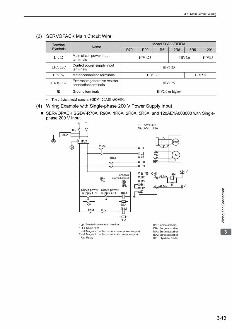
7/17/2019 Manual Yaskawa_servo_drive.pdf
http://slidepdf.com/reader/full/manual-yaskawaservodrivepdf 57/328
3.1 Main Circuit Wiring
3-13
W i r i n g a n d C o n n e c t i o n
(3) SERVOPACK Main Circuit Wire
∗ The official model name is SGDV-120AE1A008000.
(4) Wiring Example with Single-phase 200 V Power Supply Input
SERVOPACK SGDV-R70A, R90A, 1R6A, 2R8A, 5R5A, and 120AE1A008000 with Single-phase 200 V Input
TerminalSymbols
NameModel SGDV- A
R70 R90 1R6 2R8 5R5 120*
L1, L2Main circuit power inputterminals HIV1.25 HIV2.0 HIV3.5
L1C, L2CControl power supply inputterminals
HIV1.25
U, V, W Motor connection terminals HIV1.25 HIV2.0
B1/ , B2External regenerative resistorconnection terminals
HIV1.25
Ground terminals HIV2.0 or higher
1KM
1Ry
1PL
1KM
2KM
1SA
1Ry1KM
2SA
L1
ENC
UV
WM
0 V
1Ry ALM+
ALM−
3
4 1D
2KM
L3
B2
B3
L2
CN1
1QF
R T
1FLT
+24 V
12
L1C
1KM
L2C
3SA
B1/
1PL
1SA
2SA3SA
1D:
: Indicator lamp
: Surge absorber
: Surge absorber : Surge absorber
Flywheel diode
1QF
1FLT
1KM
: Molded-case circuit breaker
: Noise filter
: Magnetic contactor (for control power supply)2KM: Magnetic contactor (for main power supply)
1Ry: Relay
SERVOPACKSGDV- A
(For servoalarm display)
supply ONServo power
supply OFFServo power
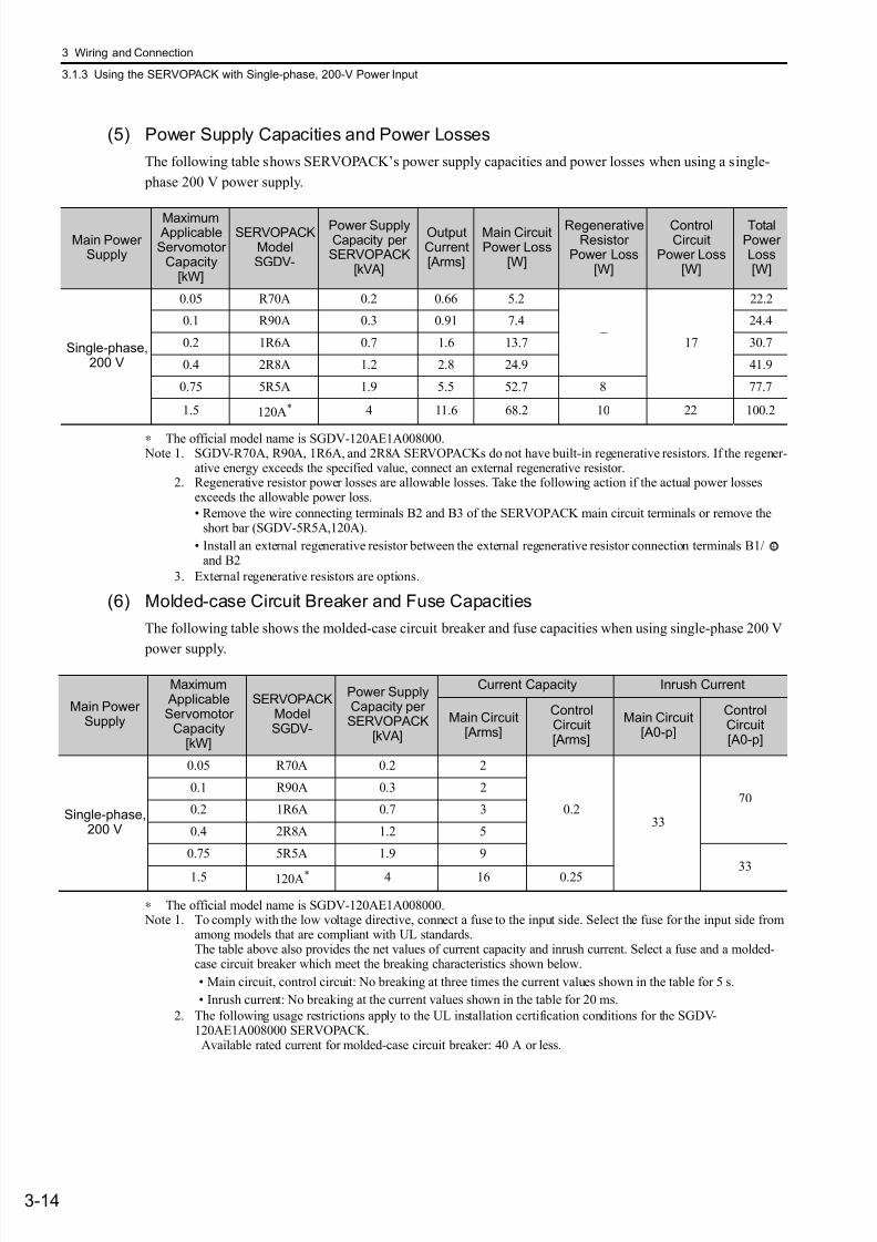
7/17/2019 Manual Yaskawa_servo_drive.pdf
http://slidepdf.com/reader/full/manual-yaskawaservodrivepdf 58/328
3 Wiring and Connection
3.1.3 Using the SERVOPACK with Single-phase, 200-V Power Input
3-14
(5) Power Supply Capacities and Power Losses
The following table shows SERVOPACK’s power supply capacities and power losses when using a single-
phase 200 V power supply.
∗ The official model name is SGDV-120AE1A008000. Note 1. SGDV-R70A, R90A, 1R6A, and 2R8A SERVOPACKs do not have built-in regenerative resistors. If the regener-
ative energy exceeds the specified value, connect an external regenerative resistor.2. Regenerative resistor power losses are allowable losses. Take the following action if the actual power losses
exceeds the allowable power loss.
• Remove the wire connecting terminals B2 and B3 of the SERVOPACK main circuit terminals or remove theshort bar (SGDV-5R5A,120A).
• Install an external regenerative resistor between the external regenerative resistor connection terminals B1/and B2
3. External regenerative resistors are options.
(6) Molded-case Circuit Breaker and Fuse Capacities
The following table shows the molded-case circuit breaker and fuse capacities when using single-phase 200 V
power supply.
∗ The official model name is SGDV-120AE1A008000. Note 1. To comply with the low voltage directive, connect a fuse to the input side. Select the fuse for the input side from
among models that are compliant with UL standards.The table above also provides the net values of current capacity and inrush current. Select a fuse and a molded-case circuit breaker which meet the breaking characteristics shown below.
• Main circuit, control circuit: No breaking at three times the current values shown in the table for 5 s.
• Inrush current: No breaking at the current values shown in the table for 20 ms.
2. The following usage restrictions apply to the UL installation certification conditions for the SGDV-120AE1A008000 SERVOPACK. Available rated current for molded-case circuit breaker: 40 A or less.
Main PowerSupply
Maximum ApplicableServomotor
Capacity[kW]
SERVOPACKModelSGDV-
Power SupplyCapacity perSERVOPACK
[kVA]
OutputCurrent[Arms]
Main CircuitPower Loss
[W]
RegenerativeResistor
Power Loss[W]
ControlCircuit
Power Loss[W]
TotalPowerLoss[W]
Single-phase,200 V
0.05 R70A 0.2 0.66 5.2
– 17
22.2
0.1 R90A 0.3 0.91 7.4 24.4
0.2 1R6A 0.7 1.6 13.7 30.7
0.4 2R8A 1.2 2.8 24.9 41.9
0.75 5R5A 1.9 5.5 52.7 8 77.7
1.5 120A* 4 11.6 68.2 10 22 100.2
Main PowerSupply
Maximum ApplicableServomotor
Capacity[kW]
SERVOPACKModelSGDV-
Power SupplyCapacity perSERVOPACK
[kVA]
Current Capacity Inrush Current
Main Circuit[Arms]
ControlCircuit[Arms]
Main Circuit[A0-p]
ControlCircuit[A0-p]
Single-phase,200 V
0.05 R70A 0.2 2
0.233
700.1 R90A 0.3 2
0.2 1R6A 0.7 3
0.4 2R8A 1.2 5
0.75 5R5A 1.9 9
331.5 120A* 4 16 0.25
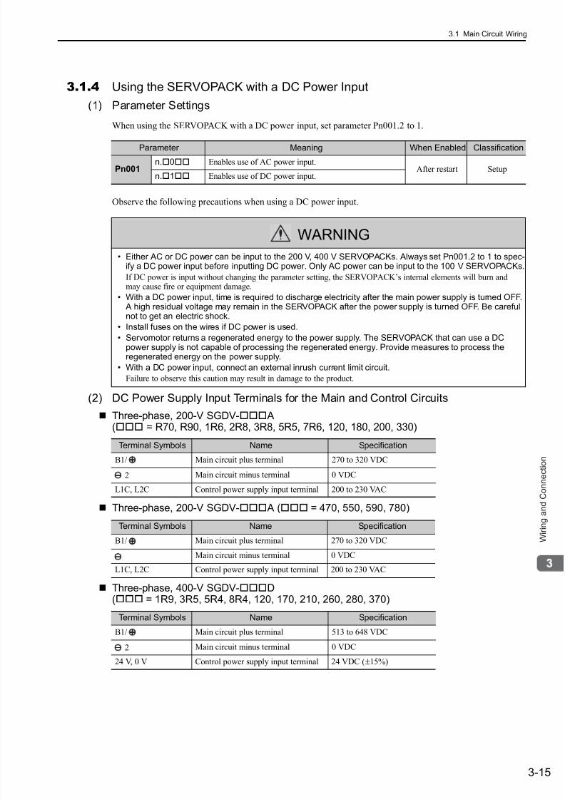
7/17/2019 Manual Yaskawa_servo_drive.pdf
http://slidepdf.com/reader/full/manual-yaskawaservodrivepdf 59/328
3.1 Main Circuit Wiring
3-15
W i r i n g a n d C o n n e c t i o n
3.1.4 Using the SERVOPACK with a DC Power Input
(1) Parameter Settings
When using the SERVOPACK with a DC power input, set parameter Pn001.2 to 1.
Observe the following precautions when using a DC power input.
(2) DC Power Supply Input Terminals for the Main and Control Circuits
Three-phase, 200-V SGDV-
A( = R70, R90, 1R6, 2R8, 3R8, 5R5, 7R6, 120, 180, 200, 330)
Three-phase, 200-V SGDV- A ( = 470, 550, 590, 780)
Three-phase, 400-V SGDV-D( = 1R9, 3R5, 5R4, 8R4, 120, 170, 210, 260, 280, 370)
Parameter Meaning When Enabled Classification
Pn001n.0 Enables use of AC power input.
After restart Setupn.1 Enables use of DC power input.
WARNING
• Either AC or DC power can be input to the 200 V, 400 V SERVOPACKs. Always set Pn001.2 to 1 to spec-ify a DC power input before inputting DC power. Only AC power can be input to the 100 V SERVOPACKs.
If DC power is input without changing the parameter setting, the SERVOPACK’s internal elements will burn andmay cause fire or equipment damage.
• With a DC power input, time is required to discharge electricity after the main power supply is turned OFF. A high residual voltage may remain in the SERVOPACK after the power supply is turned OFF. Be carefulnot to get an electric shock.
• Install fuses on the wires if DC power is used.
• Servomotor returns a regenerated energy to the power supply. The SERVOPACK that can use a DCpower supply is not capable of processing the regenerated energy. Provide measures to process theregenerated energy on the power supply.
• With a DC power input, connect an external inrush current limit circuit.
Failure to observe this caution may result in damage to the product.
Terminal Symbols Name Specification
B1/ Main circuit plus terminal 270 to 320 VDC
2 Main circuit minus terminal 0 VDC
L1C, L2C Control power supply input terminal 200 to 230 VAC
Terminal Symbols Name Specification
B1/ Main circuit plus terminal 270 to 320 VDC
Main circuit minus terminal 0 VDC
L1C, L2C Control power supply input terminal 200 to 230 VAC
Terminal Symbols Name Specification
B1/ Main circuit plus terminal 513 to 648 VDC
2 Main circuit minus terminal 0 VDC
24 V, 0 V Control power supply input terminal 24 VDC (±15%)
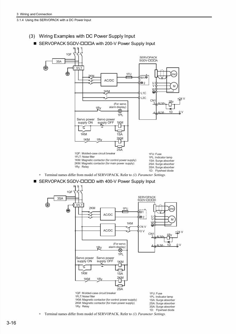
7/17/2019 Manual Yaskawa_servo_drive.pdf
http://slidepdf.com/reader/full/manual-yaskawaservodrivepdf 60/328
3 Wiring and Connection
3.1.4 Using the SERVOPACK with a DC Power Input
3-16
(3) Wiring Examples with DC Power Supply Input
SERVOPACK SGDV- A with 200-V Power Supply Input
∗ Terminal names differ from model of SERVOPACK. Refer to (1) Parameter Settings.
SERVOPACK SGDV-D with 400-V Power Supply Input
∗ Terminal names differ from model of SERVOPACK. Refer to (1) Parameter Settings.
1KM
1Ry
1PL
1KM
2KM
1SA
1Ry1KM
2SA
L1C
L2C
B1/
2
+*1FU
2KMENC
UV
WM
0 V
1Ry ALM+
ALM−
3
4 1D
CN1+24 V
1KM
AC/DC
1QF
R S T
1FLT
3SA
1QF: Molded-case circuit breaker
1FLT: Noise filter
1KM: Magnetic contactor (for control power supply)
2KM: Magnetic contactor (for main power supply)
1Ry: Relay
1FU: Fuse
1PL: Indicator lamp
1SA: Surge absorber
2SA: Surge absorber
3SA: Surge absorber
1D: Flywheel diode
SERVOPACKSGDV- A
(For servoalarm display)
supply ONServo power
supply OFFServo power
24 V
0 V
B1
2
1FU2KM ENC
UVW
M
0 V
1Ry ALM+
ALM−
3
4 1D
CN1+24 V
AC/DC
1QF
R S T
1FLT
*
3SA
AC/DC
1KM
1Ry
1PL
1KM
2KM
1SA
1Ry1KM
2SA
1KM
1QF: Molded-case circuit breaker1FLT: Noise f ilter
1KM: Magnetic contactor (for control power supply)
2KM: Magnetic contactor (for main power supply)
1Ry: Relay
1FU: Fuse1PL: Indicator lamp
1SA: Surge absorber
2SA: Surge absorber
3SA: Surge absorber
1D: Flywheel diode
SERVOPACKSGDV-D
(For servoalarm display)
supply ONServo power
supply OFFServo power

7/17/2019 Manual Yaskawa_servo_drive.pdf
http://slidepdf.com/reader/full/manual-yaskawaservodrivepdf 61/328
3.1 Main Circuit Wiring
3-17
W i r i n g a n d C o n n e c t i o n
3.1.5 Using More Than One SERVOPACK
This section shows an example of the wiring when more than one SERVOPACK is used and the precautions.
(1) Wiring Example
Connect the alarm output (ALM) terminals for the three SERVOPACKs in series to enable alarm detectionrelay 1Ry to operate.
When the alarm occurs, the ALM output signal transistor is turned OFF.
(2) Precautions
Multiple servos can share a single molded-case circuit breaker (1QF) and a noise filter. Always select a 1QFand a noise filter that has enough capacity for the total power capacity (load conditions) of those servos.
1KM
R S T
1QF
2KM
1Ry+24 V
L1L2
L3
L1C
CN1
CN1
CN1
3 ALM+
4 ALM -
0 V
L2C
1FLT
M
L1L2
L3
3 ALM+
4 ALM -
L1L2
L3
L1C
ID
3 ALM+
4 ALM -
L2C
M
M
L1C
L2C
3SA
1KM
1Ry
1PL
1KM
2KM
1SA
1Ry1KM
2SA
SERVOPACK
Servomotor
Servomotor
Servomotor
Relay
terminal
Relay
terminal
Relay
terminal
1QF:
1FLT:1KM: Magnetic contactor
(for control power supply)
2KM:
(for main power supply)
1Ry:
1PL:
1SA:
2SA:
3SA:
1D:
Molded-case circuit breaker
Noise filter
Relay
Magnetic contactor
Indicator lampSurge absorber
SERVOPACK
SERVOPACK
Surge absorber
Surge absorber
Flywheel diode
supply ON
Power supply
Relay
terminal
(For servo alarmdisplay)
Servo power supply OFFServo power
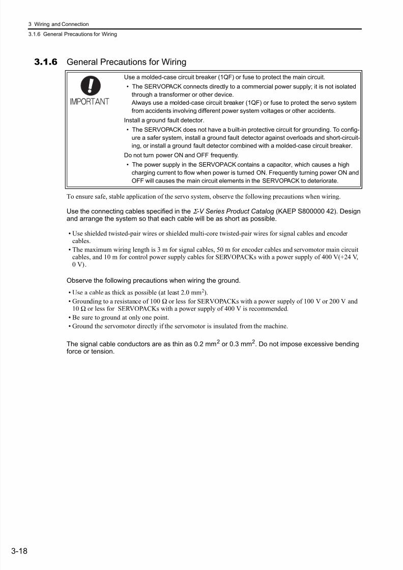
7/17/2019 Manual Yaskawa_servo_drive.pdf
http://slidepdf.com/reader/full/manual-yaskawaservodrivepdf 62/328
3 Wiring and Connection
3.1.6 General Precautions for Wiring
3-18
3.1.6 General Precautions for Wiring
To ensure safe, stable application of the servo system, observe the following precautions when wiring.
Use the connecting cables specified in the Σ -V Series Product Catalog (KAEP S800000 42). Designand arrange the system so that each cable will be as short as possible.
• Use shielded twisted-pair wires or shielded multi-core twisted-pair wires for signal cables and encodercables.
• The maximum wiring length is 3 m for signal cables, 50 m for encoder cables and servomotor main circuitcables, and 10 m for control power supply cables for SERVOPACKs with a power supply of 400 V(+24 V,0 V).
Observe the following precautions when wiring the ground.
• Use a cable as thick as possible (at least 2.0 mm2).
• Grounding to a resistance of 100 Ω or less for SERVOPACKs with a power supply of 100 V or 200 V and10 Ω or less for SERVOPACKs with a power supply of 400 V is recommended.
• Be sure to ground at only one point.
• Ground the servomotor directly if the servomotor is insulated from the machine.
The signal cable conductors are as thin as 0.2 mm2 or 0.3 mm2. Do not impose excessive bendingforce or tension.
Use a molded-case circuit breaker (1QF) or fuse to protect the main circuit.
• The SERVOPACK connects directly to a commercial power supply; it is not isolated
through a transformer or other device.
Always use a molded-case circuit breaker (1QF) or fuse to protect the servo system
from accidents involving different power system voltages or other accidents.
Install a ground fault detector.
• The SERVOPACK does not have a built-in protective circuit for grounding. To config-
ure a safer system, install a ground fault detector against overloads and short-circuit-
ing, or install a ground fault detector combined with a molded-case circuit breaker.
Do not turn power ON and OFF frequently.
• The power supply in the SERVOPACK contains a capacitor, which causes a high
charging current to flow when power is turned ON. Frequently turning power ON and
OFF will causes the main circuit elements in the SERVOPACK to deteriorate.

7/17/2019 Manual Yaskawa_servo_drive.pdf
http://slidepdf.com/reader/full/manual-yaskawaservodrivepdf 63/328
3.2 I/O Signal Connections
3-19
W i r i n g a n d C o n n e c t i o n
3.2 I/O Signal Connections
This section describes the names and functions of I/O signals (CN1). Also, connection examples by controlmethod are shown.
3.2.1 I/O Signal (CN1) Names and Functions
The following table shows the names and functions of I/O signals (CN1).
(1) Input Signals
Note 1. The functions allocated to /SI3, P-OT, N-OT, /SI4, /SI5, and /SI6 input signals can be changed by using the parameters. Refer to 3.3.1 Input Signal Allocations.
2. If the Forward run prohibited/Reverse run prohibited function is used, the software can be used to stop the SER-VOPACK. If the application does not satisfy the safety requirements, add an external circuit for safety reasons asrequired.
Regarding the allocation and use of I/O signals, they differ in accordance with the con-
nected option module. For details, refer to the manual for the command option module
that is connected.
Signal Pin No. Name FunctionRefer-ence
Section
/SI3 9Command optionmodule input 3
Connects the external input signal used in the commandoption module.
−
P-OT 7Forward run prohibited Overtravel prohibited: Stops servomotor when movable part
travels beyond the allowable range of motion.4.2.2
N-OT 8Reverse run prohibited
/SI4 10Command optionmodule input 4
Connects the external input signal used in the commandoption module.
−/SI5 11Command optionmodule input 5
/SI6 12Command optionmodule input 6
+24VIN 6Control power sup- ply input forsequence signal
Control power supply input for sequence signals.
Allowable voltage fluctuation range: 11 to 25 V
Note: The +24-V power supply is not included.
3.4.1
BAT(+) 14 Battery (+) inputConnecting pin for the absolute encoder backup battery. −
BAT(-) 15 Battery (−) input
/SI0 13General-purposeinput
Connects the external input signal used in the commandoption module.
−
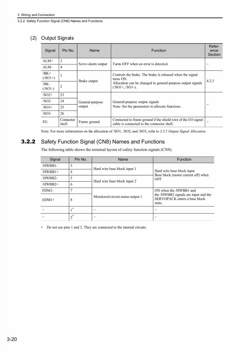
7/17/2019 Manual Yaskawa_servo_drive.pdf
http://slidepdf.com/reader/full/manual-yaskawaservodrivepdf 64/328
3 Wiring and Connection
3.2.2 Safety Function Signal (CN8) Names and Functions
3-20
(2) Output Signals
Note: For more information on the allocation of /SO1, /SO2, and /SO3, refer to 3.3.2 Output Signal Allocation.
3.2.2 Safety Function Signal (CN8) Names and Functions
The following table shows the terminal layout of safety function signals (CN8).
∗ Do not use pins 1 and 2. They are connected to the internal circuits.
Signal Pin No. Name FunctionRefer-ence
Section
ALM+ 3 Servo alarm output Turns OFF when an error is detected. −ALM- 4
/BK+
(/SO1+)1
Brake output
Controls the brake. The brake is released when the signalturns ON.Allocation can be changed to general-purpose output signals(/SO1+, /SO1-).
4.2.3/BK-
(/SO1-)2
/SO2+ 23
General-purposeoutput
General-purpose output signals
Note: Set the parameters to allocate functions.−
/SO2- 24
/SO3+ 25
/SO3- 26
FG
Connector
shell Frame ground
Connected to frame ground if the shield wire of the I/O signal
cable is connected to the connector shell. −
Signal Pin No. Name Function
/HWBB1- 3Hard wire base block input 1
Hard wire base block inputBase block (motor current off) whenOFF
/HWBB1+ 4
/HWBB2- 5Hard wire base block input 2
/HWBB2+ 6
EDM1- 7
Monitored circuit status output 1
ON when the /HWBB1 andthe /HWBB2 signals are input and theSERVOPACK enters a base blockstate.
EDM1+ 8
− 1* − −
− 2* − −

7/17/2019 Manual Yaskawa_servo_drive.pdf
http://slidepdf.com/reader/full/manual-yaskawaservodrivepdf 65/328
3.2 I/O Signal Connections
3-21
W i r i n g a n d C o n n e c t i o n
3.2.3 Example of I/O Signal Connections
The following diagram shows a typical connection example.
∗1. represents twisted-pair wires.
∗2. Connect when using an absolute encoder. When the encoder cable for the battery case is connected, do not connect a backup battery.
∗3. The 24 VDC power supply is not included. Use a power supply with double insulation or reinforced insulation.
∗4. For details, refer to the manual of the connected command option module.∗5. To turn the servomotor power ON, a safety device must be connected and the wiring to activate the safety function
must be done. When not using the safety function, use the SERVOPACK with the plug (JZSP-CVH05-E, provided asan accessory) inserted into the CN8.
Note: The functions allocated to the input signals /SI3, P-OT, N-OT, /SI0, /SI4, /SI5, and /SI6 and the output signals /SO1,/SO2, and /SO3 can be changed by using the parameters. Refer to 3.3.1 Input Signal Allocations and 3.3.2 OutputSignal Allocation.
SO1+ / BK+
SO1- / BK-
/SO2+
/SO2-
/SO3+
ALM+
ALM-
1
2
23
24
3
4
+24 V 3.3 kΩ
/SI1
/SI2
/SI3
/SI4
/SI5
6
8
10
9
11
12/SI6
/SI0BAT+
BAT-
13
14
15
7
/SO3-
PBO
PCO
/PBO
PAO/PAO
/PCO
19
25
26
1718
20
21
22
16 SG
*1
EDM1+
EDM1-
FG
/HWBB1+
/HWBB1-
/HWBB2+
/HWBB2-
24V
0V
CN8
6
3
4
5
CN1
8
7
Command option
module input 3*4
Command option
module input 4*4
Command option
module input 5*4
Command option
module input 6*4
Encoder outputpulses phase A
Encoder outputpulses phase B
Encoder outputpulses phase C
General-purpose outputs
Safety function signal*5
General-purpose input 0
Backup battery*2
(2.8 to 4.5 V)
Reverse run prohibited(Prohibited when OFF)
Forward run prohibited(Prohibited when OFF)
Servo alarm output(OFF for an alarm)
Photocoupler outputMax. operating voltage: 30 VDC
Max. operating current: 50 mA DC
Connect shield toconnector shell.
Connectorshell
SERVOPACK
Switch
fuse
Brake output(Brake released when ON)
Applicable line receiverSN75ALS175 manufactured byTexas Instruments or an MC3486equivalent
Signal ground
SGDV SERVOPACK
Control power supply
for sequence signal*3
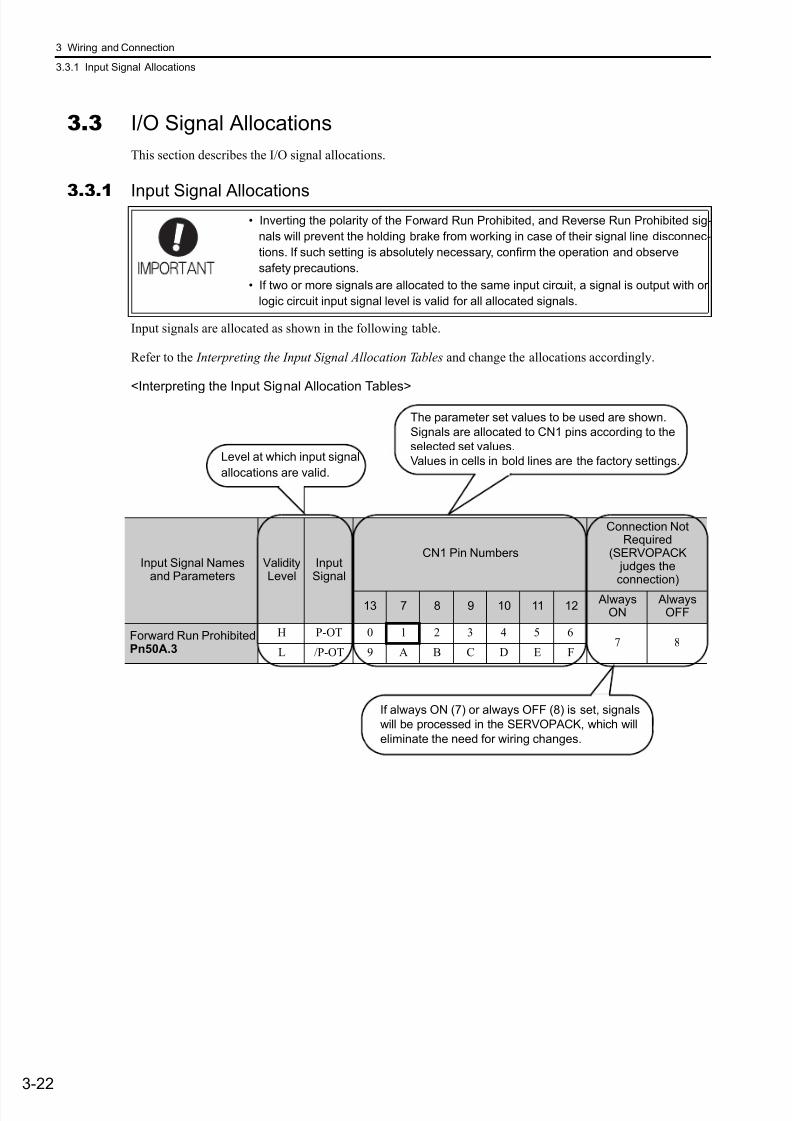
7/17/2019 Manual Yaskawa_servo_drive.pdf
http://slidepdf.com/reader/full/manual-yaskawaservodrivepdf 66/328
3 Wiring and Connection
3.3.1 Input Signal Allocations
3-22
3.3 I/O Signal Allocations
This section describes the I/O signal allocations.
3.3.1 Input Signal Allocations
Input signals are allocated as shown in the following table.
Refer to the Interpreting the Input Signal Allocation Tables and change the allocations accordingly.
<Interpreting the Input Signal Allocation Tables>
• Inverting the polarity of the Forward Run Prohibited, and Reverse Run Prohibited sig-
nals will prevent the holding brake from working in case of their signal line disconnec-
tions. If such setting is absolutely necessary, confirm the operation and observe
safety precautions.
• If two or more signals are allocated to the same input circuit, a signal is output with or
logic circuit input signal level is valid for all allocated signals.
Input Signal Namesand Parameters
ValidityLevel
InputSignal
CN1 Pin Numbers
Connection NotRequired
(SERVOPACK judges theconnection)
13 7 8 9 10 11 12 Always
ON Always
OFF
Forward Run ProhibitedPn50A.3
H P-OT 0 1 2 3 4 5 67 8
L /P-OT 9 A B C D E F
Level at which input signal
allocations are valid.
The parameter set values to be used are shown.
Signals are allocated to CN1 pins according to the
selected set values.
Values in cells in bold lines are the factory settings.
If always ON (7) or always OFF (8) is set, signals
will be processed in the SERVOPACK, which will
eliminate the need for wiring changes.
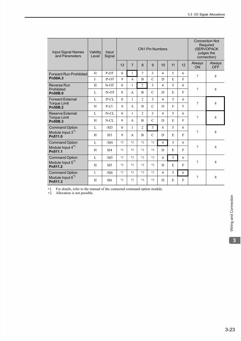
7/17/2019 Manual Yaskawa_servo_drive.pdf
http://slidepdf.com/reader/full/manual-yaskawaservodrivepdf 67/328
3.3 I/O Signal Allocations
3-23
W i r i n g a n d C o n n e c t i o n
∗1. For details, refer to the manual of the connected command option module.∗2. Allocation is not possible.
Input Signal Namesand Parameters
ValidityLevel
InputSignal
CN1 Pin Numbers
Connection NotRequired
(SERVOPACK judges theconnection)
13 7 8 9 10 11 12 Always
ON Always
OFF
Forward Run ProhibitedPn50A.3
H P-OT 0 1 2 3 4 5 67 8
L /P-OT 9 A B C D E F
Reverse RunProhibitedPn50B.0
H N-OT 0 1 2 3 4 5 67 8
L /N-OT 0 A B C D E F
Forward ExternalTorque LimitPn50B.2
L /P-CL 0 1 2 3 4 5 67 8
H P-CL 9 A B C D E F
Reserve ExternalTorque LimitPn50B.3
L /N-CL 0 1 2 3 4 5 67 8
H N-CL 9 A B C D E F
Command Option
Module Input 3*1
Pn511.0
L /SI3 0 1 2 3 4 5 6
7 8H SI3 9 A B C D E F
Command Option
Module Input 4*1
Pn511.1
L /SI4 *2 *2 *2 *2 4 5 6
7 8H SI4 *2 *2 *2 *2 D E F
Command Option
Module Input 5*1
Pn511.2
L /SI5 *2 *2 *2 *2 4 5 6
7 8H SI5 *2 *2 *2 *2 D E F
Command Option
Module Input 6
*1
Pn511.3
L /SI6 *2 *2 *2 *2 4 5 6
7 8H SI6 *2 *2 *2 *2 D E F
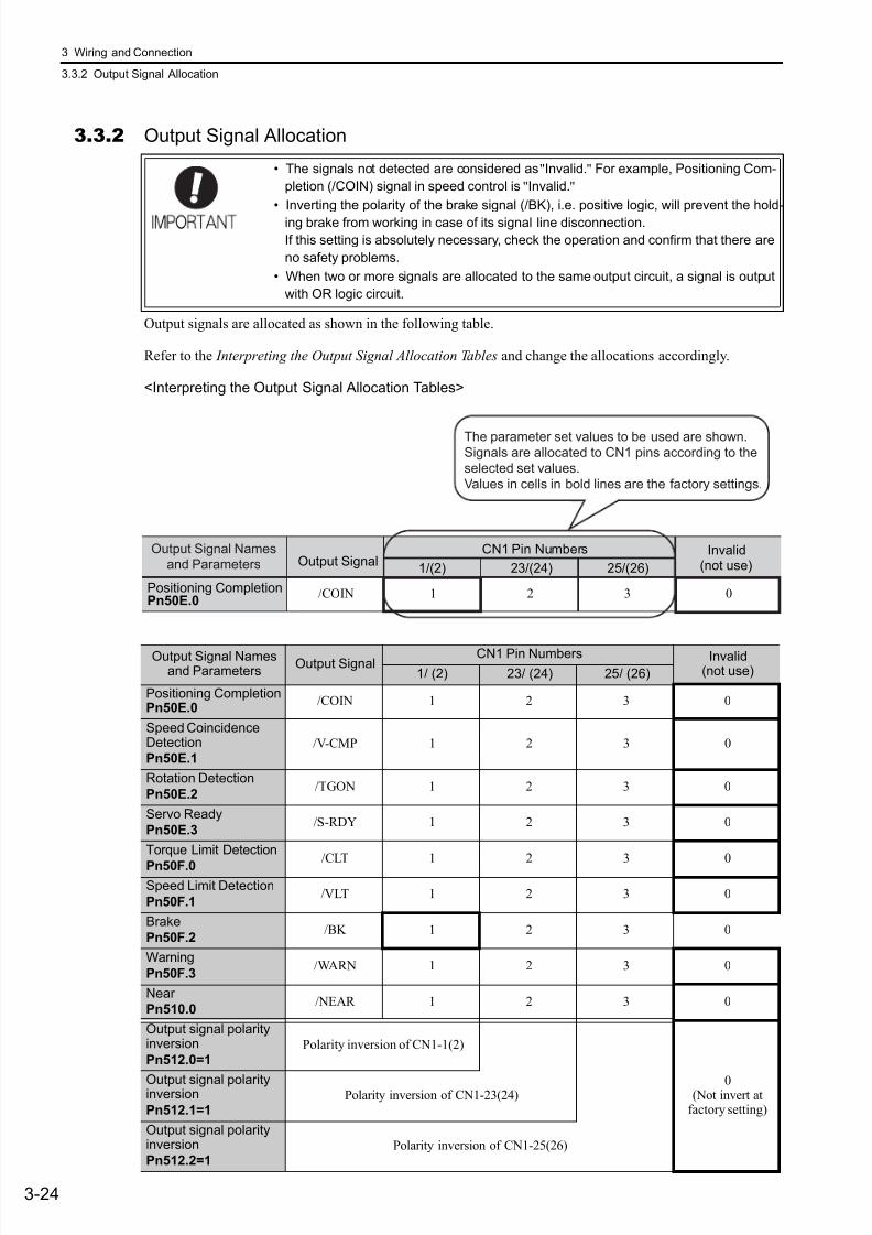
7/17/2019 Manual Yaskawa_servo_drive.pdf
http://slidepdf.com/reader/full/manual-yaskawaservodrivepdf 68/328
3 Wiring and Connection
3.3.2 Output Signal Allocation
3-24
3.3.2 Output Signal Allocation
Output signals are allocated as shown in the following table.
Refer to the Interpreting the Output Signal Allocation Tables and change the allocations accordingly.
<Interpreting the Output Signal Allocation Tables>
• The signals not detected are considered as "Invalid." For example, Positioning Com-
pletion (/COIN) signal in speed control is "Invalid."
• Inverting the polarity of the brake signal (/BK), i.e. positive logic, will prevent the hold-
ing brake from working in case of its signal line disconnection.
If this setting is absolutely necessary, check the operation and confirm that there are
no safety problems.
• When two or more signals are allocated to the same output circuit, a signal is output
with OR logic circuit.
Output Signal Namesand Parameters
Output SignalCN1 Pin Numbers Invalid
(not use)1/ (2) 23/ (24) 25/ (26)
Positioning CompletionPn50E.0
/COIN 1 2 3 0
Speed CoincidenceDetection
Pn50E.1/V-CMP 1 2 3 0
Rotation Detection
Pn50E.2/TGON 1 2 3 0
Servo Ready
Pn50E.3/S-RDY 1 2 3 0
Torque Limit Detection
Pn50F.0/CLT 1 2 3 0
Speed Limit Detection
Pn50F.1/VLT 1 2 3 0
Brake
Pn50F.2/BK 1 2 3 0
Warning
Pn50F.3/WARN 1 2 3 0
Near
Pn510.0/NEAR 1 2 3 0
Output signal polarityinversion
Pn512.0=1Polarity inversion of CN1-1(2)
0(Not invert at
factory setting)
Output signal polarityinversion
Pn512.1=1Polarity inversion of CN1-23(24)
Output signal polarityinversion
Pn512.2=1Polarity inversion of CN1-25(26)
Positioning CompletionPn50E.0
/COIN 1 2 3 0
1/(2) 23/(24) 25/(26)Output Signal
CN1 Pin Numbers Invalid(not use)
The parameter set values to be used are shown.Signals are allocated to CN1 pins according to the
selected set values.
Values in cells in bold lines are the factory settings.
Output Signal Namesand Parameters

7/17/2019 Manual Yaskawa_servo_drive.pdf
http://slidepdf.com/reader/full/manual-yaskawaservodrivepdf 69/328
3.4 Connection to Host Controller
3-25
W i r i n g a n d C o n n e c t i o n
3.4 Connection to Host Controller
This section shows examples of SERVOPACK I/O signal connection to the host controller.
3.4.1Sequence Input Circuits
(1) Photocoupler Input Circuit
CN1 connector terminals 6 to 13 are explained below.
The sequence input circuit interface connects through a relay or open-collector transistor circuit. Select a low-current relay if a relay is used. Otherwise, a faulty contact will result.
Note: The 24 VDC external power supply capacity must be 50 mA minimum.
The SERVOPACK’s I/O circuit uses bidirectional photocoupler. Select either the sink circuit or the source cir-cuit according to the specifications required for each machine.
Note: • The connection example in section 3.2.3 shows the connection using the sink circuit.
• The polarity for turning the input signal ON or OFF differs between the sink circuit and the source circuit.
Relay Circuit Example Open-collector Circuit Example
Sink Circuit Source Circuit
Input Signal Polarities Input Signal Polarities
Signal LevelVoltageLevel
Contact Signal LevelVoltageLevel
Contact
ON Low (L) level 0 V Close ON High (H) level 24 V Close
OFF High (H) level 24 V Open OFF Low (L) level 0 V Open
SERVOPACK
24 VDC +24 VIN 3.3 kΩ
/SI3
SERVOPACK
24 VDC +24 VIN 3.3 kΩ
/SI3
SERVOPACK input
24 V
+ – SERVOPACK input
24 V
+ –
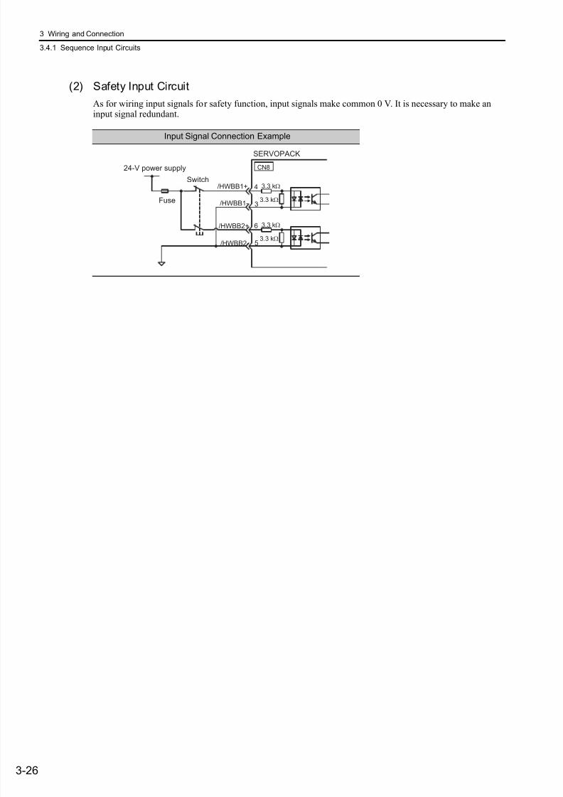
7/17/2019 Manual Yaskawa_servo_drive.pdf
http://slidepdf.com/reader/full/manual-yaskawaservodrivepdf 70/328
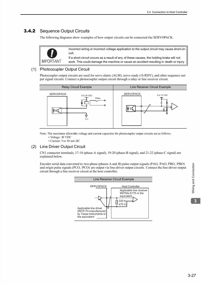
7/17/2019 Manual Yaskawa_servo_drive.pdf
http://slidepdf.com/reader/full/manual-yaskawaservodrivepdf 71/328
3.4 Connection to Host Controller
3-27
W i r i n g a n d C o n n e c t i o n
3.4.2 Sequence Output Circuits
The following diagrams show examples of how output circuits can be connected the SERVOPACK.
(1) Photocoupler Output Circuit
Photocoupler output circuits are used for servo alarm (ALM), servo ready (/S-RDY), and other sequence out- put signal circuits. Connect a photocoupler output circuit through a relay or line receiver circuit.
Note: The maximum allowable voltage and current capacities for photocoupler output circuits are as follows.
• Voltage: 30 VDC
• Current: 5 to 50 mA DC
(2) Line Driver Output Circuit
CN1 connector terminals, 17-18 (phase-A signal), 19-20 (phase-B signal), and 21-22 (phase-C signal) areexplained below.
Encoder serial data converted to two-phase (phases A and B) pulse output signals (PAO, /PAO, PBO, /PBO)and origin pulse signals (PCO, /PCO) are output via line-driver output circuits. Connect the line-driver outputcircuit through a line receiver circuit at the host controller.
Incorrect wiring or incorrect voltage application to the output circuit may cause short-cir-cuit.
If a short-circuit occurs as a result of any of these causes, the holding brake will not
work. This could damage the machine or cause an accident resulting in death or injury.
Relay Circuit Example Line Receiver Circuit Example
Relay
5 to 24 VDCSERVOPACK
0 V
SERVOPACK5 to 12 VDC
Line Receiver Circuit Example
Applicable line receiverSN75ALS175 or theequivalent
Host Controller
220 to
470 Ω
SERVOPACK
Applicable line driver SN75174 manufacturedby Texas Instruments orthe equivalent
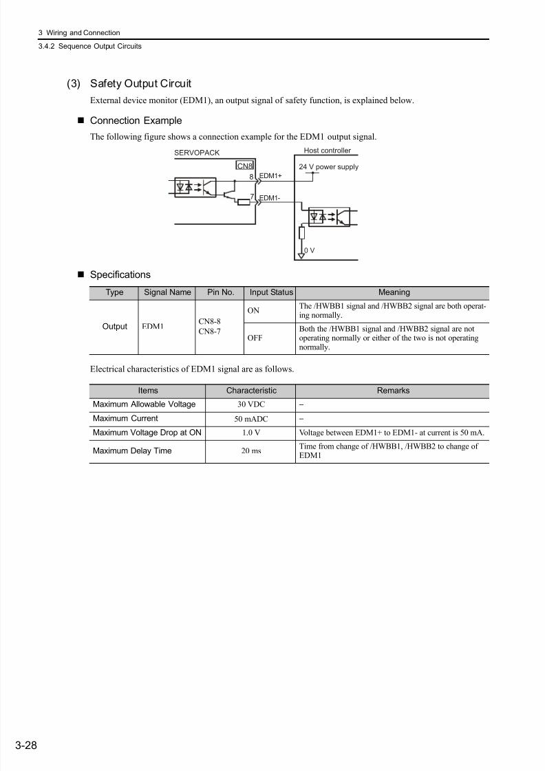
7/17/2019 Manual Yaskawa_servo_drive.pdf
http://slidepdf.com/reader/full/manual-yaskawaservodrivepdf 72/328
3 Wiring and Connection
3.4.2 Sequence Output Circuits
3-28
(3) Safety Output Circuit
External device monitor (EDM1), an output signal of safety function, is explained below.
Connection Example
The following figure shows a connection example for the EDM1 output signal.
Specifications
Electrical characteristics of EDM1 signal are as follows.
Host controller
24 V power supply
SERVOPACK
EDM1+
EDM1-
0 V
8
7
CN8
Type Signal Name Pin No. Input Status Meaning
Output EDM1CN8-8
CN8-7
ONThe /HWBB1 signal and /HWBB2 signal are both operat-ing normally.
OFFBoth the /HWBB1 signal and /HWBB2 signal are notoperating normally or either of the two is not operatingnormally.
Items Characteristic Remarks
Maximum Allowable Voltage 30 VDC −Maximum Current 50 mADC −
Maximum Voltage Drop at ON 1.0 V Voltage between EDM1+ to EDM1- at current is 50 mA.
Maximum Delay Time 20 msTime from change of /HWBB1, /HWBB2 to change ofEDM1
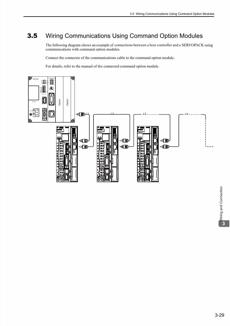
7/17/2019 Manual Yaskawa_servo_drive.pdf
http://slidepdf.com/reader/full/manual-yaskawaservodrivepdf 73/328
3.5 Wiring Communications Using Command Option Modules
3-29
W i r i n g a n d C o n n e c t i o n
3.5 Wiring Communications Using Command Option Modules
The following diagram shows an example of connections between a host controller and a SERVOPACK usingcommunications with command option modules.
Connect the connector of the communications cable to the command option module.
For details, refer to the manual of the connected command option module.
L3 LnL1 L2
DC24V
DC 0V
MP2300
TEST
RDY
ALM
TX
RUN
ERR
BAT
MONCNFG
INTSUP
STOP
SW1
OFF ON
BATTERY
CPU I/O
M-I/II
218IF-01
ERR
COL
RX
RUN
STRX
TX
INIT
TEST
ONOFF
PORT
10Base-T
O p t i o n
O p t i o n
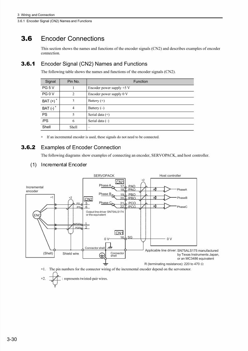
7/17/2019 Manual Yaskawa_servo_drive.pdf
http://slidepdf.com/reader/full/manual-yaskawaservodrivepdf 74/328
3 Wiring and Connection
3.6.1 Encoder Signal (CN2) Names and Functions
3-30
3.6 Encoder Connections
This section shows the names and functions of the encoder signals (CN2) and describes examples of encoderconnection.
3.6.1 Encoder Signal (CN2) Names and Functions
The following table shows the names and functions of the encoder signals (CN2).
∗ If an incremental encoder is used, these signals do not need to be connected.
3.6.2 Examples of Encoder Connection
The following diagrams show examples of connecting an encoder, SERVOPACK, and host controller.
(1) Incremental Encoder
∗1. The pin numbers for the connector wiring of the incremental encoder depend on the servomotor.
∗2. : represents twisted-pair wires.
Signal Pin No. Function
PG 5 V 1 Encoder power supply +5 V
PG 0 V 2 Encoder power supply 0 V
BAT (+) * 3 Battery (+)
BAT (-) * 4 Battery (–)
PS 5 Serial data (+)
/PS 6 Serial data (–)
Shell Shell –
19
0 VSG16 0 V
PAO/P AO
PBO/PBO
PCO/PCO
12
56
CN2
1718
20
2122
ENC
CN1
Applicable line driver: SN75ALS175 manufactured
by Texas Instruments Japan,
or an MC3486 equivalent
CN1
R
R
RPS
/PS
PG5V
PG0V
Incremental
encoder
Shield wire(Shell)
Connector shell
Connectorshell
Output line driver SN75ALS174or the equivalent
Phase APhaseA
Phase BPhaseB
Phase C
PhaseC
SERVOPACK Host controller
R (terminating resistance): 220 to 470 Ω
∗1 ∗2
∗2
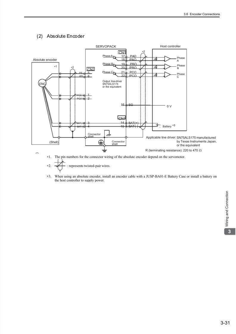
7/17/2019 Manual Yaskawa_servo_drive.pdf
http://slidepdf.com/reader/full/manual-yaskawaservodrivepdf 75/328
3.6 Encoder Connections
3-31
W i r i n g a n d C o n n e c t i o n
(2) Absolute Encoder
∗1. The pin numbers for the connector wiring of the absolute encoder depend on the servomotor.
∗2. : represents twisted-pair wires.
∗3. When using an absolute encoder, install an encoder cable with a JUSP-BA01-E Battery Case or install a battery onthe host controller to supply power.
/PCO
ENC
34
1415
BATBAT
(+)(-)
CN2
1718
1920
2122
CN1
SG16
PAO/P AO
PBO/PBO
PCO
CN1
R
R
R
+-
56
12
PG5 V
PG0 V
PS
/PS
BAT (+)
BAT (-)
0 V
Absolute encoder
(Shell)
SERVOPACK
Phase A
Phase B
Phase C
Connectorshell
Connectorshell
∗2
∗3
∗2∗1
Phase A
PhaseB
PhaseC
Host controller
Battery
Output line-driverSN75ALS174or the equivalent
Applicable line driver: SN75ALS175 manufactured
by Texas Instruments Japan,
or the equivalent
R (terminating resistance): 220 to 470 Ω

7/17/2019 Manual Yaskawa_servo_drive.pdf
http://slidepdf.com/reader/full/manual-yaskawaservodrivepdf 76/328
3 Wiring and Connection
3.7.1 Connecting Regenerative Resistors
3-32
3.7 Regenerative Resistors Connections
If the ability to absorb regenerative energy is insufficient, connect an external regenerative resistor in thefollowing manner and set the regenerative resistor capacity in Pn600. As for precautions on selecting a regen-erative resistor and its specifications, refer to Σ -V series Product Catalog (KAEP S800000 42).
3.7.1 Connecting Regenerative Resistors
The following instructions show how to connect the regenerative resistors and SERVOPACKs.
(1) SERVOPACKs: Model SGDV-R70F, R90F, 2R1F, 2R8F, R70A, R90A, 1R6A, 2R8A
Install an external regenerative resistor between the B1/ and B2 terminals. Make the settings for the regener-ative resistor after it is connected. For information setting the regenerative resistor, refer to 3.7.2 Setting
Regenerative Resistor Capacity.
(2) SERVOPACKs: Model SGDV-3R8A, 5R5A, 7R6A, 120A, 180A, 200A, 330A, 1R9D,3R5D, 5R4D, 8R4D, 120D, 170D
Disconnect the wiring between the SERVOPACK’s B2 and B3 terminals and connect an external regenerativeresistor between the B1/ and B2 terminals. Make the settings for the regenerative resistor after it is con-nected. For information setting the regenerative resistor, refer to 3.7.2 Setting Regenerative Resistor Capacity.
Note: Be sure to take out the lead wire between the B2 and B3 terminals.
WARNING
• Be sure to connect the regenerative resistor correctly.
Failure to observe this warning may result in fire or damage to the product.
Enalarged View
Enalarged View

7/17/2019 Manual Yaskawa_servo_drive.pdf
http://slidepdf.com/reader/full/manual-yaskawaservodrivepdf 77/328
7/17/2019 Manual Yaskawa_servo_drive.pdf
http://slidepdf.com/reader/full/manual-yaskawaservodrivepdf 78/328
7/17/2019 Manual Yaskawa_servo_drive.pdf
http://slidepdf.com/reader/full/manual-yaskawaservodrivepdf 79/328
3.8 Noise Control and Measures for Harmonic Suppression
3-35
W i r i n g a n d C o n n e c t i o n
3.8 Noise Control and Measures for Harmonic Suppression
This section describes the wiring for noise control and the DC reactor for harmonic suppression.
3.8.1Wiring for Noise Control
The SERVOPACK uses microprocessors. Therefore it may receive switching noise from peripheral devices.
To prevent the noise from the SERVOPACK or the peripheral devices from causing a malfunction of any oneof these devices, take the following precautions against noise as required.
• Position the input reference device and noise filter as close to the SERVOPACK as possible.
• Always install a surge absorber in the relay, solenoid and electromagnetic contactor coils.
• Do not bundle or run the main circuit cables together with the I/O signal cables in the same duct. Keep themain circuit cables separated from the I/O signal cables with a gap of at least 30 cm.
• Do not share the power supply with an electric welder or electrical discharge machine. When the SERVO-PACK is placed near a high-frequency generator, install a noise filter on the input side of the main circuit
power supply cables and control power supply cables. As for the wiring of noise filter, refer to (1) Noise Fil-ter .
• Take the grounding measures correctly. As for the grounding, refer to (2) Correct Grounding.
• Because the SERVOPACK is designed as an industrial device, it provides no mecha-
nism to prevent noise interference.
• The SERVOPACK uses high-speed switching elements in the main circuit. Therefore
peripheral devices may receive switching noise. If the equipment is to be used near
private houses or if radio interference is a problem, take countermeasures against
noise.
• Refer to 2.4 EMC Installation Conditions in the Σ-V Series User’s Manual Setup Rota-
tional Motor (SIEP S800000 43) if installation conditions of the EMC directive must be
satisfied.
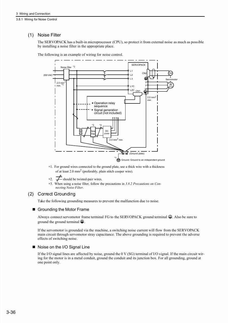
7/17/2019 Manual Yaskawa_servo_drive.pdf
http://slidepdf.com/reader/full/manual-yaskawaservodrivepdf 80/328
3 Wiring and Connection
3.8.1 Wiring for Noise Control
3-36
(1) Noise Filter
The SERVOPACK has a built-in microprocessor (CPU), so protect it from external noise as much as possible by installing a noise filter in the appropriate place.
The following is an example of wiring for noise control.
∗1. For ground wires connected to the ground plate, use a thick wire with a thickness
of at least 2.0 mm2 (preferably, plain stitch cooper wire).
∗2. should be twisted-pair wires.
∗3. When using a noise filter, follow the precautions in 3.8.2 Precautions on Con-necting Noise Filter .
(2) Correct Grounding
Take the following grounding measures to prevent the malfunction due to noise.
Grounding the Motor Frame
Always connect servomotor frame terminal FG to the SERVOPACK ground terminal . Also be sure to
ground the ground terminal .
If the servomotor is grounded via the machine, a switching noise current will flow from the SERVOPACKmain circuit through servomotor stray capacitance. The above grounding is required to prevent the adverseeffects of switching noise.
Noise on the I/O Signal Line
If the I/O signal lines are affected by noise, ground the 0 V (SG) terminal of I/O signal. If the main circuit wir-ing for the motor is in a metal conduit, ground the conduit and its junction box. For all grounding, ground atone point only.
U
W
V
L2
L1
L3
L2C
L1C
CN2
CN1
ENC
(FG)M
SERVOPACK
Operation relaysequence
Signal generation
circuit (not included)
Noise
Filter
DCpower
(Ground plate)
2.0 mm
min.
2
200 VAC
Noise filter *3
*1
*3 *2
2.0 mm2
min .
Ground: Ground to an independent ground
2.0 mm min.2
*1
Servomotor
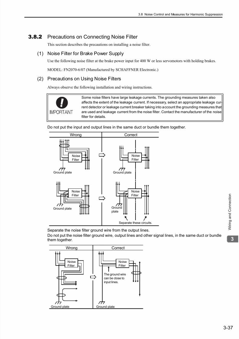
7/17/2019 Manual Yaskawa_servo_drive.pdf
http://slidepdf.com/reader/full/manual-yaskawaservodrivepdf 81/328
3.8 Noise Control and Measures for Harmonic Suppression
3-37
W i r i n g a n d C o n n e c t i o n
3.8.2 Precautions on Connecting Noise Filter
This section describes the precautions on installing a noise filter.
(1) Noise Filter for Brake Power Supply
Use the following noise filter at the brake power input for 400 W or less servomotors with holding brakes.
MODEL: FN2070-6/07 (Manufactured by SCHAFFNER Electronic.)
(2) Precautions on Using Noise Filters
Always observe the following installation and wiring instructions.
Do not put the input and output lines in the same duct or bundle them together.
Separate the noise filter ground wire from the output lines.
Do not put the noise filter ground wire, output lines and other signal lines, in the same duct or bundlethem together.
Some noise filters have large leakage currents. The grounding measures taken also
affects the extent of the leakage current. If necessary, select an appropriate leakage cur-
rent detector or leakage current breaker taking into account the grounding measures that
are used and leakage current from the noise filter. Contact the manufacturer of the noise
filter for details.
Ground plate
Ground plate
Ground plate
Ground
plate
Noise
Filter
Noise
Filter
Separate these circuits.
Noise
Filter
Wrong Correct
Noise
Filter
Ground plate Ground plate
Noise
Filter
Noise
Filter
The ground wire
can be close to
input lines.
Wrong Correct
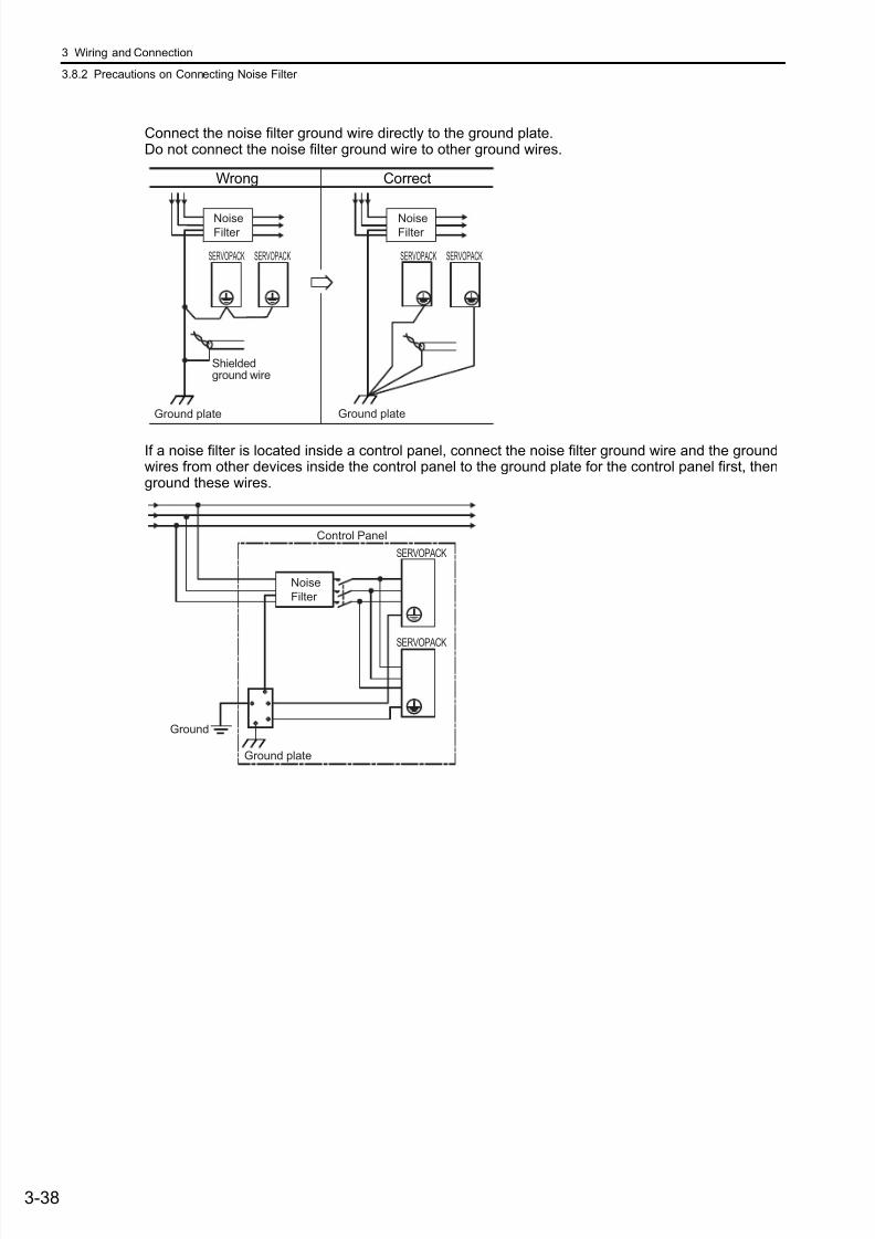
7/17/2019 Manual Yaskawa_servo_drive.pdf
http://slidepdf.com/reader/full/manual-yaskawaservodrivepdf 82/328
3 Wiring and Connection
3.8.2 Precautions on Connecting Noise Filter
3-38
Connect the noise filter ground wire directly to the ground plate.Do not connect the noise filter ground wire to other ground wires.
If a noise filter is located inside a control panel, connect the noise filter ground wire and the groundwires from other devices inside the control panel to the ground plate for the control panel first, thenground these wires.
Ground plate Ground plate
Shieldedground wire
NoiseFilter
NoiseFilter
SERVOPACK SERVOPACK SERVOPACK SERVOPACK
Wrong Correct
Noise
Filter
Control Panel
Ground
SERVOPACK
SERVOPACK
Ground plate
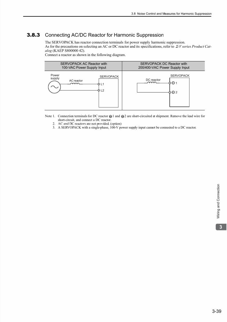
7/17/2019 Manual Yaskawa_servo_drive.pdf
http://slidepdf.com/reader/full/manual-yaskawaservodrivepdf 83/328
3.8 Noise Control and Measures for Harmonic Suppression
3-39
W i r i n g a n d C o n n e c t i o n
3.8.3 Connecting AC/DC Reactor for Harmonic Suppression
The SERVOPACK has reactor connection terminals for power supply harmonic suppression.As for the precautions on selecting an AC or DC reactor and its specifications, refer to Σ -V series Product Cat-alog (KAEP S800000 42).
Connect a reactor as shown in the following diagram.
Note 1. Connection terminals for DC reactor 1 and 2 are short-circuited at shipment. Remove the lead wire forshort-circuit, and connect a DC reactor.
2. AC and DC reactors are not provided. (option)3. A SERVOPACK with a single-phase, 100-V power supply input cannot be connected to a DC reactor.
SERVOPACK AC Reactor with100-VAC Power Supply Input
SERVOPACK DC Reactor with200/400-VAC Power Supply Input
L1
L2
SERVOPACK
AC reactor
Power supply
1
2
SERVOPACK
DC reactor

7/17/2019 Manual Yaskawa_servo_drive.pdf
http://slidepdf.com/reader/full/manual-yaskawaservodrivepdf 84/328
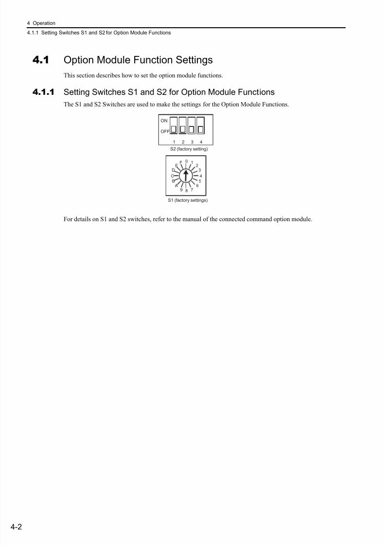
7/17/2019 Manual Yaskawa_servo_drive.pdf
http://slidepdf.com/reader/full/manual-yaskawaservodrivepdf 85/328
4 Operation
4.1.1 Setting Switches S1 and S2 for Option Module Functions
4-2
4.1 Option Module Function Settings
This section describes how to set the option module functions.
4.1.1Setting Switches S1 and S2 for Option Module FunctionsThe S1 and S2 Switches are used to make the settings for the Option Module Functions.
For details on S1 and S2 switches, refer to the manual of the connected command option module.
ON
OFF
1 2 3 4
0F 1E 2
D 3
8
4C
B 5 A 6
9 7
S1 (factory settings)
S2 (factory setting)
7/17/2019 Manual Yaskawa_servo_drive.pdf
http://slidepdf.com/reader/full/manual-yaskawaservodrivepdf 86/328
4.2 Settings for Common Basic Functions
4-3
O p e r a t i o n
4.2 Settings for Common Basic Functions
This section explains the settings for the common basic functions.
4.2.1Inspection and Checking before OperationTo ensure safe and correct operation, inspect and check the following items before starting operation.
(1) Servomotors
Inspect and check the following items and take appropriate measures before performing operation if any prob-lem exists.
• Are all wiring and connections correct?
• Are all nuts and bolts securely tightened?
• Does the motor have an oil seal? If so, is the oil shield in good condition without any damage?
• Does the motor have an oil seal? If so, does the oil have a coating?
Note: When performing operation on a servomotor that has been stored for a long period of time, perform the maintenance
and inspection according to the procedures described in 1.8 Inspection and Maintenance.
(2) SERVOPACKs
Inspect and check the following items and take appropriate measures before performing operation if any prob-lem exists.
• Are all wiring and connections correct?
• Is the correct power supply voltage being supplied to the SERVOPACK?
(3) Operating the Servomotor Alone
JOG operation of the SERVOPACK enables checking servomotor operation using speed control without con-nection to the host controller. For details, refer to the Σ -V Series Users Manual Setup Rotational Motor (SIEP
S800000 43). For details on how to perform operation using the command option module functions, refer tothe manual of the connected command option module.
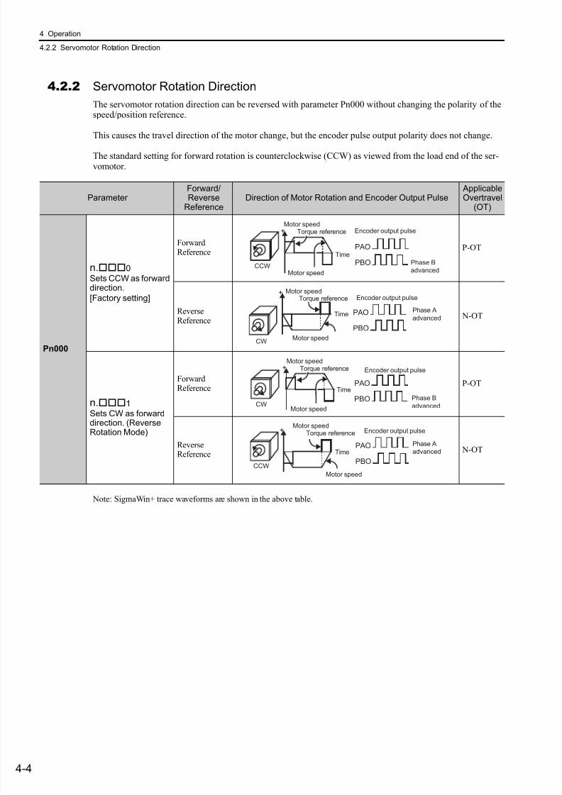
7/17/2019 Manual Yaskawa_servo_drive.pdf
http://slidepdf.com/reader/full/manual-yaskawaservodrivepdf 87/328
4 Operation
4.2.2 Servomotor Rotation Direction
4-4
4.2.2 Servomotor Rotation Direction
The servomotor rotation direction can be reversed with parameter Pn000 without changing the polarity of thespeed/position reference.
This causes the travel direction of the motor change, but the encoder pulse output polarity does not change.
The standard setting for forward rotation is counterclockwise (CCW) as viewed from the load end of the ser-vomotor.
Note: SigmaWin+ trace waveforms are shown in the above table.
Parameter Forward/Reverse
ReferenceDirection of Motor Rotation and Encoder Output Pulse
ApplicableOvertravel
(OT)
Pn000
n.0
Sets CCW as forwarddirection.
[Factory setting]
ForwardReference
P-OT
ReverseReference
N-OT
n.1
Sets CW as forwarddirection. (ReverseRotation Mode)
ForwardReference
P-OT
ReverseReference
N-OT
CCWPhase B
advanced
Time
Encoder output pulse
PAO
PBO
Motor speedTorque reference
Motor speed
+
CW
Phase A
advancedTime
Encoder output pulseMotor speed
Torque reference
Motor speed
PAO
PBO
+
PAO
PBOCW
Phase B
advanced
Encoder output pulse
Motor speedTorque reference
Motor speed
+
Time
CCW
Phase A
advanced
Encoder output pulse
PAO
PBO
+
Time
Motor speedTorque reference
Motor speed
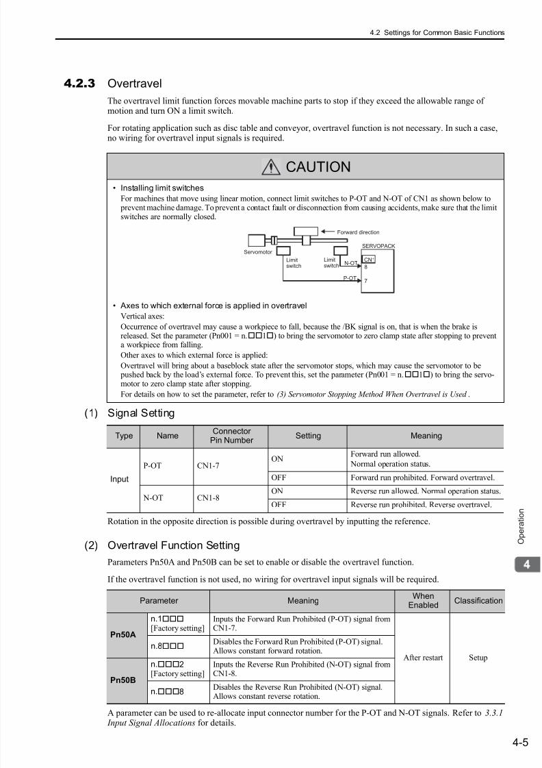
7/17/2019 Manual Yaskawa_servo_drive.pdf
http://slidepdf.com/reader/full/manual-yaskawaservodrivepdf 88/328
4.2 Settings for Common Basic Functions
4-5
O p e r a t i o n
4.2.3 Overtravel
The overtravel limit function forces movable machine parts to stop if they exceed the allowable range ofmotion and turn ON a limit switch.
For rotating application such as disc table and conveyor, overtravel function is not necessary. In such a case,no wiring for overtravel input signals is required.
(1) Signal Setting
Rotation in the opposite direction is possible during overtravel by inputting the reference.
(2) Overtravel Function Setting
Parameters Pn50A and Pn50B can be set to enable or disable the overtravel function.
If the overtravel function is not used, no wiring for overtravel input signals will be required.
A parameter can be used to re-allocate input connector number for the P-OT and N-OT signals. Refer to 3.3.1 Input Signal Allocations for details.
CAUTION
• Installing limit switches
For machines that move using linear motion, connect limit switches to P-OT and N-OT of CN1 as shown below to prevent machine damage. To prevent a contact fault or disconnection from causing accidents, make sure that the limitswitches are normally closed.
• Axes to which external force is applied in overtravel
Vertical axes:
Occurrence of overtravel may cause a workpiece to fall, because the /BK signal is on, that is when the brake isreleased. Set the parameter (Pn001 = n.1) to bring the servomotor to zero clamp state after stopping to preventa workpiece from falling.
Other axes to which external force is applied:
Overtravel will bring about a baseblock state after the servomotor stops, which may cause the servomotor to be pushed back by the load’s external force. To prevent this, set the parameter (Pn001 = n.1) to bring the servo-motor to zero clamp state after stopping.
For details on how to set the parameter, refer to (3) Servomotor Stopping Method When Overtravel is Used .
8
CN1
7P-OT
N-OTLimitswitch
SERVOPACK
Limitswitch
Forward direction
Servomotor
Type NameConnector
Pin Number Setting Meaning
Input
P-OT CN1-7ON
Forward run allowed.
Normal operation status.
OFF Forward run prohibited. Forward overtravel.
N-OT CN1-8ON Reverse run allowed. Normal operation status.
OFF Reverse run prohibited. Reverse overtravel.
Parameter MeaningWhen
EnabledClassification
Pn50A
n.1[Factory setting]
Inputs the Forward Run Prohibited (P-OT) signal fromCN1-7.
After restart Setup
n.8Disables the Forward Run Prohibited (P-OT) signal.Allows constant forward rotation.
Pn50B
n.2
[Factory setting]
Inputs the Reverse Run Prohibited (N-OT) signal from
CN1-8.
n.8Disables the Reverse Run Prohibited (N-OT) signal.Allows constant reverse rotation.

7/17/2019 Manual Yaskawa_servo_drive.pdf
http://slidepdf.com/reader/full/manual-yaskawaservodrivepdf 89/328
4 Operation
4.2.3 Overtravel
4-6
(3) Servomotor Stopping Method When Overtravel is Used
There are three servomotor stopping methods when an overtravel is used.
• Dynamic brake
By short-circuiting the electric circuits, the servomotor comes to a quick stop.• Decelerate to a stopStops by using emergency stop torque.
• Coast to a stopStops naturally, with no control, by using the friction resistance of the servomotor in operation.
After servomotor stopping, there are two modes.
• Coast modeStopped naturally, with no control, by using the friction resistance of the servomotor in operation.
• Zero clamp modeA mode forms a position loop by using the position reference zero.
The servomotor stopping method when an overtravel (P-OT, N-OT) signal is input while the servomotor isoperating can be set with parameter Pn001.
• A servomotor under torque control cannot be decelerated to a stop. The servomotor is stopped with thedynamic braking (DB) or coasts to a stop according to the setting of Pn001.0. After the servomotor stops,the servomotor will enter a coast state.
• For details on servomotor stopping methods after the SV_OFF command is received or an alarm occurs,refer to 4.2.8 Stopping Servomotor after Receiving Servo OFF Command or Alarm Occurrence.
When Servomotor Stopping Method is Set to Decelerate to Stop
Emergency stop torque can be set with Pn406.
• The setting unit is a percentage of the rated torque.
• The factory setting is 800% so that the setting is large enough a value to operate the servomotor at maximumtorque. The maximum value of emergency stop torque that is actually available, however, is limited to themaximum torque of the servomotor.
Parameter Stop MethodMode AfterStopping
When Enabled Classification
Pn001
n.00[Factory setting]
DBCoast
After restart Setupn.01
n.02 Coast
n.1Deceleration to a stop
Zero clamp
n.2 Coast
Pn406
Emergency Stop Torque Classification
Setting Range Setting Unit Factory Setting When Enabled
0 to 800 1% 800 Immediately Setup
Speed Position Torque
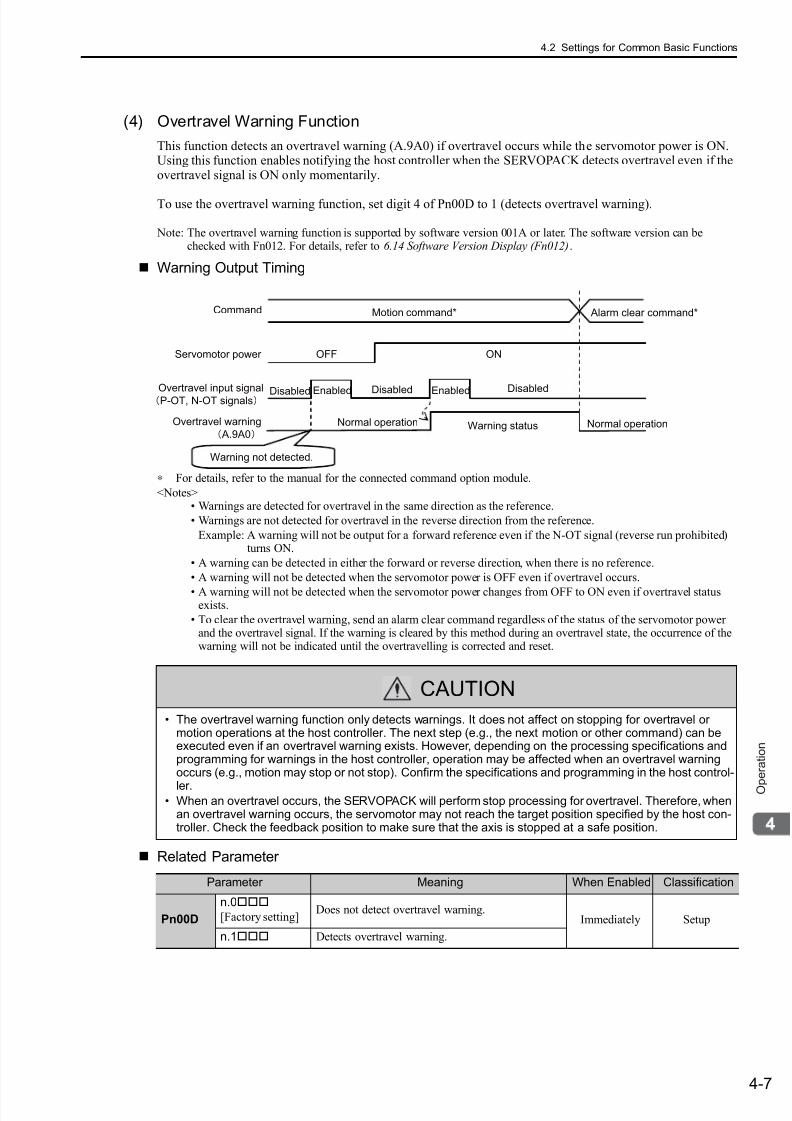
7/17/2019 Manual Yaskawa_servo_drive.pdf
http://slidepdf.com/reader/full/manual-yaskawaservodrivepdf 90/328
4.2 Settings for Common Basic Functions
4-7
O p e r a t i o n
(4) Overtravel Warning Function
This function detects an overtravel warning (A.9A0) if overtravel occurs while the servomotor power is ON.Using this function enables notifying the host controller when the SERVOPACK detects overtravel even if theovertravel signal is ON only momentarily.
To use the overtravel warning function, set digit 4 of Pn00D to 1 (detects overtravel warning).
Note: The overtravel warning function is supported by software version 001A or later. The software version can bechecked with Fn012. For details, refer to 6.14 Software Version Display (Fn012).
Warning Output Timing
∗ For details, refer to the manual for the connected command option module.
<Notes>• Warnings are detected for overtravel in the same direction as the reference.
• Warnings are not detected for overtravel in the reverse direction from the reference.
Example: A warning will not be output for a forward reference even if the N-OT signal (reverse run prohibited)turns ON.
• A warning can be detected in either the forward or reverse direction, when there is no reference.
• A warning will not be detected when the servomotor power is OFF even if overtravel occurs.
• A warning will not be detected when the servomotor power changes from OFF to ON even if overtravel statusexists.
• To clear the overtravel warning, send an alarm clear command regardless of the status of the servomotor powerand the overtravel signal. If the warning is cleared by this method during an overtravel state, the occurrence of thewarning will not be indicated until the overtravelling is corrected and reset.
Related Parameter
CAUTION
• The overtravel warning function only detects warnings. It does not affect on stopping for overtravel ormotion operations at the host controller. The next step (e.g., the next motion or other command) can beexecuted even if an overtravel warning exists. However, depending on the processing specifications andprogramming for warnings in the host controller, operation may be affected when an overtravel warningoccurs (e.g., motion may stop or not stop). Confirm the specifications and programming in the host control-
ler.• When an overtravel occurs, the SERVOPACK will perform stop processing for overtravel. Therefore, when
an overtravel warning occurs, the servomotor may not reach the target position specified by the host con-troller. Check the feedback position to make sure that the axis is stopped at a safe position.
Overtravel input signalP-OT, N-OT signals
Overtravel warning
A.9A0
Servomotor power
Warning not detected.
OFF ON
Enabled Disabled Enabled DisabledDisabled
Warning statusNormal operation Normal operation
Motion command* Alarm clear command*Command
Parameter Meaning When Enabled Classification
Pn00D
n.0
[Factory setting]Does not detect overtravel warning.
Immediately Setup
n.1 Detects overtravel warning.
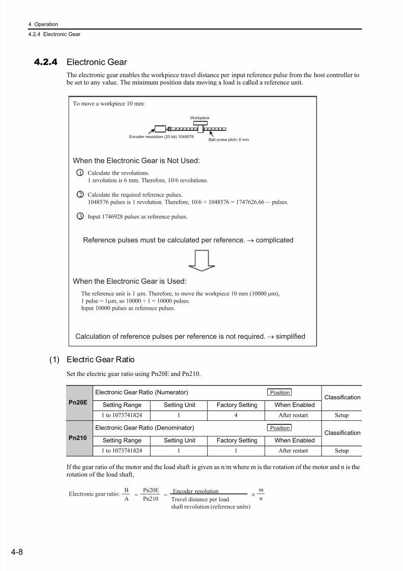
7/17/2019 Manual Yaskawa_servo_drive.pdf
http://slidepdf.com/reader/full/manual-yaskawaservodrivepdf 91/328
4 Operation
4.2.4 Electronic Gear
4-8
4.2.4 Electronic Gear
The electronic gear enables the workpiece travel distance per input reference pulse from the host controller to be set to any value. The minimum position data moving a load is called a reference unit.
(1) Electric Gear Ratio
Set the electric gear ratio using Pn20E and Pn210.
If the gear ratio of the motor and the load shaft is given as n/m where m is the rotation of the motor and n is therotation of the load shaft,
To move a workpiece 10 mm:
When the Electronic Gear is Not Used:
Calculate the revolutions.
1 revolution is 6 mm. Therefore, 10/6 revolutions.
Calculate the required reference pulses.
1048576 pulses is 1 revolution. Therefore, 10/6 × 1048576 = 1747626.66⋅⋅⋅ pulses.
Input 1746928 pulses as reference pulses.
Reference pulses must be calculated per reference. → complicated
When the Electronic Gear is Used:
The reference unit is 1 µm. Therefore, to move the workpiece 10 mm (10000µm),
1 pulse = 1µm, so 10000 ÷ 1 = 10000 pulses.Input 10000 pulses as reference pulses.
Calculation of reference pulses per reference is not required. → simplified
Ball screw pitch: 6 mm
Workpiece
Encoder resolution (20 bit) 1048576
1
2
3
Pn20E
Electronic Gear Ratio (Numerator)
ClassificationSetting Range Setting Unit Factory Setting When Enabled
1 to 1073741824 1 4 After restart Setup
Pn210
Electronic Gear Ratio (Denominator)Classification
Setting Range Setting Unit Factory Setting When Enabled
1 to 1073741824 1 1 After restart Setup
Position
Position
Electronic gear ratio: =
A
B
Pn210
Pn20E=
n
mEncoder resolution
Travel distance per loadshaft revolution (reference units)
×

7/17/2019 Manual Yaskawa_servo_drive.pdf
http://slidepdf.com/reader/full/manual-yaskawaservodrivepdf 92/328
4.2 Settings for Common Basic Functions
4-9
O p e r a t i o n
Encoder Resolution
Encoder resolution can be checked with servomotor model designation.
(2) Procedure for Setting the Electronic Gear Ratio
Set value electric gear differs depending on the machine specifications. Use the following procedure to set theelectronic gear ratio.
Electronic gear ratio setting range: 0.001 ≤ Electronic gear ratio (B/A) ≤ 4000
If the electronic gear ratio is outside this range, a parameter setting error (A.040) will be
output.
SGMV
Symbol Specification Encoder Resolutions
Symbol Specification Encoder Resolutions
3 20-bit absolute 1048576
D 20-bit incremental 1048576
A 13-bit incremental 8192
SGMPS
2 17-bit absolute 131072
C 17-bit incremental 131072
Step Operation
1Check machine specifications.
Check the gear ratio, ball screw pitch, and pulley diameter.
2Check the encoder resolution.
Check the encoder resolution for the servomotor used.
3Determine the reference unit used.
Determine the reference unit from the host controller, considering themachine specifications and positioning accuracy.
4Calculate the travel distance per load shaft revolution.
Calculate the number of reference units necessary to turn the load shaft onerevolution based on the previously determined reference units.
5Calculate the electronic gear ratio.
Use the electronic gear ratio equation to calculate the ratio (B/A).
6Set parameters.
Set parameters Pn20E and Pn210 using the calculated values.
7 Turn OFF the power and ON again to enable the settings.
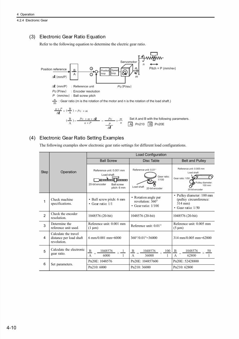
7/17/2019 Manual Yaskawa_servo_drive.pdf
http://slidepdf.com/reader/full/manual-yaskawaservodrivepdf 93/328
4 Operation
4.2.4 Electronic Gear
4-10
(3) Electronic Gear Ratio Equation
Refer to the following equation to determine the electric gear ratio.
(4) Electronic Gear Ratio Setting Examples
The following examples show electronic gear ratio settings for different load configurations.
A
B
nm
+
−
Pitch = P (mm/rev)
m
nServomotor
P GP/rev
P GP/rev Encoder resolution
Position
loop
Speed
loop
Position reference
∆
n × P
n × P
B
∆ A
∆
P
∆
∆
×
×
( )
mn
= P G × m
BA
( ) = = P G × m × P G Set A and B with the following parameters.
A Pn20EBPn210
P mm/revBall screw pitch
: Gear ratio (m is the rotation of the motor and n is the rotation of the load shaft.)
mm/P Reference unit
mm/P
Step Operation
Load Configuration
Ball Screw Disc Table Belt and Pulley
1Check machinespecifications.
• Ball screw pitch: 6 mm
• Gear ratio: 1/1
• Rotation angle perrevolution: 360°
• Gear ratio: 1/100
• Pulley diameter: 100 mm(pulley circumference:314 mm)
• Gear ratio: 1/50
2Check the encoderresolution.
1048576 (20-bit) 1048576 (20-bit) 1048576 (20-bit)
3Determine thereference unit used.
Reference unit: 0.001 mm(1 µm)
Reference unit: 0.01° Reference unit: 0.005 mm(5 µm)
4
Calculate the travel
distance per load shaftrevolution.
6 mm/0.001 mm=6000 360°/0.01°=36000 314 mm/0.005 mm=62800
5Calculate the electronicgear ratio.
6 Set parameters.Pn20E: 1048576 Pn20E: 104857600 Pn20E: 52428800
Pn210: 6000 Pn210: 36000 Pn210: 62800
Ball screwpitch: 6 mm
20-bit encoder
Load shaft
Reference unit: 0.001 mm
20-bit encoder Load shaft
Reference unit: 0.01°
Gear ratio:
1/100
Load shaft
Gear ratio: 1/50
Reference unit: 0.005 mm
Pulley diameter:100 mm
20-bit encoder
1048576
6000
1
1=
B
A
B
A
1048576
36000
100
1=
B
A
1048576
62800
50
1=
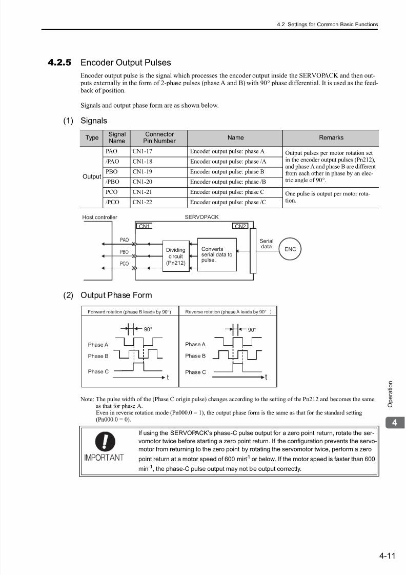
7/17/2019 Manual Yaskawa_servo_drive.pdf
http://slidepdf.com/reader/full/manual-yaskawaservodrivepdf 94/328
4.2 Settings for Common Basic Functions
4-11
O p e r a t i o n
4.2.5 Encoder Output Pulses
Encoder output pulse is the signal which processes the encoder output inside the SERVOPACK and then out- puts externally in the form of 2-phase pulses (phase A and B) with 90° phase differential. It is used as the feed- back of position.
Signals and output phase form are as shown below.
(1) Signals
(2) Output Phase Form
Note: The pulse width of the (Phase C origin pulse) changes according to the setting of the Pn212 and becomes the sameas that for phase A.Even in reverse rotation mode (Pn000.0 = 1), the output phase form is the same as that for the standard setting(Pn000.0 = 0).
TypeSignalName
ConnectorPin Number
Name Remarks
Output
PAO CN1-17 Encoder output pulse: phase A Output pulses per motor rotation setin the encoder output pulses (Pn212),and phase A and phase B are differentfrom each other in phase by an elec-tric angle of 90°.
/PAO CN1-18 Encoder output pulse: phase /A
PBO CN1-19 Encoder output pulse: phase B
/PBO CN1-20 Encoder output pulse: phase /B
PCO CN1-21 Encoder output pulse: phase C One pulse is output per motor rota-
tion./PCO CN1-22 Encoder output pulse: phase /C
ENC
CN1 CN2
SERVOPACKHost controller
Serialdata
PAO
PBO
PCO
Convertsserial data topulse.
Dividing
circuit
(Pn212)
If using the SERVOPACK’s phase-C pulse output for a zero point return, rotate the ser-
vomotor twice before starting a zero point return. If the configuration prevents the servo-
motor from returning to the zero point by rotating the servomotor twice, perform a zero
point return at a motor speed of 600 min-1 or below. If the motor speed is faster than 600
min-1, the phase-C pulse output may not be output correctly.
Phase A
Phase B
Phase C
90°
t
Phase A
Phase B
Phase C
t
Forward rotation (phase B leads by 90°) Reverse rotation (phase A leads by 90°
90°
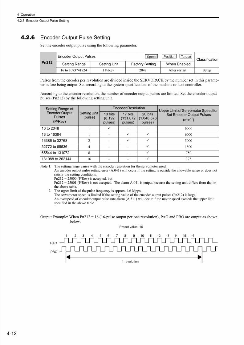
7/17/2019 Manual Yaskawa_servo_drive.pdf
http://slidepdf.com/reader/full/manual-yaskawaservodrivepdf 95/328
4 Operation
4.2.6 Encoder Output Pulse Setting
4-12
4.2.6 Encoder Output Pulse Setting
Set the encoder output pulse using the following parameter.
Pulses from the encoder per revolution are divided inside the SERVOPACK by the number set in this parame-ter before being output. Set according to the system specifications of the machine or host controller.
According to the encoder resolution, the number of encoder output pulses are limited. Set the encoder output pulses (Pn212) by the following setting unit.
Note 1. The setting range varies with the encoder resolution for the servomotor used.An encoder output pulse setting error (A.041) will occur if the setting is outside the allowable range or does notsatisfy the setting conditions.Pn212 = 25000 (P/Rev) is accepted, but
Pn212 = 25001 (P/Rev) is not accepted. The alarm A.041 is output because the setting unit differs from that inthe above table.
2. The upper limit of the pulse frequency is approx. 1.6 Mpps.The servomotor speed is limited if the setting value of the encoder output pulses (Pn212) is large.An overspeed of encoder output pulse rate alarm (A.511) will occur if the motor speed exceeds the upper limitspecified in the above table.
Output Example: When Pn212 = 16 (16-pulse output per one revolution), PAO and PBO are output as shown below.
Pn212
Encoder Output Pulses
ClassificationSetting Range Setting Unit Factory Setting When Enabled
16 to 1073741824 1 P/Rev 2048 After restart Setup
Speed Position Torque
Setting Range ofEncoder Output
Pulses
(P/Rev)
Setting Unit(pulse)
Encoder ResolutionUpper Limit of Servomotor Speed for
Set Encoder Output Pulses
(min-1
)
13 bits(8,192pulses)
17 bits(131,072pulses)
20 bits(1,048,576
pulses)
16 to 2048 1 – – 6000
16 to 16384 1 – 6000
16386 to 32768 2 – 3000
32772 to 65536 4 – – 1500
65544 to 131072 8 – – 750
131088 to 262144 16 – – 375
Preset value: 16
1 revolution
PAO
PBO
1 2 3 4 5 6 7 8 9 10 11 12 13 14 15 16

7/17/2019 Manual Yaskawa_servo_drive.pdf
http://slidepdf.com/reader/full/manual-yaskawaservodrivepdf 96/328
4.2 Settings for Common Basic Functions
4-13
O p e r a t i o n
4.2.7 Holding Brakes
A holding brake is a brake used to hold the position of the movable part of the machine when the SERVO-PACK is turned OFF so that movable part does not move due to gravity or external forces. Holding brakes are
built into servomotors with brakes.
The holding brake is used in the following cases.
There is a delay in the braking operation. Set the following ON/OFF timing.
∗1. For details, refer to the manual for the command option module that is connected.∗2. The operation delay time of the brake depends on the model. For details, refer to Brake Operation Delay Time shown
below.∗3. After the Servo ON command has been sent and 50 ms has passed since the brake was released, output the reference
from the host controller to the SERVOPACK.∗4. Use Pn506, Pn507, and Pn508 to set the timing of when the brake will be activated and when the servomotor power
will be turned OFF.
• The brake built into the servomotor with brakes is a de-energization brake, which is
used only to hold and cannot be used for braking. Use the holding brake only to hold
a stopped servomotor.
Servomotor Vertical Shaft
Holding brake
Shaft with External Force Applied
Movable part of machine
Holding brake
Movable part of
machine
Servomotor Externalforce
Prevents the movable part (table)
from moving due to external force.
Prevents themovable part frommoving due to itsown weight when thepower is OFF.
*2
*3
0
*2
*4
Servo ON command
Servomotor power
Brake signal (/BK)
Brake contact part
(lining)
Position reference/
Speed reference
Motor speed
OFF
OFF
OFF
OFF
OFF
OFF
ON
ON
ON
Brake release Brake appliedBrake applied
*1
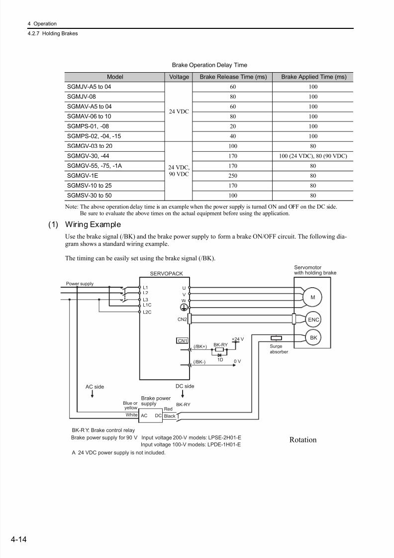
7/17/2019 Manual Yaskawa_servo_drive.pdf
http://slidepdf.com/reader/full/manual-yaskawaservodrivepdf 97/328
4 Operation
4.2.7 Holding Brakes
4-14
Note: The above operation delay time is an example when the power supply is turned ON and OFF on the DC side.Be sure to evaluate the above times on the actual equipment before using the application.
(1) Wiring Example
Use the brake signal (/BK) and the brake power supply to form a brake ON/OFF circuit. The following dia-gram shows a standard wiring example.
The timing can be easily set using the brake signal (/BK).
Brake Operation Delay Time
Model Voltage Brake Release Time (ms) Brake Applied Time (ms)
SGMJV-A5 to 04
24 VDC
60 100
SGMJV-08 80 100SGMAV-A5 to 04 60 100
SGMAV-06 to 10 80 100
SGMPS-01, -08 20 100
SGMPS-02, -04, -15 40 100
SGMGV-03 to 20
24 VDC,90 VDC
100 80
SGMGV-30, -44 170 100 (24 VDC), 80 (90 VDC)
SGMGV-55, -75, -1A 170 80
SGMGV-1E 250 80
SGMSV-10 to 25 170 80
SGMSV-30 to 50 100 80
M
BK
ENC
U
V
W
CN2
AC DC
BK-RY
BK-RY
+24 V
L1
L2L3L1C
L2C
(/BK+)
(/BK-)
CN1
1D 0 V
BK-R Y: Brake control relay
A 24 VDC power supply is not included.
Brake power supply for 90 V Input voltage 200-V models: LPSE-2H01-E
Input voltage 100-V models: LPDE-1H01-E
Servomotor with holding brakeSERVOPACK
Power supply
Red
Black
Blue oryellow
White
Brake powersupply
DC side AC side
Surge
absorber
Rotation

7/17/2019 Manual Yaskawa_servo_drive.pdf
http://slidepdf.com/reader/full/manual-yaskawaservodrivepdf 98/328
4.2 Settings for Common Basic Functions
4-15
O p e r a t i o n
(2) Brake Signal (/BK) Setting
This output signal controls the brake. The allocation of the /BK signal can be changed. Refer to (3) Brake Sig-nal (/BK) Allocation for allocation.
The /BK signal turns OFF (applies the brake) when an alarm is detected or the servomotor power is OFF. The brake OFF timing can be adjusted with Pn506.
• Select the optimum surge absorber in accordance with the applied brake current and
brake power supply.
When using the LPSE-2H01-E power supply: Z10D471 (Made by SEMITEC
Corporation)
When using the LPDE-1H01-E power supply: Z10D271 (Made by SEMITEC
Corporation)
When using the 24-V power supply: Z15D121 (Made by SEMITEC Corporation)
• After the surge absorber is connected, check the total time the brake is applied for the
system. Depending on the surge absorber, the total time the brake is applied can be
changed.
• Configure the relay circuit to apply the holding brake by the emergency stop.
• The allocation of the /BK signal can be changed. Refer to (3) Brake Signal (/BK) Allo-
cation to set the parameter Pn50F.
• When using a 24-V brake, separate the 24-VDC power supply from other power sup-
plies, such as the one used for the I/O signals of CN1 connectors. Always install the
24-VDC power supply separately. If the power supply is shared, the I/O signals might
malfunction.
Relay Circuit Example
0 V
Emergency stop5 to 24 VDC
SERVOPACK
Photocoupler
Type NameConnector
Pin Number Setting Meaning
Output /BK CN1-1, CN1-2ON (closed) Releases the brake.
OFF (open) Applies the brake.
The /BK signal is still ON during overtravel and the brake is still released.
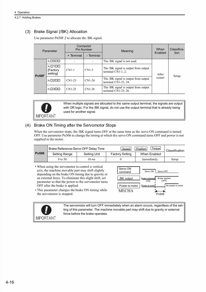
7/17/2019 Manual Yaskawa_servo_drive.pdf
http://slidepdf.com/reader/full/manual-yaskawaservodrivepdf 99/328
4 Operation
4.2.7 Holding Brakes
4-16
(3) Brake Signal (/BK) Allocation
Use parameter Pn50F.2 to allocate the /BK signal.
(4) Brake ON Timing after the Servomotor Stops
When the servomotor stops, the /BK signal turns OFF at the same time as the servo ON command is turnedOFF. Use parameter Pn506 to change the timing at which the servo ON command turns OFF and power is notsupplied to the motor.
Parameter
Connector
Pin Number MeaningWhen
EnabledClassifica-
tion+ Terminal - Terminal
Pn50F
n.0 – – The /BK signal is not used.
Afterrestart
Setup
n.1
[Factorysetting]
CN1-1 CN1-2The /BK signal is output from outputterminal CN1-1, 2.
n.2 CN1-23 CN1-24The /BK signal is output from outputterminal CN1-23, 24.
n.3 CN1-25 CN1-26The /BK signal is output from outputterminal CN1-25, 26.
When multiple signals are allocated to the same output terminal, the signals are output
with OR logic. For the /BK signal, do not use the output terminal that is already being
used for another signal.
Pn506
Brake Reference-Servo OFF Delay TimeClassification
Setting Range Setting Unit Factory Setting When Enabled
0 to 50 10 ms 0 Immediately Setup
Speed Position Torque
• When using the servomotor to control a verticalaxis, the machine movable part may shift slightlydepending on the brake ON timing due to gravity oran external force. To eliminate this slight shift, set
parameter so that the power to the servomotor turnsOFF after the brake is applied.
• This parameter changes the brake ON timing whilethe servomotor is stopped.
Servo ON
command
/BK output
Power to motor
Brake released
(ON)
Servo ON
Power to motor
Brake applied
(OFF)
Servo OFF
No power to motor
Pn506MECHA
The servomotor will turn OFF immediately when an alarm occurs, regardless of the set-ting of this parameter. The machine movable part may shift due to gravity or external
force before the brake operates.
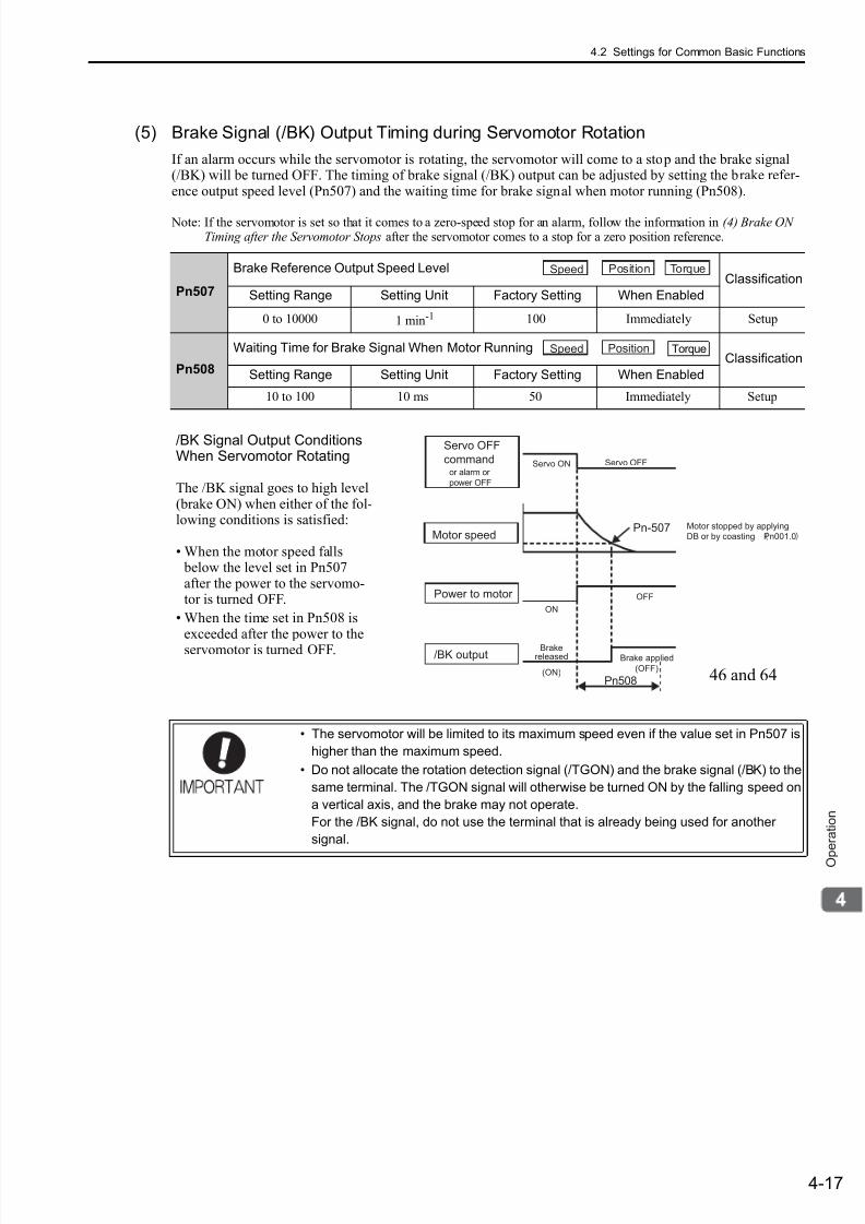
7/17/2019 Manual Yaskawa_servo_drive.pdf
http://slidepdf.com/reader/full/manual-yaskawaservodrivepdf 100/328
4.2 Settings for Common Basic Functions
4-17
O p e r a t i o n
(5) Brake Signal (/BK) Output Timing during Servomotor Rotation
If an alarm occurs while the servomotor is rotating, the servomotor will come to a stop and the brake signal(/BK) will be turned OFF. The timing of brake signal (/BK) output can be adjusted by setting the brake refer-ence output speed level (Pn507) and the waiting time for brake signal when motor running (Pn508).
Note: If the servomotor is set so that it comes to a zero-speed stop for an alarm, follow the information in (4) Brake ONTiming after the Servomotor Stops after the servomotor comes to a stop for a zero position reference.
Pn507
Brake Reference Output Speed LevelClassification
Setting Range Setting Unit Factory Setting When Enabled
0 to 10000 1 min-1 100 Immediately Setup
Pn508
Waiting Time for Brake Signal When Motor Running Classification
Setting Range Setting Unit Factory Setting When Enabled
10 to 100 10 ms 50 Immediately Setup
Speed Position Torque
Speed Position Torque
/BK Signal Output ConditionsWhen Servomotor Rotating
The /BK signal goes to high level(brake ON) when either of the fol-lowing conditions is satisfied:
• When the motor speed falls below the level set in Pn507after the power to the servomo-tor is turned OFF.
• When the time set in Pn508 isexceeded after the power to theservomotor is turned OFF.
Servo OFF
command
Motor speedPn-507
Servo ON Servo OFF
Pn508
Power to motor
ON
OFF
/BK outputBrake
released
(ON)
Brake applied
(OFF)
or alarm or
power OFF
Motor stopped by applying
DB or by coasting Pn001.0
46 and 64
• The servomotor will be limited to its maximum speed even if the value set in Pn507 is
higher than the maximum speed.
• Do not allocate the rotation detection signal (/TGON) and the brake signal (/BK) to the
same terminal. The /TGON signal will otherwise be turned ON by the falling speed on
a vertical axis, and the brake may not operate.
For the /BK signal, do not use the terminal that is already being used for another
signal.
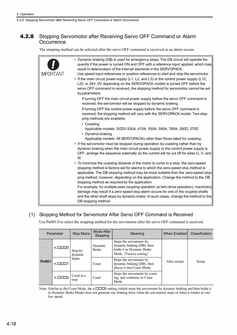
7/17/2019 Manual Yaskawa_servo_drive.pdf
http://slidepdf.com/reader/full/manual-yaskawaservodrivepdf 101/328
4 Operation
4.2.8 Stopping Servomotor after Receiving Servo OFF Command or Alarm Occurrence
4-18
4.2.8 Stopping Servomotor after Receiving Servo OFF Command or AlarmOccurrence
The stopping method can be selected after the servo OFF command is received or an alarm occurs.
(1) Stopping Method for Servomotor After Servo OFF Command is Received
Use Pn001.0 to select the stopping method for the servomotor after the servo OFF command is received.
Note: Similar to the Coast Mode, the n.0 setting (which stops the servomotor by dynamic braking and then holds it
in Dynamic Brake Mode) does not generate any braking force when the servomotor stops or when it rotates at verylow speed.
• Dynamic braking (DB) is used for emergency stops. The DB circuit will operate fre-quently if the power is turned ON and OFF with a reference input applied, which may
result in deterioration of the internal elements in the SERVOPACK.
Use speed input references or position references to start and stop the servomotor.
• If the main circuit power supply (L1, L2, and L3) or the control power supply (L1C,
L2C or 24V, 0V depending on the SERVOPACK model) is turned OFF before the
servo OFF command is received, the stopping method for servomotor cannot be set
by parameters.
If turning OFF the main circuit power supply before the servo OFF command is
received, the servomotor will be stopped by dynamic braking.
If turning OFF the control power supply before the servo OFF command is
received, the stopping method will vary with the SERVOPACK model. Two stop-
ping methods are available.
• Coasting
Applicable models: SGDV-330A, 470A, 550A, 590A, 780A, 280D, 370D
• Dynamic braking
Applicable models: All SERVOPACKs other than those listed for coasting.
• If the servomotor must be stopped during operation by coasting rather than by
dynamic braking when the main circuit power supply or the control power supply is
OFF, arrange the sequence externally so the current will be cut off for wires U, V, and
W.
• To minimize the coasting distance of the motor to come to a stop, the zero-speed
stopping method is factory-set for alarms to which the zero-speed stop method is
applicable. The DB stopping method may be more suitable than the zero-speed stop-
ping method, however, depending on the application. Change the method to the DB
stopping method as required by the application.
For example, for multiple axes coupling operation (a twin-drive operation), machinery
damage may result if a zero-speed stop alarm occurs for one of the coupled shafts
and the other shaft stops by dynamic brake. In such cases, change the method to the
DB stopping method.
Parameter Stop Mode
Mode After
Stopping Meaning When Enabled Classification
Pn001
n.0Stop bydynamic brake
DynamicBrake
Stops the servomotor bydynamic braking (DB), thenholds it in Dynamic Brake
Mode. [Factory setting]
After restart Setupn.1 Coast
Stops the servomotor bydynamic braking (DB), then places it into Coast Mode.
n.2Coast to astop
CoastStops the servomotor by coast-ing, and continues in CoastMode.
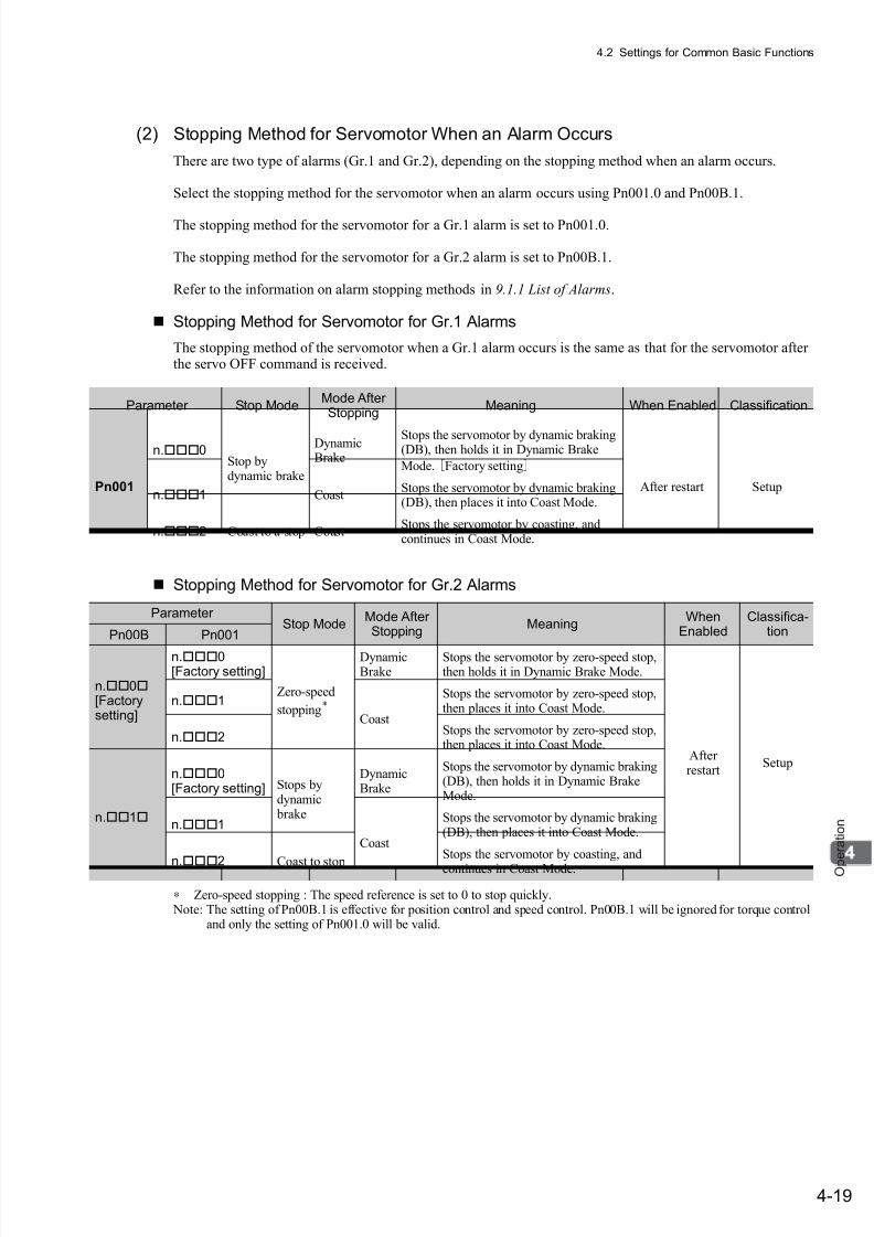
7/17/2019 Manual Yaskawa_servo_drive.pdf
http://slidepdf.com/reader/full/manual-yaskawaservodrivepdf 102/328
4.2 Settings for Common Basic Functions
4-19
O p e r a t i o n
(2) Stopping Method for Servomotor When an Alarm Occurs
There are two type of alarms (Gr.1 and Gr.2), depending on the stopping method when an alarm occurs.
Select the stopping method for the servomotor when an alarm occurs using Pn001.0 and Pn00B.1.
The stopping method for the servomotor for a Gr.1 alarm is set to Pn001.0.
The stopping method for the servomotor for a Gr.2 alarm is set to Pn00B.1.
Refer to the information on alarm stopping methods in 9.1.1 List of Alarms.
Stopping Method for Servomotor for Gr.1 Alarms
The stopping method of the servomotor when a Gr.1 alarm occurs is the same as that for the servomotor afterthe servo OFF command is received.
Stopping Method for Servomotor for Gr.2 Alarms
∗ Zero-speed stopping : The speed reference is set to 0 to stop quickly. Note: The setting of Pn00B.1 is effective for position control and speed control. Pn00B.1 will be ignored for torque control
and only the setting of Pn001.0 will be valid.
Parameter Stop ModeMode AfterStopping
Meaning When Enabled Classification
Pn001
n.0Stop bydynamic brake
DynamicBrake
Stops the servomotor by dynamic braking(DB), then holds it in Dynamic Brake
Mode. [Factory setting]
After restart Setupn.1 Coast
Stops the servomotor by dynamic braking(DB), then places it into Coast Mode.
n.2 Coast to a stop CoastStops the servomotor by coasting, andcontinues in Coast Mode.
Parameter Stop Mode
Mode After Stopping
MeaningWhen
EnabledClassifica-
tionPn00B Pn001
n.0[Factorysetting]
n.0[Factory setting]
Zero-speed
stopping*
DynamicBrake
Stops the servomotor by zero-speed stop,then holds it in Dynamic Brake Mode.
After restart
Setup
n.1
Coast
Stops the servomotor by zero-speed stop,then places it into Coast Mode.
n.2Stops the servomotor by zero-speed stop,then places it into Coast Mode.
n.1
n.0[Factory setting] Stops by
dynamic brake
DynamicBrake
Stops the servomotor by dynamic braking(DB), then holds it in Dynamic BrakeMode.
n.1
Coast
Stops the servomotor by dynamic braking(DB), then places it into Coast Mode.
n.
2 Coast to stop
Stops the servomotor by coasting, and
continues in Coast Mode.
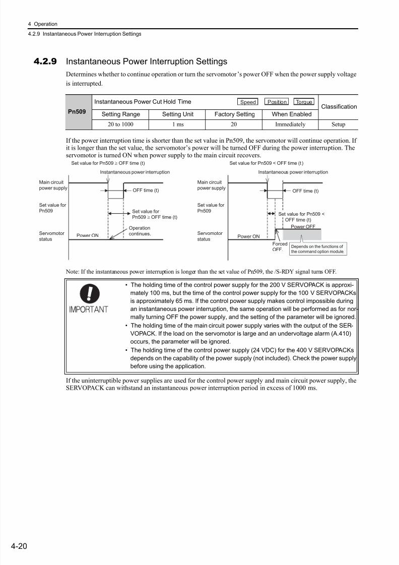
7/17/2019 Manual Yaskawa_servo_drive.pdf
http://slidepdf.com/reader/full/manual-yaskawaservodrivepdf 103/328
4 Operation
4.2.9 Instantaneous Power Interruption Settings
4-20
4.2.9 Instantaneous Power Interruption Settings
Determines whether to continue operation or turn the servomotor’s power OFF when the power supply voltage
is interrupted.
If the power interruption time is shorter than the set value in Pn509, the servomotor will continue operation. Ifit is longer than the set value, the servomotor’s power will be turned OFF during the power interruption. Theservomotor is turned ON when power supply to the main circuit recovers.
Note: If the instantaneous power interruption is longer than the set value of Pn509, the /S-RDY signal turns OFF.
If the uninterruptible power supplies are used for the control power supply and main circuit power supply, theSERVOPACK can withstand an instantaneous power interruption period in excess of 1000 ms.
Pn509
Instantaneous Power Cut Hold TimeClassification
Setting Range Setting Unit Factory Setting When Enabled
20 to 1000 1 ms 20 Immediately Setup
• The holding time of the control power supply for the 200 V SERVOPACK is approxi-
mately 100 ms, but the time of the control power supply for the 100 V SERVOPACKs
is approximately 65 ms. If the control power supply makes control impossible during
an instantaneous power interruption, the same operation will be performed as for nor-
mally turning OFF the power supply, and the setting of the parameter will be ignored.
• The holding time of the main circuit power supply varies with the output of the SER-
VOPACK. If the load on the servomotor is large and an undervoltage alarm (A.410)
occurs, the parameter will be ignored.
• The holding time of the control power supply (24 VDC) for the 400 V SERVOPACKs
depends on the capability of the power supply (not included). Check the power supply
before using the application.
Speed Position Torque
Instantaneous power interruption
Set value for Pn509 ≥ OFF time (t)
OFF time (t)
Power OFF
Set value for
Pn509 ≥ OFF time (t)Set value for Pn509 <
OFF time (t)
Main circuit
power supply
Set value for
Pn509
Servomotor
statusPower ON
Instantaneous power interruption
Set value for Pn509 < OFF time (t )
Forced
OFF.
OFF time (t)
Main circuit
power supply
Set value for
Pn509
Servomotor
statusPower ON
Operation
continues.
Depends on the functions of
the command option module.
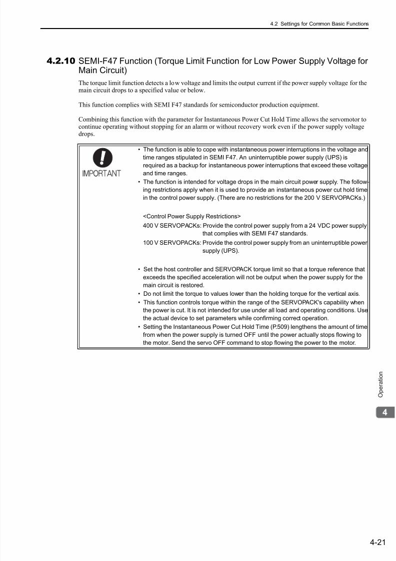
7/17/2019 Manual Yaskawa_servo_drive.pdf
http://slidepdf.com/reader/full/manual-yaskawaservodrivepdf 104/328
4.2 Settings for Common Basic Functions
4-21
O p e r a t i o n
4.2.10 SEMI-F47 Function (Torque Limit Function for Low Power Supply Voltage forMain Circuit)
The torque limit function detects a low voltage and limits the output current if the power supply voltage for themain circuit drops to a specified value or below.
This function complies with SEMI F47 standards for semiconductor production equipment.
Combining this function with the parameter for Instantaneous Power Cut Hold Time allows the servomotor tocontinue operating without stopping for an alarm or without recovery work even if the power supply voltagedrops.
• The function is able to cope with instantaneous power interruptions in the voltage and
time ranges stipulated in SEMI F47. An uninterruptible power supply (UPS) is
required as a backup for instantaneous power interruptions that exceed these voltage
and time ranges.
• The function is intended for voltage drops in the main circuit power supply. The follow-
ing restrictions apply when it is used to provide an instantaneous power cut hold time
in the control power supply. (There are no restrictions for the 200 V SERVOPACKs.)
<Control Power Supply Restrictions>
400 V SERVOPACKs: Provide the control power supply from a 24 VDC power supply
that complies with SEMI F47 standards.
100 V SERVOPACKs: Provide the control power supply from an uninterruptible power
supply (UPS).
• Set the host controller and SERVOPACK torque limit so that a torque reference that
exceeds the specified acceleration will not be output when the power supply for the
main circuit is restored.
• Do not limit the torque to values lower than the holding torque for the vertical axis.• This function controls torque within the range of the SERVOPACK's capability when
the power is cut. It is not intended for use under all load and operating conditions. Use
the actual device to set parameters while confirming correct operation.
• Setting the Instantaneous Power Cut Hold Time (P.509) lengthens the amount of time
from when the power supply is turned OFF until the power actually stops flowing to
the motor. Send the servo OFF command to stop flowing the power to the motor.

7/17/2019 Manual Yaskawa_servo_drive.pdf
http://slidepdf.com/reader/full/manual-yaskawaservodrivepdf 105/328
4 Operation
4.2.10 SEMI-F47 Function (Torque Limit Function for Low Power Supply Voltage for Main Circuit)
4-22
(1) Execution Method
This function can be executed either with the host controller or independently with the SERVOPACK.Pn008.1 is used to specify whether the function is executed with the host controller or independently with theSERVOPACK.
Execution with Host Controller (Pn008=n.1)
The host controller limits the torque in response to a low-voltage warning.The torque is no longer limited when the low-voltage warning is cleared.
Execution Independently with SERVOPACK (Pn008=n.2)
The torque is limited in the SERVOPACK in response to a low-voltage warning.The SERVOPACK stops limiting the torque in the set time (Pn425) when the low-voltage warning is cleared.
Main circuit power interruption timeMain circuit
input supply
Main circuit
bus voltage
Low-voltage
warning detected
Torque limit
reference
280 V*1
200 V*2
Low-voltage
warning
Torque limit
SERVOPACK
Hostcontroller
Torque limit starts.
0%
0%
Torque limit ends.
Setting value for Pn425
Setting value for Pn424
Main circuit bus voltageincreases by recoveryof the main circuit power.
The bus voltage drops slowly becauseoutput torque is limited.
The torque is limited inresponse to a low-voltage warning.
*1 560 V for 400 V power supply.
*2 400 V for 400 V power supply.
280 V*1
200 V*2
0%
Main circuit power interruption time
Main circuit
input supply
Main circuit
bus voltage
Low-voltage
warning detected Torque limit starts.
Setting value for Pn424
Setting value for Pn425
Torque limit
SERVOPACK
Main circuit bus voltageincreases by recoveryof the main circuit power.
The bus voltage drops slowly becauseoutput torque is limited.
*1 560 V for 400 V power supply.
*2 400 V for 400 V power supply.

7/17/2019 Manual Yaskawa_servo_drive.pdf
http://slidepdf.com/reader/full/manual-yaskawaservodrivepdf 106/328
4.2 Settings for Common Basic Functions
4-23
O p e r a t i o n
(2) Related Parameters
∗ The setting unit is a percentage of the rated torque.
Note: When using SEMI F47 function, set 1000 ms.
Parameter Meaning When Enabled Classification
Pn008
n.0A main circuit low voltage is not detected.
[Factory setting]
After restart Setupn.1
A main circuit low voltage is detected, and the hostcontroller limits the torque.
n.2A main circuit low voltage is detected, and the SER-VOPACK independently limits the torque usingPn424 and Pn425.
Torque Limit at Main Circuit Voltage Drop Classification
Pn424 Setting Range Setting Unit Factory Setting When Enabled
0 to 100 1% ∗ 50 Immediately Setup
Release Time for Torque Limit at MainCircuit Voltage Drop
ClassificationPn425 Setting Range Setting Unit Factory Setting When Enabled
0 to 1000 1 ms 100 Immediately Setup
Pn509
Instantaneous Power Cut Hold TimeClassification
Setting Range Setting Unit Factory Setting When Enabled
20 to 1000 1 ms 20 Immediately Setup
Speed Position Torque
Speed Position Torque
Speed Position Torque
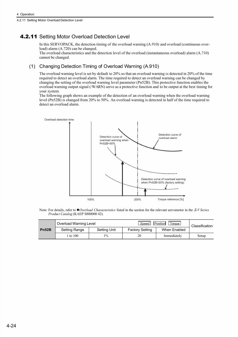
7/17/2019 Manual Yaskawa_servo_drive.pdf
http://slidepdf.com/reader/full/manual-yaskawaservodrivepdf 107/328
4 Operation
4.2.11 Setting Motor Overload Detection Level
4-24
4.2.11 Setting Motor Overload Detection Level
In this SERVOPACK, the detection timing of the overload warning (A.910) and overload (continuous over-load) alarm (A.720) can be changed.The overload characteristics and the detection level of the overload (instantaneous overload) alarm (A.710)
cannot be changed.
(1) Changing Detection Timing of Overload Warning (A.910)
The overload warning level is set by default to 20% so that an overload warning is detected in 20% of the timerequired to detect an overload alarm. The time required to detect an overload warning can be changed bychanging the setting of the overload warning level parameter (Pn52B). This protective function enables theoverload warning output signal (/WARN) serve as a protective function and to be output at the best timing foryour system.The following graph shows an example of the detection of an overload warning when the overload warninglevel (Pn52B) is changed from 20% to 50%. An overload warning is detected in half of the time required todetect an overload alarm.
Note: For details, refer toOverload Characteristics listed in the section for the relevant servomotor in the Σ -V Series Product Catalog (KAEP S800000 42).
Overload Warning Level Classification
Pn52B Setting Range Setting Unit Factory Setting When Enabled
1 to 100 1% 20 Immediately Setup
200%100%
Overload detection time
Detection curve of
overload alarm
Detection curve of overload warning
when Pn52B=20% (factory setting)
Detection curve of
overload warning when
Pn52B=50%
Torque reference [%]
Speed Position Torque

7/17/2019 Manual Yaskawa_servo_drive.pdf
http://slidepdf.com/reader/full/manual-yaskawaservodrivepdf 108/328
4.2 Settings for Common Basic Functions
4-25
O p e r a t i o n
(2) Changing Detection Timing of Overload Alarm (A.720)
An overload alarm (continuous overload) can be detected earlier to protect the motor from overloading. Thetime required to detect an overload alarm can be shortened by using the derated motor base current obtainedwith the following equation. The detection level of the overload (instantaneous overload) alarm (A.710) can-
not be changed.
Motor base current × Derating of base current at detecting overload of motor (Pn52C)= Derated motor base current
Motor base current: Threshold value of motor current to start calculation for overload alarmDerating of base current at detecting overload of motor (Pn52C): Derating of motor base current
The following graph shows an example of the detection of an overload alarm when Pn52C is set to 50%. Thecalculation for the overload alarm of motors starts at 50% of the motor base current and then an overloadalarm will be detected earlier.Changing the setting of Pn52C will change the detection timing of the overload alarm, so the time required todetect the overload warning will also be changed.
As a guideline of motor heating conditions, the relationship between the heat sink sizes and deratings of basecurrent is shown in a graph in:Servomotor Heating Conditions in Rotary Servomotors General Instruction in Σ -V Series Product Catalog (KAEP S800000 42).Set Pn52C to a value in accordance with the heat sink size and derating shown in the graph, so that an over-load alarm can be detected at the best timing to protect the motor from overloading.
Note: For details, refer toOverload Characteristics listed in the section for the relevant servomotor in the Σ -V Series Product Catalog (KAEP S800000 42).
Pn52C
Derating of Base Current at Detecting Overload of Motor Classification
Setting Range Setting Unit Factory Setting When Enabled
10 to 100 1% 100 After restart Setup
Detection curve of
overload alarm when
Pn52C=100% (factory setting)
Detection curve of
overload alarm
when Pn52C=50%
Torque reference [%]50%
Overload detection time
100% 200%
Speed Position Torque
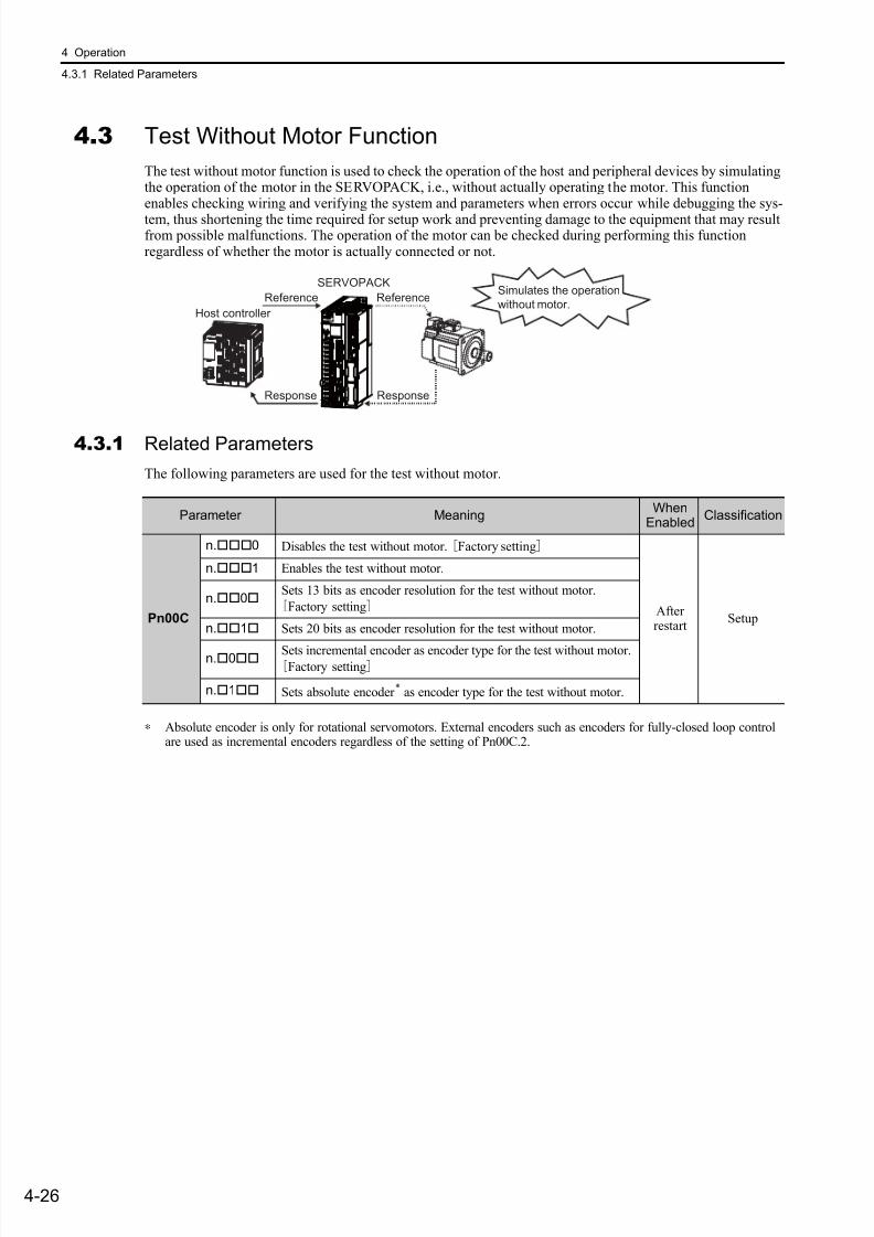
7/17/2019 Manual Yaskawa_servo_drive.pdf
http://slidepdf.com/reader/full/manual-yaskawaservodrivepdf 109/328
4 Operation
4.3.1 Related Parameters
4-26
4.3 Test Without Motor Function
The test without motor function is used to check the operation of the host and peripheral devices by simulatingthe operation of the motor in the SERVOPACK, i.e., without actually operating the motor. This functionenables checking wiring and verifying the system and parameters when errors occur while debugging the sys-
tem, thus shortening the time required for setup work and preventing damage to the equipment that may resultfrom possible malfunctions. The operation of the motor can be checked during performing this functionregardless of whether the motor is actually connected or not.
4.3.1 Related Parameters
The following parameters are used for the test without motor.
∗ Absolute encoder is only for rotational servomotors. External encoders such as encoders for fully-closed loop controlare used as incremental encoders regardless of the setting of Pn00C.2.
Reference Reference
ResponseResponse
Host controller
SERVOPACKSimulates the operation
without motor.
Parameter MeaningWhen
EnabledClassification
Pn00C
n.0 Disables the test without motor. [Factory setting]
Afterrestart
Setup
n.1 Enables the test without motor.
n.0Sets 13 bits as encoder resolution for the test without motor.
[Factory setting]
n.1 Sets 20 bits as encoder resolution for the test without motor.
n.0 Sets incremental encoder as encoder type for the test without motor.[Factory setting]
n.1 Sets absolute encoder * as encoder type for the test without motor.
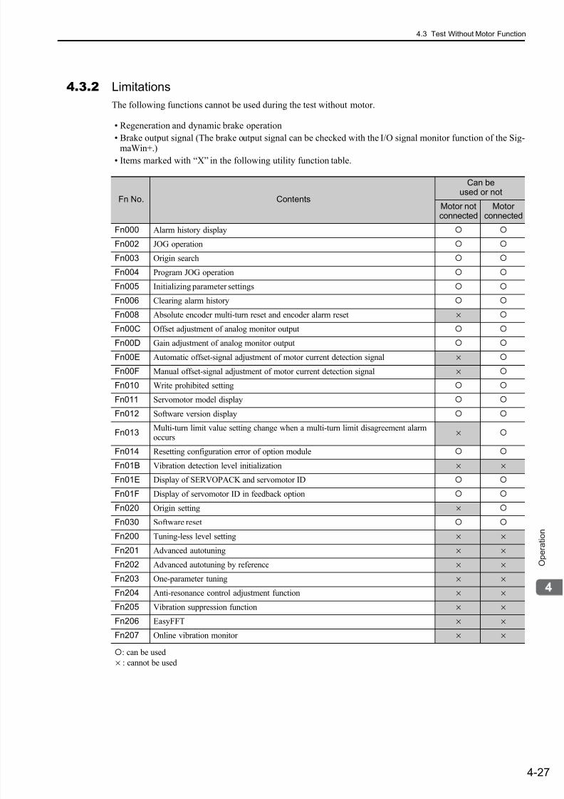
7/17/2019 Manual Yaskawa_servo_drive.pdf
http://slidepdf.com/reader/full/manual-yaskawaservodrivepdf 110/328
4.3 Test Without Motor Function
4-27
O p e r a t i o n
4.3.2 Limitations
The following functions cannot be used during the test without motor.
• Regeneration and dynamic brake operation
• Brake output signal (The brake output signal can be checked with the I/O signal monitor function of the Sig-maWin+.)
• Items marked with “X” in the following utility function table.
: can be used
× : cannot be used
Fn No. Contents
Can beused or not
Motor notconnected
Motorconnected
Fn000 Alarm history display
Fn002 JOG operation
Fn003 Origin search
Fn004 Program JOG operation
Fn005 Initializing parameter settings
Fn006 Clearing alarm history
Fn008 Absolute encoder multi-turn reset and encoder alarm reset ×
Fn00C Offset adjustment of analog monitor output
Fn00D Gain adjustment of analog monitor output
Fn00E Automatic offset-signal adjustment of motor current detection signal ×
Fn00F Manual offset-signal adjustment of motor current detection signal ×
Fn010 Write prohibited setting
Fn011 Servomotor model display
Fn012 Software version display
Fn013Multi-turn limit value setting change when a multi-turn limit disagreement alarmoccurs
×
Fn014 Resetting configuration error of option module
Fn01B Vibration detection level initialization × ×
Fn01E Display of SERVOPACK and servomotor ID
Fn01F Display of servomotor ID in feedback option
Fn020 Origin setting ×
Fn030 Software reset
Fn200 Tuning-less level setting × ×
Fn201 Advanced autotuning × ×
Fn202 Advanced autotuning by reference × ×
Fn203 One-parameter tuning × ×
Fn204 Anti-resonance control adjustment function × ×
Fn205 Vibration suppression function × ×
Fn206 EasyFFT × ×
Fn207 Online vibration monitor × ×
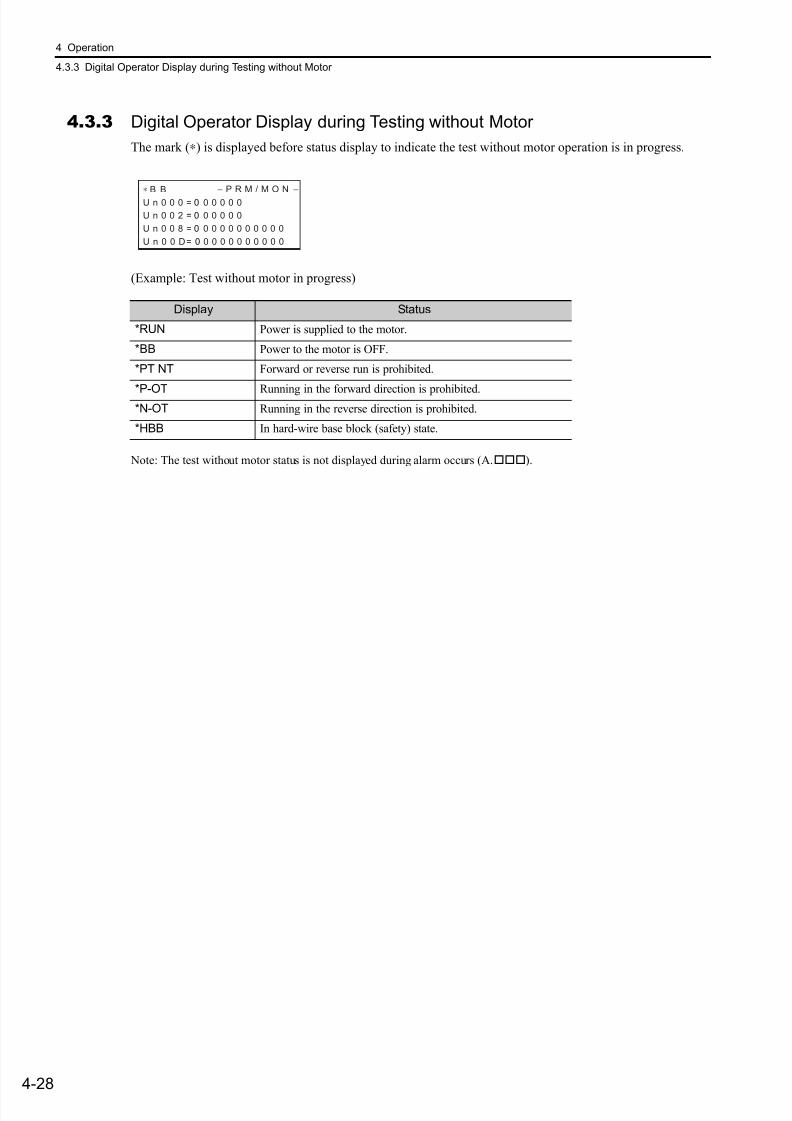
7/17/2019 Manual Yaskawa_servo_drive.pdf
http://slidepdf.com/reader/full/manual-yaskawaservodrivepdf 111/328
4 Operation
4.3.3 Digital Operator Display during Testing without Motor
4-28
4.3.3 Digital Operator Display during Testing without Motor
The mark (∗) is displayed before status display to indicate the test without motor operation is in progress.
(Example: Test without motor in progress)
Note: The test without motor status is not displayed during alarm occurs (A.).
Display Status
*RUN Power is supplied to the motor.
*BB Power to the motor is OFF.
*PT NT Forward or reverse run is prohibited.
*P-OT Running in the forward direction is prohibited.*N-OT Running in the reverse direction is prohibited.
*HBB In hard-wire base block (safety) state.
∗ B B − P R M / M O N −
U n 0 0 0 = 0 0 0 0 0 0
U n 0 0 2 = 0 0 0 0 0 0
U n 0 0 8 = 0 0 0 0 0 0 0 0 0 0 0
U n 0 0 D = 0 0 0 0 0 0 0 0 0 0 0

7/17/2019 Manual Yaskawa_servo_drive.pdf
http://slidepdf.com/reader/full/manual-yaskawaservodrivepdf 112/328
4.4 Limiting Torque
4-29
O p e r a t i o n
4.4 Limiting Torque
The SERVOPACK provides the following three methods for limiting output torque to protect the machine.
4.4.1 Internal Torque Limit
This function always limits maximum output torque by setting values of following parameters.
The setting unit is a percentage of the rated torque.
Note 1. Too small a torque limit setting will result in insufficient torque during acceleration and deceleration.2. The maximum torque of the servomotor is used whenever the value exceeds the maximum torque is set.
Waveform of Torque
Limiting Method DescriptionReference
Section
Internal torque limit Always limits torque by setting the parameter. 4.4.1
External torque limit Limits torque by input signal from the host controller. 4.4.2
Torque limit with commandoption module
Limits torque by inputting a desired torque limit command to thecommand option module from the host controller.
Refer to the manualof the commandoption module to be connected.
Pn402
Forward Torque LimitClassification
Setting Range Setting Unit Factory Setting When Enabled
0 to 800 1% 800 Immediately Setup
Pn403
Reverse Torque LimitClassification
Setting Range Setting Unit Factory Setting When Enabled
0 to 800 1% 800 Immediately Setup
Speed Position Torque
Speed Position Torque
Speed
Maximum torque
t
Speed
Pn403
Pn402
Limiting torque
t
No Internal Torque Limit
(Maximum Torque Can Be Output)Internal Torque Limit
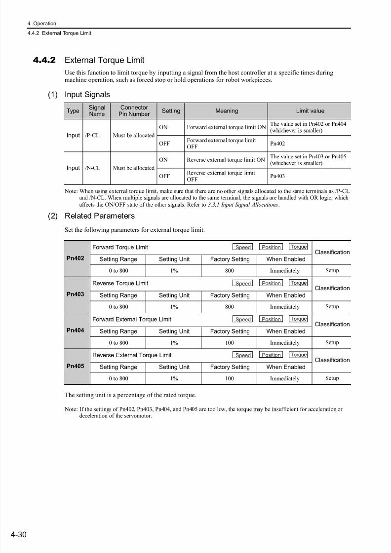
7/17/2019 Manual Yaskawa_servo_drive.pdf
http://slidepdf.com/reader/full/manual-yaskawaservodrivepdf 113/328
4 Operation
4.4.2 External Torque Limit
4-30
4.4.2 External Torque Limit
Use this function to limit torque by inputting a signal from the host controller at a specific times duringmachine operation, such as forced stop or hold operations for robot workpieces.
(1) Input Signals
Note: When using external torque limit, make sure that there are no other signals allocated to the same terminals as /P-CLand /N-CL. When multiple signals are allocated to the same terminal, the signals are handled with OR logic, which
affects the ON/OFF state of the other signals. Refer to 3.3.1 Input Signal Allocations.
(2) Related Parameters
Set the following parameters for external torque limit.
The setting unit is a percentage of the rated torque.
Note: If the settings of Pn402, Pn403, Pn404, and Pn405 are too low, the torque may be insufficient for acceleration ordeceleration of the servomotor.
TypeSignalName
Connector Pin Number
Setting Meaning Limit value
Input /P-CL Must be allocated
ON Forward external torque limit ONThe value set in Pn402 or Pn404(whichever is smaller)
OFFForward external torque limitOFF
Pn402
Input /N-CL Must be allocated
ON Reverse external torque limit ONThe value set in Pn403 or Pn405(whichever is smaller)
OFFReverse external torque limitOFF
Pn403
Pn402
Forward Torque LimitClassification
Setting Range Setting Unit Factory Setting When Enabled
0 to 800 1% 800 Immediately Setup
Pn403
Reverse Torque Limit
ClassificationSetting Range Setting Unit Factory Setting When Enabled
0 to 800 1% 800 Immediately Setup
Pn404
Forward External Torque LimitClassification
Setting Range Setting Unit Factory Setting When Enabled
0 to 800 1% 100 Immediately Setup
Pn405
Reverse External Torque LimitClassification
Setting Range Setting Unit Factory Setting When Enabled
0 to 800 1% 100 Immediately Setup
Speed Position Torque
Speed Position Torque
Speed Position Torque
Speed Position Torque
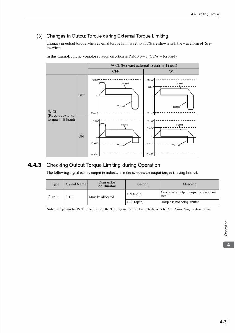
7/17/2019 Manual Yaskawa_servo_drive.pdf
http://slidepdf.com/reader/full/manual-yaskawaservodrivepdf 114/328
4.4 Limiting Torque
4-31
O p e r a t i o n
(3) Changes in Output Torque during External Torque Limiting
Changes in output torque when external torque limit is set to 800% are shown with the waveform of Sig-maWin+.
In this example, the servomotor rotation direction is Pn000.0 = 0 (CCW = forward).
4.4.3 Checking Output Torque Limiting during Operation
The following signal can be output to indicate that the servomotor output torque is being limited.
Note: Use parameter Pn50F.0 to allocate the /CLT signal for use. For details, refer to 3.3.2 Output Signal Allocation.
/P-CL (Forward external torque limit input)
OFF ON
/N-CL
(Reverse externaltorque limit input)
OFF
ON
Pn402
Pn403
0
Torque
Speed
Pn403
0
Pn404
Pn402
Torque
Speed
0
Pn403
Pn405
Pn402
Torque
Speed
0
Pn403
Pn405
Pn404
Pn402
Torque
Speed
Type Signal NameConnector
Pin Number Setting Meaning
Output /CLT Must be allocatedON (close)
Servomotor output torque is being lim-ited.
OFF (open) Torque is not being limited.
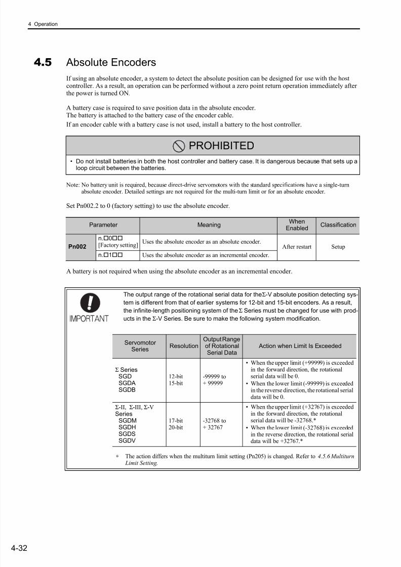
7/17/2019 Manual Yaskawa_servo_drive.pdf
http://slidepdf.com/reader/full/manual-yaskawaservodrivepdf 115/328
4 Operation
4-32
4.5 Absolute Encoders
If using an absolute encoder, a system to detect the absolute position can be designed for use with the hostcontroller. As a result, an operation can be performed without a zero point return operation immediately afterthe power is turned ON.
A battery case is required to save position data in the absolute encoder.The battery is attached to the battery case of the encoder cable.
If an encoder cable with a battery case is not used, install a battery to the host controller.
Note: No battery unit is required, because direct-drive servomotors with the standard specifications have a single-turnabsolute encoder. Detailed settings are not required for the multi-turn limit or for an absolute encoder.
Set Pn002.2 to 0 (factory setting) to use the absolute encoder.
A battery is not required when using the absolute encoder as an incremental encoder.
PROHIBITED
• Do not install batteries in both the host controller and battery case. It is dangerous because that sets up aloop circuit between the batteries.
Parameter MeaningWhen
EnabledClassification
Pn002
n.0[Factory setting]
Uses the absolute encoder as an absolute encoder.After restart Setup
n.1 Uses the absolute encoder as an incremental encoder.
The output range of the rotational serial data for the Σ-V absolute position detecting sys-
tem is different from that of earlier systems for 12-bit and 15-bit encoders. As a result,
the infinite-length positioning system of the Σ Series must be changed for use with prod-
ucts in the Σ-V Series. Be sure to make the following system modification.
∗ The action differs when the multiturn limit setting (Pn205) is changed. Refer to 4.5.6 Multiturn Limit Setting .
ServomotorSeries
ResolutionOutput Rangeof RotationalSerial Data
Action when Limit Is Exceeded
Σ Series SGD SGDA SGDB
12-bit15-bit
-99999 to+ 99999
• When the upper limit (+99999) is exceededin the forward direction, the rotationalserial data will be 0.
• When the lower limit (-99999) is exceededin the reverse direction, the rotational serial
data will be 0.
Σ-II, Σ-III, Σ-V Series SGDM SGDH SGDS SGDV
17-bit20-bit
-32768 to+ 32767
• When the upper limit (+32767) is exceededin the forward direction, the rotationalserial data will be -32768.*
• When the lower limit (-32768) is exceededin the reverse direction, the rotational serialdata will be +32767.*
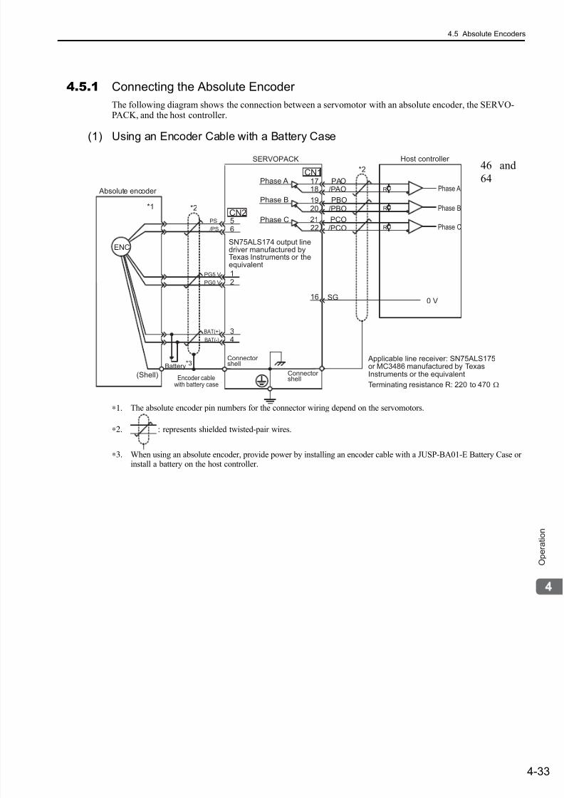
7/17/2019 Manual Yaskawa_servo_drive.pdf
http://slidepdf.com/reader/full/manual-yaskawaservodrivepdf 116/328
4.5 Absolute Encoders
4-33
O p e r a t i o n
4.5.1 Connecting the Absolute Encoder
The following diagram shows the connection between a servomotor with an absolute encoder, the SERVO-PACK, and the host controller.
(1) Using an Encoder Cable with a Battery Case
∗1. The absolute encoder pin numbers for the connector wiring depend on the servomotors.
∗2. : represents shielded twisted-pair wires.
∗3. When using an absolute encoder, provide power by installing an encoder cable with a JUSP-BA01-E Battery Case orinstall a battery on the host controller.
/PCO
ENC
34
CN2
1718
1920
2122
CN1
SG16
PAO/P AO
PBO/PBO
PCO
Absolute encoder
(Shell)
Battery*3
SERVOPACK
Phase A
Phase B
Phase C
Connectorshell
Connectorshell
*2
*2*1
0 V
Host controller
56
1
2PG5 V
PG0 V
PS
/PS
BAT(+)
BAT(-)
Phase A
Phase B
Phase C
R
R
R
Applicable line receiver: SN75ALS175or MC3486 manufactured by TexasInstruments or the equivalent
Terminating resistance R: 220 to 470 ΩEncoder cable
with battery case
SN75ALS174 output linedriver manufactured byTexas Instruments or theequivalent
46 and
64
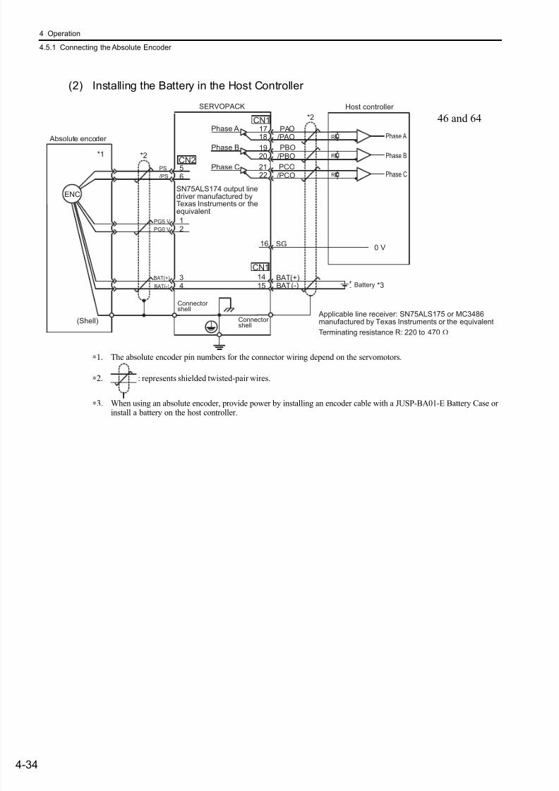
7/17/2019 Manual Yaskawa_servo_drive.pdf
http://slidepdf.com/reader/full/manual-yaskawaservodrivepdf 117/328
4 Operation
4.5.1 Connecting the Absolute Encoder
4-34
(2) Installing the Battery in the Host Controller
∗1. The absolute encoder pin numbers for the connector wiring depend on the servomotors.
∗2. : represents shielded twisted-pair wires.
∗3. When using an absolute encoder, provide power by installing an encoder cable with a JUSP-BA01-E Battery Case or
install a battery on the host controller.
/PCO
ENC
34
1415
BATBAT
(+)(-)
CN2
17
181920
2122
CN1
SG16
PAO
/P AOPBO
/PBO
PCO
Absolute encoder
(Shell)
SERVOPACK
Phase A
Phase B
Phase C
Connectorshell
Connectorshell
CN1
*2
*3
*2*1
0 V
Host controller
+- Battery
56
12
PG5 V
PG0 V
PS
/PS
BAT(+)
BAT(-)
Phase A
Phase B
Phase C
R
R
R
Applicable line receiver: SN75ALS175 or MC3486manufactured by Texas Instruments or the equivalent
Terminating resistance R: 220 to 470 Ω
SN75ALS174 output linedriver manufactured byTexas Instruments or theequivalent
46 and 64
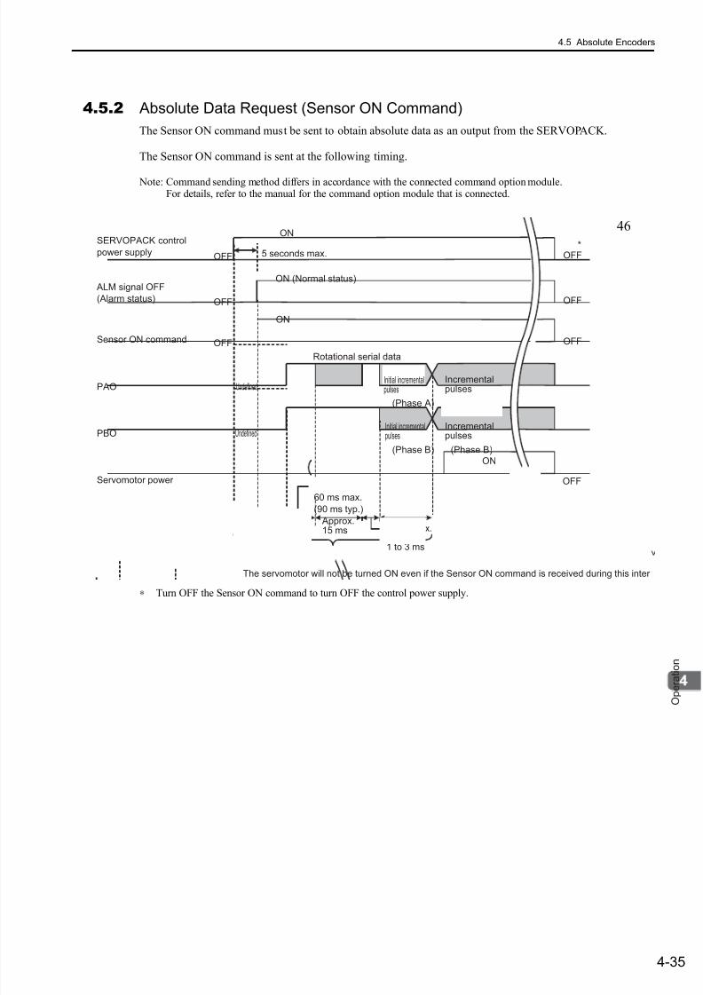
7/17/2019 Manual Yaskawa_servo_drive.pdf
http://slidepdf.com/reader/full/manual-yaskawaservodrivepdf 118/328
4.5 Absolute Encoders
4-35
O p e r a t i o n
4.5.2 Absolute Data Request (Sensor ON Command)
The Sensor ON command must be sent to obtain absolute data as an output from the SERVOPACK.
The Sensor ON command is sent at the following timing.
Note: Command sending method differs in accordance with the connected command option module.For details, refer to the manual for the command option module that is connected.
∗ Turn OFF the Sensor ON command to turn OFF the control power supply.
SERVOPACK control
power supply 5 seconds max.
ON
OFF
OFF
ON (Normal status)
OFF
ON
50 ms
Rotational serial data
(Phase A)
(Phase B) (Phase B)
Approx.15 ms 400 ms max.
1 to 3 ms
60 ms max.
(90 ms typ.)
The servomotor will not be turned ON even if the Sensor ON command is received during this inter
ALM signal OFF
(Alarm status)
Sensor ON command
PAO
PBO
Servomotor power
Undefined
Undefined
(Phase A)
OFF
OFF
OFF
OFF
*
ON
Incrementalpulses
Incrementalpulses
Initial incrementalpulses
Initial incrementalpulses
46

7/17/2019 Manual Yaskawa_servo_drive.pdf
http://slidepdf.com/reader/full/manual-yaskawaservodrivepdf 119/328
4 Operation
4.5.3 Battery Replacement
4-36
4.5.3 Battery Replacement
If the battery voltage drops to approximately 2.7 V, an absolute encoder battery error (A.830) or absoluteencoder battery warning (A.930) will be displayed.
If an alarm or warning is displayed, replace the battery using the following procedure.
Use Pn008 to set either an alarm (A.830) or a warning (A.930).
• If Pn008.0 is set to 0, an ALM signal is sent for a maximum of 5 seconds, and then the battery voltage ischecked for 4 seconds when the power is turned ON.
Note: After those initial 4 second, no alarm will be displayed even if the battery voltage drops to approximately 2.7 V.
• If Pn008.0 is set to 1, the battery voltage will constantly be monitored.
(1) Battery Replacement Procedure
Using an Encoder Cable with a Battery Case
1. Turn ON only the SERVOPACK control power supply.
2. Open the battery case cover. (Example: cable with battery and connectors at both ends)
Parameter Meaning When Enabled Classification
Pn008
n.0Outputs the alarm A.830 when the battery voltage
drops. [Factory setting]After restart Setup
n.1Outputs the warning A.930 when the battery voltagedrops.
4 sMax 5 s
Warning A.930(Pn008.0 = 1)
Alarm A.830
(Pn008.0 = 0)
ALM
OFF (close)
Alarm status Normal status
ON (open)
Batteryvoltage being
monitored
Battery voltage
being monitored
Controlpower
Open the cover.
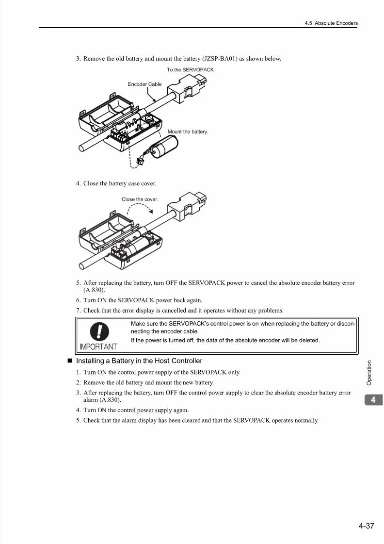
7/17/2019 Manual Yaskawa_servo_drive.pdf
http://slidepdf.com/reader/full/manual-yaskawaservodrivepdf 120/328
4.5 Absolute Encoders
4-37
O p e r a t i o n
3. Remove the old battery and mount the battery (JZSP-BA01) as shown below.
4. Close the battery case cover.
5. After replacing the battery, turn OFF the SERVOPACK power to cancel the absolute encoder battery error(A.830).
6. Turn ON the SERVOPACK power back again.
7. Check that the error display is cancelled and it operates without any problems.
Installing a Battery in the Host Controller
1. Turn ON the control power supply of the SERVOPACK only.
2. Remove the old battery and mount the new battery.
3. After replacing the battery, turn OFF the control power supply to clear the absolute encoder battery erroralarm (A.830).
4. Turn ON the control power supply again.
5. Check that the alarm display has been cleared and that the SERVOPACK operates normally.
Make sure the SERVOPACK’s control power is on when replacing the battery or discon-
necting the encoder cable.
If the power is turned off, the data of the absolute encoder will be deleted.
Mount the battery.
To the SERVOPACK
Encoder Cable
Close the cover.
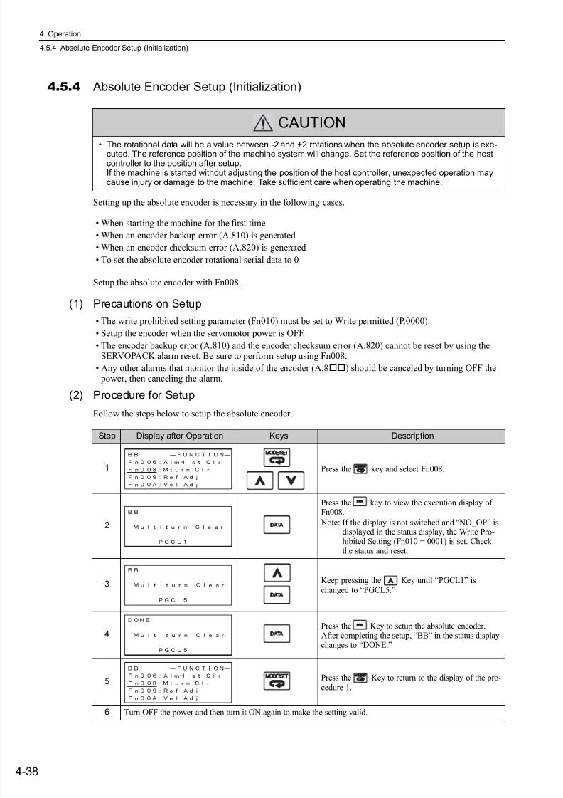
7/17/2019 Manual Yaskawa_servo_drive.pdf
http://slidepdf.com/reader/full/manual-yaskawaservodrivepdf 121/328
4 Operation
4.5.4 Absolute Encoder Setup (Initialization)
4-38
4.5.4 Absolute Encoder Setup (Initialization)
Setting up the absolute encoder is necessary in the following cases.
• When starting the machine for the first time
• When an encoder backup error (A.810) is generated
• When an encoder checksum error (A.820) is generated
• To set the absolute encoder rotational serial data to 0
Setup the absolute encoder with Fn008.
(1) Precautions on Setup
• The write prohibited setting parameter (Fn010) must be set to Write permitted (P.0000).
• Setup the encoder when the servomotor power is OFF.
• The encoder backup error (A.810) and the encoder checksum error (A.820) cannot be reset by using theSERVOPACK alarm reset. Be sure to perform setup using Fn008.
• Any other alarms that monitor the inside of the encoder (A.8) should be canceled by turning OFF the power, then canceling the alarm.
(2) Procedure for Setup
Follow the steps below to setup the absolute encoder.
CAUTION
• The rotational data will be a value between -2 and +2 rotations when the absolute encoder setup is exe-cuted. The reference position of the machine system will change. Set the reference position of the hostcontroller to the position after setup.If the machine is started without adjusting the position of the host controller, unexpected operation maycause injury or damage to the machine. Take sufficient care when operating the machine.
Step Display after Operation Keys Description
1 Press the key and select Fn008.
2
Press the key to view the execution display ofFn008.
Note: If the display is not switched and “NO_OP” isdisplayed in the status display, the Write Pro-hibited Setting (Fn010 = 0001) is set. Checkthe status and reset.
3 Keep pressing the Key until “PGCL1” ischanged to “PGCL5.”
4Press the Key to setup the absolute encoder.After completing the setup, “BB” in the status displaychanges to “DONE.”
5 Press the Key to return to the display of the pro-cedure 1.
6 Turn OFF the power and then turn it ON again to make the setting valid.
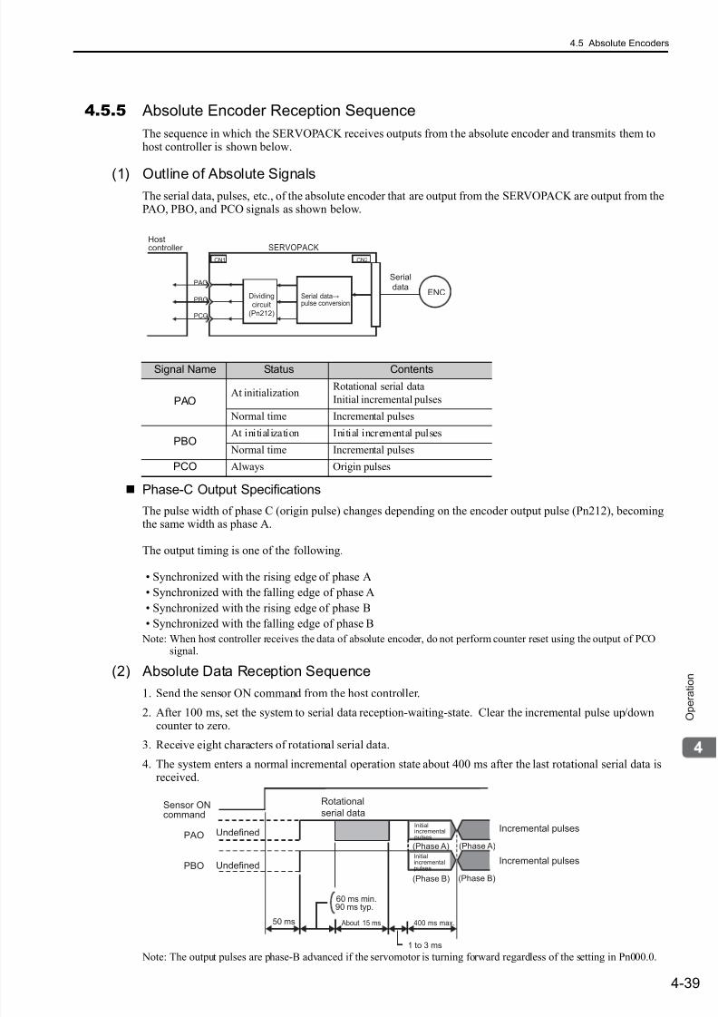
7/17/2019 Manual Yaskawa_servo_drive.pdf
http://slidepdf.com/reader/full/manual-yaskawaservodrivepdf 122/328
4.5 Absolute Encoders
4-39
O p e r a t i o n
4.5.5 Absolute Encoder Reception Sequence
The sequence in which the SERVOPACK receives outputs from the absolute encoder and transmits them tohost controller is shown below.
(1) Outline of Absolute SignalsThe serial data, pulses, etc., of the absolute encoder that are output from the SERVOPACK are output from thePAO, PBO, and PCO signals as shown below.
Phase-C Output Specifications
The pulse width of phase C (origin pulse) changes depending on the encoder output pulse (Pn212), becomingthe same width as phase A.
The output timing is one of the following.
• Synchronized with the rising edge of phase A
• Synchronized with the falling edge of phase A
• Synchronized with the rising edge of phase B
• Synchronized with the falling edge of phase B
Note: When host controller receives the data of absolute encoder, do not perform counter reset using the output of PCOsignal.
(2) Absolute Data Reception Sequence
1. Send the sensor ON command from the host controller.
2. After 100 ms, set the system to serial data reception-waiting-state. Clear the incremental pulse up/downcounter to zero.
3. Receive eight characters of rotational serial data.
4. The system enters a normal incremental operation state about 400 ms after the last rotational serial data isreceived.
Note: The output pulses are phase-B advanced if the servomotor is turning forward regardless of the setting in Pn000.0.
Signal Name Status Contents
PAOAt initialization
Rotational serial data
Initial incremental pulses
Normal time Incremental pulses
PBOAt initialization Initial incremental pulses
Normal time Incremental pulses
PCO Always Origin pulses
ENC
CN1
PAO
PBO
PCO
CN2
Serial
dataSerial data→pulse conversion
Hostcontroller SERVOPACK
Dividing
circuit
(Pn212)
Sensor ONcommand
PAO
PBO
Incremental pulses
Incremental pulsesUndefined
Undefined
(Phase A) (Phase A)
(Phase B) (Phase B)
Rotational
serial data
400 ms max.50 ms
1 to 3 ms
About 15 ms
90 ms typ.60 ms min.
Initialincrementalpulses
Initialincrementalpulses
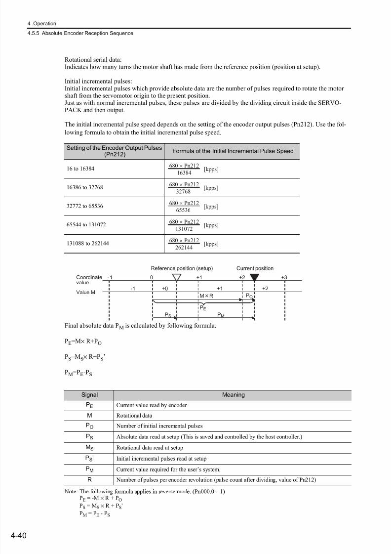
7/17/2019 Manual Yaskawa_servo_drive.pdf
http://slidepdf.com/reader/full/manual-yaskawaservodrivepdf 123/328
4 Operation
4.5.5 Absolute Encoder Reception Sequence
4-40
Rotational serial data:Indicates how many turns the motor shaft has made from the reference position (position at setup).
Initial incremental pulses:Initial incremental pulses which provide absolute data are the number of pulses required to rotate the motor
shaft from the servomotor origin to the present position.Just as with normal incremental pulses, these pulses are divided by the dividing circuit inside the SERVO-PACK and then output.
The initial incremental pulse speed depends on the setting of the encoder output pulses (Pn212). Use the fol-
lowing formula to obtain the initial incremental pulse speed.
Final absolute data PM is calculated by following formula.
PE=M× R+PO
PS=MS× R+PS’
PM=PE-PS
Note: The following formula applies in reverse mode. (Pn000.0 = 1)PE = -M × R + PO
PS = MS × R + PS'
PM = PE - PS
Setting of the Encoder Output Pulses(Pn212)
Formula of the Initial Incremental Pulse Speed
16 to 16384
16386 to 32768
32772 to 65536
65544 to 131072
131088 to 262144
680 × Pn212
16384 [kpps]
680 × Pn212
32768
[kpps]
680 × Pn212
65536[kpps]
680 × Pn212
131072 [kpps]
680 × Pn212
262144 [kpps]
Coordinatevalue
Value M
Reference position (setup)
-1 0 +1 +2 +3
+2
Current position
+1±0-1
PE
PMPS
POMR
Signal Meaning
PE Current value read by encoder
M Rotational data
PO Number of initial incremental pulses
PS Absolute data read at setup (This is saved and controlled by the host controller.)
MS Rotational data read at setup
PS’ Initial incremental pulses read at setup
PM Current value required for the user’s system.
R Number of pulses per encoder revolution (pulse count after dividing, value of Pn212)
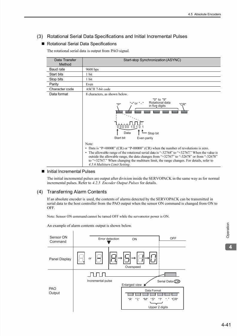
7/17/2019 Manual Yaskawa_servo_drive.pdf
http://slidepdf.com/reader/full/manual-yaskawaservodrivepdf 124/328
4.5 Absolute Encoders
4-41
O p e r a t i o n
(3) Rotational Serial Data Specifications and Initial Incremental Pulses
Rotational Serial Data Specifications
The rotational serial data is output from PAO signal.
Initial Incremental Pulses
The initial incremental pulses are output after division inside the SERVOPACK in the same way as for normalincremental pulses. Refer to 4.2.5 Encoder Output Pulses for details.
(4) Transferring Alarm Contents
If an absolute encoder is used, the contents of alarms detected by the SERVOPACK can be transmitted inserial data to the host controller from the PAO output when the sensor ON command is changed from ON toOFF.
Note: Sensor ON command cannot be turned OFF while the servomotor power is ON.
An example of alarm contents output is shown below.
Data TransferMethod
Start-stop Synchronization (ASYNC)
Baud rate 9600 bps
Start bits 1 bit
Stop bits 1 bit
Parity Even
Character code ASCII 7-bit code
Data format 8 characters, as shown below.
Note:
• Data is “P+00000” (CR) or “P-00000” (CR) when the number of revolutions is zero.
• The allowable range of the rotational serial data is “-32768” to “+32767.” When the value isoutside the allowable range, the data changes from “+32767” to “-32678” or from “-32678”to “+32767.” When changing the multiturn limit, the range changes. For details, refer to4.5.6 Multiturn Limit Setting .
Data
Start bit Even parity
Rotational datain five digits
"+" or " - ""0" to "9"
"CR""P"
Stop bit
0 0 0 0 0 1 0 1 0 1
CR
Sensor ON
CommandOFFError detection ON
Incremental pulse Serial DataEnlarged view
Panel Display
PAO
Output
Data Format
Upper 2 digits
A L M 5 1 . CR" " " " " " " " " " " " " "
or
Overspeed
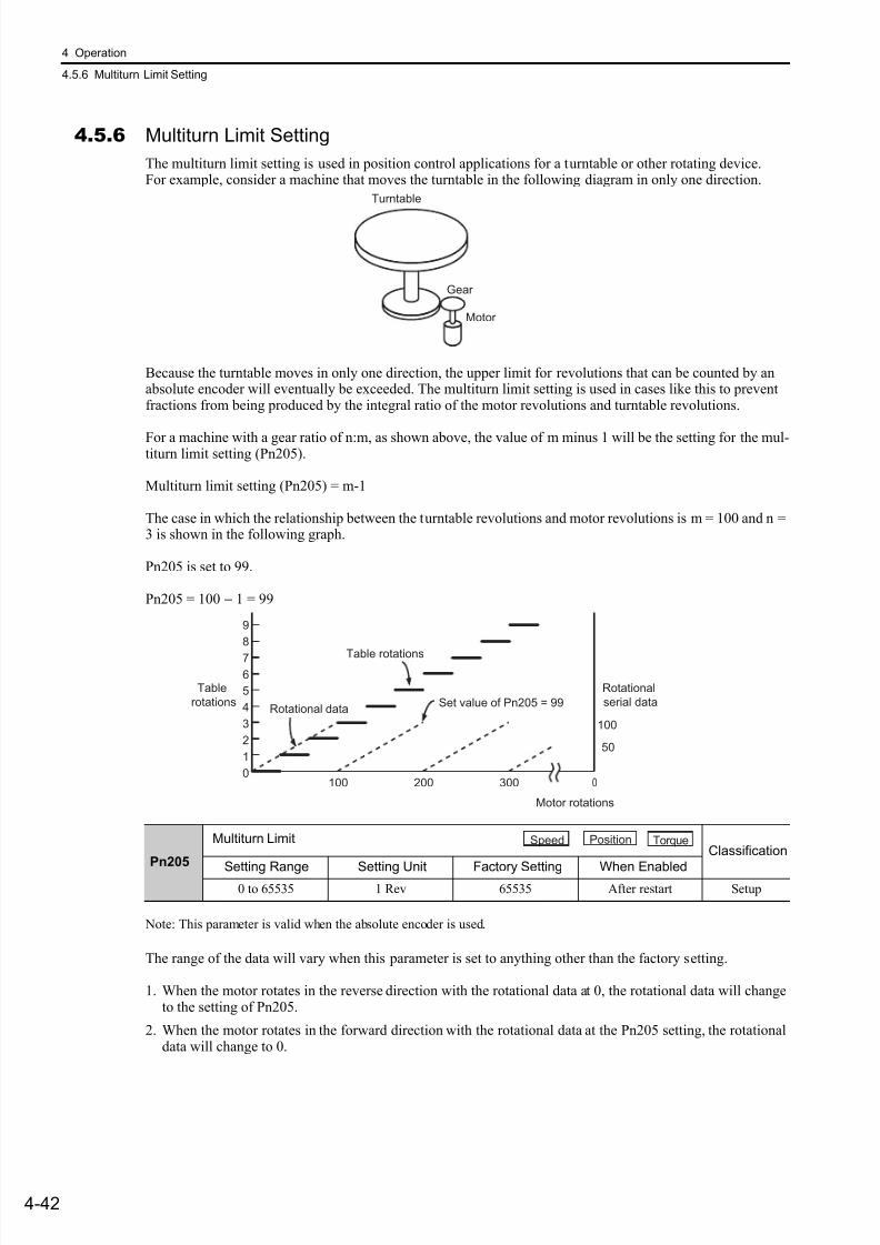
7/17/2019 Manual Yaskawa_servo_drive.pdf
http://slidepdf.com/reader/full/manual-yaskawaservodrivepdf 125/328
4 Operation
4.5.6 Multiturn Limit Setting
4-42
4.5.6 Multiturn Limit Setting
The multiturn limit setting is used in position control applications for a turntable or other rotating device.For example, consider a machine that moves the turntable in the following diagram in only one direction.
Because the turntable moves in only one direction, the upper limit for revolutions that can be counted by anabsolute encoder will eventually be exceeded. The multiturn limit setting is used in cases like this to preventfractions from being produced by the integral ratio of the motor revolutions and turntable revolutions.
For a machine with a gear ratio of n:m, as shown above, the value of m minus 1 will be the setting for the mul-titurn limit setting (Pn205).
Multiturn limit setting (Pn205) = m-1
The case in which the relationship between the turntable revolutions and motor revolutions is m = 100 and n =3 is shown in the following graph.
Pn205 is set to 99.
Pn205 = 100 − 1 = 99
Note: This parameter is valid when the absolute encoder is used.
The range of the data will vary when this parameter is set to anything other than the factory setting.
1. When the motor rotates in the reverse direction with the rotational data at 0, the rotational data will changeto the setting of Pn205.
2. When the motor rotates in the forward direction with the rotational data at the Pn205 setting, the rotationaldata will change to 0.
Pn205
Multiturn LimitClassification
Setting Range Setting Unit Factory Setting When Enabled0 to 65535 1 Rev 65535 After restart Setup
Turntable
Gear
Motor
0
1
2
3
4
5
6
7
8
9
Motor rotations
100 200 300 0
100
50
Rotational data
Table rotations
Set value of Pn205 = 99
Table
rotations
Rotational
serial data
Speed Position Torque
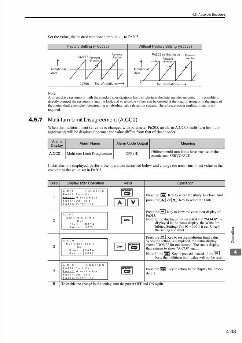
7/17/2019 Manual Yaskawa_servo_drive.pdf
http://slidepdf.com/reader/full/manual-yaskawaservodrivepdf 126/328
4.5 Absolute Encoders
4-43
O p
e r a t i o n
Set the value, the desired rotational amount -1, to Pn205.
Note:A direct-drive servomotor with the standard specifications has a single-turn absolute encoder mounted. It is possible todirectly connect the servomotor and the load, and so absolute values can be created at the load by using only the angle ofthe motor shaft even when constructing an absolute value detection system. Therefore, encoder multiturn data is notrequired.
4.5.7 Multi-turn Limit Disagreement (A.CC0)When the multiturn limit set value is changed with parameter Pn205, an alarm A.CC0 (multi-turn limit dis-agreement) will be displayed because the value differs from that of the encoder.
If this alarm is displayed, perform the operation described below and change the multi-turn limit value in theencoder to the value set in Pn205
Factory Setting (= 65535) Without Factory Setting (≠65535)
+32767
-32768 No. of rotations
Rotational
data0
ReversedirectionForward
direction
0
Pn205 setting value Reversedirection
No. of rotations
Forwarddirection
Rotational
data
AlarmDisplay
Alarm Name Alarm Code Output Meaning
A.CC0 Multi-turn Limit Disagreement OFF (H)Different multi-turn limits have been set in theencoder and SERVOPACK.
Step Display after Operation Keys Operation
1Press the Key to select the utility function. And
press the or Key to select the Fn013.
2
Press the Key to view the execution display ofFn013. Note: If the display is not switched and “NO-OP” is
displayed in the status display, the Write Pro-hibited Setting (Fn010 = 0001) is set. Checkthe setting and reset.
3
Press the Key to set the multiturn limit value.
When the setting is completed, the status displayshows "DONE" for one second. The status displaythen returns to show "A.CC0" again.
Note: If the Key is pressed instead of theKey, the multiturn limit value will not be reset.
4 Press the Key to return to the display the proce-dure 1.
5 To enable the change in the setting, turn the power OFF and ON again.
A . C C 0
F n 0 1 2 : S o f t V e r
F n 0 1 3 : M t u r n L m S e t
F n 0 1 4 : O p t I n i t
F n 0 1 B : V i b l v l I n i t
- F U N C T I O N -
A . C C 0
M u l t i t u r n L i m i t
S e t
S t a r t : [ D A T A ]
R e t u r n : [ S E T ]
A . C C 0 M u l t i t u r n L i m i t
S e t
S t a r t : [ D A T A ]
R e t u r n : [ S E T ]
A . C C 0
F n 0 1 2 : S o f t V e r
F n 0 1 3 : M t u r n L m S e t
F n 0 1 4 : O p t I n i t
F n 0 1 B : V i b l v l I n i t
- F U N C T I O N -
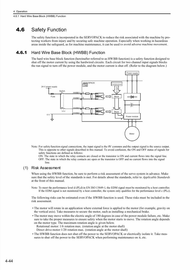
7/17/2019 Manual Yaskawa_servo_drive.pdf
http://slidepdf.com/reader/full/manual-yaskawaservodrivepdf 127/328
4 Operation
4.6.1 Hard Wire Base Block (HWBB) Function
4-44
4.6 Safety Function
The safety function is incorporated in the SERVOPACK to reduce the risk associated with the machine by pro-tecting workers from injury and by securing safe machine operation. Especially when working in hazardousareas inside the safeguard, as for machine maintenance, it can be used to avoid adverse machine movement.
4.6.1 Hard Wire Base Block (HWBB) Function
The hard wire base block function (hereinafter referred to as HWBB function) is a safety function designed toshut off the motor current by using the hardwired circuits: Each circuit for two channel input signals blocksthe run signal to turn off the power module, and the motor current is shut off. (Refer to the diagram below.)
Note: For safety function signal connections, the input signal is the 0V common and the output signal is the source output.This is opposite to other signals described in this manual. To avoid confusion, the ON and OFF status of signals forsafety functions are defined as follows:ON: The state in which the relay contacts are closed or the transistor is ON and current flows into the signal line.OFF: The state in which the relay contacts are open or the transistor is OFF and no current flows into the signal line.
(1) Risk Assessment
When using the HWBB function, be sure to perform a risk assessment of the servo system in advance. Makesure that the safety level of the standards is met. For details about the standards, refer to Applicable Standards at the front of this manual.
Note: To meet the performance level d (PLd) in EN ISO 13849-1, the EDM signal must be monitored by a host controller.If the EDM signal is not monitored by a host controller, the system only qualifies for the performance level c (PLc).
The following risks can be estimated even if the HWBB function is used. These risks must be included in therisk assessment.
• The motor will rotate in an application where external force is applied to the motor (for example, gravity onthe vertical axis). Take measures to secure the motor, such as installing a mechanical brake.
• The motor may move within the electric angle of 180 degrees in case of the power module failure, etc. Makesure to take the proper measures to ensure safety when the motor starts to move. The rotation angle dependson the motor type. The maximum rotation angle is given below. Rotational motor: 1/6 rotation max. (rotation angle at the motor shaft) Direct drive motor:1/20 rotation max. (rotation angle at the motor shaft)
• The HWBB function does not shut off the power to the SERVOPACK or electrically isolate it. Take mea-
sures to shut off the power to the SERVOPACK when performing maintenance on it, etc.
6
5
/HWBB2+
/HWBB2-
4
3
CN8
/HWBB1+
/HWBB1-
0 V
Control circuitSERVOPACK
Switch
Block
Block
Power module
Power supply
24-V power supply
Fuse
Motor
R u n s i g n a l
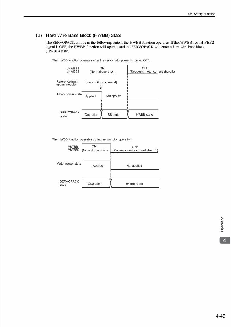
7/17/2019 Manual Yaskawa_servo_drive.pdf
http://slidepdf.com/reader/full/manual-yaskawaservodrivepdf 128/328
4.6 Safety Function
4-45
O p
e r a t i o n
(2) Hard Wire Base Block (HWBB) State
The SERVOPACK will be in the following state if the HWBB function operates. If the /HWBB1 or /HWBB2signal is OFF, the HWBB function will operate and the SERVOPACK will enter a hard wire base block(HWBB) state.
/HWBB1/HWBB2
Reference fromoption module
Motor power stateNot applied
(Normal operation) (Requests motor current shutoff.)
(Normal operation) (Requests motor current shutoff.)
Applied Not applied
/HWBB1/HWBB2
Motor power state
[Servo OFF command]
SERVOPACK
state
ON OFF
HWBB stateBB stateOperation
SERVOPACK
state
ON OFF
HWBB stateOperation
The HWBB function operates after the servomotor power is turned OFF.
The HWBB function operates during servomotor operation.
Applied
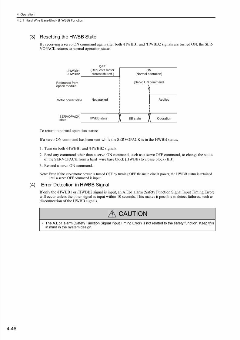
7/17/2019 Manual Yaskawa_servo_drive.pdf
http://slidepdf.com/reader/full/manual-yaskawaservodrivepdf 129/328
4 Operation
4.6.1 Hard Wire Base Block (HWBB) Function
4-46
(3) Resetting the HWBB State
By receiving a servo ON command again after both /HWBB1 and /HWBB2 signals are turned ON, the SER-VOPACK returns to normal operation status.
To return to normal operation status:
If a servo ON command has been sent while the SERVOPACK is in the HWBB status,
1. Turn on both /HWBB1 and /HWBB2 signals.
2. Send any command other than a servo ON command, such as a servo OFF command, to change the statusof the SERVOPACK from a hard wire base block (HWBB) to a base block (BB).
3. Resend a servo ON command.
Note: Even if the servomotor power is turned OFF by turning OFF the main circuit power, the HWBB status is retained
until a servo OFF command is input.
(4) Error Detection in HWBB Signal
If only the /HWBB1 or /HWBB2 signal is input, an A.Eb1 alarm (Safety Function Signal Input Timing Error)will occur unless the other signal is input within 10 seconds. This makes it possible to detect failures, such asdisconnection of the HWBB signals.
/HWBB1/HWBB2
Motor power state AppliedNot applied
(Normal operation)
(Requests motor
current shutoff.)
Reference fromoption module
[Servo ON command]
OFFON
SERVOPACKstate HWBB state BB state Operation
CAUTION
• The A.Eb1 alarm (Safety Function Signal Input Timing Error) is not related to the safety function. Keep thisin mind in the system design.
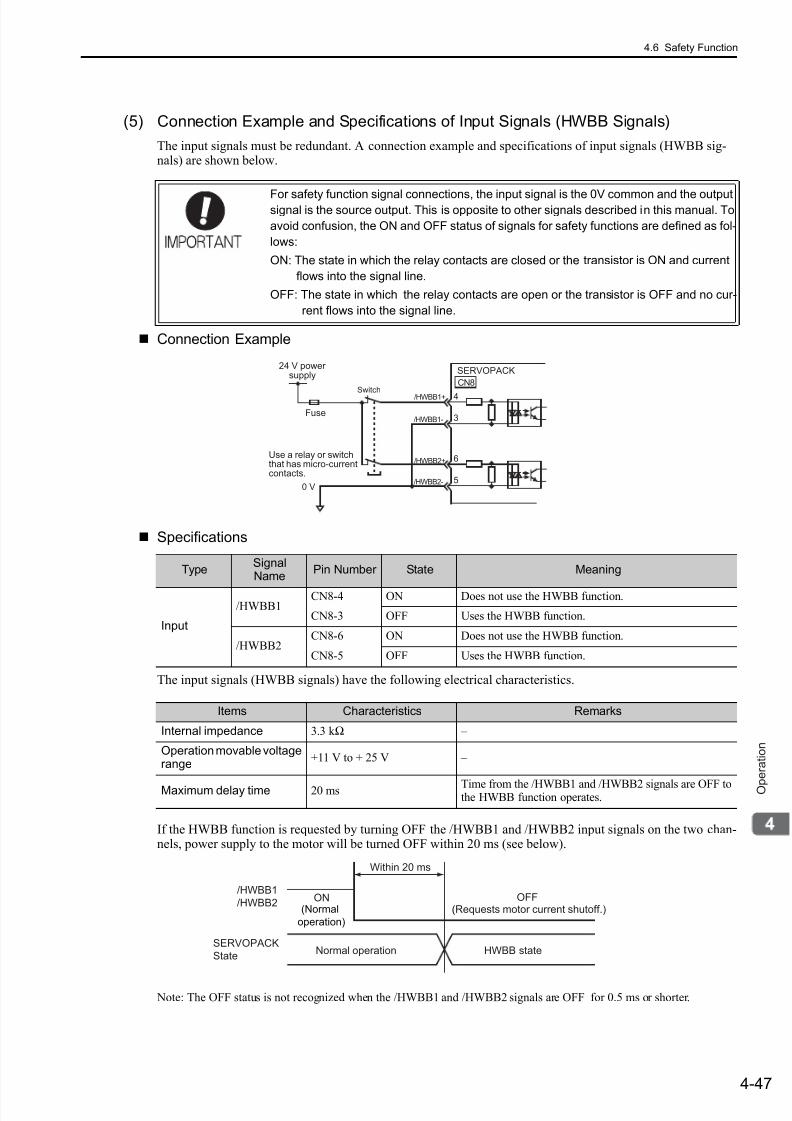
7/17/2019 Manual Yaskawa_servo_drive.pdf
http://slidepdf.com/reader/full/manual-yaskawaservodrivepdf 130/328
4.6 Safety Function
4-47
O p
e r a t i o n
(5) Connection Example and Specifications of Input Signals (HWBB Signals)
The input signals must be redundant. A connection example and specifications of input signals (HWBB sig-nals) are shown below.
Connection Example
Specifications
The input signals (HWBB signals) have the following electrical characteristics.
If the HWBB function is requested by turning OFF the /HWBB1 and /HWBB2 input signals on the two chan-nels, power supply to the motor will be turned OFF within 20 ms (see below).
Note: The OFF status is not recognized when the /HWBB1 and /HWBB2 signals are OFF for 0.5 ms or shorter.
For safety function signal connections, the input signal is the 0V common and the outputsignal is the source output. This is opposite to other signals described in this manual. To
avoid confusion, the ON and OFF status of signals for safety functions are defined as fol-
lows:
ON: The state in which the relay contacts are closed or the transistor is ON and current
flows into the signal line.
OFF: The state in which the relay contacts are open or the transistor is OFF and no cur-
rent flows into the signal line.
TypeSignalName
Pin Number State Meaning
Input
/HWBB1CN8-4 ON Does not use the HWBB function.
CN8-3 OFF Uses the HWBB function.
/HWBB2CN8-6 ON Does not use the HWBB function.
CN8-5 OFF Uses the HWBB function.
0 V
CN8
24 V powersupply
Fuse
SERVOPACK
Use a relay or switchthat has micro-currentcontacts.
6
5
/HWBB2+
/HWBB2-
4
3
/HWBB1+
/HWBB1-
Switch
Items Characteristics Remarks
Internal impedance 3.3 k Ω –
Operation movable voltagerange
+11 V to + 25 V –
Maximum delay time 20 ms Time from the /HWBB1 and /HWBB2 signals are OFF tothe HWBB function operates.
/HWBB1
/HWBB2
Normal operationSERVOPACK
StateHWBB state
Within 20 ms
(Normal
operation)
(Requests motor current shutoff.)OFFON
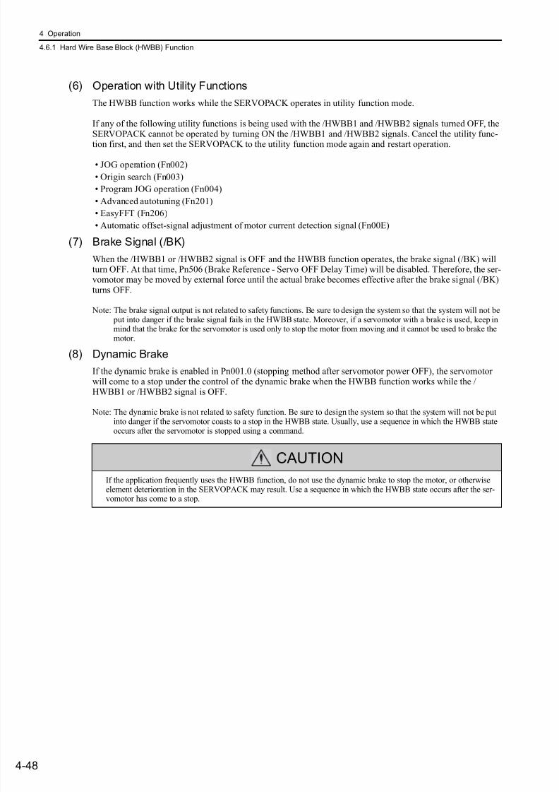
7/17/2019 Manual Yaskawa_servo_drive.pdf
http://slidepdf.com/reader/full/manual-yaskawaservodrivepdf 131/328
4 Operation
4.6.1 Hard Wire Base Block (HWBB) Function
4-48
(6) Operation with Utility Functions
The HWBB function works while the SERVOPACK operates in utility function mode.
If any of the following utility functions is being used with the /HWBB1 and /HWBB2 signals turned OFF, the
SERVOPACK cannot be operated by turning ON the /HWBB1 and /HWBB2 signals. Cancel the utility func-tion first, and then set the SERVOPACK to the utility function mode again and restart operation.
• JOG operation (Fn002)
• Origin search (Fn003)
• Program JOG operation (Fn004)
• Advanced autotuning (Fn201)
• EasyFFT (Fn206)
• Automatic offset-signal adjustment of motor current detection signal (Fn00E)
(7) Brake Signal (/BK)
When the /HWBB1 or /HWBB2 signal is OFF and the HWBB function operates, the brake signal (/BK) willturn OFF. At that time, Pn506 (Brake Reference - Servo OFF Delay Time) will be disabled. Therefore, the ser-
vomotor may be moved by external force until the actual brake becomes effective after the brake signal (/BK)turns OFF.
Note: The brake signal output is not related to safety functions. Be sure to design the system so that the system will not be put into danger if the brake signal fails in the HWBB state. Moreover, if a servomotor with a brake is used, keep inmind that the brake for the servomotor is used only to stop the motor from moving and it cannot be used to brake themotor.
(8) Dynamic Brake
If the dynamic brake is enabled in Pn001.0 (stopping method after servomotor power OFF), the servomotorwill come to a stop under the control of the dynamic brake when the HWBB function works while the /HWBB1 or /HWBB2 signal is OFF.
Note: The dynamic brake is not related to safety function. Be sure to design the system so that the system will not be putinto danger if the servomotor coasts to a stop in the HWBB state. Usually, use a sequence in which the HWBB stateoccurs after the servomotor is stopped using a command.
CAUTION
If the application frequently uses the HWBB function, do not use the dynamic brake to stop the motor, or otherwiseelement deterioration in the SERVOPACK may result. Use a sequence in which the HWBB state occurs after the ser-vomotor has come to a stop.
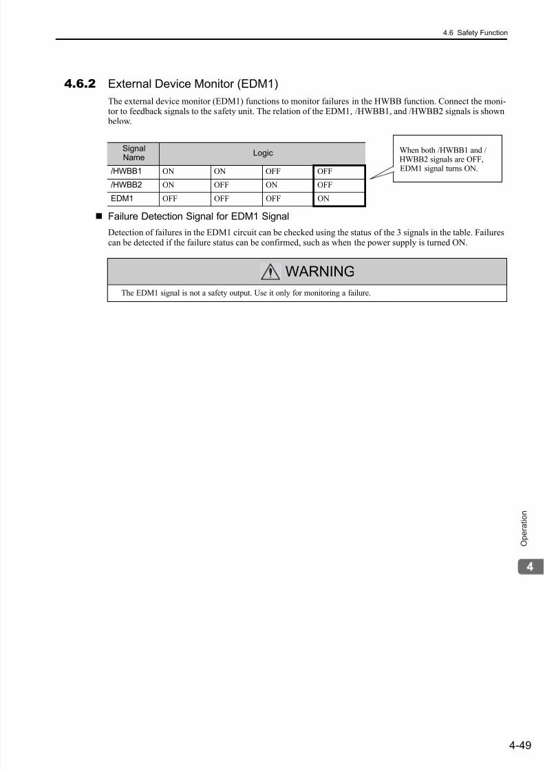
7/17/2019 Manual Yaskawa_servo_drive.pdf
http://slidepdf.com/reader/full/manual-yaskawaservodrivepdf 132/328
4.6 Safety Function
4-49
O p
e r a t i o n
4.6.2 External Device Monitor (EDM1)
The external device monitor (EDM1) functions to monitor failures in the HWBB function. Connect the moni-tor to feedback signals to the safety unit. The relation of the EDM1, /HWBB1, and /HWBB2 signals is shown
below.
Failure Detection Signal for EDM1 Signal
Detection of failures in the EDM1 circuit can be checked using the status of the 3 signals in the table. Failurescan be detected if the failure status can be confirmed, such as when the power supply is turned ON.
SignalName
Logic
/HWBB1 ON ON OFF OFF
/HWBB2 ON OFF ON OFF
EDM1 OFF OFF OFF ON
When both /HWBB1 and /HWBB2 signals are OFF,EDM1 signal turns ON.
WARNINGThe EDM1 signal is not a safety output. Use it only for monitoring a failure.
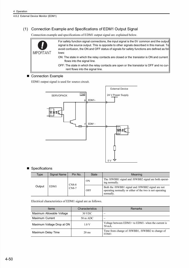
7/17/2019 Manual Yaskawa_servo_drive.pdf
http://slidepdf.com/reader/full/manual-yaskawaservodrivepdf 133/328
4 Operation
4.6.2 External Device Monitor (EDM1)
4-50
(1) Connection Example and Specifications of EDM1 Output Signal
Connection example and specifications of EDM1 output signal are explained below.
Connection Example
EDM1 output signal is used for source circuit.
Specifications
Electrical characteristics of EDM1 signal are as follows.
For safety function signal connections, the input signal is the 0V common and the output
signal is the source output. This is opposite to other signals described in this manual. To
avoid confusion, the ON and OFF status of signals for safety functions are defined as fol-
lows:
ON: The state in which the relay contacts are closed or the transistor is ON and current
flows into the signal line.
OFF: The state in which the relay contacts are open or the transistor is OFF and no cur-
rent flows into the signal line.
EDM1+
EDM1−
8
7
0 V
CN8 24 V Power SupplySERVOPACK
External Device
Type Signal Name Pin No. State Meaning
Output EDM1
CN8-8
CN8-7
ONThe /HWBB1 signal and /HWBB2 signal are both operat-ing normally.
OFFBoth the /HWBB1 signal and /HWBB2 signal are notoperating normally or either of the two is not operatingnormally.
Items Characteristics Remarks
Maximum Allowable Voltage 30 VDC −
Maximum Current 50 m ADC −
Maximum Voltage Drop at ON 1.0 VVoltage between EDM1+ to EDM1- when the current is50 mA.
Maximum Delay Time 20 msTime from change of /HWBB1, /HWBB2 to change of
EDM1
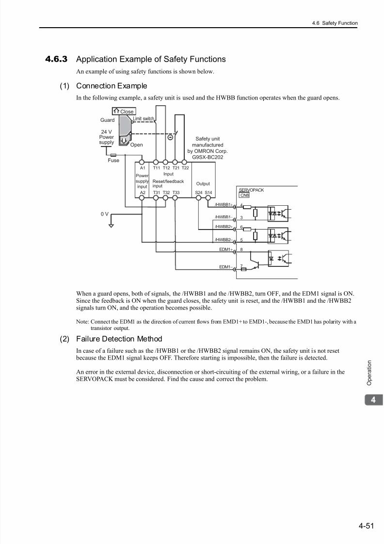
7/17/2019 Manual Yaskawa_servo_drive.pdf
http://slidepdf.com/reader/full/manual-yaskawaservodrivepdf 134/328
4.6 Safety Function
4-51
O p
e r a t i o n
4.6.3 Application Example of Safety Functions
An example of using safety functions is shown below.
(1) Connection Example
In the following example, a safety unit is used and the HWBB function operates when the guard opens.
When a guard opens, both of signals, the /HWBB1 and the /HWBB2, turn OFF, and the EDM1 signal is ON.Since the feedback is ON when the guard closes, the safety unit is reset, and the /HWBB1 and the /HWBB2signals turn ON, and the operation becomes possible.
Note: Connect the EDM1 as the direction of current flows from EMD1+ to EMD1-, because the EMD1 has polarity with atransistor output.
(2) Failure Detection Method
In case of a failure such as the /HWBB1 or the /HWBB2 signal remains ON, the safety unit is not reset because the EDM1 signal keeps OFF. Therefore starting is impossible, then the failure is detected.
An error in the external device, disconnection or short-circuiting of the external wiring, or a failure in the
SERVOPACK must be considered. Find the cause and correct the problem.
/HWBB1+ 4
3
6
5
8
7
A1
A2
T11 T12 T21
T31 T32 T33 S24 S14
T22
/HWBB1−
/HWBB2+
/HWBB2−
EDM1+
EDM1−
0 V
CN8SERVOPACK
Output
24 VPowersupply
Guard
Safety unit
manufactured
by OMRON Corp.
G9SX-BC202Fuse
Close
Limit switch
Power
supply
input
Input
Reset/feedbackinput
Open
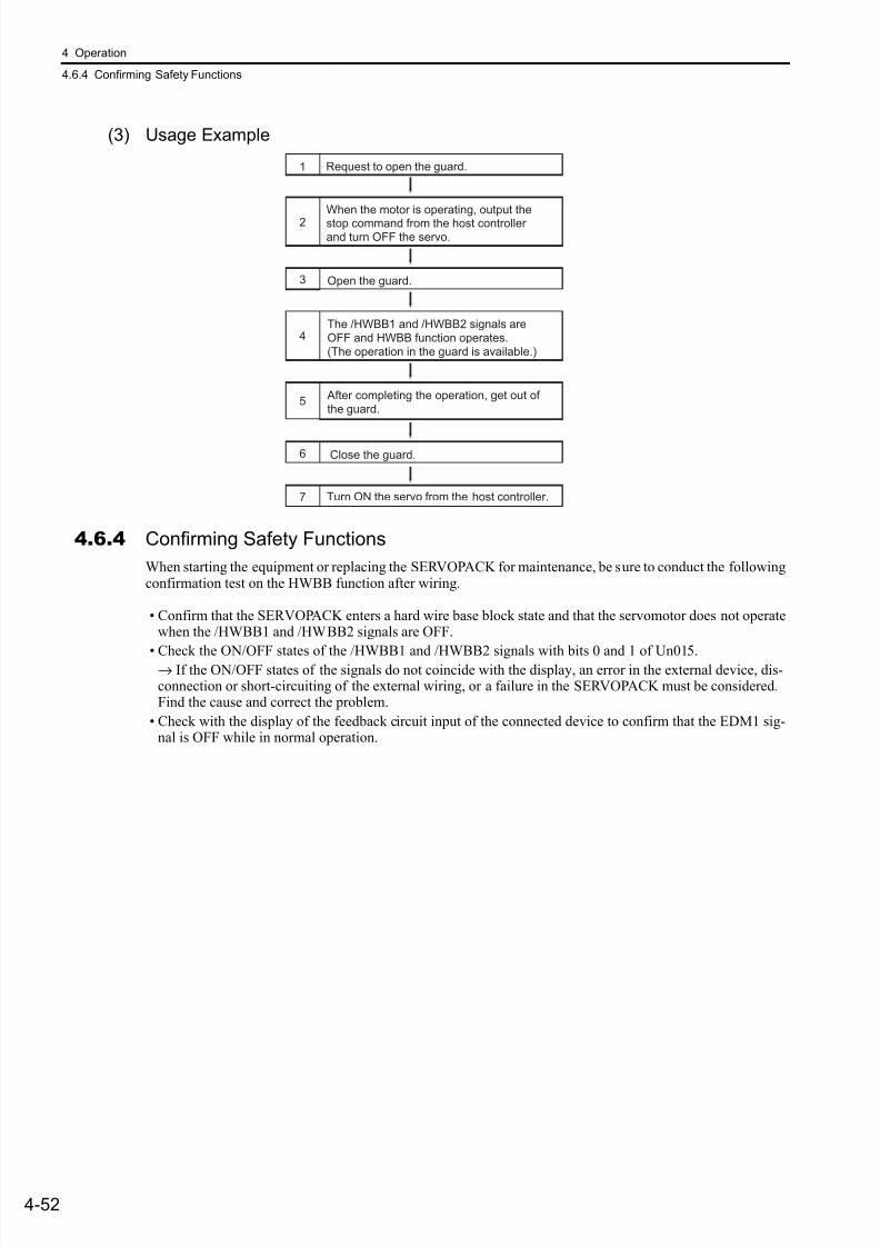
7/17/2019 Manual Yaskawa_servo_drive.pdf
http://slidepdf.com/reader/full/manual-yaskawaservodrivepdf 135/328
4 Operation
4.6.4 Confirming Safety Functions
4-52
(3) Usage Example
4.6.4 Confirming Safety Functions
When starting the equipment or replacing the SERVOPACK for maintenance, be sure to conduct the followingconfirmation test on the HWBB function after wiring.
• Confirm that the SERVOPACK enters a hard wire base block state and that the servomotor does not operatewhen the /HWBB1 and /HWBB2 signals are OFF.
• Check the ON/OFF states of the /HWBB1 and /HWBB2 signals with bits 0 and 1 of Un015.→ If the ON/OFF states of the signals do not coincide with the display, an error in the external device, dis-connection or short-circuiting of the external wiring, or a failure in the SERVOPACK must be considered.Find the cause and correct the problem.
• Check with the display of the feedback circuit input of the connected device to confirm that the EDM1 sig-nal is OFF while in normal operation.
1
2
3
4
Request to open the guard.
When the motor is operating, output thestop command from the host controllerand turn OFF the servo.
Open the guard.
The /HWBB1 and /HWBB2 signals areOFF and HWBB function operates.(The operation in the guard is available.)
5
6
7 Turn ON the servo from the host controller.
After completing the operation, get out of the guard.
Close the guard.
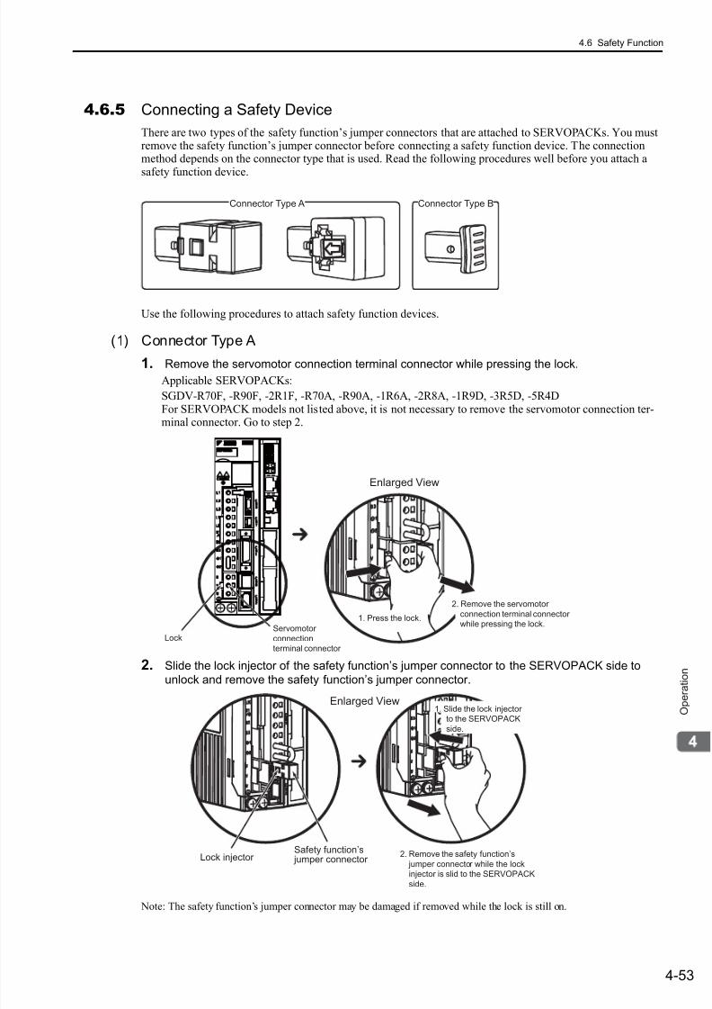
7/17/2019 Manual Yaskawa_servo_drive.pdf
http://slidepdf.com/reader/full/manual-yaskawaservodrivepdf 136/328
4.6 Safety Function
4-53
O p e r a t i o n
4.6.5 Connecting a Safety Device
There are two types of the safety function’s jumper connectors that are attached to SERVOPACKs. You mustremove the safety function’s jumper connector before connecting a safety function device. The connectionmethod depends on the connector type that is used. Read the following procedures well before you attach a
safety function device.
Use the following procedures to attach safety function devices.
(1) Connector Type A
1. Remove the servomotor connection terminal connector while pressing the lock.
Applicable SERVOPACKs:
SGDV-R70F, -R90F, -2R1F, -R70A, -R90A, -1R6A, -2R8A, -1R9D, -3R5D, -5R4DFor SERVOPACK models not listed above, it is not necessary to remove the servomotor connection ter-minal connector. Go to step 2.
2. Slide the lock injector of the safety function’s jumper connector to the SERVOPACK side to
unlock and remove the safety function’s jumper connector.
Note: The safety function’s jumper connector may be damaged if removed while the lock is still on.
Connector Type A Connector Type B
Enlarged View
Servomotor
connection
terminal connector
Lock
2. Remove the servomotor
connection terminal connector
while pressing the lock.1. Press the lock.
Lock injector Safety function’s
jumper connector
Enlarged View
Remove the safety function’s
jumper connector while the lock
injector is slid to the SERVOPACK
side.
2.
1. Slide the lock injectorto the SERVOPACK
side.
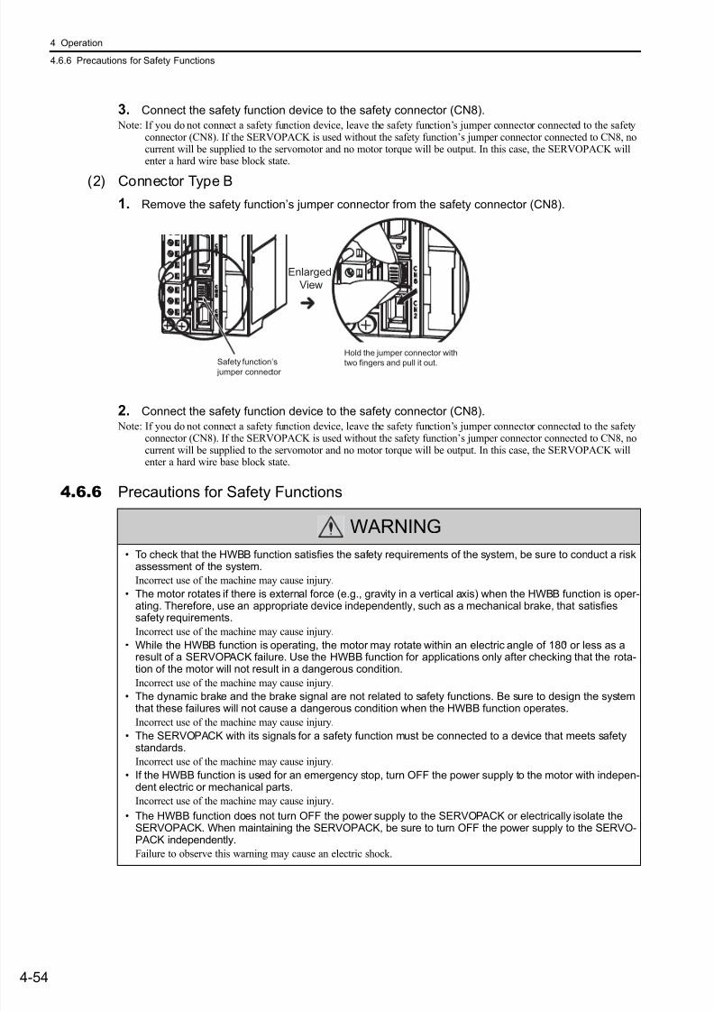
7/17/2019 Manual Yaskawa_servo_drive.pdf
http://slidepdf.com/reader/full/manual-yaskawaservodrivepdf 137/328
4 Operation
4.6.6 Precautions for Safety Functions
4-54
3. Connect the safety function device to the safety connector (CN8).
Note: If you do not connect a safety function device, leave the safety function’s jumper connector connected to the safetyconnector (CN8). If the SERVOPACK is used without the safety function’s jumper connector connected to CN8, nocurrent will be supplied to the servomotor and no motor torque will be output. In this case, the SERVOPACK willenter a hard wire base block state.
(2) Connector Type B
1. Remove the safety function’s jumper connector from the safety connector (CN8).
2. Connect the safety function device to the safety connector (CN8).
Note: If you do not connect a safety function device, leave the safety function’s jumper connector connected to the safetyconnector (CN8). If the SERVOPACK is used without the safety function’s jumper connector connected to CN8, nocurrent will be supplied to the servomotor and no motor torque will be output. In this case, the SERVOPACK willenter a hard wire base block state.
4.6.6 Precautions for Safety Functions
Enlarged
View
Safety function’s
jumper connector
Hold the jumper connector withtwo fingers and pull it out.
WARNING• To check that the HWBB function satisfies the safety requirements of the system, be sure to conduct a risk
assessment of the system.
Incorrect use of the machine may cause injury.
• The motor rotates if there is external force (e.g., gravity in a vertical axis) when the HWBB function is oper-ating. Therefore, use an appropriate device independently, such as a mechanical brake, that satisfiessafety requirements.
Incorrect use of the machine may cause injury.
• While the HWBB function is operating, the motor may rotate within an electric angle of 180° or less as aresult of a SERVOPACK failure. Use the HWBB function for applications only after checking that the rota-tion of the motor will not result in a dangerous condition.
Incorrect use of the machine may cause injury.
• The dynamic brake and the brake signal are not related to safety functions. Be sure to design the system
that these failures will not cause a dangerous condition when the HWBB function operates.Incorrect use of the machine may cause injury.
• The SERVOPACK with its signals for a safety function must be connected to a device that meets safetystandards.
Incorrect use of the machine may cause injury.
• If the HWBB function is used for an emergency stop, turn OFF the power supply to the motor with indepen-dent electric or mechanical parts.
Incorrect use of the machine may cause injury.
• The HWBB function does not turn OFF the power supply to the SERVOPACK or electrically isolate theSERVOPACK. When maintaining the SERVOPACK, be sure to turn OFF the power supply to the SERVO-PACK independently.
Failure to observe this warning may cause an electric shock.
7/17/2019 Manual Yaskawa_servo_drive.pdf
http://slidepdf.com/reader/full/manual-yaskawaservodrivepdf 138/3285-1
A d j u s t m e
n t s
5
Adjustments
5.1 Adjustments and Basic Adjustment Procedure . . . . . . . . . . . . . . . . . . . . .5-3
5.1.1 Adjustments . . . . . . . . . . . . . . . . . . . . . . . . . . . . . . . . . . . . . . . . . . . . . . . . . . . . . . . . 5-3
5.1.2 Basic Adjustment Procedure . . . . . . . . . . . . . . . . . . . . . . . . . . . . . . . . . . . . . . . . . . . . 5-4
5.1.3 Monitoring Analog Signals . . . . . . . . . . . . . . . . . . . . . . . . . . . . . . . . . . . . . . . . . . . . . 5-5
5.1.4 Safety Precautions on Adjustment of Servo Gains . . . . . . . . . . . . . . . . . . . . . . . . . . . 5-8
5.2 Tuning-less Function . . . . . . . . . . . . . . . . . . . . . . . . . . . . . . . . . . . . . . . . 5-10
5.2.1 Tuning-less Function . . . . . . . . . . . . . . . . . . . . . . . . . . . . . . . . . . . . . . . . . . . . . . . . . 5-10
5.2.2 Tuning-less Levels Setting (Fn200) Procedure . . . . . . . . . . . . . . . . . . . . . . . . . . . . . 5-13
5.3 Advanced Autotuning (Fn201) . . . . . . . . . . . . . . . . . . . . . . . . . . . . . . . .5-155.3.1 Advanced Autotuning . . . . . . . . . . . . . . . . . . . . . . . . . . . . . . . . . . . . . . . . . . . . . . . . 5-15
5.3.2 Advanced Autotuning Procedure . . . . . . . . . . . . . . . . . . . . . . . . . . . . . . . . . . . . . . . 5-17
5.3.3 Related Parameters . . . . . . . . . . . . . . . . . . . . . . . . . . . . . . . . . . . . . . . . . . . . . . . . . 5-23
5.4 Advanced Autotuning by Reference (Fn202) . . . . . . . . . . . . . . . . . . . . .5-24
5.4.1 Advanced Autotuning by Reference . . . . . . . . . . . . . . . . . . . . . . . . . . . . . . . . . . . . . 5-24
5.4.2 Advanced Autotuning by Reference Procedure . . . . . . . . . . . . . . . . . . . . . . . . . . . . 5-26
5.4.3 Related Parameters . . . . . . . . . . . . . . . . . . . . . . . . . . . . . . . . . . . . . . . . . . . . . . . . . 5-30
5.5 One-parameter Tuning (Fn203) . . . . . . . . . . . . . . . . . . . . . . . . . . . . . . .5-31
5.5.1 One-parameter Tuning . . . . . . . . . . . . . . . . . . . . . . . . . . . . . . . . . . . . . . . . . . . . . . . 5-31
5.5.2 One-parameter Tuning Procedure . . . . . . . . . . . . . . . . . . . . . . . . . . . . . . . . . . . . . . 5-32
5.5.3 One-parameter Tuning Example . . . . . . . . . . . . . . . . . . . . . . . . . . . . . . . . . . . . . . . . 5-385.5.4 Related Parameters . . . . . . . . . . . . . . . . . . . . . . . . . . . . . . . . . . . . . . . . . . . . . . . . . 5-39
5.6 Anti-resonance Control Adjustment Function (Fn204) . . . . . . . . . . . . . .5-40
5.6.1 Anti-resonance Control Adjustment Function . . . . . . . . . . . . . . . . . . . . . . . . . . . . . . 5-40
5.6.2 Anti-resonance Control Adjustment Function Operating Procedure . . . . . . . . . . . . . 5-41
5.6.3 Related Parameters . . . . . . . . . . . . . . . . . . . . . . . . . . . . . . . . . . . . . . . . . . . . . . . . . 5-45
5.7 Vibration Suppression Function (Fn205) . . . . . . . . . . . . . . . . . . . . . . . .5-46
5.7.1 Vibration Suppression Function . . . . . . . . . . . . . . . . . . . . . . . . . . . . . . . . . . . . . . . . 5-46
5.7.2 Vibration Suppression Function Operating Procedure . . . . . . . . . . . . . . . . . . . . . . . 5-47
5.7.3 Related Parameters . . . . . . . . . . . . . . . . . . . . . . . . . . . . . . . . . . . . . . . . . . . . . . . . . 5-50

7/17/2019 Manual Yaskawa_servo_drive.pdf
http://slidepdf.com/reader/full/manual-yaskawaservodrivepdf 139/328
5 Adjustments
5-2
5.8 Additional Adjustment Function . . . . . . . . . . . . . . . . . . . . . . . . . . . . . . . 5-51
5.8.1 Switching Gain Settings . . . . . . . . . . . . . . . . . . . . . . . . . . . . . . . . . . . . . . . . . . . . . . .5-51
5.8.2 Friction Compensation . . . . . . . . . . . . . . . . . . . . . . . . . . . . . . . . . . . . . . . . . . . . . . . .5-56
5.8.3 Current Control Mode Selection . . . . . . . . . . . . . . . . . . . . . . . . . . . . . . . . . . . . . . . .5-58
5.8.4 Current Gain Level Setting . . . . . . . . . . . . . . . . . . . . . . . . . . . . . . . . . . . . . . . . . . . .5-58
5.8.5 Speed Detection Method Selection . . . . . . . . . . . . . . . . . . . . . . . . . . . . . . . . . . . . . .5-58
5.9 Compatible Adjustment Function . . . . . . . . . . . . . . . . . . . . . . . . . . . . . . 5-59
5.9.1 Feedforward Reference . . . . . . . . . . . . . . . . . . . . . . . . . . . . . . . . . . . . . . . . . . . . . . .5-59
5.9.2 Using the Mode Switch (P/PI Switching) . . . . . . . . . . . . . . . . . . . . . . . . . . . . . . . . . .5-59
5.9.3 Torque Reference Filter . . . . . . . . . . . . . . . . . . . . . . . . . . . . . . . . . . . . . . . . . . . . . . .5-64
5.9.4 Position Integral Time Constant . . . . . . . . . . . . . . . . . . . . . . . . . . . . . . . . . . . . . . . . .5-65
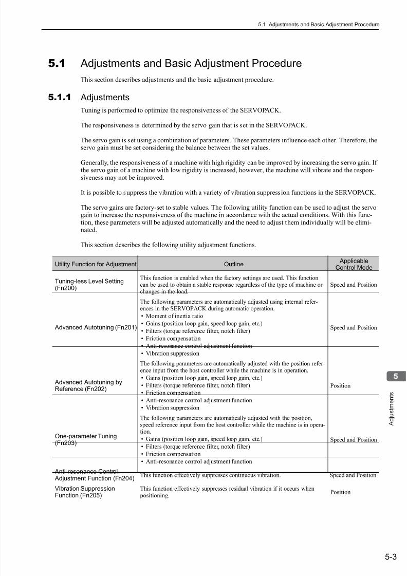
7/17/2019 Manual Yaskawa_servo_drive.pdf
http://slidepdf.com/reader/full/manual-yaskawaservodrivepdf 140/328
5.1 Adjustments and Basic Adjustment Procedure
5-3
A d j u s t m e
n t s
5.1 Adjustments and Basic Adjustment Procedure
This section describes adjustments and the basic adjustment procedure.
5.1.1 AdjustmentsTuning is performed to optimize the responsiveness of the SERVOPACK.
The responsiveness is determined by the servo gain that is set in the SERVOPACK.
The servo gain is set using a combination of parameters. These parameters influence each other. Therefore, theservo gain must be set considering the balance between the set values.
Generally, the responsiveness of a machine with high rigidity can be improved by increasing the servo gain. Ifthe servo gain of a machine with low rigidity is increased, however, the machine will vibrate and the respon-siveness may not be improved.
It is possible to suppress the vibration with a variety of vibration suppression functions in the SERVOPACK.
The servo gains are factory-set to stable values. The following utility function can be used to adjust the servogain to increase the responsiveness of the machine in accordance with the actual conditions. With this func-tion, these parameters will be adjusted automatically and the need to adjust them individually will be elimi-nated.
This section describes the following utility adjustment functions.
Utility Function for Adjustment Outline Applicable
Control Mode
Tuning-less Level Setting(Fn200)
This function is enabled when the factory settings are used. This functioncan be used to obtain a stable response regardless of the type of machine orchanges in the load.
Speed and Position
Advanced Autotuning (Fn201)
The following parameters are automatically adjusted using internal refer-ences in the SERVOPACK during automatic operation.
• Moment of inertia ratio
• Gains (position loop gain, speed loop gain, etc.)
• Filters (torque reference filter, notch filter)
• Friction compensation
• Anti-resonance control adjustment function
• Vibration suppression
Speed and Position
Advanced Autotuning byReference (Fn202)
The following parameters are automatically adjusted with the position refer-ence input from the host controller while the machine is in operation.
• Gains (position loop gain, speed loop gain, etc.)
• Filters (torque reference filter, notch filter)
• Friction compensation
• Anti-resonance control adjustment function
• Vibration suppression
Position
One-parameter Tuning(Fn203)
The following parameters are automatically adjusted with the position,speed reference input from the host controller while the machine is in opera-tion.
• Gains (position loop gain, speed loop gain, etc.)
• Filters (torque reference filter, notch filter)
• Friction compensation
• Anti-resonance control adjustment function
Speed and Position
Anti-resonance Control Adjustment Function (Fn204)
This function effectively suppresses continuous vibration. Speed and Position
Vibration SuppressionFunction (Fn205)
This function effectively suppresses residual vibration if it occurs when positioning.
Position
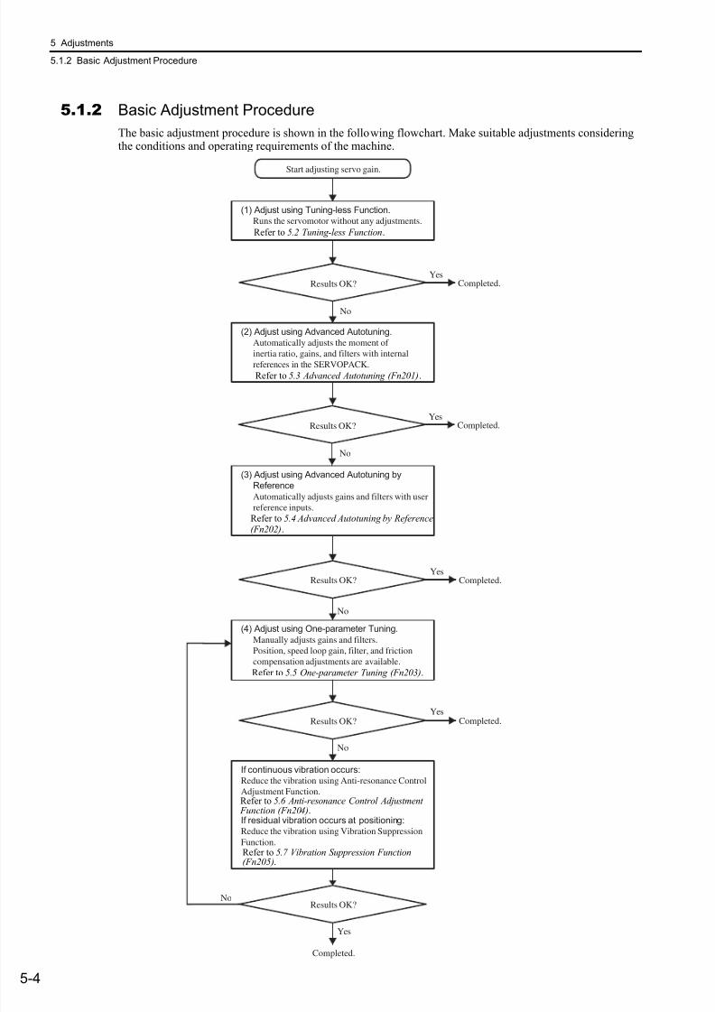
7/17/2019 Manual Yaskawa_servo_drive.pdf
http://slidepdf.com/reader/full/manual-yaskawaservodrivepdf 141/328
5 Adjustments
5.1.2 Basic Adjustment Procedure
5-4
5.1.2 Basic Adjustment Procedure
The basic adjustment procedure is shown in the following flowchart. Make suitable adjustments consideringthe conditions and operating requirements of the machine.
Start adjusting servo gain.
(2) Adjust using Advanced Autotuning.Automatically adjusts the moment of
inertia ratio, gains, and filters with internalreferences in the SERVOPACK.
Completed.
Completed.
(1) Adjust using Tuning-less Function.Runs the servomotor without any adjustments.
(3) Adjust using Advanced Autotuning by
Reference
Automatically adjusts gains and filters with user
reference inputs.
(4) Adjust using One-parameter Tuning.
Manually adjusts gains and filters.
Position, speed loop gain, filter, and friction
compensation adjustments are available.
If continuous vibration occurs:Reduce the vibration using Anti-resonance Control
Adjustment Function.
If residual vibration occurs at positioning:Reduce the vibration using Vibration Suppression
Function.
Results OK?
Results OK?
Results OK?
Results OK?
Completed.
Yes
Yes
Completed.Yes
No
Yes
No
No
No
Results OK? Completed.Yes
No
Refer to 5.2 Tuning-less Function.
Refer to 5.3 Advanced Autotuning (Fn201).
Refer to 5.4 Advanced Autotuning by Reference
(Fn202).
Refer to 5.5 One-parameter Tuning (Fn203).
Refer to 5.6 Anti-resonance Control Adjustment Function (Fn204).
Refer to 5.7 Vibration Suppression Function(Fn205).
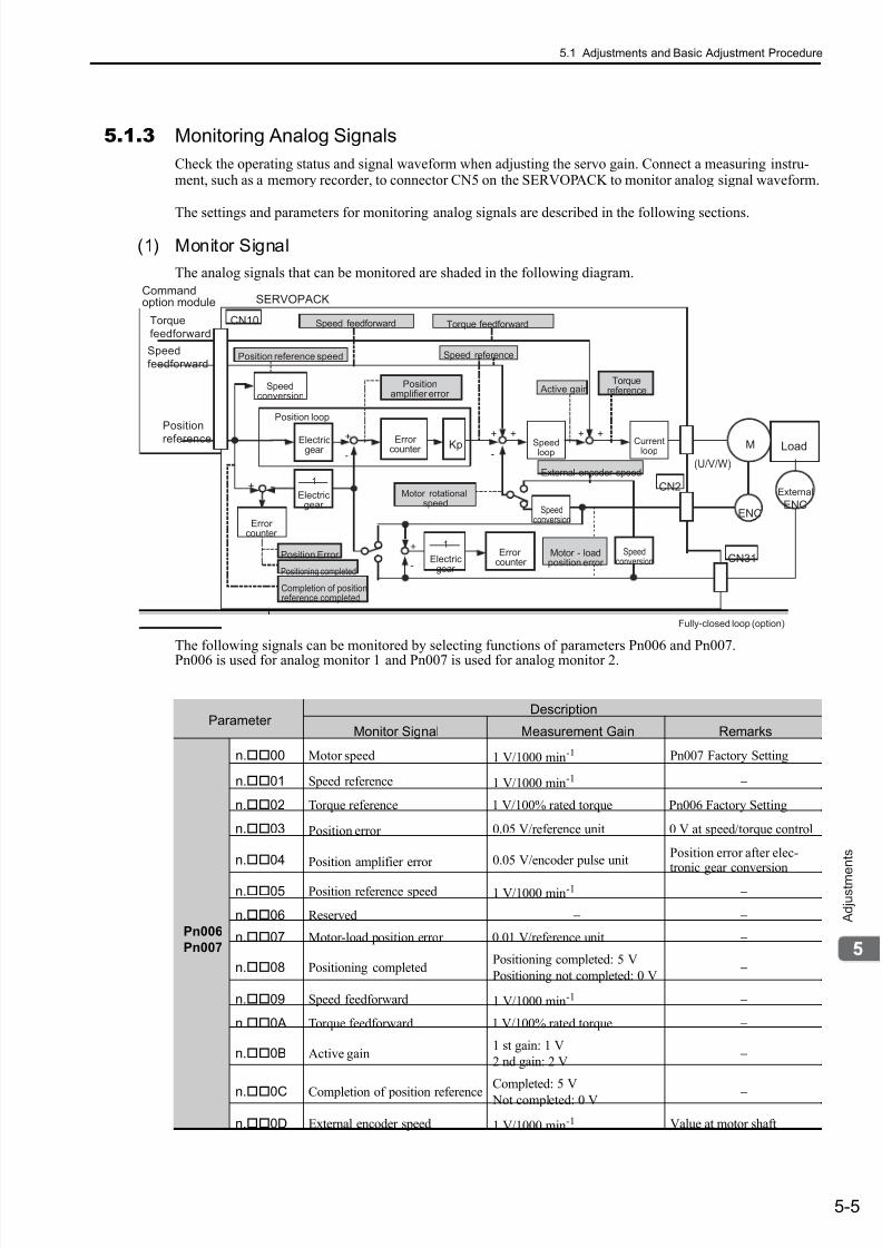
7/17/2019 Manual Yaskawa_servo_drive.pdf
http://slidepdf.com/reader/full/manual-yaskawaservodrivepdf 142/328
5.1 Adjustments and Basic Adjustment Procedure
5-5
A d j u s t m e
n t s
5.1.3 Monitoring Analog Signals
Check the operating status and signal waveform when adjusting the servo gain. Connect a measuring instru-ment, such as a memory recorder, to connector CN5 on the SERVOPACK to monitor analog signal waveform.
The settings and parameters for monitoring analog signals are described in the following sections.
(1) Monitor Signal
The analog signals that can be monitored are shaded in the following diagram.
The following signals can be monitored by selecting functions of parameters Pn006 and Pn007.Pn006 is used for analog monitor 1 and Pn007 is used for analog monitor 2.
Kp
1
(U/V/W)-
++
-
+ + +
+
-
-+1
Commandoption module
1
MKp
CN31
ENC
CN2
CN10Torque
feedforward
Speed
feedforward
Position
reference
SERVOPACK
Speed feedforward
Position reference speed
Positionamplifier error
Motor rotationalspeed
Speed reference
Active gainTorque
referenceSpeedconversion
Electricgear
Speedloop
Currentloop
Fully-closed loop (option)
Electricgear
Electricgear
Position loop
Torque feedforward
Errorcounter
Errorcounter
Errorcounter
Load
Position Error
Positioning completed
Completion of positionreference completed
External encoder speed
Speedconversion
Speedconversion
Motor - loadposition error
External
ENC
Parameter Description
Monitor Signal Measurement Gain Remarks
Pn006
Pn007
n.00 Motor speed 1 V/1000 min-1 Pn007 Factory Setting
n.01 Speed reference 1 V/1000 min-1−
n.02 Torque reference 1 V/100% rated torque Pn006 Factory Setting
n.03 Position error 0.05 V/reference unit 0 V at speed/torque control
n.04 Position amplifier error 0.05 V/encoder pulse unitPosition error after elec-tronic gear conversion
n.05 Position reference speed 1 V/1000 min-1−
n.06 Reserved − −
n.07 Motor-load position error 0.01 V/reference unit −
n.08 Positioning completedPositioning completed: 5 V
Positioning not completed: 0 V −
n.09 Speed feedforward 1 V/1000 min-1−
n.0A Torque feedforward 1 V/100% rated torque −
n.0B Active gain1 st gain: 1 V
2 nd gain: 2 V −
n.0C Completion of position referenceCompleted: 5 V
Not completed: 0 V −
n.0D External encoder speed 1 V/1000 min-1 Value at motor shaft
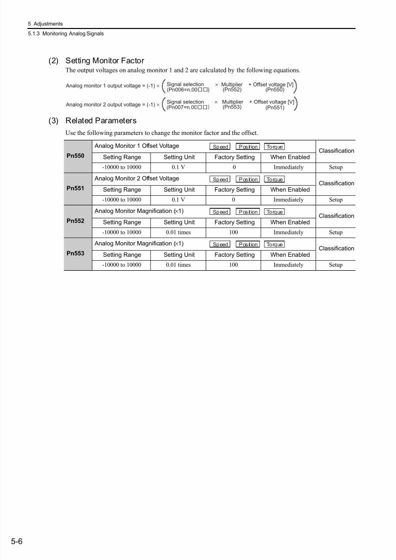
7/17/2019 Manual Yaskawa_servo_drive.pdf
http://slidepdf.com/reader/full/manual-yaskawaservodrivepdf 143/328
5 Adjustments
5.1.3 Monitoring Analog Signals
5-6
(2) Setting Monitor Factor The output voltages on analog monitor 1 and 2 are calculated by the following equations.
(3) Related Parameters
Use the following parameters to change the monitor factor and the offset.
Analog monitor 1 output voltage = (-1) ×
Analog monitor 2 output voltage = (-1) ×
(Pn006=n.00 ) (Pn552)
(Pn007=n.00
× Multiplier + Offset voltage [V]
× Multiplier + Offset voltage [V]
(Pn550)
(Pn551) (Pn553)
Signal selection
Signal selection
Pn550
Analog Monitor 1 Offset VoltageClassification
Setting Range Setting Unit Factory Setting When Enabled
-10000 to 10000 0.1 V 0 Immediately Setup
Pn551
Analog Monitor 2 Offset VoltageClassification
Setting Range Setting Unit Factory Setting When Enabled
-10000 to 10000 0.1 V 0 Immediately Setup
Pn552
Analog Monitor Magnification (×1)Classification
Setting Range Setting Unit Factory Setting When Enabled
-10000 to 10000 0.01 times 100 Immediately Setup
Pn553
Analog Monitor Magnification (×1)Classification
Setting Range Setting Unit Factory Setting When Enabled
-10000 to 10000 0.01 times 100 Immediately Setup
Speed Position Torque
Speed Position Torque
Speed Position Torque
Speed Position Torque
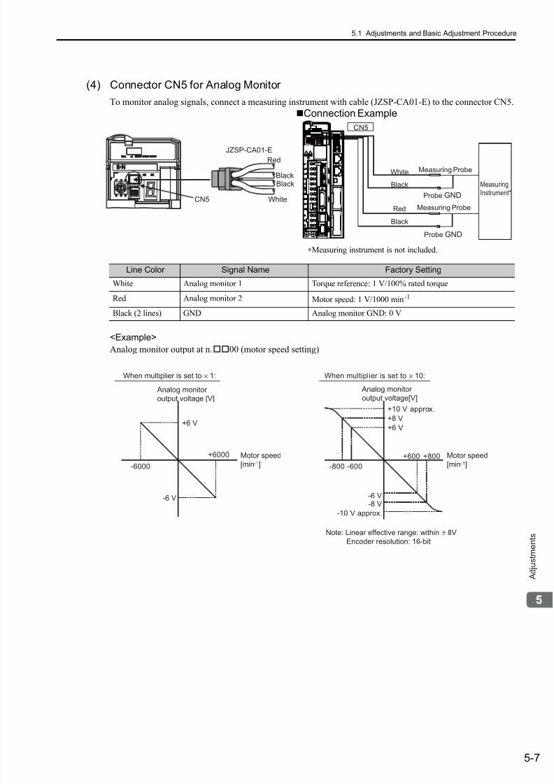
7/17/2019 Manual Yaskawa_servo_drive.pdf
http://slidepdf.com/reader/full/manual-yaskawaservodrivepdf 144/328
5.1 Adjustments and Basic Adjustment Procedure
5-7
A d j u s t m e
n t s
(4) Connector CN5 for Analog Monitor
To monitor analog signals, connect a measuring instrument with cable (JZSP-CA01-E) to the connector CN5.
<Example>
Analog monitor output at n.00 (motor speed setting)
Line Color Signal Name Factory Setting
White Analog monitor 1 Torque reference: 1 V/100% rated torque
Red Analog monitor 2 Motor speed: 1 V/1000 min-1
Black (2 lines) GND Analog monitor GND: 0 V
CN5
JZSP-CA01-E
Black
White
Red
Black
CN5
ProbeGND
ProbeGND
Measuring Probe
Measuring Probe
Measuring
Instrument*
White
Red
Black
Black
Connection Example
∗Measuring instrument is not included.
+6 V
-6 V
-600
+600
+8 V
-8 V
-800
+800
+10 V approx.
-10 V approx.
+6 V
-6 V
-6000
+6000
Analog monitor
output voltage [V]
Analog monitor
output voltage[V]
When multiplier is set to ×
1: When multiplier is set to ×
10:
Motor speed
[min-1]
Motor speed
[min-1]
Note: Linear effective range: within ±
8V
Encoder resolution: 16-bit
7/17/2019 Manual Yaskawa_servo_drive.pdf
http://slidepdf.com/reader/full/manual-yaskawaservodrivepdf 145/328
5 Adjustments
5.1.4 Safety Precautions on Adjustment of Servo Gains
5-8
5.1.4 Safety Precautions on Adjustment of Servo Gains
Yaskawa recommends that the following protective functions of the SERVOPACK are set to the correct set-tings before starting to adjust the servo gains.
(1) Overtravel Function
Set the overtravel function. For details on how to set the overtravel function, refer to 4.2.3 Overtravel .
(2) Torque LimitCalculate the torque required to operate the machine. Set the torque limits so that the output torque will not begreater than required. Setting the torque limits can reduce the amount of shock applied to the machine in colli-sions and other cases.If the torque is set below the level of torque required to operate the machine, overshooting or vibration mayoccur.
(3) Excessive Position Error Alarm Level
The excessive position error alarm is a protective function that will be enabled when the servo drive is used in position control mode.
For the optimum setting, the servomotor will be stopped after the error occurs if the servomotor performsunpredictably after receiving a reference.The position error is the difference between the position reference and the actual position. The position errorcan be calculated from the position loop gain (Pn102) and the motor speed with the following equation.
• Excessive Position Error Alarm Level (Pn520 [reference unit])
∗1. Refer to 4.2.4 Electronic Gear .∗2. To check the setting for Pn102, set the parameter display to “Displays all parameters” (Pn00B.0 = 1).
Set the level to a value that satisfies these equations, and no alarm will be generated during normal operation.The servomotor will be stopped, however, if the servomotor runs unpredictably after a reference is input. Atthe end of the equation, a coefficient is shown as “× (1.2 to 2).” This coefficient is used to add a margin that
prevents a faulty alarm from occurring in actual operation of the servomotor.
If the servomotor’s maximum number of rotations is 6000 min-1 and Pn102 equals 40 with an encoder resolu-tion of 20-bit (1048576), the setting of Pn520 is calculated as shown with the following equation.
If the acceleration/deceleration of the position reference exceeds the capacity of the servomotor, the servomo-tor cannot perform at the requested speed, and the allowable level for position error will be increased as not tosatisfy these equations. If so, lower the level of the acceleration/deceleration for the position reference so thatthe servomotor can perform at the requested speed or raise the allowable level of the position errors.
CAUTION
• If adjusting the servo gains, observe the following precautions.
• Do not touch the rotating section of the motor while the servomotor power is ON.
• Before starting the servomotor, make sure that the emergency-stop circuit works correctly.
• Make sure that a trial run has been performed without any trouble.
• Install a safety brake on the machine.
Position Error = ×Motor Speed [min ]-1
60
Encoder Resolution*1
Pn102 (1/s)*2
Pn520 > × × (1.2 to 2)Max. Motor Speed [min ]
-1
60
Encoder Resolution*1
Pn102 (1/s)*2
Pn520 =
2621440 × 2
5242880 (The factor setting of Pn520)
× × 26000
60
1048576
40
=
=
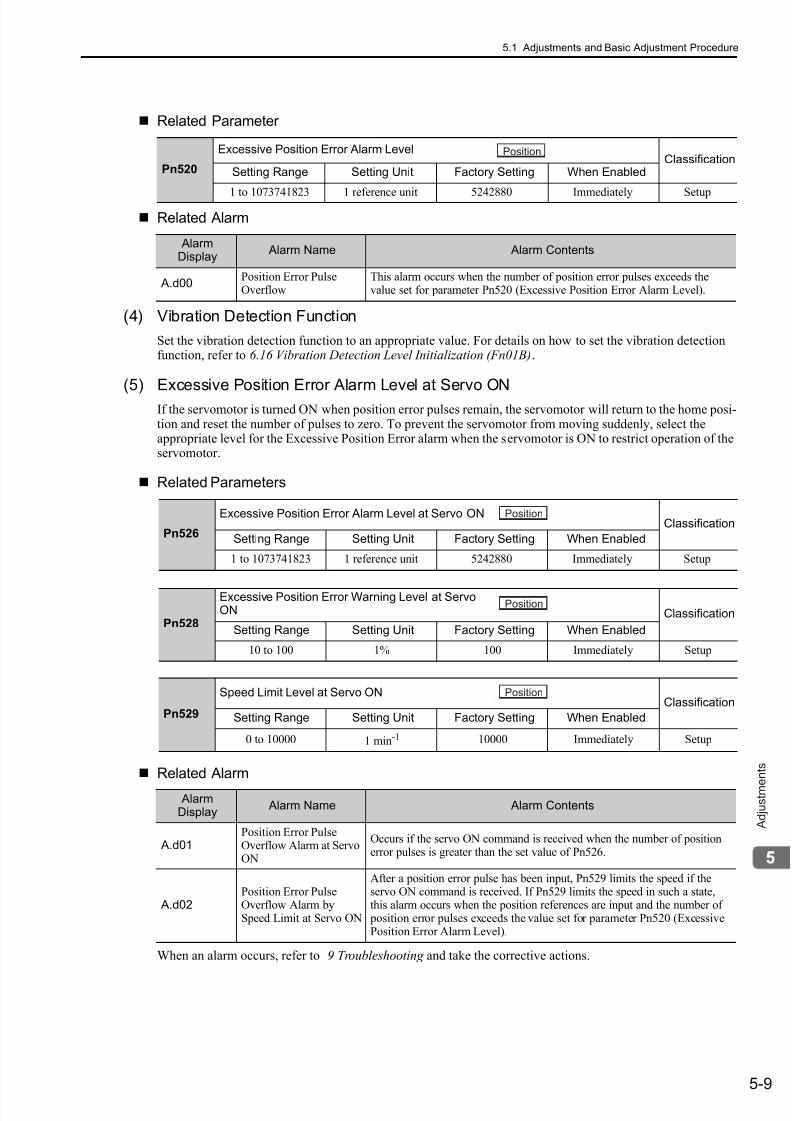
7/17/2019 Manual Yaskawa_servo_drive.pdf
http://slidepdf.com/reader/full/manual-yaskawaservodrivepdf 146/328
5.1 Adjustments and Basic Adjustment Procedure
5-9
A d j u s t m e
n t s
Related Parameter
Related Alarm
(4) Vibration Detection Function
Set the vibration detection function to an appropriate value. For details on how to set the vibration detectionfunction, refer to 6.16 Vibration Detection Level Initialization (Fn01B).
(5) Excessive Position Error Alarm Level at Servo ONIf the servomotor is turned ON when position error pulses remain, the servomotor will return to the home posi-tion and reset the number of pulses to zero. To prevent the servomotor from moving suddenly, select theappropriate level for the Excessive Position Error alarm when the servomotor is ON to restrict operation of theservomotor.
Related Parameters
Related Alarm
When an alarm occurs, refer to 9 Troubleshooting and take the corrective actions.
Pn520
Excessive Position Error Alarm LevelClassification
Setting Range Setting Unit Factory Setting When Enabled
1 to 1073741823 1 reference unit 5242880 Immediately Setup
AlarmDisplay
Alarm Name Alarm Contents
A.d00Position Error PulseOverflow
This alarm occurs when the number of position error pulses exceeds thevalue set for parameter Pn520 (Excessive Position Error Alarm Level).
Position
Pn526
Excessive Position Error Alarm Level at Servo ONClassification
Setting Range Setting Unit Factory Setting When Enabled
1 to 1073741823 1 reference unit 5242880 Immediately Setup
Position
Pn528
Excessive Position Error Warning Level at ServoON Classification
Setting Range Setting Unit Factory Setting When Enabled
10 to 100 1% 100 Immediately Setup
Pn529
Speed Limit Level at Servo ONClassification
Setting Range Setting Unit Factory Setting When Enabled
0 to 10000 1 min-1 10000 Immediately Setup
Position
Position
AlarmDisplay
Alarm Name Alarm Contents
A.d01Position Error PulseOverflow Alarm at ServoON
Occurs if the servo ON command is received when the number of positionerror pulses is greater than the set value of Pn526.
A.d02Position Error PulseOverflow Alarm bySpeed Limit at Servo ON
After a position error pulse has been input, Pn529 limits the speed if theservo ON command is received. If Pn529 limits the speed in such a state,this alarm occurs when the position references are input and the number of position error pulses exceeds the value set for parameter Pn520 (ExcessivePosition Error Alarm Level).

7/17/2019 Manual Yaskawa_servo_drive.pdf
http://slidepdf.com/reader/full/manual-yaskawaservodrivepdf 147/328
5 Adjustments
5.2.1 Tuning-less Function
5-10
5.2 Tuning-less Function
The tuning-less function is enabled in the factory settings. Do not disable this function for normal applica-tions. If resonance is generated or excessive vibration occurs during position control, refer to 5.2.2 Tuning-less
Levels Setting (Fn200) Procedure and reduce the set value of Pn170.2 for the tuning-less adjustment level and
the set value in Pn170.3 for the tuning-less load level.
5.2.1 Tuning-less Function
The tuning-less function obtains a stable response without adjustment regardless of the type of machine orchanges in the load.
(1) Enabling/Disabling Tuning-less Function
The following parameter is used to enable or disable the tuning-less function.
(2) Application Restrictions
The tuning-less function can be used in position control or speed control. This function is not available in
torque control. The following application restrictions apply to the tuning-less function.
CAUTION
• The tuning-less function is enabled in the factory settings. A sound may be heard for a moment when theservomotor power is turned ON for the first time after the SERVOPACK is mounted to the machine. Thissound does not indicate any problems; it means that the automatic notch filter was set. The sound will notbe heard from the next time the servomotor power is turned ON. For details on the automatic notch filter,refer to (3) Automatically Setting the Notch Filter on the next page.
• Set the mode to 2 in Fn200 if a 13-bit encoder is used with the load moment of inertia ratio set to x10 orhigher.
• The servomotor may vibrate if the load moment of inertia ratio exceeds the allowable moment of inertia ofthe servomotor.
If vibration occurs, set the mode to 2 in Fn200 or lower the adjustment level.
Parameter Meaning When Enabled Classification
Pn170
n.0 Disables tuning-less function.
After restart Setup
n.1 Enables tuning-less function. [Factory setting]
n.0 Used as speed control. [Factory setting]
n.1Used as speed control and host controller used as position control.
Control Function Availability Remarks
Vibration detection level initialization
(Fn01B) Available
Advanced autotuning (Fn201)Available
(Some conditions apply)
• This function can be used when themoment of inertia is calculated.
• While this function is being used, the tun-ing-less function cannot be used tempo-rarily.
Advanced autotuning by reference (Fn202) Not available
One-parameter tuning (Fn203) Not available
Anti-resonance control adjustmentfunction (Fn204)
Not available
Vibration suppression function (Fn205) Not available
EasyFFT (Fn206) AvailableWhile this function is being used, the tuning-less function cannot be used temporarily.
Friction compensation Not available
Gain switching Not available
Offline Moment of Inertia Setting * Not available

7/17/2019 Manual Yaskawa_servo_drive.pdf
http://slidepdf.com/reader/full/manual-yaskawaservodrivepdf 148/328
5.2 Tuning-less Function
5-11
A d j u s t m e
n t s
∗ Operate using SigmaWin+.
(3) Automatically Setting the Notch Filter
Usually, set this function to Auto Setting. (The notch filter is factory-set to Auto Setting.)If this function is set to Auto Setting, vibration will be detected automatically and the notch filter will be set.
Set this function to Not Auto Setting only if you do not change the notch filter setting before executing tuning-less function.
(4) Tuning-less Level Settings
Two tuning-less levels are available: the tuning-less adjustment level and tuning-less load level. Both level can be set in the Fn200 utility function and in the Pn170 parameter.
Tuning-less Adjustment Level
The servo gain can be adjusted between rigidity level 4 (high gain) and rigidity level 0 (low gain) by changingthe tuning-less adjustment level with the utility function and parameter settings.
a) By using the utility function
To change the setting, refer to 5.2.2 Tuning-less Levels Setting (Fn200) Procedure.
b) By using the parameter
Mechanical analysis * AvailableWhile this function is being used, the tuning-less function cannot be used temporarily.
(cont’d)
Control Function Availability Remarks
Parameter Meaning When Enabled Classification
Pn460
n.0 Does not set the 2nd notch filter automatically.
Immediately Tuningn.1
Sets the 2nd notch filter automatically.
[Factory setting]
Tuning Level Meaning
Level 0 Rigidity level 0
Level 1 Rigidity level 1
Level 2 Rigidity level 2
Level 3 Rigidity level 3
Level 4 Rigidity level 4 [Factory setting]
Parameter Meaning When Enabled Classification
Pn170
n.0 Rigidity level 0 (Level 0)
Immediately Setup
n.1 Rigidity level 1 (Level 1)
n.2 Rigidity level 2 (Level 2)
n.3 Rigidity level 3 (Level 3)
n.4 Rigidity level 4 (Level 4) [Factory setting]

7/17/2019 Manual Yaskawa_servo_drive.pdf
http://slidepdf.com/reader/full/manual-yaskawaservodrivepdf 149/328
5 Adjustments
5.2.1 Tuning-less Function
5-12
Tuning-less Load Level
The servo gain can be adjusted by using the utility function and parameter settings to change the load level inaccordance with the size of the load.
a) By using the utility function
To change the setting, refer to 5.2.2 Tuning-less Levels Setting (Fn200) Procedure.
b) By using by the parameter
Load Level Meaning
Mode 0 Load level: Low
Mode 1 Load level: Medium [Factory setting]
Mode 2 Load level: High
Parameter Meaning When Enabled Classification
Pn170
n.0 Load level: Low (Mode 0)
Immediately Setupn.1 Load level: Medium (Mode 1) [Factory setting]
n.2 Load level: High (Mode 2)
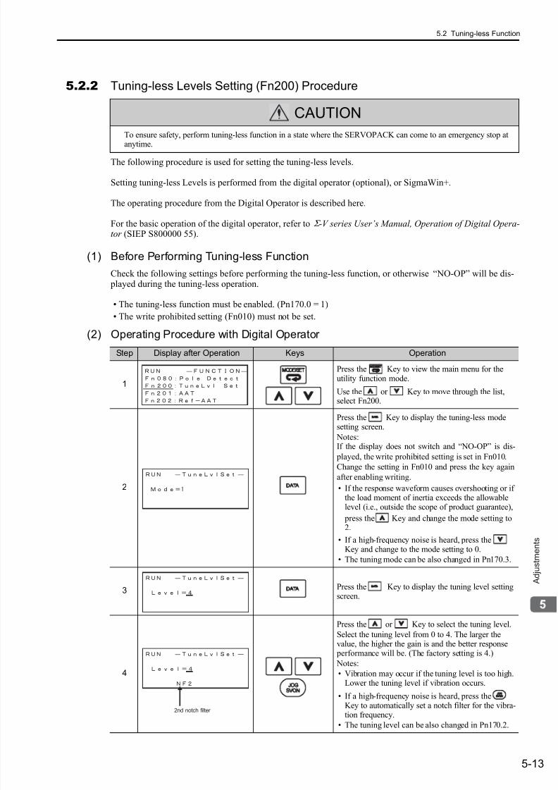
7/17/2019 Manual Yaskawa_servo_drive.pdf
http://slidepdf.com/reader/full/manual-yaskawaservodrivepdf 150/328
5.2 Tuning-less Function
5-13
A d j u s t m e
n t s
5.2.2 Tuning-less Levels Setting (Fn200) Procedure
The following procedure is used for setting the tuning-less levels.
Setting tuning-less Levels is performed from the digital operator (optional), or SigmaWin+.
The operating procedure from the Digital Operator is described here.
For the basic operation of the digital operator, refer to Σ -V series User’s Manual, Operation of Digital Opera-tor (SIEP S800000 55).
(1) Before Performing Tuning-less Function
Check the following settings before performing the tuning-less function, or otherwise “NO-OP” will be dis- played during the tuning-less operation.
• The tuning-less function must be enabled. (Pn170.0 = 1)
• The write prohibited setting (Fn010) must not be set.
(2) Operating Procedure with Digital Operator
CAUTION
To ensure safety, perform tuning-less function in a state where the SERVOPACK can come to an emergency stop atanytime.
Step Display after Operation Keys Operation
1
Press the Key to view the main menu for theutility function mode.
Use the or Key to move through the list,select Fn200.
2
Press the Key to display the tuning-less modesetting screen.
Notes:If the display does not switch and “NO-OP” is dis-
played, the write prohibited setting is set in Fn010.
Change the setting in Fn010 and press the key again
after enabling writing.
• If the response waveform causes overshooting or ifthe load moment of inertia exceeds the allowablelevel (i.e., outside the scope of product guarantee),
press the Key and change the mode setting to2.
• If a high-frequency noise is heard, press theKey and change to the mode setting to 0.
• The tuning mode can be also changed in Pn170.3.
3 Press the Key to display the tuning level settingscreen.
4
Press the or Key to select the tuning level.
Select the tuning level from 0 to 4. The larger thevalue, the higher the gain is and the better response performance will be. (The factory setting is 4.)
Notes:
• Vibration may occur if the tuning level is too high.Lower the tuning level if vibration occurs.
• If a high-frequency noise is heard, press theKey to automatically set a notch filter for the vibra-tion frequency.
• The tuning level can be also changed in Pn170.2.
2nd notch filter
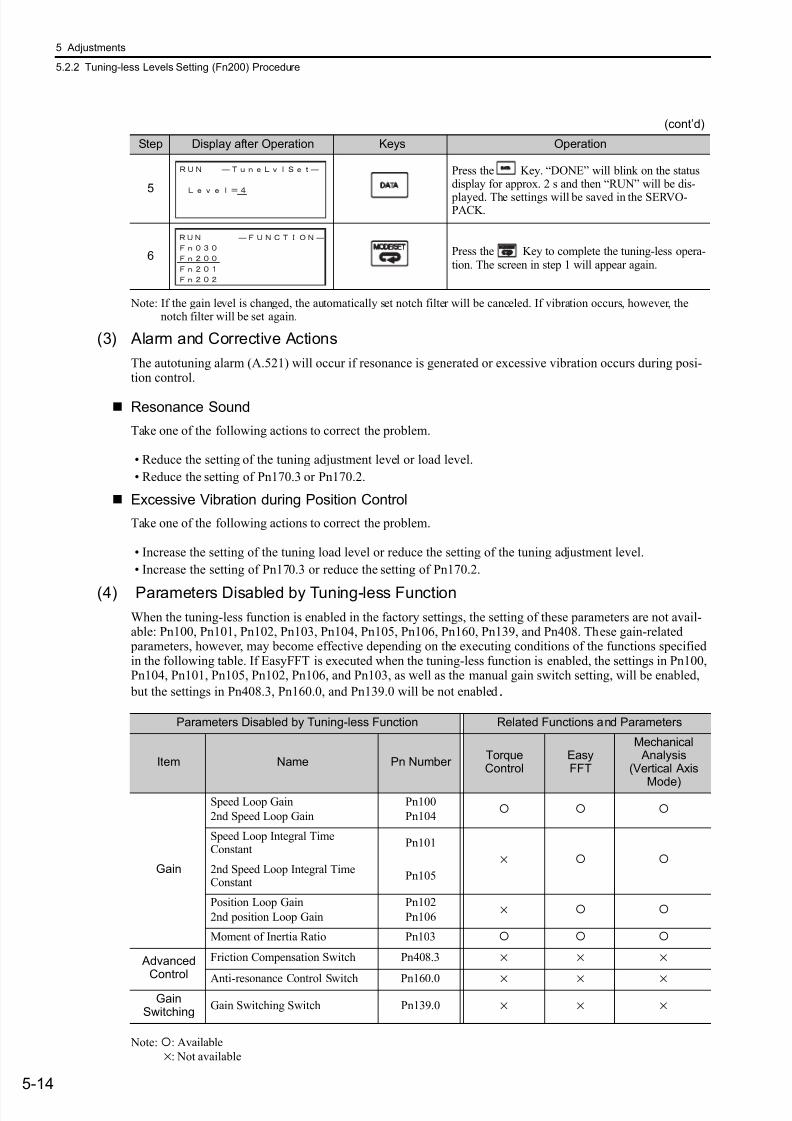
7/17/2019 Manual Yaskawa_servo_drive.pdf
http://slidepdf.com/reader/full/manual-yaskawaservodrivepdf 151/328
5 Adjustments
5.2.2 Tuning-less Levels Setting (Fn200) Procedure
5-14
Note: If the gain level is changed, the automatically set notch filter will be canceled. If vibration occurs, however, thenotch filter will be set again.
(3) Alarm and Corrective Actions
The autotuning alarm (A.521) will occur if resonance is generated or excessive vibration occurs during posi-tion control.
Resonance Sound
Take one of the following actions to correct the problem.
• Reduce the setting of the tuning adjustment level or load level.
• Reduce the setting of Pn170.3 or Pn170.2.
Excessive Vibration during Position Control
Take one of the following actions to correct the problem.
• Increase the setting of the tuning load level or reduce the setting of the tuning adjustment level.
• Increase the setting of Pn170.3 or reduce the setting of Pn170.2.
(4) Parameters Disabled by Tuning-less Function
When the tuning-less function is enabled in the factory settings, the setting of these parameters are not avail-able: Pn100, Pn101, Pn102, Pn103, Pn104, Pn105, Pn106, Pn160, Pn139, and Pn408. These gain-related
parameters, however, may become effective depending on the executing conditions of the functions specifiedin the following table. If EasyFFT is executed when the tuning-less function is enabled, the settings in Pn100,Pn104, Pn101, Pn105, Pn102, Pn106, and Pn103, as well as the manual gain switch setting, will be enabled,
but the settings in Pn408.3, Pn160.0, and Pn139.0 will be not enabled.
Note:: Available
×: Not available
5
Press the Key. “DONE” will blink on the statusdisplay for approx. 2 s and then “RUN” will be dis-
played. The settings will be saved in the SERVO-PACK.
6 Press the Key to complete the tuning-less opera-tion. The screen in step 1 will appear again.
(cont’d)
Step Display after Operation Keys Operation
Parameters Disabled by Tuning-less Function Related Functions and Parameters
Item Name Pn Number TorqueControl
EasyFFT
Mechanical Analysis
(Vertical Axis
Mode)
Gain
Speed Loop Gain
2nd Speed Loop Gain
Pn100
Pn104
Speed Loop Integral TimeConstant
Pn101
× 2nd Speed Loop Integral TimeConstant
Pn105
Position Loop Gain
2nd position Loop Gain
Pn102
Pn106×
Moment of Inertia Ratio Pn103
AdvancedControl
Friction Compensation Switch Pn408.3 × × ×
Anti-resonance Control Switch Pn160.0 × × ×Gain
SwitchingGain Switching Switch Pn139.0 × × ×

7/17/2019 Manual Yaskawa_servo_drive.pdf
http://slidepdf.com/reader/full/manual-yaskawaservodrivepdf 152/328
5.3 Advanced Autotuning (Fn201)
5-15
A d j u s t m e
n t s
5.3 Advanced Autotuning (Fn201)
This section describes the adjustments with advanced autotuning.
5.3.1 Advanced Autotuning
Advanced autotuning automatically operates the SERVOPACK (in reciprocating movement in the forward
and reverse directions) within set limits and makes adjustment automatically according to the mechanicalcharacteristics while the SERVOPACK is operating.
Advanced autotuning can be performed without connecting the host controller.The following automatic operation specifications apply.
• Motor speed: Rated motor speed × 2/3
• Acceleration torque: Approximately 100% of rated motor torqueThe acceleration torque varies with the influence of the load moment of inertia ratio(Pn103), machine friction, and external disturbance.
• Movement distance: The travel distance can be set freely. The distance is factory-set to a value equivalent to3 motor rotations.For an SGMCS direct drive servomotor, the distance is factory-set to a value equiva-
lent to 0.3 motor rotations.
Advanced autotuning performs the following adjustments.
• Moment of inertia ratio
• Gains (e.g., position loop gain and speed loop gain)
• Filters (torque reference filter and notch filter)
• Advanced autotuning starts adjustments based on the set speed loop gain (Pn100).
Therefore, precise adjustments cannot be made if there is vibration when starting
adjustments. In this case, make adjustments after setting a fully stable gain using
one-parameter tuning (Fn203).
• Before performing advanced autotuning with the tuning-less function enabled
(Pn170.0 =1: Factory setting), always set Jcalc to ON to calculate the load moment of
inertia. The tuning-less function will automatically be disabled, and the gain will be set
by advanced autotuning.
With Jcalc set to OFF so the load moment of inertia is not calculated, “Error” will be
displayed on the panel operator, and advanced autotuning will not be performed.
• If the operation conditions, such as the machine load or drive system, are changed by
resetting Jcalc to ON to calculate the load moment of inertia after advanced autotun-
ing, then change the related parameters to disable any values that were adjusted
before performing advanced autotuning once again. If advanced autotuning is per-formed without changing the parameters, machine vibration may occur, resulting in
damage to the machine.
Pn00B.0 = 1 (Displays all parameters.)
Pn140.0 = 0 (Does not use model following control.)
Pn160.0 = 0 (Does not use anti-resonance control.)
Pn408 = n.000 (Does not use friction compensation, 1st notch filter, or 2nd notch fil-
ter.)
t: time
t: time
Rated motor speed × 2/3
Rated motor speed × 2/3
Rated motor torque
Approx. 100%
Rated motor torque
Approx. 100% Automatically operation
M o v e m e nt d i s t anc e
SERVOPACK
Movement
Speed
Reference
Response
* Execute advanced autotuningafter using a JOG operation to
move the position to one where a
suitable of movement range is ensured.
7/17/2019 Manual Yaskawa_servo_drive.pdf
http://slidepdf.com/reader/full/manual-yaskawaservodrivepdf 153/328
5 Adjustments
5.3.1 Advanced Autotuning
5-16
• Friction compensation
• Anti-resonance control
• Vibration suppression (Mode = 2 or 3)
Refer to 5.3.3 Related Parameters for parameters used for adjustments.
(1) Before Performing Advanced Autotuning
Check the following settings before performing advanced autotuning.The message “NO-OP” indicating that the settings are not appropriate will be displayed, if all of the followingconditions are not met.
• The main circuit power supply must be ON.
• There must be no overtravel.
• The servomotor power must be OFF.
• The control method must not be set to torque control.
• The gain selection switch must be in manual switching mode (Pn139.0 = 0).
• Gain setting 1 must be selected.
• The test without a motor function must be disabled (Pn00C.0 = 0).
• All alarms and warning must be cleared.
• The hardwire baseblock (HWBB) must be disabled.
• The write prohibited setting (Fn010) must not be set to write-protect parameters.
• Jcalc must be set to ON to calculate the load moment of inertia when the tuning-less function is enabled
(Pn170.0 = 1: factory setting) or the tuning-less function must be disabled (Pn170.0 = 0). Note:
• If advanced autotuning is started while the SERVOPACK is in speed control, the mode will change to positioncontrol automatically to perform advanced autotuning. The mode will return to speed control after completing theadjustment. To perform advanced autotuning in speed control, set the mode to 1 (Mode = 1).
(2) When Advanced Autotuning Cannot be Performed
Advanced autotuning cannot be performed normally under the following conditions. If any of the followingconditions exists, perform advanced autotuning by reference or one-parameter tuning.
Refer to 5.4 Advanced Autotuning by Reference (Fn202) and 5.5 One-parameter Tuning (Fn203) for details.
• The machine system can work only in a single direction.
• The operating range is within 0.5 rotations (Also for SGMCS direct drive motors, the operating range iswithin 0.05 rotations).
(3) When Advanced Autotuning Cannot be Adjusted
Advanced autotuning may not be performed normally under the following conditions. If the result of autotun-ing is not satisfactory, perform advanced autotuning by reference or one-parameter tuning.
Refer to 5.4 Advanced Autotuning by Reference (Fn202) and 5.5 One-parameter Tuning (Fn203) for details.
• The operating range is not applicable.
• The moment of inertia changes within the set operating range.
• The machine has high friction.
• The rigidity of the load is low and vibration occurs when positioning is performed.
• The position integration function is used.
• P control operation (proportional control) is performed.
Note:If a setting is made for calculating the moment of inertia, an error will result when P control operation is selectedusing /P-CON signal while the moment of inertia is being calculated.
CAUTION
• Because advanced autotuning adjusts the SERVOPACK during automatic operation, vibration or over-shooting may occur. To ensure safety, perform advanced autotuning in a state where the SERVOPACKcan come to an emergency stop at any time.
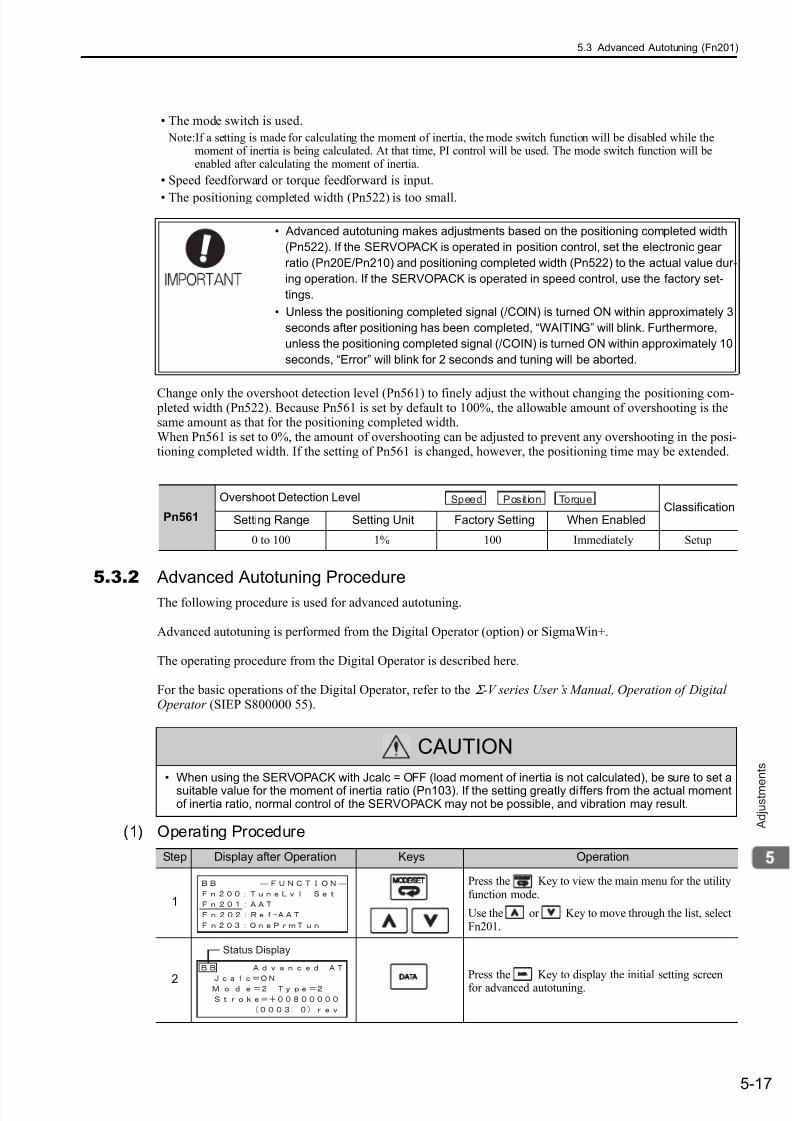
7/17/2019 Manual Yaskawa_servo_drive.pdf
http://slidepdf.com/reader/full/manual-yaskawaservodrivepdf 154/328
5.3 Advanced Autotuning (Fn201)
5-17
A d j u s t m e
n t s
• The mode switch is used.
Note:If a setting is made for calculating the moment of inertia, the mode switch function will be disabled while themoment of inertia is being calculated. At that time, PI control will be used. The mode switch function will beenabled after calculating the moment of inertia.
• Speed feedforward or torque feedforward is input.
• The positioning completed width (Pn522) is too small.
Change only the overshoot detection level (Pn561) to finely adjust the without changing the positioning com- pleted width (Pn522). Because Pn561 is set by default to 100%, the allowable amount of overshooting is thesame amount as that for the positioning completed width.When Pn561 is set to 0%, the amount of overshooting can be adjusted to prevent any overshooting in the posi-tioning completed width. If the setting of Pn561 is changed, however, the positioning time may be extended.
5.3.2 Advanced Autotuning Procedure
The following procedure is used for advanced autotuning.
Advanced autotuning is performed from the Digital Operator (option) or SigmaWin+.
The operating procedure from the Digital Operator is described here.
For the basic operations of the Digital Operator, refer to the Σ -V series User’s Manual, Operation of DigitalOperator (SIEP S800000 55).
(1) Operating Procedure
• Advanced autotuning makes adjustments based on the positioning completed width
(Pn522). If the SERVOPACK is operated in position control, set the electronic gear
ratio (Pn20E/Pn210) and positioning completed width (Pn522) to the actual value dur-
ing operation. If the SERVOPACK is operated in speed control, use the factory set-
tings.
• Unless the positioning completed signal (/COIN) is turned ON within approximately 3
seconds after positioning has been completed, “WAITING” will blink. Furthermore,
unless the positioning completed signal (/COIN) is turned ON within approximately 10
seconds, “Error” will blink for 2 seconds and tuning will be aborted.
Pn561
Overshoot Detection LevelClassification
Setting Range Setting Unit Factory Setting When Enabled
0 to 100 1% 100 Immediately Setup
Speed Position Torque
CAUTION
• When using the SERVOPACK with Jcalc = OFF (load moment of inertia is not calculated), be sure to set asuitable value for the moment of inertia ratio (Pn103). If the setting greatly differs from the actual momentof inertia ratio, normal control of the SERVOPACK may not be possible, and vibration may result.
Step Display after Operation Keys Operation
1
Press the Key to view the main menu for the utilityfunction mode.
Use the or Key to move through the list, selectFn201.
2Press the Key to display the initial setting screenfor advanced autotuning.
Status Display
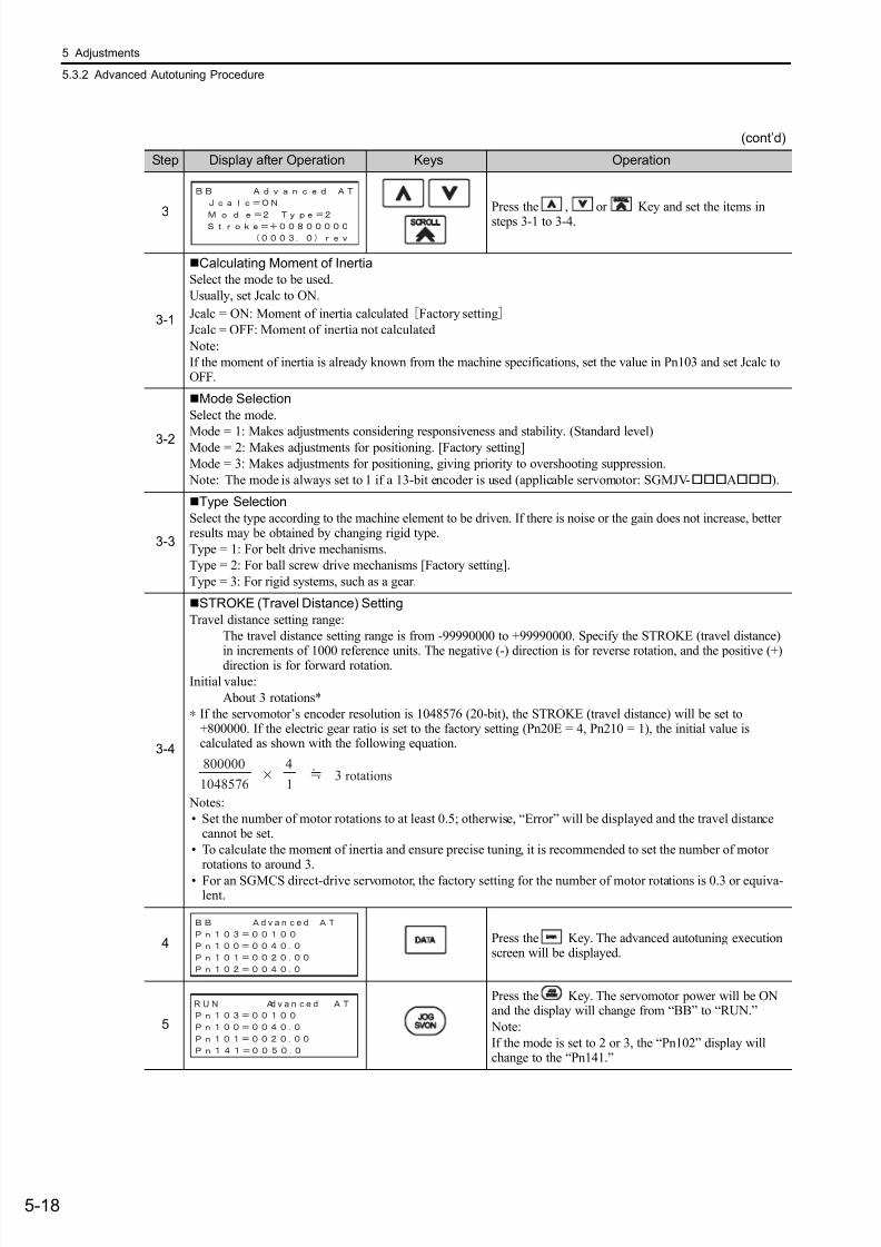
7/17/2019 Manual Yaskawa_servo_drive.pdf
http://slidepdf.com/reader/full/manual-yaskawaservodrivepdf 155/328
5 Adjustments
5.3.2 Advanced Autotuning Procedure
5-18
3
Press the , or Key and set the items in
steps 3-1 to 3-4.
3-1
Calculating Moment of Inertia
Select the mode to be used.
Usually, set Jcalc to ON.
Jcalc = ON: Moment of inertia calculated [Factory setting]
Jcalc = OFF: Moment of inertia not calculated
Note:
If the moment of inertia is already known from the machine specifications, set the value in Pn103 and set Jcalc toOFF.
3-2
Mode Selection
Select the mode.
Mode = 1: Makes adjustments considering responsiveness and stability. (Standard level)Mode = 2: Makes adjustments for positioning. [Factory setting]
Mode = 3: Makes adjustments for positioning, giving priority to overshooting suppression.
Note: The mode is always set to 1 if a 13-bit encoder is used (applicable servomotor: SGMJV-A).
3-3
Type Selection
Select the type according to the machine element to be driven. If there is noise or the gain does not increase, betterresults may be obtained by changing rigid type.
Type = 1: For belt drive mechanisms.
Type = 2: For ball screw drive mechanisms [Factory setting].
Type = 3: For rigid systems, such as a gear.
3-4
STROKE (Travel Distance) Setting
Travel distance setting range:
The travel distance setting range is from -99990000 to +99990000. Specify the STROKE (travel distance)
in increments of 1000 reference units. The negative (-) direction is for reverse rotation, and the positive (+)direction is for forward rotation.
Initial value:
About 3 rotations*
∗ If the servomotor’s encoder resolution is 1048576 (20-bit), the STROKE (travel distance) will be set to+800000. If the electric gear ratio is set to the factory setting (Pn20E = 4, Pn210 = 1), the initial value iscalculated as shown with the following equation.
Notes:
• Set the number of motor rotations to at least 0.5; otherwise, “Error” will be displayed and the travel distancecannot be set.
• To calculate the moment of inertia and ensure precise tuning, it is recommended to set the number of motorrotations to around 3.
• For an SGMCS direct-drive servomotor, the factory setting for the number of motor rotations is 0.3 or equiva-lent.
4 Press the Key. The advanced autotuning executionscreen will be displayed.
5
Press the Key. The servomotor power will be ONand the display will change from “BB” to “RUN.”
Note:
If the mode is set to 2 or 3, the “Pn102” display willchange to the “Pn141.”
(cont’d)
Step Display after Operation Keys Operation
×800000
1048576
4
13 rotations
d v a n c e d
R U N d v a n c e d
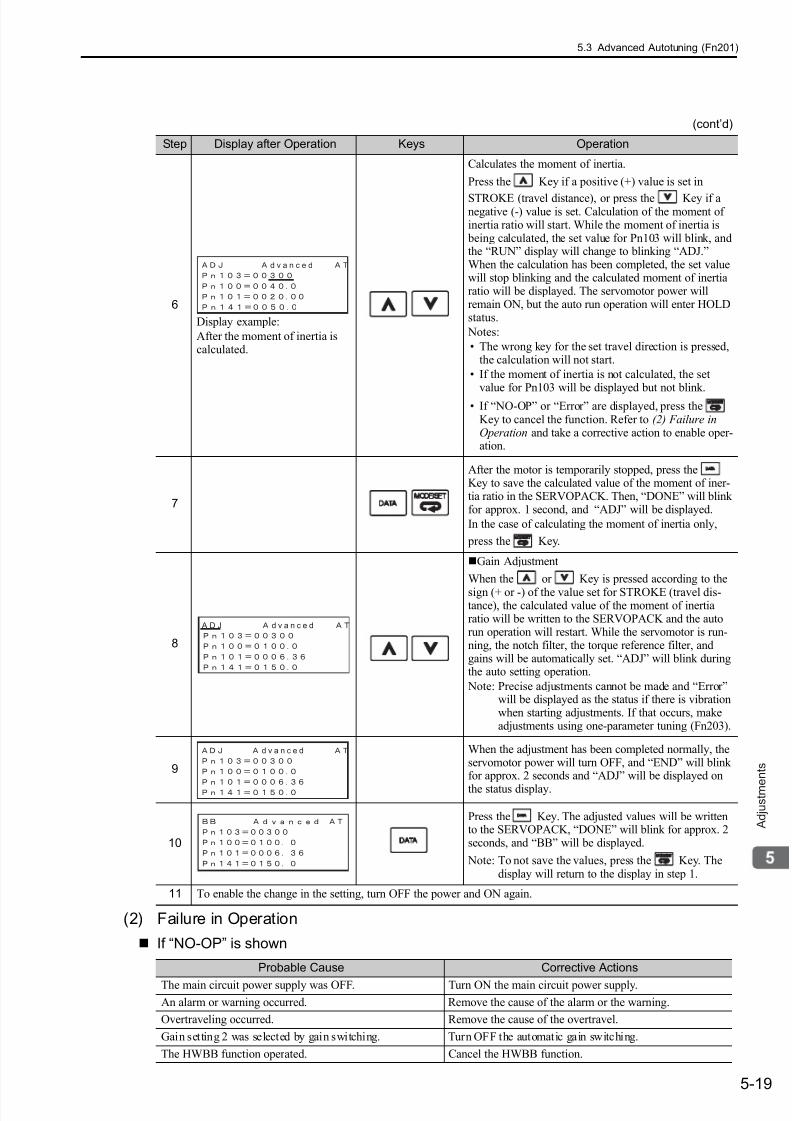
7/17/2019 Manual Yaskawa_servo_drive.pdf
http://slidepdf.com/reader/full/manual-yaskawaservodrivepdf 156/328
5.3 Advanced Autotuning (Fn201)
5-19
A d j u s t m e
n t s
(2) Failure in Operation
If “NO-OP” is shown
6
Display example:
After the moment of inertia iscalculated.
Calculates the moment of inertia.
Press the Key if a positive (+) value is set in
STROKE (travel distance), or press the Key if anegative (-) value is set. Calculation of the moment ofinertia ratio will start. While the moment of inertia is being calculated, the set value for Pn103 will blink, andthe “RUN” display will change to blinking “ADJ.”When the calculation has been completed, the set valuewill stop blinking and the calculated moment of inertiaratio will be displayed. The servomotor power willremain ON, but the auto run operation will enter HOLDstatus.
Notes:
• The wrong key for the set travel direction is pressed,the calculation will not start.
• If the moment of inertia is not calculated, the set
value for Pn103 will be displayed but not blink.• If “NO-OP” or “Error” are displayed, press the
Key to cancel the function. Refer to (2) Failure inOperation and take a corrective action to enable oper-ation.
7
After the motor is temporarily stopped, press theKey to save the calculated value of the moment of iner-tia ratio in the SERVOPACK. Then, “DONE” will blinkfor approx. 1 second, and “ADJ” will be displayed.
In the case of calculating the moment of inertia only,
press the Key.
8
Gain Adjustment
When the or Key is pressed according to the
sign (+ or -) of the value set for STROKE (travel dis-tance), the calculated value of the moment of inertiaratio will be written to the SERVOPACK and the autorun operation will restart. While the servomotor is run-ning, the notch filter, the torque reference filter, andgains will be automatically set. “ADJ” will blink duringthe auto setting operation.
Note: Precise adjustments cannot be made and “Error”will be displayed as the status if there is vibrationwhen starting adjustments. If that occurs, makeadjustments using one-parameter tuning (Fn203).
9
When the adjustment has been completed normally, theservomotor power will turn OFF, and “END” will blinkfor approx. 2 seconds and “ADJ” will be displayed on
the status display.
10
Press the Key. The adjusted values will be writtento the SERVOPACK, “DONE” will blink for approx. 2seconds, and “BB” will be displayed.
Note: To not save the values, press the Key. Thedisplay will return to the display in step 1.
11 To enable the change in the setting, turn OFF the power and ON again.
Probable Cause Corrective Actions
The main circuit power supply was OFF. Turn ON the main circuit power supply.
An alarm or warning occurred. Remove the cause of the alarm or the warning.
Overtraveling occurred. Remove the cause of the overtravel.
Gain setting 2 was selected by gain switching. Turn OFF the automatic gain switching.
The HWBB function operated. Cancel the HWBB function.
(cont’d)
Step Display after Operation Keys Operation
d v a n c e d
A D J d v a n c e d
d v a n c e d
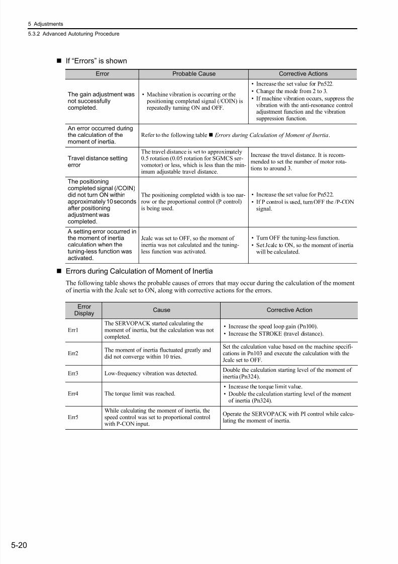
7/17/2019 Manual Yaskawa_servo_drive.pdf
http://slidepdf.com/reader/full/manual-yaskawaservodrivepdf 157/328
5 Adjustments
5.3.2 Advanced Autotuning Procedure
5-20
If “Errors” is shown
Errors during Calculation of Moment of Inertia
The following table shows the probable causes of errors that may occur during the calculation of the momentof inertia with the Jcalc set to ON, along with corrective actions for the errors.
Error Probable Cause Corrective Actions
The gain adjustment wasnot successfullycompleted.
• Machine vibration is occurring or the positioning completed signal (/COIN) isrepeatedly turning ON and OFF.
• Increase the set value for Pn522.
• Change the mode from 2 to 3.
• If machine vibration occurs, suppress thevibration with the anti-resonance controladjustment function and the vibrationsuppression function.
An error occurred duringthe calculation of themoment of inertia.
Refer to the following table Errors during Calculation of Moment of Inertia.
Travel distance settingerror
The travel distance is set to approximately0.5 rotation (0.05 rotation for SGMCS ser-vomotor) or less, which is less than the min-imum adjustable travel distance.
Increase the travel distance. It is recom-mended to set the number of motor rota-tions to around 3.
The positioningcompleted signal (/COIN)
did not turn ON withinapproximately 10 secondsafter positioningadjustment wascompleted.
The positioning completed width is too nar-row or the proportional control (P control)is being used.
• Increase the set value for Pn522.• If P control is used, turn OFF the /P-CONsignal.
A setting error occurred inthe moment of inertiacalculation when thetuning-less function wasactivated.
Jcalc was set to OFF, so the moment ofinertia was not calculated and the tuning-less function was activated.
• Turn OFF the tuning-less function.
• Set Jcalc to ON, so the moment of inertiawill be calculated.
ErrorDisplay
Cause Corrective Action
Err1The SERVOPACK started calculating themoment of inertia, but the calculation was notcompleted.
• Increase the speed loop gain (Pn100).
• Increase the STROKE (travel distance).
Err2The moment of inertia fluctuated greatly anddid not converge within 10 tries.
Set the calculation value based on the machine specifi-cations in Pn103 and execute the calculation with theJcalc set to OFF.
Err3 Low-frequency vibration was detected.Double the calculation starting level of the moment ofinertia (Pn324).
Err4 The torque limit was reached.
• Increase the torque limit value.
• Double the calculation starting level of the momentof inertia (Pn324).
Err5While calculating the moment of inertia, thespeed control was set to proportional controlwith P-CON input.
Operate the SERVOPACK with PI control while calcu-lating the moment of inertia.

7/17/2019 Manual Yaskawa_servo_drive.pdf
http://slidepdf.com/reader/full/manual-yaskawaservodrivepdf 158/328
5.3 Advanced Autotuning (Fn201)
5-21
A d j u s t m e
n t s
(3) Related Functions
Notch Filter
Usually, set this function to Auto Setting. (The notch filter is factory-set to Auto Setting.)If this function is set to Auto Setting, vibration will be detected automatically and the notch filter will be set.
Set this function to Not Auto Setting only if you do not change the notch filter setting before executingadvanced autotuning.
Anti-Resonance Control Adjustment Function
This function reduces low vibration frequency; which the notch filter does not detect.
Usually, set this function to Auto Setting. (The anti-resonance control is factory-set to Auto Setting.)
When this function is set to Auto Setting, vibration will be automatically detected during advanced autotuningand anti-resonance control will be automatically adjusted and set.
Vibration Suppression
The vibration suppression function suppresses transitional vibration at frequency as low as 1 to 100 Hz that isgenerated mainly when positioning if the machine stand vibrates.
Usually, set this function to Auto Setting. (The vibration suppression function is factory-set to Auto Setting.)
When this function is set to Auto Setting, vibration will be automatically detected during advanced autotuningand model following control with vibration suppression will be automatically adjusted and set.
Set this function to Not Auto Setting only if you do not change the setting for model following control withvibration suppression before executing advanced autotuning.
Note: This function uses model following control. Therefore, the function can be executed only if the mode is set to 2 or 3.
Related Parameters
Parameter Function When Enabled Classification
Pn460
n.0 Does not set the 1st notch filter automatically.
Immediately Tuning
n.1Sets the 1st notch filter automatically.[Factory setting]
n.0 Does not set the 2nd notch filter automatically.
n.1Sets the 2nd notch filter automatically.[Factory setting]
Parameter Function When Enabled Classification
Pn160
n.0Does not use the anti-resonance control automati-cally.
After restart Tuning
n.1Uses the anti-resonance control automatically.[Factory setting]
Parameter Function When Enabled Classification
Pn140
n.0Does not use the vibration suppression function auto-matically.
Immediately Tuning
n.1Uses the vibration suppression function automati-cally. [Factory setting]

7/17/2019 Manual Yaskawa_servo_drive.pdf
http://slidepdf.com/reader/full/manual-yaskawaservodrivepdf 159/328
5 Adjustments
5.3.2 Advanced Autotuning Procedure
5-22
Friction Compensation
This function compensates for changes in the following conditions.
• Changes in the viscous resistance of the lubricant, such as the grease, on the sliding parts of the machine
• Changes in the load resistance resulting from fluctuations in the machine assembly
• Secular changes in the load resistance
Conditions to which friction compensation is applicable depend on the mode. The friction compensation set-ting in Pn408.3 applies when the mode is 1.
Feedforward
If Pn140 is set to the factory setting and the mode setting is changed to 2 or 3, the feedforward gain (Pn109)(refer to 5.9.1) will become unavailable.
The following settings are required if model following control is used from the host controller (through thecommand option module) together with the speed feedforward input or torque feedforward input.
Mode = 1 Mode = 2 Mode = 3
Pn408
n.0
[Factorysetting]
Adjusted without the frictioncompensation function.
Adjusted with the frictioncompensation function.
Adjusted with the frictioncompensation function.
n.1Adjusted with the frictioncompensation function.
Adjusted with the frictioncompensation function.
Adjusted with the frictioncompensation function.
Mode
FrictionCompensationSelecting
• Model following control is used to make optimum feedforward settings in the servo.
Therefore, model following control from the host controller is not used together with
either the speed feedforward input or torque feedforward input. An improper speed
feedforward input or torque feedforward input may result in overshooting.
Parameter Function When Enabled Classification
Pn140
n.0Model following control is not used together withspeed/torque feedforward input.[Factory setting] Immediately Tuning
n.1Model following control is used together with speed/torque feedforward input.

7/17/2019 Manual Yaskawa_servo_drive.pdf
http://slidepdf.com/reader/full/manual-yaskawaservodrivepdf 160/328
5.3 Advanced Autotuning (Fn201)
5-23
A d j u s t m e
n t s
5.3.3 Related Parameters
The following parameters are set automatically by using advanced autotuning function.
Parameter Name
Pn100 Speed Loop Gain
Pn101 Speed Loop Integral Time Constant
Pn102 Position Loop Gain
Pn121 Friction Compensation Gain
Pn123 Friction Compensation Coefficient
Pn124 Friction Compensation Frequency Correction
Pn125 Friction Compensation Gain Correction
Pn141 Model Following Control Gain
Pn143 Model Following Control Bias (Forward Direction)
Pn144 Model Following Control Bias (Reverse Direction)
Pn145 Vibration Suppression 1 Frequency A
Pn146 Vibration Suppression 1 Frequency B
Pn147 Model Following Control Speed Feedforward Compensation
Pn161 Anti-Resonance Frequency
Pn163 Anti-Resonance Damping Gain
Pn401 1st Step 1st Torque Reference Filter Time Constant
Pn408 Notch Filter Selection/Friction Compensation Selection
Pn409 1st Notch Filter Frequency
Pn40A 1st Notch Filter Q Value
Pn40C 2nd Notch Filter Frequency
Pn40D 2nd Notch Filter Q Value

7/17/2019 Manual Yaskawa_servo_drive.pdf
http://slidepdf.com/reader/full/manual-yaskawaservodrivepdf 161/328
5 Adjustments
5.4.1 Advanced Autotuning by Reference
5-24
5.4 Advanced Autotuning by Reference (Fn202)
This section describes the adjustments with advanced autotuning by reference.
5.4.1 Advanced Autotuning by Reference
Advanced autotuning by reference is used to automatically achieve optimum tuning of the SERVOPACK inresponse to the user reference inputs from the host controller.
Advanced autotuning by reference is performed generally to fine-tune the SERVOPACK after advanced auto-tuning of the SERVOPACK has been performed.
If the load moment of inertia ratio is set correctly is Pn103, advanced autotuning by reference can be per-formed without performing advanced autotuning.
Advanced autotuning by reference performs the following adjustments.
• Gains (e.g., position loop gain and speed loop gain)
• Filters (torque reference filter and notch filter)
• Friction compensation
• Anti-resonance control
• Vibration suppression
Refer to 5.4.3 Related Parameters for parameters used for adjustments.
For information on how to input operation references, refer to the manual of the connected command optionmodule.
• Advanced autotuning by reference starts adjustments based on the set speed loopgain (Pn100). Therefore, precise adjustments cannot be made if there is vibration
when starting adjustments. In this case, make adjustments after setting a fully stable
gain using one-parameter tuning (Fn203).
CAUTION
• Because advanced autotuning by reference adjusts the SERVOPACK during automatic operation, vibra-tion or overshooting may occur. To ensure safety, perform advanced autotuning by reference in a statewhere the SERVOPACK can come to an emergency stop at any time.
• Be sure to set a suitable value for the moment of inertia ratio (Pn103) using advanced autotuning beforeadvanced autotuning by reference is performed. If the setting greatly differs from the actual moment ofinertia ratio, normal control of the SERVOPACK may not be possible, and vibration may result.
SERVOPACK
MovementSpeed
Host Controller
Reference
Response
M o v e m e n t d i s t a n c e
Reference

7/17/2019 Manual Yaskawa_servo_drive.pdf
http://slidepdf.com/reader/full/manual-yaskawaservodrivepdf 162/328
5.4 Advanced Autotuning by Reference (Fn202)
5-25
A d j u s t m e
n t s
(1) Before Performing Advanced Autotuning by Reference
Check the following settings before performing advanced autotuning by reference. The message “NO-OP”indicating that the settings are not appropriate will be displayed, if all of the following conditions are not met.
• The main circuit power supply must be ON.• There must be no overtravel.
• The servomotor power must be OFF.
• The position control must be selected when the servomotor power is ON.
• The gain selection switch must be in manual switching mode (Pn139.0 = 0).
• Gain setting 1 must be selected.
• The test without a motor function must be disabled. (Pn00C.0 = 0).
• All alarms and warnings must be cleared.
• The hardwire baseblock (HWBB) must be OFF.
• The write prohibited setting (Fn010) must not be set to write-protect parameters.
• The tuning-less function must be disabled (Pn170.0 = 0).
• The SENS_ON command is received. (when an absolute encoder is used.)
(2) When Advanced Autotuning by Reference Cannot Be Adjusted
Advanced autotuning by reference may not be performed normally under the following conditions. If theresult of autotuning is not satisfactory, perform one-parameter tuning. Refer to 5.5 One-parameter Tuning(Fn203) for details.
• The travel distance in response to references from the host controller is the same as or smaller than the set positioning completed width (Pn522).
• The motor speed in response to references from the host controller is the same as or smaller than the set rota-tion detection level (Pn502).
• The stopping time, i.e., the period while the positioning completed /COIN signal is OFF, is 10 ms or shorter.
• The rigidity of the load is low and vibration occurs when positioning is performed.
• The position integration function is used.
• P control operation (proportional control) is performed.
• The mode switch is used.
• The positioning completed width (Pn522) is too small.
Change only the overshoot detection level (Pn561) to finely adjust the without changing the positioning com- pleted width (Pn522). Because Pn561 is set by default to 100%, the allowable amount of overshooting is thesame amount as that for the positioning completed width.When Pn561 is set to 0%, the amount of overshooting can be adjusted without any overshooting in the posi-tioning completed width. If the setting of Pn561 is changed, however, the positioning time may be extended.
• Advanced autotuning by reference makes adjustments based on the positioning com-
pleted width (Pn522). Set the electronic gear ratio (Pn20E/Pn210) and positioning
completed width (Pn522) to the actual value during operation.
• Unless the positioning completed signal (/COIN) is turned ON within approximately 3
seconds after positioning has been completed, “WAITING” will blink. Furthermore,
unless the positioning completed signal (/COIN) is turned ON within approximately 10
seconds, “Error” will blink for 2 seconds and tuning will be aborted.
Pn561
Overshoot Detection LevelClassification
Setting Range Setting Unit Factory Setting When Enabled
0 to 100 1% 100 Immediately Setup
Speed Position Torque

7/17/2019 Manual Yaskawa_servo_drive.pdf
http://slidepdf.com/reader/full/manual-yaskawaservodrivepdf 163/328
5 Adjustments
5.4.2 Advanced Autotuning by Reference Procedure
5-26
5.4.2 Advanced Autotuning by Reference Procedure
The following procedure is used for advanced autotuning by reference.
Advanced autotuning by reference is performed from the Digital Operator (option) or SigmaWin+.
The operating procedure from the Digital Operator is described here.
For basic operations of the Digital Operator, refer to the Σ -V series User’s Manual, Operation of Digital Oper-ator (SIEP S800000 55).
(1) Operating Procedure
Step Display after Operation Keys Operation
1
Press the Key to view the main menu for theutility function mode.
Use the or Key to move through the list,select Fn202.
2 Press the Key to display the initial setting screenfor advanced autotuning by reference.
3 Press the or Key and set the items insteps 3-1 and 3-2.
3-1
Mode Selection
Select the mode.
Mode = 1: Makes adjustments considering responsiveness and stability. (Standard level)
Mode = 2: Makes adjustments for positioning. [Factory setting]
Mode = 3: Makes adjustments for positioning, giving priority to overshooting suppression.
Note: The mode is always set to 1 if a 13-bit encoder is used (applicable servomotor: SGMJV-A).
3-2
Type Selection
Select the type according to the machine element to be driven.
If there is noise or the gain does not increase, better results may be obtained by changing the rigid type.
Type = 1: For belt drive mechanisms.
Type = 2: For ball screw drive mechanisms [Factory setting].
Type = 3: For rigid systems, such as a gear.
4
Press the Key. The advanced autotuning execu-tion screen will be displayed.
Note: If the mode is set to 2 or 3, the “Pn102” display
will change to the “Pn141”.
5 Input a servo ON command.
6
Start to adjust using or Key. “ADJ” will blink on the status display.
Note: Adjustment cannot be performed during “BB”is shown on the status display.
7When the adjustment has been completed normally,“END” will blink for approx. 2 seconds and “ADJ”will be displayed on the status display.
Status Display
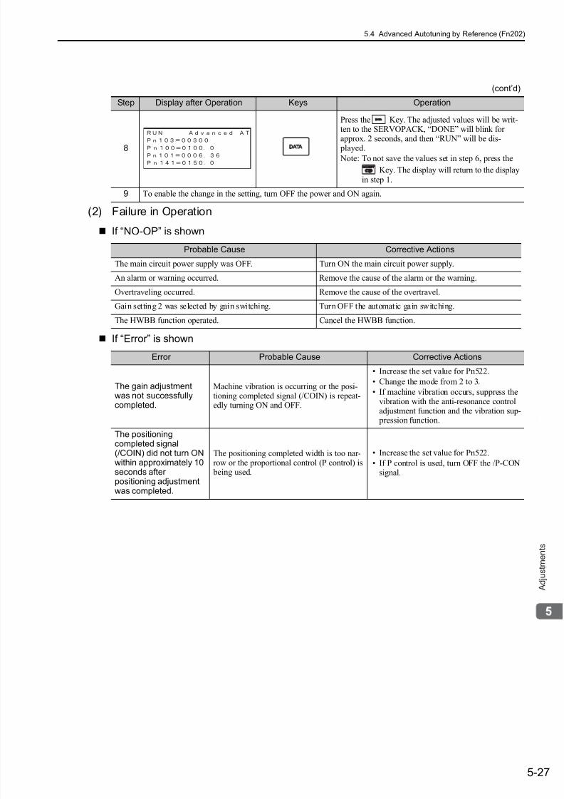
7/17/2019 Manual Yaskawa_servo_drive.pdf
http://slidepdf.com/reader/full/manual-yaskawaservodrivepdf 164/328
5.4 Advanced Autotuning by Reference (Fn202)
5-27
A d j u s t m e
n t s
(2) Failure in Operation
If “NO-OP” is shown
If “Error” is shown
8
Press the Key. The adjusted values will be writ-ten to the SERVOPACK, “DONE” will blink for
approx. 2 seconds, and then “RUN” will be dis- played.
Note: To not save the values set in step 6, press the
Key. The display will return to the displayin step 1.
9 To enable the change in the setting, turn OFF the power and ON again.
Probable Cause Corrective Actions
The main circuit power supply was OFF. Turn ON the main circuit power supply.
An alarm or warning occurred. Remove the cause of the alarm or the warning.Overtraveling occurred. Remove the cause of the overtravel.
Gain setting 2 was selected by gain switching. Turn OFF the automatic gain switching.
The HWBB function operated. Cancel the HWBB function.
Error Probable Cause Corrective Actions
The gain adjustmentwas not successfullycompleted.
Machine vibration is occurring or the posi-tioning completed signal (/COIN) is repeat-edly turning ON and OFF.
• Increase the set value for Pn522.
• Change the mode from 2 to 3.
• If machine vibration occurs, suppress thevibration with the anti-resonance controladjustment function and the vibration sup-
pression function.
The positioningcompleted signal(/COIN) did not turn ONwithin approximately 10seconds afterpositioning adjustmentwas completed.
The positioning completed width is too nar-row or the proportional control (P control) is being used.
• Increase the set value for Pn522.
• If P control is used, turn OFF the /P-CONsignal.
(cont’d)
Step Display after Operation Keys Operation
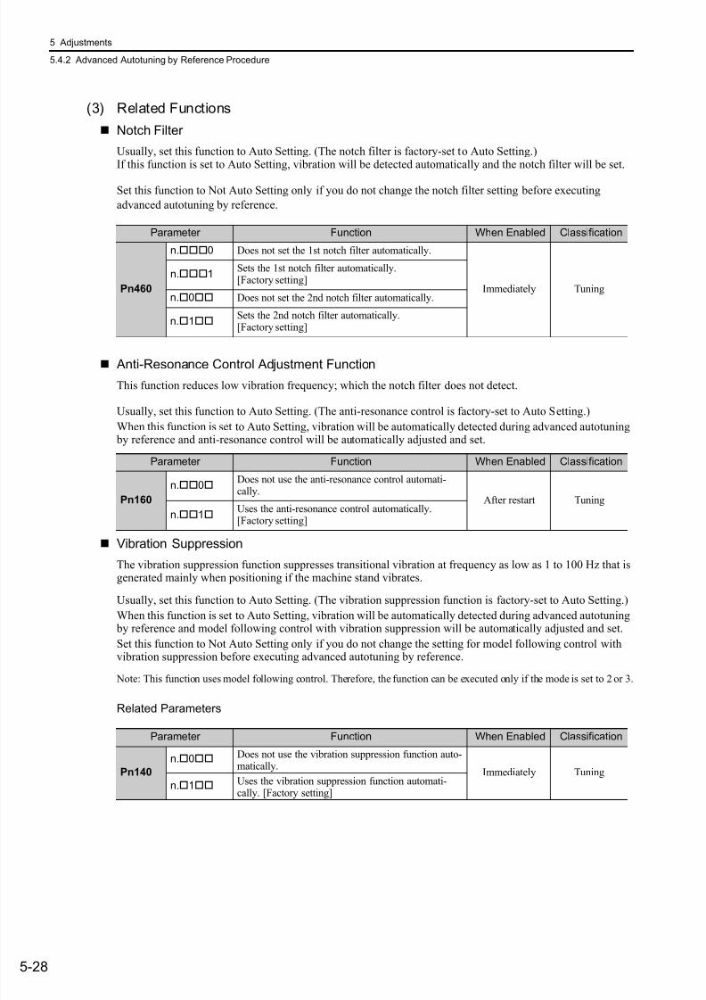
7/17/2019 Manual Yaskawa_servo_drive.pdf
http://slidepdf.com/reader/full/manual-yaskawaservodrivepdf 165/328
5 Adjustments
5.4.2 Advanced Autotuning by Reference Procedure
5-28
(3) Related Functions
Notch Filter
Usually, set this function to Auto Setting. (The notch filter is factory-set to Auto Setting.)If this function is set to Auto Setting, vibration will be detected automatically and the notch filter will be set.
Set this function to Not Auto Setting only if you do not change the notch filter setting before executing
advanced autotuning by reference.
Anti-Resonance Control Adjustment Function
This function reduces low vibration frequency; which the notch filter does not detect.
Usually, set this function to Auto Setting. (The anti-resonance control is factory-set to Auto Setting.)
When this function is set to Auto Setting, vibration will be automatically detected during advanced autotuning by reference and anti-resonance control will be automatically adjusted and set.
Vibration Suppression
The vibration suppression function suppresses transitional vibration at frequency as low as 1 to 100 Hz that isgenerated mainly when positioning if the machine stand vibrates.
Usually, set this function to Auto Setting. (The vibration suppression function is factory-set to Auto Setting.)
When this function is set to Auto Setting, vibration will be automatically detected during advanced autotuning by reference and model following control with vibration suppression will be automatically adjusted and set.
Set this function to Not Auto Setting only if you do not change the setting for model following control withvibration suppression before executing advanced autotuning by reference.
Note: This function uses model following control. Therefore, the function can be executed only if the mode is set to 2 or 3.
Related Parameters
Parameter Function When Enabled Classification
Pn460
n.0 Does not set the 1st notch filter automatically.
Immediately Tuning
n.1Sets the 1st notch filter automatically.[Factory setting]
n.0 Does not set the 2nd notch filter automatically.
n.1Sets the 2nd notch filter automatically.[Factory setting]
Parameter Function When Enabled Classification
Pn160
n.0Does not use the anti-resonance control automati-cally.
After restart Tuning
n.1Uses the anti-resonance control automatically.
[Factory setting]
Parameter Function When Enabled Classification
Pn140
n.0 Does not use the vibration suppression function auto-matically.
Immediately Tuning
n.1 Uses the vibration suppression function automati-cally. [Factory setting]
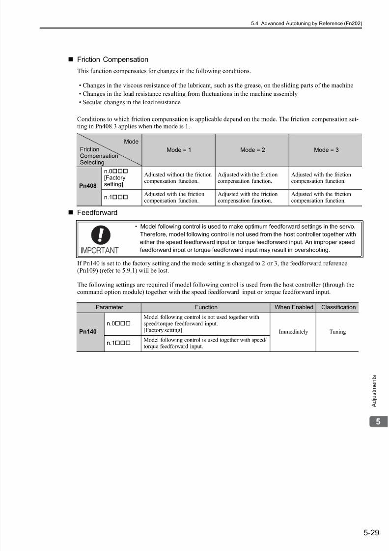
7/17/2019 Manual Yaskawa_servo_drive.pdf
http://slidepdf.com/reader/full/manual-yaskawaservodrivepdf 166/328
5.4 Advanced Autotuning by Reference (Fn202)
5-29
A d j u s t m e
n t s
Friction Compensation
This function compensates for changes in the following conditions.
• Changes in the viscous resistance of the lubricant, such as the grease, on the sliding parts of the machine
• Changes in the load resistance resulting from fluctuations in the machine assembly• Secular changes in the load resistance
Conditions to which friction compensation is applicable depend on the mode. The friction compensation set-ting in Pn408.3 applies when the mode is 1.
Feedforward
If Pn140 is set to the factory setting and the mode setting is changed to 2 or 3, the feedforward reference(Pn109) (refer to 5.9.1) will be lost.
The following settings are required if model following control is used from the host controller (through thecommand option module) together with the speed feedforward input or torque feedforward input.
Mode = 1 Mode = 2 Mode = 3
Pn408
n.0[Factorysetting]
Adjusted without the frictioncompensation function.
Adjusted with the frictioncompensation function.
Adjusted with the frictioncompensation function.
n.1 Adjusted with the frictioncompensation function.
Adjusted with the frictioncompensation function.
Adjusted with the frictioncompensation function.
• Model following control is used to make optimum feedforward settings in the servo.
Therefore, model following control is not used from the host controller together with
either the speed feedforward input or torque feedforward input. An improper speed
feedforward input or torque feedforward input may result in overshooting.
Mode
FrictionCompensationSelecting
Parameter Function When Enabled Classification
Pn140
n.0Model following control is not used together withspeed/torque feedforward input.[Factory setting] Immediately Tuning
n.1Model following control is used together with speed/torque feedforward input.
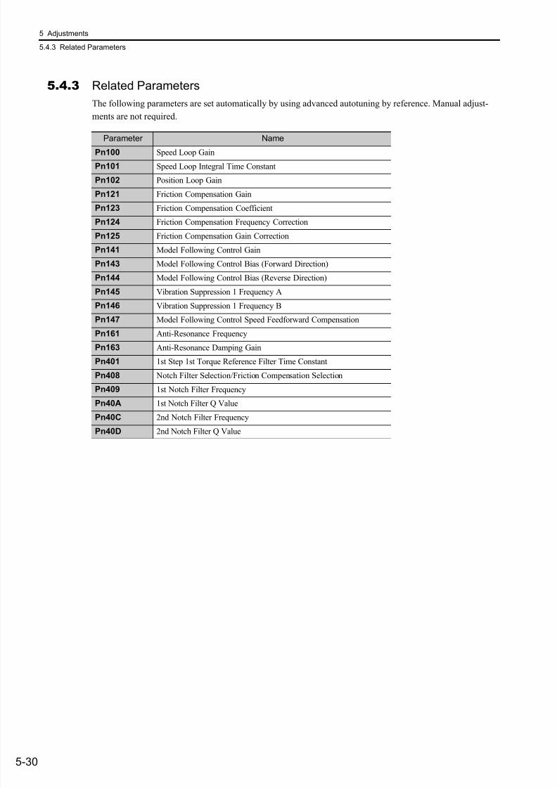
7/17/2019 Manual Yaskawa_servo_drive.pdf
http://slidepdf.com/reader/full/manual-yaskawaservodrivepdf 167/328
5 Adjustments
5.4.3 Related Parameters
5-30
5.4.3 Related Parameters
The following parameters are set automatically by using advanced autotuning by reference. Manual adjust-
ments are not required.
Parameter Name
Pn100 Speed Loop Gain
Pn101 Speed Loop Integral Time Constant
Pn102 Position Loop Gain
Pn121 Friction Compensation Gain
Pn123 Friction Compensation Coefficient
Pn124 Friction Compensation Frequency Correction
Pn125 Friction Compensation Gain Correction
Pn141 Model Following Control Gain
Pn143 Model Following Control Bias (Forward Direction)
Pn144 Model Following Control Bias (Reverse Direction)
Pn145 Vibration Suppression 1 Frequency A
Pn146 Vibration Suppression 1 Frequency B
Pn147 Model Following Control Speed Feedforward Compensation
Pn161 Anti-Resonance Frequency
Pn163 Anti-Resonance Damping Gain
Pn401 1st Step 1st Torque Reference Filter Time Constant
Pn408 Notch Filter Selection/Friction Compensation Selection
Pn409 1st Notch Filter Frequency
Pn40A 1st Notch Filter Q Value
Pn40C 2nd Notch Filter Frequency
Pn40D 2nd Notch Filter Q Value
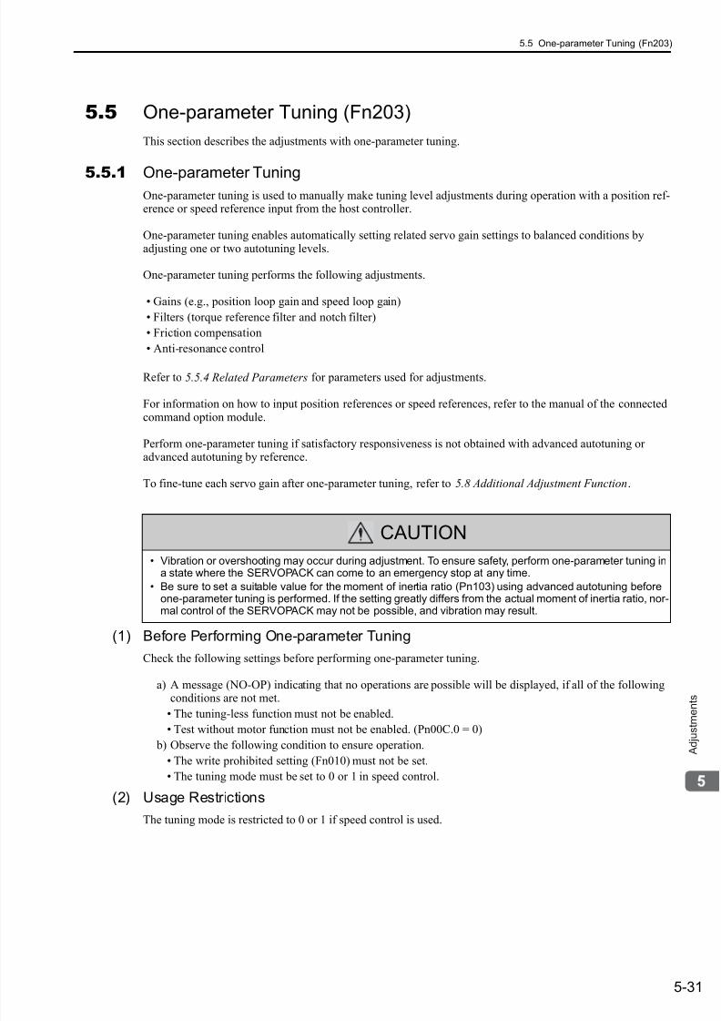
7/17/2019 Manual Yaskawa_servo_drive.pdf
http://slidepdf.com/reader/full/manual-yaskawaservodrivepdf 168/328
5.5 One-parameter Tuning (Fn203)
5-31
A d j u s t m e
n t s
5.5 One-parameter Tuning (Fn203)
This section describes the adjustments with one-parameter tuning.
5.5.1One-parameter TuningOne-parameter tuning is used to manually make tuning level adjustments during operation with a position ref-erence or speed reference input from the host controller.
One-parameter tuning enables automatically setting related servo gain settings to balanced conditions byadjusting one or two autotuning levels.
One-parameter tuning performs the following adjustments.
• Gains (e.g., position loop gain and speed loop gain)
• Filters (torque reference filter and notch filter)
• Friction compensation
• Anti-resonance control
Refer to 5.5.4 Related Parameters for parameters used for adjustments.
For information on how to input position references or speed references, refer to the manual of the connectedcommand option module.
Perform one-parameter tuning if satisfactory responsiveness is not obtained with advanced autotuning oradvanced autotuning by reference.
To fine-tune each servo gain after one-parameter tuning, refer to 5.8 Additional Adjustment Function.
(1) Before Performing One-parameter Tuning
Check the following settings before performing one-parameter tuning.
a) A message (NO-OP) indicating that no operations are possible will be displayed, if all of the followingconditions are not met.
• The tuning-less function must not be enabled.• Test without motor function must not be enabled. (Pn00C.0 = 0)
b) Observe the following condition to ensure operation.
• The write prohibited setting (Fn010) must not be set.
• The tuning mode must be set to 0 or 1 in speed control.
(2) Usage Restrictions
The tuning mode is restricted to 0 or 1 if speed control is used.
CAUTION• Vibration or overshooting may occur during adjustment. To ensure safety, perform one-parameter tuning in
a state where the SERVOPACK can come to an emergency stop at any time.
• Be sure to set a suitable value for the moment of inertia ratio (Pn103) using advanced autotuning beforeone-parameter tuning is performed. If the setting greatly differs from the actual moment of inertia ratio, nor-mal control of the SERVOPACK may not be possible, and vibration may result.
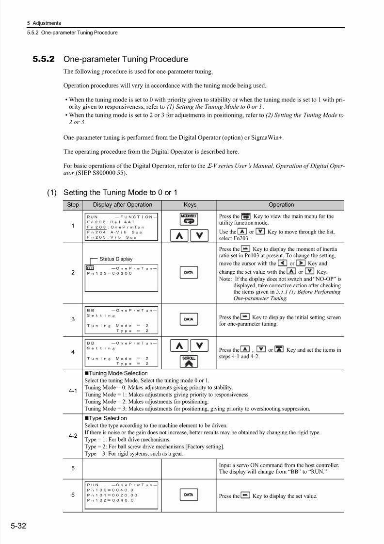
7/17/2019 Manual Yaskawa_servo_drive.pdf
http://slidepdf.com/reader/full/manual-yaskawaservodrivepdf 169/328
5 Adjustments
5.5.2 One-parameter Tuning Procedure
5-32
5.5.2 One-parameter Tuning Procedure
The following procedure is used for one-parameter tuning.
Operation procedures will vary in accordance with the tuning mode being used.
• When the tuning mode is set to 0 with priority given to stability or when the tuning mode is set to 1 with pri-ority given to responsiveness, refer to (1) Setting the Tuning Mode to 0 or 1.
• When the tuning mode is set to 2 or 3 for adjustments in positioning, refer to (2) Setting the Tuning Mode to2 or 3.
One-parameter tuning is performed from the Digital Operator (option) or SigmaWin+.
The operating procedure from the Digital Operator is described here.
For basic operations of the Digital Operator, refer to the Σ -V series User’s Manual, Operation of Digital Oper-ator (SIEP S800000 55).
(1) Setting the Tuning Mode to 0 or 1
Step Display after Operation Keys Operation
1
Press the Key to view the main menu for theutility function mode.
Use the or Key to move through the list,select Fn203.
2
Press the Key to display the moment of inertiaratio set in Pn103 at present. To change the setting,
move the cursor with the or Key and
change the set value with the or Key.
Note: If the display does not switch and “NO-OP” is
displayed, take corrective action after checkingthe items given in 5.5.1 (1) Before PerformingOne-parameter Tuning.
3 Press the Key to display the initial setting screenfor one-parameter tuning.
4 Press the , or Key and set the items insteps 4-1 and 4-2.
4-1
Tuning Mode Selection
Select the tuning Mode. Select the tuning mode 0 or 1.Tuning Mode = 0: Makes adjustments giving priority to stability.
Tuning Mode = 1: Makes adjustments giving priority to responsiveness.
Tuning Mode = 2: Makes adjustments for positioning.
Tuning Mode = 3: Makes adjustments for positioning, giving priority to overshooting suppression.
4-2
Type Selection
Select the type according to the machine element to be driven.
If there is noise or the gain does not increase, better results may be obtained by changing the rigid type.
Type = 1: For belt drive mechanisms.
Type = 2: For ball screw drive mechanisms [Factory setting].
Type = 3: For rigid systems, such as a gear.
5Input a servo ON command from the host controller.The display will change from “BB” to “RUN.”
6 Press the Key to display the set value.
Status Display

7/17/2019 Manual Yaskawa_servo_drive.pdf
http://slidepdf.com/reader/full/manual-yaskawaservodrivepdf 170/328
5.5 One-parameter Tuning (Fn203)
5-33
A d j u s t m e
n t s
7
Adjust the responsiveness by changing the level.
After pressing the Key, the present level will be
displayed. Move the cursor with the orKeys and adjust the level with or Keys, and
press the Key.
The higher the level, the greater the responsivenesswill be. If the value is too large, however, vibrationwill occur.
If that occurs, press the Key. The SERVOPACKwill automatically detect the vibration frequenciesand make notch filter or anti-resonance control set-tings.
When the notch filter is set, “NF1” or “NF2” will bedisplayed on the bottom row.
When anti-resonance control is set, “ARES” is dis- played.
Note: If the vibration is great, the vibration frequencywill be detected even if the Key is not pressed and a notch filter or anti-resonancecontrol will be set.
8 Press the Key. A confirmation screen is dis- played after level adjustment.
9
• Press the Key. The adjusted values will bewritten to the SERVOPACK. “DONE” will be dis- played for approx. 2 seconds, and then “RUN” will be displayed.
• Not to save the values set in step 7, press the
Key.
• The screen in step 7 will appear with the Key.
10Press the Key to complete the one-parametertuning operation. The screen in step 1 will appearagain.
(cont’d)
Step Display after Operation Keys Operation

7/17/2019 Manual Yaskawa_servo_drive.pdf
http://slidepdf.com/reader/full/manual-yaskawaservodrivepdf 171/328
5 Adjustments
5.5.2 One-parameter Tuning Procedure
5-34
(2) Setting the Tuning Mode to 2 or 3
Step Display after Operation Keys Operation
1
Press the Key to view the main menu for theutility function mode.
Use the or Key to move through the list,select Fn203.
2
Press the Key to display the moment of inertiaratio set in Pn103 at present. To change the setting,
move the cursor with the or Key and
change the set value with the or Key.
Note: If the display does not switch and “NO-OP” isdisplayed, take corrective action after checkingthe items given in 5.5.1 (1) Before PerformingOne-parameter Tuning.
3 Press the Key to display the initial setting screen
for one-parameter tuning.
4 Press the , or Key and set the items insteps 4-1 and 4-2.
4-1
Tuning Mode Selection
Select the tuning Mode. Select the tuning mode 2 or 3.
Tuning Mode = 0: Makes adjustments giving priority to stability.
Tuning Mode = 1: Makes adjustments giving priority to responsiveness.
Tuning Mode = 2: Makes adjustments for positioning.
Tuning Mode = 3: Makes adjustments for positioning, giving priority to overshooting suppression.
4-2
Type SelectionSelect the type according to the machine element to be driven.
If there is noise or the gain does not increase, better results may be obtained by changing the rigid type.
Type = 1: For belt drive mechanisms.
Type = 2: For ball screw drive mechanisms [Factory setting].
Type = 3: For rigid systems, such as a gear.
5Input an servo ON command from the host controller.The display will change from “BB” to “RUN.”
6 Press the Key to display the set value.
Status Display
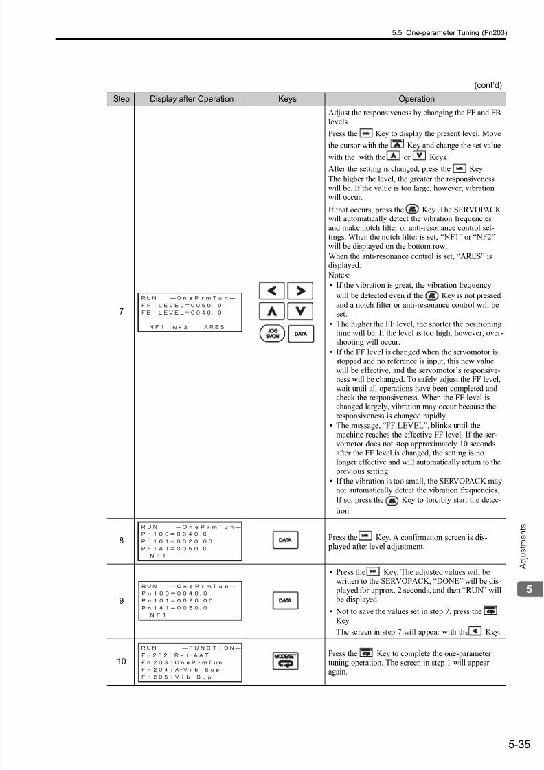
7/17/2019 Manual Yaskawa_servo_drive.pdf
http://slidepdf.com/reader/full/manual-yaskawaservodrivepdf 172/328
5.5 One-parameter Tuning (Fn203)
5-35
A d j u s t m e
n t s
7
Adjust the responsiveness by changing the FF and FBlevels.
Press the Key to display the present level. Movethe cursor with the Key and change the set value
with the with the or Keys.
After the setting is changed, press the Key.
The higher the level, the greater the responsivenesswill be. If the value is too large, however, vibrationwill occur.
If that occurs, press the Key. The SERVOPACKwill automatically detect the vibration frequenciesand make notch filter or anti-resonance control set-tings. When the notch filter is set, “NF1” or “NF2”will be displayed on the bottom row.
When the anti-resonance control is set, “ARES” isdisplayed.
Notes:
• If the vibration is great, the vibration frequency
will be detected even if the Key is not pressedand a notch filter or anti-resonance control will beset.
• The higher the FF level, the shorter the positioningtime will be. If the level is too high, however, over-shooting will occur.
• If the FF level is changed when the servomotor isstopped and no reference is input, this new valuewill be effective, and the servomotor’s responsive-ness will be changed. To safely adjust the FF level,wait until all operations have been completed andcheck the responsiveness. When the FF level is
changed largely, vibration may occur because theresponsiveness is changed rapidly.
• The message, “FF LEVEL”, blinks until themachine reaches the effective FF level. If the ser-vomotor does not stop approximately 10 secondsafter the FF level is changed, the setting is nolonger effective and will automatically return to the previous setting.
• If the vibration is too small, the SERVOPACK maynot automatically detect the vibration frequencies.
If so, press the Key to forcibly start the detec-
tion.
8 Press the Key. A confirmation screen is dis- played after level adjustment.
9
• Press the Key. The adjusted values will bewritten to the SERVOPACK, “DONE” will be dis- played for approx. 2 seconds, and then “RUN” will be displayed.
• Not to save the values set in step 7, press theKey.
The screen in step 7 will appear with the Key.
10Press the Key to complete the one-parametertuning operation. The screen in step 1 will appear
again.
(cont’d)
Step Display after Operation Keys Operation
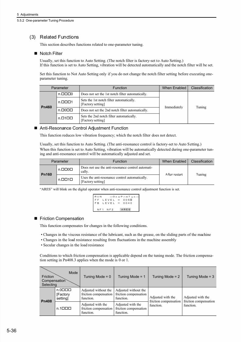
7/17/2019 Manual Yaskawa_servo_drive.pdf
http://slidepdf.com/reader/full/manual-yaskawaservodrivepdf 173/328
5 Adjustments
5.5.2 One-parameter Tuning Procedure
5-36
(3) Related Functions
This section describes functions related to one-parameter tuning.
Notch Filter
Usually, set this function to Auto Setting. (The notch filter is factory-set to Auto Setting.)If this function is set to Auto Setting, vibration will be detected automatically and the notch filter will be set.
Set this function to Not Auto Setting only if you do not change the notch filter setting before executing one- parameter tuning.
Anti-Resonance Control Adjustment Function
This function reduces low vibration frequency; which the notch filter does not detect.
Usually, set this function to Auto Setting. (The anti-resonance control is factory-set to Auto Setting.)
When this function is set to Auto Setting, vibration will be automatically detected during one-parameter tun-ing and anti-resonance control will be automatically adjusted and set.
“ARES” will blink on the digital operator when anti-resonance control adjustment function is set.
Friction Compensation
This function compensates for changes in the following conditions.
• Changes in the viscous resistance of the lubricant, such as the grease, on the sliding parts of the machine
• Changes in the load resistance resulting from fluctuations in the machine assembly• Secular changes in the load resistance
Conditions to which friction compensation is applicable depend on the tuning mode. The friction compensa-tion setting in Pn408.3 applies when the mode is 0 or 1.
Parameter Function When Enabled Classification
Pn460
n.0 Does not set the 1st notch filter automatically.
Immediately Tuning
n.1Sets the 1st notch filter automatically.[Factory setting]
n.0 Does not set the 2nd notch filter automatically.
n.
1
Sets the 2nd notch filter automatically.
[Factory setting]
Parameter Function When Enabled Classification
Pn160
n.0Does not use the anti-resonance control automati-cally.
After restart Tuning
n.1Uses the anti-resonance control automatically.[Factory setting]
Tuning Mode = 0 Tuning Mode = 1 Tuning Mode = 2 Tuning Mode = 3
Pn408
n.0
[Factory
setting]
Adjusted without thefriction compensation
function.
Adjusted without thefriction compensation
function.Adjusted with thefriction compensationfunction.
Adjusted with thefriction compensationfunction.
n.1Adjusted with thefriction compensationfunction.
Adjusted with thefriction compensationfunction.
ModeFrictionCompensationSelecting
7/17/2019 Manual Yaskawa_servo_drive.pdf
http://slidepdf.com/reader/full/manual-yaskawaservodrivepdf 174/328
5.5 One-parameter Tuning (Fn203)
5-37
A d j u s t m e
n t s
Feedforward
If Pn140 is set to the factory setting and the mode setting is changed to 2 or 3, the feedforward gain (Pn109)(refer to 5.9.1) will be lost.
The following settings are required if model following control is used from the host controller (through thecommand option module) together with speed feedforward input or torque feedforward input.
• Model following control is used to make optimum feedforward settings in the servo.
Therefore, model following control from the host controller is not used together with
either the speed feedforward input or torque feedforward input. An improper speed
feedforward input or torque feedforward input may result in overshooting.
Parameter Function When Enabled Classification
Pn140
n.0Model following control is not used together withspeed/torque feedforward input.[Factory setting] Immediately Tuning
n.1Model following control is used together with speed/torque feedforward input.
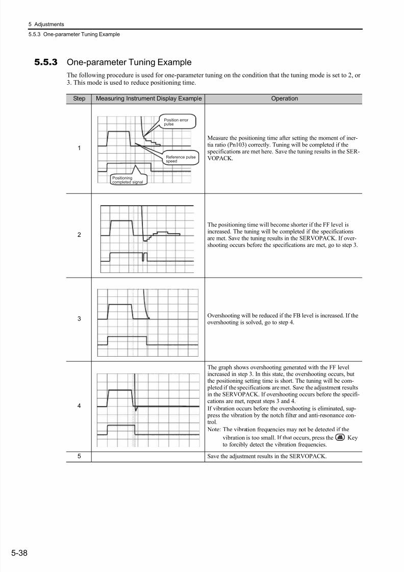
7/17/2019 Manual Yaskawa_servo_drive.pdf
http://slidepdf.com/reader/full/manual-yaskawaservodrivepdf 175/328
5 Adjustments
5.5.3 One-parameter Tuning Example
5-38
5.5.3 One-parameter Tuning Example
The following procedure is used for one-parameter tuning on the condition that the tuning mode is set to 2, or3. This mode is used to reduce positioning time.
Step Measuring Instrument Display Example Operation
1
Measure the positioning time after setting the moment of iner-tia ratio (Pn103) correctly. Tuning will be completed if thespecifications are met here. Save the tuning results in the SER-VOPACK.
2
The positioning time will become shorter if the FF level isincreased. The tuning will be completed if the specificationsare met. Save the tuning results in the SERVOPACK. If over-shooting occurs before the specifications are met, go to step 3.
3Overshooting will be reduced if the FB level is increased. If theovershooting is solved, go to step 4.
4
The graph shows overshooting generated with the FF levelincreased in step 3. In this state, the overshooting occurs, butthe positioning setting time is short. The tuning will be com- pleted if the specifications are met. Save the adjustment resultsin the SERVOPACK. If overshooting occurs before the specifi-
cations are met, repeat steps 3 and 4.If vibration occurs before the overshooting is eliminated, sup- press the vibration by the notch filter and anti-resonance con-trol.
Note: The vibration frequencies may not be detected if the
vibration is too small. If that occurs, press the Keyto forcibly detect the vibration frequencies.
5 Save the adjustment results in the SERVOPACK.
Positioningcompleted signal
Reference pulsespeed
Position errorpulse
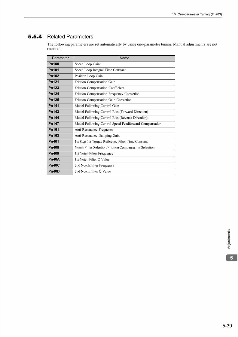
7/17/2019 Manual Yaskawa_servo_drive.pdf
http://slidepdf.com/reader/full/manual-yaskawaservodrivepdf 176/328
5.5 One-parameter Tuning (Fn203)
5-39
A d j u s t m e
n t s
5.5.4 Related Parameters
The following parameters are set automatically by using one-parameter tuning. Manual adjustments are notrequired.
Parameter NamePn100 Speed Loop Gain
Pn101 Speed Loop Integral Time Constant
Pn102 Position Loop Gain
Pn121 Friction Compensation Gain
Pn123 Friction Compensation Coefficient
Pn124 Friction Compensation Frequency Correction
Pn125 Friction Compensation Gain Correction
Pn141 Model Following Control Gain
Pn143 Model Following Control Bias (Forward Direction)
Pn144 Model Following Control Bias (Reverse Direction)
Pn147 Model Following Control Speed Feedforward Compensation
Pn161 Anti-Resonance Frequency
Pn163 Anti-Resonance Damping Gain
Pn401 1st Step 1st Torque Reference Filter Time Constant
Pn408 Notch Filter Selection/Friction Compensation Selection
Pn409 1st Notch Filter Frequency
Pn40A 1st Notch Filter Q Value
Pn40C 2nd Notch Filter Frequency
Pn40D 2nd Notch Filter Q Value
7/17/2019 Manual Yaskawa_servo_drive.pdf
http://slidepdf.com/reader/full/manual-yaskawaservodrivepdf 177/328
5 Adjustments
5.6.1 Anti-resonance Control Adjustment Function
5-40
5.6 Anti-resonance Control Adjustment Function (Fn204)
This section describes how to adjust the anti-resonance control.
5.6.1 Anti-resonance Control Adjustment FunctionThe anti-resonance control adjustment function increases the effectiveness of the vibration suppression afterone-parameter tuning.
The anti-resonance control adjustment function (Pn204) is an effective way to control the frequent vibration between 100 Hz and 1000 Hz when the control gain increases.
Perform one-parameter tuning (Fn203) or use another method to increase the responsiveness after performingthis function. If the vibration gain is increased with one-parameter tuning performed, vibration may resultagain. If that occurs, perform this function again to fine-tune the settings.
(1) Before Performing Anti-Resonance Control Adjustment Function
Check the following settings before performing anti-resonance control adjustment function.
a) A message (NO-OP) indicating that no operations are possible will be displayed, if all of the followingconditions are not met.
• The tuning-less function must not be enabled.
• Test without motor function must not be enabled. (Pn00C.0=0)
• Torque control must not be selected.
b) Observe the following condition to ensure operation.
• The write prohibited setting (Fn010) must not be set.
CAUTION• If this function is executed, related parameters will be set automatically. Therefore, there will be a large
response change after this function is enabled or disabled. Enable the function in a state where themachine can come to an emergency stop at any time to ensure the safety operation of the machine.
• Be sure to set a suitable value for the moment of inertia ratio (Pn103) using advanced autotuning beforeexecuting the anti-resonance control adjustment function. If the setting greatly differs from the actualmoment of inertia ratio, normal control of the SERVOPACK may not be possible, and vibration may result.
• This function detects vibration between 100 and 1,000 Hz. Vibration will not be
detected for frequencies outside of this range, and instead, “F----” will be displayed. If
that occurs, use one-parameter tuning with tuning mode 2 selected to automatically
set a notch filter or use the vibration suppression function (Fn205).
• Vibration can be reduced more effectively by increasing the present damping gain(Pn163). The amplitude of vibration may become larger if the damping gain is exces-
sively high. Increase the vibration gain from about 0% to 200% in 10% increments
while checking the effect of vibration reduction. If the effect of vibration reduction is
still insufficient at a gain of 200%, cancel the setting, and lower the control gain using
a different method, such as one-parameter tuning.
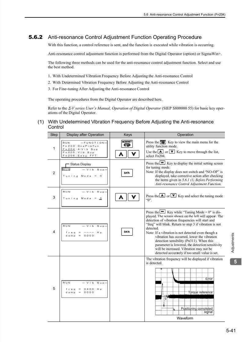
7/17/2019 Manual Yaskawa_servo_drive.pdf
http://slidepdf.com/reader/full/manual-yaskawaservodrivepdf 178/328
5.6 Anti-resonance Control Adjustment Function (Fn204)
5-41
A d j u s t m e
n t s
5.6.2 Anti-resonance Control Adjustment Function Operating Procedure
With this function, a control reference is sent, and the function is executed while vibration is occurring.
Anti-resonance control adjustment function is performed from the Digital Operator (option) or SigmaWin+.
The following three methods can be used for the anti-resonance control adjustment function. Select and usethe best method.
1. With Undetermined Vibration Frequency Before Adjusting the Anti-resonance Control
2. With Determined Vibration Frequency Before Adjusting the Anti-resonance Control
3. For Fine-tuning After Adjusting the Anti-resonance Control
The operating procedures from the Digital Operator are described here.
Refer to the Σ -V series User’s Manual, Operation of Digital Operator (SIEP S800000 55) for basic key oper-ations of the Digital Operator.
(1) With Undetermined Vibration Frequency Before Adjusting the Anti-resonanceControl
Step Display after Operation Keys Operation
1
Press the Key to view the main menu for theutility function mode.
Use the or Key to move through the list,select Fn204.
2
Press the Key to display the initial setting screenfor tuning mode.
Note: If the display does not switch and “NO-OP” isdisplayed, take corrective action after checking
the items given in 5.6.1 (1) Before Performing Anti-resonance Control Adjustment Function.
3 Press the or Key and select the tuning mode“0”.
4
Press the Key while “Tuning Mode = 0" is dis- played. The screen shown on the left will appear. Thedetection of vibration frequencies will start and“freq” will blink. Return to step 3 if vibration is notdetected.
Note: If a vibration is not detected even though avibration has occurred, lower the vibration
detection sensibility (Pn311). When this parameter is lowered, the detection sensitivitywill be increased. Vibration may not bedetected accurately if too small value is set.
5
The vibration frequency will be displayed if vibrationis detected.
Waveform
Status Display
Error rrorError
Torque reference
Positioning completedositioning completed
signalignal
Torque reference
Positioning completedsignal
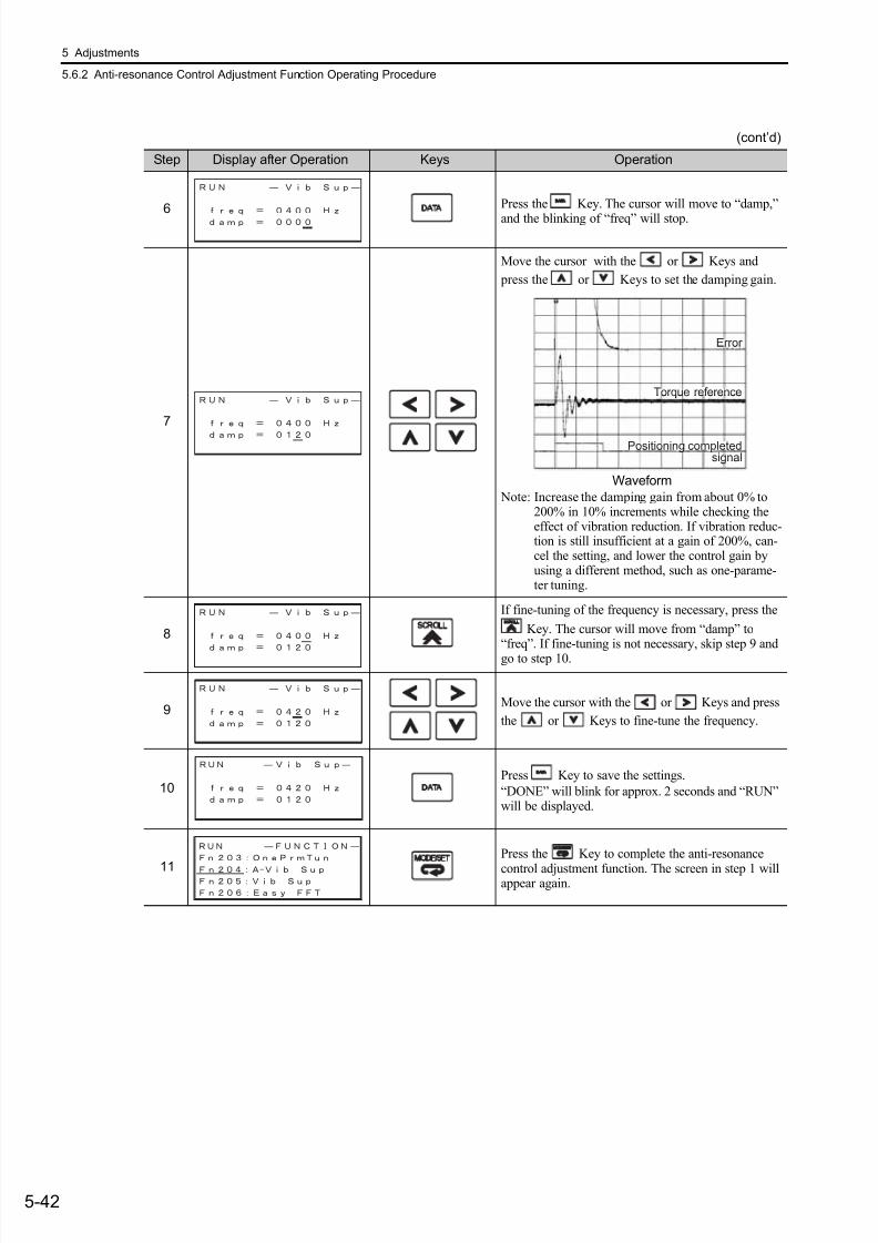
7/17/2019 Manual Yaskawa_servo_drive.pdf
http://slidepdf.com/reader/full/manual-yaskawaservodrivepdf 179/328
5 Adjustments
5.6.2 Anti-resonance Control Adjustment Function Operating Procedure
5-42
6 Press the Key. The cursor will move to “damp,”
and the blinking of “freq” will stop.
7
Move the cursor with the or Keys and
press the or Keys to set the damping gain.
Waveform
Note: Increase the damping gain from about 0% to200% in 10% increments while checking theeffect of vibration reduction. If vibration reduc-tion is still insufficient at a gain of 200%, can-cel the setting, and lower the control gain byusing a different method, such as one-parame-ter tuning.
8
If fine-tuning of the frequency is necessary, press the
Key. The cursor will move from “damp” to“freq”. If fine-tuning is not necessary, skip step 9 andgo to step 10.
9Move the cursor with the or Keys and press
the or Keys to fine-tune the frequency.
10Press Key to save the settings.
“DONE” will blink for approx. 2 seconds and “RUN”will be displayed.
11
Press the Key to complete the anti-resonance
control adjustment function. The screen in step 1 willappear again.
(cont’d)
Step Display after Operation Keys Operation
Error rror
Torque referenceorque reference
Positioning completedositioning completed
signalignal
Error
Torque reference
Positioning completedsignal
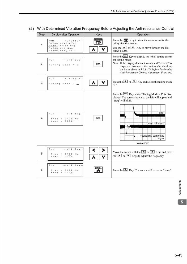
7/17/2019 Manual Yaskawa_servo_drive.pdf
http://slidepdf.com/reader/full/manual-yaskawaservodrivepdf 180/328
5.6 Anti-resonance Control Adjustment Function (Fn204)
5-43
A d j u s t m e
n t s
(2) With Determined Vibration Frequency Before Adjusting the Anti-resonance Control
Step Display after Operation Keys Operation
1
Press the Key to view the main menu for theutility function mode.
Use the or Key to move through the list,select Fn204.
2
Press the Key to display the initial setting screenfor tuning mode.
Note: If the display does not switch and “NO-OP” isdisplayed, take corrective action after checkingthe items given in 5.6.1 (1) Before Performing Anti-Resonance Control Adjustment Function.
3 Press the or Key and select the tuning mode“1”.
4
Press the Key while “Tuning Mode = 1" is dis- played. The screen shown on the left will appear and“freq” will blink.
Waveform
5Move the cursor with the or Keys and press
the or Keys to adjust the frequency.
6 Press the Key. The cursor will move to “damp”.
Error rrorError
Torque reference
Positioning completedositioning completed
signalignal
Torque reference
Positioning completed
signal

7/17/2019 Manual Yaskawa_servo_drive.pdf
http://slidepdf.com/reader/full/manual-yaskawaservodrivepdf 181/328
5 Adjustments
5.6.2 Anti-resonance Control Adjustment Function Operating Procedure
5-44
7
Move the cursor with the or Key and press
the or Key to adjust the damping gain.
Waveform
Note: Increase the damping gain from about 0% to
200% in 10% increments while checking theeffect of vibration reduction. If vibration reduc-tion is still insufficient at a gain of 200%, can-cel the setting, and lower the control gain byusing a different method, such as one-parame-ter tuning.
8
If fine-tuning of the frequency is necessary, press the
Key. The cursor will move from “damp” to“freq”. If fine-tuning is not necessary, skip step 9 andgo to step 10.
9Move the cursor with or Keys and press the
or Keys to fine-tune the frequency.
10Press Key to save the settings.
“DONE” will blink for approx. 2 seconds and “RUN”will be displayed.
11Press the Key to complete the anti-resonancecontrol adjustment function. The screen in step 1 willappear again.
(cont’d)
Step Display after Operation Keys Operation
Error rror
Torque referenceorque reference
Positioning completedositioning completed
signalignal
Error
Torque reference
Positioning completedsignal
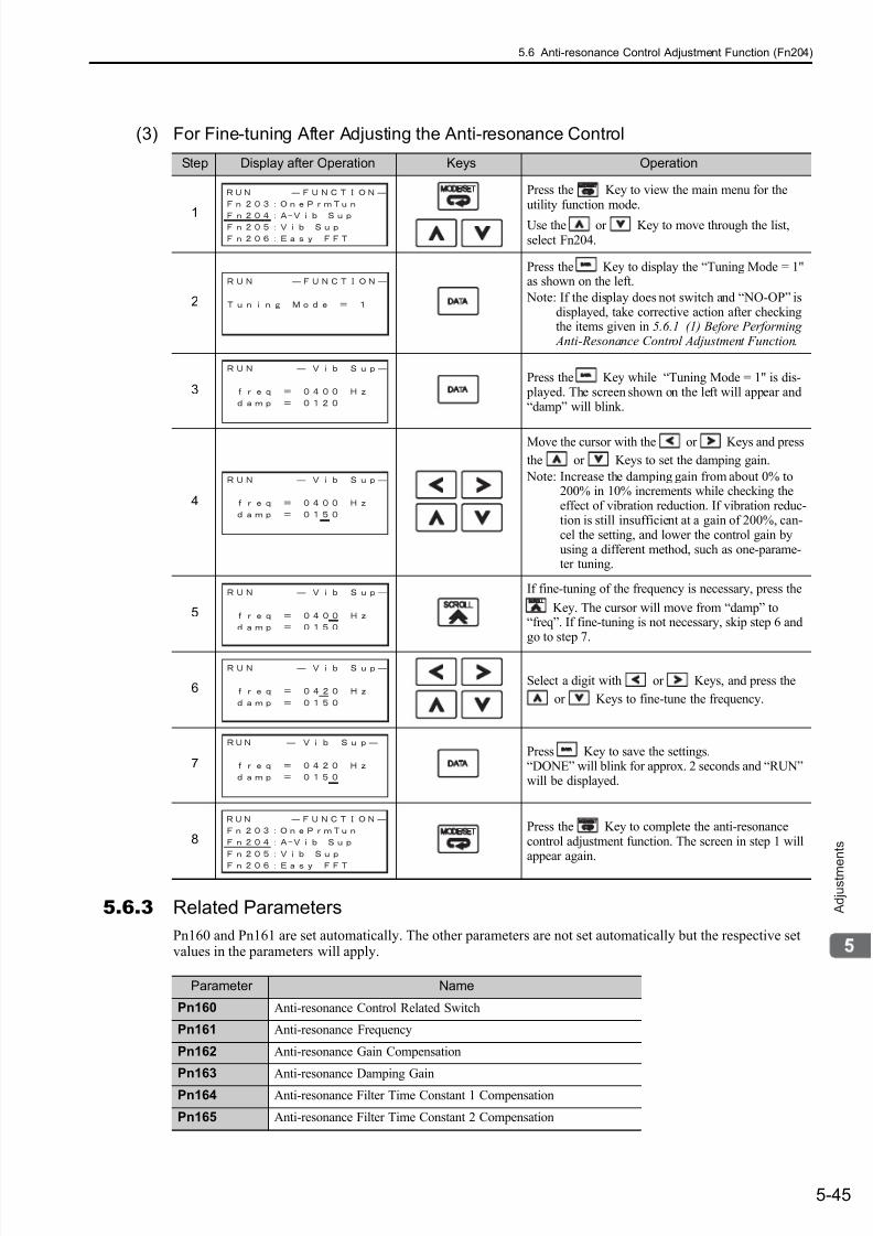
7/17/2019 Manual Yaskawa_servo_drive.pdf
http://slidepdf.com/reader/full/manual-yaskawaservodrivepdf 182/328
5.6 Anti-resonance Control Adjustment Function (Fn204)
5-45
A d j u s t m e
n t s
(3) For Fine-tuning After Adjusting the Anti-resonance Control
5.6.3 Related Parameters
Pn160 and Pn161 are set automatically. The other parameters are not set automatically but the respective setvalues in the parameters will apply.
Step Display after Operation Keys Operation
1
Press the Key to view the main menu for theutility function mode.
Use the or Key to move through the list,select Fn204.
2
Press the Key to display the “Tuning Mode = 1"as shown on the left.
Note: If the display does not switch and “NO-OP” isdisplayed, take corrective action after checkingthe items given in 5.6.1 (1) Before Performing Anti-Resonance Control Adjustment Function.
3Press the Key while “Tuning Mode = 1" is dis- played. The screen shown on the left will appear and“damp” will blink.
4
Move the cursor with the or Keys and press
the or Keys to set the damping gain.
Note: Increase the damping gain from about 0% to200% in 10% increments while checking theeffect of vibration reduction. If vibration reduc-tion is still insufficient at a gain of 200%, can-cel the setting, and lower the control gain byusing a different method, such as one-parame-ter tuning.
5
If fine-tuning of the frequency is necessary, press the
Key. The cursor will move from “damp” to“freq”. If fine-tuning is not necessary, skip step 6 andgo to step 7.
6Select a digit with or Keys, and press the
or Keys to fine-tune the frequency.
7Press Key to save the settings.“DONE” will blink for approx. 2 seconds and “RUN”will be displayed.
8Press the Key to complete the anti-resonancecontrol adjustment function. The screen in step 1 willappear again.
Parameter Name
Pn160 Anti-resonance Control Related Switch
Pn161 Anti-resonance Frequency
Pn162 Anti-resonance Gain Compensation
Pn163 Anti-resonance Damping Gain
Pn164 Anti-resonance Filter Time Constant 1 Compensation
Pn165 Anti-resonance Filter Time Constant 2 Compensation
7/17/2019 Manual Yaskawa_servo_drive.pdf
http://slidepdf.com/reader/full/manual-yaskawaservodrivepdf 183/328
5 Adjustments
5.7.1 Vibration Suppression Function
5-46
5.7 Vibration Suppression Function (Fn205)
This section describes the vibration suppression function.
5.7.1Vibration Suppression FunctionThe vibration suppression function suppresses transitional vibration at frequency as low as 1 to 100 Hz that isgenerated mainly when positioning if the machine stand vibrates.
This function is set automatically when advanced autotuning or advanced autotuning by reference is executed.In most cases, this function is not necessary. Use this function only if fine-tuning is required or readjustment isrequired as a result of a failure to detect vibration.
Perform one-parameter tuning (Fn203) or use another method to increase the responsiveness after performingthis function.
(1) Before Performing Vibration Suppression Function
Check the following settings before performing the vibration suppression function.
a) A message (NO-OP) indicating that no operations are possible will be displayed, if all of the followingconditions are not met.
• The control must be set to position control.
• The tuning-less function must not be enabled.
• Test without motor function must not be enabled. (Pn00C.0 = 0) b) Observe the following condition to ensure operation.
• The write prohibited setting (Fn010) must not be set.
(2) Items Influencing Performance
If continuous vibration occurs when the motor is not rotating, the vibration suppression function cannot beused to suppress the vibration effectively. If the result is not satisfactory, perform anti-resonance controladjustment function (Fn204) or one-parameter tuning (Fn203).
(3) Detection of Vibration Frequencies
No frequency detection may be possible if the vibration does not appear as a position error or the vibrationresulting from the position error is too small.
The detection sensitivity can be adjusted by changing the setting for the remained vibration detection width(Pn560) which is set in accordance with the value of the positioning completed width (Pn522). Perform thedetection of vibration frequencies after adjusting the remained vibration detection width (Pn560).
CAUTION
• If this function is executed, related parameters will be set automatically. Therefore, the response beforeand after using this function may vary greatly. Enable the function in a state where the machine can cometo an emergency stop at any time to ensure the safety operation of the machine.
• Be sure to set a suitable value for the moment of inertia ratio (Pn103) using advanced autotuning beforeexecuting this function. If the setting greatly differs from the actual moment of inertia ratio, normal controlof the SERVOPACK may not be possible, and vibration may result.
• This function detects vibration frequency between 1 to 100 Hz. Vibration will not be
detected for frequencies outside of this range, and instead, “F-----” will be displayed.
• Frequency detection will not be performed if no vibration results from position error or
the vibration frequencies are outside the range of detectable frequencies. If so, use a
device, such as a displacement sensor or vibration sensor, to measure the vibration.• If vibration frequencies automatically detected are not suppressed, the actual fre-
quency and the detected frequency may differ. Fine-tune the detected frequency if
necessary.
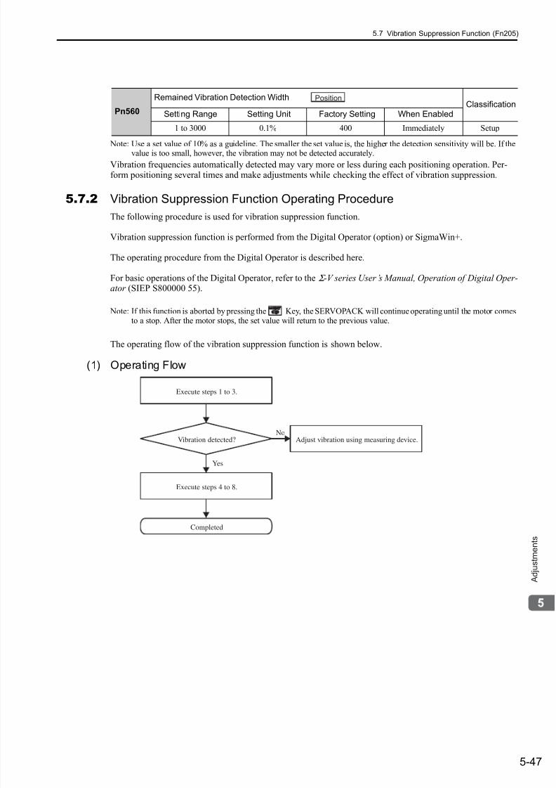
7/17/2019 Manual Yaskawa_servo_drive.pdf
http://slidepdf.com/reader/full/manual-yaskawaservodrivepdf 184/328
5.7 Vibration Suppression Function (Fn205)
5-47
A d j u s t m e
n t s
Note: Use a set value of 10% as a guideline. The smaller the set value is, the higher the detection sensitivity will be. If thevalue is too small, however, the vibration may not be detected accurately.
Vibration frequencies automatically detected may vary more or less during each positioning operation. Per-form positioning several times and make adjustments while checking the effect of vibration suppression.
5.7.2 Vibration Suppression Function Operating Procedure
The following procedure is used for vibration suppression function.
Vibration suppression function is performed from the Digital Operator (option) or SigmaWin+.
The operating procedure from the Digital Operator is described here.
For basic operations of the Digital Operator, refer to the Σ -V series User’s Manual, Operation of Digital Oper-ator (SIEP S800000 55).
Note: If this function is aborted by pressing the Key, the SERVOPACK will continue operating until the motor comesto a stop. After the motor stops, the set value will return to the previous value.
The operating flow of the vibration suppression function is shown below.
(1) Operating Flow
Pn560
Remained Vibration Detection WidthClassification
Setting Range Setting Unit Factory Setting When Enabled
1 to 3000 0.1% 400 Immediately Setup
Position
Vibration detected?
Execute steps 1 to 3.
Completed
Adjust vibration using measuring device.
Execute steps 4 to 8.
Yes
No
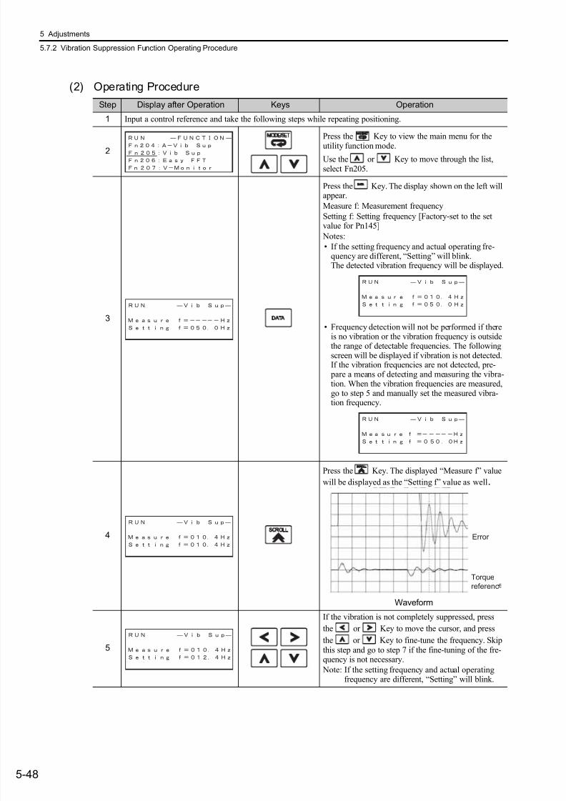
7/17/2019 Manual Yaskawa_servo_drive.pdf
http://slidepdf.com/reader/full/manual-yaskawaservodrivepdf 185/328
5 Adjustments
5.7.2 Vibration Suppression Function Operating Procedure
5-48
(2) Operating Procedure
Step Display after Operation Keys Operation
1 Input a control reference and take the following steps while repeating positioning.
2Press the Key to view the main menu for theutility function mode.
Use the or Key to move through the list,select Fn205.
3
Press the Key. The display shown on the left willappear.
Measure f: Measurement frequency
Setting f: Setting frequency [Factory-set to the setvalue for Pn145]
Notes:
• If the setting frequency and actual operating fre-quency are different, “Setting” will blink.The detected vibration frequency will be displayed.
• Frequency detection will not be performed if thereis no vibration or the vibration frequency is outsidethe range of detectable frequencies. The followingscreen will be displayed if vibration is not detected.If the vibration frequencies are not detected, pre- pare a means of detecting and measuring the vibra-tion. When the vibration frequencies are measured,go to step 5 and manually set the measured vibra-tion frequency.
4
Press the Key. The displayed “Measure f” value
will be displayed as the “Setting f” value as well.
Waveform
5
If the vibration is not completely suppressed, press
the or Key to move the cursor, and press
the or Key to fine-tune the frequency. Skipthis step and go to step 7 if the fine-tuning of the fre-quency is not necessary.
Note: If the setting frequency and actual operatingfrequency are different, “Setting” will blink.
Error
Torque
referenc
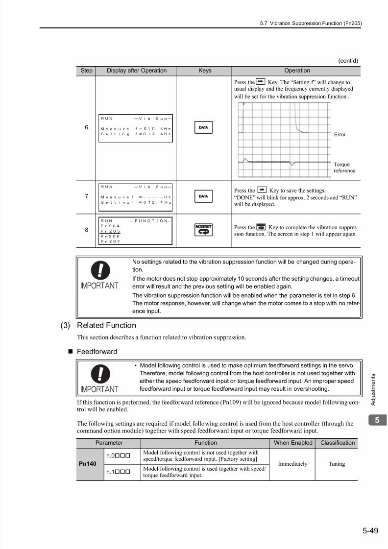
7/17/2019 Manual Yaskawa_servo_drive.pdf
http://slidepdf.com/reader/full/manual-yaskawaservodrivepdf 186/328
5.7 Vibration Suppression Function (Fn205)
5-49
A d j u s t m e
n t s
(3) Related Function
This section describes a function related to vibration suppression.
Feedforward
If this function is performed, the feedforward reference (Pn109) will be ignored because model following con-trol will be enabled.
The following settings are required if model following control is used from the host controller (through thecommand option module) together with speed feedforward input or torque feedforward input.
6
Press the Key. The “Setting f” will change tousual display and the frequency currently displayed
will be set for the vibration suppression function.
7 Press the Key to save the settings.“DONE” will blink for approx. 2 seconds and “RUN”will be displayed.
8 Press the Key to complete the vibration suppres-sion function. The screen in step 1 will appear again.
(cont’d)
Step Display after Operation Keys Operation
Error
Torque
reference
No settings related to the vibration suppression function will be changed during opera-
tion.
If the motor does not stop approximately 10 seconds after the setting changes, a timeout
error will result and the previous setting will be enabled again.The vibration suppression function will be enabled when the parameter is set in step 6.
The motor response, however, will change when the motor comes to a stop with no refer-
ence input.
• Model following control is used to make optimum feedforward settings in the servo.
Therefore, model following control from the host controller is not used together with
either the speed feedforward input or torque feedforward input. An improper speed
feedforward input or torque feedforward input may result in overshooting.
Parameter Function When Enabled Classification
Pn140
n.0Model following control is not used together withspeed/torque feedforward input. [Factory setting]
Immediately Tuning
n.1Model following control is used together with speed/torque feedforward input.

7/17/2019 Manual Yaskawa_servo_drive.pdf
http://slidepdf.com/reader/full/manual-yaskawaservodrivepdf 187/328
5 Adjustments
5.7.3 Related Parameters
5-50
5.7.3 Related Parameters
The following parameters are set automatically by using vibration suppression function. Manual adjustmentsare not required.
Parameter NamePn140 Model Following Control Related Switch
Pn141 Model Following Control Gain
Pn145 Vibration Suppression 1 Frequency A
Pn146 Vibration Suppression 1 Frequency B

7/17/2019 Manual Yaskawa_servo_drive.pdf
http://slidepdf.com/reader/full/manual-yaskawaservodrivepdf 188/328
5.8 Additional Adjustment Function
5-51
A d j u s t m e
n t s
5.8 Additional Adjustment Function
This section describes the functions that can be used for additional fine tuning after making adjustments withadvanced autotuning, advanced autotuning by references, or one-parameter tuning.
• Switching gain settings• Friction compensation
• Current Control Mode Selection
• Current Gain Level Setting
• Speed Detection Method Selection
5.8.1 Switching Gain Settings
Two gain switching functions are available, manual switching and automatic switching. The manual switch-ing function uses an external input signal to switch gains, and the automatic switching function switches gains
automatically.
Note: n.1 is reserved. Do not set.
For the gain combinations for switching, refer to (1) Gain Combinations for Switching .
For the manual gain switching, refer to the manual of the connected command option module.
For the automatic gain switching, refer to (3) Automatic Gain Switching .
(1) Gain Combinations for Switching
∗ The switching gain settings for the model following control gain and the model following control gain compensationare available only for manual gain switching. To enable the gain switching of the these parameters, a gain switchinginput signal must be sent, and the following conditions must be met.
• No command being executed.
• Motor having been completely stopped.
If these conditions are not satisfied, the applicable parameters will not be switched although the other parametersshown in this table will be switched.
(2) Manual Gain Switching
Manual gain switching uses a command (/G-SEL1) from the command option module to switch between gainsetting 1 and gain setting 2.
For details, refer to the manual of the connected command option module.
Parameter Function When Enabled Classification
Pn139n.0 Manual gain switching [Factory setting]
Immediately Tuningn.2 Automatic gain switching
SettingSpeed Loop
Gain
Speed LoopIntegral Time
Constant
Position LoopGain
TorqueReference
Filter
ModelFollowing
Control Gain
ModelFollowing
Control GainCompensation
FrictionCompensation
Gain
GainSetting 1
Pn100Speed LoopGain
Pn101Speed LoopIntegral TimeConstant
Pn102Position LoopGain
Pn4011st step1st TorqueReferenceFilter TimeConstant
Pn141*
Model Follow-ing ControlGain
Pn142*
Model Follow-ing ControlGain Compen-sation
Pn121Friction Com- pensation Gain
Gain
Setting 2
Pn1042nd Speed LoopGain
Pn1052nd Speed Loop
Integral TimeConstant
Pn1062nd PositionLoop Gain
Pn4121st step2nd Torque Ref-erence FilterTime Constant
Pn148*
2nd Model Fol-
lowing ControlGain
Pn149*
2nd Model Fol-lowing ControlGain Compen-sation
Pn1222nd Gain for
FrictionCompensation
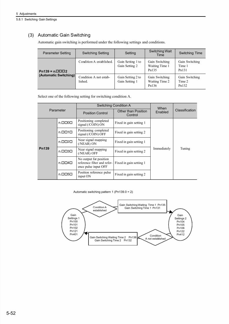
7/17/2019 Manual Yaskawa_servo_drive.pdf
http://slidepdf.com/reader/full/manual-yaskawaservodrivepdf 189/328
5 Adjustments
5.8.1 Switching Gain Settings
5-52
(3) Automatic Gain Switching
Automatic gain switching is performed under the following settings and conditions.
Select one of the following setting for switching condition A.
Parameter Setting Switching Setting SettingSwitching Wait
Time
Switching Time
Pn139 = n.
2(Automatic Switching)
Condition A established. Gain Setting 1 to
Gain Setting 2
Gain Switching
Waiting Time 1
Pn135
Gain Switching
Time 1
Pn131
Condition A not estab-
lished.
Gain Setting 2 to
Gain Setting 1
Gain Switching
Waiting Time 2
Pn136
Gain Switching
Time 2
Pn132
Parameter
Switching Condition AWhen
Enabled
Classification
Position ControlOther than Position
Control
Pn139
n.0Positioning completedsignal (/COIN) ON
Fixed in gain setting 1
Immediately Tuning
n.1Positioning completedsignal (/COIN) OFF
Fixed in gain setting 2
n.2 Near signal mapping(/NEAR) ON
Fixed in gain setting 1
n.3 Near signal mapping(/NEAR) OFF
Fixed in gain setting 2
n.4 No output for positionreference filter and refer-ence pulse input OFF
Fixed in gain setting 1
n.5Position reference pulseinput ON
Fixed in gain setting 2
Gain
Settings 2
Pn104
Pn105
Pn106Pn122
Pn412
Condition Aestablished
Condition A not established
Gain Switching Waiting Time 1 Pn135Gain Switching Time 1 Pn131
Gain Switching Waiting Time 2 Pn136Gain Switching Time 2 Pn132
Gain
Settings 1
Pn100
Pn101
Pn102Pn121
Pn401
Automatic switching pattern 1 (Pn139.0 = 2)
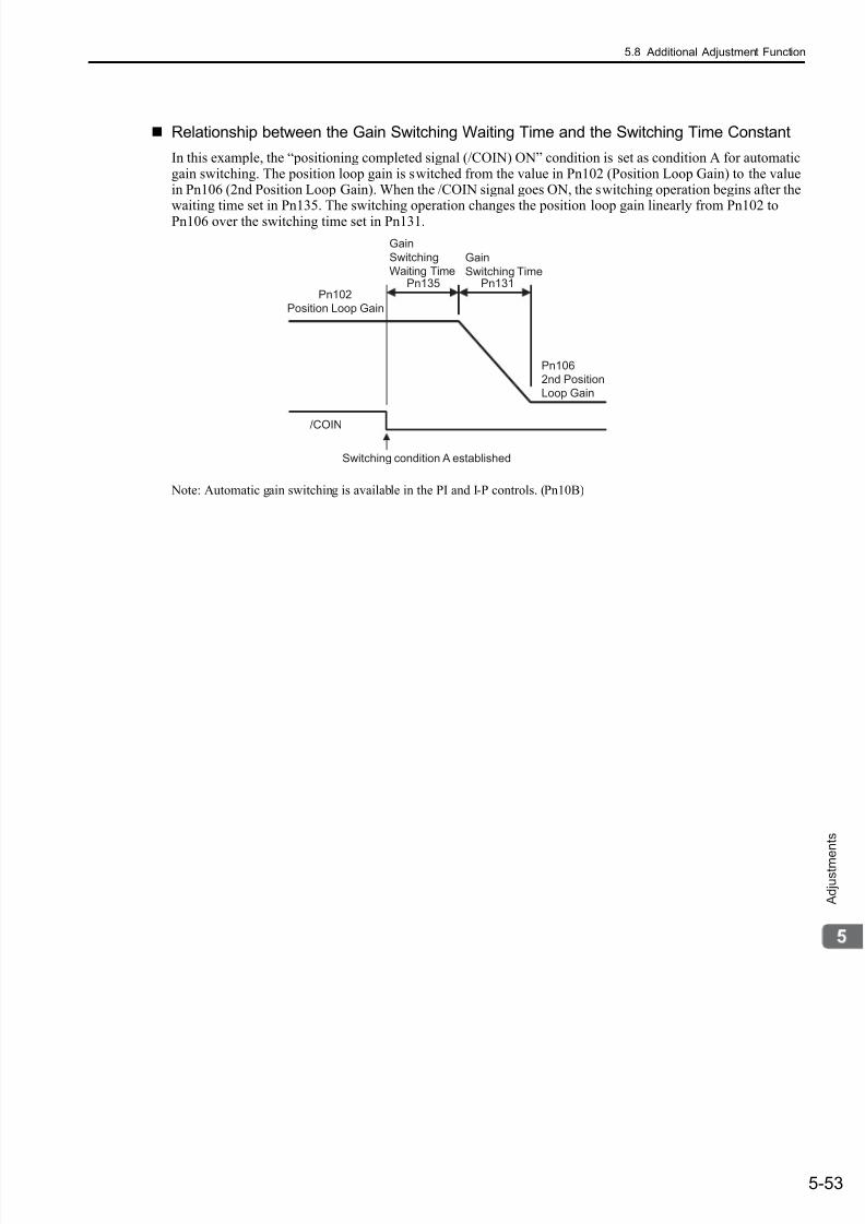
7/17/2019 Manual Yaskawa_servo_drive.pdf
http://slidepdf.com/reader/full/manual-yaskawaservodrivepdf 190/328
5.8 Additional Adjustment Function
5-53
A d j u s t m e
n t s
Relationship between the Gain Switching Waiting Time and the Switching Time Constant
In this example, the “positioning completed signal (/COIN) ON” condition is set as condition A for automaticgain switching. The position loop gain is switched from the value in Pn102 (Position Loop Gain) to the valuein Pn106 (2nd Position Loop Gain). When the /COIN signal goes ON, the switching operation begins after thewaiting time set in Pn135. The switching operation changes the position loop gain linearly from Pn102 toPn106 over the switching time set in Pn131.
Note: Automatic gain switching is available in the PI and I-P controls. (Pn10B)
Switching condition A established
Gain
Switching TimePn131
Gain
Switching
Waiting TimePn135
Pn102
Position Loop Gain
Pn106
2nd Position
Loop Gain
/COIN
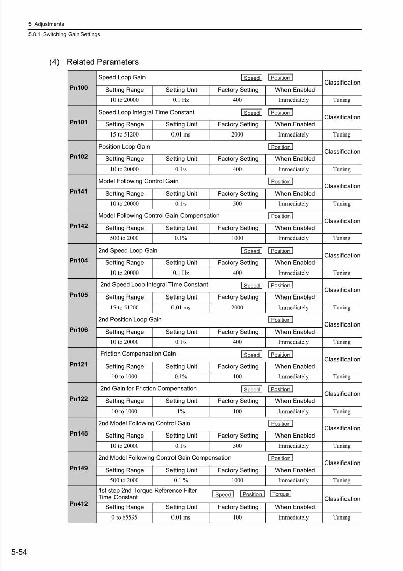
7/17/2019 Manual Yaskawa_servo_drive.pdf
http://slidepdf.com/reader/full/manual-yaskawaservodrivepdf 191/328
5 Adjustments
5.8.1 Switching Gain Settings
5-54
(4) Related Parameters
Pn100
Speed Loop GainClassification
Setting Range Setting Unit Factory Setting When Enabled
10 to 20000 0.1 Hz 400 Immediately Tuning
Pn101
Speed Loop Integral Time ConstantClassification
Setting Range Setting Unit Factory Setting When Enabled
15 to 51200 0.01 ms 2000 Immediately Tuning
Pn102
Position Loop GainClassification
Setting Range Setting Unit Factory Setting When Enabled
10 to 20000 0.1/s 400 Immediately Tuning
Pn141
Model Following Control GainClassification
Setting Range Setting Unit Factory Setting When Enabled
10 to 20000 0.1/s 500 Immediately Tuning
Pn142
Model Following Control Gain CompensationClassification
Setting Range Setting Unit Factory Setting When Enabled
500 to 2000 0.1% 1000 Immediately Tuning
Pn104
2nd Speed Loop GainClassification
Setting Range Setting Unit Factory Setting When Enabled
10 to 20000 0.1 Hz 400 Immediately Tuning
Pn105
2nd Speed Loop Integral Time ConstantClassification
Setting Range Setting Unit Factory Setting When Enabled15 to 51200 0.01 ms 2000 Immediately Tuning
Pn106
2nd Position Loop GainClassification
Setting Range Setting Unit Factory Setting When Enabled
10 to 20000 0.1/s 400 Immediately Tuning
Pn121
Friction Compensation GainClassification
Setting Range Setting Unit Factory Setting When Enabled
10 to 1000 0.1% 100 Immediately Tuning
Pn122
2nd Gain for Friction CompensationClassification
Setting Range Setting Unit Factory Setting When Enabled
10 to 1000 1% 100 Immediately Tuning
Pn148
2nd Model Following Control GainClassification
Setting Range Setting Unit Factory Setting When Enabled
10 to 20000 0.1/s 500 Immediately Tuning
Pn149
2nd Model Following Control Gain CompensationClassification
Setting Range Setting Unit Factory Setting When Enabled
500 to 2000 0.1 % 1000 Immediately Tuning
Pn412
1st step 2nd Torque Reference Filter
Time Constant ClassificationSetting Range Setting Unit Factory Setting When Enabled
0 to 65535 0.01 ms 100 Immediately Tuning
Speed Position
Speed Position
Position
Position
Position
Speed Position
Speed Position
Position
Speed Position
Speed Position
Position
Position
Speed Position Torque

7/17/2019 Manual Yaskawa_servo_drive.pdf
http://slidepdf.com/reader/full/manual-yaskawaservodrivepdf 192/328
5.8 Additional Adjustment Function
5-55
A d j u s t m e
n t s
(5) Parameters for Automatic Gain Switching
(6) Related Monitor
Note: When using the tuning-less function, gain setting 1 is enabled.
Pn131
Gain Switching Time 1Classification
Setting Range Setting Unit Factory Setting When Enabled
0 to 65535 1 ms 0 Immediately Tuning
Pn132
Gain Switching Time 2Classification
Setting Range Setting Unit Factory Setting When Enabled
0 to 65535 1 ms 0 Immediately Tuning
Pn135
Gain Switching Waiting Time 1Classification
Setting Range Setting Unit Factory Setting When Enabled
0 to 65535 1 ms 0 Immediately Tuning
Pn136
Gain Switching Waiting Time 2Classification
Setting Range Setting Unit Factory Setting When Enabled
0 to 65535 1 ms 0 Immediately Tuning
Monitor No. (Un) Name Value Remarks
Un014 Effective gain monitor 1 For gain setting 1
2 For gain setting 2
Position
Position
Position
Position
Parameter Analog Monitor Name Output Value Remarks
Pn006Pn007
n.0B Active gain1 V Gain setting 1 is enabled.
2 V Gain setting 2 is enabled.
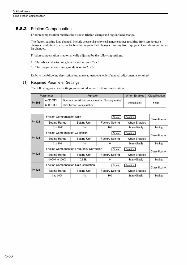
7/17/2019 Manual Yaskawa_servo_drive.pdf
http://slidepdf.com/reader/full/manual-yaskawaservodrivepdf 193/328
5 Adjustments
5.8.2 Friction Compensation
5-56
5.8.2 Friction Compensation
Friction compensation rectifies the viscous friction change and regular load change.
The factors causing load changes include grease viscosity resistance changes resulting from temperature
changes in addition to viscous friction and regular load changes resulting from equipment variations and secu-lar changes.
Friction compensation is automatically adjusted by the following settings.
1. The advanced autotuning level is set to mode 2 or 3.
2. The one-parameter tuning mode is set to 2 or 3.
Refer to the following description and make adjustments only if manual adjustment is required.
(1) Required Parameter Settings
The following parameter settings are required to use friction compensation.
Parameter Function When Enabled Classification
Pn408n.0 Does not use friction compensation. [Factory setting]
Immediately Setupn.1 Uses friction compensation.
Pn121
Friction Compensation GainClassification
Setting Range Setting Unit Factory Setting When Enabled
10 to 1000 1 % 100 Immediately Tuning
Pn123
Friction Compensation CoefficientClassification
Setting Range Setting Unit Factory Setting When Enabled0 to 100 1 % 0 Immediately Tuning
Pn124
Friction Compensation Frequency CorrectionClassification
Setting Range Setting Unit Factory Setting When Enabled
-10000 to 10000 0.1 Hz 0 Immediately Tuning
Pn125
Friction Compensation Gain CorrectionClassification
Setting Range Setting Unit Factory Setting When Enabled
1 to 1000 1 % 100 Immediately Tuning
Speed Position
Speed Position
Speed Position
Speed Position

7/17/2019 Manual Yaskawa_servo_drive.pdf
http://slidepdf.com/reader/full/manual-yaskawaservodrivepdf 194/328
5.8 Additional Adjustment Function
5-57
A d j u s t m e
n t s
(2) Operating Procedure for Friction Compensation
The following procedure is used for friction compensation.
CAUTIONBefore using friction compensation, set the moment of inertia ratio (Pn103) as correctly as possible.
If the wrong moment of inertia ratio is set, vibration may result.
Step Operation
1
Set the following parameters for friction compensation to the factory setting as follows.Friction compensation gain (Pn121): 100Friction compensation coefficient (Pn123): 0Friction compensation frequency correction (Pn124): 0Friction compensation gain correction (Pn125): 100
Note: Always use the factory-set values for friction compensation frequency correction (Pn124) and frictioncompensation gain correction (Pn125).
2To check the effect of friction compensation, increase the friction compensation coefficient (Pn123).
Note: Normally, set the upper limit of the friction compensation coefficient (Pn123) to 95% max.
3
If the friction compensation is insufficient in step 2, increase the set value in Pn121 to where the equipmentdoes not vibrate.
Note: The SERVOPACK may vibrate if Pn121 is set to a value the same as or higher than the resonance fre-quency of the equipment.If necessary, adjust Pn121 in increments of 10%.
Effect of Adjustment
The following graph shows the responsiveness with and without proper adjustment.
Effect of Adjustment Parameters
Pn121: Friction Compensation Gain
This parameter sets the responsiveness for external disturbance. The higher the set value is, the better theresponsiveness will be. If the equipment has a resonance frequency, however, vibration may result if the setvalue is the same as or high than the resonance frequency.
Pn123: Friction Compensation CoefficientThis parameter sets the effect of friction compensation. The higher the set value is, the more effective frictioncompensation will be. If the set value is excessively high, however, the vibration will occur easily. Usually,set the value to 95% or less.
Position error Position error
Small friction
Responsivenessis improved byfriction
compensation.
Large friction
Without friction compensation With friction compensation
Insufficient responsivenessbecause of friction
Reference pulse speedReference pulse speed
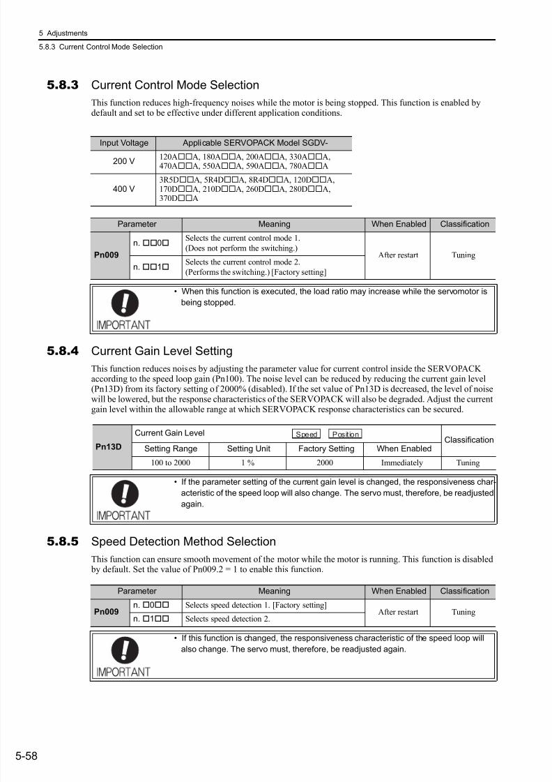
7/17/2019 Manual Yaskawa_servo_drive.pdf
http://slidepdf.com/reader/full/manual-yaskawaservodrivepdf 195/328
5 Adjustments
5.8.3 Current Control Mode Selection
5-58
5.8.3 Current Control Mode Selection
This function reduces high-frequency noises while the motor is being stopped. This function is enabled bydefault and set to be effective under different application conditions.
5.8.4 Current Gain Level Setting
This function reduces noises by adjusting the parameter value for current control inside the SERVOPACKaccording to the speed loop gain (Pn100). The noise level can be reduced by reducing the current gain level(Pn13D) from its factory setting of 2000% (disabled). If the set value of Pn13D is decreased, the level of noisewill be lowered, but the response characteristics of the SERVOPACK will also be degraded. Adjust the current
gain level within the allowable range at which SERVOPACK response characteristics can be secured.
5.8.5 Speed Detection Method Selection
This function can ensure smooth movement of the motor while the motor is running. This function is disabled by default. Set the value of Pn009.2 = 1 to enable this function.
Input Voltage Applicable SERVOPACK Model SGDV-
200 V120AA, 180AA, 200AA, 330AA,470AA, 550AA, 590AA, 780AA
400 V3R5DA, 5R4DA, 8R4DA, 120DA,170DA, 210DA, 260DA, 280DA,370DA
Parameter Meaning When Enabled Classification
Pn009
n. 0Selects the current control mode 1.
(Does not perform the switching.)After restart Tuning
n.1Selects the current control mode 2.
(Performs the switching.) [Factory setting]
• When this function is executed, the load ratio may increase while the servomotor is
being stopped.
Pn13D
Current Gain LevelClassification
Setting Range Setting Unit Factory Setting When Enabled
100 to 2000 1 % 2000 Immediately Tuning
• If the parameter setting of the current gain level is changed, the responsiveness char-
acteristic of the speed loop will also change. The servo must, therefore, be readjusted
again.
Speed Position
Parameter Meaning When Enabled Classification
Pn009n. 0 Selects speed detection 1. [Factory setting]
After restart Tuningn. 1 Selects speed detection 2.
• If this function is changed, the responsiveness characteristic of the speed loop will
also change. The servo must, therefore, be readjusted again.
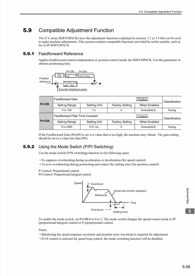
7/17/2019 Manual Yaskawa_servo_drive.pdf
http://slidepdf.com/reader/full/manual-yaskawaservodrivepdf 196/328
5.9 Compatible Adjustment Function
5-59
A d j u s t m e
n t s
5.9 Compatible Adjustment Function
The Σ-V series SERVOPACKs have the adjustment functions explained in sections 5.1 to 5.8 that can be usedto make machine adjustments. This section explains compatible functions provided by earlier models, such asthe Σ-III SERVOPACK.
5.9.1 Feedforward Reference
Applies feedforward control compensation in position control inside the SERVOPACK. Use this parameter toshorten positioning time.
If the Feedforward Gain (Pn109) is set to a value that is too high, the machine may vibrate. The gain settingshould be set to a value less than 80%.
5.9.2 Using the Mode Switch (P/PI Switching)
Use the mode switch (P/PI switching) function in the following cases:
• To suppress overshooting during acceleration or deceleration (for speed control)
• To over overshooting during positioning and reduce the settling time (for position control)
P Control: Proportional controlPI Control: Proportional/integral control
To enable the mode switch, set Pn10B.0 to 0 to 3. The mode switch changes the speed-control mode to PI(proportional/integral) control or P (proportional) control.
Notes:
• Monitoring the speed response waveform and position error waveform is required for adjustment.
• If I-P control is selected for speed loop control, the mode switching function will be disabled.
Pn109
Feedforward GainClassification
Setting Range Setting Unit Factory Setting When Enabled
0 to 100 1% 0 Immediately Tuning
Pn10A
Feedforward Filter Time ConstantClassification
Setting Range Setting Unit Factory Setting When Enabled
0 to 6400 0.01 ms 0 Immediately Tuning
Position
reference
Encoder feedback pulse
+ +
-
Position loopgainKp
Pn109 Pn10ADiffer-ential
Feedforward
Gain
Feedforward Filter
Time Constant
Position
Position
Actual servomotor operation
OvershootSpeed
Reference
Settling timeOvershoot
Time
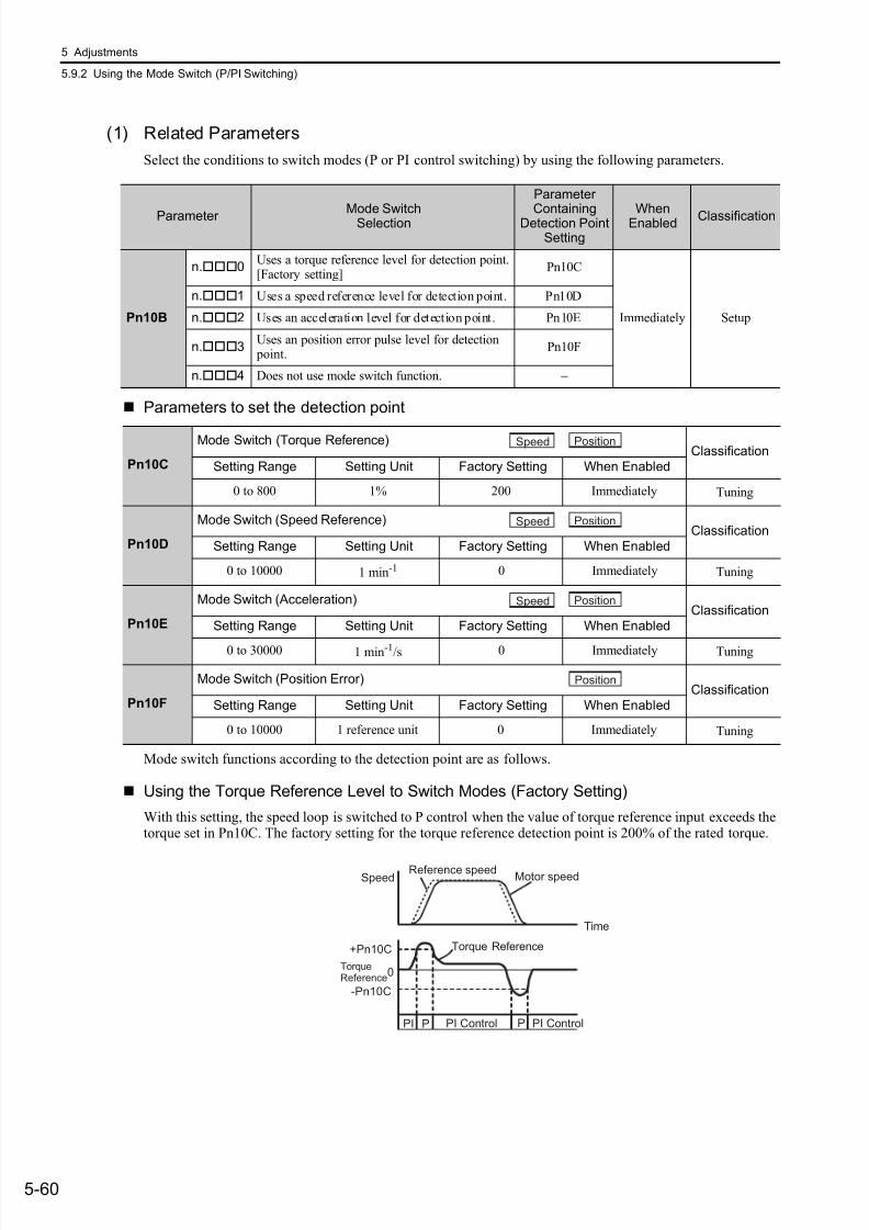
7/17/2019 Manual Yaskawa_servo_drive.pdf
http://slidepdf.com/reader/full/manual-yaskawaservodrivepdf 197/328
5 Adjustments
5.9.2 Using the Mode Switch (P/PI Switching)
5-60
(1) Related Parameters
Select the conditions to switch modes (P or PI control switching) by using the following parameters.
Parameters to set the detection point
Mode switch functions according to the detection point are as follows.
Using the Torque Reference Level to Switch Modes (Factory Setting)
With this setting, the speed loop is switched to P control when the value of torque reference input exceeds thetorque set in Pn10C. The factory setting for the torque reference detection point is 200% of the rated torque.
Parameter Mode SwitchSelection
Parameter
ContainingDetection PointSetting
WhenEnabled Classification
Pn10B
n.0Uses a torque reference level for detection point.[Factory setting]
Pn10C
Immediately Setup
n.1 Uses a speed reference level for detection point. Pn10D
n.2 Uses an acceleration level for detection point. Pn10E
n.3Uses an position error pulse level for detection point.
Pn10F
n.4 Does not use mode switch function. −
Pn10C
Mode Switch (Torque Reference)Classification
Setting Range Setting Unit Factory Setting When Enabled
0 to 800 1% 200 Immediately Tuning
Pn10D
Mode Switch (Speed Reference)Classification
Setting Range Setting Unit Factory Setting When Enabled
0 to 10000 1 min-1 0 Immediately Tuning
Pn10E
Mode Switch (Acceleration)Classification
Setting Range Setting Unit Factory Setting When Enabled
0 to 30000 1 min-1/s 0 Immediately Tuning
Pn10F
Mode Switch (Position Error)Classification
Setting Range Setting Unit Factory Setting When Enabled
0 to 10000 1 reference unit 0 Immediately Tuning
Speed Position
Speed Position
Speed Position
Position
Motor speedReference speed
Speed
+Pn10C
TorqueReference
-Pn10C
Torque Reference
PI Control PI Control
0
PI PP
Time
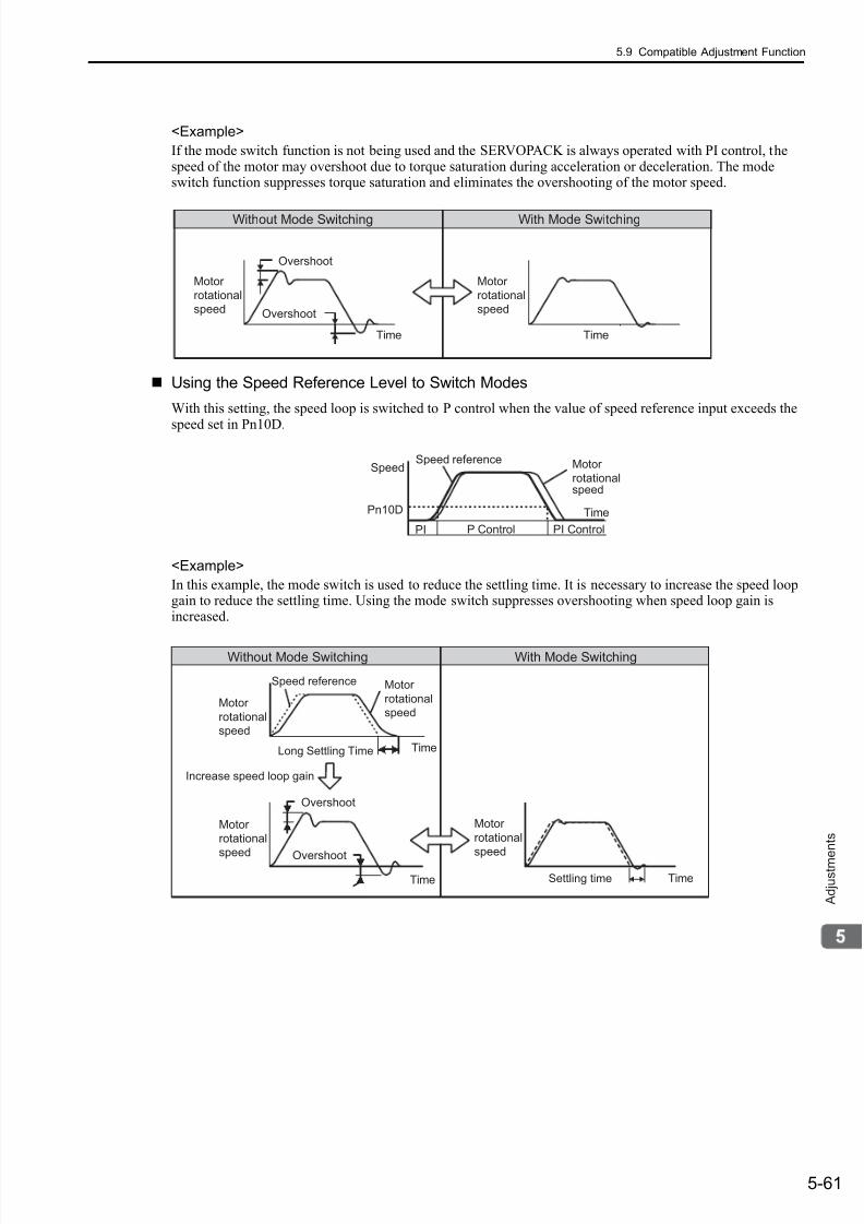
7/17/2019 Manual Yaskawa_servo_drive.pdf
http://slidepdf.com/reader/full/manual-yaskawaservodrivepdf 198/328
5.9 Compatible Adjustment Function
5-61
A d j u s t m e
n t s
<Example>
If the mode switch function is not being used and the SERVOPACK is always operated with PI control, thespeed of the motor may overshoot due to torque saturation during acceleration or deceleration. The modeswitch function suppresses torque saturation and eliminates the overshooting of the motor speed.
Using the Speed Reference Level to Switch Modes
With this setting, the speed loop is switched to P control when the value of speed reference input exceeds the
speed set in Pn10D.
<Example>
In this example, the mode switch is used to reduce the settling time. It is necessary to increase the speed loopgain to reduce the settling time. Using the mode switch suppresses overshooting when speed loop gain isincreased.
Without Mode Switching With Mode Switching
Overshoot
Overshoot
Motor
rotational
speed
Time
Motor
rotational
speed
Time
Speed referenceSpeed Motor
rotational speed
Time
P Control PI Control
Pn10D
PI
Without Mode Switching With Mode Switching
Motor
rotationalspeed
Speed reference
Long Settling Time
Increase speed loop gain
Settling time
Motor
rotationalspeed
Overshoot
Overshoot
Motor
rotational
speed
Time
Motor
rotational
speed
Time
Time
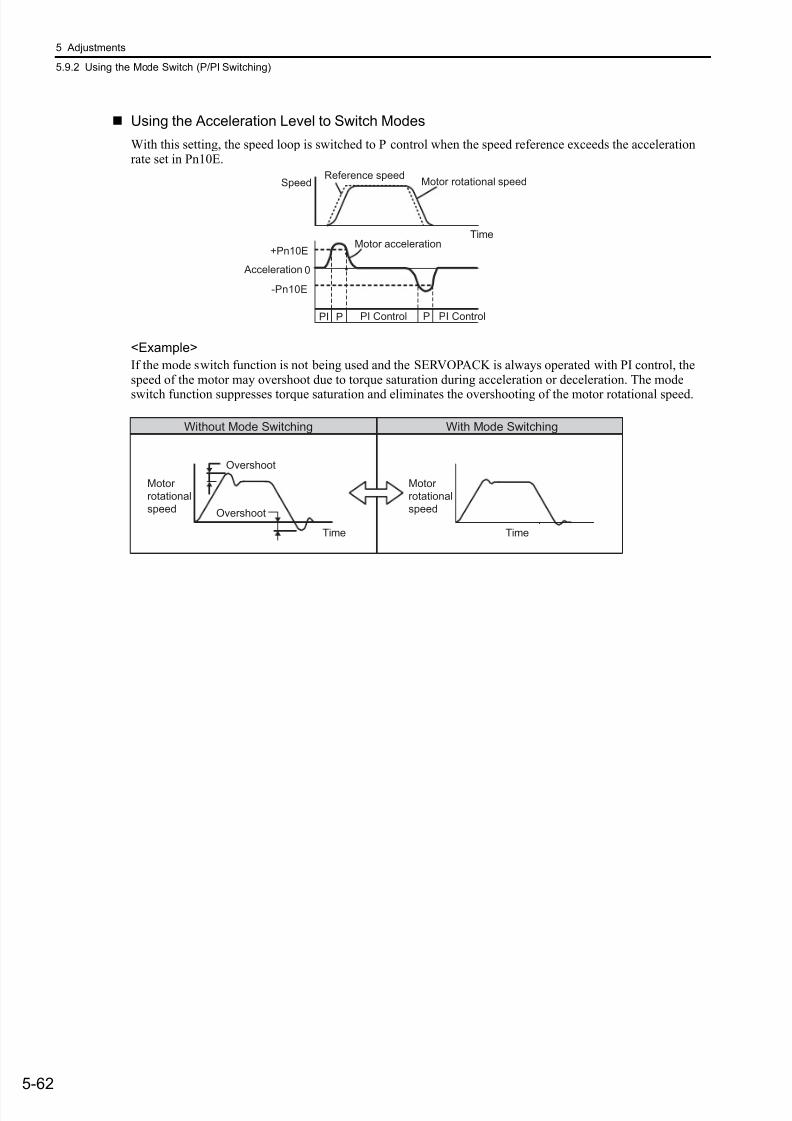
7/17/2019 Manual Yaskawa_servo_drive.pdf
http://slidepdf.com/reader/full/manual-yaskawaservodrivepdf 199/328
5 Adjustments
5.9.2 Using the Mode Switch (P/PI Switching)
5-62
Using the Acceleration Level to Switch Modes
With this setting, the speed loop is switched to P control when the speed reference exceeds the accelerationrate set in Pn10E.
<Example>
If the mode switch function is not being used and the SERVOPACK is always operated with PI control, thespeed of the motor may overshoot due to torque saturation during acceleration or deceleration. The mode
switch function suppresses torque saturation and eliminates the overshooting of the motor rotational speed.
Motor rotational speedReference speed
Speed
Motor acceleration+Pn10E
Acceleration
-Pn10E
PI Control PI Control
0
PI PP
Time
Without Mode Switching With Mode Switching
Overshoot
Overshoot
Motor
rotational
speed
Time
Motor
rotational
speed
Time
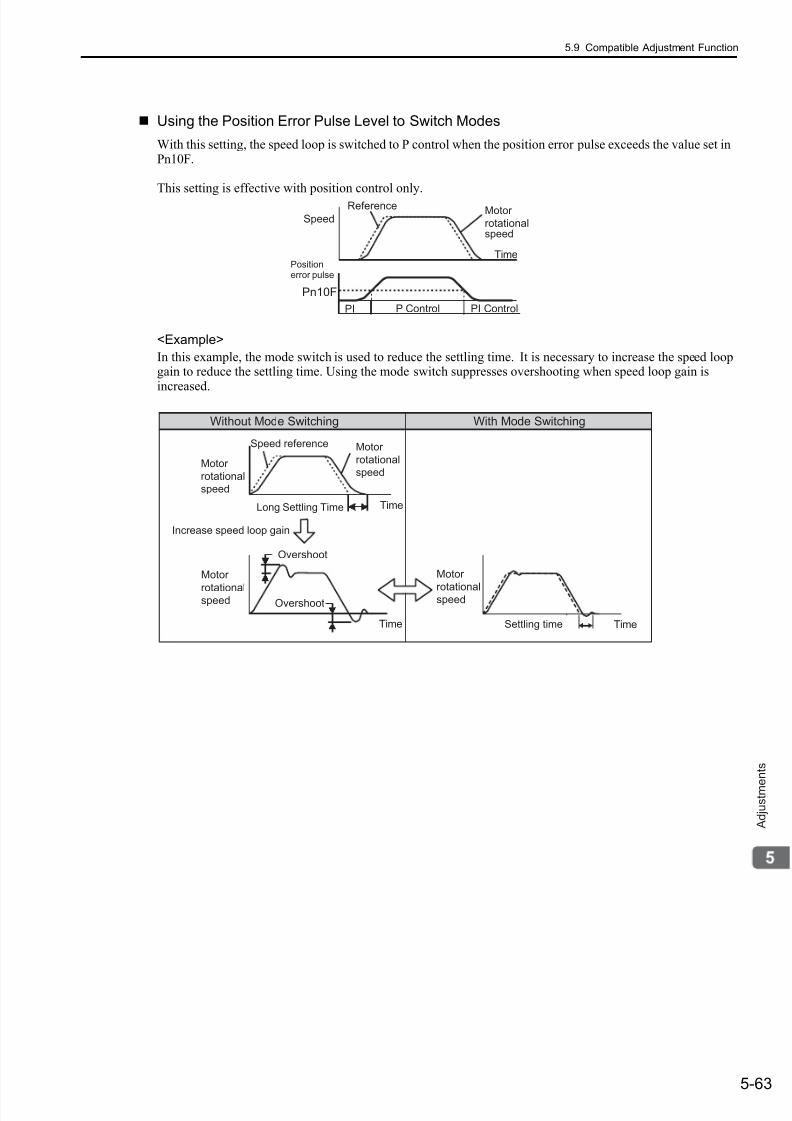
7/17/2019 Manual Yaskawa_servo_drive.pdf
http://slidepdf.com/reader/full/manual-yaskawaservodrivepdf 200/328
5.9 Compatible Adjustment Function
5-63
A d j u s t m e
n t s
Using the Position Error Pulse Level to Switch Modes
With this setting, the speed loop is switched to P control when the position error pulse exceeds the value set inPn10F.
This setting is effective with position control only.
<Example>
In this example, the mode switch is used to reduce the settling time. It is necessary to increase the speed loopgain to reduce the settling time. Using the mode switch suppresses overshooting when speed loop gain is
increased.
Positionerror pulse
Reference
SpeedMotor
rotationalspeed
Time
P Control PI Control
Pn10F
PI
Without Mode Switching With Mode Switching
Motor
rotationalspeed
Speed reference
Long Settling Time
Increase speed loop gain
Settling time
Motor
rotationalspeed
Overshoot
Overshoot
Motor
rotationalspeed
Time
Motor
rotationalspeed
Time
Time

7/17/2019 Manual Yaskawa_servo_drive.pdf
http://slidepdf.com/reader/full/manual-yaskawaservodrivepdf 201/328
5 Adjustments
5.9.3 Torque Reference Filter
5-64
5.9.3 Torque Reference Filter
As shown in the following diagram, the torque reference filter contains first order lag filter and notch filtersarrayed in series, and each filter operates independently. The notch filters can be enabled and disabled with thePn408.
(1) Torque Reference Filter
If you suspect that machine vibration is being caused by the servo drive, try adjusting the filter time constants.This may stop the vibration. The lower the value, the better the speed control response will be, but there is a
lower limit that depends on the machine conditions.
Torque Reference Filter Guide
• Use the speed loop gain (Pn100 [Hz]) and the torque filter time constant (Pn401 [ms]).Adjusted value for stable control: Pn401 [ms] ≤ 1000/ (2π × Pn100 [Hz] × 4)Critical gains: Pn401 [ms] < 1000/ (2π × Pn100 [Hz] × 1)
Torquereferencebeforefiltering
1st step1st TorqueReference
Filter(Pn401)
Torque RelatedFunction SwitchPn408
Notch filter Notch filter First order lag filter
Torquereferenceafterfiltering
Second order lag filter
2nd step2nd TorqueReferenceFilter(Pn40F,Pn410)
2ndNotchFilters(Pn40C,Pn40D and
Pn40E)
1stNotchFilters(Pn409,Pn40A
and Pn40B)
* The 2nd torque reference filter is available when Pn40F is set to a value less than 5000
and not available when Pn40F is set to 5000 (factory setting).
*
Pn401
1st Step 1st Torque Reference Filter
Time Constant Classification
Setting Range Setting Unit Factory Setting When Enabled
0 to 65535 0.01 ms 100 Immediately Tuning
Speed Position Torque
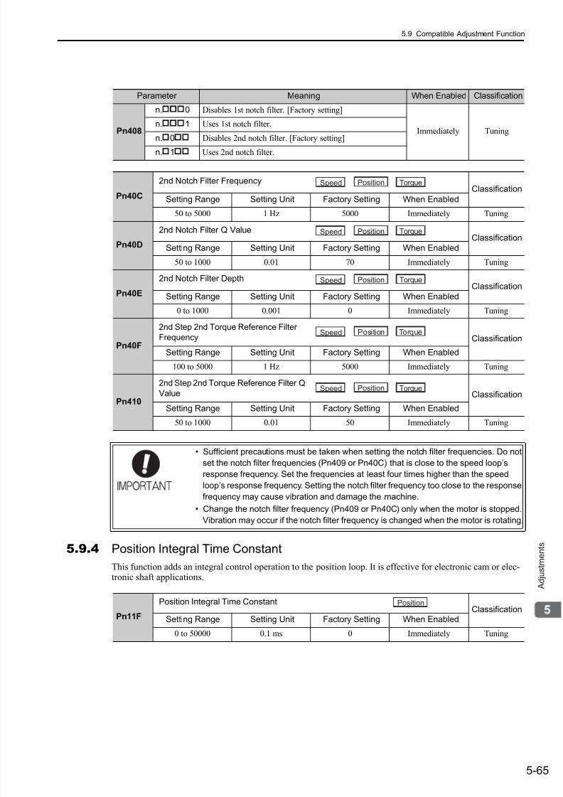
7/17/2019 Manual Yaskawa_servo_drive.pdf
http://slidepdf.com/reader/full/manual-yaskawaservodrivepdf 202/328
5.9 Compatible Adjustment Function
5-65
A d j u s t m e
n t s5.9.4 Position Integral Time Constant
This function adds an integral control operation to the position loop. It is effective for electronic cam or elec-tronic shaft applications.
Parameter Meaning When Enabled Classification
Pn408
n.
0 Disables 1st notch filter. [Factory setting]
Immediately Tuningn.
1 Uses 1st notch filter.
n. 0 Disables 2nd notch filter. [Factory setting]n. 1 Uses 2nd notch filter.
Pn40C
2nd Notch Filter Frequency Classification
Setting Range Setting Unit Factory Setting When Enabled
50 to 5000 1 Hz 5000 Immediately Tuning
Pn40D
2nd Notch Filter Q Value Classification
Setting Range Setting Unit Factory Setting When Enabled
50 to 1000 0.01 70 Immediately Tuning
Pn40E
2nd Notch Filter Depth Classification
Setting Range Setting Unit Factory Setting When Enabled
0 to 1000 0.001 0 Immediately Tuning
Pn40F
2nd Step 2nd Torque Reference Filter
Frequency Classification
Setting Range Setting Unit Factory Setting When Enabled
100 to 5000 1 Hz 5000 Immediately Tuning
Pn410
2nd Step 2nd Torque Reference Filter Q
Value Classification
Setting Range Setting Unit Factory Setting When Enabled
50 to 1000 0.01 50 Immediately Tuning
• Sufficient precautions must be taken when setting the notch filter frequencies. Do not
set the notch filter frequencies (Pn409 or Pn40C) that is close to the speed loop’s
response frequency. Set the frequencies at least four times higher than the speed
loop’s response frequency. Setting the notch filter frequency too close to the response
frequency may cause vibration and damage the machine.
• Change the notch filter frequency (Pn409 or Pn40C) only when the motor is stopped.
Vibration may occur if the notch filter frequency is changed when the motor is rotating.
Speed Position Torque
Speed Position Torque
Speed Position Torque
Speed Position Torque
Speed Position Torque
Pn11F
Position Integral Time ConstantClassification
Setting Range Setting Unit Factory Setting When Enabled
0 to 50000 0.1 ms 0 Immediately Tuning
Position
7/17/2019 Manual Yaskawa_servo_drive.pdf
http://slidepdf.com/reader/full/manual-yaskawaservodrivepdf 203/3286-1
U t i l i t y F u n c t i o n s ( F n )
6
Utility Functions (Fn)
6.1 List of Utility Functions . . . . . . . . . . . . . . . . . . . . . . . . . . . . . . . . . . . . . . .6-2
6.2 Alarm History Display (Fn000) . . . . . . . . . . . . . . . . . . . . . . . . . . . . . . . . .6-3
6.3 JOG Operation (Fn002) . . . . . . . . . . . . . . . . . . . . . . . . . . . . . . . . . . . . . .6-4
6.4 Origin Search (Fn003) . . . . . . . . . . . . . . . . . . . . . . . . . . . . . . . . . . . . . . .6-6
6.5 Program JOG Operation (Fn004) . . . . . . . . . . . . . . . . . . . . . . . . . . . . . . .6-8
6.6 Initializing Parameter Settings (Fn005) . . . . . . . . . . . . . . . . . . . . . . . . . .6-13
6.7 Clearing Alarm History (Fn006) . . . . . . . . . . . . . . . . . . . . . . . . . . . . . . .6-14
6.8 Offset Adjustment of Analog Monitor Output (Fn00C) . . . . . . . . . . . . . .6-15
6.9 Gain Adjustment of Analog Monitor Output (Fn00D) . . . . . . . . . . . . . . .6-17
6.10 Automatic Offset-Signal Adjustment of the Motor Current
Detection (Fn00E) . . . . . . . . . . . . . . . . . . . . . . . . . . . . . . . . . . . . . . . . . 6-19
6.11 Manual Offset-Signal Adjustment of the Motor Current
Detection (Fn00F) . . . . . . . . . . . . . . . . . . . . . . . . . . . . . . . . . . . . . . . . . 6-20
6.12 Write Prohibited Setting (Fn010) . . . . . . . . . . . . . . . . . . . . . . . . . . . . . . 6-21
6.13 Servomotor Model Display (Fn011) . . . . . . . . . . . . . . . . . . . . . . . . . . .6-23
6.14 Software Version Display (Fn012) . . . . . . . . . . . . . . . . . . . . . . . . . . . .6-24
6.15 Resetting Configuration Error of Option Module (Fn014) . . . . . . . . . . .6-25
6.16 Vibration Detection Level Initialization (Fn01B) . . . . . . . . . . . . . . . . . .6-26
6.17 Display of SERVOPACK and Servomotor ID (Fn01E) . . . . . . . . . . . . . 6-28
6.18 Display of Servomotor ID in Feedback Option Module (Fn01F) . . . . . .6-29
6.19 Origin Setting (Fn020) . . . . . . . . . . . . . . . . . . . . . . . . . . . . . . . . . . . . . .6-30
6.20 Software Reset (Fn030) . . . . . . . . . . . . . . . . . . . . . . . . . . . . . . . . . . . . 6-31
6.21 EasyFFT (Fn206) . . . . . . . . . . . . . . . . . . . . . . . . . . . . . . . . . . . . . . . . .6-32
6.22 Online Vibration Monitor (Fn207) . . . . . . . . . . . . . . . . . . . . . . . . . . . . .6-36
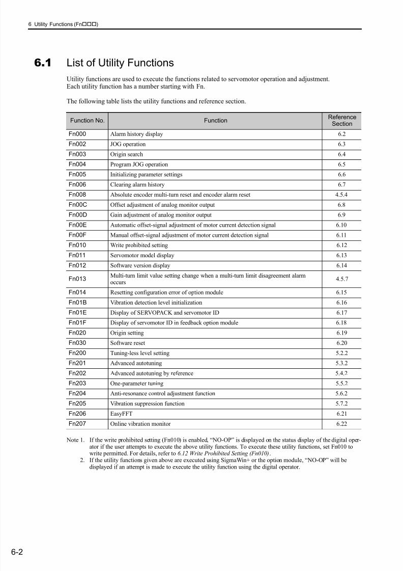
7/17/2019 Manual Yaskawa_servo_drive.pdf
http://slidepdf.com/reader/full/manual-yaskawaservodrivepdf 204/328
6 Utility Functions (Fn)
6-2
6.1 List of Utility Functions
Utility functions are used to execute the functions related to servomotor operation and adjustment.Each utility function has a number starting with Fn.
The following table lists the utility functions and reference section.
Note 1. If the write prohibited setting (Fn010) is enabled, “NO-OP” is displayed on the status display of the digital oper-ator if the user attempts to execute the above utility functions. To execute these utility functions, set Fn010 towrite permitted. For details, refer to 6.12 Write Prohibited Setting (Fn010).
2. If the utility functions given above are executed using SigmaWin+ or the option module, “NO-OP” will bedisplayed if an attempt is made to execute the utility function using the digital operator.
Function No. FunctionReference
Section
Fn000 Alarm history display 6.2
Fn002 JOG operation 6.3
Fn003 Origin search 6.4
Fn004 Program JOG operation 6.5
Fn005 Initializing parameter settings 6.6
Fn006 Clearing alarm history 6.7
Fn008 Absolute encoder multi-turn reset and encoder alarm reset 4.5.4
Fn00C Offset adjustment of analog monitor output 6.8
Fn00D Gain adjustment of analog monitor output 6.9
Fn00E Automatic offset-signal adjustment of motor current detection signal 6.10
Fn00F Manual offset-signal adjustment of motor current detection signal 6.11
Fn010 Write prohibited setting 6.12
Fn011 Servomotor model display 6.13
Fn012 Software version display 6.14
Fn013Multi-turn limit value setting change when a multi-turn limit disagreement alarmoccurs
4.5.7
Fn014 Resetting configuration error of option module 6.15
Fn01B Vibration detection level initialization 6.16
Fn01E Display of SERVOPACK and servomotor ID 6.17
Fn01F Display of servomotor ID in feedback option module 6.18
Fn020 Origin setting 6.19
Fn030 Software reset 6.20
Fn200 Tuning-less level setting 5.2.2
Fn201 Advanced autotuning 5.3.2
Fn202 Advanced autotuning by reference 5.4.2
Fn203 One-parameter tuning 5.5.2
Fn204 Anti-resonance control adjustment function 5.6.2
Fn205 Vibration suppression function 5.7.2
Fn206 EasyFFT 6.21
Fn207 Online vibration monitor 6.22
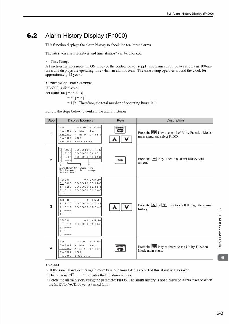
7/17/2019 Manual Yaskawa_servo_drive.pdf
http://slidepdf.com/reader/full/manual-yaskawaservodrivepdf 205/328
6.2 Alarm History Display (Fn000)
6-3
U t i l i t y F u n c t i o n s ( F n )
6.2 Alarm History Display (Fn000)
This function displays the alarm history to check the ten latest alarms.
The latest ten alarm numbers and time stamps* can be checked.
∗ Time Stamps
A function that measures the ON times of the control power supply and main circuit power supply in 100-msunits and displays the operating time when an alarm occurs. The time stamp operates around the clock forapproximately 13 years.
<Example of Time Stamps>
If 36000 is displayed,
3600000 [ms] = 3600 [s]
= 60 [min]
= 1 [h] Therefore, the total number of operating hours is 1.
Follow the steps below to confirm the alarm histories.
<Notes>
• If the same alarm occurs again more than one hour later, a record of this alarm is also saved.
• The message “:_ _ _ ” indicates that no alarm occurs.
• Delete the alarm history using the parameter Fn006. The alarm history is not cleared on alarm reset or when
the SERVOPACK power is turned OFF.
Step Display Example Keys Description
1 Press the Key to open the Utility Function Modemain menu and select Fn000.
2 Press the Key. Then, the alarm history willappear.
3 Press the or Key to scroll through the alarmhistory.
4 Press the Key to return to the Utility FunctionMode main menu.
Alarm History No.
"0" is the latest;"9" is the oldest.
Alarm
No.
Time
stamps

7/17/2019 Manual Yaskawa_servo_drive.pdf
http://slidepdf.com/reader/full/manual-yaskawaservodrivepdf 206/328
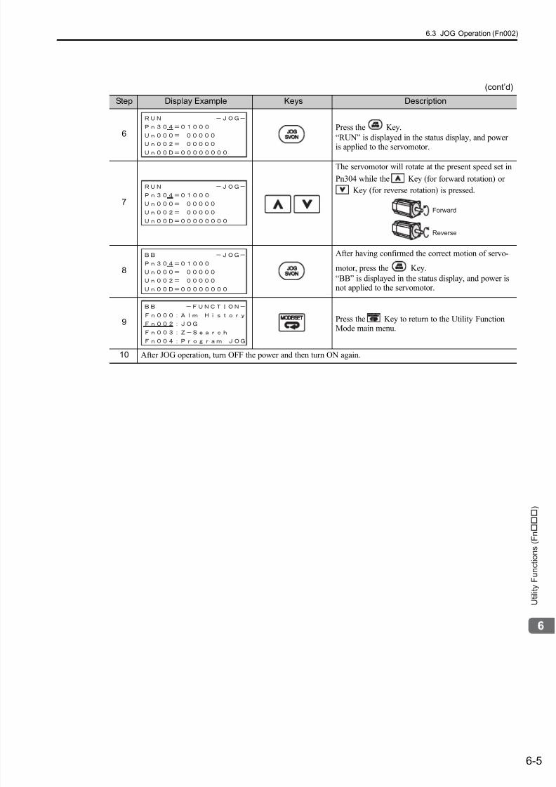
7/17/2019 Manual Yaskawa_servo_drive.pdf
http://slidepdf.com/reader/full/manual-yaskawaservodrivepdf 207/328
6.3 JOG Operation (Fn002)
6-5
U t i l i t y F u n c t i o n s ( F n )
6
Press the Key.
“RUN” is displayed in the status display, and poweris applied to the servomotor.
7
The servomotor will rotate at the present speed set in
Pn304 while the Key (for forward rotation) or
Key (for reverse rotation) is pressed.
8
After having confirmed the correct motion of servo-
motor, press the Key.
“BB” is displayed in the status display, and power isnot applied to the servomotor.
9 Press the Key to return to the Utility FunctionMode main menu.
10 After JOG operation, turn OFF the power and then turn ON again.
(cont’d)
Step Display Example Keys Description
Forward
Reverse

7/17/2019 Manual Yaskawa_servo_drive.pdf
http://slidepdf.com/reader/full/manual-yaskawaservodrivepdf 208/328
6 Utility Functions (Fn)
6-6
6.4 Origin Search (Fn003)
The origin search is designed to position the origin pulse position of the incremental encoder (phase-C) and toclamp at the position.
This mode is used when the motor shaft needs to be aligned to the machine.
Motor speed at the time of execution: 60 min-1
(For SGMCS direct drive motors, the speed at the time of execution is 6 min-1)
(1) Settings before Operation
The following settings are required before performing an origin search.
• If a servo ON command is input, send a servo OFF command.
(2) Operating Procedure
Follow the steps below to execute the origin search.
CAUTION
• Perform origin searches without connecting the coupling.The forward run prohibited (P-OT) and reverse run prohibited (N-OT) signals are not effective in originsearch mode.
For aligning the motor shaft with the machine
Servomotor Machine
Step Display Example Keys Description
1 Press the Key to open the Utility Function Modemain menu and select Fn003.
2
Press the Key. The display is switched to theexecution display of Fn003.
Note:If the display is not switched and “NO-OP” isdisplayed in the status display, change the fol-lowing settings. (Refer to 6.12.)
• If Write Prohibited is set in Fn010:
→ Cancel the Write Prohibited setting.
• If a servo ON command is input:→ Send a servo OFF command.
3
Press the Key.
“RUN” is displayed in the status display, and poweris applied to the servomotor.
Note: If the servomotor is already at the zero position,“-Complete-” is displayed.

7/17/2019 Manual Yaskawa_servo_drive.pdf
http://slidepdf.com/reader/full/manual-yaskawaservodrivepdf 209/328
6.4 Origin Search (Fn003)
6-7
U t i l i t y F u n c t i o n s ( F n )
4
Pressing the Key will rotate the motor in the for-
ward direction. Pressing the Key will rotate the
motor in the reverse direction. The rotation of the ser-vomotor changes according to the setting of Pn000.0.
Note: Direction when viewed from the load of theservomotor.
Press the or Key until the motor stops. Ifthe origin search is completed normally, “-Complete-” is displayed on the right top on the screen.
5
When the origin search is completed, press theKey.
“BB” is displayed in the status display, and powerwill not be applied to the servomotor. The display“-Complete-” changes to “-Z-Search-.”
6 Press the Key to return to the Utility FunctionMode main menu.
7 After origin search operation, turn OFF the power and then turn ON again.
(cont’d)
Step Display Example Keys Description
Parameter key
(Forward)
key
(Reverse)
Pn000n.0 CCW CW
n.1 CW CCW

7/17/2019 Manual Yaskawa_servo_drive.pdf
http://slidepdf.com/reader/full/manual-yaskawaservodrivepdf 210/328
6 Utility Functions (Fn)
6-8
6.5 Program JOG Operation (Fn004)
The Program JOG Operation is a utility function, that allows continuous automatic operation determined bythe preset operation pattern, movement distance, movement speed, acceleration/deceleration time, waitingtime, and number of time of movement.
This function can be used to move the servomotor without it having to be connected to a host controller for themachine as a trial operation in JOG operation mode. Program JOG Operation can be used to confirm the oper-ation and for simple positioning operations.
(1) Settings before Operation
The following settings are required before performing a program JOG operation.
• Consider the machine operation range and safe operation when setting the movement distance and speedcorrectly.
• If a servo ON command has been input, send a servo OFF command.
• The main power is supplied.
• No alarm is detected.
• The overtravel does not occur.• HWBB function is disable.
Note:
• The functions that are applicable for position control, such as position reference filter, can be used.
• The overtravel function is enabled in this function.
(2) Related Parametersf
∗ When using an SGMCS direct drive motor, the setting unit will be automatically changed to 0.1 min-1
Pn530
Program JOG Operation Related SwitchClassification
Setting Range Setting Unit Factory Setting When Enabled
0000 to 0005 − 0000 Immediately Setup
Pn531Program JOG Movement Distance Classification
Setting Range Setting Unit Factory Setting When Enabled
1 to 1073741824 1 reference unit 32768 Immediately Setup
Pn533
Program JOG Movement SpeedClassification
Setting Range Setting Unit Factory Setting When Enabled
1 to 10000 1 min-1* 500 Immediately Setup
Pn534
Program JOG Acceleration/Deceleration TimeClassification
Setting Range Setting Unit Factory Setting When Enabled
2 to 10000 1 ms 100 Immediately Setup
Pn535
Program JOG Waiting TimeClassification
Setting Range Setting Unit Factory Setting When Enabled
0 to 10000 1 ms 100 Immediately Setup
Pn536
Number of Times of Program JOG MovementClassification
Setting Range Setting Unit Factory Setting When Enabled
0 to 1000 1 time 1 Immediately Setup
Speed Position Torque
Speed Position Torque
Speed Position Torque
Speed Position Torque
Speed Position Torque
Speed Position Torque
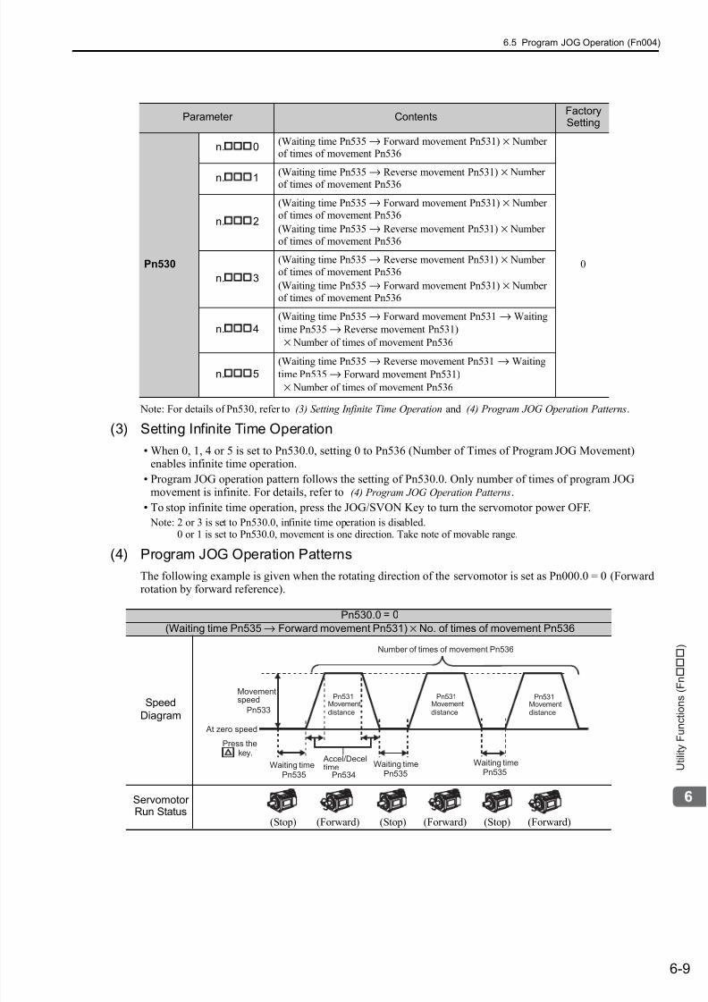
7/17/2019 Manual Yaskawa_servo_drive.pdf
http://slidepdf.com/reader/full/manual-yaskawaservodrivepdf 211/328
6.5 Program JOG Operation (Fn004)
6-9
U t i l i t y F u n c t i o n s ( F n )
Note: For details of Pn530, refer to (3) Setting Infinite Time Operation and (4) Program JOG Operation Patterns.
(3) Setting Infinite Time Operation
• When 0, 1, 4 or 5 is set to Pn530.0, setting 0 to Pn536 (Number of Times of Program JOG Movement)enables infinite time operation.
• Program JOG operation pattern follows the setting of Pn530.0. Only number of times of program JOGmovement is infinite. For details, refer to (4) Program JOG Operation Patterns.
• To stop infinite time operation, press the JOG/SVON Key to turn the servomotor power OFF.
Note: 2 or 3 is set to Pn530.0, infinite time operation is disabled.0 or 1 is set to Pn530.0, movement is one direction. Take note of movable range.
(4) Program JOG Operation Patterns
The following example is given when the rotating direction of the servomotor is set as Pn000.0 = 0 (Forwardrotation by forward reference).
Parameter ContentsFactorySetting
Pn530
n.
0(Waiting time Pn535 → Forward movement Pn531) × Numberof times of movement Pn536
0
n. 1 (Waiting time Pn535 → Reverse movement Pn531) × Numberof times of movement Pn536
n. 2
(Waiting time Pn535 → Forward movement Pn531) × Numberof times of movement Pn536
(Waiting time Pn535 → Reverse movement Pn531) × Number
of times of movement Pn536
n.
3
(Waiting time Pn535 → Reverse movement Pn531) × Number
of times of movement Pn536
(Waiting time Pn535 → Forward movement Pn531) × Numberof times of movement Pn536
n. 4
(Waiting time Pn535 → Forward movement Pn531 → Waiting
time Pn535 → Reverse movement Pn531)
× Number of times of movement Pn536
n.
5
(Waiting time Pn535 → Reverse movement Pn531 → Waiting
time Pn535 → Forward movement Pn531)
× Number of times of movement Pn536
Pn530.0 = 0
(Waiting time Pn535 → Forward movement Pn531) × No. of times of movement Pn536
SpeedDiagram
ServomotorRun Status
(Stop) (Forward) (Stop) (Forward) (Stop) (Forward)
Movement
speedPn533
Waiting timePn535
Accel/Deceltime Waiting time
Pn534 Pn535
Waiting timePn535
Number of times of movement Pn536
At zero speed
Movement
distance
Pn531
Movement
distance
Pn531
Movement
distance
Pn531
key.Press the
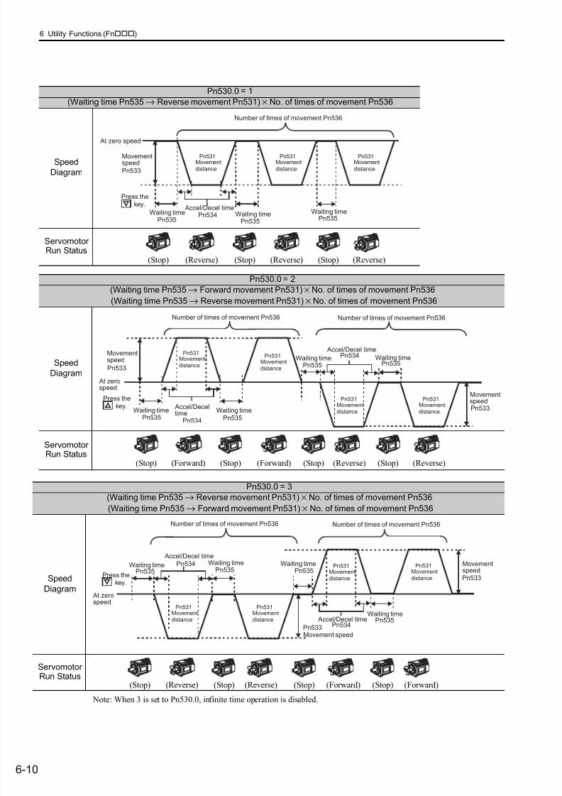
7/17/2019 Manual Yaskawa_servo_drive.pdf
http://slidepdf.com/reader/full/manual-yaskawaservodrivepdf 212/328
6 Utility Functions (Fn)
6-10
Note: When 3 is set to Pn530.0, infinite time operation is disabled.
Pn530.0 = 1
(Waiting time Pn535 → Reverse movement Pn531) × No. of times of movement Pn536
Speed
Diagram
ServomotorRun Status
(Stop) (Reverse) (Stop) (Reverse) (Stop) (Reverse)
Movementspeed
Pn533
Waiting timePn535
Accel/Decel timeWaiting timePn534
Pn535
Waiting timePn535
Number of times of movement Pn536
At zero speed
Movement
distance
Pn531
Movement
distance
Pn531
Movement
distance
Pn531
key.Press the
Pn530.0 = 2(Waiting time Pn535 → Forward movement Pn531) × No. of times of movement Pn536
(Waiting time Pn535 → Reverse movement Pn531) × No. of times of movement Pn536
Speed
Diagram
ServomotorRun Status
(Stop) (Forward) (Stop) (Forward) (Stop) (Reverse) (Stop) (Reverse)
Movementspeed Movement
distancePn533
Pn531
Waiting time
Pn535
Accel/Deceltime
Accel/Decel time
Waiting time
Pn534 Pn535
Waiting time Waiting timePn535
MovementspeedPn533
Pn534
Pn535
Number of times of movement Pn536 Number of times of movement Pn536
At zerospeed
Movementdistance
Pn531
Movementdistance
Pn531Movementdistance
Pn531
key.Press the
Pn530.0 = 3
(Waiting time Pn535 → Reverse movement Pn531) × No. of times of movement Pn536
(Waiting time Pn535 → Forward movement Pn531) × No. of times of movement Pn536
Speed
Diagram
ServomotorRun Status
(Stop) (Reverse) (Stop) (Reverse) (Stop) (Forward) (Stop) (Forward)
Movement speedPn533
Accel/Decel time
Accel/Decel time
Pn534 Waiting time
Waiting timePn535
MovementspeedPn533
Pn534
Pn535Waiting time
Pn535
Waiting timePn535
Number of times of movement Pn536 Number of times of movement Pn536
At zerospeed
Movementdistance
Pn531Movementdistance
Pn531
Movementdistance
Pn531Movementdistance
Pn531
key.Press the
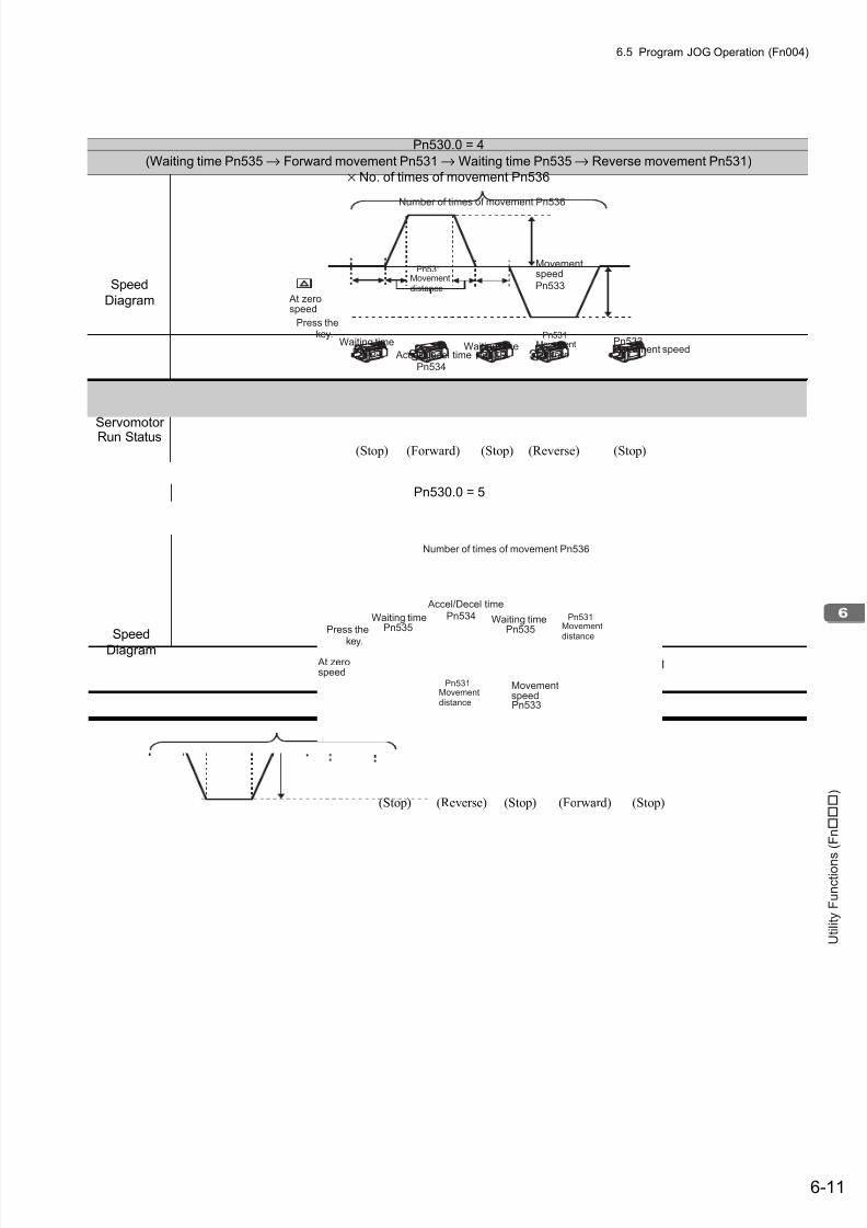
7/17/2019 Manual Yaskawa_servo_drive.pdf
http://slidepdf.com/reader/full/manual-yaskawaservodrivepdf 213/328
6.5 Program JOG Operation (Fn004)
6-11
U t i l i t y F u n c t i o n s ( F n )
Pn530.0 = 4
(Waiting time Pn535 → Forward movement Pn531 → Waiting time Pn535 → Reverse movement Pn531)
× No. of times of movement Pn536
Speed
Diagram
ServomotorRun Status
Movement speedPn533
Accel/Decel timePn534
Pn533
Waiting timePn535
Waiting timePn535
Number of times of movement Pn536
Movementspeed
At zerospeed
Movement
distance
Pn531
Movement
distance
Pn531 key.Press the
(Stop) (Stop) (Stop)(Reverse)(Forward)
Pn530.0 = 5
(Waiting time Pn535 → Reverse movement Pn531 → Waiting time Pn535 → Forward movement Pn531)
× No. of times of movement Pn536
Speed
Diagram
ServomotorRun Status
MovementspeedPn533
Accel/Decel timePn534Waiting time
Pn535Waiting time
Pn535
Number of times of movement Pn536
At zerospeed
Movementdistance
Pn531
Movementdistance
Pn531
key.
Press the
(Stop) (Stop) (Stop)(Reverse) (Forward)
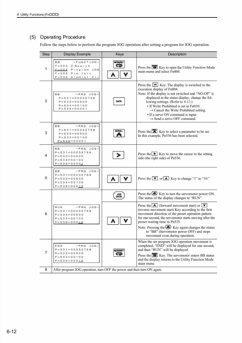
7/17/2019 Manual Yaskawa_servo_drive.pdf
http://slidepdf.com/reader/full/manual-yaskawaservodrivepdf 214/328
6 Utility Functions (Fn)
6-12
(5) Operating Procedure
Follow the steps below to perform the program JOG operation after setting a program for JOG operation.
Step Display Example Keys Description
1 Press the Key to open the Utility Function Modemain menu and select Fn004.
2
Press the Key. The display is switched to theexecution display of Fn004.
Note: If the display is not switched and “NO-OP” isdisplayed in the status display, change the fol-lowing settings. (Refer to 6.12.)
• If Write Prohibited is set in Fn010:→ Cancel the Write Prohibited setting.
• If a servo ON command is input:
→ Send a servo OFF command.
3 Press the Key to select a parameter to be set.In this example, Pn536 has been selected.
4 Press the Key to move the cursor to the settingside (the right side) of Pn536.
5Press the or Key to change “1” to “10.”
6
Press the Key to turn the servomotor power ON.The status of the display changes to “RUN”.
Press the (forward movement start) or(reverse movement start) Key according to the firstmovement direction of the preset operation patternfor one second, the servomotor starts moving after the preset waiting time in Pn535.
Note: Pressing the Key again changes the statusto “BB” (Servomotor power OFF) and stopsmovement even during operation.
7
When the set program JOG operation movement iscompleted, “END” will be displayed for one second,and then “RUN” will be displayed.
Press the Key. The servomotor enters BB statusand the display returns to the Utility Function Modemain menu.
8 After program JOG operation, turn OFF the power and then turn ON again.
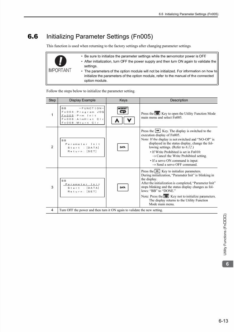
7/17/2019 Manual Yaskawa_servo_drive.pdf
http://slidepdf.com/reader/full/manual-yaskawaservodrivepdf 215/328
6.6 Initializing Parameter Settings (Fn005)
6-13
U t i l i t y F u n c t i o n s ( F n )
6.6 Initializing Parameter Settings (Fn005)
This function is used when returning to the factory settings after changing parameter settings.
Follow the steps below to initialize the parameter setting.
• Be sure to initialize the parameter settings while the servomotor power is OFF.• After initialization, turn OFF the power supply and then turn ON again to validate the
settings.
• The parameters of the option module will not be initialized. For information on how to
initialize the parameters of the option module, refer to the manual of the connected
option module.
Step Display Example Keys Description
1
Press the Key to open the Utility Function Mode
main menu and select Fn005.
2
Press the Key. The display is switched to the
execution display of Fn005.
Note: If the display is not switched and “NO-OP” isdisplayed in the status display, change the fol-lowing settings. (Refer to 6.12.)
• If Write Prohibited is set in Fn010:→ Cancel the Write Prohibited setting.
• If a servo ON command is input:→ Send a servo OFF command.
3
Press the Key to initialize parameters.
During initialization, “Parameter Init” is blinking inthe display.After the initialization is completed, “Parameter Init”stops blinking and the status display changes as fol-lows: “BB” to “DONE.”
Note: Press the Key not to initialize parameters.The display returns to the Utility FunctionMode main menu.
4 Turn OFF the power and then turn it ON again to validate the new setting.
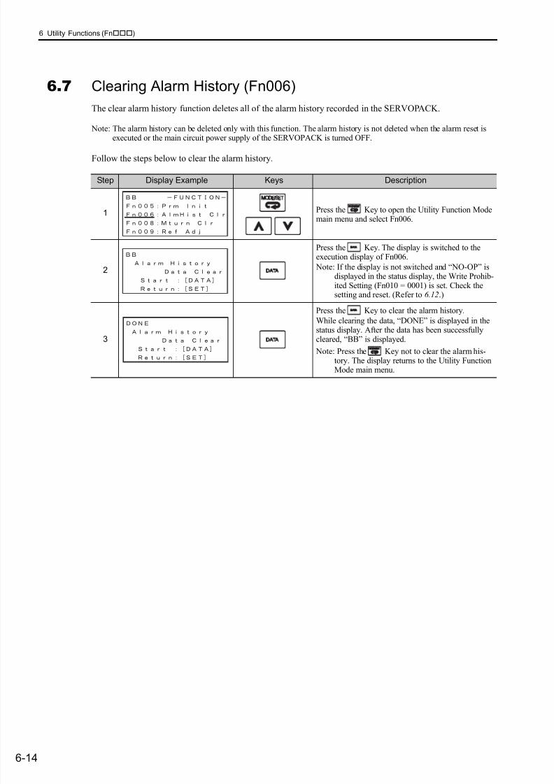
7/17/2019 Manual Yaskawa_servo_drive.pdf
http://slidepdf.com/reader/full/manual-yaskawaservodrivepdf 216/328
6 Utility Functions (Fn)
6-14
6.7 Clearing Alarm History (Fn006)
The clear alarm history function deletes all of the alarm history recorded in the SERVOPACK.
Note: The alarm history can be deleted only with this function. The alarm history is not deleted when the alarm reset is
executed or the main circuit power supply of the SERVOPACK is turned OFF.
Follow the steps below to clear the alarm history.
Step Display Example Keys Description
1 Press the Key to open the Utility Function Modemain menu and select Fn006.
2
Press the Key. The display is switched to theexecution display of Fn006.
Note: If the display is not switched and “NO-OP” is
displayed in the status display, the Write Prohib-ited Setting (Fn010 = 0001) is set. Check thesetting and reset. (Refer to 6.12.)
3
Press the Key to clear the alarm history.
While clearing the data, “DONE” is displayed in thestatus display. After the data has been successfullycleared, “BB” is displayed.
Note: Press the Key not to clear the alarm his-tory. The display returns to the Utility FunctionMode main menu.
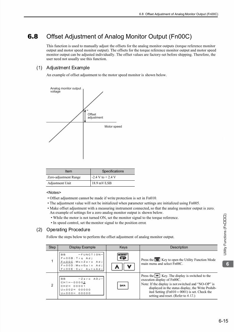
7/17/2019 Manual Yaskawa_servo_drive.pdf
http://slidepdf.com/reader/full/manual-yaskawaservodrivepdf 217/328
6.8 Offset Adjustment of Analog Monitor Output (Fn00C)
6-15
U t i l i t y F u n c t i o n s ( F n )
6.8 Offset Adjustment of Analog Monitor Output (Fn00C)
This function is used to manually adjust the offsets for the analog monitor outputs (torque reference monitoroutput and motor speed monitor output). The offsets for the torque reference monitor output and motor speedmonitor output can be adjusted individually. The offset values are factory-set before shipping. Therefore, the
user need not usually use this function.
(1) Adjustment Example
An example of offset adjustment to the motor speed monitor is shown below.
<Notes>
• Offset adjustment cannot be made if write protection is set in Fn010.
• The adjustment value will not be initialized when parameter settings are initialized using Fn005.
• Make offset adjustment with a measuring instrument connected, so that the analog monitor output is zero.An example of settings for a zero analog monitor output is shown below.
• While the motor is not turned ON, set the monitor signal to the torque reference.
• In speed control, set the monitor signal to the position error.
(2) Operating Procedure
Follow the steps below to perform the offset adjustment of analog monitor output.
Item Specifications
Zero-adjustment Range -2.4 V to + 2.4 V
Adjustment Unit 18.9 mV/LSB
Analog monitor outputvoltage
Motor speed
Offsetadjustment
Step Display Example Keys Description
1 Press the Key to open the Utility Function Modemain menu and select Fn00C.
2
Press the Key. The display is switched to theexecution display of Fn00C.
Note: If the display is not switched and “NO-OP” isdisplayed in the status display, the Write Prohib-
ited Setting (Fn010 = 0001) is set. Check thesetting and reset. (Refer to 6.12.)
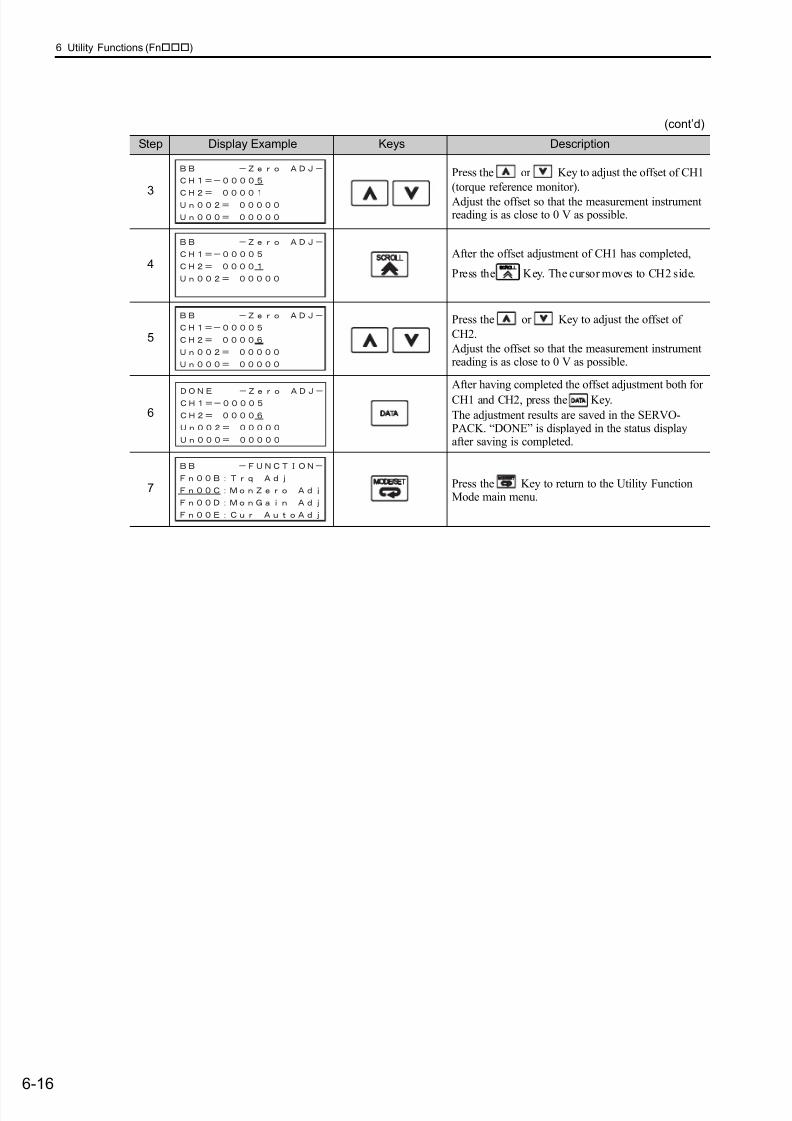
7/17/2019 Manual Yaskawa_servo_drive.pdf
http://slidepdf.com/reader/full/manual-yaskawaservodrivepdf 218/328
6 Utility Functions (Fn)
6-16
3
Press the or Key to adjust the offset of CH1
(torque reference monitor).
Adjust the offset so that the measurement instrumentreading is as close to 0 V as possible.
4After the offset adjustment of CH1 has completed,
Press the Key. The cursor moves to CH2 side.
5
Press the or Key to adjust the offset of
CH2.
Adjust the offset so that the measurement instrumentreading is as close to 0 V as possible.
6
After having completed the offset adjustment both for
CH1 and CH2, press the Key.
The adjustment results are saved in the SERVO-PACK. “DONE” is displayed in the status displayafter saving is completed.
7 Press the Key to return to the Utility FunctionMode main menu.
(cont’d)
Step Display Example Keys Description

7/17/2019 Manual Yaskawa_servo_drive.pdf
http://slidepdf.com/reader/full/manual-yaskawaservodrivepdf 219/328
6.9 Gain Adjustment of Analog Monitor Output (Fn00D)
6-17
U t i l i t y F u n c t i o n s ( F n )
6.9 Gain Adjustment of Analog Monitor Output (Fn00D)
This function is used to manually adjust the gains for the analog monitor outputs (torque reference monitoroutput and motor speed monitor output). The gains for the torque reference monitor output and motor speedmonitor output can be adjusted individually. The gain values are factory-set before shipping. Therefore, the
user need not usually use this function.
(1) Adjustment Example
An example of gains adjustment to the motor speed monitor is shown below.
The gain adjustment width is made with a 100% output set as a center value (adjustment range: 50% to 150%).A setting example is shown below.
<Setting the Set Value to −125>
100% + (−125 × 0.4) = 50%
Therefore, the monitor output voltage is 0.5 times as high.
<Setting the Set Value to 125>
100% + (125 × 0.4) =150%Therefore, the monitor output voltage is 1.5 times as high.
<Notes>
• Gain adjustment cannot be made if write protection is set in Fn010.
• The adjustment value will not be initialized when parameter settings are initialized using Fn005.
Item Specifications
Gain-adjustment Range 50% to 150%
Adjustment Unit 0.4%/LSB
Analog monitor
output voltage
Gain adjustment
Motor speed
1
[V]
[1000 min-1]
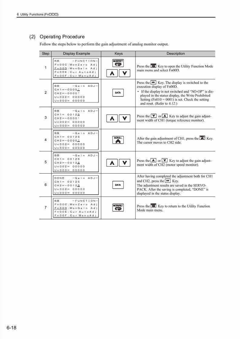
7/17/2019 Manual Yaskawa_servo_drive.pdf
http://slidepdf.com/reader/full/manual-yaskawaservodrivepdf 220/328
6 Utility Functions (Fn)
6-18
(2) Operating Procedure
Follow the steps below to perform the gain adjustment of analog monitor output.
Step Display Example Keys Description
1 Press the Key to open the Utility Function Modemain menu and select Fn00D.
2
Press the Key. The display is switched to theexecution display of Fn00D.
• If the display is not switched and “NO-OP” is dis- played in the status display, the Write ProhibitedSetting (Fn010 = 0001) is set. Check the settingand reset. (Refer to 6.12.)
3Press the or Key to adjust the gain adjust-ment width of CH1 (torque reference monitor).
4 After the gain adjustment of CH1, press the Key.The cursor moves to CH2 side.
5 Press the or Key to adjust the gain adjust-ment width of CH2 (motor speed monitor).
6
After having completed the adjustment both for CH1
and CH2, press the Key.
The adjustment results are saved in the SERVO-PACK. After the saving is completed, “DONE” isdisplayed in the status display.
7 Press the Key to return to the Utility FunctionMode main menu.
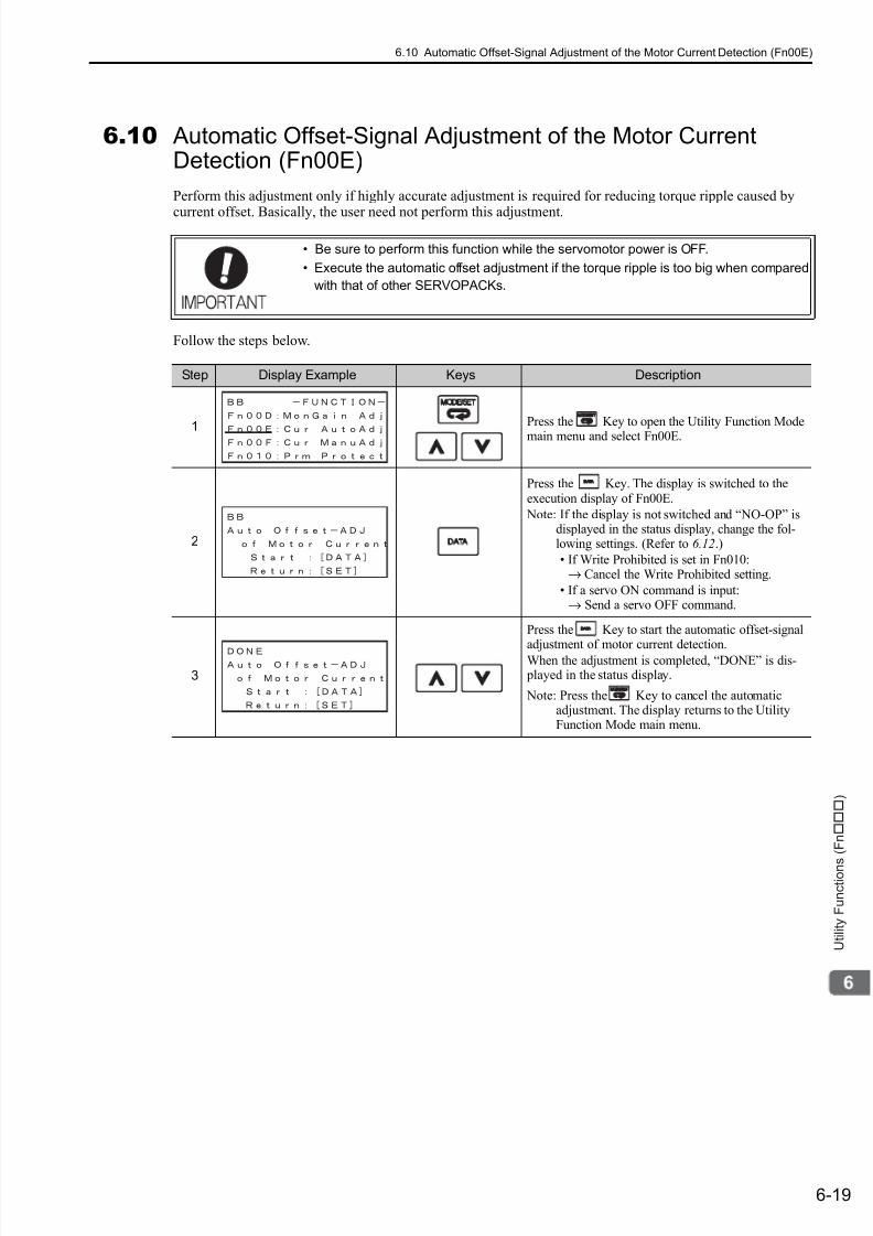
7/17/2019 Manual Yaskawa_servo_drive.pdf
http://slidepdf.com/reader/full/manual-yaskawaservodrivepdf 221/328
6.10 Automatic Offset-Signal Adjustment of the Motor Current Detection (Fn00E)
6-19
U t i l i t y F u n c t i o n s ( F n )
6.10 Automatic Offset-Signal Adjustment of the Motor CurrentDetection (Fn00E)
Perform this adjustment only if highly accurate adjustment is required for reducing torque ripple caused by
current offset. Basically, the user need not perform this adjustment.
Follow the steps below.
• Be sure to perform this function while the servomotor power is OFF.
• Execute the automatic offset adjustment if the torque ripple is too big when compared
with that of other SERVOPACKs.
Step Display Example Keys Description
1
Press the Key to open the Utility Function Mode
main menu and select Fn00E.
2
Press the Key. The display is switched to theexecution display of Fn00E.
Note: If the display is not switched and “NO-OP” isdisplayed in the status display, change the fol-lowing settings. (Refer to 6.12.)
• If Write Prohibited is set in Fn010:→ Cancel the Write Prohibited setting.
• If a servo ON command is input:→ Send a servo OFF command.
3
Press the Key to start the automatic offset-signal
adjustment of motor current detection.When the adjustment is completed, “DONE” is dis- played in the status display.
Note: Press the Key to cancel the automaticadjustment. The display returns to the UtilityFunction Mode main menu.

7/17/2019 Manual Yaskawa_servo_drive.pdf
http://slidepdf.com/reader/full/manual-yaskawaservodrivepdf 222/328
6 Utility Functions (Fn)
6-20
6.11 Manual Offset-Signal Adjustment of the Motor CurrentDetection (Fn00F)
Use this function only if the torque ripple is still high after the automatic offset adjustment of the motor cur-
rent detection signal (Fn00E).
Follow the steps below.
If this function is executed carelessly, it may worsen the characteristics.
Observe the following precautions when performing manual servo tuning.
• Run the servomotor at a speed of approximately 100 min-1.
• Adjust the offset until the torque reference monitor ripple is minimized, monitoring the
torque reference by using the analog monitor.
• Adjust the phase-U and phase-V offsets alternately several times until these offsets
are well balanced.
Step Display Example Keys Description
1 Press the Key to open the Utility Function Modemain menu and select Fn00F.
2
Press the Key. The display is switched to theexecution display of Fn00F.
Note: If the display is not switched and “NO-OP” isdisplayed in the status display, the Write Prohib-ited Setting (Fn010 = 0001) is set. Check thesetting and reset. (Refer to 6.12.)
3
Press the or Key to adjust the offset amountof phase-U.
Adjust the offset amount by 10 in the direction thatthe torque ripple is reduced.
Adjustment range: -512 to +511
4 Press the Key. The cursor moves to the phase-Vside.
5
Press the or Key to adjust the offset amountof phase-V.
Adjust the offset amount by 10 in the direction that
the torque ripple is reduced.Adjustment range: -512 to +511
6Repeat the above operations (phase-U and-V alternately) until adjusting the offset amounts both for phase-U and-V in both directions cannot reduce the torque ripple any more.Then, perform the same operation by adjusting by smaller amount.
7
Press the Key to save the result of adjustment inthe SERVOPACK.
When the saving is completed, “DONE” is displayedin the status display.
8 Press the Key to return to the Utility FunctionMode main menu.
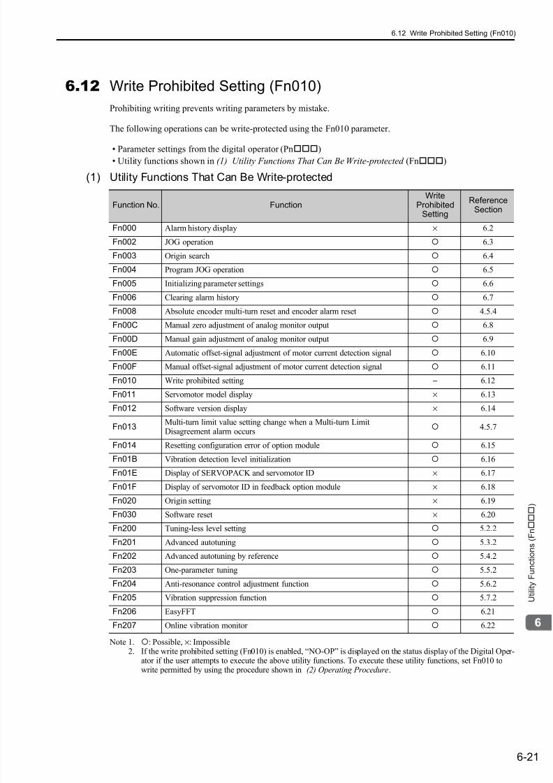
7/17/2019 Manual Yaskawa_servo_drive.pdf
http://slidepdf.com/reader/full/manual-yaskawaservodrivepdf 223/328
6.12 Write Prohibited Setting (Fn010)
6-21
U t i l i t y F u n c t i o n s ( F n )
6.12 Write Prohibited Setting (Fn010)
Prohibiting writing prevents writing parameters by mistake.
The following operations can be write-protected using the Fn010 parameter.
• Parameter settings from the digital operator (Pn)
• Utility functions shown in (1) Utility Functions That Can Be Write-protected (Fn)
(1) Utility Functions That Can Be Write-protected
Note 1. : Possible, ×: Impossible2. If the write prohibited setting (Fn010) is enabled, “NO-OP” is displayed on the status display of the Digital Oper-
ator if the user attempts to execute the above utility functions. To execute these utility functions, set Fn010 towrite permitted by using the procedure shown in (2) Operating Procedure.
Function No. FunctionWrite
ProhibitedSetting
ReferenceSection
Fn000 Alarm history display × 6.2
Fn002 JOG operation 6.3
Fn003 Origin search 6.4
Fn004 Program JOG operation 6.5
Fn005 Initializing parameter settings 6.6
Fn006 Clearing alarm history 6.7
Fn008 Absolute encoder multi-turn reset and encoder alarm reset 4.5.4
Fn00C Manual zero adjustment of analog monitor output 6.8
Fn00D Manual gain adjustment of analog monitor output 6.9
Fn00E Automatic offset-signal adjustment of motor current detection signal 6.10
Fn00F Manual offset-signal adjustment of motor current detection signal 6.11
Fn010 Write prohibited setting − 6.12
Fn011 Servomotor model display × 6.13
Fn012 Software version display × 6.14
Fn013Multi-turn limit value setting change when a Multi-turn LimitDisagreement alarm occurs
4.5.7
Fn014 Resetting configuration error of option module 6.15
Fn01B Vibration detection level initialization 6.16
Fn01E Display of SERVOPACK and servomotor ID × 6.17
Fn01F Display of servomotor ID in feedback option module × 6.18
Fn020 Origin setting × 6.19
Fn030 Software reset × 6.20
Fn200 Tuning-less level setting 5.2.2
Fn201 Advanced autotuning 5.3.2
Fn202 Advanced autotuning by reference 5.4.2
Fn203 One-parameter tuning 5.5.2
Fn204 Anti-resonance control adjustment function 5.6.2
Fn205 Vibration suppression function 5.7.2
Fn206 EasyFFT 6.21
Fn207 Online vibration monitor 6.22

7/17/2019 Manual Yaskawa_servo_drive.pdf
http://slidepdf.com/reader/full/manual-yaskawaservodrivepdf 224/328
6 Utility Functions (Fn)
6-22
(2) Operating Procedure
Follow the steps below to set “write prohibited” or “write permitted.”
Setting values are as follows:
• “P.0000”: Write permitted (Releases write prohibited mode.) [Factory setting]
• “P.0001”: Write prohibited (Parameters become write prohibited from the next power ON.)
Step Display Example Keys Description
1 Press the Key to open the Utility Function Modemain menu and select Fn010.
2 Press the Key. The display switches to theexecution display of Fn010.
3
Press the Key to select one of the following set-tings.
P.0000: Write permitted [Factory setting]P.0001: Write prohibited
4
Press the Key to save the setting value in the
SERVOPACK. When the saving is completed,“DONE” is displayed in the status display.
5 Press the Key to return to the Utility FunctionMode main menu.
6 Turn OFF the power and then turn it ON again to validate the new setting.
B B − F U N C T I O N −
F n 0 0 F : C u r M a n u A d j
F n 0 1 0 : P r m P r o t e c t
F n 0 1 1 : M o t o r I n f o
F n 0 1 2 : S o f t V e r
B B
P a r a m e t e r
W r i t e P r o t e c t
P . 0 0 0 0
B B
P a r a m e t e r
W r i t e P r o t e c t
P . 0 0 0 1
D O N E
P a r a m e t e r
W r i t e P r o t e c t
P . 0 0 0 1
B B − F U N C T I O N −
F n 0 0 F : C u r M a n u A d j
F n 0 1 0 : P r m P r o t e c t
F n 0 1 1 : M o t o r I n f o
F n 0 1 2 : S o f t V e r
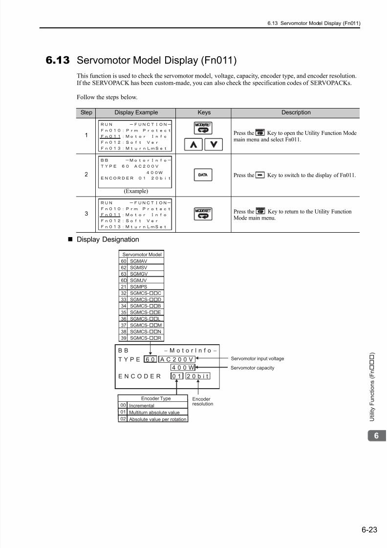
7/17/2019 Manual Yaskawa_servo_drive.pdf
http://slidepdf.com/reader/full/manual-yaskawaservodrivepdf 225/328
6.13 Servomotor Model Display (Fn011)
6-23
U t i l i t y F u n c t i o n s ( F n )
6.13 Servomotor Model Display (Fn011)
This function is used to check the servomotor model, voltage, capacity, encoder type, and encoder resolution.If the SERVOPACK has been custom-made, you can also check the specification codes of SERVOPACKs.
Follow the steps below.
Display Designation
Step Display Example Keys Description
1 Press the Key to open the Utility Function Modemain menu and select Fn011.
2 Press the Key to switch to the display of Fn011.
3 Press the Key to return to the Utility FunctionMode main menu.
(Example)
SGMAV
SGMSV
SGMGV
SGMJV
SGMPSSGMCS-C
SGMCS-D
SGMCS-B
SGMCS-E
SGMCS-L
SGMCS-M
SGMCS-N
SGMCS-R
00
01
E N C O D E R 0 1 2 0 b i t
B B − M o t o r l n f o −
T Y P E 6 0 A C 2 0 0 V
4 0 0 W
02
60
62
63
6D
2132
33
34
35
36
37
38
39
Servomotor capacity
Servomotor input voltage
Servomotor Model
Encoder Type
Incremental
Multiturn absolute value
Absolute value per rotation
Encoder resolution
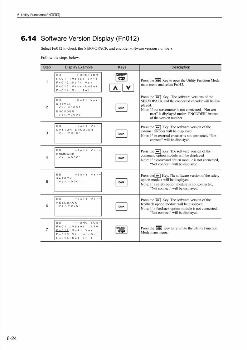
7/17/2019 Manual Yaskawa_servo_drive.pdf
http://slidepdf.com/reader/full/manual-yaskawaservodrivepdf 226/328
6 Utility Functions (Fn)
6-24
6.14 Software Version Display (Fn012)
Select Fn012 to check the SERVOPACK and encoder software version numbers.
Follow the steps below.
Step Display Example Keys Description
1 Press the Key to open the Utility Function Modemain menu and select Fn012.
2
Press the Key. The software versions of theSERVOPACK and the connected encoder will be dis- played.
Note: If the servomotor is not connected, “Not con-nect” is displayed under “ENCODER” insteadof the version number.
3
Press the Key. The software version of theexternal encoder will be displayed.
Note: If an external encoder is not connected, “Notconnect” will be displayed.
4
Press the Key. The software version of thecommand option module will be displayed.
Note: If a command option module is not connected,“Not connect” will be displayed.
5
Press the Key. The software version of the safetyoption module will be displayed.
Note: If a safety option module is not connected,“Not connect” will be displayed.
6
Press the Key. The software version of thefeedback option module will be displayed.
Note: If a feedback option module is not connected,“Not connect” will be displayed.
7 Press the Key to return to the Utility FunctionMode main menu.
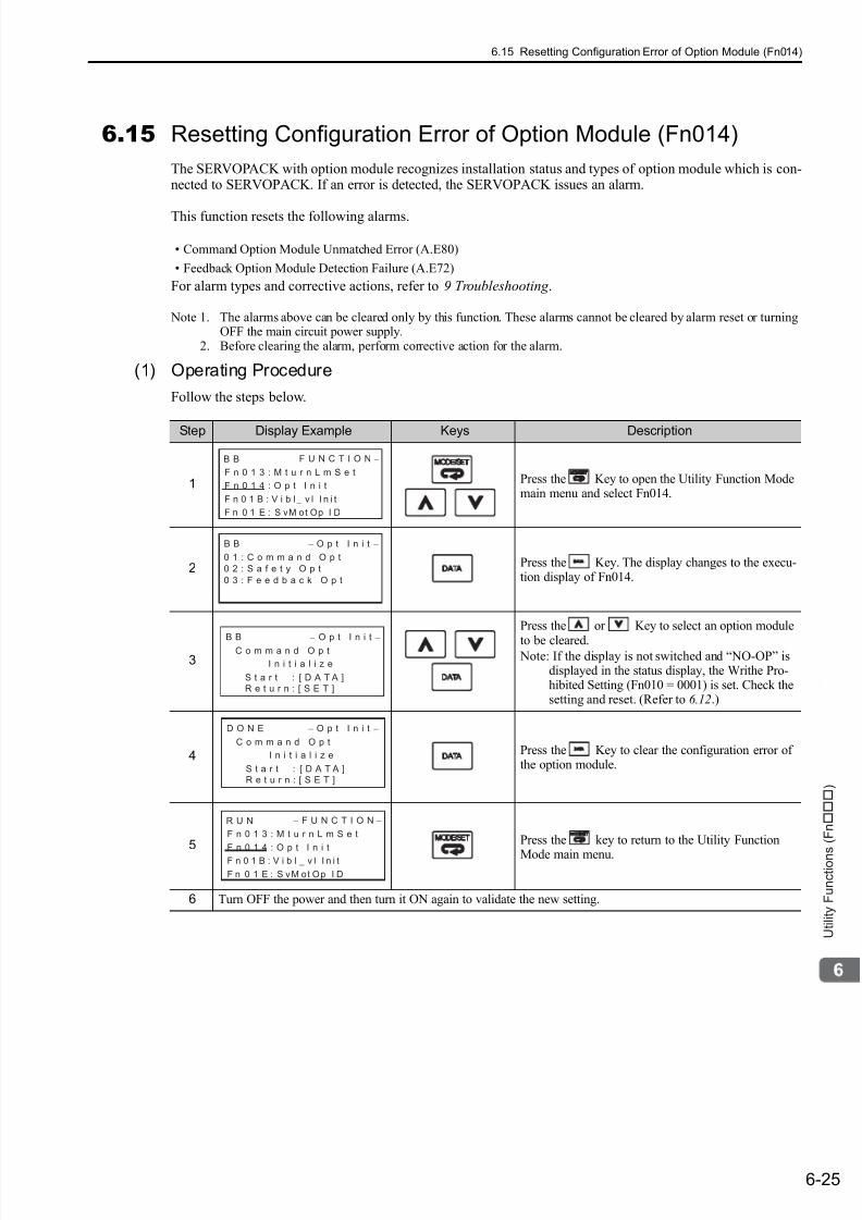
7/17/2019 Manual Yaskawa_servo_drive.pdf
http://slidepdf.com/reader/full/manual-yaskawaservodrivepdf 227/328
6.15 Resetting Configuration Error of Option Module (Fn014)
6-25
U t i l i t y F u n c t i o n s ( F n )
6.15 Resetting Configuration Error of Option Module (Fn014)
The SERVOPACK with option module recognizes installation status and types of option module which is con-nected to SERVOPACK. If an error is detected, the SERVOPACK issues an alarm.
This function resets the following alarms.
• Command Option Module Unmatched Error (A.E80)
• Feedback Option Module Detection Failure (A.E72)
For alarm types and corrective actions, refer to 9 Troubleshooting .
Note 1. The alarms above can be cleared only by this function. These alarms cannot be cleared by alarm reset or turningOFF the main circuit power supply.
2. Before clearing the alarm, perform corrective action for the alarm.
(1) Operating Procedure
Follow the steps below.
Step Display Example Keys Description
1 Press the Key to open the Utility Function Modemain menu and select Fn014.
2 Press the Key. The display changes to the execu-tion display of Fn014.
3
Press the or Key to select an option module
to be cleared. Note: If the display is not switched and “NO-OP” is
displayed in the status display, the Writhe Pro-hibited Setting (Fn010 = 0001) is set. Check thesetting and reset. (Refer to 6.12.)
4 Press the Key to clear the configuration error ofthe option module.
5 Press the key to return to the Utility Function
Mode main menu.
6 Turn OFF the power and then turn it ON again to validate the new setting.
B B − F U N C T I O N −
F n 0 1 3 : M t u r n L m S e t
F n 0 1 4 : O p t I n i t
F n 0 1 B : V i b l− v l I n i t
F n 0 1 E : S vM ot Op I D
B B − O p t I n i t −
0 1 : C o m m a n d O p t
0 2 : S a f e t y O p t
0 3 : F e e d b a c k O p t
B B − O p t I n i t −C o m m a n d O p t
I n i t i a l i z e
S t a r t : [ D A T A ]
R e t u r n : [ S E T ]
S t a r t : [ D A T A ]
R e t u r n : [ S E T ]
D O N E − O p t I n i t −
C o m m a n d O p t
I n i t i a l i z e
R U N − F U N C T I O N −
F n 0 1 3 : M t u r n L m S e t
F n 0 1 4 : O p t I n i t
F n 0 1 B : V i b l−
v l I n i t
F n 0 1 E : S vM ot Op I D
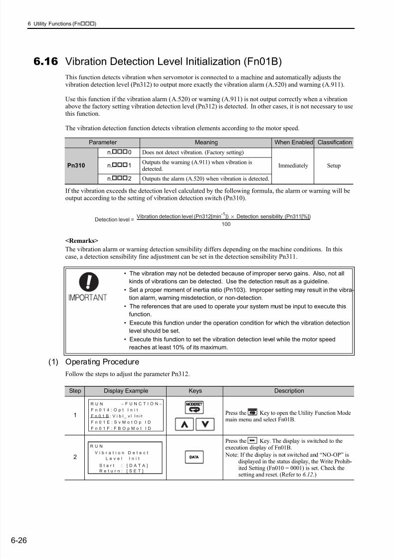
7/17/2019 Manual Yaskawa_servo_drive.pdf
http://slidepdf.com/reader/full/manual-yaskawaservodrivepdf 228/328
6 Utility Functions (Fn)
6-26
6.16 Vibration Detection Level Initialization (Fn01B)
This function detects vibration when servomotor is connected to a machine and automatically adjusts thevibration detection level (Pn312) to output more exactly the vibration alarm (A.520) and warning (A.911).
Use this function if the vibration alarm (A.520) or warning (A.911) is not output correctly when a vibrationabove the factory setting vibration detection level (Pn312) is detected. In other cases, it is not necessary to usethis function.
The vibration detection function detects vibration elements according to the motor speed.
If the vibration exceeds the detection level calculated by the following formula, the alarm or warning will be
output according to the setting of vibration detection switch (Pn310).
<Remarks>
The vibration alarm or warning detection sensibility differs depending on the machine conditions. In thiscase, a detection sensibility fine adjustment can be set in the detection sensibility Pn311.
(1) Operating Procedure
Follow the steps to adjust the parameter Pn312.
Parameter Meaning When Enabled Classification
Pn310
n. 0 Does not detect vibration. (Factory setting)
Immediately Setupn.
1Outputs the warning (A.911) when vibration isdetected.
n. 2 Outputs the alarm (A.520) when vibration is detected.
• The vibration may not be detected because of improper servo gains. Also, not all
kinds of vibrations can be detected. Use the detection result as a guideline.
• Set a proper moment of inertia ratio (Pn103). Improper setting may result in the vibra-
tion alarm, warning misdetection, or non-detection.
• The references that are used to operate your system must be input to execute this
function.
• Execute this function under the operation condition for which the vibration detection
level should be set.
• Execute this function to set the vibration detection level while the motor speed
reaches at least 10% of its maximum.
Detection level = Vibration detection level (Pn312[min
-1]) × Detection sensibility (Pn311[%])
100
Step Display Example Keys Description
1 Press the Key to open the Utility Function Modemain menu and select Fn01B.
2
Press the Key. The display is switched to theexecution display of Fn01B.
Note: If the display is not switched and “NO-OP” isdisplayed in the status display, the Write Prohib-ited Setting (Fn010 = 0001) is set. Check thesetting and reset. (Refer to 6.12.)
R U N − F U N C T I O N −
F n 0 1 4 : O p t I n i t
F n 0 1 B : V i b l−
v l I n i t
F n 0 1 E : S v M o t O p I D
F n 0 1 F : F B O p M o t I D
L e v e l I n i t
R U N
V i b r a t i o n D e t e c t
S t a r t : [ D A T A ]
R e t u r n : [ S E T ]
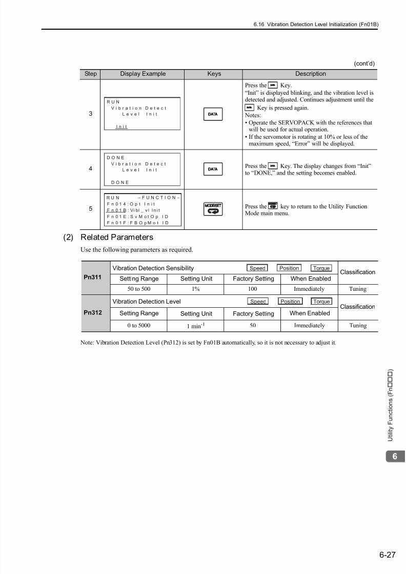
7/17/2019 Manual Yaskawa_servo_drive.pdf
http://slidepdf.com/reader/full/manual-yaskawaservodrivepdf 229/328
6.16 Vibration Detection Level Initialization (Fn01B)
6-27
U t i l i t y F u n c t i o n s ( F n )
(2) Related Parameters
Use the following parameters as required.
Note: Vibration Detection Level (Pn312) is set by Fn01B automatically, so it is not necessary to adjust it.
3
Press the Key.
“Init” is displayed blinking, and the vibration level is
detected and adjusted. Continues adjustment until theKey is pressed again.
Notes:
• Operate the SERVOPACK with the references thatwill be used for actual operation.
• If the servomotor is rotating at 10% or less of themaximum speed, “Error” will be displayed.
4 Press the Key. The display changes from “Init”to “DONE,” and the setting becomes enabled.
5 Press the key to return to the Utility FunctionMode main menu.
(cont’d)
Step Display Example Keys Description
L e v e l I n i t
R U N
V i b r a t i o n D e t e c t
I n i t
L e v e l I n i t
D O N E
V i b r a t i o n D e t e c t
D O N E
R U N − F U N C T I O N −
F n 0 1 4 : O p t I n i t
F n 0 1 B : Vi bl−
v l I n i t
F n 0 1 E : S v M o t O p I D
F n 0 1 F : F B O p M o t I D
Pn311
Vibration Detection SensibilityClassification
Setting Range Setting Unit Factory Setting When Enabled
50 to 500 1% 100 Immediately Tuning
Pn312
Vibration Detection Level ClassificationSetting Range Setting Unit Factory Setting When Enabled
0 to 5000 1 min-1 50 Immediately Tuning
Speed Position Torque
Speed Position Torque
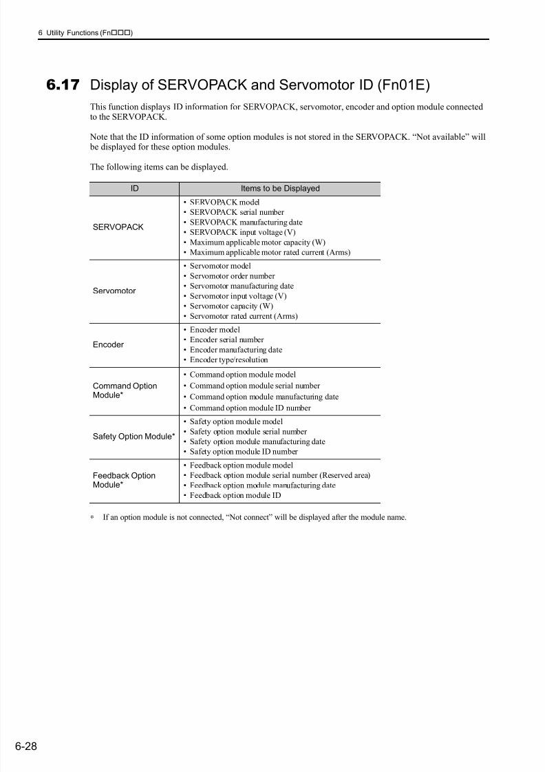
7/17/2019 Manual Yaskawa_servo_drive.pdf
http://slidepdf.com/reader/full/manual-yaskawaservodrivepdf 230/328
6 Utility Functions (Fn)
6-28
6.17 Display of SERVOPACK and Servomotor ID (Fn01E)
This function displays ID information for SERVOPACK, servomotor, encoder and option module connectedto the SERVOPACK.
Note that the ID information of some option modules is not stored in the SERVOPACK. “Not available” will be displayed for these option modules.
The following items can be displayed.
∗ If an option module is not connected, “Not connect” will be displayed after the module name.
ID Items to be Displayed
SERVOPACK
• SERVOPACK model
• SERVOPACK serial number
• SERVOPACK manufacturing date
• SERVOPACK input voltage (V)
• Maximum applicable motor capacity (W)
• Maximum applicable motor rated current (Arms)
Servomotor
• Servomotor model
• Servomotor order number
• Servomotor manufacturing date
• Servomotor input voltage (V)
• Servomotor capacity (W)
• Servomotor rated current (Arms)
Encoder
• Encoder model
• Encoder serial number
• Encoder manufacturing date
• Encoder type/resolution
Command OptionModule*
• Command option module model
• Command option module serial number
• Command option module manufacturing date
• Command option module ID number
Safety Option Module*
• Safety option module model
• Safety option module serial number
• Safety option module manufacturing date
• Safety option module ID number
Feedback OptionModule*
• Feedback option module model
• Feedback option module serial number (Reserved area)
• Feedback option module manufacturing date
• Feedback option module ID
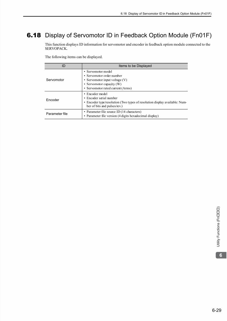
7/17/2019 Manual Yaskawa_servo_drive.pdf
http://slidepdf.com/reader/full/manual-yaskawaservodrivepdf 231/328
6.18 Display of Servomotor ID in Feedback Option Module (Fn01F)
6-29
U t i l i t y F u n c t i o n s ( F n )
6.18 Display of Servomotor ID in Feedback Option Module (Fn01F)
This function displays ID information for servomotor and encoder in feedback option module connected to theSERVOPACK.
The following items can be displayed.
ID Items to be Displayed
Servomotor
• Servomotor model
• Servomotor order number
• Servomotor input voltage (V)
• Servomotor capacity (W)
• Servomotor rated current (Arms)
Encoder
• Encoder model
• Encoder serial number
• Encoder type/resolution (Two types of resolution display available: Num- ber of bits and pulses/rev.)
Parameter file • Parameter file source ID (14 characters)• Parameter file version (4 digits hexadecimal display)
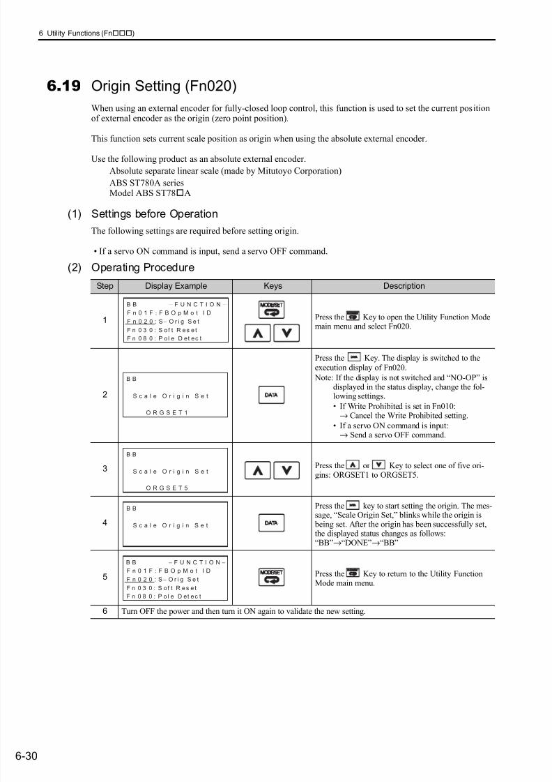
7/17/2019 Manual Yaskawa_servo_drive.pdf
http://slidepdf.com/reader/full/manual-yaskawaservodrivepdf 232/328
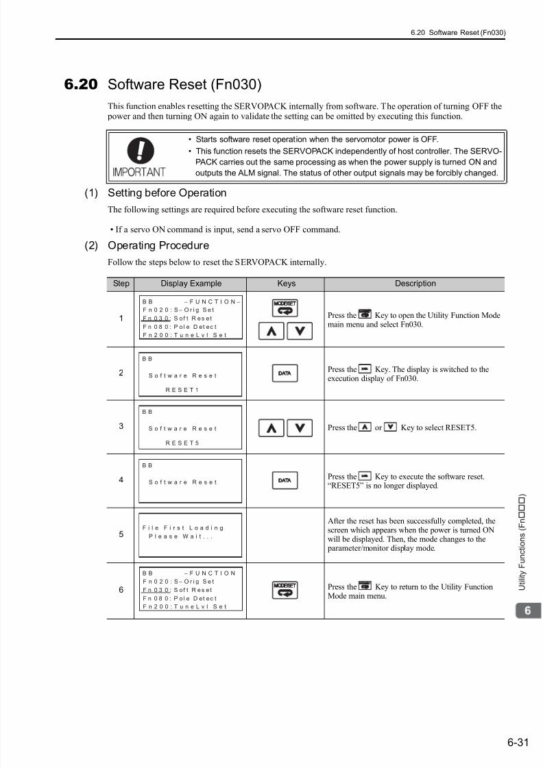
7/17/2019 Manual Yaskawa_servo_drive.pdf
http://slidepdf.com/reader/full/manual-yaskawaservodrivepdf 233/328
6.20 Software Reset (Fn030)
6-31
U t i l i t y F u n c t i o n s ( F n )
6.20 Software Reset (Fn030)
This function enables resetting the SERVOPACK internally from software. The operation of turning OFF the power and then turning ON again to validate the setting can be omitted by executing this function.
(1) Setting before Operation
The following settings are required before executing the software reset function.
• If a servo ON command is input, send a servo OFF command.
(2) Operating Procedure
Follow the steps below to reset the SERVOPACK internally.
• Starts software reset operation when the servomotor power is OFF.
• This function resets the SERVOPACK independently of host controller. The SERVO-
PACK carries out the same processing as when the power supply is turned ON and
outputs the ALM signal. The status of other output signals may be forcibly changed.
Step Display Example Keys Description
1 Press the Key to open the Utility Function Modemain menu and select Fn030.
2 Press the Key. The display is switched to theexecution display of Fn030.
3 Press the or Key to select RESET5.
4 Press the Key to execute the software reset.“RESET5” is no longer displayed.
5
After the reset has been successfully completed, thescreen which appears when the power is turned ON
will be displayed. Then, the mode changes to the parameter/monitor display mode.
6 Press the Key to return to the Utility FunctionMode main menu.
B B − F U N C T I O N −
F n 0 2 0 : S − O r i g S e t
F n 0 3 0 : S of t R es e t
F n 0 8 0 : P o l e D et ec t
F n 2 0 0 : T u n e L v l S e t
B B
S o f t w a r e R e s e t
R E S E T 1
B B
S o f t w a r e R e s e t
R E S E T 5
B B
S o f t w a r e R e s e t
F i l e F i r s t L o a d i n g
P l e a s e W a i t . . .
B B − F U N C T I O N −
F n 0 2 0 : S − O r i g S e t
F n 0 3 0 : S of t R es e t
F n 0 8 0 : P o l e D et ec t
F n 2 0 0 : T u n e L v l S e t
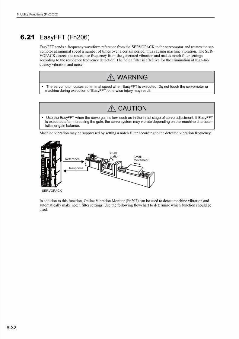
7/17/2019 Manual Yaskawa_servo_drive.pdf
http://slidepdf.com/reader/full/manual-yaskawaservodrivepdf 234/328
6 Utility Functions (Fn)
6-32
6.21 EasyFFT (Fn206)
EasyFFT sends a frequency waveform reference from the SERVOPACK to the servomotor and rotates the ser-vomotor at minimal speed a number of times over a certain period, thus causing machine vibration. The SER-VOPACK detects the resonance frequency from the generated vibration and makes notch filter settings
according to the resonance frequency detection. The notch filter is effective for the elimination of high-fre-quency vibration and noise.
Machine vibration may be suppressed by setting a notch filter according to the detected vibration frequency.
In addition to this function, Online Vibration Monitor (Fn207) can be used to detect machine vibration andautomatically make notch filter settings. Use the following flowchart to determine which function should beused.
WARNING
• The servomotor rotates at minimal speed when EasyFFT is executed. Do not touch the servomotor ormachine during execution of EasyFFT, otherwise injury may result.
CAUTION
• Use the EasyFFT when the servo gain is low, such as in the initial stage of servo adjustment. If EasyFFTis executed after increasing the gain, the servo system may vibrate depending on the machine character-istics or gain balance.
Smallrotation Small
movement
SERVOPACK
Reference
Response
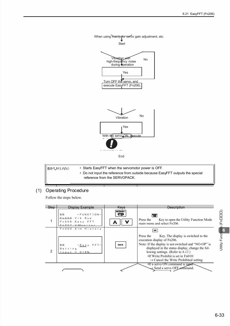
7/17/2019 Manual Yaskawa_servo_drive.pdf
http://slidepdf.com/reader/full/manual-yaskawaservodrivepdf 235/328
6.21 EasyFFT (Fn206)
6-33
U t i l i t y F u n c t i o n s ( F n )
(1) Operating Procedure
Follow the steps below.
• Starts EasyFFT when the servomotor power is OFF.
• Do not input the reference from outside because EasyFFT outputs the special
reference from the SERVOPACK.
Start
When using mainly for servo gain adjustment, etc.
End
Vibration withhigh-frequency noise
during operation
Turn OFF the servo, and
execute EasyFFT (Fn206).
No
No
Yes
Yes
Adjust servo gain.
Vibration
With the servo ON, execute
Online Vibration Monitor
(Fn207).
Step Display Example Keys Description
1 Press the Key to open the Utility Function Modemain menu and select Fn206.
2
Press the Key. The display is switched to the
execution display of Fn206.
Note: If the display is not switched and “NO-OP” isdisplayed in the status display, change the fol-lowing settings. (Refer to 6.12.)
•If Write Prohibit is set in Fn010:→ Cancel the Write Prohibited setting.
•If a servo ON command is input:→ Send a servo OFF command.

7/17/2019 Manual Yaskawa_servo_drive.pdf
http://slidepdf.com/reader/full/manual-yaskawaservodrivepdf 236/328
6 Utility Functions (Fn)
6-34
3
The cursor is on the setting of "Input." Press
the or Key to set the sweep torque
reference amplitude (Pn456)Setting range: 1 to 800.
Note:When making the initial settings for EasyFFT,do not change the setting for the referenceamplitude. Start with the original value of 15.Increasing reference amplitude increases thedetection accuracy, but the vibration and noisefrom the machine will increase. Increase theamplitude value little by little.
4Press the Key to turn the servomotor power ON.The display “BB” and “Setting” changes to “RUN”and “Ready.”
5
Press the (forward run start) Key or
(reverse run start) Key to run the servomotor and startthe frequency measurement. "Measure" is displayed blinking during the measurement.
Within a quarter turn, the servomotor will moveforward and then in reverse several times. The totaloperation time is between 1 and 45 seconds.
Note:The actions of the servomotor are very minutein this operation. Also at the same time, the ser-vomotor emits a noise. To ensure safety, do notenter the working envelope of the motor.
6
When the detection has completed normally, theresult and the notch filter value to be set are dis-
played.
Press the Key to turn OFF the power to the
servomotor.
< Important >
If 2 seconds or more are required for the operationalthough detection was successfully completed, thedetection accuracy might be insufficient. Increasingreference amplitude more than 15 increases thedetection accuracy, but the vibration and noise fromthe machine will increase. Increase the amplitudevalue little by little.
Notes:
• If a notch filter has been set and is being used, "*"is displayed on the second line.
• If the first notch filter has been set, the secondnotch filter value is displayed. If the first andsecond notch filters have been set, only the resultof frequency detection is displayed.
• If the Key is pressed while the servomotor is
running, the servomotor will stop, and the fre-quency detection will be canceled.
• If the detection is not completed normally, “NoMeasure” is displayed.
7
Press the Key to exit the EasyFFT function at
this stage. The power to the servomotor is turned OFFand the display returns to the Utility Function Modemain menu.
Press the Key to return to "Ready" display.
(cont’d)
Step Display Example Keys Description

7/17/2019 Manual Yaskawa_servo_drive.pdf
http://slidepdf.com/reader/full/manual-yaskawaservodrivepdf 237/328
6.21 EasyFFT (Fn206)
6-35
U t i l i t y F u n c t i o n s ( F n )
(2) Related Parameters
The Easy FFT related parameters are listed below. These parameters will be automatically set and the userneed not set them manually.
8
Press the Key after the normal completion of
frequency detection. The notch filter frequencies are
updated to the optimum values. If the first notch filterfrequency has been set, set the second notch filterfrequency (Pn 40C) to Pn 408.0 = 1.
Notes:
• If the second stage notch filter frequency hasalready been set (Pn408.2 = 1), the notch filterfrequency cannot be set.
• If the frequency detected by this function is notused, set the notch filter to be invalid (Pn408.0 = 0).
9 Press the Key to return to the Utility FunctionMode main menu.
10 Turn OFF the power and then turn ON again to validate the setting.
(cont’d)
Step Display Example Keys Description
Parameter Meaning When Enabled Classification
Pn408
n. 0 Disables 1st notch filter. (Factory setting)
Immediately Setupn. 1 Uses 1st notch filter.
n. 0 Disables 2nd notch filter. (Factory setting)
n. 1 Uses 2nd notch filter.
Pn409
1st Notch FIlter FrequencyClassification
Setting Range Setting Unit Factory Setting When Enabled
50 to 5000 1 Hz 5000 Immediately Tuning
Pn40C
2nd Notch FIlter FrequencyClassification
Setting Range Setting Unit Factory Setting When Enabled
50 to 5000 1 Hz 5000 Immediately Tuning
Pn456
Sweep Torque Reference AmplitudeClassification
Setting Range Setting Unit Factory Setting When Enabled
1 to 800 1% 15 Immediately Tuning
Speed Position Torque
Speed Position Torque
Speed Position Torque
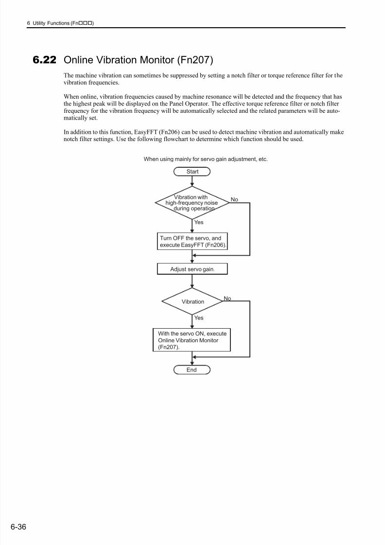
7/17/2019 Manual Yaskawa_servo_drive.pdf
http://slidepdf.com/reader/full/manual-yaskawaservodrivepdf 238/328
6 Utility Functions (Fn)
6-36
6.22 Online Vibration Monitor (Fn207)
The machine vibration can sometimes be suppressed by setting a notch filter or torque reference filter for thevibration frequencies.
When online, vibration frequencies caused by machine resonance will be detected and the frequency that hasthe highest peak will be displayed on the Panel Operator. The effective torque reference filter or notch filterfrequency for the vibration frequency will be automatically selected and the related parameters will be auto-matically set.
In addition to this function, EasyFFT (Fn206) can be used to detect machine vibration and automatically makenotch filter settings. Use the following flowchart to determine which function should be used.
Start
When using mainly for servo gain adjustment, etc.
End
Vibration withhigh-frequency noise
during operation
Turn OFF the servo, and
execute EasyFFT (Fn206).
No
No
Yes
Yes
Adjust servo gain.
Vibration
With the servo ON, execute
Online Vibration Monitor
(Fn207).

7/17/2019 Manual Yaskawa_servo_drive.pdf
http://slidepdf.com/reader/full/manual-yaskawaservodrivepdf 239/328
6.22 Online Vibration Monitor (Fn207)
6-37
U t i l i t y F u n c t i o n s ( F n )
(1) Operating Procedure
Follow the steps below.
(2) Related Parameters
The following parameters are set automatically by using online vibration monitor.
Step Display Example Keys Description
1 Press the Key to open the Utility Function Modemain menu and select Fn207.
2
Press the Key. The display is switched to theexecution display of Fn207.
Note: If the display is not switched and “NO-OP” isdisplayed in the status display, the Write Pro-hibit is set in Fn010. Check the setting andreset. (Refer to 6.12.)
3
Press the Key for 1 second.
The message, “Measure,” blinks, and vibration detec-tion will start.
4
When the vibration detection has completed, “Mea-sure” stops blinking and the detection ends automati-cally. When the detection has completed normally,the vibrations with three largest peak values in vibra-tion frequency are displayed for F1, F2, and F3.
Notes:
• Press the Key to quit the online vibrationmonitor function. The display returns to the UtilityFunction Mode main menu.
• Three detected frequencies can be displayed. For avibration with undetectable peak frequency, “----”
is displayed. If no frequency was detected, “----” isdisplayed for F1, F2, and F3.
• If the frequency could not be successfully detected,“NO MONITOR” is displayed.
5
After the detection has normally completed, press the
Key. The optimum frequency (time constant) ofnotch filter or torque reference filter for F1 is setautomatically. At the same time, the parameter Pn409is updated for a notch filter, or the parameter Pn401 isupdated for a torque reference filter.
6 Press the Key to return to the Utility FunctionMode main menu.
Parameter Meaning
Pn401 1st Step 1st Primary Torque Reference Filter Time Constant
Pn408 Torque Related Function Switch
Pn409 1st Notch Filter Frequency
7/17/2019 Manual Yaskawa_servo_drive.pdf
http://slidepdf.com/reader/full/manual-yaskawaservodrivepdf 240/3287-1
M o n i t o r M o d e s ( U n )
7
Monitor Modes (Un)
7.1 List of Monitor Modes . . . . . . . . . . . . . . . . . . . . . . . . . . . . . . . . . . . . . . . . .7-2
7.2 Monitor Displays . . . . . . . . . . . . . . . . . . . . . . . . . . . . . . . . . . . . . . . . . . . .7-3
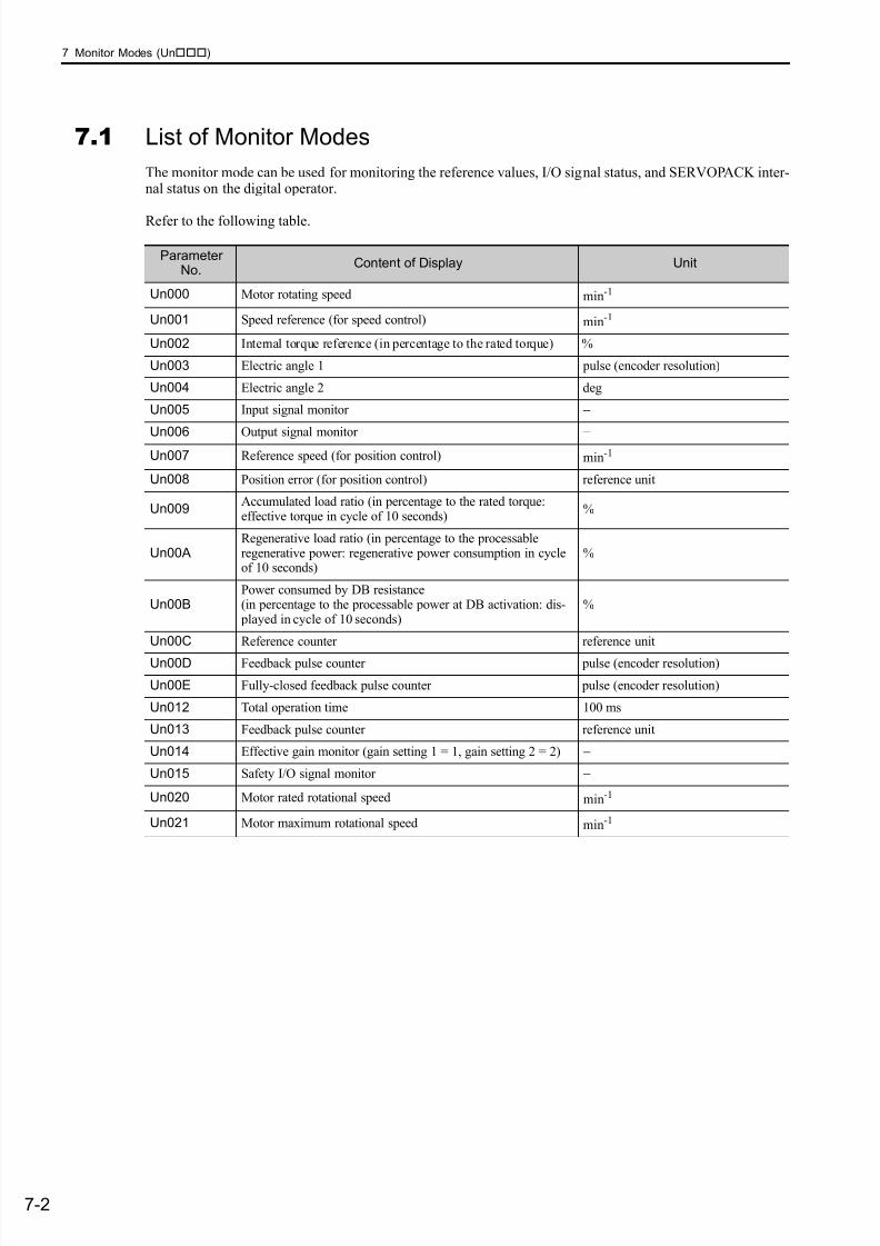
7/17/2019 Manual Yaskawa_servo_drive.pdf
http://slidepdf.com/reader/full/manual-yaskawaservodrivepdf 241/328
7 Monitor Modes (Un)
7-2
7.1 List of Monitor Modes
The monitor mode can be used for monitoring the reference values, I/O signal status, and SERVOPACK inter-nal status on the digital operator.
Refer to the following table.
ParameterNo.
Content of Display Unit
Un000 Motor rotating speed min-1
Un001 Speed reference (for speed control) min-1
Un002 Internal torque reference (in percentage to the rated torque) %
Un003 Electric angle 1 pulse (encoder resolution)
Un004 Electric angle 2 deg
Un005 Input signal monitor −
Un006 Output signal monitor −Un007 Reference speed (for position control) min-1
Un008 Position error (for position control) reference unit
Un009Accumulated load ratio (in percentage to the rated torque:effective torque in cycle of 10 seconds)
%
Un00ARegenerative load ratio (in percentage to the processableregenerative power: regenerative power consumption in cycleof 10 seconds)
%
Un00BPower consumed by DB resistance(in percentage to the processable power at DB activation: dis- played in cycle of 10 seconds)
%
Un00C Reference counter reference unit
Un00D Feedback pulse counter pulse (encoder resolution)
Un00E Fully-closed feedback pulse counter pulse (encoder resolution)
Un012 Total operation time 100 ms
Un013 Feedback pulse counter reference unit
Un014 Effective gain monitor (gain setting 1 = 1, gain setting 2 = 2) −
Un015 Safety I/O signal monitor −
Un020 Motor rated rotational speed min-1
Un021 Motor maximum rotational speed min-1
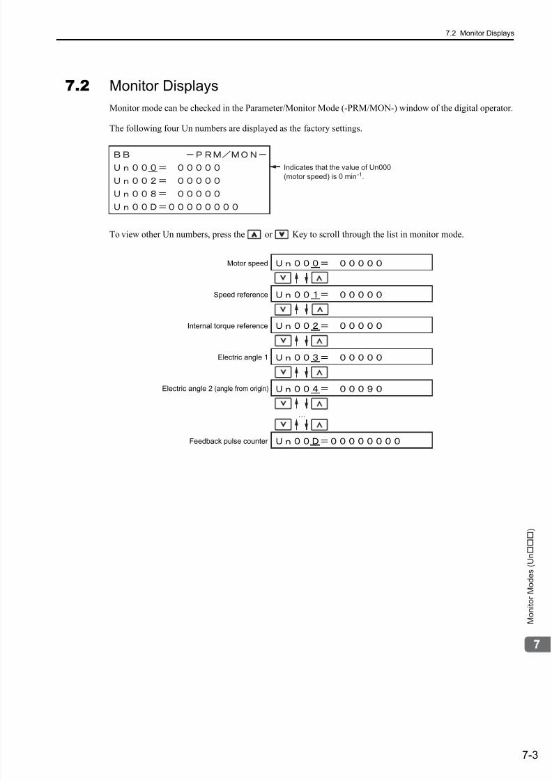
7/17/2019 Manual Yaskawa_servo_drive.pdf
http://slidepdf.com/reader/full/manual-yaskawaservodrivepdf 242/328
7.2 Monitor Displays
7-3
M o n i t o r M o d e s ( U n )
7.2 Monitor Displays
Monitor mode can be checked in the Parameter/Monitor Mode (-PRM/MON-) window of the digital operator.
The following four Un numbers are displayed as the factory settings.
To view other Un numbers, press the or Key to scroll through the list in monitor mode.
Indicates that the value of Un000
(motor speed) is 0 min-1.
Electric angle 1
Electric angle 2 (angle from origin)
…
Motor speed
Speed reference
Feedback pulse counter
Internal torque reference

7/17/2019 Manual Yaskawa_servo_drive.pdf
http://slidepdf.com/reader/full/manual-yaskawaservodrivepdf 243/3288-1
F u l l y - c l o s e d L o o p C o n t r o l
8
Fully-closed Loop Control
8.1 System Configuration and Connection Example for
SERVOPACK with Fully-closed Loop Control . . . . . . . . . . . . . . . . . . . . .8-2
8.1.1 System Configuration . . . . . . . . . . . . . . . . . . . . . . . . . . . . . . . . . . . . . . . . . . . . . . . . . 8-2
8.1.2 Internal Block Diagram of Fully-closed Loop Control . . . . . . . . . . . . . . . . . . . . . . . . . 8-3
8.1.3 Serial Converter Unit . . . . . . . . . . . . . . . . . . . . . . . . . . . . . . . . . . . . . . . . . . . . . . . . . . 8-4
8.1.4 Example of Connections to External Encoders . . . . . . . . . . . . . . . . . . . . . . . . . . . . . . 8-6
8.1.5 Encoder Output Pulse Signals from SERVOPACK with an External Encoder
by Renishaw plc . . . . . . . . . . . . . . . . . . . . . . . . . . . . . . . . . . . . . . . . . . . . . . . . . . . . . 8-7
8.1.6 Precautions When Using an External Incremental Encoder by Magnescale . . . . . . . 8-8
8.2 SERVOPACK Startup Procedure . . . . . . . . . . . . . . . . . . . . . . . . . . . . . .8-12
8.3 Parameter Settings for Fully-closed Loop Control . . . . . . . . . . . . . . . . .8-14
8.3.1 Motor Rotation Direction . . . . . . . . . . . . . . . . . . . . . . . . . . . . . . . . . . . . . . . . . . . . . . 8-15
8.3.2 Sine Wave Pitch (Frequency) for an External Encoder . . . . . . . . . . . . . . . . . . . . . . . 8-17
8.3.3 Setting Encoder Output Pulses (PAO, PBO, and PCO) . . . . . . . . . . . . . . . . . . . . . . 8-17
8.3.4 External Absolute Encoder Data Reception Sequence . . . . . . . . . . . . . . . . . . . . . . . 8-18
8.3.5 Electronic Gear . . . . . . . . . . . . . . . . . . . . . . . . . . . . . . . . . . . . . . . . . . . . . . . . . . . . . 8-21
8.3.6 Alarm Detection . . . . . . . . . . . . . . . . . . . . . . . . . . . . . . . . . . . . . . . . . . . . . . . . . . . . . 8-22
8.3.7 Analog Monitor Signal . . . . . . . . . . . . . . . . . . . . . . . . . . . . . . . . . . . . . . . . . . . . . . . . 8-23
8.3.8 Speed Feedback Method during Fully-closed Loop Control . . . . . . . . . . . . . . . . . . . 8-23
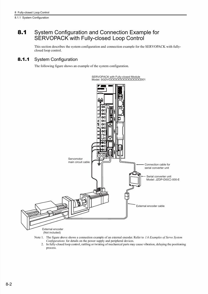
7/17/2019 Manual Yaskawa_servo_drive.pdf
http://slidepdf.com/reader/full/manual-yaskawaservodrivepdf 244/328
8 Fully-closed Loop Control
8.1.1 System Configuration
8-2
8.1 System Configuration and Connection Example forSERVOPACK with Fully-closed Loop Control
This section describes the system configuration and connection example for the SERVOPACK with fully-
closed loop control.
8.1.1 System Configuration
The following figure shows an example of the system configuration.
Note 1. The figure above shows a connection example of an external encoder. Refer to 1.6 Examples of Servo SystemConfigurations for details on the power supply and peripheral devices.
2. In fully-closed loop control, rattling or twisting of mechanical parts may cause vibration, delaying the positioning process.
Serial converter unit
External encoder cable
Connection cable for
serial converter unit
External encoder
(Not included)
Servomotormain circuit cable
Model: JZDP-D00-000-E
SERVOPACK with Fully-closed ModuleModel: SGDV001
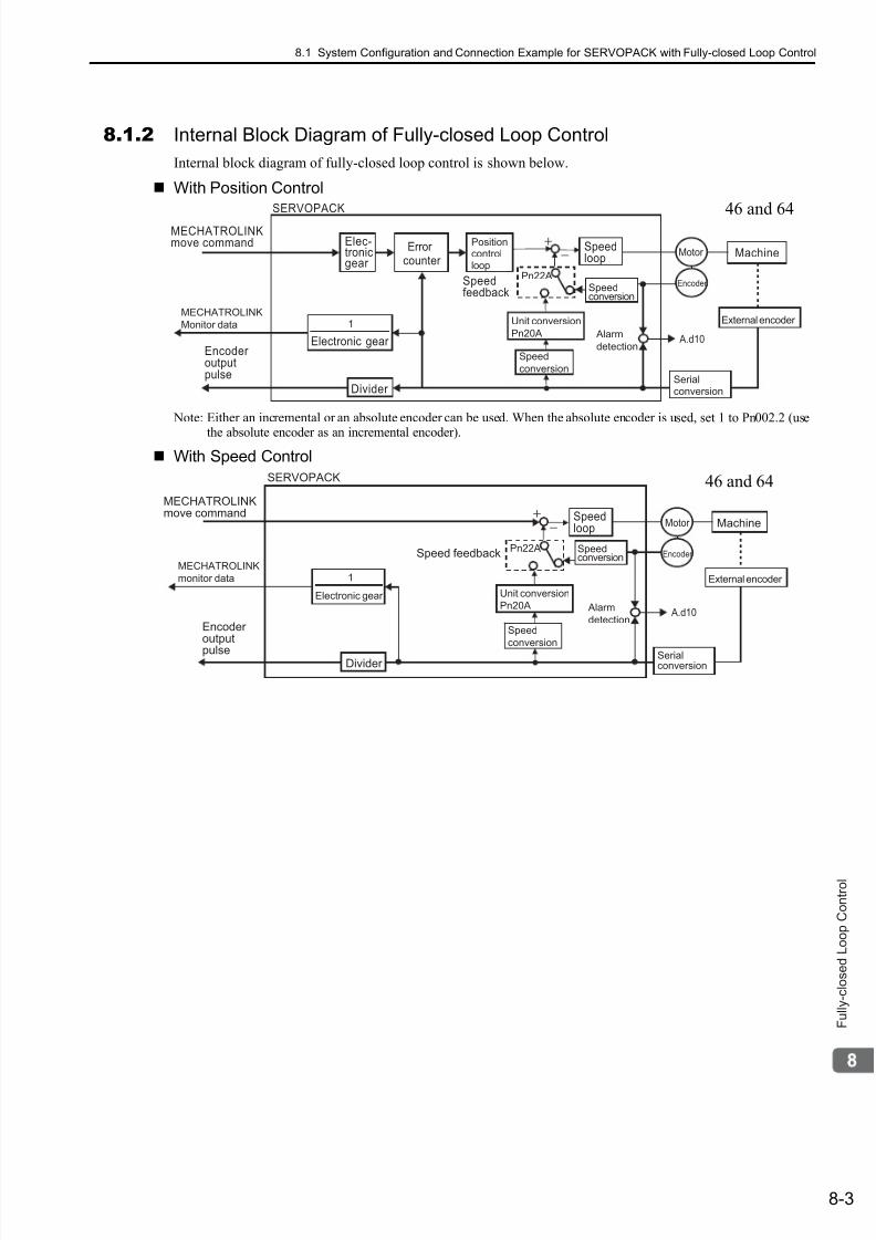
7/17/2019 Manual Yaskawa_servo_drive.pdf
http://slidepdf.com/reader/full/manual-yaskawaservodrivepdf 245/328
8.1 System Configuration and Connection Example for SERVOPACK with Fully-closed Loop Control
8-3
F u l l y - c l o s e d L o o p C o n t r o l
8.1.2 Internal Block Diagram of Fully-closed Loop Control
Internal block diagram of fully-closed loop control is shown below.
With Position Control
Note: Either an incremental or an absolute encoder can be used. When the absolute encoder is used, set 1 to Pn002.2 (use
the absolute encoder as an incremental encoder).
With Speed Control
Elec-tronicgear
MECHATROLINKmove command
Encoder outputpulse
Errorcounter
Speedloop
Alarm
detection
Divider
Machine
SERVOPACK
Positioncontrolloop
Serialconversion
Motor
A.d10
Encoder
External encoder
Speedconversion
Speedfeedback
Electronic gear
1MECHATROLINK
Monitor data
Pn22A
Speed
conversion
Unit conversion
Pn20A
46 and 64
SERVOPACK
Encoder output
pulseDivider
Speedloop MachineMotor
Encoder
External encoder
SpeedconversionSpeed feedback
Serialconversion
MECHATROLINKmove command
Electronic gear
1MECHATROLINK
monitor data
Pn22A
Speed
conversion
Unit conversion
Pn20A Alarm
detection A.d10
46 and 64
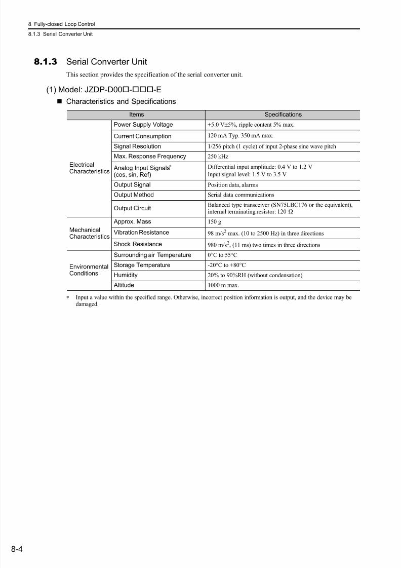
7/17/2019 Manual Yaskawa_servo_drive.pdf
http://slidepdf.com/reader/full/manual-yaskawaservodrivepdf 246/328
8 Fully-closed Loop Control
8.1.3 Serial Converter Unit
8-4
8.1.3 Serial Converter Unit
This section provides the specification of the serial converter unit.
(1) Model: JZDP-D00--E
Characteristics and Specifications
∗ Input a value within the specified range. Otherwise, incorrect position information is output, and the device may bedamaged.
Items Specifications
ElectricalCharacteristics
Power Supply Voltage +5.0 V±5%, ripple content 5% max.
Current Consumption 120 mA Typ. 350 mA max.
Signal Resolution 1/256 pitch (1 cycle) of input 2-phase sine wave pitch
Max. Response Frequency 250 kHz
Analog Input Signals∗
(cos, sin, Ref)
Differential input amplitude: 0.4 V to 1.2 V
Input signal level: 1.5 V to 3.5 V
Output Signal Position data, alarms
Output Method Serial data communications
Output CircuitBalanced type transceiver (SN75LBC176 or the equivalent),internal terminating resistor: 120 Ω
MechanicalCharacteristics
Approx. Mass 150 g
Vibration Resistance 98 m/s2 max. (10 to 2500 Hz) in three directions
Shock Resistance 980 m/s2, (11 ms) two times in three directions
EnvironmentalConditions
Surrounding air Temperature 0°C to 55°C
Storage Temperature -20°C to +80°C
Humidity 20% to 90%RH (without condensation)
Altitude 1000 m max.
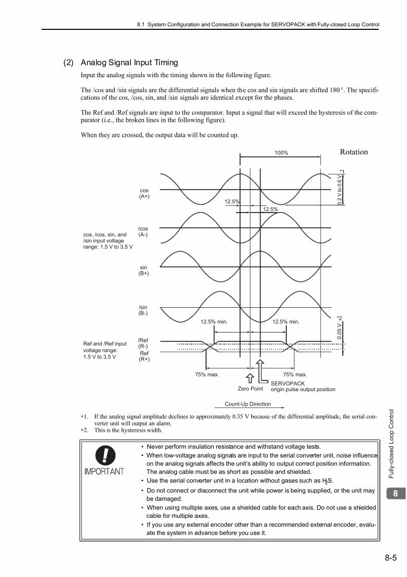
7/17/2019 Manual Yaskawa_servo_drive.pdf
http://slidepdf.com/reader/full/manual-yaskawaservodrivepdf 247/328
8.1 System Configuration and Connection Example for SERVOPACK with Fully-closed Loop Control
8-5
F u l l y - c l o s e d L o o p C o n t r o l
(2) Analog Signal Input Timing
Input the analog signals with the timing shown in the following figure.
The /cos and /sin signals are the differential signals when the cos and sin signals are shifted 180°. The specifi-
cations of the cos, /cos, sin, and /sin signals are identical except for the phases.
The Ref and /Ref signals are input to the comparator. Input a signal that will exceed the hysteresis of the com- parator (i.e., the broken lines in the following figure).
When they are crossed, the output data will be counted up.
∗1. If the analog signal amplitude declines to approximately 0.35 V because of the differential amplitude, the serial con-verter unit will output an alarm.
∗2. This is the hysteresis width.
• Never perform insulation resistance and withstand voltage tests.
• When low-voltage analog signals are input to the serial converter unit, noise influence
on the analog signals affects the unit’s ability to output correct position information.
The analog cable must be as short as possible and shielded.
• Use the serial converter unit in a location without gases such as H2S.
• Do not connect or disconnect the unit while power is being supplied, or the unit may
be damaged.
• When using multiple axes, use a shielded cable for each axis. Do not use a shielded
cable for multiple axes.
• If you use any external encoder other than a recommended external encoder, evalu-
ate the system in advance before you use it.
100%
12.5%
75% max. 75% max.
12.5% min. 12.5% min.
Zero Point
Count-Up Direction
0 . 0
5 V
cos(A+)
/cos(A-)
sin(B+)
/sin(B-)
/Ref (R-)
Ref (R+)
*2
*1
SERVOPACKorigin pulse output position
12.5%
Ref and /Ref input
voltage range:
1.5 V to 3.5 V
cos, /cos, sin, and/sin input voltagerange: 1.5 V to 3.5 V
0 . 2
V t o
0 . 6
V
Rotation
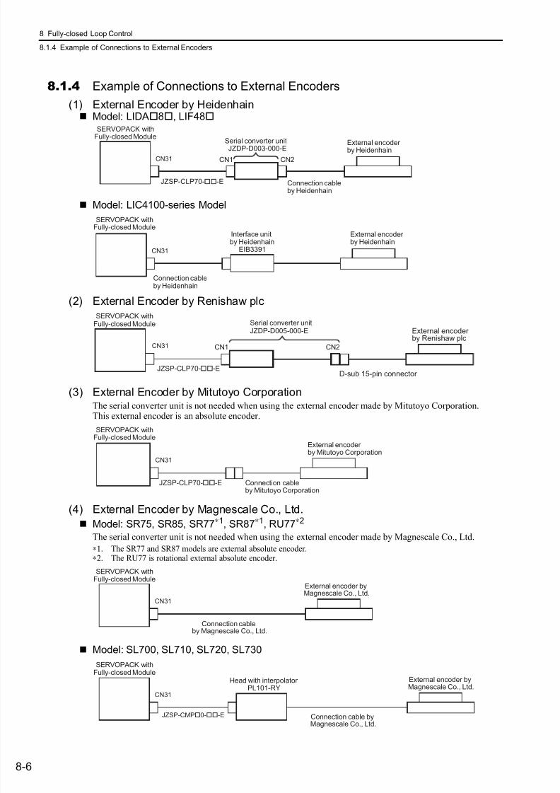
7/17/2019 Manual Yaskawa_servo_drive.pdf
http://slidepdf.com/reader/full/manual-yaskawaservodrivepdf 248/328
8 Fully-closed Loop Control
8.1.4 Example of Connections to External Encoders
8-6
8.1.4 Example of Connections to External Encoders
(1) External Encoder by Heidenhain Model: LIDA8, LIF48
Model: LIC4100-series Model
(2) External Encoder by Renishaw plc
(3) External Encoder by Mitutoyo CorporationThe serial converter unit is not needed when using the external encoder made by Mitutoyo Corporation.
This external encoder is an absolute encoder.
(4) External Encoder by Magnescale Co., Ltd.
Model: SR75, SR85, SR77∗1, SR87∗1, RU77∗2
The serial converter unit is not needed when using the external encoder made by Magnescale Co., Ltd.
∗1. The SR77 and SR87 models are external absolute encoder.
∗2. The RU77 is rotational external absolute encoder.
Model: SL700, SL710, SL720, SL730
CN31
JZSP-CLP70--E
CN1 CN2
SERVOPACK with
Fully-closed Module Serial converter unit
Connection cableby Heidenhain
External encoder by HeidenhainJZDP-D003-000-E
SERVOPACK withFully-closed Module
CN31
Interface unitby Heidenhain
EIB3391
Connection cableby Heidenhain
External encoder by Heidenhain
CN1 CN2CN31
JZSP-CLP70--E
Serial converter unitJZDP-D005-000-E External encoder
by Renishaw plc
D-sub 15-pin connector
SERVOPACK withFully-closed Module
CN31
JZSP-CLP70--E Connection cableby Mitutoyo Corporation
External encoder by Mitutoyo Corporation
SERVOPACK withFully-closed Module
CN31
Connection cableby Magnescale Co., Ltd.
External encoder byMagnescale Co., Ltd.
SERVOPACK withFully-closed Module
CN31
JZSP-CMP0--E
Head with interpolator PL101-RY
Connection cable byMagnescale Co., Ltd.
External encoder byMagnescale Co., Ltd.
SERVOPACK withFully-closed Module
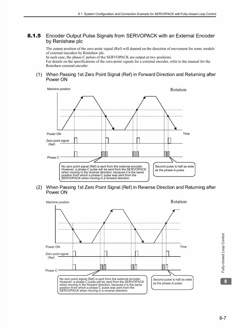
7/17/2019 Manual Yaskawa_servo_drive.pdf
http://slidepdf.com/reader/full/manual-yaskawaservodrivepdf 249/328
8.1 System Configuration and Connection Example for SERVOPACK with Fully-closed Loop Control
8-7
F u l l y - c l o s e d L o o p C o n t r o l
8.1.5 Encoder Output Pulse Signals from SERVOPACK with an External Encoderby Renishaw plc
The output position of the zero point signal (Ref) will depend on the direction of movement for some modelsof external encoders by Renishaw plc.
In such case, the phase-C pulses of the SERVOPACK are output at two positions.For details on the specifications of the zero-point signals for a external encoder, refer to the manual for theRenishaw external encoder.
(1) When Passing 1st Zero Point Signal (Ref) in Forward Direction and Returning afterPower ON
(2) When Passing 1st Zero Point Signal (Ref) in Reverse Direction and Returning afterPower ON
Machine position
Power ON
Zero point signal
Ref
Phase C
Time
Second pulse is half as wide
as the phase-A pulse.
No zero point signal (Ref) is sent from the external encoder.However, a phase-C pulse will be sent from the SERVOPACK
when moving in the reverse direction, because it is the sameposition from which a phase-C pulse was sent from theSERVOPACK when moving in a forward direction.
Rotation
Machine position
Power ON
Zero point signal
Ref
Phase C
Time
Second pulse is half as wide
as the phase-A pulse.
No zero point signal (Ref) is sent from the external encoder.However, a phase-C pulse will be sent from the SERVOPACKwhen moving in the forward direction, because it is the same
position from which a phase-C pulse was sent from theSERVOPACK when moving in a reverse direction.
Rotation
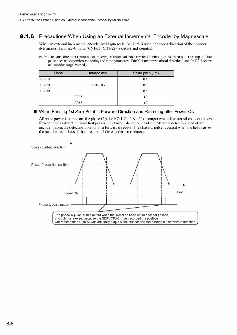
7/17/2019 Manual Yaskawa_servo_drive.pdf
http://slidepdf.com/reader/full/manual-yaskawaservodrivepdf 250/328
8 Fully-closed Loop Control
8.1.6 Precautions When Using an External Incremental Encoder by Magnescale
8-8
8.1.6 Precautions When Using an External Incremental Encoder by Magnescale
When an external incremental encoder by Magnescale Co., Ltd. is used, the count direction of the encoderdetermines if a phase-C pulse (CN1-21, CN1-22) is output and counted.
Note: The count direction (counting up or down) of the encoder determines if a phase-C pulse is output. The output of the pulse does not depend on the settings of these parameters: Pn000.0 (motor rotational direction ) and Pn002.3 (exter-nal encoder usage method).
When Passing 1st Zero Point in Forward Direction and Returning after Power ON
After the power is turned on, the phase-C pulse (CN1-21, CN1-22) is output when the external encoder movesforward and its detection head first passes the phase-C detection position. After the detection head of theencoder passes the detection position in a forward direction, the phase-C pulse is output when the head passesthe position regardless of the direction of the encoder’s movement.
Model Interpolator Scale pitch (µm)
SL710
PL101-RY
800
SL720 800
SL730 800
SR75 80
SR85 80
Scale count-up direction
Phase-C detection position
Power ON Time
Phase-C pulse output
The phase-C pulse is also output when the detection head of the encoder passesthis point in reverse, because the SERVOPACK has recorded the positionwhere the phase-C pulse was originally output when first passing the position in the forward direction.
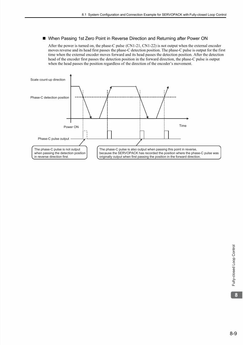
7/17/2019 Manual Yaskawa_servo_drive.pdf
http://slidepdf.com/reader/full/manual-yaskawaservodrivepdf 251/328
8.1 System Configuration and Connection Example for SERVOPACK with Fully-closed Loop Control
8-9
F u l l y - c l o s e d L o o p C o n t r o l
When Passing 1st Zero Point in Reverse Direction and Returning after Power ON
After the power is turned on, the phase-C pulse (CN1-21, CN1-22) is not output when the external encodermoves reverse and its head first passes the phase-C detection position. The phase-C pulse is output for the firsttime when the external encoder moves forward and its head passes the detection position. After the detection
head of the encoder first passes the detection position in the forward direction, the phase-C pulse is outputwhen the head passes the position regardless of the direction of the encoder’s movement.
The phase-C pulse is not outputwhen passing the detection positionin reverse direction first.
The phase-C pulse is also output when passing this point in reverse,because the SERVOPACK has recorded the position where the phase-C pulse wasoriginally output when first passing the position in the forward direction.
Scale count-up direction
Phase-C detection position
Power ON Time
Phase-C pulse output

7/17/2019 Manual Yaskawa_servo_drive.pdf
http://slidepdf.com/reader/full/manual-yaskawaservodrivepdf 252/328
8 Fully-closed Loop Control
8.1.6 Precautions When Using an External Incremental Encoder by Magnescale
8-10
When Using an External Encoder with Multiple Zero Points and Passing 1st Zero Point inForward Direction and Returning after Power ON
When using an external encoder with multiple zero points, the same logic as that explained earlier for anencoder with only one zero point applies to each zero point.
See When Passing 1st Zero Point in Forward Direction and Returning after Power ON .
When Using an External Encoder with Multiple Zero Points and Passing 1st Zero Point inReverse Direction and Returning after Power ON
When using an external encoder with multiple zero points, the same logic as that explained earlier for anencoder with only one zero point applies to each zero point.See When Passing 1st Zero Point in Reverse Direction and Returning after Power ON .
To output the phase-C pulse when a detection point is passed in reverse, set the following parameter to 1.
Even after zero point 1 has first been passedin the forward direction, the phase-C pulse is notoutput here because zero point 2 is passedin reverse direction.
The phase-C pulse is also output when passing this pointin reverse, because the SERVOPACK has recordedthe position where the phase-C pulse was originally outputwhen first passing the position in the forward direction.
Scale count-up direction
Power ON Time
Phase-C pulse output
Zero point 1 Zero point 1 Zero point 2 Zero point 2
Scale count-up direction
Power ON Time
Phase-C pulse output
Zero point 1 Zero point 3Zero point 2ero point
Zero point 2
Phase-C pulse is not output when passinga zero point in reverse direction.
Zero point 3
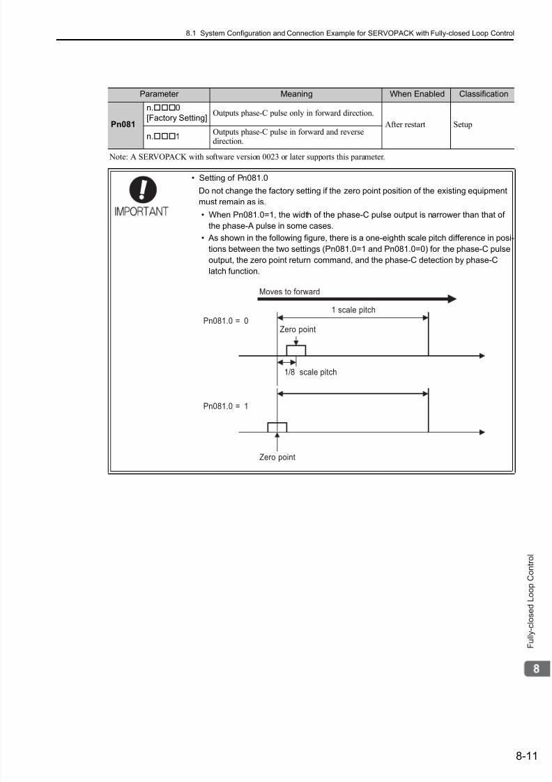
7/17/2019 Manual Yaskawa_servo_drive.pdf
http://slidepdf.com/reader/full/manual-yaskawaservodrivepdf 253/328
8.1 System Configuration and Connection Example for SERVOPACK with Fully-closed Loop Control
8-11
F u l l y - c l o s e d L o o p C o n t r o l
Note: A SERVOPACK with software version 0023 or later supports this parameter.
Parameter Meaning When Enabled Classification
Pn081
n.0
[Factory Setting]Outputs phase-C pulse only in forward direction.
After restart Setup
n.1Outputs phase-C pulse in forward and reversedirection.
• Setting of Pn081.0
Do not change the factory setting if the zero point position of the existing equipment
must remain as is.
• When Pn081.0=1, the width of the phase-C pulse output is narrower than that of
the phase-A pulse in some cases.
• As shown in the following figure, there is a one-eighth scale pitch difference in posi-
tions between the two settings (Pn081.0=1 and Pn081.0=0) for the phase-C pulse
output, the zero point return command, and the phase-C detection by phase-C
latch function.
1/8 scale pitch
Pn081.0 = 0Zero point
Zero point
Moves to forward
1 scale pitch
Pn081.0 = 1

7/17/2019 Manual Yaskawa_servo_drive.pdf
http://slidepdf.com/reader/full/manual-yaskawaservodrivepdf 254/328
8 Fully-closed Loop Control
8-12
8.2 SERVOPACK Startup Procedure
First check that the SERVOPACK operates correctly with semi-closed loop control, then check that it operatescorrectly with fully-closed loop control.The following describes the startup procedure for the SERVOPACK in fully-closed loop control.
Procedure Description OperationParameters Requiring
SettingsController
1
Check operation of the wholesequence in semi-closed loopcontrol and without any load.
Items to Check
• Power supply circuit wiring
• Servomotor wiring
• Encoder wiring
• Wiring of I/O signal lines fromthe host controller
• Servomotor rotation direction,speed, and number of rotations
• Operation of safety mecha-nisms, such as the brakes andthe overtravel mechanism
Set the parameters so that the SER-VOPACK operates correctly insemi-closed loop control (Pn002.3= 0) without any load and checkthe following points.
• Is there an error with the SER-VOPACK?
• Does the JOG operation operatecorrectly when operating theSERVOPACK in standalone
mode?• Do the I/O signals turn ON/OFF
correctly?
• Does the servomotor turn ONafter the servo ON signal has been input?
• Does the servomotor operatecorrectly when the position ref-erence is input by the host con-troller?
• Basic Function Select Switch0 (Pn000)
• Application Function SelectSwitch 1 (Pn001)
• External Encoder Usage(Pn002.3)
• Electronic Gear Ratio(Numerator) (Pn20E)
• Electronic Gear Ratio(Denominator) (Pn210)
• Input Signal Selection(Pn50A, Pn50B, Pn511)
• Output Signal Selection(Pn50E, Pn50F, Pn510)
SERVOPACK or
host controller
2
Check operation of the systemconnected with the machine andservomotor in semi-closed loopcontrol mode.
Items to Check
• Initial responsiveness of thesystem connected with themachine
• Movement direction, distance,and speed of the machine spec-ified by the host controller
Connect the servomotor to themachine.
Set the moment of inertia ratio(Pn103) using the advanced auto-
tuning function.Check that the machine operates inthe correct direction, distance, andspeed as directed by the host con-troller.
• Moment of inertia ratio(Pn103)
Host controller
3
Check the external encoder.
Item to Check
• Are signals from the externalencoder received correctly?
Set parameters related to the fully-closed loop control and move themachine with your hand withoutturning ON the power supply to theservomotor. Check the followingstatus with the digital operator or
SigmaWin+.
• Does the fully-closed feedback pulse counter (Un00E) count upwhen the servomotor moves inthe forward direction?
• Is the distance the machinemoved about visually the sameas the amount counted by thefully-closed feedback pulsecounter (Un00E)?
Note: The unit for fully-closedfeedback pulse counter(Un00E) is one pulse, whichis equivalent to the external
encoder sine wave pitchdivided by the number ofdivisions*.
∗ Refer to 8.3.5 Electronic Gearfor details on the number ofdivisions.
• External Encoder Usage(Pn002.3)
• Number of External ScalePitch (Pn20A)
• Electronic Gear Ratio(Numerator) (Pn20E)
• Electronic Gear Ratio(Denominator) (Pn210)
• Encoder Output Resolution(Pn281)
• Excessive Error LevelBetween Servomotor andLoad Positions (Pn51B)
• Positioning CompletedWidth (Pn522)
• Multiplier per One Fully-closed Rotation (Pn52A)
−
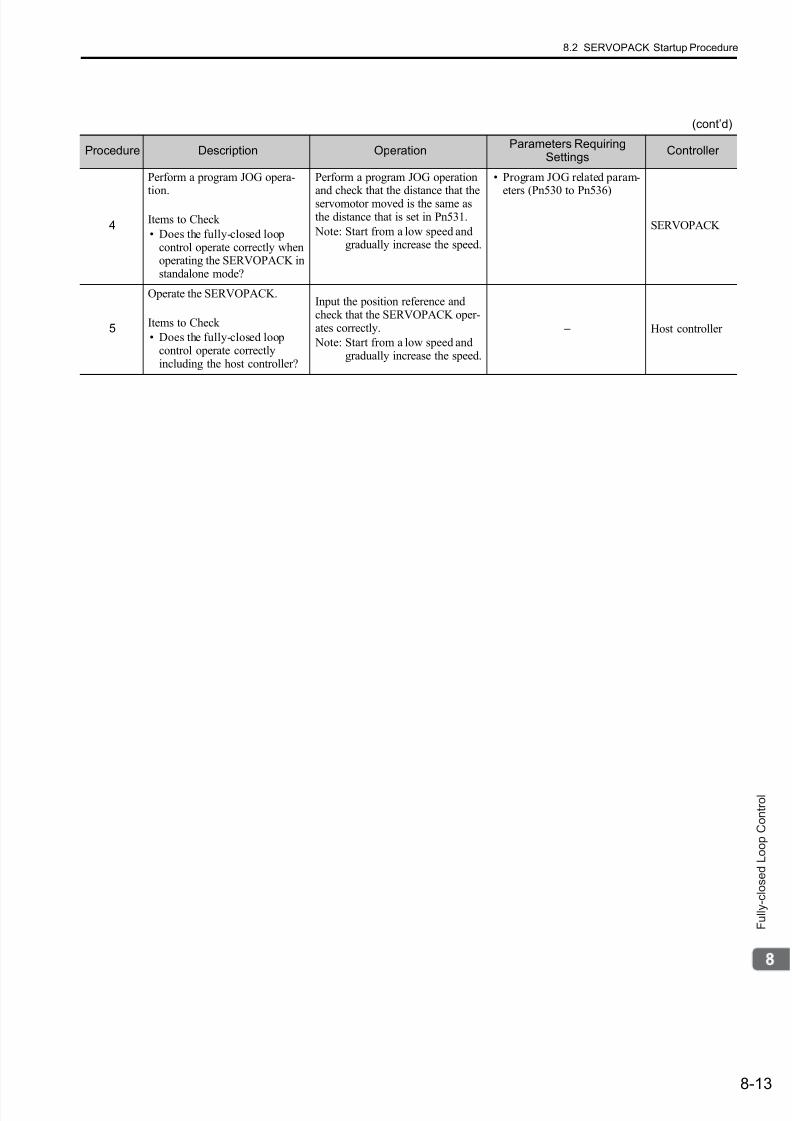
7/17/2019 Manual Yaskawa_servo_drive.pdf
http://slidepdf.com/reader/full/manual-yaskawaservodrivepdf 255/328
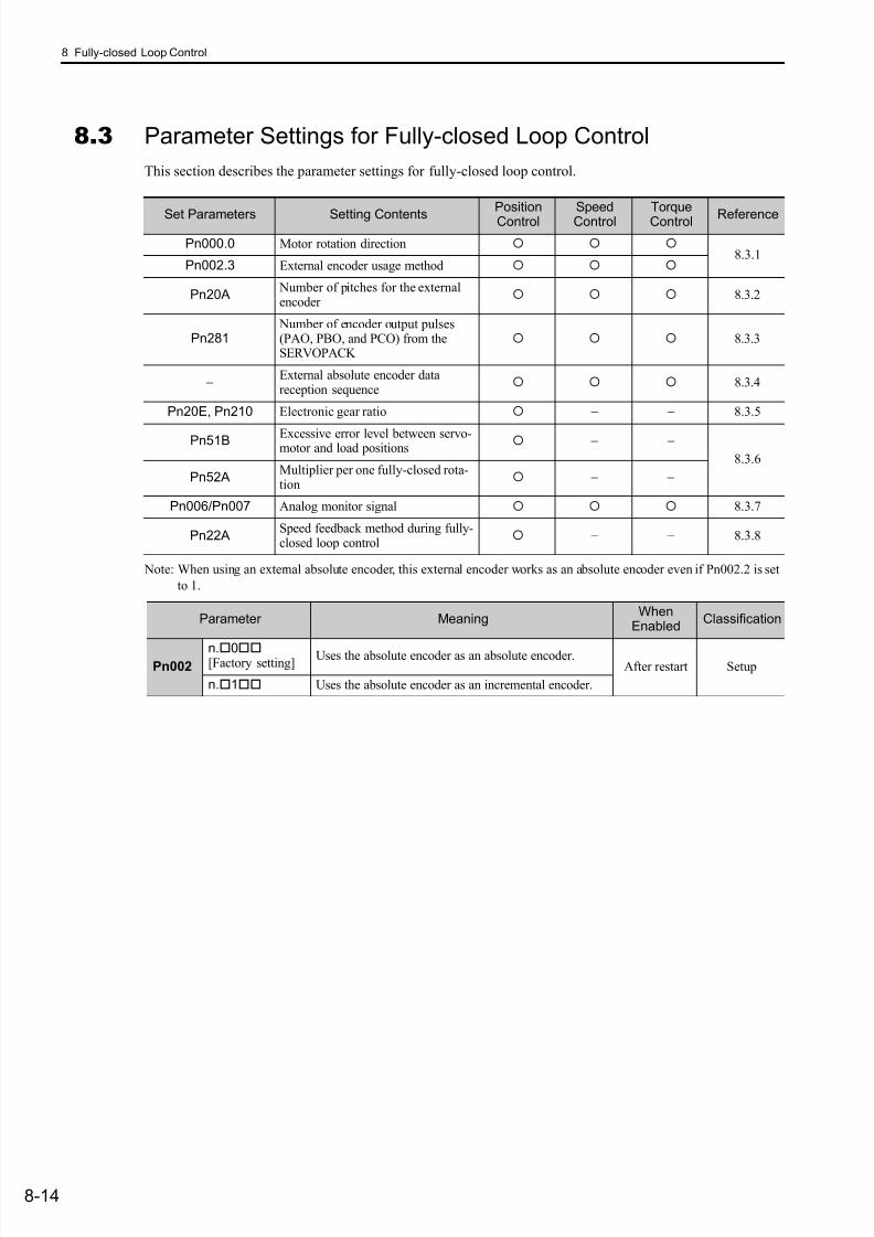
7/17/2019 Manual Yaskawa_servo_drive.pdf
http://slidepdf.com/reader/full/manual-yaskawaservodrivepdf 256/328
8 Fully-closed Loop Control
8-14
8.3 Parameter Settings for Fully-closed Loop Control
This section describes the parameter settings for fully-closed loop control.
Note: When using an external absolute encoder, this external encoder works as an absolute encoder even if Pn002.2 is set
to 1.
Set Parameters Setting ContentsPositionControl
SpeedControl
TorqueControl Reference
Pn000.0 Motor rotation direction 8.3.1
Pn002.3 External encoder usage method
Pn20A Number of pitches for the externalencoder
8.3.2
Pn281 Number of encoder output pulses(PAO, PBO, and PCO) from theSERVOPACK
8.3.3
− External absolute encoder datareception sequence
8.3.4
Pn20E, Pn210 Electronic gear ratio − − 8.3.5
Pn51B Excessive error level between servo-motor and load positions
− −8.3.6
Pn52AMultiplier per one fully-closed rota-tion
− −
Pn006/Pn007 Analog monitor signal 8.3.7
Pn22ASpeed feedback method during fully-closed loop control
− − 8.3.8
Parameter MeaningWhen
EnabledClassification
Pn002n.0[Factory setting]
Uses the absolute encoder as an absolute encoder.After restart Setup
n.1 Uses the absolute encoder as an incremental encoder.

7/17/2019 Manual Yaskawa_servo_drive.pdf
http://slidepdf.com/reader/full/manual-yaskawaservodrivepdf 257/328
8.3 Parameter Settings for Fully-closed Loop Control
8-15
F u l l y - c l o s e d L o o p C o n t r o l
8.3.1 Motor Rotation Direction
The motor rotation direction can be set. To perform fully-closed loop control, it is necessary to set the motorrotation direction with both Pn000.0 (motor rotation direction) and Pn002.3 (external encoder usage).
(1) Setting Parameter Pn000.0The standard setting for forward rotation is counterclockwise (CCW) as viewed from the load end of the ser-
vomotor.
Note: SigmaWin+ trace waveforms are shown in the above table.
(2) Setting Parameter Pn002.3
∗ The mode will be switched to semi-closed position control if Pn002.3 is set to 0.
Parameter Forward/Reverse
ReferenceDirection of Motor Rotation and Encoder Output Pulse
ApplicableOvertravel
(OT)
Pn000
n.
0Sets CCW as forwarddirection.[Factory setting]
ForwardReference
P-OT
ReverseReference
N-OT
n.1Sets CW as forwarddirection.(Reverse RotationMode)
ForwardReference
P-OT
ReverseReference
N-OT
PAO
PBO
+
CCWPhase B
advanced
Time
Encoder output pulse
Motor speedTorque reference
Motor speed
PAO
PBO
+
CW
Phase A
advancedTime
Encoder output pulseMotor speed
Torque reference
Motor speed
PAO
PBO
+
CW Phase Badvanced
Time
Encoder output pulse
Motor speedTorque reference
Motor speed
PAO
PBO
+
CCW
Phase A
advanced
Encoder output pulseMotor speedTorque reference
Motor speed
Time
Parameter Name MeaningWhen
EnabledClassification
Pn002
n.0 [Factory setting]
External EncoderUsage
Do not use external encoder.∗
After restart Setup
n.1 Use in forward rotation with forward reference.
n.2 Reserved parameter (Do not change).
n.3 Use in reversed rotation with forward reference.
n.4 Reserved parameter (Do not change).
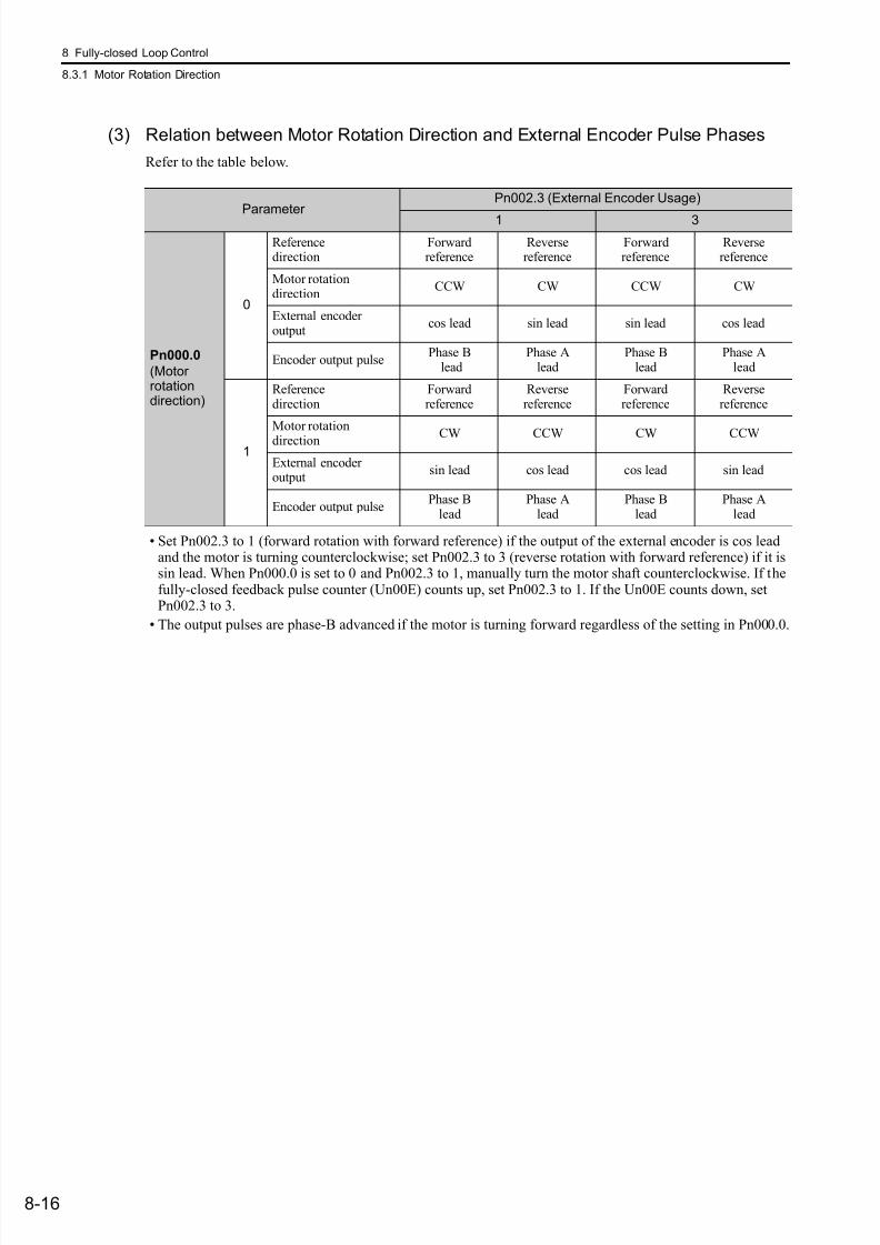
7/17/2019 Manual Yaskawa_servo_drive.pdf
http://slidepdf.com/reader/full/manual-yaskawaservodrivepdf 258/328
8 Fully-closed Loop Control
8.3.1 Motor Rotation Direction
8-16
(3) Relation between Motor Rotation Direction and External Encoder Pulse Phases
Refer to the table below.
• Set Pn002.3 to 1 (forward rotation with forward reference) if the output of the external encoder is cos leadand the motor is turning counterclockwise; set Pn002.3 to 3 (reverse rotation with forward reference) if it issin lead. When Pn000.0 is set to 0 and Pn002.3 to 1, manually turn the motor shaft counterclockwise. If thefully-closed feedback pulse counter (Un00E) counts up, set Pn002.3 to 1. If the Un00E counts down, setPn002.3 to 3.
• The output pulses are phase-B advanced if the motor is turning forward regardless of the setting in Pn000.0.
Parameter Pn002.3 (External Encoder Usage)
1 3
Pn000.0
(Motor rotationdirection)
0
Referencedirection
Forwardreference
Reversereference
Forwardreference
Reversereference
Motor rotationdirection
CCW CW CCW CW
External encoderoutput
cos lead sin lead sin lead cos lead
Encoder output pulsePhase B
leadPhase A
leadPhase B
leadPhase A
lead
1
Referencedirection
Forwardreference
Reversereference
Forwardreference
Reversereference
Motor rotation
direction CW CCW CW CCW
External encoder output
sin lead cos lead cos lead sin lead
Encoder output pulsePhase B
leadPhase A
leadPhase B
leadPhase A
lead
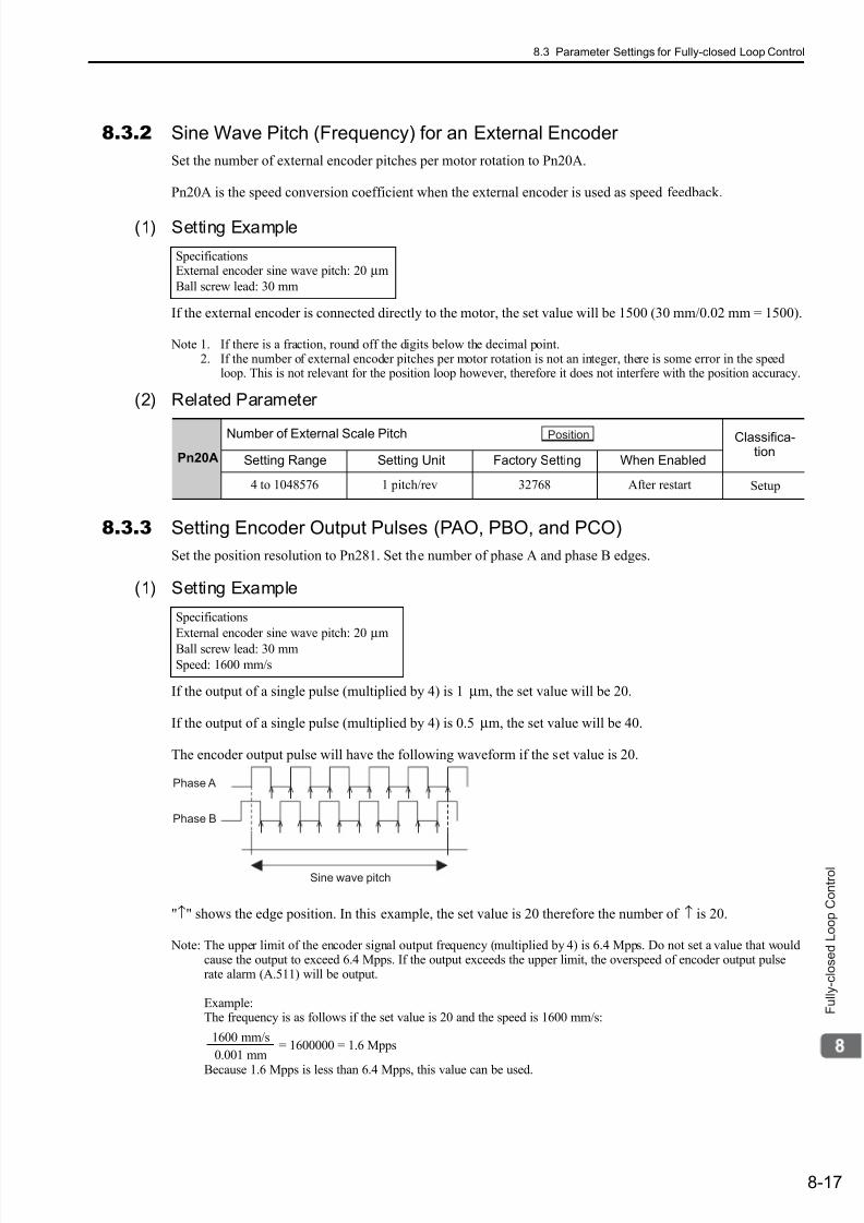
7/17/2019 Manual Yaskawa_servo_drive.pdf
http://slidepdf.com/reader/full/manual-yaskawaservodrivepdf 259/328
8.3 Parameter Settings for Fully-closed Loop Control
8-17
F u l l y - c l o s e d L o o p C o n t r o l
8.3.2 Sine Wave Pitch (Frequency) for an External Encoder
Set the number of external encoder pitches per motor rotation to Pn20A.
Pn20A is the speed conversion coefficient when the external encoder is used as speed feedback.
(1) Setting Example
If the external encoder is connected directly to the motor, the set value will be 1500 (30 mm/0.02 mm = 1500).
Note 1. If there is a fraction, round off the digits below the decimal point.2. If the number of external encoder pitches per motor rotation is not an integer, there is some error in the speed
loop. This is not relevant for the position loop however, therefore it does not interfere with the position accuracy.
(2) Related Parameter
8.3.3 Setting Encoder Output Pulses (PAO, PBO, and PCO)
Set the position resolution to Pn281. Set the number of phase A and phase B edges.
(1) Setting Example
If the output of a single pulse (multiplied by 4) is 1 µm, the set value will be 20.
If the output of a single pulse (multiplied by 4) is 0.5 µm, the set value will be 40.
The encoder output pulse will have the following waveform if the set value is 20.
"↑" shows the edge position. In this example, the set value is 20 therefore the number of ↑ is 20.
Note: The upper limit of the encoder signal output frequency (multiplied by 4) is 6.4 Mpps. Do not set a value that wouldcause the output to exceed 6.4 Mpps. If the output exceeds the upper limit, the overspeed of encoder output pulserate alarm (A.511) will be output.
Example:The frequency is as follows if the set value is 20 and the speed is 1600 mm/s:
= 1600000 = 1.6 Mpps
Because 1.6 Mpps is less than 6.4 Mpps, this value can be used.
SpecificationsExternal encoder sine wave pitch: 20 µm
Ball screw lead: 30 mm
Pn20A
Number of External Scale Pitch Classifica-tion
Setting Range Setting Unit Factory Setting When Enabled
4 to 1048576 1 pitch/rev 32768 After restart Setup
Position
Specifications
External encoder sine wave pitch: 20 µm
Ball screw lead: 30 mm
Speed: 1600 mm/s
Phase A
Phase B
Sine wave pitch
1600 mm/s
0.001 mm
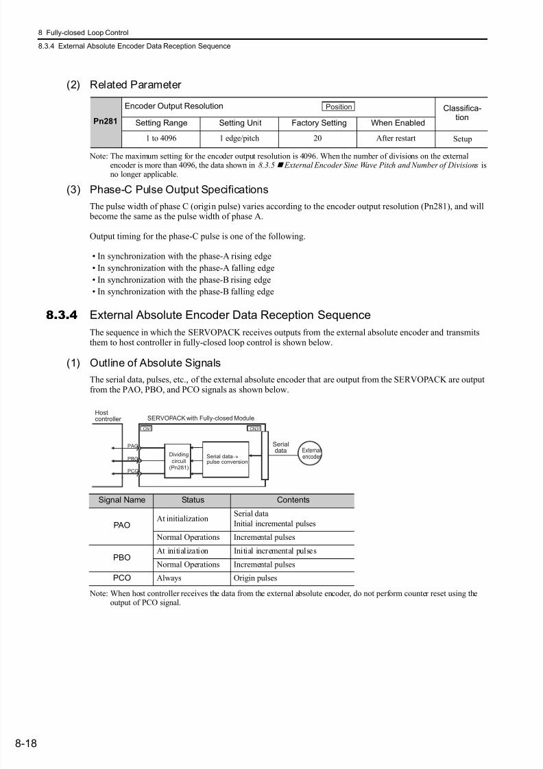
7/17/2019 Manual Yaskawa_servo_drive.pdf
http://slidepdf.com/reader/full/manual-yaskawaservodrivepdf 260/328
8 Fully-closed Loop Control
8.3.4 External Absolute Encoder Data Reception Sequence
8-18
(2) Related Parameter
Note: The maximum setting for the encoder output resolution is 4096. When the number of divisions on the externalencoder is more than 4096, the data shown in 8.3.5 External Encoder Sine Wave Pitch and Number of Divisions isno longer applicable.
(3) Phase-C Pulse Output Specifications
The pulse width of phase C (origin pulse) varies according to the encoder output resolution (Pn281), and will become the same as the pulse width of phase A.
Output timing for the phase-C pulse is one of the following.
• In synchronization with the phase-A rising edge
• In synchronization with the phase-A falling edge• In synchronization with the phase-B rising edge
• In synchronization with the phase-B falling edge
8.3.4 External Absolute Encoder Data Reception Sequence
The sequence in which the SERVOPACK receives outputs from the external absolute encoder and transmitsthem to host controller in fully-closed loop control is shown below.
(1) Outline of Absolute Signals
The serial data, pulses, etc., of the external absolute encoder that are output from the SERVOPACK are outputfrom the PAO, PBO, and PCO signals as shown below.
Note: When host controller receives the data from the external absolute encoder, do not perform counter reset using theoutput of PCO signal.
Pn281
Encoder Output Resolution Classifica-tion
Setting Range Setting Unit Factory Setting When Enabled
1 to 4096 1 edge/pitch 20 After restart Setup
Position
Signal Name Status Contents
PAOAt initialization
Serial data
Initial incremental pulses
Normal Operations Incremental pulses
PBOAt initialization Initial incremental pulses
Normal Operations Incremental pulses
PCO Always Origin pulses
Serialdata External
encoder Serial data→pulse conversion
Hostcontroller SERVOPACK with Fully-closed Module
CN31CN1
PAO
PBO
PCO
Dividing
circuit
(Pn281)
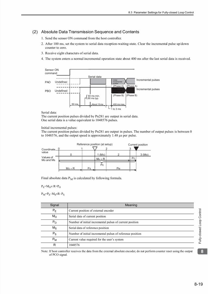
7/17/2019 Manual Yaskawa_servo_drive.pdf
http://slidepdf.com/reader/full/manual-yaskawaservodrivepdf 261/328
8.3 Parameter Settings for Fully-closed Loop Control
8-19
F u l l y - c l o s e d L o o p C o n t r o l
(2) Absolute Data Transmission Sequence and Contents
1. Send the sensor ON command from the host controller.
2. After 100 ms, set the system to serial data reception-waiting-state. Clear the incremental pulse up/downcounter to zero.
3. Receive eight characters of serial data.
4. The system enters a normal incremental operation state about 400 ms after the last serial data is received.
Serial data:The current position pulses divided by Pn281 are output in serial data.One serial data is a value equivalent to 1048576 pulses.
Initial incremental pulses:The current position pulses divided by Pn281 are output in pulses. The number of output pulses is between 0to 1048576, and the output speed is approximately 1.48 µs per pulse.
Final absolute data PM is calculated by following formula.
PE=MO× R+PO
PM=PE –MS×R–PS
Note: If host controller receives the data from the external absolute encoder, do not perform counter reset using the outputof PCO signal.
Sensor ON
command
PAO
PBO
Incremental pulses
Incremental pulsesUndefined
Undefined
(Phase A) (Phase A)
(Phase B) (Phase B)
Serial data
400 ms max.50 ms
1 to 3 ms
About 15 ms
90 ms typ.60 ms min.
Initialincrementalpulses
Initialincrementalpulses
0 1 2 3
3 (Mo)20 1 (MS)
PE
PMPSMS × R
Mo × R PO
Coordinatevalue
Values ofMo and Ms
Reference position (at setup) Current position
Signal MeaningPE Current position of external encoder
MO Serial data of current position
PO Number of initial incremental pulses of current position
MS Serial data of reference position
PS Number of initial incremental pulses of reference position
PM Current value required for the user’s system
R 1048576
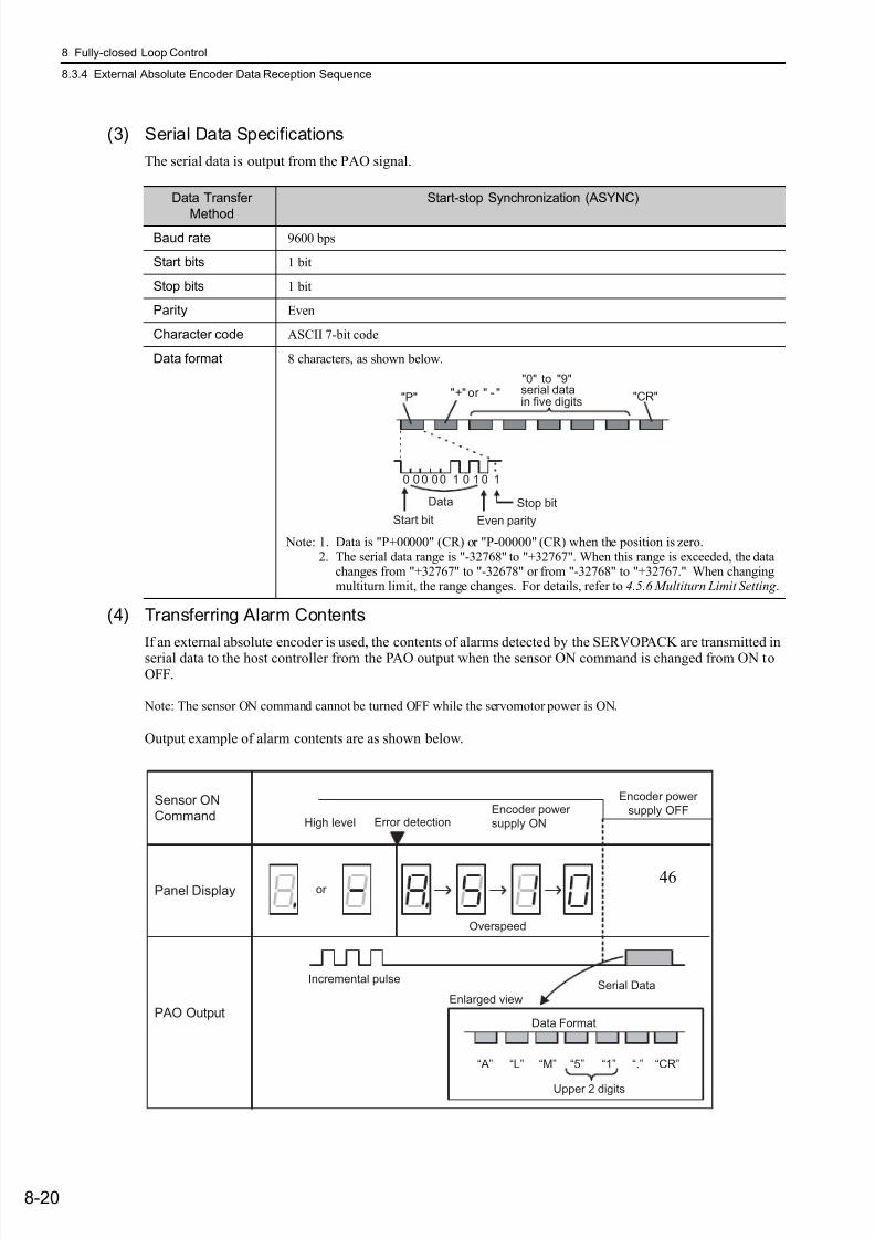
7/17/2019 Manual Yaskawa_servo_drive.pdf
http://slidepdf.com/reader/full/manual-yaskawaservodrivepdf 262/328
8 Fully-closed Loop Control
8.3.4 External Absolute Encoder Data Reception Sequence
8-20
(3) Serial Data Specifications
The serial data is output from the PAO signal.
(4) Transferring Alarm Contents
If an external absolute encoder is used, the contents of alarms detected by the SERVOPACK are transmitted inserial data to the host controller from the PAO output when the sensor ON command is changed from ON toOFF.
Note: The sensor ON command cannot be turned OFF while the servomotor power is ON.
Output example of alarm contents are as shown below.
Data Transfer
Method
Start-stop Synchronization (ASYNC)
Baud rate 9600 bps
Start bits 1 bit
Stop bits 1 bit
Parity Even
Character code ASCII 7-bit code
Data format 8 characters, as shown below.
Note: 1. Data is "P+00000" (CR) or "P-00000" (CR) when the position is zero.2. The serial data range is "-32768" to "+32767". When this range is exceeded, the data
changes from "+32767" to "-32678" or from "-32768" to "+32767." When changingmultiturn limit, the range changes. For details, refer to 4.5.6 Multiturn Limit Setting .
Data
Start bit Even parity
serial datain five digits
"+" or " - ""0" to "9"
"CR""P"
Stop bit
0 0 0 00 1 0 1 0 1
“A” “L” “M” “5” “1” “.” “CR”
Encoder power
supply OFFHigh level
Encoder power
supply ON
Incremental pulseSerial Data
Enlarged view
Sensor ON
Command
Panel Display
PAO OutputData Format
Upper 2 digits
Error detection
or
Overspeed
46

7/17/2019 Manual Yaskawa_servo_drive.pdf
http://slidepdf.com/reader/full/manual-yaskawaservodrivepdf 263/328
8.3 Parameter Settings for Fully-closed Loop Control
8-21
F u l l y - c l o s e d L o o p C o n t r o l
8.3.5 Electronic Gear
Refer to 4.2.4 Electronic Gear for the purpose of setting the electronic gear.The following formula is used to calculate the electronic gear ratio in fully-closed loop control.
Note: Set Pn20E (numerator B) and Pn210 (denominator A) to integral values.
The setting range is defined by 0.001 ≤ ≤ 4000.
The following table shows the various external encoder sin wave pitches and the number of divisions.
External Encoder Sine Wave Pitch and Number of Divisions
Calculate the electronic gear ratio with the values in the following table.
∗1. Models for serial converter units.∗2. When using the encoder pulse output with these external encoders, the setting range of Pn281 is restricted. For
details, refer to 8.3.3 Setting Encoder Output Pulses (PAO, PBO, and PCO).∗3. Model for sensor head with interpolator.
∗4. Model for interface unit by Heidenhain.∗5. For details on this external encoder, contact Mitutoyo.∗6. Model for rotational external encoder.
Refer to the manuals for the external encoder and serial converter unit for details on the sine wave pitch andthe number of divisions of the external encoder.
A
B
Pn210
Pn20E
External encoder sine wave pitch
Travel distance per position reference (reference unit) × Number of divisionsElectronic gear ratio == =
46 and 64
B
A
Type ofExternal
Encoder
Manufacturer External Encoder
ModelSine WavePitch [µm]
Model of RelayDevice between
SERVOPACK andExternal Encoder
Numberof
Divisions
Resolution
Incremental
Heidenhain
LIDA48 20 JZDP-D003--E∗1 256 0.078 µm
LIDA18 40 JZDP-D003--E∗1 256 0.156 µm
LIF48 4 JZDP-D003--E∗1 256 0.016 µm
Renishaw plc RGH22B 20 JZDP-D005--E∗1 256 0.078 µm
Magnescale Co., Ltd.
SR75-LF*2 80 – 8192 0.0098 µm
SR75-MF 80 – 1024 0.078 µm
SR85-LF*2 80 – 8192 0.0098 µm
SR85-MF 80 – 1024 0.078 µm
SL700*2,SL710*2
,
SL720*2,SL730*2
800 PL101-RY*3 8192 0.0977 µm
Absolute
Heidenhain LIC4100 20.48 EIB3391Y*4 4096 0.005 µm
Mitutoyo Corporation
ST781A/ST781AL 256 – 512 0.5 µm
ST782A/ST782AL 256 – 512 0.5 µm
ST783/ST783AL 51.2 – 512 0.1 µm
ST784/ST784AL 51.2 – 512 0.1 µm
ST788A/ST788AL 51.2 – 512 0.1 µm
ST789A/ST789AL*5 25.6 – 512 0.05 µm
Magnescale Co., Ltd.
SR77-LF*2
80 – 8192 0.0098 µmSR77-MF 80 – 1024 0.078 µm
SR87-LF*2 80 – 8192 0.0098 µm
SR87-MF 80 – 1024 0.078 µm
RU77-4096ADF*6 – – 256 20 bits
RU77-4096AFFT01*6 – – 1024 22 bits
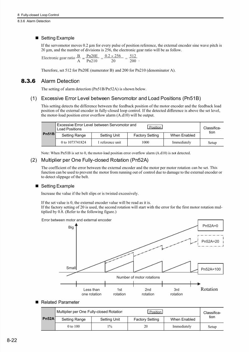
7/17/2019 Manual Yaskawa_servo_drive.pdf
http://slidepdf.com/reader/full/manual-yaskawaservodrivepdf 264/328
8 Fully-closed Loop Control
8.3.6 Alarm Detection
8-22
Setting Example
If the servomotor moves 0.2 µm for every pulse of position reference, the external encoder sine wave pitch is20 µm, and the number of divisions is 256, the electronic gear ratio will be as follow.
.
Therefore, set 512 for Pn20E (numerator B) and 200 for Pn210 (denominator A).
8.3.6 Alarm Detection
The setting of alarm detection (Pn51B/Pn52A) is shown below.
(1) Excessive Error Level between Servomotor and Load Positions (Pn51B)
This setting detects the difference between the feedback position of the motor encoder and the feedback load position of the external encoder in fully-closed loop control. If the detected difference is above the set level,the motor-load position error overflow alarm (A.d10) will be output.
Note: When Pn51B is set to 0, the motor-load position error overflow alarm (A.d10) is not detected.
(2) Multiplier per One Fully-closed Rotation (Pn52A)
The coefficient of the error between the external encoder and the motor per motor rotation can be set. Thisfunction can be used to prevent the motor from running out of control due to damage to the external encoder orto detect slippage of the belt.
Setting Example
Increase the value if the belt slips or is twisted excessively.
If the set value is 0, the external encoder value will be read as it is.If the factory setting of 20 is used, the second rotation will start with the error for the first motor rotation mul-tiplied by 0.8. (Refer to the following figure.)
Related Parameter
A
B
Pn210
Pn20E
20
0.2 × 256
200
512== = =Electronic gear ratio
Pn51B
Excessive Error Level between Servomotor andLoad Positions Classifica-
tionSetting Range Setting Unit Factory Setting When Enabled
0 to 1073741824 1 reference unit 1000 Immediately Setup
Position
Pn52A=0
Pn52A=100
Pn52A=20
1st
rotation
2nd
rotation
Number of motor rotations
Error between motor and external encoder
3rd
rotation
Less than
one rotation
Small
Big
Rotation
Pn52A
Multiplier per One Fully-closed Rotation Classifica-tion
Setting Range Setting Unit Factory Setting When Enabled
0 to 100 1% 20 Immediately Setup
Position
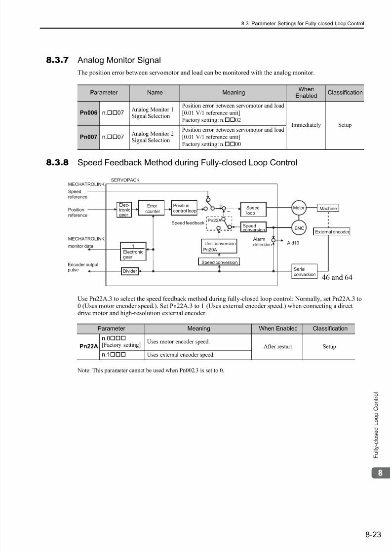
7/17/2019 Manual Yaskawa_servo_drive.pdf
http://slidepdf.com/reader/full/manual-yaskawaservodrivepdf 265/328
8.3 Parameter Settings for Fully-closed Loop Control
8-23
F u l l y - c l o s e d L o o p C o n t r o l
8.3.7 Analog Monitor Signal
The position error between servomotor and load can be monitored with the analog monitor.
8.3.8 Speed Feedback Method during Fully-closed Loop Control
Use Pn22A.3 to select the speed feedback method during fully-closed loop control: Normally, set Pn22A.3 to0 (Uses motor encoder speed.). Set Pn22A.3 to 1 (Uses external encoder speed.) when connecting a directdrive motor and high-resolution external encoder.
Note: This parameter cannot be used when Pn002.3 is set to 0.
Parameter Name MeaningWhen
EnabledClassification
Pn006 n.07Analog Monitor 1Signal Selection
Position error between servomotor and load
[0.01 V/1 reference unit]
Factory setting: n.02Immediately Setup
Pn007 n.07Analog Monitor 2Signal Selection
Position error between servomotor and load
[0.01 V/1 reference unit]
Factory setting: n.00
Parameter Meaning When Enabled Classification
Pn22A
n.0[Factory setting]
Uses motor encoder speed.After restart Setup
n.1 Uses external encoder speed.
Position
reference
MECHATROLINK
Speedreference
ENC
A.d10
Pn22A
MECHATROLINK
1monitor data
Speed conversion
Unit conversion
Pn20A
Elec-tronicgear
Electronicgear
Encoder outputpulse
Error
counter Speedloop
Alarm
detection
Divider
MachinePositioncontrol loop
Serialconversion
Motor
External encoder
Speedconversion
Speed feedback
SERVOPACK
46 and 64
7/17/2019 Manual Yaskawa_servo_drive.pdf
http://slidepdf.com/reader/full/manual-yaskawaservodrivepdf 266/3289-1
T r o u b l e s h o o t i n g
9
Troubleshooting
9.1 Troubleshooting . . . . . . . . . . . . . . . . . . . . . . . . . . . . . . . . . . . . . . . . . . . . . 9-2
9.1.1 List of Alarms . . . . . . . . . . . . . . . . . . . . . . . . . . . . . . . . . . . . . . . . . . . . . . . . . . . . . . . . 9-2
9.1.2 Troubleshooting of Alarms . . . . . . . . . . . . . . . . . . . . . . . . . . . . . . . . . . . . . . . . . . . . . . 9-6
9.2 Warning Displays . . . . . . . . . . . . . . . . . . . . . . . . . . . . . . . . . . . . . . . . . . . 9-22
9.2.1 List of Warnings . . . . . . . . . . . . . . . . . . . . . . . . . . . . . . . . . . . . . . . . . . . . . . . . . . . . . 9-22
9.2.2 Troubleshooting of Warnings . . . . . . . . . . . . . . . . . . . . . . . . . . . . . . . . . . . . . . . . . . . 9-24
9.3 Troubleshooting Malfunction Based on Operation
and Conditions of the Servomotor . . . . . . . . . . . . . . . . . . . . . . . . . . . . .9-28
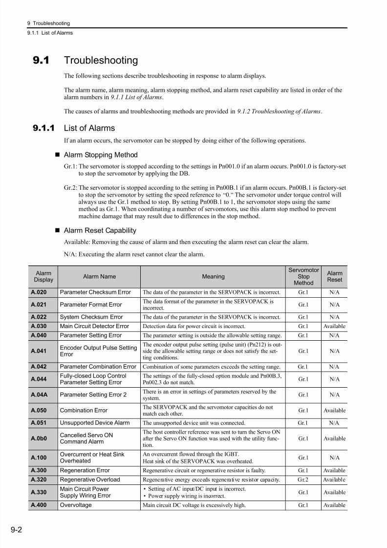
7/17/2019 Manual Yaskawa_servo_drive.pdf
http://slidepdf.com/reader/full/manual-yaskawaservodrivepdf 267/328
9 Troubleshooting
9.1.1 List of Alarms
9-2
9.1 Troubleshooting
The following sections describe troubleshooting in response to alarm displays.
The alarm name, alarm meaning, alarm stopping method, and alarm reset capability are listed in order of the
alarm numbers in 9.1.1 List of Alarms.
The causes of alarms and troubleshooting methods are provided in 9.1.2 Troubleshooting of Alarms.
9.1.1 List of Alarms
If an alarm occurs, the servomotor can be stopped by doing either of the following operations.
Alarm Stopping Method
Gr.1: The servomotor is stopped according to the settings in Pn001.0 if an alarm occurs. Pn001.0 is factory-setto stop the servomotor by applying the DB.
Gr.2: The servomotor is stopped according to the setting in Pn00B.1 if an alarm occurs. Pn00B.1 is factory-setto stop the servomotor by setting the speed reference to “0.” The servomotor under torque control willalways use the Gr.1 method to stop. By setting Pn00B.1 to 1, the servomotor stops using the samemethod as Gr.1. When coordinating a number of servomotors, use this alarm stop method to preventmachine damage that may result due to differences in the stop method.
Alarm Reset Capability
Available: Removing the cause of alarm and then executing the alarm reset can clear the alarm.
N/A: Executing the alarm reset cannot clear the alarm.
AlarmDisplay
Alarm Name MeaningServomotor
StopMethod
AlarmReset
A.020 Parameter Checksum Error The data of the parameter in the SERVOPACK is incorrect. Gr.1 N/A
A.021 Parameter Format Error The data format of the parameter in the SERVOPACK isincorrect.
Gr.1 N/A
A.022 System Checksum Error The data of the parameter in the SERVOPACK is incorrect. Gr.1 N/A
A.030 Main Circuit Detector Error Detection data for power circuit is incorrect. Gr.1 Available
A.040 Parameter Setting Error The parameter setting is outside the allowable setting range. Gr.1 N/A
A.041Encoder Output Pulse SettingError
The encoder output pulse setting (pulse unit) (Pn212) is out-side the allowable setting range or does not satisfy the set-ting conditions.
Gr.1 N/A
A.042 Parameter Combination Error Combination of some parameters exceeds the setting range. Gr.1 N/A
A.044Fully-closed Loop Control
Parameter Setting Error
The settings of the fully-closed option module and Pn00B.3,
Pn002.3 do not match.
Gr.1 N/A
A.04A Parameter Setting Error 2There is an error in settings of parameters reserved by thesystem.
Gr.1 N/A
A.050 Combination Error The SERVOPACK and the servomotor capacities do notmatch each other.
Gr.1 Available
A.051 Unsupported Device Alarm The unsupported device unit was connected. Gr.1 N/A
A.0b0Cancelled Servo ONCommand Alarm
The host controller reference was sent to turn the Servo ONafter the Servo ON function was used with the utility func-tion.
Gr.1 Available
A.100Overcurrent or Heat SinkOverheated
An overcurrent flowed through the IGBT.
Heat sink of the SERVOPACK was overheated.Gr.1 N/A
A.300 Regeneration Error Regenerative circuit or regenerative resistor is faulty. Gr.1 Available
A.320 Regenerative Overload Regenerative energy exceeds regenerative resistor capacity. Gr.2 Available
A.330Main Circuit PowerSupply Wiring Error
• Setting of AC input/DC input is incorrect.
• Power supply wiring is incorrect.Gr.1 Available
A.400 Overvoltage Main circuit DC voltage is excessively high. Gr.1 Available
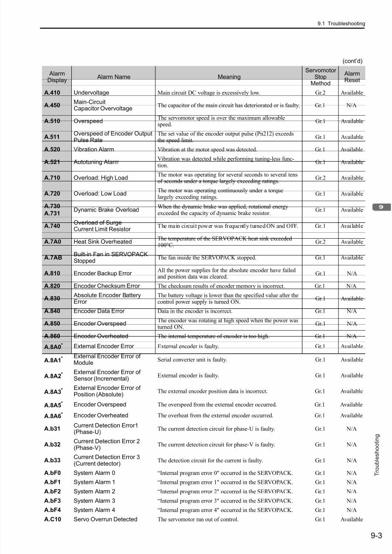
7/17/2019 Manual Yaskawa_servo_drive.pdf
http://slidepdf.com/reader/full/manual-yaskawaservodrivepdf 268/328
9.1 Troubleshooting
9-3
T r o u b l e s h o o t i n g
A.410 Undervoltage Main circuit DC voltage is excessively low. Gr.2 Available
A.450Main-CircuitCapacitor Overvoltage
The capacitor of the main circuit has deteriorated or is faulty. Gr.1 N/A
A.510 OverspeedThe servomotor speed is over the maximum allowablespeed.
Gr.1 Available
A.511Overspeed of Encoder OutputPulse Rate
The set value of the encoder output pulse (Pn212) exceedsthe speed limit.
Gr.1 Available
A.520 Vibration Alarm Vibration at the motor speed was detected. Gr.1 Available
A.521 Autotuning AlarmVibration was detected while performing tuning-less func-tion.
Gr.1 Available
A.710 Overload: High LoadThe motor was operating for several seconds to several tensof seconds under a torque largely exceeding ratings.
Gr.2 Available
A.720 Overload: Low LoadThe motor was operating continuously under a torquelargely exceeding ratings. Gr.1 Available
A.730
A.731Dynamic Brake Overload
When the dynamic brake was applied, rotational energyexceeded the capacity of dynamic brake resistor.
Gr.1 Available
A.740Overload of SurgeCurrent Limit Resistor
The main circuit power was frequently turned ON and OFF. Gr.1 Available
A.7A0 Heat Sink OverheatedThe temperature of the SERVOPACK heat sink exceeded100°C.
Gr.2 Available
A.7ABBuilt-in Fan in SERVOPACKStopped
The fan inside the SERVOPACK stopped. Gr.1 Available
A.810 Encoder Backup Error All the power supplies for the absolute encoder have failedand position data was cleared.
Gr.1 N/A
A.820 Encoder Checksum Error The checksum results of encoder memory is incorrect. Gr.1 N/A
A.830 Absolute Encoder BatteryError
The battery voltage is lower than the specified value after thecontrol power supply is turned ON.
Gr.1 Available
A.840 Encoder Data Error Data in the encoder is incorrect. Gr.1 N/A
A.850 Encoder OverspeedThe encoder was rotating at high speed when the power wasturned ON.
Gr.1 N/A
A.860 Encoder Overheated The internal temperature of encoder is too high. Gr.1 N/A
A.8A0* External Encoder Error External encoder is faulty. Gr.1 Available
A.8A1* External Encoder Error ofModule
Serial converter unit is faulty. Gr.1 Available
A.8A2* External Encoder Error ofSensor (Incremental)
External encoder is faulty. Gr.1 Available
A.8A3* External Encoder Error ofPosition (Absolute)
The external encoder position data is incorrect. Gr.1 Available
A.8A5* Encoder Overspeed The overspeed from the external encoder occurred. Gr.1 Available
A.8A6* Encoder Overheated The overheat from the external encoder occurred. Gr.1 Available
A.b31Current Detection Error1(Phase-U)
The current detection circuit for phase-U is faulty. Gr.1 N/A
A.b32Current Detection Error 2(Phase-V)
The current detection circuit for phase-V is faulty. Gr.1 N/A
A.b33Current Detection Error 3(Current detector)
The detection circuit for the current is faulty. Gr.1 N/A
A.bF0 System Alarm 0 “Internal program error 0" occurred in the SERVOPACK. Gr.1 N/A
A.bF1 System Alarm 1 “Internal program error 1" occurred in the SERVOPACK. Gr.1 N/A
A.bF2 System Alarm 2 “Internal program error 2" occurred in the SERVOPACK. Gr.1 N/A
A.bF3 System Alarm 3 “Internal program error 3" occurred in the SERVOPACK. Gr.1 N/A
A.bF4 System Alarm 4 “Internal program error 4" occurred in the SERVOPACK. Gr.1 N/A
A.C10 Servo Overrun Detected The servomotor ran out of control. Gr.1 Available
(cont’d)
AlarmDisplay
Alarm Name MeaningServomotor
StopMethod
AlarmReset
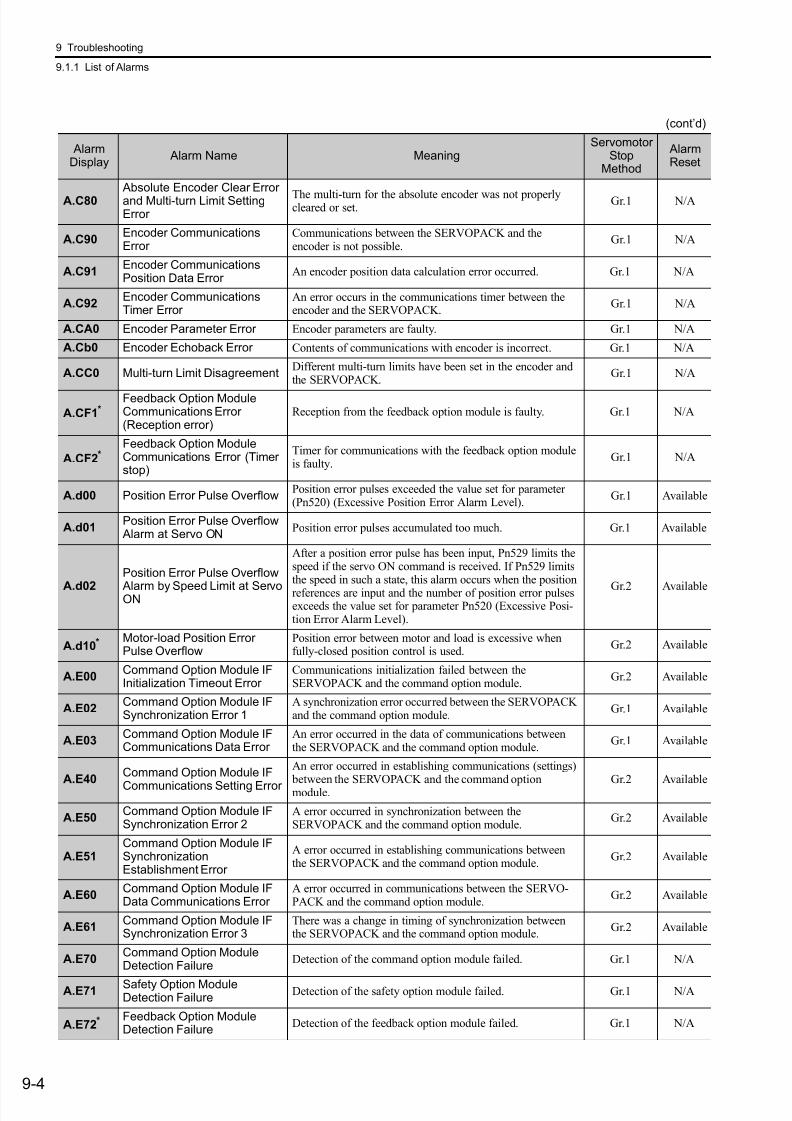
7/17/2019 Manual Yaskawa_servo_drive.pdf
http://slidepdf.com/reader/full/manual-yaskawaservodrivepdf 269/328
9 Troubleshooting
9.1.1 List of Alarms
9-4
A.C80 Absolute Encoder Clear Errorand Multi-turn Limit SettingError
The multi-turn for the absolute encoder was not properlycleared or set.
Gr.1 N/A
A.C90Encoder CommunicationsError
Communications between the SERVOPACK and theencoder is not possible.
Gr.1 N/A
A.C91Encoder CommunicationsPosition Data Error
An encoder position data calculation error occurred. Gr.1 N/A
A.C92Encoder CommunicationsTimer Error
An error occurs in the communications timer between theencoder and the SERVOPACK.
Gr.1 N/A
A.CA0 Encoder Parameter Error Encoder parameters are faulty. Gr.1 N/A
A.Cb0 Encoder Echoback Error Contents of communications with encoder is incorrect. Gr.1 N/A
A.CC0 Multi-turn Limit DisagreementDifferent multi-turn limits have been set in the encoder andthe SERVOPACK.
Gr.1 N/A
A.CF1*Feedback Option ModuleCommunications Error(Reception error)
Reception from the feedback option module is faulty. Gr.1 N/A
A.CF2*Feedback Option ModuleCommunications Error (Timerstop)
Timer for communications with the feedback option moduleis faulty.
Gr.1 N/A
A.d00 Position Error Pulse OverflowPosition error pulses exceeded the value set for parameter(Pn520) (Excessive Position Error Alarm Level).
Gr.1 Available
A.d01Position Error Pulse Overflow Alarm at Servo ON
Position error pulses accumulated too much. Gr.1 Available
A.d02
Position Error Pulse Overflow
Alarm by Speed Limit at ServoON
After a position error pulse has been input, Pn529 limits thespeed if the servo ON command is received. If Pn529 limitsthe speed in such a state, this alarm occurs when the position
references are input and the number of position error pulsesexceeds the value set for parameter Pn520 (Excessive Posi-tion Error Alarm Level).
Gr.2 Available
A.d10* Motor-load Position ErrorPulse Overflow
Position error between motor and load is excessive whenfully-closed position control is used.
Gr.2 Available
A.E00Command Option Module IFInitialization Timeout Error
Communications initialization failed between theSERVOPACK and the command option module.
Gr.2 Available
A.E02Command Option Module IFSynchronization Error 1
A synchronization error occurred between the SERVOPACKand the command option module.
Gr.1 Available
A.E03Command Option Module IFCommunications Data Error
An error occurred in the data of communications betweenthe SERVOPACK and the command option module.
Gr.1 Available
A.E40Command Option Module IF
Communications Setting Error
An error occurred in establishing communications (settings) between the SERVOPACK and the command optionmodule.
Gr.2 Available
A.E50Command Option Module IFSynchronization Error 2
A error occurred in synchronization between theSERVOPACK and the command option module.
Gr.2 Available
A.E51Command Option Module IFSynchronizationEstablishment Error
A error occurred in establishing communications betweenthe SERVOPACK and the command option module.
Gr.2 Available
A.E60Command Option Module IFData Communications Error
A error occurred in communications between the SERVO-PACK and the command option module.
Gr.2 Available
A.E61Command Option Module IFSynchronization Error 3
There was a change in timing of synchronization betweenthe SERVOPACK and the command option module.
Gr.2 Available
A.E70Command Option ModuleDetection Failure
Detection of the command option module failed. Gr.1 N/A
A.E71 Safety Option ModuleDetection Failure
Detection of the safety option module failed. Gr.1 N/A
A.E72* Feedback Option ModuleDetection Failure
Detection of the feedback option module failed. Gr.1 N/A
(cont’d)
AlarmDisplay
Alarm Name MeaningServomotor
StopMethod
AlarmReset
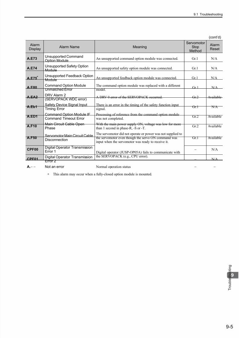
7/17/2019 Manual Yaskawa_servo_drive.pdf
http://slidepdf.com/reader/full/manual-yaskawaservodrivepdf 270/328
9.1 Troubleshooting
9-5
T r o u b l e s h o o t i n g
∗ This alarm may occur when a fully-closed option module is mounted.
A.E73
Unsupported CommandOption Module An unsupported command option module was connected. Gr.1 N/A
A.E74Unsupported Safety OptionModule
An unsupported safety option module was connected. Gr.1 N/A
A.E75* Unsupported Feedback Option
ModuleAn unsupported feedback option module was connected. Gr.1 N/A
A.E80Command Option ModuleUnmatched Error
The command option module was replaced with a differentmodel.
Gr.1 N/A
A.EA2DRV Alarm 2(SERVOPACK WDC error)
A DRV 0 error of the SERVOPACK occurred. Gr.2 Available
A.Eb1Safety Device Signal InputTiming Error
There is an error in the timing of the safety function inputsignal.
Gr.1 N/A
A.ED1Command Option Module IF
Command Timeout Error
Processing of reference from the command option module
was not completed.Gr.2 Available
A.F10Main Circuit Cable OpenPhase
With the main power supply ON, voltage was low for morethan 1 second in phase-R, -S or -T.
Gr.2 Available
A.F50Servomotor Main Circuit CableDisconnection
The servomotor did not operate or power was not supplied tothe servomotor even though the servo ON command wasinput when the servomotor was ready to receive it.
Gr.1 Available
CPF00Digital Operator TransmissionError 1 Digital operator (JUSP-OP05A) fails to communicate with
the SERVOPACK (e.g., CPU error).
− N/A
CPF01Digital Operator TransmissionError 2
− N/A
A.− − Not an error Normal operation status − −
(cont’d)
AlarmDisplay
Alarm Name MeaningServomotor
StopMethod
AlarmReset

7/17/2019 Manual Yaskawa_servo_drive.pdf
http://slidepdf.com/reader/full/manual-yaskawaservodrivepdf 271/328
9 Troubleshooting
9.1.2 Troubleshooting of Alarms
9-6
9.1.2 Troubleshooting of Alarms
When an error occurs in SERVOPACKs, an alarm is displayed such as A. and CPF on the paneloperator. Refer to the following table to identify the cause of an alarm and the action to be taken.
Contact your Yaskawa representative if the problem cannot be solved by the described corrective action.
Alarm: Alarm Name
Cause Investigative Actions Corrective Actions
A.020:
Parameter ChecksumError
(The parameter data inthe SERVOPACK isincorrect.)
The power supply voltage sud-denly dropped.
Measure the power supply voltage.Set the power supply voltage withinthe specified range, and initializethe parameter (Fn005).
The power supply went OFFwhile changing a parameter set-ting.
Note the circumstances when the power supply went OFF.
Initialize the parameter (Fn005) andthen set the parameter again.
The number of times that parame-ters were written exceeded the
limit.
Were the parameters frequentlychanged through the host control-
ler?
The SERVOPACK may be faulty.Repair or replace the SERVO-PACK.
Reconsider the method of writing parameters.
Malfunction caused by noisefrom the AC power supply orgrounding line, static electricitynoise, etc.
Turn the power supply ON and OFFseveral times. If the alarm stilloccurs, there may be noise interfer-ence.
Take countermeasures againstnoise.
Gas, water drops, or cutting oilentered the SERVOPACK andcaused failure of the internalcomponents.
Check the installation conditions.The SERVOPACK may be faulty.Replace the SERVOPACK.
A SERVOPACK fault occurred.Turn the power supply ON and OFFseveral times. If the alarm stilloccurs, the SERVOPACK is faulty.
The SERVOPACK may be faulty.Replace the SERVOPACK.
A.021:
Parameter FormatError
(The parameter data for-mat in the SERVOPACKis incorrect.)
The software version of SERVO-PACK that caused the alarm isolder than that of the written parameter.
Check Fn012 to see if the set soft-ware version agrees with that of theSERVOPACK. If not, an alarm mayoccur.
Write the parameter of anotherSERVOPACK of the same modelwith the same software version.Then turn the power OFF and thenON again.
A SERVOPACK fault occurred. −The SERVOPACK may be faulty.Replace the SERVOPACK.
A.022:
System ChecksumError
(The parameter data inthe SERVOPACK isincorrect.)
The power supply voltage sud-denly dropped.
Measure the power supply voltage.The SERVOPACK may be faulty.Replace the SERVOPACK.
The power supply went OFFwhile setting an utility function.
Note the circumstances when the power supply went OFF.
The SERVOPACK may be faulty.Replace the SERVOPACK.
A SERVOPACK fault occurred.Turn the power supply ON and OFFseveral times. If the alarm still
occurs, the SERVOPACK is faulty.
The SERVOPACK may be faulty.Replace the SERVOPACK.
A.030:
Main Circuit DetectorError
A SERVOPACK fault occurred. − The SERVOPACK may be faulty.Replace the SERVOPACK.
A.040:
Parameter SettingError
(The parameter settingwas out of the allowablesetting range.)
The SERVOPACK and servomo-tor capacities do not match eachother.
Check the combination of SERVO-PACK and servomotor capacities.
Select the proper combination ofSERVOPACK and servomotorcapacities.
A SERVOPACK fault occurred. − The SERVOPACK may be faulty.Replace the SERVOPACK.
The parameter setting is out ofthe specified range.
Check the setting ranges of the parameters that have been changed.
Set the parameter to a value withinthe specified range.
The electronics gear ratio is out
of the setting range.
Check the electronic gear ratio. The
ratio must satisfy:0.001< (Pn20E/Pn210) <4000.
Set the electronic gear ratio in the
range: 0.001< (Pn20E/Pn210)<4000.
A.041:
Encoder Output PulseSetting Error
The encoder output pulse (Pn212)is out of the setting range anddoes not satisfy the setting condi-tions.
Check the parameter Pn212. Set Pn212 to a correct value.

7/17/2019 Manual Yaskawa_servo_drive.pdf
http://slidepdf.com/reader/full/manual-yaskawaservodrivepdf 272/328
9.1 Troubleshooting
9-7
T r o u b l e s h o o t i n g
A.042:
ParameterCombination Error
The speed of program JOG oper-
ation (Fn004) is lower than thesetting range after havingchanged the electronic gear ratio(Pn20E/Pn210) or the servomo-tor.
Check that the detection conditions*1
is satisfied.
Reduce the electronic gear ratio(Pn20E/Pn210).
The speed of program JOG oper-ation (Fn004) is lower than thesetting range after havingchanged the setting of Pn533“Program JOG MovementSpeed.”
Check that the detection conditions*1 is satisfied.
Increase the setting for Pn533 “Pro-gram JOG Movement Speed.”
The moving speed duringadvanced autotuning is lowerthan the setting range after having
changed the electronic gear ratio(Pn20E/Pn210) or the servomo-tor.
Check that the detection conditions*1
is satisfied.
Reduce the electronic gear ratio
(Pn20E/Pn210).
A.044:
Fully-closed LoopControl ParameterSetting Error
The setting of the option moduledoes not match with that ofPn002.3.
Check the settings of Pn002.3.The setting of option module must be compatible with the settings ofPn002.3.
A.04A:
Parameter SettingError 2
A parameter reserved by the sys-tem was changed.
–
Set the following reserved parame-ters to the factory settings.
Pn200.2Pn207.1Pn50A.0Pn50A.1Pn50A.2
Pn50CPn50D
A.050:
Combination Error
(The SERVOPACK andservomotor capacities donot correspond.)
The SERVOPACK and servomo-tor capacities do not match eachother.
Check the capacities if they satisfythe following equation:
1/4 ≤ (Servomotor capacity)/(SER-VOPACK capacity) ≤ 4.
Select the proper combination ofSERVOPACK and servomotorcapacities.
An encoder fault occurred.Replace the servomotor and see ifthe alarm occurs again.
Replace the servomotor (encoder).
A SERVOPACK fault occurred. − The SERVOPACK may be faulty.Replace the SERVOPACK.
∗1. Pn533 [min-1] × ≤
(cont’d)
Alarm: Alarm Name
Cause Investigative Actions Corrective Actions
2 (encoder resolution)
6 × 10⁵
Pn20E
Pn210
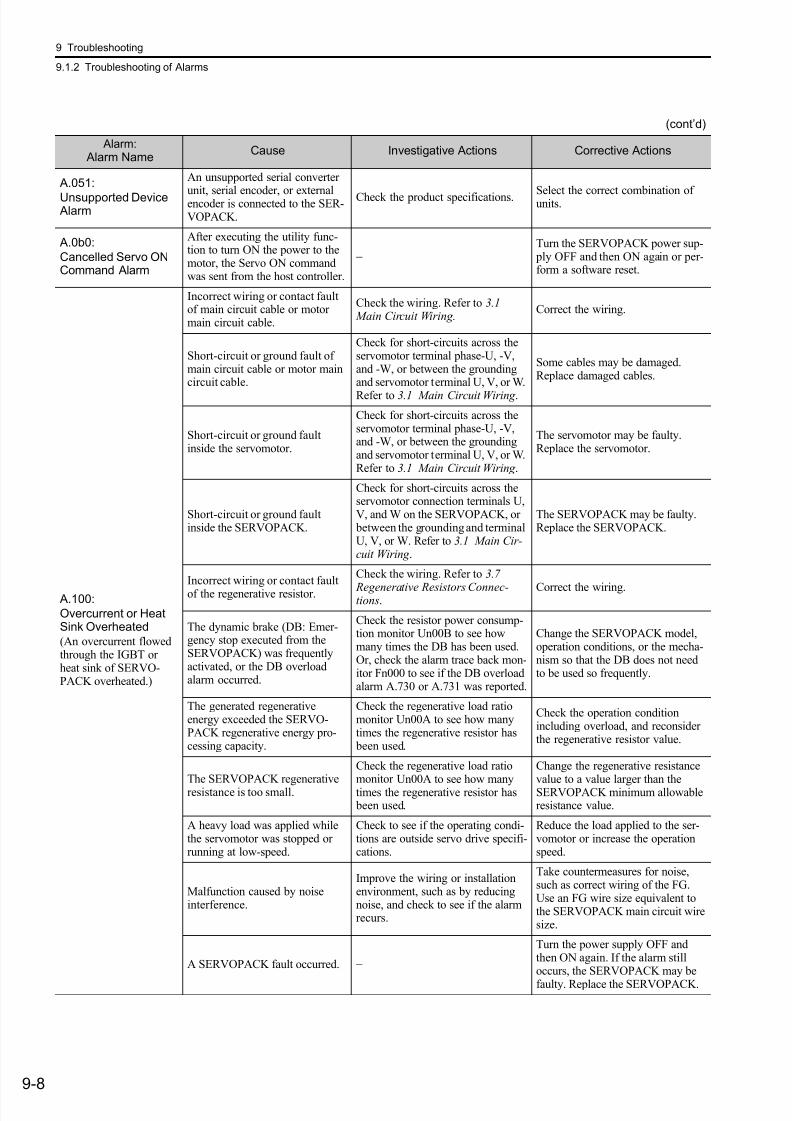
7/17/2019 Manual Yaskawa_servo_drive.pdf
http://slidepdf.com/reader/full/manual-yaskawaservodrivepdf 273/328
9 Troubleshooting
9.1.2 Troubleshooting of Alarms
9-8
A.051:
Unsupported Device Alarm
An unsupported serial converter
unit, serial encoder, or externalencoder is connected to the SER-VOPACK.
Check the product specifications. Select the correct combination ofunits.
A.0b0:
Cancelled Servo ONCommand Alarm
After executing the utility func-tion to turn ON the power to themotor, the Servo ON commandwas sent from the host controller.
−Turn the SERVOPACK power sup- ply OFF and then ON again or per-form a software reset.
A.100:
Overcurrent or HeatSink Overheated
(An overcurrent flowedthrough the IGBT orheat sink of SERVO-PACK overheated.)
Incorrect wiring or contact faultof main circuit cable or motormain circuit cable.
Check the wiring. Refer to 3.1 Main Circuit Wiring.
Correct the wiring.
Short-circuit or ground fault ofmain circuit cable or motor maincircuit cable.
Check for short-circuits across theservomotor terminal phase-U, -V,and -W, or between the groundingand servomotor terminal U, V, or W.
Refer to 3.1 Main Circuit Wiring .
Some cables may be damaged.Replace damaged cables.
Short-circuit or ground faultinside the servomotor.
Check for short-circuits across theservomotor terminal phase-U, -V,and -W, or between the groundingand servomotor terminal U, V, or W.Refer to 3.1 Main Circuit Wiring .
The servomotor may be faulty.Replace the servomotor.
Short-circuit or ground faultinside the SERVOPACK.
Check for short-circuits across theservomotor connection terminals U,V, and W on the SERVOPACK, or between the grounding and terminalU, V, or W. Refer to 3.1 Main Cir-cuit Wiring .
The SERVOPACK may be faulty.Replace the SERVOPACK.
Incorrect wiring or contact faultof the regenerative resistor.
Check the wiring. Refer to 3.7
Regenerative Resistors Connec-tions.
Correct the wiring.
The dynamic brake (DB: Emer-gency stop executed from theSERVOPACK) was frequentlyactivated, or the DB overloadalarm occurred.
Check the resistor power consump-tion monitor Un00B to see howmany times the DB has been used.Or, check the alarm trace back mon-itor Fn000 to see if the DB overloadalarm A.730 or A.731 was reported.
Change the SERVOPACK model,operation conditions, or the mecha-nism so that the DB does not needto be used so frequently.
The generated regenerativeenergy exceeded the SERVO-PACK regenerative energy pro-cessing capacity.
Check the regenerative load ratiomonitor Un00A to see how manytimes the regenerative resistor has been used.
Check the operation conditionincluding overload, and reconsiderthe regenerative resistor value.
The SERVOPACK regenerativeresistance is too small.
Check the regenerative load ratiomonitor Un00A to see how manytimes the regenerative resistor has been used.
Change the regenerative resistancevalue to a value larger than theSERVOPACK minimum allowableresistance value.
A heavy load was applied whilethe servomotor was stopped orrunning at low-speed.
Check to see if the operating condi-tions are outside servo drive specifi-cations.
Reduce the load applied to the ser-vomotor or increase the operationspeed.
Malfunction caused by noiseinterference.
Improve the wiring or installationenvironment, such as by reducingnoise, and check to see if the alarmrecurs.
Take countermeasures for noise,such as correct wiring of the FG.Use an FG wire size equivalent tothe SERVOPACK main circuit wiresize.
A SERVOPACK fault occurred. −
Turn the power supply OFF andthen ON again. If the alarm stilloccurs, the SERVOPACK may be
faulty. Replace the SERVOPACK.
(cont’d)
Alarm: Alarm Name
Cause Investigative Actions Corrective Actions
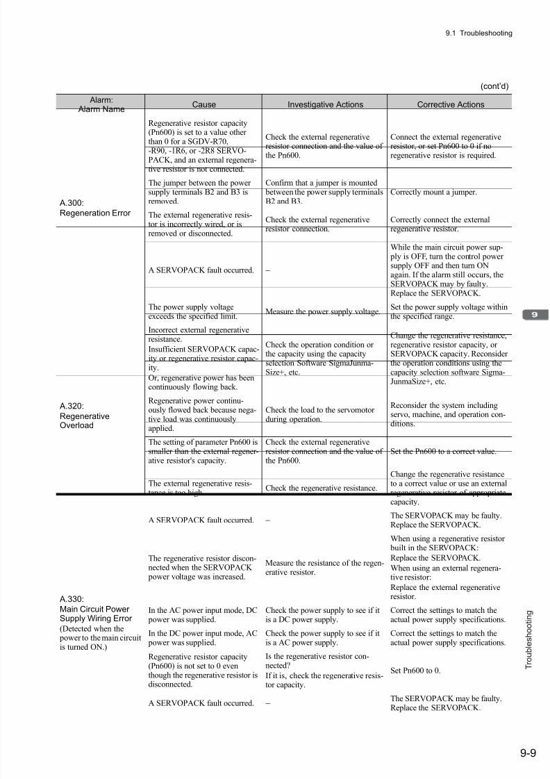
7/17/2019 Manual Yaskawa_servo_drive.pdf
http://slidepdf.com/reader/full/manual-yaskawaservodrivepdf 274/328
9.1 Troubleshooting
9-9
T r o u b l e s h o o t i n g
A.300:
Regeneration Error
Regenerative resistor capacity
(Pn600) is set to a value otherthan 0 for a SGDV-R70,-R90, -1R6, or -2R8 SERVO-PACK, and an external regenera-tive resistor is not connected.
Check the external regenerativeresistor connection and the value ofthe Pn600.
Connect the external regenerativeresistor, or set Pn600 to 0 if noregenerative resistor is required.
The jumper between the powersupply terminals B2 and B3 isremoved.
Confirm that a jumper is mounted between the power supply terminalsB2 and B3.
Correctly mount a jumper.
The external regenerative resis-tor is incorrectly wired, or isremoved or disconnected.
Check the external regenerativeresistor connection.
Correctly connect the externalregenerative resistor.
A SERVOPACK fault occurred. −
While the main circuit power sup- ply is OFF, turn the control powersupply OFF and then turn ON
again. If the alarm still occurs, theSERVOPACK may by faulty.Replace the SERVOPACK.
A.320:RegenerativeOverload
The power supply voltageexceeds the specified limit.
Measure the power supply voltage.Set the power supply voltage withinthe specified range.
Incorrect external regenerativeresistance.
Insufficient SERVOPACK capac-ity or regenerative resistor capac-ity.
Or, regenerative power has beencontinuously flowing back.
Check the operation condition orthe capacity using the capacityselection Software SigmaJunma-Size+, etc.
Change the regenerative resistance,regenerative resistor capacity, orSERVOPACK capacity. Reconsiderthe operation conditions using thecapacity selection software Sigma-JunmaSize+, etc.
Regenerative power continu-
ously flowed back because nega-tive load was continuouslyapplied.
Check the load to the servomotorduring operation.
Reconsider the system includingservo, machine, and operation con-ditions.
The setting of parameter Pn600 issmaller than the external regener-ative resistor's capacity.
Check the external regenerativeresistor connection and the value ofthe Pn600.
Set the Pn600 to a correct value.
The external regenerative resis-tance is too high.
Check the regenerative resistance.
Change the regenerative resistanceto a correct value or use an externalregenerative resistor of appropriatecapacity.
A SERVOPACK fault occurred. − The SERVOPACK may be faulty.Replace the SERVOPACK.
A.330:
Main Circuit PowerSupply Wiring Error
(Detected when the power to the main circuitis turned ON.)
The regenerative resistor discon-nected when the SERVOPACK power voltage was increased.
Measure the resistance of the regen-erative resistor.
When using a regenerative resistor
built in the SERVOPACK:Replace the SERVOPACK.
When using an external regenera-tive resistor:
Replace the external regenerativeresistor.
In the AC power input mode, DC power was supplied.
Check the power supply to see if itis a DC power supply.
Correct the settings to match theactual power supply specifications.
In the DC power input mode, AC power was supplied.
Check the power supply to see if itis a AC power supply.
Correct the settings to match theactual power supply specifications.
Regenerative resistor capacity(Pn600) is not set to 0 eventhough the regenerative resistor is
disconnected.
Is the regenerative resistor con-nected?
If it is, check the regenerative resis-
tor capacity.
Set Pn600 to 0.
A SERVOPACK fault occurred. − The SERVOPACK may be faulty.Replace the SERVOPACK.
(cont’d)
Alarm: Alarm Name
Cause Investigative Actions Corrective Actions
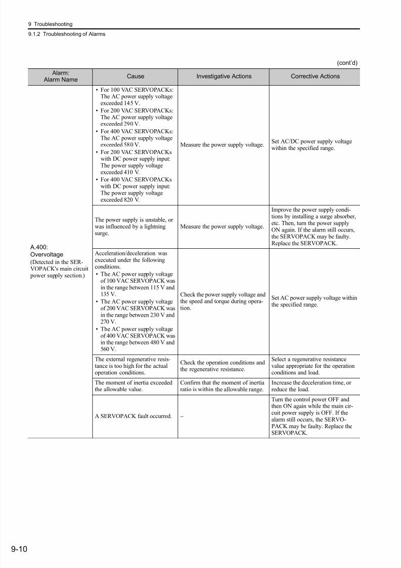
7/17/2019 Manual Yaskawa_servo_drive.pdf
http://slidepdf.com/reader/full/manual-yaskawaservodrivepdf 275/328
9 Troubleshooting
9.1.2 Troubleshooting of Alarms
9-10
A.400:
Overvoltage
(Detected in the SER-VOPACK's main circuit power supply section.)
• For 100 VAC SERVOPACKs:
The AC power supply voltageexceeded 145 V.
• For 200 VAC SERVOPACKs:The AC power supply voltageexceeded 290 V.
• For 400 VAC SERVOPACKs:The AC power supply voltageexceeded 580 V.
• For 200 VAC SERVOPACKswith DC power supply input:The power supply voltageexceeded 410 V.
• For 400 VAC SERVOPACKswith DC power supply input:The power supply voltage
exceeded 820 V.
Measure the power supply voltage.Set AC/DC power supply voltagewithin the specified range.
The power supply is unstable, orwas influenced by a lightningsurge.
Measure the power supply voltage.
Improve the power supply condi-tions by installing a surge absorber,etc. Then, turn the power supplyON again. If the alarm still occurs,the SERVOPACK may be faulty.Replace the SERVOPACK.
Acceleration/deceleration wasexecuted under the followingconditions.
• The AC power supply voltageof 100 VAC SERVOPACK wasin the range between 115 V and135 V.
• The AC power supply voltageof 200 VAC SERVOPACK wasin the range between 230 V and270 V.
• The AC power supply voltageof 400 VAC SERVOPACK wasin the range between 480 V and560 V.
Check the power supply voltage andthe speed and torque during opera-tion.
Set AC power supply voltage withinthe specified range.
The external regenerative resis-tance is too high for the actualoperation conditions.
Check the operation conditions andthe regenerative resistance.
Select a regenerative resistancevalue appropriate for the operationconditions and load.
The moment of inertia exceededthe allowable value.
Confirm that the moment of inertiaratio is within the allowable range.
Increase the deceleration time, orreduce the load.
A SERVOPACK fault occurred. −
Turn the control power OFF andthen ON again while the main cir-cuit power supply is OFF. If thealarm still occurs, the SERVO-PACK may be faulty. Replace theSERVOPACK.
(cont’d)
Alarm: Alarm Name
Cause Investigative Actions Corrective Actions
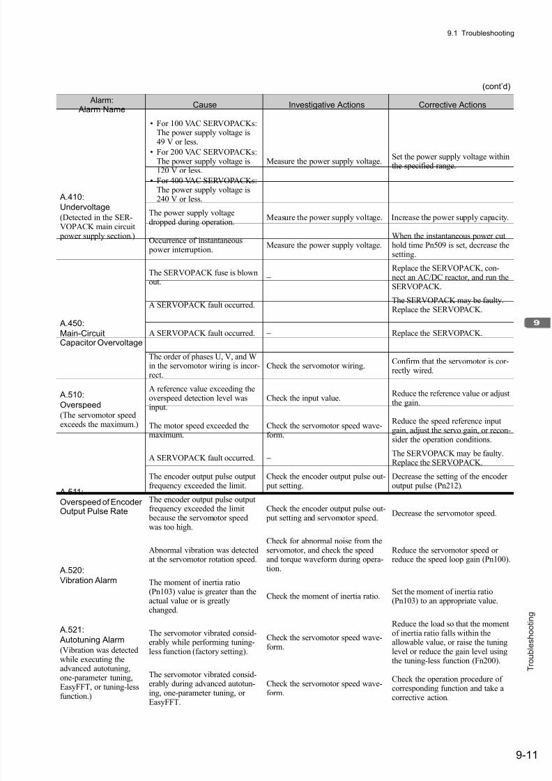
7/17/2019 Manual Yaskawa_servo_drive.pdf
http://slidepdf.com/reader/full/manual-yaskawaservodrivepdf 276/328
9.1 Troubleshooting
9-11
T r o u b l e s h o o t i n g
A.410:
Undervoltage
(Detected in the SER-VOPACK main circuit power supply section.)
• For 100 VAC SERVOPACKs:
The power supply voltage is49 V or less.
• For 200 VAC SERVOPACKs:The power supply voltage is120 V or less.
• For 400 VAC SERVOPACKs:The power supply voltage is240 V or less.
Measure the power supply voltage.Set the power supply voltage withinthe specified range.
The power supply voltagedropped during operation.
Measure the power supply voltage. Increase the power supply capacity.
Occurrence of instantaneous power interruption.
Measure the power supply voltage.When the instantaneous power cuthold time Pn509 is set, decrease thesetting.
The SERVOPACK fuse is blownout. −
Replace the SERVOPACK, con-nect an AC/DC reactor, and run theSERVOPACK.
A SERVOPACK fault occurred. − The SERVOPACK may be faulty.Replace the SERVOPACK.
A.450:
Main-CircuitCapacitor Overvoltage
A SERVOPACK fault occurred. − Replace the SERVOPACK.
A.510:
Overspeed
(The servomotor speedexceeds the maximum.)
The order of phases U, V, and Win the servomotor wiring is incor-rect.
Check the servomotor wiring.Confirm that the servomotor is cor-rectly wired.
A reference value exceeding theoverspeed detection level was
input.
Check the input value.Reduce the reference value or adjustthe gain.
The motor speed exceeded themaximum.
Check the servomotor speed wave-form.
Reduce the speed reference inputgain, adjust the servo gain, or recon-sider the operation conditions.
A SERVOPACK fault occurred. − The SERVOPACK may be faulty.Replace the SERVOPACK.
A.511:
Overspeed of EncoderOutput Pulse Rate
The encoder output pulse outputfrequency exceeded the limit.
Check the encoder output pulse out- put setting.
Decrease the setting of the encoderoutput pulse (Pn212).
The encoder output pulse outputfrequency exceeded the limit because the servomotor speedwas too high.
Check the encoder output pulse out- put setting and servomotor speed.
Decrease the servomotor speed.
A.520:
Vibration Alarm
Abnormal vibration was detectedat the servomotor rotation speed.
Check for abnormal noise from the
servomotor, and check the speedand torque waveform during opera-tion.
Reduce the servomotor speed orreduce the speed loop gain (Pn100).
The moment of inertia ratio(Pn103) value is greater than theactual value or is greatlychanged.
Check the moment of inertia ratio.Set the moment of inertia ratio(Pn103) to an appropriate value.
A.521:
Autotuning Alarm
(Vibration was detectedwhile executing theadvanced autotuning,one-parameter tuning,
EasyFFT, or tuning-lessfunction.)
The servomotor vibrated consid-erably while performing tuning-less function (factory setting).
Check the servomotor speed wave-form.
Reduce the load so that the momentof inertia ratio falls within theallowable value, or raise the tuninglevel or reduce the gain level usingthe tuning-less function (Fn200).
The servomotor vibrated consid-
erably during advanced autotun-ing, one-parameter tuning, orEasyFFT.
Check the servomotor speed wave-form.
Check the operation procedure ofcorresponding function and take acorrective action.
(cont’d)
Alarm: Alarm Name
Cause Investigative Actions Corrective Actions

7/17/2019 Manual Yaskawa_servo_drive.pdf
http://slidepdf.com/reader/full/manual-yaskawaservodrivepdf 277/328
9 Troubleshooting
9.1.2 Troubleshooting of Alarms
9-12
A.710: A.720:
Overload
A.710: High Load
A.720: Low Load
Incorrect wiring or contact fault
of servomotor and encoder.
Check the wiring.Confirm that the servomotor and
encoder are correctly wired.
Operation beyond the overload protection characteristics.
Check the servomotor overloadcharacteristics and executed runcommand.
Reconsider the load conditions andoperation conditions. Or, increasethe servomotor capacity.
Excessive load was applied dur-ing operation because the servo-motor was not driven due tomechanical problems.
Check the executed run commandand servomotor speed.
Remove the mechanical problems.
A SERVOPACK fault occurred. − The SERVOPACK may be faulty.Replace the SERVOPACK.
A.730:
A.731:Dynamic BrakeOverload
(An excessive powerconsumption of dynamic brake was detected.)
The servomotor rotates becauseof external force.
Check the operation status.Take measures to ensure the servo-motor will not rotate because ofexternal force.
The rotating energy at a DB stopexceeds the DB resistance capac-ity.
Check the DB resistor power con-sumption monitor (Un00B) to seehow many times the DB has beenused.
• Reduce the servomotor referencespeed.
• Reduce the moment of inertiaratio.
• Reduce the number of times ofthe DB stop operation.
A SERVOPACK fault occurred. − The SERVOPACK may be faulty.Replace the SERVOPACK.
A.740:
Overload of SurgeCurrent Limit Resistor
(The main circuit poweris turned ON/OFF toofrequently.)
The inrush current limit resistoroperation frequency at the maincircuit power supply ON/OFFoperation exceeds the allowablerange.
−Reduce the frequency of turning themain circuit power supply ON/OFF.
A SERVOPACK fault occurred. − The SERVOPACK may be faulty.Replace the SERVOPACK.
A.7A0:
Heat Sink Overheated
(Detected when the heatsink temperatureexceeds 100°C.)
The surrounding air temperatureis too high.
Check the surrounding air tempera-ture using a thermostat.
Decrease the surrounding air tem- perature by improving the SERVO-PACK installation conditions.
The overload alarm has beenreset by turning OFF the powertoo many times.
Check the alarm trace back monitor(Fn000) to see if the overload alarmwas reported.
Change the method for resetting thealarm.
Excessive load or operation beyond the regenerative energy processing capacity.
Check the accumulated load ratiomonitor Un009 to see the load dur-ing operation, and the regenerativeload ratio monitor Un00A to see theregenerative energy processing
capacity.
Reconsider the load and operationconditions.
Incorrect SERVOPACK installa-tion orientation or/and insuffi-cient space around theSERVOPACK.
Check the SERVOPACK installa-tion conditions.
Install the SERVOPACK correctlyas specified.
A SERVOPACK fault occurred. − The SERVOPACK may be faulty.Replace the SERVOPACK.
A.7AB:
Built-in Fan inSERVOPACKStopped
The fan inside the SERVOPACKstopped.
Check for foreign matter or debrisinside the SERVOPACK.
Remove foreign matter or debrisfrom the SERVOPACK. If thealarm still occurs, the SERVO-PACK may be faulty. Replace theSERVOPACK.
(cont’d)
Alarm: Alarm Name
Cause Investigative Actions Corrective Actions

7/17/2019 Manual Yaskawa_servo_drive.pdf
http://slidepdf.com/reader/full/manual-yaskawaservodrivepdf 278/328
9.1 Troubleshooting
9-13
T r o u b l e s h o o t i n g
A.810:
Encoder Backup Error
(Detected on the encoderside)
(Only when an absoluteencoder is connected.)
Alarm occurred when the power
to the absolute encoder was ini-tially turned ON.
Check to see if the power was
turned ON initially. Set up the encoder (Fn008).
The encoder cable was discon-nected, and was connected again.
Check to see if the power wasturned ON initially.
Confirm the connection and set upthe encoder (Fn008).
The power from both the control power supply (+5 V) and the bat-tery power supply from the SER-VOPACK is not being supplied.
Check the encoder connector bat-tery or the connector contact status.
Replace the battery or take similarmeasures to supply power to theencoder, and set up the encoder(Fn008).
An absolute encoder faultoccurred.
−If the alarm cannot be reset by set-ting up the encoder again, replacethe servomotor.
A SERVOPACK fault occurred. − The SERVOPACK may be faulty.Replace the SERVOPACK.
A.820:
Encoder ChecksumError (Detected on the encoderside.)
An encoder fault occurred. −
Set up the encoder again usingFn008. If the alarm still occurs, theservomotor may be faulty. Replacethe servomotor.
A SERVOPACK fault occurred. − The SERVOPACK may be faulty.Replace the SERVOPACK.
A.830:
Absolute EncoderBattery Error
(The absolute encoder battery voltage is lowerthan the specified value.)
The battery connection is incor-rect.
Check the battery connection. Reconnect the battery.
The battery voltage is lower thanthe specified value 2.7 V.
Measure the battery voltage. Replace the battery.
A SERVOPACK fault occurred. − The SERVOPACK may be faulty.Replace the SERVOPACK.
A.840:
Encoder Data Error
(Detected on the encoderside.)
An encoder fault occurred. −Turn the power supply OFF andthen ON again. If the alarm stilloccurs, the servomotor may befaulty. Replace the servomotor.
Malfunction of encoder becauseof noise interference, etc.
−
Correct the wiring around theencoder by separating the encodercable from the servomotor main cir-cuit cable or by checking thegrounding and other wiring.
A.850:
Encoder Overspeed
(Detected when the con-trol power supply wasturned ON.)
(Detected on the encoderside.)
The servomotor was running at
200 min-1 or higher when thecontrol power supply was turnedON.
Check the speed monitor (Un000)to confirm the servomotor speedwhen the power is turned ON.
Reduce the servomotor speed to a
value less than 200 min-1, and turnON the control power supply.
An encoder fault occurred. −Turn the power supply OFF andthen ON again. If the alarm stilloccurs, the servomotor may befaulty. Replace the servomotor.
A SERVOPACK fault occurred. −
Turn the power supply OFF andthen ON again. If the alarm stilloccurs, the SERVOPACK may befaulty. Replace the SERVOPACK.
(cont’d)
Alarm: Alarm Name
Cause Investigative Actions Corrective Actions
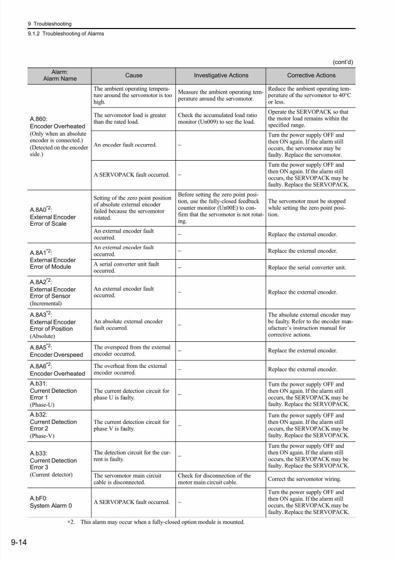
7/17/2019 Manual Yaskawa_servo_drive.pdf
http://slidepdf.com/reader/full/manual-yaskawaservodrivepdf 279/328
9 Troubleshooting
9.1.2 Troubleshooting of Alarms
9-14
A.860:
Encoder Overheated
(Only when an absoluteencoder is connected.)
(Detected on the encoderside.)
The ambient operating tempera-
ture around the servomotor is toohigh.
Measure the ambient operating tem-
perature around the servomotor.
Reduce the ambient operating tem-
perature of the servomotor to 40°
Cor less.
The servomotor load is greaterthan the rated load.
Check the accumulated load ratiomonitor (Un009) to see the load.
Operate the SERVOPACK so thatthe motor load remains within thespecified range.
An encoder fault occurred. −
Turn the power supply OFF andthen ON again. If the alarm stilloccurs, the servomotor may befaulty. Replace the servomotor.
A SERVOPACK fault occurred. −
Turn the power supply OFF andthen ON again. If the alarm stilloccurs, the SERVOPACK may befaulty. Replace the SERVOPACK.
A.8A0*2:
External EncoderError of Scale
Setting of the zero point positionof absolute external encoderfailed because the servomotorrotated.
Before setting the zero point posi-tion, use the fully-closed feedbackcounter monitor (Un00E) to con-firm that the servomotor is not rotat-ing.
The servomotor must be stoppedwhile setting the zero point posi-tion.
An external encoder faultoccurred.
− Replace the external encoder.
A.8A1*2:
External EncoderError of Module
An external encoder faultoccurred.
− Replace the external encoder.
A serial converter unit faultoccurred.
− Replace the serial converter unit.
A.8A2*2:
External Encoder
Error of Sensor (Incremental)
An external encoder fault
occurred. −
Replace the external encoder.
A.8A3*2:
External EncoderError of Position
(Absolute)
An absolute external encoderfault occurred.
−
The absolute external encoder may be faulty. Refer to the encoder man-ufacture’s instruction manual forcorrective actions.
A.8A5*2:
Encoder Overspeed
The overspeed from the externalencoder occurred.
− Replace the external encoder.
A.8A6*2:
Encoder Overheated
The overheat from the externalencoder occurred.
− Replace the external encoder.
A.b31:
Current DetectionError 1
(Phase-U)
The current detection circuit for phase U is faulty. −
Turn the power supply OFF and
then ON again. If the alarm stilloccurs, the SERVOPACK may befaulty. Replace the SERVOPACK.
A.b32:
Current DetectionError 2
(Phase-V)
The current detection circuit for phase V is faulty.
−
Turn the power supply OFF andthen ON again. If the alarm stilloccurs, the SERVOPACK may befaulty. Replace the SERVOPACK.
A.b33:
Current DetectionError 3
(Current detector)
The detection circuit for the cur-rent is faulty.
−
Turn the power supply OFF andthen ON again. If the alarm stilloccurs, the SERVOPACK may befaulty. Replace the SERVOPACK.
The servomotor main circuitcable is disconnected.
Check for disconnection of themotor main circuit cable.
Correct the servomotor wiring.
A.bF0:
System Alarm 0A SERVOPACK fault occurred. −
Turn the power supply OFF andthen ON again. If the alarm stilloccurs, the SERVOPACK may befaulty. Replace the SERVOPACK.
∗2. This alarm may occur when a fully-closed option module is mounted.
(cont’d)
Alarm:
Alarm NameCause Investigative Actions Corrective Actions
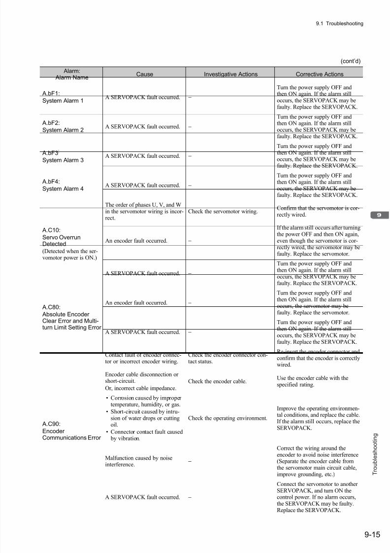
7/17/2019 Manual Yaskawa_servo_drive.pdf
http://slidepdf.com/reader/full/manual-yaskawaservodrivepdf 280/328
9.1 Troubleshooting
9-15
T r o u b l e s h o o t i n g
A.bF1:
System Alarm 1 A SERVOPACK fault occurred. −
Turn the power supply OFF and
then ON again. If the alarm stilloccurs, the SERVOPACK may befaulty. Replace the SERVOPACK.
A.bF2:
System Alarm 2A SERVOPACK fault occurred. −
Turn the power supply OFF andthen ON again. If the alarm stilloccurs, the SERVOPACK may befaulty. Replace the SERVOPACK.
A.bF3:
System Alarm 3A SERVOPACK fault occurred. −
Turn the power supply OFF andthen ON again. If the alarm stilloccurs, the SERVOPACK may befaulty. Replace the SERVOPACK.
A.bF4:
System Alarm 4A SERVOPACK fault occurred. −
Turn the power supply OFF andthen ON again. If the alarm stilloccurs, the SERVOPACK may be
faulty. Replace the SERVOPACK.
A.C10:
Servo OverrunDetected
(Detected when the ser-vomotor power is ON.)
The order of phases U, V, and Win the servomotor wiring is incor-rect.
Check the servomotor wiring.Confirm that the servomotor is cor-rectly wired.
An encoder fault occurred. −
If the alarm still occurs after turningthe power OFF and then ON again,even though the servomotor is cor-rectly wired, the servomotor may befaulty. Replace the servomotor.
A SERVOPACK fault occurred. −
Turn the power supply OFF andthen ON again. If the alarm stilloccurs, the SERVOPACK may befaulty. Replace the SERVOPACK.
A.C80:
Absolute EncoderClear Error and Multi-turn Limit Setting Error
An encoder fault occurred. −
Turn the power supply OFF andthen ON again. If the alarm stilloccurs, the servomotor may befaulty. Replace the servomotor.
A SERVOPACK fault occurred. −
Turn the power supply OFF andthen ON again. If the alarm stilloccurs, the SERVOPACK may befaulty. Replace the SERVOPACK.
A.C90:
EncoderCommunications Error
Contact fault of encoder connec-tor or incorrect encoder wiring.
Check the encoder connector con-tact status.
Re-insert the encoder connector andconfirm that the encoder is correctlywired.
Encoder cable disconnection orshort-circuit.
Or, incorrect cable impedance.
Check the encoder cable.Use the encoder cable with the
specified rating.
• Corrosion caused by impropertemperature, humidity, or gas.
• Short-circuit caused by intru-sion of water drops or cuttingoil.
• Connector contact fault caused by vibration.
Check the operating environment.
Improve the operating environmen-tal conditions, and replace the cable.If the alarm still occurs, replace theSERVOPACK.
Malfunction caused by noiseinterference.
−
Correct the wiring around theencoder to avoid noise interference(Separate the encoder cable fromthe servomotor main circuit cable,improve grounding, etc.)
A SERVOPACK fault occurred. −
Connect the servomotor to anotherSERVOPACK, and turn ON thecontrol power. If no alarm occurs,the SERVOPACK may be faulty.Replace the SERVOPACK.
(cont’d)
Alarm: Alarm Name
Cause Investigative Actions Corrective Actions
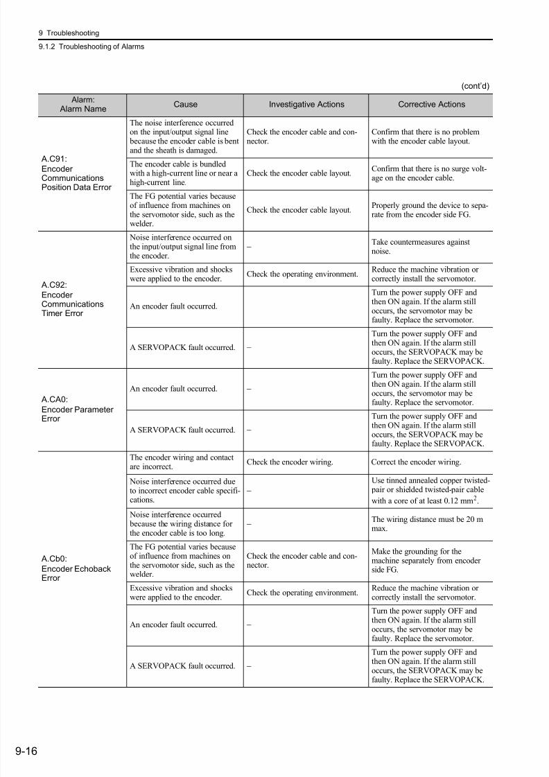
7/17/2019 Manual Yaskawa_servo_drive.pdf
http://slidepdf.com/reader/full/manual-yaskawaservodrivepdf 281/328
9 Troubleshooting
9.1.2 Troubleshooting of Alarms
9-16
A.C91:
EncoderCommunicationsPosition Data Error
The noise interference occurred
on the input/output signal line because the encoder cable is bentand the sheath is damaged.
Check the encoder cable and con-nector. Confirm that there is no problemwith the encoder cable layout.
The encoder cable is bundledwith a high-current line or near ahigh-current line.
Check the encoder cable layout.Confirm that there is no surge volt-age on the encoder cable.
The FG potential varies becauseof influence from machines onthe servomotor side, such as thewelder.
Check the encoder cable layout.Properly ground the device to sepa-rate from the encoder side FG.
A.C92:
EncoderCommunicationsTimer Error
Noise interference occurred onthe input/output signal line fromthe encoder.
− Take countermeasures againstnoise.
Excessive vibration and shockswere applied to the encoder. Check the operating environment. Reduce the machine vibration orcorrectly install the servomotor.
An encoder fault occurred. −
Turn the power supply OFF andthen ON again. If the alarm stilloccurs, the servomotor may befaulty. Replace the servomotor.
A SERVOPACK fault occurred. −
Turn the power supply OFF andthen ON again. If the alarm stilloccurs, the SERVOPACK may befaulty. Replace the SERVOPACK.
A.CA0:
Encoder ParameterError
An encoder fault occurred. −
Turn the power supply OFF andthen ON again. If the alarm stilloccurs, the servomotor may befaulty. Replace the servomotor.
A SERVOPACK fault occurred. −
Turn the power supply OFF andthen ON again. If the alarm stilloccurs, the SERVOPACK may befaulty. Replace the SERVOPACK.
A.Cb0:
Encoder EchobackError
The encoder wiring and contactare incorrect.
Check the encoder wiring. Correct the encoder wiring.
Noise interference occurred dueto incorrect encoder cable specifi-cations.
−Use tinned annealed copper twisted- pair or shielded twisted-pair cable
with a core of at least 0.12 mm2.
Noise interference occurred because the wiring distance forthe encoder cable is too long.
− The wiring distance must be 20 mmax.
The FG potential varies becauseof influence from machines onthe servomotor side, such as thewelder.
Check the encoder cable and con-nector.
Make the grounding for themachine separately from encoderside FG.
Excessive vibration and shockswere applied to the encoder.
Check the operating environment.Reduce the machine vibration orcorrectly install the servomotor.
An encoder fault occurred. −
Turn the power supply OFF andthen ON again. If the alarm stilloccurs, the servomotor may befaulty. Replace the servomotor.
A SERVOPACK fault occurred. −
Turn the power supply OFF andthen ON again. If the alarm stilloccurs, the SERVOPACK may be
faulty. Replace the SERVOPACK.
(cont’d)
Alarm: Alarm Name
Cause Investigative Actions Corrective Actions

7/17/2019 Manual Yaskawa_servo_drive.pdf
http://slidepdf.com/reader/full/manual-yaskawaservodrivepdf 282/328
9.1 Troubleshooting
9-17
T r o u b l e s h o o t i n g
A.CC0:
Multi-turn LimitDisagreement
When using a direct-drive (DD)
servomotor, the multi-turn limitvalue (Pn205) is different fromthat of the encoder.
Check the value of the Pn205. Correct the setting of Pn205 (0 to65535).
The multi-turn limit value of theencoder is different from that ofthe SERVOPACK. Or, the multi-turn limit value of the SERVO-PACK has been changed.
Check the value of the Pn205 of theSERVOPACK.
Execute Fn013 at the occurrence ofalarm.
A SERVOPACK fault occurred. −
Turn the power supply OFF andthen ON again. If the alarm stilloccurs, the SERVOPACK may befaulty. Replace the SERVOPACK.
A.CF1*2:
Feedback OptionModuleCommunications Error
(Reception error)
Wiring of cable between serialconverter unit and SERVOPACK
is incorrect or contact is faulty.
Check the external encoder wiring. Correct the cable wiring.
The specified cable is not used between serial converter unit andSERVOPACK.
Confirm the external encoder wir-ing specifications.
Use the specified cable.
Cable between serial converterunit and SERVOPACK is toolong.
Measure the external encoder cablelength.
Use 20 m cable max.
Sheath of cable between serialconverter unit and SERVOPACKis broken.
Check the external encoder cable. Replace the cable.
A.CF2*2:
Feedback OptionModuleCommunications Error
(Timer stop)
Noise interferes with the cable between serial converter unit and
SERVOPACK.
−
Correct the wiring around serialconverter unit, e.g., separatinginput/output signal line from maincircuit cable or grounding.
A serial converter unit faultoccurred.
− Replace the serial converter unit.
A SERVOPACK fault occurred. − Replace the SERVOPACK.
A.d00:
Position Error Pulse
Overflow(Position error exceededthe value set in theexcessive position erroralarm level (Pn520))
The contact in the servomotor U,V, and W wirings is faulty.
Check the motor main circuit cableconnection.
Confirm that there is no contactfault in the motor wiring of encoderwiring.
The frequency of the position ref-erence is too high.
Reduce the reference frequency, andoperate the SERVOPACK.
Reduce the position reference fre-quency or reference acceleration.Or, reconsider the electronic gearratio.
The position reference accelera-tion is too fast.
Reduce the reference acceleration,and operate the SERVOPACK.
Apply the smoothing function, such
as using position reference accelera-tion/deceleration time constant(Pn216).
Setting of the Pn520 (ExcessivePosition Error Alarm Level) islow against the operating condi-tion.
Check the alarm level (Pn520) tosee if it is set to an appropriatevalue.
Set the Pn520 to proper value.
A SERVOPACK fault occurred. −
Turn the power supply OFF andthen ON again. If the alarm stilloccurs, the SERVOPACK may befaulty. Replace the SERVOPACK.
A.d01:
Position Error PulseOverflow Alarm atServo ON
The servo ON command is
received when the number of position error pulses is greaterthan the set value of Pn526.
Check the error counter monitor
(Un008) while the servomotor power is OFF.
Make the setting so that the positionerror pulse is cleared when the
servo is OFF.Or, correct the excessive positionerror alarm level at servo ON(Pn526).
∗2. This alarm may occur when a fully-closed option module is mounted.
(cont’d)
Alarm: Alarm Name
Cause Investigative Actions Corrective Actions
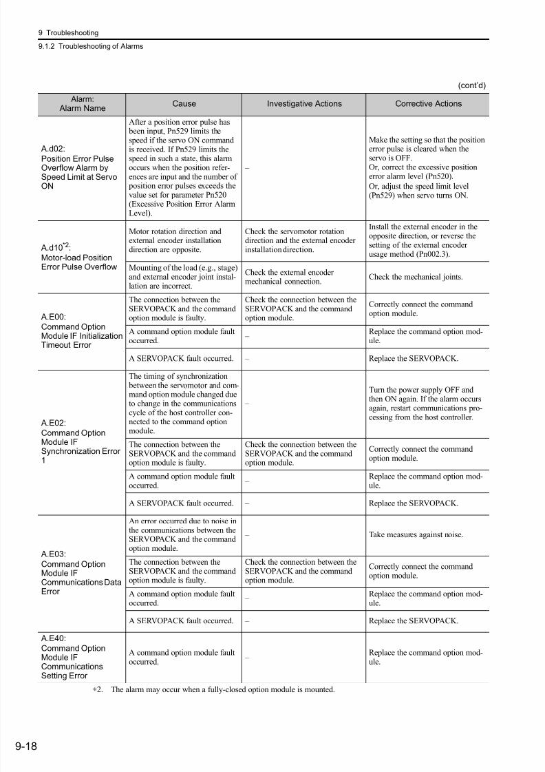
7/17/2019 Manual Yaskawa_servo_drive.pdf
http://slidepdf.com/reader/full/manual-yaskawaservodrivepdf 283/328
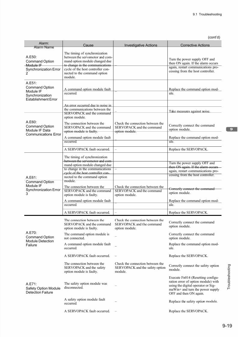
7/17/2019 Manual Yaskawa_servo_drive.pdf
http://slidepdf.com/reader/full/manual-yaskawaservodrivepdf 284/328
9.1 Troubleshooting
9-19
T r o u b l e s h o o t i n g
A.E50:
Command OptionModule IFSynchronization Error2
The timing of synchronization
between the servomotor and com-mand option module changed dueto change in the communicationscycle of the host controller con-nected to the command optionmodule.
–
Turn the power supply OFF andthen ON again. If the alarm occursagain, restart communications pro-cessing from the host controller.
A.E51:
Command OptionModule IFSynchronizationEstablishment Error
A command option module faultoccurred.
– Replace the command option mod-ule.
A.E60:
Command OptionModule IF DataCommunications Error
An error occurred due to noise inthe communications between theSERVOPACK and the command
option module.
– Take measures against noise.
The connection between theSERVOPACK and the commandoption module is faulty.
Check the connection between theSERVOPACK and the commandoption module.
Correctly connect the commandoption module.
A command option module faultoccurred.
– Replace the command option mod-ule.
A SERVOPACK fault occurred. – Replace the SERVOPACK.
A.E61:Command OptionModule IFSynchronization Error3
The timing of synchronization between the servomotor and com-mand option module changed dueto change in the communicationscycle of the host controller con-
nected to the command optionmodule.
–
Turn the power supply OFF andthen ON again. If the alarm occursagain, restart communications pro-cessing from the host controller.
The connection between theSERVOPACK and the commandoption module is faulty.
Check the connection between theSERVOPACK and the commandoption module.
Correctly connect the commandoption module.
A command option module faultoccurred.
– Replace the command option mod-ule.
A SERVOPACK fault occurred. – Replace the SERVOPACK.
A.E70:
Command OptionModule DetectionFailure
The connection between theSERVOPACK and the commandoption module is faulty.
Check the connection between theSERVOPACK and the commandoption module.
Correctly connect the commandoption module.
The command option module isnot connected. –
Correctly connect the commandoption module.
A command option module faultoccurred.
– Replace the command option mod-ule.
A SERVOPACK fault occurred. – Replace the SERVOPACK.
A.E71:
Safety Option ModuleDetection Failure
The connection between theSERVOPACK and the safetyoption module is faulty.
Check the connection between theSERVOPACK and the safety optionmodule.
Correctly connect the safety optionmodule.
The safety option module wasdisconnected.
–
Execute Fn014 (Resetting configu-ration error of option module) withusing the digital operator or Sig-maWin+ and turn the power supply
OFF and then ON again.A safety option module faultoccurred.
– Replace the safety option module.
A SERVOPACK fault occurred. – Replace the SERVOPACK.
(cont’d)
Alarm: Alarm Name
Cause Investigative Actions Corrective Actions

7/17/2019 Manual Yaskawa_servo_drive.pdf
http://slidepdf.com/reader/full/manual-yaskawaservodrivepdf 285/328
9 Troubleshooting
9.1.2 Troubleshooting of Alarms
9-20
A.E72*2:
Feedback OptionModule DetectionFailure
The connection between the
SERVOPACK and the feedbackoption module is faulty.
Check the connection between the
SERVOPACK and the feedbackoption module.
Correctly connect the feedback
option module.
The feedback option module wasdisconnected.
–
Execute Fn014 (Resetting configu-ration error of option module) withthe digital operator or SigmaWin+and turn the power supply OFF andthen ON again.
A feedback option module faultoccurred.
– Replace the feedback option mod-ule.
A SERVOPACK fault occurred. – Replace the SERVOPACK.
A.E73:
Unsupported Option
Module
A command option module faultoccurred.
– Replace the command option mod-ule.
A unsupported command optionmodule was connected.
Refer to the catalog of the con-nected command option module.
Connect a compatible commandoption module.
A.E74:
Unsupported SafetyOption Module
A safety option module faultoccurred.
– Replace the safety option module.
A unsupported safety optionmodule was connected.
Refer to the catalog of the con-nected safety option module.
Connect a compatible safety optionmodule.
A.E75*2:
UnsupportedFeedback OptionModule
A feedback option module faultoccurred.
– Replace the feedback option mod-ule.
A unsupported feedback optionmodule was connected.
Refer to the catalog of the con-nected feedback option module orthe manual of the SERVOPACK.
Connect a compatible feedbackoption module.
A.E80:
Command OptionModule UnmatchedError
The command option module wasreplaced with a different model.
–
Execute Fn014 (Resetting configu-
ration error of option module) withthe digital operator or SigmaWin+and turn the power supply OFF andthen ON again.
A.EA2:
DRV Alarm 2
(SERVOPACK WDCerror)
The timing of synchronization between the servomotor andcommand option module changeddue to change in the communica-tions cycle of the host controllerconnected to the command optionmodule.
–
Turn the power supply OFF andthen ON again. If the alarm occursagain, restart communications processing from the host controller.
The connection between theSERVOPACK and the commandoption module is faulty.
Check the connection between theSERVOPACK and the commandoption module.
Correctly connect the commandoption module.
A command option module faultoccurred.
− Replace the command option mod-ule.
A SERVOPACK fault occurred. − Replace the SERVOPACK.
A.Eb1:
Safety Function SignalInput Timing Error
The lag between activations ofthe input signals /HWBB1 and/HWBB2 for the HWBB functionis 10 seconds or more.
Measure the time lag between the/HWBB1 and /HWBB2 signals.
The host controller output signalcircuits or devices for /HWBB1 and/HWBB2 or the SERVOPACKinput signal circuits may be faulty.Alternatively, the input signalcables may be disconnected. Repairor replace them.
A.ED1:
Command OptionModule IF CommandTimeout Error
Processing of the sensor ONcommand from the commandoption module is not completed.
− Input a servo ON command whenthe motor is stopped.
Processing of the sensor ONcommand from the commandoption module is not completed.
−
Check that the encoder is connectedcorrectly and input a sensor ONcommand when the motor isstopped.
∗2. The alarm may occur when a fully-closed option module is mounted.
(cont’d)
Alarm: Alarm Name
Cause Investigative Actions Corrective Actions

7/17/2019 Manual Yaskawa_servo_drive.pdf
http://slidepdf.com/reader/full/manual-yaskawaservodrivepdf 286/328
9.1 Troubleshooting
9-21
T r o u b l e s h o o t i n g
A.F10:Main Circuit CableOpen Phase
(With the main powersupply ON, voltage waslow for more than 1 sec-ond in an R, S, or T phase.)
(Detected when the main power supply was turnedON.)
The three-phase power supply
wiring is incorrect.
Check the power supply wiring.Confirm that the power supply is
correctly wired.The three-phase power supply isunbalanced.
Measure the voltage at each phaseof the three-phase power supply.
Balance the power supply by chang-ing phases.
A single-phase power is inputwithout setting Pn00B.2 (powersupply method for three-phaseSERVOPACK) to 1 (single-phase power supply).
Check the power supply and the parameter setting.
Match the parameter setting to the power supply.
A SERVOPACK fault occurred. −
Turn the power supply OFF andthen ON again. If the alarm stilloccurs, the SERVOPACK may befaulty. Replace the SERVOPACK.
A.F50:
Servomotor MainCircuit CableDisconnection
(The servomotor did notoperate or power was notsupplied to theservomotor even thoughthe servo ON commandwas input when theservomotor was ready toreceive it.)
A SERVOPACK fault occurred. −
The SERVOPACK may be faulty.
Replace the SERVOPACK.
The wiring is not correct or thereis a faulty contact in the motorwiring.
Check the wiring.Make sure that the servomotor iscorrectly wired.
CPF00:
Digital Operator
Transmission Error 1
The contact between the digitaloperator and the SERVOPACK isfaulty.
Check the connector contact.Insert securely the connector orreplace the cable.
Malfunction caused by noiseinterference
−Keep the digital operator or thecable away from noise sources.
CPF01:
Digital Operator
Transmission Error 2
A digital operator fault occurred. −
Disconnect the digital operator andthen re-connect it. If the alarm stilloccurs, the digital operator may befaulty. Replace the digital operator.
A SERVOPACK fault occurred. −
Turn the power supply OFF andthen ON again. If the alarm stilloccurs, the SERVOPACK may befaulty. Replace the SERVOPACK.
(cont’d)
Alarm:
Alarm NameCause Investigative Actions Corrective Actions

7/17/2019 Manual Yaskawa_servo_drive.pdf
http://slidepdf.com/reader/full/manual-yaskawaservodrivepdf 287/328
9 Troubleshooting
9.2.1 List of Warnings
9-22
9.2 Warning Displays
The following sections describe troubleshooting in response to warning displays.
The warning name, warning meaning, and warning code output are listed in order of the warning numbers in
9.2.1 List of Warnings.
The causes of alarms and troubleshooting methods are provided in 9.2.2 Troubleshooting of Warnings.
9.2.1 List of Warnings
The relation between warning displays and warning code outputs are shown below.
Warning Display Warning Name Meaning
A.900 Position Error Pulse OverflowPosition error pulse exceeded the parameter settings(Pn520×Pn51E/100).
A.901Position Error Pulse Overflow Alarm at Servo ON
When the servo turns ON, the position error pulses exceeded the parameter setting (Pn526×Pn528/100).
A.910 OverloadThis warning occurs before the overload alarms (A.710 orA.720) occur. If the warning is ignored and operation continues,an overload alarm may occur.
A.911 VibrationAbnormal vibration at the motor speed was detected. The detec-tion level is the same as A.520. Set whether to output an alarmor warning by “Vibration Detection Switch” of Pn310.
A.920 Regenerative OverloadThis warning occurs before the regenerative overload alarm(A.320) occurs. If the warning is ignored and operation contin-ues, a regenerative overload alarm may occur.
A.921 Dynamic Brake OverloadThis warning occurs before Dynamic Brake Overload (A.731)alarm occurs. If the warning is ignored and operation continues,a dynamic brake overload alarm may occur.
A.930 Absolute Encoder Battery Error This warning occurs when the absolute encoder battery voltageis lowered.
A.94ACommand Option Module IFData Setting Warning 1
This warning occurs when there is an error in a parameternumber sent to the SERVOPACK from the host controller orcommand option module.
A.94BCommand Option Module IFData Setting Warning 2
This warning occurs when out-of-range data is sent to theSERVOPACK from the host controller or command optionmodule.
A.94CCommand Option Module IFData Setting Warning 3
This warning occurs when there is an error in the parameter datasent to in the SERVOPACK from the host controller orcommand option module.
A.94DCommand Option Module IFData Setting Warning 4
This warning occurs when there is an error in the data size sentto the SERVOPACK from the host controller or commandoption module.
A.94E Command Option Module IFData Setting Warning 5
This warning occurs when there is an error in the latch modesettings sent to the SERVOPACK from the host controller orcommand option module.
A.95ACommand Option Module IFCommand Warning 1
This warning occurs when the host controller or commandoption module outputs an operating command when theoperation execution conditions in the SERVOPACK have not been met.
A.95BCommand Option Module IFCommand Warning 2
This warning occurs when there is an error in the referenceoutput from the command option module to the SERVOPACK.
A.95DCommand Option Module IFCommand Warning 4
This warning occurs when a latch command is output from thecommand option module to the SERVOPACK during latchoperation.
A.95E
Command Option Module IF
Command Warning 5
This warning occurs when an unallowed command combination
is output to the SERVOPACK from the command optionmodule.
A.95FCommand Option Module IFCommand Warning 6
This warning occurs when there is an error in the commandoutput to the SERVOPACK from the command option module.
A.960Command Option Module IFCommunications Warning
This warning occurs when an error occurred in communications between the SERVOPACK and command option module.

7/17/2019 Manual Yaskawa_servo_drive.pdf
http://slidepdf.com/reader/full/manual-yaskawaservodrivepdf 288/328
9.2 Warning Displays
9-23
T r o u b l e s h o o t i n g
Note 1. Set Pn001.3 =1 (Outputs both Alarm Codes and Warning Codes) to output warning codes.2. If Pn008.2 = 1 (Do not detect warning) is selected, no warnings will be detected.
A.971 UndervoltageThis warning occurs before Undervoltage (A.410) alarm occurs.If the warning is ignored and operation continues, an undervolt-age alarm may occur.
(cont’d)
Warning Display Warning Name Meaning
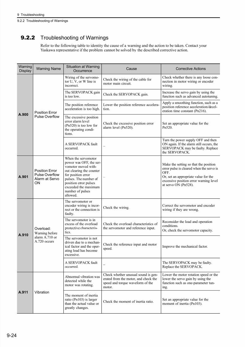
7/17/2019 Manual Yaskawa_servo_drive.pdf
http://slidepdf.com/reader/full/manual-yaskawaservodrivepdf 289/328
9 Troubleshooting
9.2.2 Troubleshooting of Warnings
9-24
9.2.2 Troubleshooting of Warnings
Refer to the following table to identity the cause of a warning and the action to be taken. Contact yourYaskawa representative if the problem cannot be solved by the described corrective action.
WarningDisplay
Warning NameSituation at Warning
OccurrenceCause Corrective Actions
A.900Position ErrorPulse Overflow
Wiring of the servomo-tor U, V, or W line isincorrect.
Check the wiring of the cable formotor main circuit.
Check whether there is any loose con-nection in motor wiring or encoderwiring.
The SERVOPACK gainis too low.
Check the SERVOPACK gain.Increase the servo gain by using thefunction such as advanced autotuning.
The position referenceacceleration is too high.
Lower the position reference accelera-tion.
Apply a smoothing function, such as a position reference acceleration/decel-eration time constant (Pn216).
The excessive position
error alarm level(Pn520) is too low forthe operating condi-tions.
Check the excessive position erroralarm level (Pn520).
Set an appropriate value for thePn520.
A SERVOPACK faultoccurred.
−
Turn the power supply OFF and thenON again. If the alarm still occurs, theSERVOPACK may be faulty. Replacethe SERVOPACK.
A.901
Position ErrorPulse Overflow Alarm at Servo
ON
When the servomotor power was OFF, the ser-vomotor moved with-out clearing the counterfor position error pulses. The number of
position error pulsesexceeded the maximumnumber of pulsesallowed.
–
Make the setting so that the positionerror pulse is cleared when the servo isOFF.Or, set an appropriate value for the
excessive position error warning levelat servo ON (Pn528).
A.910
Overload:
Warning beforealarm A.710 or
A.720 occurs
The servomotor orencoder wiring is incor-rect or the connection isfaulty.
Check the wiring.Correct the servomotor and encoderwiring if they are wrong.
The servomotor is inexcess of the overload protective characteris-tics.
Check the overload characteristics ofthe servomotor and reference input.
Reconsider the load and operationconditions.
Or, check the servomotor capacity.
The servomotor is not
driven due to a mechan-ical factor and the oper-ating load has becomeexcessive.
Check the reference input and motorspeed.
Improve the mechanical factor.
A SERVOPACK faultoccurred.
− The SERVOPACK may be faulty.Replace the SERVOPACK.
A.911 Vibration
Abnormal vibration wasdetected while themotor was rotating.
Check whether unusual sound is gen-erated from the motor, and check thespeed and torque waveform of themotor.
Lower the motor rotation speed or thelower the servo gain by using thefunction such as one-parameter tun-ing.
The moment of inertiaratio (Pn103) is larger
than the actual value orgreatly changes.
Check the moment of inertia ratio.Set an appropriate value for the
moment of inertia (Pn103).
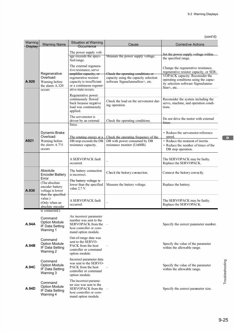
7/17/2019 Manual Yaskawa_servo_drive.pdf
http://slidepdf.com/reader/full/manual-yaskawaservodrivepdf 290/328
9.2 Warning Displays
9-25
T r o u b l e s h o o t i n g
A.920
RegenerativeOverload:
Warning beforethe alarm A.320occurs
The power supply volt-
age exceeds the speci-fied range. Measure the power supply voltage.
Set the power supply voltage within
the specified range.
The external regenera-tive resistance, servoamplifier capacity, orregenerative resistorcapacity is insufficientor a continuous regener-ative state occurs.
Check the operating conditions orcapacity using the capacity selectionsoftware SigmaJunmaSize+, etc.
Change the regenerative resistance,regenerative resistor capacity, or SER-VOPACK capacity. Reconsider theoperating conditions using the capac-ity selection software SigmaJunma-Size+, etc.
Regenerative powercontinuously flowed back because negativeload was continuouslyapplied.
Check the load on the servomotor dur-ing operation.
Reconsider the system including theservo, machine, and operation condi-tions.
A921
Dynamic BrakeOverload:
Warning beforethe alarm A.731occurs
The servomotor isdriven by an externalforce.
Check the operating conditions.Do not drive the motor with externalforce.
The rotating energy at aDB stop exceeds the DBresistance capacity.
Check the operating frequency of theDB with power consumed by DBresistance monitor (Un00B).
• Reduce the servomotor referencespeed.
• Reduce the moment of inertia.
• Reduce the number of times of theDB stop operation.
A SERVOPACK faultoccurred.
– The SERVOPACK may be faulty.Replace the SERVOPACK.
A.930
Absolute
Encoder BatteryError
(The absoluteencoder batteryvoltage is lowerthan the specifiedvalue.)
(Only when anabsolute encoderis connected.)
The battery connection
is incorrect. Check the battery connection. Connect the battery correctly.
The battery voltage islower than the specifiedvalue 2.7 V.
Measure the battery voltage. Replace the battery.
A SERVOPACK faultoccurred.
– The SERVOPACK may be faulty.Replace the SERVOPACK.
A.94A
CommandOption ModuleIF Data SettingWarning 1
An incorrect parameternumber was sent to theSERVOPACK from thehost controller or com-
mand option module.
– Specify the correct parameter number.
A.94B
CommandOption ModuleIF Data SettingWarning 2
Out-of-range data wassent to the SERVO-PACK from the hostcontroller or commandoption module.
– Specify the value of the parameterwithin the allowable range.
A.94C
CommandOption ModuleIF Data SettingWarning 3
Incorrect parameter datawas sent to the SERVO-PACK from the hostcontroller or commandoption module.
– Specify the value of the parameterwithin the allowable range.
A.94D
CommandOption Module
IF Data SettingWarning 4
The incorrect parame-ter size was sent to the
SERVOPACK from thehost controller or com-mand option module.
– Specify the correct parameter size.
(cont’d)
WarningDisplay
Warning NameSituation at Warning
OccurrenceCause Corrective Actions
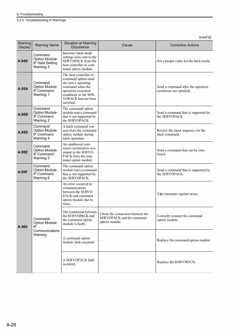
7/17/2019 Manual Yaskawa_servo_drive.pdf
http://slidepdf.com/reader/full/manual-yaskawaservodrivepdf 291/328
9 Troubleshooting
9.2.2 Troubleshooting of Warnings
9-26
A.94E
Command
Option ModuleIF Data SettingWarning 5
Incorrect latch mode
settings were sent to theSERVOPACK from thehost controller or com-mand option module.
– Set a proper value for the latch mode.
A.95A
CommandOption ModuleIF CommandWarning 1
The host controller orcommand option mod-ule sent a operatingcommand when theoperation executionconditions in the SER-VOPACK had not beensatisfied.
– Send a command after the operationconditions are satisfied.
A.95B
CommandOption Module
IF CommandWarning 2
The command optionmodule sent a command
that is not supported bythe SERVOPACK.
– Send a command that is supported by
the SERVOPACK.
A.95D
CommandOption ModuleIF CommandWarning 4
A latch command wassent from the commandoption module duringlatch operation.
– Review the input sequence for thelatch command.
A.95E
CommandOption ModuleIF CommandWarning 5
An unallowed com-mand combination wasoutput to the SERVO-PACK from the com-mand option module.
– Send a command that can be com- bined.
A.95F
CommandOption ModuleIF CommandWarning 6
The command optionmodule sent a commandthat is not supported bythe SERVOPACK.
– Send a command that is supported bythe SERVOPACK.
A.960
CommandOption ModuleIFCommunications
Warning
An error occurred incommunications between the SERVO-PACK and commandoption module due tonoise.
– Take measures against noise.
The connection betweenthe SERVOPACK andthe command optionmodule is faulty.
Check the connection between theSERVOPACK and the commandoption module.
Correctly connect the commandoption module.
A command optionmodule fault occurred.
– Replace the command option module.
A SERVOPACK faultoccurred.
– Replace the SERVOPACK.
(cont’d)
WarningDisplay
Warning NameSituation at Warning
OccurrenceCause Corrective Actions
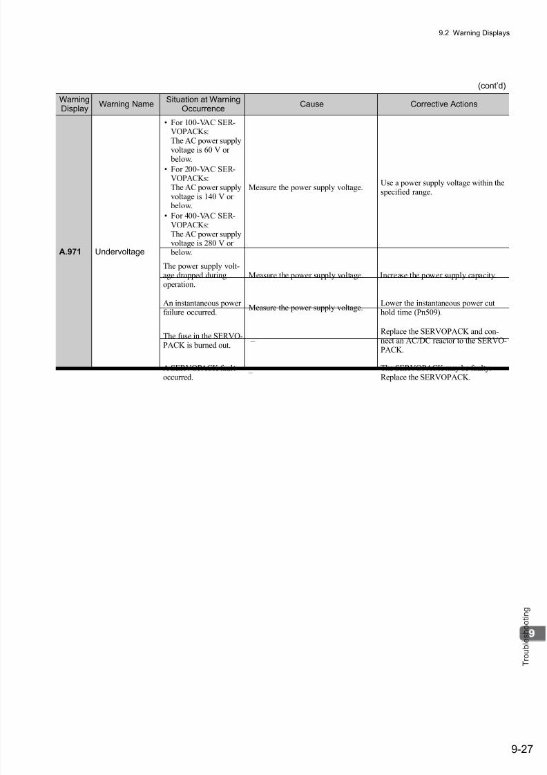
7/17/2019 Manual Yaskawa_servo_drive.pdf
http://slidepdf.com/reader/full/manual-yaskawaservodrivepdf 292/328
9.2 Warning Displays
9-27
T r o u b l e s h o o t i n g
A.971 Undervoltage
• For 100-VAC SER-
VOPACKs:The AC power supplyvoltage is 60 V or below.
• For 200-VAC SER-VOPACKs:The AC power supplyvoltage is 140 V or below.
• For 400-VAC SER-VOPACKs:The AC power supplyvoltage is 280 V or below.
Measure the power supply voltage.Use a power supply voltage within thespecified range.
The power supply volt-age dropped duringoperation.
Measure the power supply voltage. Increase the power supply capacity.
An instantaneous powerfailure occurred.
Measure the power supply voltage.Lower the instantaneous power cuthold time (Pn509).
The fuse in the SERVO-PACK is burned out.
– Replace the SERVOPACK and con-nect an AC/DC reactor to the SERVO-PACK.
A SERVOPACK faultoccurred.
– The SERVOPACK may be faulty.Replace the SERVOPACK.
(cont’d)
WarningDisplay
Warning NameSituation at Warning
OccurrenceCause Corrective Actions
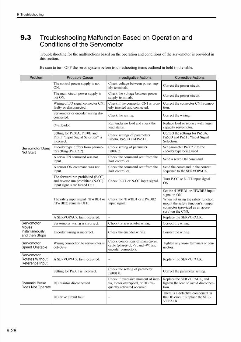
7/17/2019 Manual Yaskawa_servo_drive.pdf
http://slidepdf.com/reader/full/manual-yaskawaservodrivepdf 293/328
9 Troubleshooting
9-28
9.3 Troubleshooting Malfunction Based on Operation andConditions of the Servomotor
Troubleshooting for the malfunctions based on the operation and conditions of the servomotor is provided in
this section.
Be sure to turn OFF the servo system before troubleshooting items outlined in bold in the table.
Problem Probable Cause Investigative Actions Corrective Actions
Servomotor DoesNot Start
The control power supply is notON.
Check voltage between power sup- ply terminals.
Correct the power circuit.
The main circuit power supply isnot ON.
Check the voltage between powersupply terminals.
Correct the power circuit.
Wiring of I/O signal connector CN1faulty or disconnected.
Check if the connector CN1 is prop-erly inserted and connected.
Correct the connector CN1 connec-tion.
Servomotor or encoder wiring dis-connected.
Check the wiring. Correct the wiring.
OverloadedRun under no load and check theload status.
Reduce load or replace with largercapacity servomotor.
Setting for Pn50A, Pn50B andPn511 “Input Signal Selection” isincorrect.
Check settings of parametersPn50A, Pn50B and Pn511.
Correct the settings for Pn50A,Pn50B and Pn511 “Input SignalSelection.”
Encoder type differs from parame-ter setting (Pn002.2).
Check setting of parameterPn002.2.
Set parameter Pn002.2 to theencoder type being used.
A servo ON command was notinput.
Check the command sent from thehost controller.
Send a servo ON command.
A sensor ON command was notinput.
Check the command sent from thehost controller.
Send the command in the correctsequence to the SERVOPACK.
The forward run prohibited (P-OT)
and reverse run prohibited (N-OT)input signals are turned OFF.
Check P-OT or N-OT input signal. Turn P-OT or N-OT input signalON.
The safety input signal (/HWBB1 or/HWBB2) remains OFF.
Check the /HWBB1 or /HWBB2input signal.
Set the /HWBB1 or /HWBB2 inputsignal to ON.
When not using the safety function,mount the safety function’s jumperconnector (provided as an acces-sory) on the CN8.
A SERVOPACK fault occurred. – Replace the SERVOPACK.
ServomotorMovesInstantaneously,and then Stops
Servomotor wiring is incorrect. Check the servomotor wiring. Correct the wiring.
Encoder wiring is incorrect. Check the encoder wiring. Correct the wiring.
ServomotorSpeed Unstable
Wiring connection to servomotor isdefective.
Check connections of main circuitcable (phases-U, -V, and -W) andencoder connectors.
Tighten any loose terminals or con-nectors.
ServomotorRotates WithoutReference Input
A SERVOPACK fault occurred. – Replace the SERVOPACK.
Dynamic BrakeDoes Not Operate
Setting for Pn001 is incorrect.Check the setting of parameterPn001.0.
Correct the parameter setting.
DB resistor disconnectedCheck if excessive moment of iner-tia, motor overspeed, or DB fre-quently activated occurred.
Replace the SERVOPACK, andlighten the load to avoid disconnec-tion.
DB drive circuit fault – There is a defective component inthe DB circuit. Replace the SER-VOPACK.
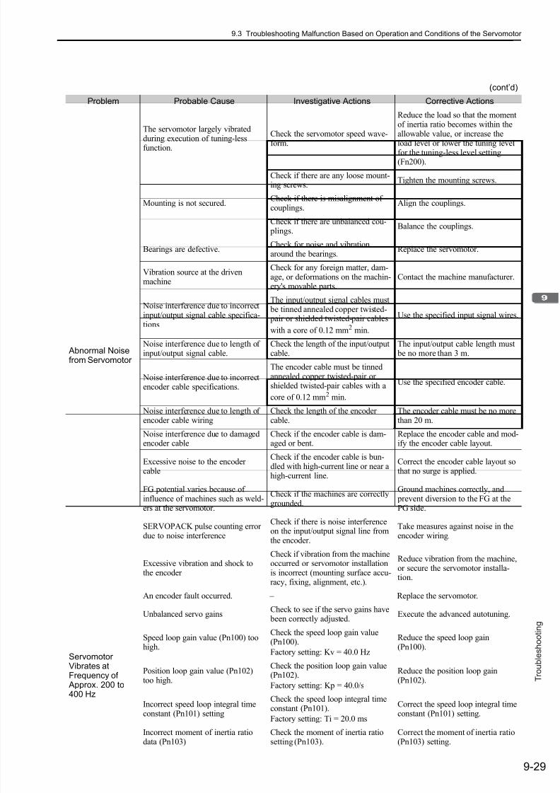
7/17/2019 Manual Yaskawa_servo_drive.pdf
http://slidepdf.com/reader/full/manual-yaskawaservodrivepdf 294/328
9.3 Troubleshooting Malfunction Based on Operation and Conditions of the Servomotor
9-29
T r o u b l e s h o o t i n g
Abnormal Noisefrom Servomotor
The servomotor largely vibrated
during execution of tuning-lessfunction.
Check the servomotor speed wave-form.
Reduce the load so that the momentof inertia ratio becomes within theallowable value, or increase theload level or lower the tuning levelfor the tuning-less level setting(Fn200).
Mounting is not secured.
Check if there are any loose mount-ing screws.
Tighten the mounting screws.
Check if there is misalignment ofcouplings.
Align the couplings.
Check if there are unbalanced cou- plings.
Balance the couplings.
Bearings are defective.Check for noise and vibrationaround the bearings.
Replace the servomotor.
Vibration source at the drivenmachine
Check for any foreign matter, dam-
age, or deformations on the machin-ery's movable parts.
Contact the machine manufacturer.
Noise interference due to incorrectinput/output signal cable specifica-tions
The input/output signal cables must be tinned annealed copper twisted- pair or shielded twisted-pair cables
with a core of 0.12 mm2 min.
Use the specified input signal wires.
Noise interference due to length ofinput/output signal cable.
Check the length of the input/outputcable.
The input/output cable length must be no more than 3 m.
Noise interference due to incorrectencoder cable specifications.
The encoder cable must be tinnedannealed copper twisted-pair orshielded twisted-pair cables with a
core of 0.12 mm2 min.
Use the specified encoder cable.
Noise interference due to length ofencoder cable wiring
Check the length of the encodercable.
The encoder cable must be no morethan 20 m.
Noise interference due to damagedencoder cable
Check if the encoder cable is dam-aged or bent.
Replace the encoder cable and mod-ify the encoder cable layout.
Excessive noise to the encodercable
Check if the encoder cable is bun-dled with high-current line or near ahigh-current line.
Correct the encoder cable layout sothat no surge is applied.
FG potential varies because ofinfluence of machines such as weld-ers at the servomotor.
Check if the machines are correctlygrounded.
Ground machines correctly, and prevent diversion to the FG at thePG side.
SERVOPACK pulse counting errordue to noise interference
Check if there is noise interferenceon the input/output signal line fromthe encoder.
Take measures against noise in theencoder wiring.
Excessive vibration and shock tothe encoder
Check if vibration from the machineoccurred or servomotor installationis incorrect (mounting surface accu-racy, fixing, alignment, etc.).
Reduce vibration from the machine,or secure the servomotor installa-tion.
An encoder fault occurred. – Replace the servomotor.
ServomotorVibrates atFrequency of Approx. 200 to
400 Hz
Unbalanced servo gainsCheck to see if the servo gains have been correctly adjusted.
Execute the advanced autotuning.
Speed loop gain value (Pn100) toohigh.
Check the speed loop gain value(Pn100).
Factory setting: Kv = 40.0 Hz
Reduce the speed loop gain(Pn100).
Position loop gain value (Pn102)too high.
Check the position loop gain value(Pn102).
Factory setting: Kp = 40.0/s
Reduce the position loop gain(Pn102).
Incorrect speed loop integral timeconstant (Pn101) setting
Check the speed loop integral timeconstant (Pn101).
Factory setting: Ti = 20.0 ms
Correct the speed loop integral timeconstant (Pn101) setting.
Incorrect moment of inertia ratiodata (Pn103)
Check the moment of inertia ratiosetting (Pn103).
Correct the moment of inertia ratio(Pn103) setting.
(cont’d)
Problem Probable Cause Investigative Actions Corrective Actions
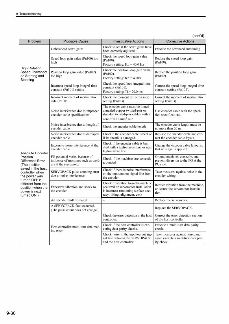
7/17/2019 Manual Yaskawa_servo_drive.pdf
http://slidepdf.com/reader/full/manual-yaskawaservodrivepdf 295/328
9 Troubleshooting
9-30
High RotationSpeed Overshooton Starting andStopping
Unbalanced servo gainsCheck to see if the servo gains have been correctly adjusted.
Execute the advanced autotuning.
Speed loop gain value (Pn100) toohigh
Check the speed loop gain value(Pn100).
Factory setting: Kv = 40.0 Hz
Reduce the speed loop gain(Pn100).
Position loop gain value (Pn102)too high
Check the position loop gain value(Pn102).
Factory setting: Kp = 40.0/s
Reduce the position loop gain(Pn102).
Incorrect speed loop integral timeconstant (Pn101) setting
Check the speed loop integral timeconstant (Pn101).
Factory setting: Ti = 20.0 ms
Correct the speed loop integral timeconstant setting (Pn101).
Incorrect moment of inertia ratiodata (Pn103)
Check the moment of inertia ratiosetting (Pn103).
Correct the moment of inertia ratiosetting (Pn103).
Absolute EncoderPositionDifference Error(The position
saved in the hostcontroller whenthe power wasturned OFF isdifferent from theposition when thepower is nextturned ON.)
Noise interference due to improperencoder cable specifications
The encoder cable must be tinnedannealed copper twisted-pair or
shielded twisted-pair cables with a
core of 0.12 mm2 min.
Use encoder cable with the speci-fied specifications.
Noise interference due to length ofencoder cable.
Check the encoder cable length.The encoder cable length must beno more than 20 m.
Noise interference due to damagedencoder cable
Check if the encoder cable is bent orif its sheath is damaged.
Replace the encoder cable and cor-rect the encoder cable layout.
Excessive noise interference at theencoder cable
Check if the encoder cable is bun-dled with a high-current line or nearhigh-current line.
Change the encoder cable layout sothat no surge is applied.
FG potential varies because ofinfluence of machines such as weld-ers at the servomotor.
Check if the machines are correctlygrounded.
Ground machines correctly, and prevent diversion to the FG at thePG side.
SERVOPACK pulse counting errordue to noise interference
Check if there is noise interferenceon the input/output signal line fromthe encoder.
Take measures against noise in theencoder wiring.
Excessive vibration and shock tothe encoder
Check if vibration from the machineoccurred or servomotor installationis incorrect (mounting surface accu-racy, fixing, alignment, etc.).
Reduce vibration from the machine,or secure the servomotor installa-tion.
An encoder fault occurred. – Replace the servomotor.
A SERVOPACK fault occurred.
(The pulse count does not change.) – Replace the SERVOPACK.
Host controller multi-turn data read-ing error
Check the error detection at the hostcontroller.
Correct the error detection sectionof the host controller.
Check if the host controller is exe-cuting data parity checks.
Execute a multi-turn data paritycheck.
Check noise in the input/output sig-nal line between the SERVOPACKand the host controller.
Take measures against noise, andagain execute a multiturn data par-ity check.
(cont’d)
Problem Probable Cause Investigative Actions Corrective Actions
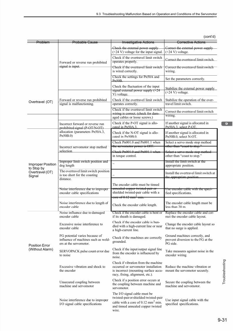
7/17/2019 Manual Yaskawa_servo_drive.pdf
http://slidepdf.com/reader/full/manual-yaskawaservodrivepdf 296/328
9.3 Troubleshooting Malfunction Based on Operation and Conditions of the Servomotor
9-31
T r o u b l e s h o o t i n g
Overtravel (OT)
Forward or reverse run prohibitedsignal is input.
Check the external power supply(+24 V) voltage for the input signal.
Correct the external power supply(+24 V) voltage.
Check if the overtravel limit switchoperates properly.
Correct the overtravel limit switch.
Check if the overtravel limit switchis wired correctly.
Correct the overtravel limit switchwiring.
Check the settings for Pn50A andPn50B.
Set the parameters correctly.
Forward or reverse run prohibitedsignal is malfunctioning.
Check the fluctuation of the inputsignal external power supply (+24V) voltage.
Stabilize the external power supply(+24 V) voltage.
Check if the overtravel limit switchoperates correctly.
Stabilize the operation of the over-travel limit switch.
Check if the overtravel limit switchwiring is correct. (check for dam-aged cables or loose screws.)
Correct the overtravel limit switch
wiring.
Incorrect forward or reverse run prohibited signal (P-OT/N-OT)allocation (parameters Pn50A.3,Pn50B.0)
Check if the P-OT signal is allo-cated in Pn50A.3.
If another signal is allocated inPn50A.3, select P-OT.
Check if the N-OT signal is allo-cated in Pn50B.0.
If another signal is allocated inPn50B.0, select N-OT.
Incorrect servomotor stop methodselection
Check Pn001.0 and Pn001.1 whenthe servomotor power is OFF.
Select a servo mode stop methodother than “coast to stop.”
Check Pn001.0 and Pn001.1 whenin torque control.
Select a servo mode stop methodother than “coast to stop.”
Improper Positionto Stop by
Overtravel (OT)Signal
Improper limit switch position anddog length
− Install the limit switch at theappropriate position.
The overtravel limit switch position
is too short for the coastingdistance.
− Install the overtravel limit switch atthe appropriate position.
Position Error(Without Alarm)
Noise interference due to improperencoder cable specifications
The encoder cable must be tinnedannealed copper twisted-pair orshielded twisted-pair cable with a
core of 0.12 mm2 min.
Use encoder cable with the speci-fied specifications.
Noise interference due to length ofencoder cable
Check the encoder cable length.The encoder cable length must beless than 20 m.
Noise influence due to damagedencoder cable
Check if the encoder cable is bent orif its sheath is damaged.
Replace the encoder cable and cor-rect the encoder cable layout.
Excessive noise interference toencoder cable
Check if the encoder cable is bun-dled with a high-current line or neara high-current line.
Change the encoder cable layout sothat no surge is applied.
FG potential varies because ofinfluence of machines such as weld-ers at the servomotor.
Check if the machines are correctlygrounded.
Ground machines correctly, and prevent diversion to the FG at thePG side.
SERVOPACK pulse count error dueto noise
Check if the input/output signal linefrom the encoder is influenced bynoise.
Take measures against noise in theencoder wiring.
Excessive vibration and shock tothe encoder
Check if vibration from the machineoccurred or servomotor installationis incorrect (mounting surface accu-racy, fixing, alignment, etc.).
Reduce the machine vibration ormount the servomotor securely.
Unsecured coupling betweenmachine and servomotor
Check if a position error occurs atthe coupling between machine andservomotor.
Secure the coupling between themachine and servomotor.
Noise interference due to improperI/O signal cable specifications
The I/O signal cable must betwisted-pair or shielded twisted-pair
cable with a core of 0.12 mm2 min.and tinned annealed copper twistedwire.
Use input signal cable with thespecified specifications.
(cont’d)
Problem Probable Cause Investigative Actions Corrective Actions
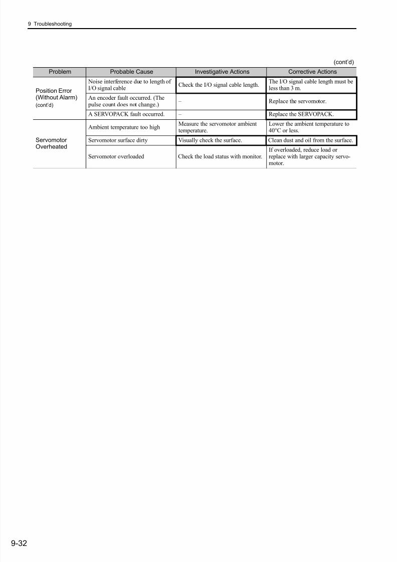
7/17/2019 Manual Yaskawa_servo_drive.pdf
http://slidepdf.com/reader/full/manual-yaskawaservodrivepdf 297/328
9 Troubleshooting
9-32
Position Error
(Without Alarm)(cont’d)
Noise interference due to length ofI/O signal cable
Check the I/O signal cable length.The I/O signal cable length must beless than 3 m.
An encoder fault occurred. (The pulse count does not change.)
– Replace the servomotor.
A SERVOPACK fault occurred. – Replace the SERVOPACK.
ServomotorOverheated
Ambient temperature too highMeasure the servomotor ambienttemperature.
Lower the ambient temperature to40°C or less.
Servomotor surface dirty Visually check the surface. Clean dust and oil from the surface.
Servomotor overloaded Check the load status with monitor.If overloaded, reduce load orreplace with larger capacity servo-motor.
(cont’d)
Problem Probable Cause Investigative Actions Corrective Actions

7/17/2019 Manual Yaskawa_servo_drive.pdf
http://slidepdf.com/reader/full/manual-yaskawaservodrivepdf 298/32810-1
A p p
e n d i x
10
Appendix
10.1 List of Parameters . . . . . . . . . . . . . . . . . . . . . . . . . . . . . . . . . . . . . . . . . 10-2
10.1.1 Utility Functions . . . . . . . . . . . . . . . . . . . . . . . . . . . . . . . . . . . . . . . . . . . . . . . . . . . . 10-2
10.1.2 Parameters . . . . . . . . . . . . . . . . . . . . . . . . . . . . . . . . . . . . . . . . . . . . . . . . . . . . . . . 10-3
10.2 Monitor Modes . . . . . . . . . . . . . . . . . . . . . . . . . . . . . . . . . . . . . . . . . .10-22
10.3 Parameter Recording Table . . . . . . . . . . . . . . . . . . . . . . . . . . . . . . . .10-23
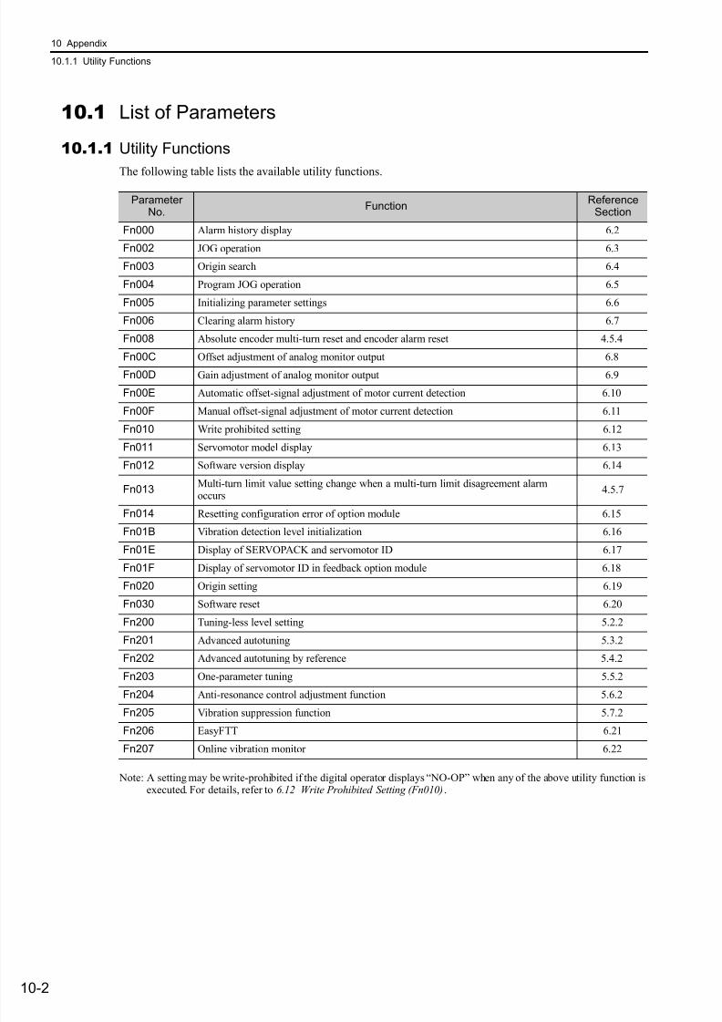
7/17/2019 Manual Yaskawa_servo_drive.pdf
http://slidepdf.com/reader/full/manual-yaskawaservodrivepdf 299/328

7/17/2019 Manual Yaskawa_servo_drive.pdf
http://slidepdf.com/reader/full/manual-yaskawaservodrivepdf 300/328
10.1 List of Parameters
10-3
A p p
e n d i x
10.1.2 Parameters
ParameterNo.
NameSettingRange
UnitsFactorySetting
WhenEnabled
ClassificationReference
Section
Pn000
Basic Function Select Switch 0 0000 to 00B3 − 0000 After restart Setup −
Pn001
Application Function Select Switch 1 0000 to 1122 − 0000 After restart Setup −
0
1
2 to 3
Forward reference for forward rotation.
Forward reference for reverse rotation. (Reverse rotation mode)
Reserved (Do not change.)
Direction Selection
4thdigit
3rddigit
2nddigit
1stdigit
n.
Reserved (Do not change.)
Reserved (Do not change.)
Reserved (Do not change.)
(Refer to 4.2.2)
0
1
2
Stops the motor by applying DB (dynamic brake).
Stops the motor by applying dynamic brake (DB) and then releases DB.
Makes the motor coast to a stop state without using the dynamic brake (DB).
0
1
2
Same setting as Pn001.0 (Stops the motor by applying DB or by coasting).
Sets the torque of Pn406 to the maximum value, decelerate the servomotor to a stop,
and then sets it to servolock state.
Sets the torque of Pn406 to the maximum value, decelerates the servomotor to a stop,
and then sets it to coasting state.
Overtravel (OT) Stop Mode
4thdigit
3rddigit
2nddigit
1stdigit
n.
0
1
Not applicable to DC power input: Input AC power supply through L1, L2 (, and L3) terminals.
Applicable to DC power input: Input DC power supply between B1/ + and, or input
DC power supply between B1 and
2.
AC/DC Power Input Selection
Reserved (Do not change.)
Servomotor power OFF or Alarm Gr.1 Stop Mode (Refer to 4.2.8)
(Refer to 4.2.3)
(Refer to 3.1.4)

7/17/2019 Manual Yaskawa_servo_drive.pdf
http://slidepdf.com/reader/full/manual-yaskawaservodrivepdf 301/328
10 Appendix
10.1.2 Parameters
10-4
Pn002
Application Function Select Switch 2 0000 to 4113 − 0000 After restart Setup −
Pn006
Application Function Select Switch 6 0000 to 005F − 0002 Immediately Setup −
∗1. For details on this function, refer to the manual of the connected command option module.
(cont’d)
ParameterNo.
NameSettingRange
UnitsFactorySetting
WhenEnabled
ClassificationReference
Section
0
1
2
Disables the torque limit reference from the command option module.
Enables the torque limit reference from the command option module.
Reserved (Do not change.)
Torque Limit Reference Selection for Command Option Module*1
4th
digit
3rd
digit
2nd
digit1stdigit
n.
0
1
Disables the speed limit reference when torque limit is used from the command option module.
Enables the speed limit reference when torque limit is used from the command option module.
Speed Limit Reference Selection for Command Option Module*1
0
1
Uses absolute encoder as an absolute encoder.
Uses absolute encoder as an incremental encoder.
Absolute Encoder Usage
0
1
2
3
4
Do not use external encoder.
Uses external encoder in forward rotation direction.
Reserved (Do not change.)
Uses external encoder in reversed rotation direction.
Reserved (Do not change.)
External Encoder Usage
Enables torque limit reference from the command option module when external input signalsP-CL and N-CL are enabled.3
(Refer to 4.5)
(Refer to 8.3.1)
00
01
02
03
04
05
06
07
08
09
0A
0B
0C
0D
Motor speed (1 V/1000 min-1)
Speed reference (1 V/1000 min-1)
Torque reference (1 V/100%)
Position error (0.05 V/1 reference unit)
Position amplifier error (after electronic gears) (0.05 V/ 1 encoder pulse unit)
Position reference speed (1 V/1000 min-1)
Reserved (Do not change.)
Motor-load position error (0.01 V/1 reference unit)
Positioning completion (positioning completed: 5 V, positioning not completed: 0 V)
Speed feedforward (1 V/1000 min-1)
Torque feedforward (1 V/100%)
Active gain (1st gain: 1 V, 2nd gain: 2 V)
Completion of position reference (completed: 5 V, not completed: 0 V)
External encoder speed (1 V/1000 min-1)
Analog Monitor 1 Signal Selection
4thdigit
3rddigit
2nddigit
1stdigit
n.
Reserved (Do not change.)
Reserved (Do not change.)
(Refer to 5.1.3)
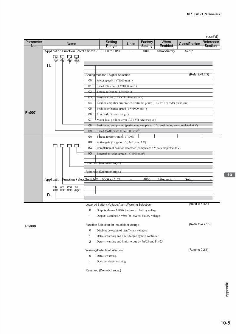
7/17/2019 Manual Yaskawa_servo_drive.pdf
http://slidepdf.com/reader/full/manual-yaskawaservodrivepdf 302/328
10.1 List of Parameters
10-5
A p p
e n d i x
Pn007
Application Function Select Switch 7 0000 to 005F − 0000 Immediately Setup −
Pn008
Application Function Select Switch 8 0000 to 7121 − 4000 After restart Setup −
(cont’d)
ParameterNo.
NameSettingRange
UnitsFactorySetting
WhenEnabled
ClassificationReference
Section
4thdigit 3rddigit 2nddigit 1stdigit
n.
Reserved (Do not change.)
Reserved (Do not change.)
00
01
02
03
04
05
06
07
08
09
0A
0B
0C
0D
Motor speed (1 V/1000 min-1)
Speed reference (1 V/1000 min-1)
Torque reference (1 V/100%)
Position error (0.05 V/1 reference unit)
Position amplifier error (after electronic gears) (0.05 V/ 1 encoder pulse unit)
Position reference speed (1 V/1000 min-1)
Reserved (Do not change.)
Motor-load position error (0.01 V/1 reference unit)
Positioning completion (positioning completed: 5 V, positioning not completed: 0 V)
Speed feedforward (1 V/1000 min-1)
Torque feedforward (1 V/100%)
Active gain (1st gain: 1 V, 2nd gain: 2 V)
Completion of position reference (completed: 5 V not completed: 0 V)
External encoder speed (1 V/1000 min-1)
Analog Monitor 2 Signal Selection (Refer to 5.1.3)
0
1
Outputs alarm (A.830) for lowered battery voltage.
Outputs warning (A.930) for lowered battery voltage.
Lowered Battery Voltage Alarm/Warning Selection
0
1
2
Disables detection of insufficient voltages.
Detects warning and limits torque by host controller.
Detects warning and limits torque by Pn424 and Pn425.
Function Selection for Insufficient voltage
4thdigit
3rddigit
2nddigit
1stdigit
n.
0
1
Detects warning.
Does not detect warning.
Warning Detection Selection
Reserved (Do not change.)
(Refer to 4.5.4)
(Refer to 4.2.10)
(Refer to 9.2.1)
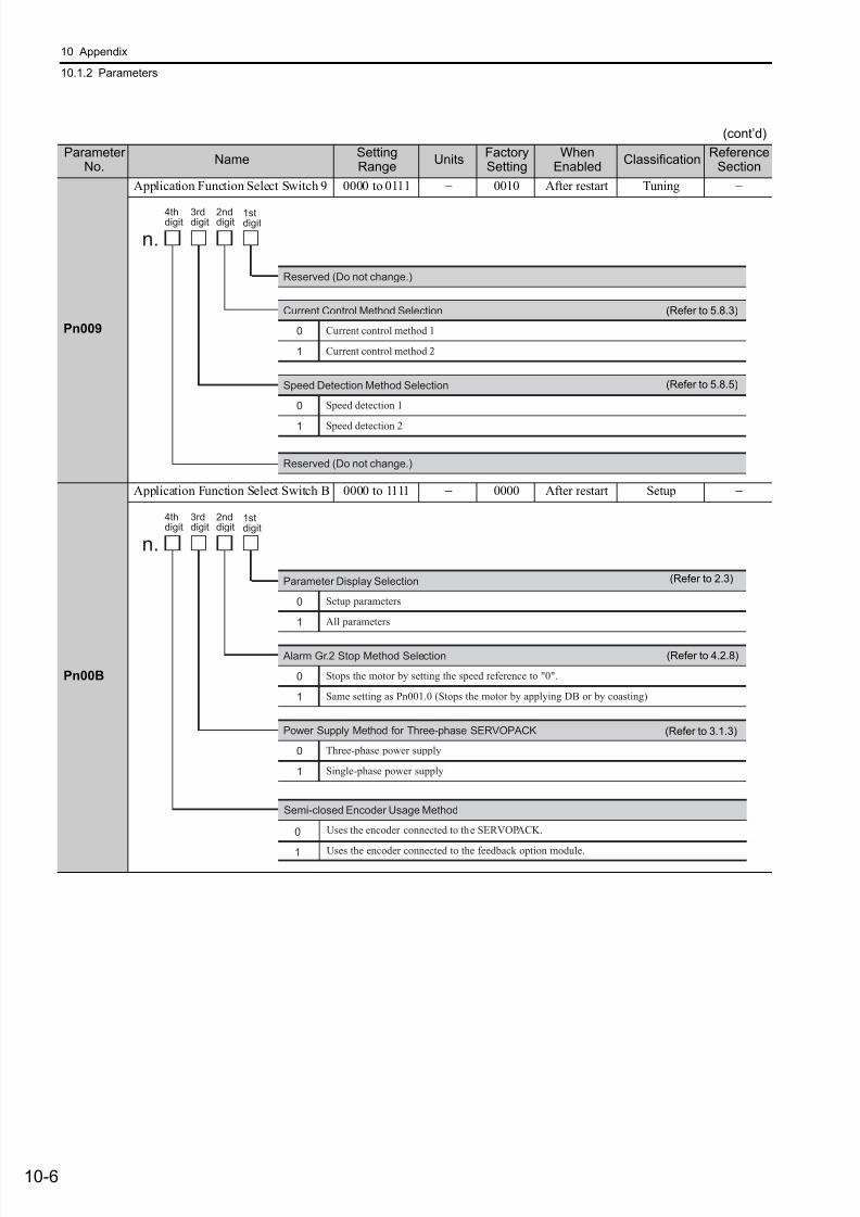
7/17/2019 Manual Yaskawa_servo_drive.pdf
http://slidepdf.com/reader/full/manual-yaskawaservodrivepdf 303/328
10 Appendix
10.1.2 Parameters
10-6
Pn009
Application Function Select Switch 9 0000 to 0111 − 0010 After restart Tuning −
Pn00B
Application Function Select Switch B 0000 to 1111 − 0000 After restart Setup −
(cont’d)
ParameterNo.
NameSettingRange
UnitsFactorySetting
WhenEnabled
ClassificationReference
Section
0
1
Current Control Method Selection
Reserved (Do not change.)
Reserved (Do not change.)
4thdigit
3rddigit
2nddigit
1stdigit
n.
Current control method 1
Current control method 2
0
1
Speed Detection Method Selection
Speed detection 1
Speed detection 2
(Refer to 5.8.3)
(Refer to 5.8.5)
0
1
Alarm Gr.2 Stop Method Selection
4thdigit
3rddigit
2nddigit
1stdigit
n.
Stops the motor by setting the speed reference to "0".
Same setting as Pn001.0 (Stops the motor by applying DB or by coasting)
0
1
Power Supply Method for Three-phase SERVOPACK
Three-phase power supply
Single-phase power supply
0
1
Parameter Display Selection
Setup parameters
All parameters
Semi-closed Encoder Usage Method
Uses the encoder connected to the SERVOPACK.
Uses the encoder connected to the feedback option module.
0
1
(Refer to 2.3)
(Refer to 4.2.8)
(Refer to 3.1.3)
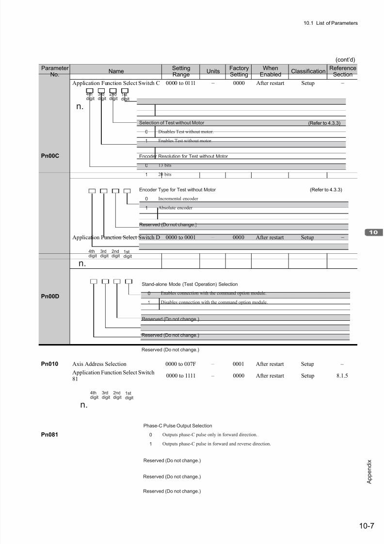
7/17/2019 Manual Yaskawa_servo_drive.pdf
http://slidepdf.com/reader/full/manual-yaskawaservodrivepdf 304/328
10.1 List of Parameters
10-7
A p p
e n d i x
Pn00C
Application Function Select Switch C 0000 to 0111 − 0000 After restart Setup −
Pn00D
Application Function Select Switch D 0000 to 0001 – 0000 After restart Setup −
Pn010 Axis Address Selection 0000 to 007F – 0001 After restart Setup –
Pn081
Application Function Select Switch
81
0000 to 1111 – 0000 After restart Setup 8.1.5
(cont’d)
ParameterNo.
NameSettingRange
UnitsFactorySetting
WhenEnabled
ClassificationReference
Section
0
1
Encoder Resolution for Test without Motor
Reserved (Do not change.)
4thdigit 3rddigit 2nddigit 1stdigit
n.
13 bits
20 bits
0
1
Selection of Test without Motor
Disables Test without motor.
Enables Test without motor.
0
1
Encoder Type for Test without Motor
Incremental encoder
Absolute encoder
(Refer to 4.3.3)
(Refer to 4.3.3)
Reserved (Do not change.)
n.
Reserved (Do not change.)
0
1
Stand-alone Mode (Test Operation) SelectionEnables connection with the command option module.
Disables connection with the command option module.
Reserved (Do not change.)
4thdigit
3rddigit
2nddigit
1stdigit
Reserved (Do not change.)
n.
Reserved (Do not change.)
0
1
Phase-C Pulse Output Selection
Outputs phase-C pulse only in forward direction.
Outputs phase-C pulse in forward and reverse direction.
Reserved (Do not change.)
4thdigit
3rddigit
2nddigit
1stdigit
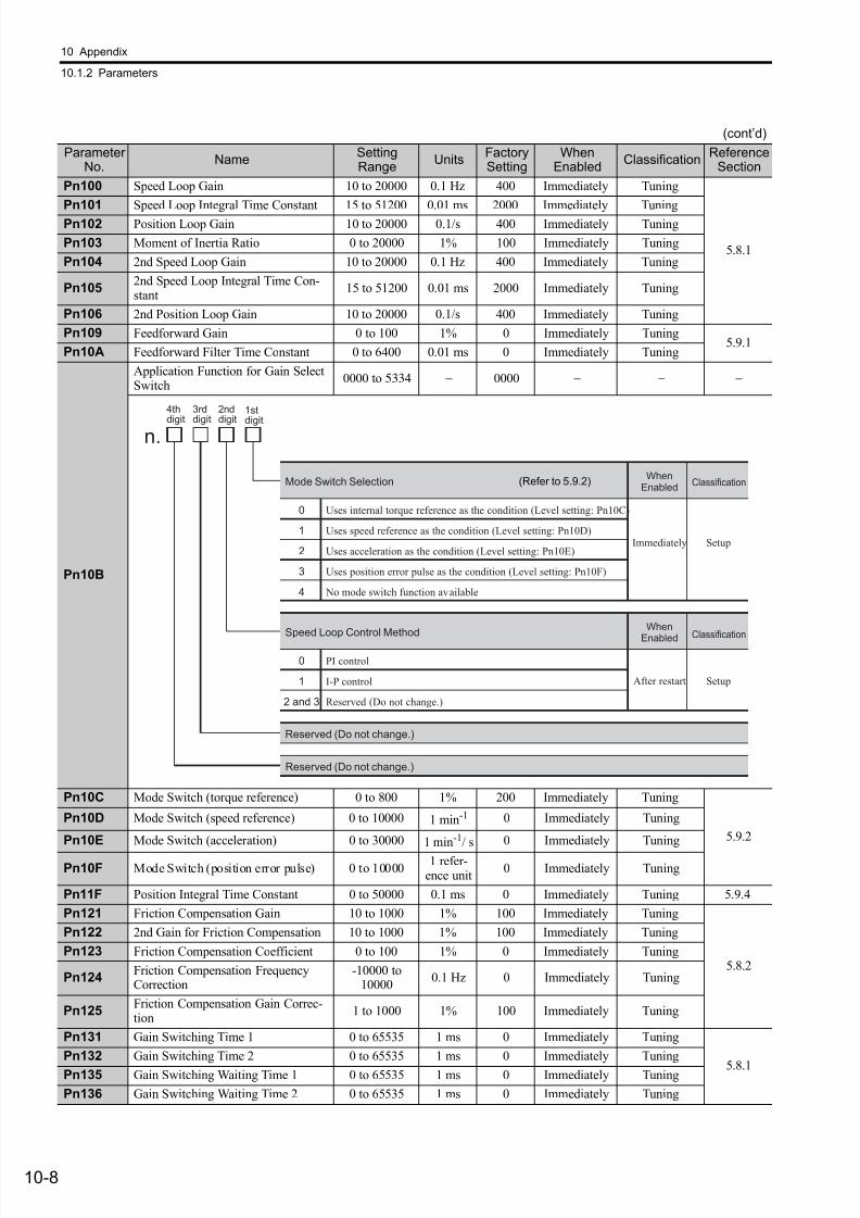
7/17/2019 Manual Yaskawa_servo_drive.pdf
http://slidepdf.com/reader/full/manual-yaskawaservodrivepdf 305/328
10 Appendix
10.1.2 Parameters
10-8
Pn100 Speed Loop Gain 10 to 20000 0.1 Hz 400 Immediately Tuning
5.8.1
Pn101 Speed Loop Integral Time Constant 15 to 51200 0.01 ms 2000 Immediately Tuning
Pn102 Position Loop Gain 10 to 20000 0.1/s 400 Immediately Tuning
Pn103 Moment of Inertia Ratio 0 to 20000 1% 100 Immediately Tuning
Pn104 2nd Speed Loop Gain 10 to 20000 0.1 Hz 400 Immediately Tuning
Pn1052nd Speed Loop Integral Time Con-stant
15 to 51200 0.01 ms 2000 Immediately Tuning
Pn106 2nd Position Loop Gain 10 to 20000 0.1/s 400 Immediately Tuning
Pn109 Feedforward Gain 0 to 100 1% 0 Immediately Tuning5.9.1
Pn10A Feedforward Filter Time Constant 0 to 6400 0.01 ms 0 Immediately Tuning
Pn10B
Application Function for Gain SelectSwitch
0000 to 5334 − 0000 − − −
Pn10C Mode Switch (torque reference) 0 to 800 1% 200 Immediately Tuning
5.9.2
Pn10D Mode Switch (speed reference) 0 to 10000 1 min-1 0 Immediately Tuning
Pn10E Mode Switch (acceleration) 0 to 30000 1 min-1/ s 0 Immediately Tuning
Pn10F Mode Switch (position error pulse) 0 to 100001 refer-
ence unit0 Immediately Tuning
Pn11F Position Integral Time Constant 0 to 50000 0.1 ms 0 Immediately Tuning 5.9.4
Pn121 Friction Compensation Gain 10 to 1000 1% 100 Immediately Tuning
5.8.2
Pn122 2nd Gain for Friction Compensation 10 to 1000 1% 100 Immediately Tuning
Pn123 Friction Compensation Coefficient 0 to 100 1% 0 Immediately Tuning
Pn124Friction Compensation FrequencyCorrection
-10000 to10000
0.1 Hz 0 Immediately Tuning
Pn125Friction Compensation Gain Correc-tion
1 to 1000 1% 100 Immediately Tuning
Pn131 Gain Switching Time 1 0 to 65535 1 ms 0 Immediately Tuning
5.8.1
Pn132 Gain Switching Time 2 0 to 65535 1 ms 0 Immediately Tuning
Pn135 Gain Switching Waiting Time 1 0 to 65535 1 ms 0 Immediately Tuning
Pn136 Gain Switching Waiting Time 2 0 to 65535 1 ms 0 Immediately Tuning
(cont’d)
ParameterNo.
NameSettingRange
UnitsFactorySetting
WhenEnabled
ClassificationReference
Section
0
1
2
3
4
Uses internal torque reference as the condition (Level setting: Pn10C)
Uses speed reference as the condition (Level setting: Pn10D)
Uses acceleration as the condition (Level setting: Pn10E)
Uses position error pulse as the condition (Level setting: Pn10F)
No mode switch function available
Mode Switch Selection
Reserved (Do not change.)
4thdigit
3rddigit
2nddigit
1stdigit
n.
Immediately
WhenEnabled
0
1
2 and 3
PI control
I-P control
Reserved (Do not change.)
Speed Loop Control Method
After restart
When
Enabled
Reserved (Do not change.)
Setup
Classification
Setup
Classification
(Refer to 5.9.2)
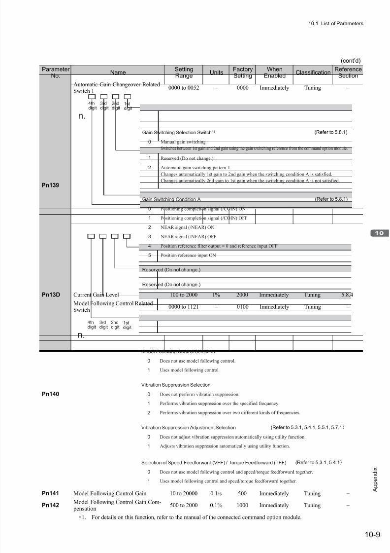
7/17/2019 Manual Yaskawa_servo_drive.pdf
http://slidepdf.com/reader/full/manual-yaskawaservodrivepdf 306/328
10.1 List of Parameters
10-9
A p p
e n d i x
Pn139
Automatic Gain Changeover RelatedSwitch 1
0000 to 0052 − 0000 Immediately Tuning −
Pn13D Current Gain Level 100 to 2000 1% 2000 Immediately Tuning 5.8.4
Pn140
Model Following Control RelatedSwitch
0000 to 1121 − 0100 Immediately Tuning −
Pn141 Model Following Control Gain 10 to 20000 0.1/s 500 Immediately Tuning −
Pn142Model Following Control Gain Com- pensation
500 to 2000 0.1% 1000 Immediately Tuning −
∗1. For details on this function, refer to the manual of the connected command option module.
(cont’d)
ParameterNo.
NameSettingRange
UnitsFactorySetting
WhenEnabled
ClassificationReference
Section
0
1
2
Manual gain switching
Switches between 1st gain and 2nd gain using the gain switching reference from the command option module.
Reserved (Do not change.)
Automatic gain switching pattern 1
Changes automatically 1st gain to 2nd gain when the switching condition A is satisfied.
Changes automatically 2nd gain to 1st gain when the switching condition A is not satisfied.
Gain Switching Selection Switch*1
4thdigit
3rddigit
2nddigit
1stdigit
n.
0
1
2
3
4
5
Positioning completion signal (/COIN) ON
Positioning completion signal (/COIN) OFF
NEAR signal (/NEAR) ON
NEAR signal (/NEAR) OFF
Position reference filter output = 0 and reference input OFF
Position reference input ON
Gain Switching Condition A
Reserved (Do not change.)
Reserved (Do not change.)
(Refer to 5.8.1)
(Refer to 5.8.1)
0
1
Does not use model following control.
Uses model following control.
Model Following Control Selection
4thdigit
3rddigit
2nddigit
1stdigit
n.
0
1
2
Does not perform vibration suppression.
Performs vibration suppression over the specified frequency.
Performs vibration suppression over two different kinds of frequencies.
Vibration Suppression Selection
0
1
Does not use model following control and speed/torque feedforward together.
Uses model following control and speed/torque feedforward together.
Selection of Speed Feedforward (VFF) / Torque Feedforward (TFF)
0
1
Does not adjust vibration suppression automatically using utility function.
Adjusts vibration suppression automatically using utility function.
Vibration Suppression Adjustment Selection (Refer to 5.3.1, 5.4.1, 5.5.1, 5.7.1)
(Refer to 5.3.1, 5.4.1)
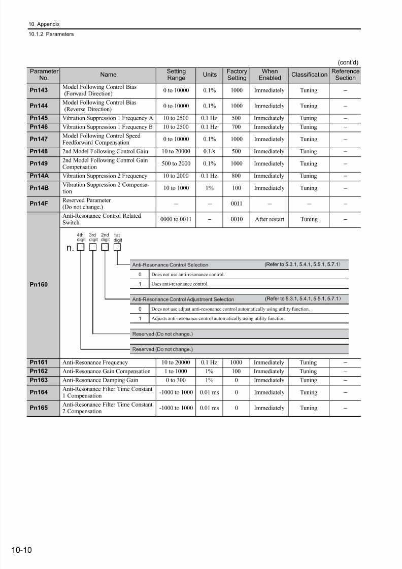
7/17/2019 Manual Yaskawa_servo_drive.pdf
http://slidepdf.com/reader/full/manual-yaskawaservodrivepdf 307/328
10 Appendix
10.1.2 Parameters
10-10
Pn143Model Following Control Bias (Forward Direction)
0 to 10000 0.1% 1000 Immediately Tuning −
Pn144Model Following Control Bias (Reverse Direction)
0 to 10000 0.1% 1000 Immediately Tuning −
Pn145 Vibration Suppression 1 Frequency A 10 to 2500 0.1 Hz 500 Immediately Tuning −
Pn146 Vibration Suppression 1 Frequency B 10 to 2500 0.1 Hz 700 Immediately Tuning −
Pn147Model Following Control SpeedFeedforward Compensation
0 to 10000 0.1% 1000 Immediately Tuning −
Pn148 2nd Model Following Control Gain 10 to 20000 0.1/s 500 Immediately Tuning −
Pn1492nd Model Following Control GainCompensation
500 to 2000 0.1% 1000 Immediately Tuning −
Pn14A Vibration Suppression 2 Frequency 10 to 2000 0.1 Hz 800 Immediately Tuning −
Pn14BVibration Suppression 2 Compensa-tion
10 to 1000 1% 100 Immediately Tuning −
Pn14F Reserved Parameter (Do not change.) - - 0011 - - –
Pn160
Anti-Resonance Control RelatedSwitch
0000 to 0011 − 0010 After restart Tuning −
Pn161 Anti-Resonance Frequency 10 to 20000 0.1 Hz 1000 Immediately Tuning −
Pn162 Anti-Resonance Gain Compensation 1 to 1000 1% 100 Immediately Tuning −
Pn163 Anti-Resonance Damping Gain 0 to 300 1% 0 Immediately Tuning −
Pn164Anti-Resonance Filter Time Constant
1 Compensation
-1000 to 1000 0.01 ms 0 Immediately Tuning −
Pn165Anti-Resonance Filter Time Constant2 Compensation
-1000 to 1000 0.01 ms 0 Immediately Tuning −
(cont’d)
ParameterNo.
NameSettingRange
UnitsFactorySetting
WhenEnabled
ClassificationReference
Section
0
1
Does not use anti-resonance control.
Uses anti-resonance control.
Anti-Resonance Control Selection
4thdigit
3rddigit
2nddigit
1stdigit
n.
Reserved (Do not change.)
Reserved (Do not change.)
0
1
Does not use adjust anti-resonance control automatically using utility function.
Adjusts anti-resonance control automatically using utility function.
Anti-Resonance Control Adjustment Selection
(Refer to 5.3.1, 5.4.1, 5.5.1, 5.7.1)
(Refer to 5.3.1, 5.4.1, 5.5.1, 5.7.1)
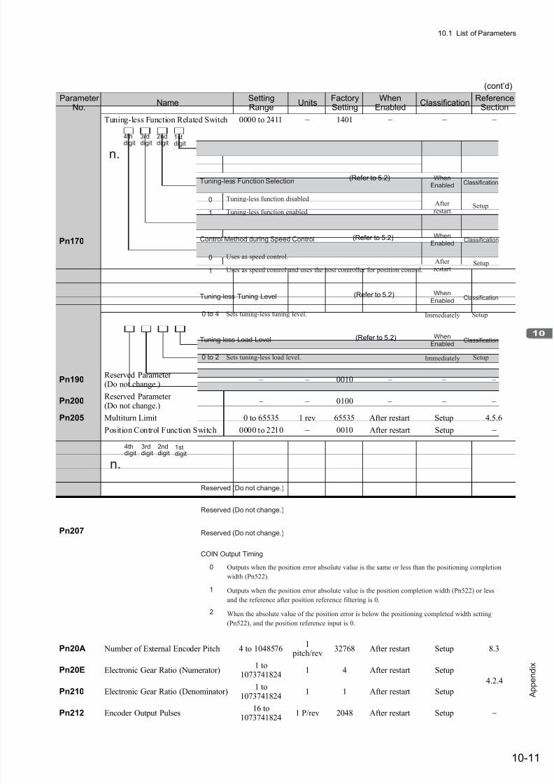
7/17/2019 Manual Yaskawa_servo_drive.pdf
http://slidepdf.com/reader/full/manual-yaskawaservodrivepdf 308/328
10.1 List of Parameters
10-11
A p p
e n d i x
Pn170
Tuning-less Function Related Switch 0000 to 2411 − 1401 − − −
Pn190Reserved Parameter (Do not change.)
– – 0010 – – –
Pn200Reserved Parameter (Do not change.)
– – 0100 – – –
Pn205 Multiturn Limit 0 to 65535 1 rev 65535 After restart Setup 4.5.6
Pn207
Position Control Function Switch 0000 to 2210 − 0010 After restart Setup −
Pn20A Number of External Encoder Pitch 4 to 10485761
pitch/rev32768 After restart Setup 8.3
Pn20E Electronic Gear Ratio (Numerator)1 to
10737418241 4 After restart Setup
4.2.4
Pn210 Electronic Gear Ratio (Denominator) 1 to1073741824
1 1 After restart Setup
Pn212 Encoder Output Pulses16 to
10737418241 P/rev 2048 After restart Setup −
(cont’d)
ParameterNo.
NameSettingRange
UnitsFactorySetting
WhenEnabled
ClassificationReference
Section
0
1
Tuning-less function disabled
Tuning-less function enabled
Tuning-less Function Selection
4thdigit
3rddigit
2nddigit
1stdigit
n.
After restart
WhenEnabled
0
1
Uses as speed control.
Uses as speed control and uses the host controller for position control.
Control Method during Speed Control
After restart
WhenEnabled
0 to 4 Sets tuning-less tuning level.
Tuning-less Tuning Level
Immediately
WhenEnabled
0 to 2 Sets tuning-less load level.
Tuning-less Load Level
Immediately
WhenEnabled
Setup
Classification
Setup
Classification
Setup
Classification
Setup
Classification
(Refer to 5.2)
(Refer to 5.2)
(Refer to 5.2)
(Refer to 5.2)
4thdigit
3rddigit
2nddigit
1stdigit
n.
Reserved (Do not change.)
0
1
2
Outputs when the position error absolute value is the same or less than the positioning completion
width (Pn522).
Outputs when the position error absolute value is the position completion width (Pn522) or less
and the reference after position reference filtering is 0.
When the absolute value of the position error is below the positioning completed width setting
(Pn522), and the position reference input is 0.
COIN Output Timing
Reserved (Do not change.)
Reserved (Do not change.)
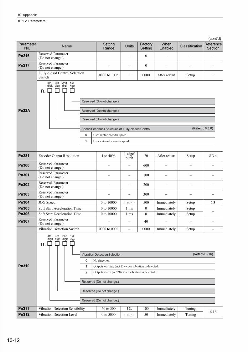
7/17/2019 Manual Yaskawa_servo_drive.pdf
http://slidepdf.com/reader/full/manual-yaskawaservodrivepdf 309/328
10 Appendix
10.1.2 Parameters
10-12
Pn216Reserved Parameter (Do not change.)
– – 0 – – –
Pn217Reserved Parameter (Do not change.)
– – 0 – – –
Pn22A
Fully-closed Control SelectionSwitch
0000 to 1003 − 0000 After restart Setup −
Pn281 Encoder Output Resolution 1 to 40961 edge/ pitch
20 After restart Setup 8.3.4
Pn300Reserved Parameter (Do not change.)
– – 600 – – –
Pn301Reserved Parameter (Do not change.)
– – 100 – – –
Pn302Reserved Parameter (Do not change.) – – 200 – – –
Pn303Reserved Parameter (Do not change.)
– – 300 – – –
Pn304 JOG Speed 0 to 10000 1 min-1 500 Immediately Setup 6.3
Pn305 Soft Start Acceleration Time 0 to 10000 1 ms 0 Immediately Setup−
Pn306 Soft Start Deceleration Time 0 to 10000 1 ms 0 Immediately Setup
Pn307Reserved Parameter (Do not change.)
– – 40 – – –
Pn310
Vibration Detection Switch 0000 to 0002 − 0000 Immediately Setup −
Pn311 Vibration Detection Sensibility 50 to 500 1% 100 Immediately Tuning6.16
Pn312 Vibration Detection Level 0 to 5000 1 min-1 50 Immediately Tuning
(cont’d)
ParameterNo.
NameSettingRange
UnitsFactorySetting
WhenEnabled
ClassificationReference
Section
4thdigit
3rddigit
2nddigit
1stdigit
n.
Reserved (Do not change.)
0
1
Uses motor encoder speed.
Uses external encoder speed.
Speed Feedback Selection at Fully-closed Control
Reserved (Do not change.)
Reserved (Do not change.)
(Refer to 8.3.8)
4thdigit
3rddigit
2nddigit
1stdigit
n.
0
1
2
No detection.
Outputs warning (A.911) when vibration is detected.
Outputs alarm (A.520) when vibration is detected.
Vibration Detection Selection
Reserved (Do not change.)
Reserved (Do not change.)
Reserved (Do not change.)
(Refer to 6.16)

7/17/2019 Manual Yaskawa_servo_drive.pdf
http://slidepdf.com/reader/full/manual-yaskawaservodrivepdf 310/328
10.1 List of Parameters
10-13
A p p
e n d i x
Pn324Moment of Inertia Calculating StartLevel
0 to 20000 1% 300 Immediately Setup 5.3.2
Pn400Reserved Parameter (Do not change.)
– – 30 – – –
Pn4011st Step 1st Torque Reference FilterTime Constant
0 to 65535 0.01 ms 100 Immediately Tuning 5.9.3
Pn402 Forward Torque Limit 0 to 800 1% 800 Immediately Setup−
Pn403 Reverse Torque Limit 0 to 800 1% 800 Immediately Setup
Pn404 Forward External Torque Limit 0 to 800 1% 100 Immediately Setup−
Pn405 Reverse External Torque Limit 0 to 800 1% 100 Immediately Setup
Pn406 Emergency Stop Torque 0 to 800 1% 800 Immediately Setup 4.2.3
Pn407 Speed Limit during Torque Control 0 to 10000 1 min-1 10000 Immediately Setup −
Pn408
Torque Related Function Switch 0000 to 1111 − 0000 − Setup −
Pn409 1st Notch Filter Frequency 50 to 5000 1 Hz 5000 Immediately Tuning
5.9.3
Pn40A 1st Notch Filter Q Value 50 to 1000 0.01 70 Immediately Tuning
Pn40B 1st Notch Filter Depth 0 to 1000 0.001 0 Immediately Tuning
Pn40C 2nd Notch Filter Frequency 50 to 5000 1 Hz 5000 Immediately Tuning
Pn40D 2nd Notch Filter Q Value 50 to 1000 0.01 70 Immediately Tuning
Pn40E 2nd Notch Filter Depth 0 to 1000 0.001 0 Immediately Tuning
Pn40F2nd Step 2nd Torque Reference FilterFrequency
100 to 5000 1 Hz 5000 Immediately Tuning
Pn4102nd Step 2nd Torque Reference FilterQ Value
50 to 100 0.01 50 Immediately Tuning
Pn412 1st Step 2nd Torque Reference FilterTime Constant
0 to 65535 0.01 ms 100 Immediately Tuning
(cont’d)
ParameterNo.
NameSettingRange
UnitsFactorySetting
WhenEnabled
ClassificationReference
Section
4thdigit
3rddigit
2nddigit
1stdigit
n.
0
1
N/A
Uses 1st step notch filter for torque reference.
1st Step Notch Filter Selection
N/A
Uses 2nd step notch filter for torque reference.
2nd Step Notch Filter Selection
0
1
0
1
Speed Limit Selection
Disables use friction compesation function.
Enables friction compsation function.
Friction Compensation Function Selection
0
1
WhenEnabled
WhenEnabled
WhenEnabled
WhenEnabled
Immediately
After restart
Immediately
Immediately
Uses the smaller value between motor max. speed and
parameter Pn407 as speed limit value.
Uses the smaller value between overspeed detection speed
and parameter Pn407 as speed limit value.
Setup
Classification
Setup
Classification
Setup
Classification
Setup
Classification(Refer to 5.9.3)
(Refer to 5.9.3)
(Refer to 5.8.2)

7/17/2019 Manual Yaskawa_servo_drive.pdf
http://slidepdf.com/reader/full/manual-yaskawaservodrivepdf 311/328
10 Appendix
10.1.2 Parameters
10-14
Pn423Reserved Parameter (Do not change.)
– – 0000 – – –
Pn424Torque Limit at Main Circuit VoltageDrop
0 to 100 1% 50 Immediately Setup
4.2.10
Pn425Release Time for Torque Limit atMain Circuit Voltage Drop
0 to 1000 1 ms 100 Immediately Setup
Pn456 Sweep Torque Reference Amplitude 1 to 800 1% 15 Immediately Tuning 6.19
Pn460
Notch Filter Adjustment Switch 0000 to 0101 − 0101 Immediately Tuning5.2.15.3.15.5.1
Pn501Reserved Parameter (Do not change.) – – 10 – – –
Pn502 Rotation Detection Level 1 to 10000 1 min-1 20 Immediately Setup −
Pn503Speed Coincidence Signal OutputWidth
0 to 100 1 min-1 10 Immediately Setup −
Pn506Brake Reference - Servo OFF DelayTime
0 to 50 10 ms 0 Immediately Setup
4.2.7Pn507 Brake Reference Output Speed Level 0 to 10000 1 min-1 100 Immediately Setup
Pn508Waiting Time for Brake Signal WhenMotor Running
10 to 100 10 ms 50 Immediately Setup
Pn509 Instantaneous Power Cut Hold time 20 to 1000 1 ms 20 Immediately Setup 4.2.9
(cont’d)
ParameterNo.
NameSettingRange
UnitsFactorySetting
WhenEnabled
ClassificationReference
Section
0
1
1st step notch filter is not adjusted automatically with utility function.
1st step notch filter is adjusted automatically with utility function.
Notch Filter Adjustment Selection 1
4thdigit
3rddigit
2nddigit
1stdigit
n.
Reserved (Do not change.)
0
1
2nd step notch filter is not adjusted automatically with utility function.
2nd step notch filter is adjusted automatically with utility function.
Notch Filter Adjustment Selection 2
Reserved (Do not change.)

7/17/2019 Manual Yaskawa_servo_drive.pdf
http://slidepdf.com/reader/full/manual-yaskawaservodrivepdf 312/328
10.1 List of Parameters
10-15
A p p
e n d i x
Pn50A
Input Signal Selection 1 0000 to FFF1 − 1881 After restart Setup −
(cont’d)
ParameterNo.
NameSettingRange
UnitsFactorySetting
WhenEnabled
ClassificationReference
Section
4thdigit 3rddigit 2nddigit 1stdigit
n.
0
1
2
3
4
5
6
7
8
9
A
B
C
D
E
F
Forward run allowed when CN1-13 input signal is ON (L-level)
Forward run allowed when CN1-7 input signal is ON (L-level)
Forward run allowed when CN1-8 input signal is ON (L-level)
Forward run allowed when CN1-9 input signal is ON (L-level)
Forward run allowed when CN1-10 input signal is ON (L-level)
Forward run allowed when CN1-11 input signal is ON (L-level)
Forward run allowed when CN1-12 input signal is ON (L-level)
Forward run prohibited
Forward run allowed
Forward run allowed when CN1-13 input signal is OFF (H-level)
Forward run allowed when CN1-7 input signal is OFF (H-level)
Forward run allowed when CN1-8 input signal is OFF (H-level)
Forward run allowed when CN1-9 input signal is OFF (H-level)
Forward run allowed when CN1-10 input signal is OFF (H-level)
Forward run allowed when CN1-11 input signal is OFF (H-level)
Forward run allowed when CN1-12 input signal is OFF (H-level)
P-OT Signal Mapping
Reserved (Do not change.)
Reserved (Do not change.)
Reserved (Do not change.)
(Refer to 4.2.3)

7/17/2019 Manual Yaskawa_servo_drive.pdf
http://slidepdf.com/reader/full/manual-yaskawaservodrivepdf 313/328
10 Appendix
10.1.2 Parameters
10-16
Pn50B
Input Signal Selection 2 0000 to FFFF − 8882 After restart Setup −
(cont’d)
ParameterNo.
NameSettingRange
UnitsFactorySetting
WhenEnabled
ClassificationReference
Section
4thdigit
3rddigit
2nddigit
1stdigit
n.
/P-CL Signal Mapping
N-OT Signal Mapping
0
1
2
3
4
5
67
8
9
A
B
C
D
E
F
Reverse run allowed when CN1-13 input signal is ON (L-level).
Reverse run allowed when CN1-7 input signal is ON (L-level).
Reverse run allowed when CN1-8 input signal is ON (L-level).
Reverse run allowed when CN1-9 input signal is ON (L-level) .
Reverse run allowed when CN1-10 input signal is ON (L-level).
Reverse run allowed when CN1-11 input signal is ON (L-level).
Reverse run allowed when CN1-12 input signal is ON (L-level).Reverse run prohibited.
Reverse run allowed.
Reverse run allowed when CN1-13 input signal is OFF (H-level).
Reverse run allowed when CN1-7 input signal is OFF (H-level).
Reverse run allowed when CN1-8 input signal is OFF (H-level).
Reverse run allowed when CN1-9 input signal is OFF (H-level).
Reverse run allowed when CN1-10 input signal is OFF (H-level).
Reverse run allowed when CN1-11 input signal is OFF (H-level).
Reverse run allowed when CN1-12 input signal is OFF (H-level).
0 to F
/N-CL Signal Mapping
Reserved (Do not change.)
0
1
2
3
4
5
6
78
9
A
B
C
D
E
F
ON when CN1-13 input signal is ON (L-level)
ON when CN1-7 input signal is ON (L-level)
ON when CN1-8 input signal is ON (L-level)
ON when CN1-9 input signal is ON (L-level)
ON when CN1-10 input signal is ON (L-level)
ON when CN1-11 input signal is ON (L-level)
ON when CN1-12 input signal is ON (L-level)
Sets signal ON.Sets signal OFF.
OFF when CN1-13 input signal is OFF (H-level)
OFF when CN1-7 input signal is OFF (H-level)
OFF when CN1-8 input signal is OFF (H-level)
OFF when CN1-9 input signal is OFF (H-level)
OFF when CN1-10 input signal is OFF (H-level)
OFF when CN1-11 input signal is OFF (H-level)
OFF when CN1-12 input signal is OFF (H-level)
Same as /P-CL signal mapping
(Refer to 4.2.3)
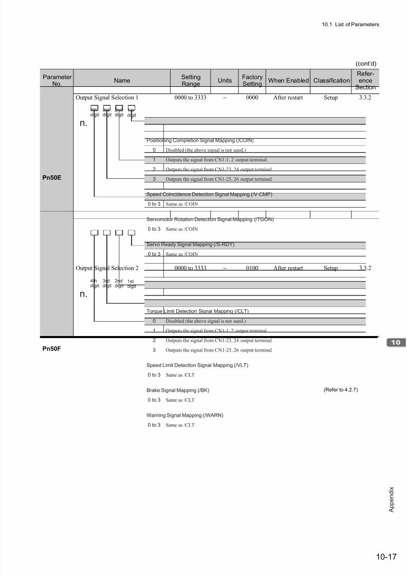
7/17/2019 Manual Yaskawa_servo_drive.pdf
http://slidepdf.com/reader/full/manual-yaskawaservodrivepdf 314/328
10.1 List of Parameters
10-17
A p p
e n d i x
(cont’d)
ParameterNo.
NameSettingRange
UnitsFactorySetting
When Enabled ClassificationRefer-ence
Section
Pn50E
Output Signal Selection 1 0000 to 3333 − 0000 After restart Setup 3.3.2
Pn50F
Output Signal Selection 2 0000 to 3333 − 0100 After restart Setup 3.3.2
4thdigit
3rddigit
2nddigit
1stdigit
n.
0 to 3 Same as /COIN
Servomotor Rotation Detection Signal Mapping (/TGON)
Positioning Completion Signal Mapping (/COIN)
0
1
2
3
0 to 3 Same as /COIN
Speed Coincidence Detection Signal Mapping (/V-CMP)
0 to 3 Same as /COIN
Servo Ready Signal Mapping (/S-RDY)
Disabled (the above signal is not used.)
Outputs the signal from CN1-1, 2 output terminal.
Outputs the signal from CN1-23, 24 output terminal.
Outputs the signal from CN1-25, 26 output terminal.
4thdigit
3rddigit
2nddigit
1stdigit
n.
0 to 3 Same as /CLT
Brake Signal Mapping (/BK)
Torque Limit Detection Signal Mapping (/CLT)
0
1
2
3
0 to 3 Same as /CLT
Speed Limit Detection Signal Mapping (/VLT)
0 to 3 Same as /CLT
Warning Signal Mapping (/WARN)
Disabled (the above signal is not used.)
Outputs the signal from CN1-1, 2 output terminal.
Outputs the signal from CN1-23, 24 output terminal.
Outputs the signal from CN1-25, 26 output terminal.
(Refer to 4.2.7)
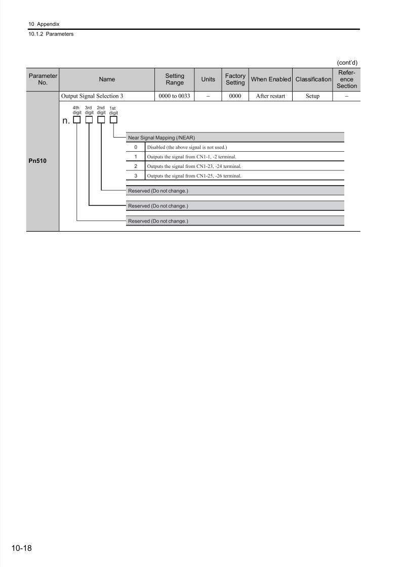
7/17/2019 Manual Yaskawa_servo_drive.pdf
http://slidepdf.com/reader/full/manual-yaskawaservodrivepdf 315/328
10 Appendix
10.1.2 Parameters
10-18
Pn510
Output Signal Selection 3 0000 to 0033 − 0000 After restart Setup −
(cont’d)
ParameterNo.
NameSettingRange
UnitsFactorySetting
When Enabled ClassificationRefer-ence
Section
4thdigit
3rddigit
2nddigit
1stdigit
n.
Near Signal Mapping (/NEAR)
0
1
2
3
Reserved (Do not change.)
Disabled (the above signal is not used.)
Outputs the signal from CN1-1, -2 terminal.
Outputs the signal from CN1-23, -24 terminal.
Outputs the signal from CN1-25, -26 terminal.
Reserved (Do not change.)
Reserved (Do not change.)

7/17/2019 Manual Yaskawa_servo_drive.pdf
http://slidepdf.com/reader/full/manual-yaskawaservodrivepdf 316/328
10.1 List of Parameters
10-19
A p p
e n d i x
Pn511
Input Signal Selection 5 0000 to FFFF − 6543 After restart Setup −
(cont’d)
ParameterNo.
NameSettingRange
UnitsFactorySetting
When Enabled ClassificationRefer-ence
Section
4thdigit
3rddigit
2nddigit
1stdigit
n.
Same as /SI4 signal mapping.
Input Signal 5 Mapping for Command Option Module (/SI5)
Input Signal 3 Mapping for Command Option Module (/SI3)
0
1
2
3
4
5
6
7
8
9
A
B
C
D
E
F
Inputs the signal from CN1-13 input terminal.
Inputs the signal from CN1-7 input terminal.
Inputs the signal from CN1-8 input terminal.
Inputs the signal from CN1-9 input terminal.
Inputs the signal from CN1-10 input terminal.
Inputs the signal from CN1-11 input terminal.
Inputs the signal from CN1-12 input terminal.
Sets signal ON.
Sets signal OFF.
Inputs the reverse signal from CN1-13 input terminal.
Inputs the reverse signal from CN1-7 input terminal.
Inputs the reverse signal from CN1-8 input terminal.
Inputs the reverse signal from CN1-9 input terminal.
Inputs the reverse signal from CN1-10 input terminal.
Inputs the reverse signal from CN1-11 input terminal.
Inputs the reverse signal from CN1-12 input terminal.
Input Signal 4 Mapping for Command Option Module (/SI4)
4
5
6
7
8
D
E
F
Inputs the signal from CN1-10 input terminal.
Inputs the signal from CN1-11 input terminal.
Inputs the signal from CN1-12 input terminal.
Sets signal ON.
Sets signal OFF.
Inputs the reverse signal from CN1-10 input terminal.
Inputs the reverse signal from CN1-11 input terminal.
Inputs the reverse signal from CN1-12 input terminal.
Sets signal OFF.
Same as /SI4 signal mapping.
Input Signal 6 Mapping for Command Option Module (/SI6)
0 to 3
9 to F
0 to F
0 to F
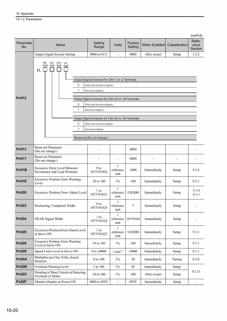
7/17/2019 Manual Yaskawa_servo_drive.pdf
http://slidepdf.com/reader/full/manual-yaskawaservodrivepdf 317/328
10 Appendix
10.1.2 Parameters
10-20
Pn512
Output Signal Inverse Setting 0000 to 0111 − 0000 After restart Setup 3.3.2
Pn513Reserved Parameter (Do not change.)
– – 0000 – – –
Pn517Reserved Parameter (Do not change.)
– – 0000 – – –
Pn51B Excessive Error Level BetweenServomotor and Load Positions
0 to1073741824
1
referenceunit
1000 Immediately Setup 8.3.6
Pn51EExcessive Position Error WarningLevel
10 to 100 1% 100 Immediately Setup 9.2.1
Pn520 Excessive Position Error Alarm Level1 to
1073741823
1reference
unit5242880 Immediately Setup
5.1.4
9.1.1
Pn522 Positioning Completed Width0 to
1073741824
1reference
unit7 Immediately Setup –
Pn524 NEAR Signal Width1 to
1073741824
1reference
unit1073741824 Immediately Setup –
Pn526Excessive Position Error Alarm Levelat Servo ON
1 to1073741823
1reference
unit5242880 Immediately Setup 9.1.1
Pn528Excessive Position Error WarningLevel at Servo ON
10 to 100 1% 100 Immediately Setup 9.2.1
Pn529 Speed Limit Level at Servo ON 0 to 10000 1 min-1 10000 Immediately Setup 9.1.1
Pn52AMultiplier per One Fully-closedRotation
0 to 100 1% 20 Immediately Tuning 8.3.6
Pn52B Overload Warning Level 1 to 100 1% 20 Immediately Setup
4.2.11Pn52C
Derating of Base Current at DetectingOverload of Motor
10 to 100 1% 100 After restart Setup
Pn52F Monitor Display at Power ON 0000 to 0FFF − 0FFF Immediately Setup –
(cont’d)
ParameterNo.
NameSettingRange
UnitsFactorySetting
When Enabled ClassificationRefer-ence
Section
4thdigit
3rddigit
2nddigit
1stdigit
n.
Output Signal Inversion for CN1-1 or -2 Terminals
0
1
Does not inverse outputs.
Inverses outputs.
Output Signal Inversion for CN1-23 or -24 Terminals
0
1
Does not inverse outputs.
Inverses outputs.
Output Signal Inversion for CN1-25 or -26 Terminals
0
1
Does not inverse outputs.
Inverses outputs.
Reserved (Do not change.)
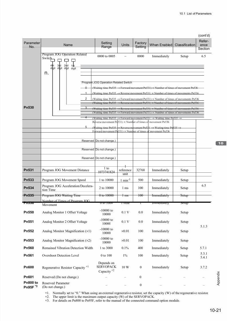
7/17/2019 Manual Yaskawa_servo_drive.pdf
http://slidepdf.com/reader/full/manual-yaskawaservodrivepdf 318/328
10.1 List of Parameters
10-21
A p p
e n d i x
Pn530
Program JOG Operation RelatedSwitch 0000 to 0005 − 0000 Immediately Setup 6.5
Pn531 Program JOG Movement Distance 1 to1073741824
1reference
unit32768 Immediately Setup
6.5
Pn533 Program JOG Movement Speed 1 to 10000 1 min-1 500 Immediately Setup
Pn534Program JOG Acceleration/Decelera-tion Time
2 to 10000 1 ms 100 Immediately Setup
Pn535 Program JOG Waiting Time 0 to 10000 1 ms 100 Immediately Setup
Pn536 Number of Times of Program JOGMovement
0 to 1000 1 time 1 Immediately Setup
Pn550 Analog Monitor 1 Offset Voltage-10000 to
100000.1 V 0.0 Immediately Setup
5.1.3
Pn551 Analog Monitor 2 Offset Voltage-10000 to
10000
0.1 V 0.0 Immediately Setup
Pn552 Analog Monitor Magnification (×1)-10000 to
10000×0.01 100 Immediately Setup
Pn553 Analog Monitor Magnification (×2)-10000 to
10000×0.01 100 Immediately Setup
Pn560 Remained Vibration Detection Width 1 to 3000 0.1% 400 Immediately Setup 5.7.1
Pn561 Overshoot Detection Level 0 to 100 1% 100 Immediately Setup5.3.15.4.1
Pn600 Regenerative Resistor Capacity ∗1
Depends onSERVOPACK
Capacity ∗210 W 0 Immediately Setup 3.7.2
Pn601 Reserved (Do not change.) – – 0 – – –
Pn800 to
Pn95F *3
Reserved Parameter (Do not change.)
– – 0 – – –
∗1. Normally set to “0.” When using an external regenerative resistor, set the capacity (W) of the regenerative resistor.∗2. The upper limit is the maximum output capacity (W) of the SERVOPACK.∗3. For details on Pn800 to Pn95F, refer to the manual of the connected command option module.
(cont’d)
ParameterNo.
NameSettingRange
UnitsFactorySetting
When Enabled ClassificationRefer-ence
Section
4thdigit
3rddigit
2nddigit
1stdigit
n.
Program JOG Operation Related Switch
0
1
2
3
4
5
Reserved (Do not change.)
(Waiting time Pn535→ Forward movement Pn531) × Number of times of movement Pn536
(Waiting time Pn535 → Reverse movement Pn531) × Number of times of movements Pn536
(Waiting time Pn535 → Forward movement Pn531) × Number of times of movements Pn536
(Waiting time Pn535 → Reverse movement Pn531) × Number of times of movements Pn536
(Waiting time Pn535 → Reverse movement Pn531) × Number of times of movements Pn536
(Waiting time Pn535 → Forward movement Pn531) × Number of times of movements Pn536
(Waiting time Pn535 → Forward movement Pn531 → Waiting time Pn535 →
Reverse movement Pn531) × Number of times of movement Pn536
(Waiting time Pn535 → Reverse movement Pn531 → Waiting time Pn535→
Forward movement Pn531) × Number of times of movement Pn536
Reserved (Do not change.)
Reserved (Do not change.)
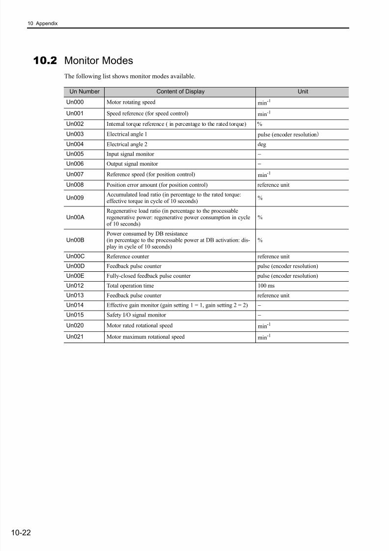
7/17/2019 Manual Yaskawa_servo_drive.pdf
http://slidepdf.com/reader/full/manual-yaskawaservodrivepdf 319/328
10 Appendix
10-22
10.2 Monitor Modes
The following list shows monitor modes available.
Un Number Content of Display Unit
Un000 Motor rotating speed min-1
Un001 Speed reference (for speed control) min-1
Un002 Internal torque reference ( in percentage to the rated torque) %
Un003 Electrical angle 1 pulse (encoder resolution)
Un004 Electrical angle 2 deg
Un005 Input signal monitor −
Un006 Output signal monitor −
Un007 Reference speed (for position control) min-1
Un008 Position error amount (for position control) reference unit
Un009 Accumulated load ratio (in percentage to the rated torque:effective torque in cycle of 10 seconds)
%
Un00ARegenerative load ratio (in percentage to the processableregenerative power: regenerative power consumption in cycleof 10 seconds)
%
Un00BPower consumed by DB resistance(in percentage to the processable power at DB activation: dis- play in cycle of 10 seconds)
%
Un00C Reference counter reference unit
Un00D Feedback pulse counter pulse (encoder resolution)
Un00E Fully-closed feedback pulse counter pulse (encoder resolution)
Un012 Total operation time 100 ms
Un013 Feedback pulse counter reference unit
Un014 Effective gain monitor (gain setting 1 = 1, gain setting 2 = 2) −
Un015 Safety I/O signal monitor −
Un020 Motor rated rotational speed min-1
Un021 Motor maximum rotational speed min-1
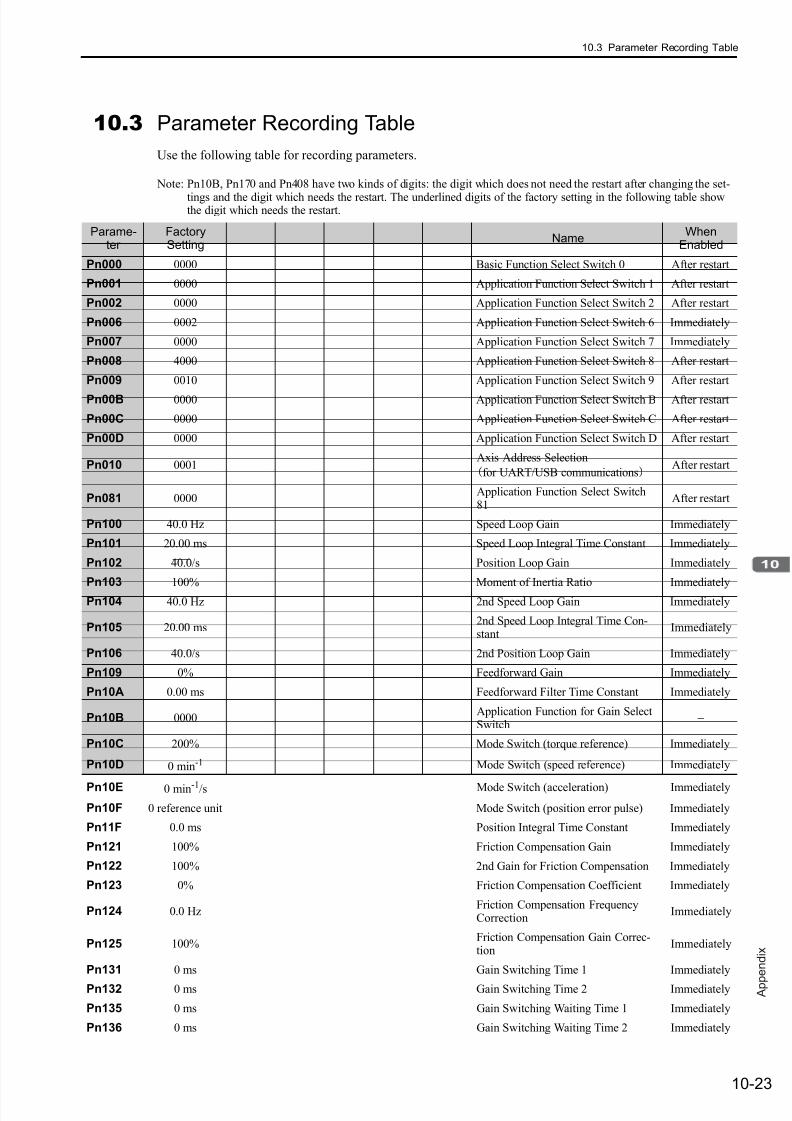
7/17/2019 Manual Yaskawa_servo_drive.pdf
http://slidepdf.com/reader/full/manual-yaskawaservodrivepdf 320/328
10.3 Parameter Recording Table
10-23
A p p
e n d i x
10.3 Parameter Recording Table
Use the following table for recording parameters.
Note: Pn10B, Pn170 and Pn408 have two kinds of digits: the digit which does not need the restart after changing the set-
tings and the digit which needs the restart. The underlined digits of the factory setting in the following table showthe digit which needs the restart.
Parame-ter
FactorySetting
NameWhen
Enabled
Pn000 0000 Basic Function Select Switch 0 After restart
Pn001 0000 Application Function Select Switch 1 After restart
Pn002 0000 Application Function Select Switch 2 After restart
Pn006 0002 Application Function Select Switch 6 Immediately
Pn007 0000 Application Function Select Switch 7 Immediately
Pn008 4000 Application Function Select Switch 8 After restart
Pn009 0010 Application Function Select Switch 9 After restart
Pn00B 0000 Application Function Select Switch B After restart
Pn00C 0000 Application Function Select Switch C After restart
Pn00D 0000 Application Function Select Switch D After restart
Pn010 0001Axis Address Selection
(for UART/USB communications)After restart
Pn081 0000Application Function Select Switch81
After restart
Pn100 40.0 Hz Speed Loop Gain Immediately
Pn101 20.00 ms Speed Loop Integral Time Constant Immediately
Pn102 40.0/s Position Loop Gain Immediately
Pn103 100% Moment of Inertia Ratio Immediately
Pn104 40.0 Hz 2nd Speed Loop Gain Immediately
Pn105 20.00 ms2nd Speed Loop Integral Time Con-stant
Immediately
Pn106 40.0/s 2nd Position Loop Gain Immediately
Pn109 0% Feedforward Gain Immediately
Pn10A 0.00 ms Feedforward Filter Time Constant Immediately
Pn10B 0000Application Function for Gain SelectSwitch
−
Pn10C 200% Mode Switch (torque reference) Immediately
Pn10D 0 min-1 Mode Switch (speed reference) Immediately
Pn10E 0 min-1/s Mode Switch (acceleration) Immediately
Pn10F 0 reference unit Mode Switch (position error pulse) Immediately
Pn11F 0.0 ms Position Integral Time Constant Immediately
Pn121 100% Friction Compensation Gain Immediately
Pn122 100% 2nd Gain for Friction Compensation Immediately
Pn123 0% Friction Compensation Coefficient Immediately
Pn124 0.0 HzFriction Compensation FrequencyCorrection
Immediately
Pn125 100%Friction Compensation Gain Correc-tion
Immediately
Pn131 0 ms Gain Switching Time 1 Immediately
Pn132 0 ms Gain Switching Time 2 Immediately
Pn135 0 ms Gain Switching Waiting Time 1 Immediately
Pn136 0 ms Gain Switching Waiting Time 2 Immediately
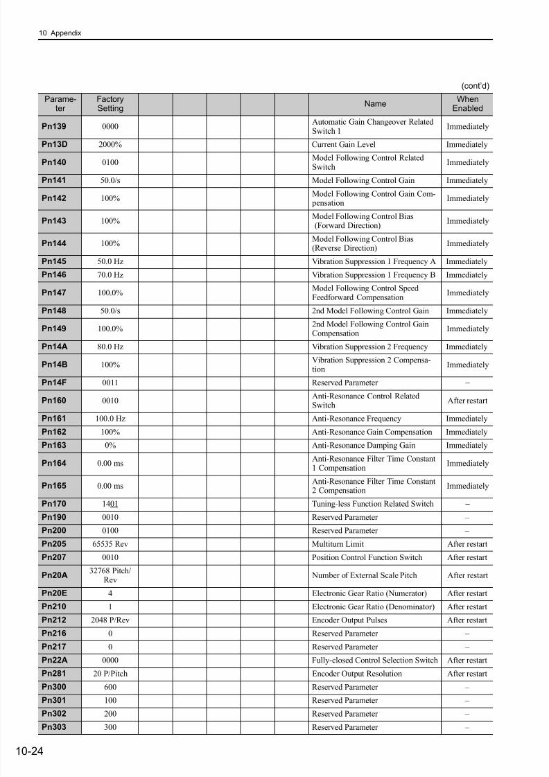
7/17/2019 Manual Yaskawa_servo_drive.pdf
http://slidepdf.com/reader/full/manual-yaskawaservodrivepdf 321/328
10 Appendix
10-24
Pn139 0000Automatic Gain Changeover RelatedSwitch 1
Immediately
Pn13D 2000% Current Gain Level Immediately
Pn140 0100Model Following Control RelatedSwitch
Immediately
Pn141 50.0/s Model Following Control Gain Immediately
Pn142 100%Model Following Control Gain Com- pensation
Immediately
Pn143 100%Model Following Control Bias (Forward Direction)
Immediately
Pn144 100%Model Following Control Bias(Reverse Direction)
Immediately
Pn145 50.0 Hz Vibration Suppression 1 Frequency A Immediately
Pn146 70.0 Hz Vibration Suppression 1 Frequency B Immediately
Pn147 100.0%Model Following Control SpeedFeedforward Compensation
Immediately
Pn148 50.0/s 2nd Model Following Control Gain Immediately
Pn149 100.0%2nd Model Following Control GainCompensation
Immediately
Pn14A 80.0 Hz Vibration Suppression 2 Frequency Immediately
Pn14B 100%Vibration Suppression 2 Compensa-tion
Immediately
Pn14F 0011 Reserved Parameter −
Pn160 0010Anti-Resonance Control Related
Switch
After restart
Pn161 100.0 Hz Anti-Resonance Frequency Immediately
Pn162 100% Anti-Resonance Gain Compensation Immediately
Pn163 0% Anti-Resonance Damping Gain Immediately
Pn164 0.00 msAnti-Resonance Filter Time Constant1 Compensation
Immediately
Pn165 0.00 msAnti-Resonance Filter Time Constant2 Compensation
Immediately
Pn170 1401 Tuning-less Function Related Switch −
Pn190 0010 Reserved Parameter –
Pn200 0100 Reserved Parameter –
Pn205 65535 Rev Multiturn Limit After restart
Pn207 0010 Position Control Function Switch After restart
Pn20A32768 Pitch/
Rev Number of External Scale Pitch After restart
Pn20E 4 Electronic Gear Ratio (Numerator) After restart
Pn210 1 Electronic Gear Ratio (Denominator) After restart
Pn212 2048 P/Rev Encoder Output Pulses After restart
Pn216 0 Reserved Parameter –
Pn217 0 Reserved Parameter –
Pn22A 0000 Fully-closed Control Selection Switch After restart
Pn281 20 P/Pitch Encoder Output Resolution After restart
Pn300 600 Reserved Parameter –
Pn301 100 Reserved Parameter –
Pn302 200 Reserved Parameter –
Pn303 300 Reserved Parameter –
(cont’d)
Parame-ter
FactorySetting
NameWhen
Enabled
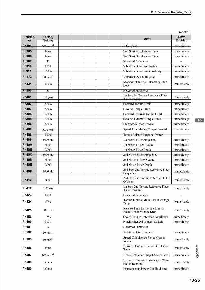
7/17/2019 Manual Yaskawa_servo_drive.pdf
http://slidepdf.com/reader/full/manual-yaskawaservodrivepdf 322/328
10.3 Parameter Recording Table
10-25
A p p
e n d i x
Pn304 500 min-1 JOG Speed Immediately
Pn305 0 ms Soft Start Acceleration Time Immediately
Pn306 0 ms Soft Start Deceleration Time Immediately
Pn307 40 Reserved Parameter –
Pn310 0000 Vibration Detection Switch Immediately
Pn311 100% Vibration Detection Sensibility Immediately
Pn312 50 min-1 Vibration Detection Level Immediately
Pn324 300%Moment of Inertia Calculating StartLevel
Immediately
Pn400 30 Reserved Parameter –
Pn401 1.00 ms1st Step 1st Torque Reference FilterTime Constant
Immediately
Pn402 800% Forward Torque Limit Immediately
Pn403 800% Reverse Torque Limit Immediately
Pn404 100% Forward External Torque Limit Immediately
Pn405 100% Reverse External Torque Limit Immediately
Pn406 800% Emergency Stop Torque Immediately
Pn407 10000 min-1 Speed Limit during Torque Control Immediately
Pn408 0000 Torque Related Function Switch −
Pn409 5000 Hz 1st Notch Filter Frequency Immediately
Pn40A 0.70 1st Notch Filter Q Value Immediately
Pn40B 0.000 1st Notch Filter Depth Immediately
Pn40C 5000 Hz 2nd Notch Filter Frequency Immediately
Pn40D 0.70 2nd Notch Filter Q Value Immediately
Pn40E 0.000 2nd Notch Filter Depth Immediately
Pn40F 5000 Hz2nd Step 2nd Torque Reference FilterFrequency
Immediately
Pn410 0.502nd Step 2nd Torque Reference FilterQ Value
Immediately
Pn412 1.00 ms1st Step 2nd Torque Reference FilterTime Constant
Immediately
Pn423 0000 Reserved Parameter –
Pn424 50%
Torque Limit at Main Circuit Voltage
Drop Immediately
Pn425 100 msRelease Time for Torque Limit atMain Circuit Voltage Drop
Immediately
Pn456 15% Sweep Torque Reference Amplitude Immediately
Pn460 0101 Notch Filter Adjustment Switch Immediately
Pn501 10 Reserved Parameter –
Pn502 20 min-1 Rotation Detection Level Immediately
Pn503 10 min-1 Speed Coincidence Signal OutputWidth
Immediately
Pn506 0 msBrake Reference - Servo OFF DelayTime
Immediately
Pn507 100 min-1 Brake Reference Output Speed Level Immediately
Pn508 50 msWaiting Time for Brake Signal WhenMotor Running
Immediately
Pn509 20 ms Instantaneous Power Cut Hold time Immediately
(cont’d)
Parame-ter
FactorySetting
NameWhen
Enabled
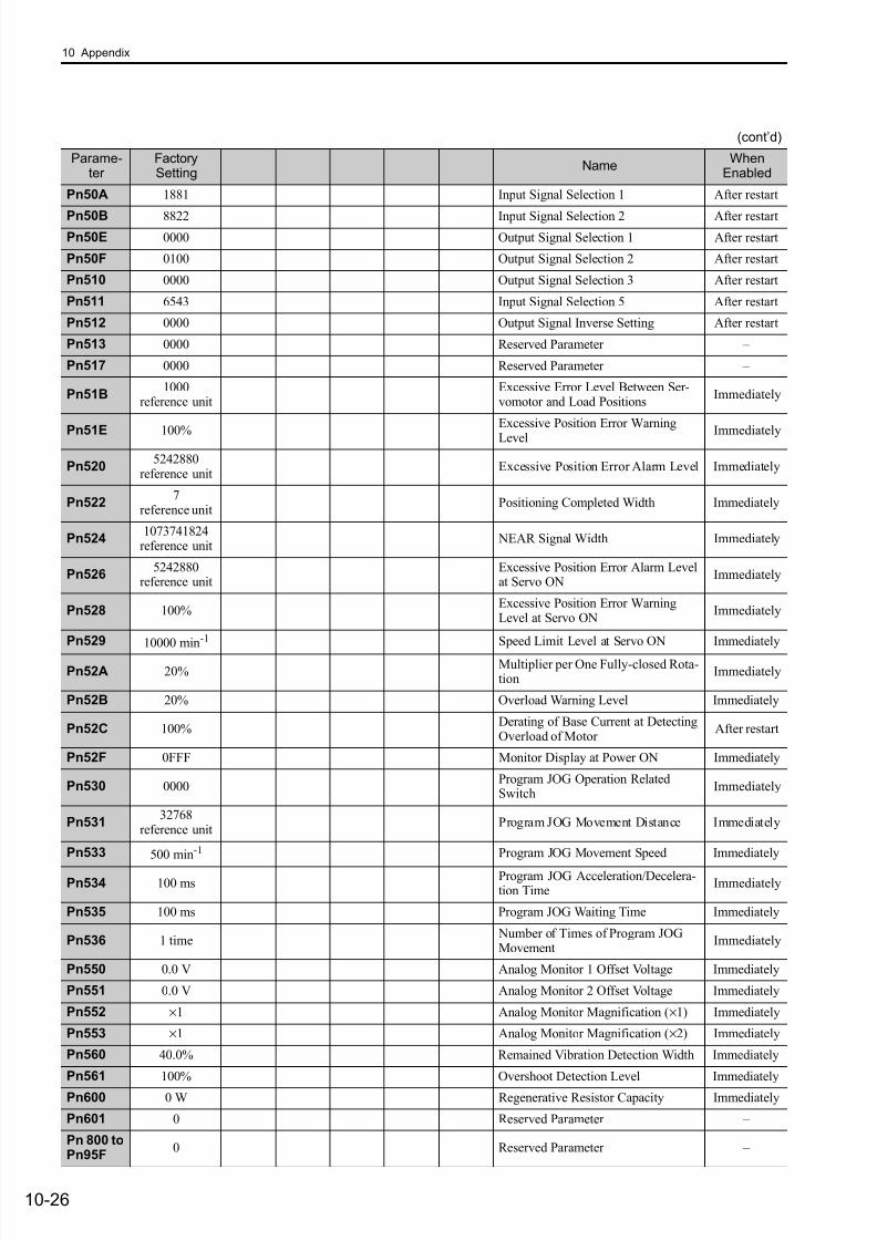
7/17/2019 Manual Yaskawa_servo_drive.pdf
http://slidepdf.com/reader/full/manual-yaskawaservodrivepdf 323/328
10 Appendix
10-26
Pn50A 1881 Input Signal Selection 1 After restart
Pn50B 8822 Input Signal Selection 2 After restartPn50E 0000 Output Signal Selection 1 After restart
Pn50F 0100 Output Signal Selection 2 After restart
Pn510 0000 Output Signal Selection 3 After restart
Pn511 6543 Input Signal Selection 5 After restart
Pn512 0000 Output Signal Inverse Setting After restart
Pn513 0000 Reserved Parameter –
Pn517 0000 Reserved Parameter –
Pn51B1000
reference unitExcessive Error Level Between Ser-vomotor and Load Positions
Immediately
Pn51E 100%
Excessive Position Error Warning
Level Immediately
Pn5205242880
reference unitExcessive Position Error Alarm Level Immediately
Pn5227
reference unitPositioning Completed Width Immediately
Pn5241073741824
reference unit NEAR Signal Width Immediately
Pn5265242880
reference unitExcessive Position Error Alarm Levelat Servo ON
Immediately
Pn528 100%Excessive Position Error WarningLevel at Servo ON
Immediately
Pn529 10000 min-1 Speed Limit Level at Servo ON Immediately
Pn52A 20%Multiplier per One Fully-closed Rota-tion
Immediately
Pn52B 20% Overload Warning Level Immediately
Pn52C 100%Derating of Base Current at DetectingOverload of Motor
After restart
Pn52F 0FFF Monitor Display at Power ON Immediately
Pn530 0000Program JOG Operation RelatedSwitch
Immediately
Pn53132768
reference unitProgram JOG Movement Distance Immediately
Pn533 500 min-1 Program JOG Movement Speed Immediately
Pn534 100 msProgram JOG Acceleration/Decelera-tion Time
Immediately
Pn535 100 ms Program JOG Waiting Time Immediately
Pn536 1 time Number of Times of Program JOGMovement
Immediately
Pn550 0.0 V Analog Monitor 1 Offset Voltage Immediately
Pn551 0.0 V Analog Monitor 2 Offset Voltage Immediately
Pn552 ×1 Analog Monitor Magnification (×1) Immediately
Pn553 ×1 Analog Monitor Magnification (×2) Immediately
Pn560 40.0% Remained Vibration Detection Width Immediately
Pn561 100% Overshoot Detection Level Immediately
Pn600 0 W Regenerative Resistor Capacity Immediately
Pn601 0 Reserved Parameter –
Pn 800 toPn95F
0 Reserved Parameter –
(cont’d)
Parame-ter
FactorySetting
NameWhen
Enabled
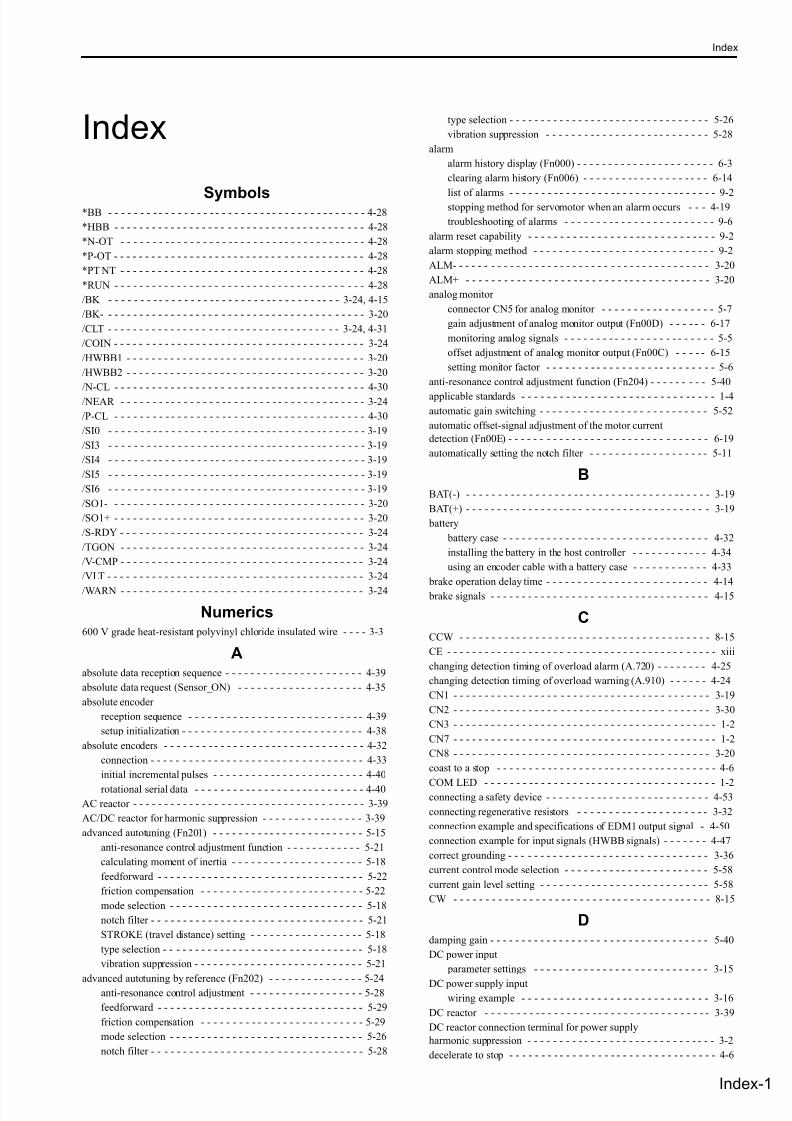
7/17/2019 Manual Yaskawa_servo_drive.pdf
http://slidepdf.com/reader/full/manual-yaskawaservodrivepdf 324/328
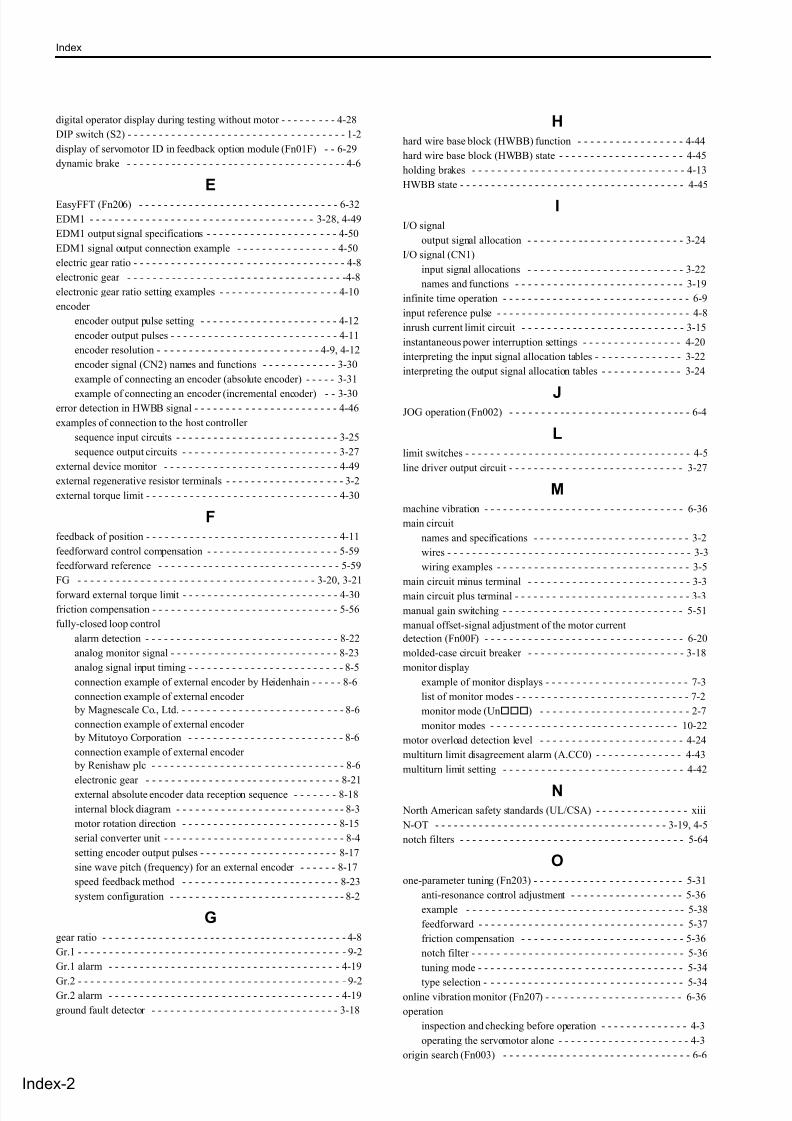
7/17/2019 Manual Yaskawa_servo_drive.pdf
http://slidepdf.com/reader/full/manual-yaskawaservodrivepdf 325/328
Index
ndex-2
digital operator display during testing without motor - - - - - - - - - 4-28
DIP switch (S2) - - - - - - - - - - - - - - - - - - - - - - - - - - - - - - - - - - - 1-2
display of servomotor ID in feedback option module (Fn01F) - - 6-29
dynamic brake - - - - - - - - - - - - - - - - - - - - - - - - - - - - - - - - - - - 4-6
EEasyFFT (Fn206) - - - - - - - - - - - - - - - - - - - - - - - - - - - - - - - - 6-32
EDM1 - - - - - - - - - - - - - - - - - - - - - - - - - - - - - - - - - - - - 3-28, 4-49
EDM1 output signal specifications - - - - - - - - - - - - - - - - - - - - - 4-50
EDM1 signal output connection example - - - - - - - - - - - - - - - - 4-50
electric gear ratio - - - - - - - - - - - - - - - - - - - - - - - - - - - - - - - - - - 4-8
electronic gear - - - - - - - - - - - - - - - - - - - - - - - - - - - - - - - - - - -4-8
electronic gear ratio setting examples - - - - - - - - - - - - - - - - - - - 4-10
encoder
encoder output pulse setting - - - - - - - - - - - - - - - - - - - - - - 4-12
encoder output pulses - - - - - - - - - - - - - - - - - - - - - - - - - - - 4-11
encoder resolution - - - - - - - - - - - - - - - - - - - - - - - - - - 4-9, 4-12
encoder signal (CN2) names and functions - - - - - - - - - - - - 3-30
example of connecting an encoder (absolute encoder) - - - - - 3-31
example of connecting an encoder (incremental encoder) - - 3-30error detection in HWBB signal - - - - - - - - - - - - - - - - - - - - - - - 4-46
examples of connection to the host controller
sequence input circuits - - - - - - - - - - - - - - - - - - - - - - - - - - 3-25
sequence output circuits - - - - - - - - - - - - - - - - - - - - - - - - - 3-27
external device monitor - - - - - - - - - - - - - - - - - - - - - - - - - - - - 4-49
external regenerative resistor terminals - - - - - - - - - - - - - - - - - - - 3-2
external torque limit - - - - - - - - - - - - - - - - - - - - - - - - - - - - - - - 4-30
Ffeedback of position - - - - - - - - - - - - - - - - - - - - - - - - - - - - - - - 4-11
feedforward control compensation - - - - - - - - - - - - - - - - - - - - - 5-59
feedforward reference - - - - - - - - - - - - - - - - - - - - - - - - - - - - - 5-59
FG - - - - - - - - - - - - - - - - - - - - - - - - - - - - - - - - - - - - - - 3-20, 3-21
forward external torque limit - - - - - - - - - - - - - - - - - - - - - - - - - 4-30
friction compensation - - - - - - - - - - - - - - - - - - - - - - - - - - - - - - 5-56
fully-closed loop control
alarm detection - - - - - - - - - - - - - - - - - - - - - - - - - - - - - - - 8-22
analog monitor signal - - - - - - - - - - - - - - - - - - - - - - - - - - - 8-23
analog signal input timing - - - - - - - - - - - - - - - - - - - - - - - - - 8-5
connection example of external encoder by Heidenhain - - - - - 8-6
connection example of external encoder
by Magnescale Co., Ltd. - - - - - - - - - - - - - - - - - - - - - - - - - - 8-6
connection example of external encoder
by Mitutoyo Corporation - - - - - - - - - - - - - - - - - - - - - - - - - 8-6
connection example of external encoder
by Renishaw plc - - - - - - - - - - - - - - - - - - - - - - - - - - - - - - - 8-6
electronic gear - - - - - - - - - - - - - - - - - - - - - - - - - - - - - - - 8-21
external absolute encoder data reception sequence - - - - - - - 8-18
internal block diagram - - - - - - - - - - - - - - - - - - - - - - - - - - - 8-3
motor rotation direction - - - - - - - - - - - - - - - - - - - - - - - - - 8-15
serial converter unit - - - - - - - - - - - - - - - - - - - - - - - - - - - - - 8-4
setting encoder output pulses - - - - - - - - - - - - - - - - - - - - - - 8-17
sine wave pitch (frequency) for an external encoder - - - - - - 8-17
speed feedback method - - - - - - - - - - - - - - - - - - - - - - - - - 8-23
system configuration - - - - - - - - - - - - - - - - - - - - - - - - - - - - 8-2
Ggear ratio - - - - - - - - - - - - - - - - - - - - - - - - - - - - - - - - - - - - - - - 4-8
Gr.1 - - - - - - - - - - - - - - - - - - - - - - - - - - - - - - - - - - - - - - - - - - - 9-2
Gr.1 alarm - - - - - - - - - - - - - - - - - - - - - - - - - - - - - - - - - - - - - 4-19
Gr.2 - - - - - - - - - - - - - - - - - - - - - - - - - - - - - - - - - - - - - - - - - - - 9-2Gr.2 alarm - - - - - - - - - - - - - - - - - - - - - - - - - - - - - - - - - - - - - 4-19
ground fault detector - - - - - - - - - - - - - - - - - - - - - - - - - - - - - - 3-18
Hhard wire base block (HWBB) function - - - - - - - - - - - - - - - - - 4-44
hard wire base block (HWBB) state - - - - - - - - - - - - - - - - - - - - 4-45
holding brakes - - - - - - - - - - - - - - - - - - - - - - - - - - - - - - - - - - 4-13
HWBB state - - - - - - - - - - - - - - - - - - - - - - - - - - - - - - - - - - - - 4-45
II/O signal
output signal allocation - - - - - - - - - - - - - - - - - - - - - - - - - 3-24
I/O signal (CN1)
input signal allocations - - - - - - - - - - - - - - - - - - - - - - - - - 3-22
names and functions - - - - - - - - - - - - - - - - - - - - - - - - - - - 3-19
infinite time operation - - - - - - - - - - - - - - - - - - - - - - - - - - - - - - 6-9
input reference pulse - - - - - - - - - - - - - - - - - - - - - - - - - - - - - - - 4-8
inrush current limit circuit - - - - - - - - - - - - - - - - - - - - - - - - - - 3-15
instantaneous power interruption settings - - - - - - - - - - - - - - - - 4-20
interpreting the input signal allocation tables - - - - - - - - - - - - - - 3-22
interpreting the output signal allocation tables - - - - - - - - - - - - - 3-24
JJOG operation (Fn002) - - - - - - - - - - - - - - - - - - - - - - - - - - - - - 6-4
Llimit switches - - - - - - - - - - - - - - - - - - - - - - - - - - - - - - - - - - - - 4-5
line driver output circuit - - - - - - - - - - - - - - - - - - - - - - - - - - - - 3-27
Mmachine vibration - - - - - - - - - - - - - - - - - - - - - - - - - - - - - - - - 6-36
main circuit
names and specifications - - - - - - - - - - - - - - - - - - - - - - - - - 3-2
wires - - - - - - - - - - - - - - - - - - - - - - - - - - - - - - - - - - - - - - - 3-3
wiring examples - - - - - - - - - - - - - - - - - - - - - - - - - - - - - - - 3-5
main circuit minus terminal - - - - - - - - - - - - - - - - - - - - - - - - - - 3-3
main circuit plus terminal - - - - - - - - - - - - - - - - - - - - - - - - - - - - 3-3
manual gain switching - - - - - - - - - - - - - - - - - - - - - - - - - - - - - 5-51
manual offset-signal adjustment of the motor current
detection (Fn00F) - - - - - - - - - - - - - - - - - - - - - - - - - - - - - - - - 6-20
molded-case circuit breaker - - - - - - - - - - - - - - - - - - - - - - - - - 3-18
monitor display
example of monitor displays - - - - - - - - - - - - - - - - - - - - - - - 7-3
list of monitor modes - - - - - - - - - - - - - - - - - - - - - - - - - - - - 7-2
monitor mode (Un) - - - - - - - - - - - - - - - - - - - - - - - - 2-7
monitor modes - - - - - - - - - - - - - - - - - - - - - - - - - - - - - - 10-22
motor overload detection level - - - - - - - - - - - - - - - - - - - - - - - 4-24
multiturn limit disagreement alarm (A.CC0) - - - - - - - - - - - - - - 4-43
multiturn limit setting - - - - - - - - - - - - - - - - - - - - - - - - - - - - - 4-42
N North American safety standards (UL/CSA) - - - - - - - - - - - - - - - xiii
N-OT - - - - - - - - - - - - - - - - - - - - - - - - - - - - - - - - - - - - - 3-19, 4-5
notch filters - - - - - - - - - - - - - - - - - - - - - - - - - - - - - - - - - - - - 5-64
Oone-parameter tuning (Fn203) - - - - - - - - - - - - - - - - - - - - - - - - 5-31
anti-resonance control adjustment - - - - - - - - - - - - - - - - - - 5-36
example - - - - - - - - - - - - - - - - - - - - - - - - - - - - - - - - - - - 5-38
feedforward - - - - - - - - - - - - - - - - - - - - - - - - - - - - - - - - - 5-37
friction compensation - - - - - - - - - - - - - - - - - - - - - - - - - - 5-36
notch filter - - - - - - - - - - - - - - - - - - - - - - - - - - - - - - - - - - 5-36
tuning mode - - - - - - - - - - - - - - - - - - - - - - - - - - - - - - - - - 5-34
type selection - - - - - - - - - - - - - - - - - - - - - - - - - - - - - - - - 5-34online vibration monitor (Fn207) - - - - - - - - - - - - - - - - - - - - - - 6-36
operation
inspection and checking before operation - - - - - - - - - - - - - - 4-3
operating the servomotor alone - - - - - - - - - - - - - - - - - - - - - 4-3
origin search (Fn003) - - - - - - - - - - - - - - - - - - - - - - - - - - - - - - 6-6

7/17/2019 Manual Yaskawa_servo_drive.pdf
http://slidepdf.com/reader/full/manual-yaskawaservodrivepdf 326/328
Index
Index-3
origin setting (Fn020) - - - - - - - - - - - - - - - - - - - - - - - - - - - - - 6-30
outline of absolute signals - - - - - - - - - - - - - - - - - - - - - - - - - - 4-39
output phase - - - - - - - - - - - - - - - - - - - - - - - - - - - - - - - - - - - - 4-11
output signal(CN1) - - - - - - - - - - - - - - - - - - - - - - - - - - - - - - - 3-20
overtravel (OT) - - - - - - - - - - - - - - - - - - - - - - - - - - - - - - - - - - 4-5
overtravel warning function - - - - - - - - - - - - - - - - - - - - - - - - - - 4-7
PP control - - - - - - - - - - - - - - - - - - - - - - - - - - - - - - - - - - - - - - 5-59
panel display - - - - - - - - - - - - - - - - - - - - - - - - - - - - - - - - - - - - 2-2
PAO - - - - - - - - - - - - - - - - - - - - - - - - - - - - - - - - - - - - - - - - - 4-11
parameters
classifications - - - - - - - - - - - - - - - - - - - - - - - - - - - - - - - - - 2-4
initializing parameter settings (Fn005) - - - - - - - - - - - - - - - 6-13
list of parameters - - - - - - - - - - - - - - - - - - - - - - - - - - - - - 10-2
notation (numeric parameters) - - - - - - - - - - - - - - - - - - - - - 2-4
notation (selection parameters) - - - - - - - - - - - - - - - - - - - - - 2-4
parameter recording table - - - - - - - - - - - - - - - - - - - - - - - 10-23
setting method (numeric parameters) - - - - - - - - - - - - - - - - - 2-5
setting method (selection parameters) - - - - - - - - - - - - - - - - 2-6setting methods (Pn) - - - - - - - - - - - - - - - - - - - - - - - 2-5
tuning parameters - - - - - - - - - - - - - - - - - - - - - - - - - - - - - - 2-4
write prohibited setting (Fn010) - - - - - - - - - - - - - - - - - - - 6-21
PBO - - - - - - - - - - - - - - - - - - - - - - - - - - - - - - - - - - - - - - - - - 4-11
PCO - - - - - - - - - - - - - - - - - - - - - - - - - - - - - - - - - - - - - - - - - 4-11
photocoupler output circuit - - - - - - - - - - - - - - - - - - - - - - - - - - 3-27
PI control - - - - - - - - - - - - - - - - - - - - - - - - - - - - - - - - - - - - - 5-59
P-OT - - - - - - - - - - - - - - - - - - - - - - - - - - - - - - - - - - - - - 3-19, 4-5
POWER LED - - - - - - - - - - - - - - - - - - - - - - - - - - - - - - - - - - - - 1-2
power ON sequence - - - - - - - - - - - - - - - - - - - - - - - - - - - - - - - 3-5
precautions for wiring - - - - - - - - - - - - - - - - - - - - - - - - - - - - - 3-18
program JOG operation (Fn004) - - - - - - - - - - - - - - - - - - - - - - - 6-8
program JOG operation patterns - - - - - - - - - - - - - - - - - - - - - - - 6-9
protection class/pollution degree - - - - - - - - - - - - - - - - - - - - - - - 1-4
Rregenerative resistor unit - - - - - - - - - - - - - - - - - - - - - - - - - - - 3-33
resetting configuration error of option module (Fn014) - - - - - - - 6-25
resetting the HWBB state - - - - - - - - - - - - - - - - - - - - - - - - - - - 4-46
resonance frequency - - - - - - - - - - - - - - - - - - - - - - - - - - - - - - 6-32
reverse external torque limit - - - - - - - - - - - - - - - - - - - - - - - - - 4-30
risk assessment - - - - - - - - - - - - - - - - - - - - - - - - - - - - - - - - - - 4-44
rotary switch (S1) - - - - - - - - - - - - - - - - - - - - - - - - - - - - - - - - - 1-2
Rotational Serial Data Specifications - - - - - - - - - - - - - - - - - - - 4-41
Rotational Serial Data Specifications and Initial Incremental
Pulses - - - - - - - - - - - - - - - - - - - - - - - - - - - - - - - - - - - - - - - - 4-41
Ssafety function - - - - - - - - - - - - - - - - - - - - - - - - - - - - - - - - - - 4-44
example of I/O signal connections - - - - - - - - - - - - - - - - - - 3-21
safety function signal (CN8) names and functions - - - - - - - 3-20
safety functions
application example - - - - - - - - - - - - - - - - - - - - - - - - - - - 4-51
confirmation - - - - - - - - - - - - - - - - - - - - - - - - - - - - - - - - 4-52
precautions for safety functions - - - - - - - - - - - - - - - - - - - - 4-54
safety output circuit - - - - - - - - - - - - - - - - - - - - - - - - - - - - - - - 3-28
SEMI-F47 function - - - - - - - - - - - - - - - - - - - - - - - - - - - - - - - 4-21
servo gain - - - - - - - - - - - - - - - - - - - - - - - - - - - - - - - - - - - - - - 5-3
servomotor model display (Fn011) - - - - - - - - - - - - - - - - - - - - 6-23
servomotor rotation direction - - - - - - - - - - - - - - - - - - - - - - - - - 4-4
SERVOPACKsambient/storage humidity - - - - - - - - - - - - - - - - - - - - - - - - - 1-4
basic specifications - - - - - - - - - - - - - - - - - - - - - - - - - - - - - 1-4
display of SERVOPACK and servomotor ID (Fn01E) - - - - - 6-28
example of servo system configurations
(SGDV-FE1A) - - - - - - - - - - - - - - - - - - - - - - - - - - 1-14
examples of servo system configurations
(SGDV-AE1A) - - - - - - - - - - - - - - - - - - - - - - - - - - 1-15
examples of servo system configurations
(SGDV-DE1A) - - - - - - - - - - - - - - - - - - - - - - - - - - 1-17
inspection and maintenance - - - - - - - - - - - - - - - - - - - - - - 1-19
model designtion - - - - - - - - - - - - - - - - - - - - - - - - - - - - - 1-18
part names - - - - - - - - - - - - - - - - - - - - - - - - - - - - - - - - - - - 1-2
precautions when using more than one SERVOPACK - - - - 3-17
ratings - - - - - - - - - - - - - - - - - - - - - - - - - - - - - - - - - - - - - 1-3
software version display (Fn012) - - - - - - - - - - - - - - - - - - 6-24
surrounding air/storage temperature - - - - - - - - - - - - - - - - - 1-4
setting regenerative resistor capacity - - - - - - - - - - - - - - - - - - - 3-34
single-phase 200 V power input
parameter setting - - - - - - - - - - - - - - - - - - - - - - - - - - - - - 3-12
single-phase 200 V power supply input
molded-case circuit breaker - - - - - - - - - - - - - - - - - - - - - - 3-14
power supply capacities and power losses - - - - - - - - - - - - 3-14
SERVOPACK main circuit wire - - - - - - - - - - - - - - - - - - - 3-13
wire types - - - - - - - - - - - - - - - - - - - - - - - - - - - - - - - - - - - 3-3
wiring example - - - - - - - - - - - - - - - - - - - - - - - - - - - - - - 3-13single-phase power input - - - - - - - - - - - - - - - - - - - - - - - - - - - 3-12
SO2- - - - - - - - - - - - - - - - - - - - - - - - - - - - - - - - - - - - - - - - - 3-20
SO2+ - - - - - - - - - - - - - - - - - - - - - - - - - - - - - - - - - - - - - - - - 3-20
SO3- - - - - - - - - - - - - - - - - - - - - - - - - - - - - - - - - - - - - - - - - 3-20
SO3+ - - - - - - - - - - - - - - - - - - - - - - - - - - - - - - - - - - - - - - - - 3-20
software reset (Fn030) - - - - - - - - - - - - - - - - - - - - - - - - - - - - - 6-31
specifications of input signals (HWBB signals) - - - - - - - - - - - - 4-47
speed control range - - - - - - - - - - - - - - - - - - - - - - - - - - - - - - - - 1-4
speed detection method selection - - - - - - - - - - - - - - - - - - - - - 5-58
speed regulation - - - - - - - - - - - - - - - - - - - - - - - - - - - - - - - - - - 1-4
standard power supply input
circuit breaker - - - - - - - - - - - - - - - - - - - - - - - - - - - - - - - 3-10
parameter settings - - - - - - - - - - - - - - - - - - - - - - - - - - - - 3-15
power supply capacity and power loss - - - - - - - - - - - - - - - - 3-9
SERVOPACK main circuit wire - - - - - - - - - - - - - - - - - - - - 3-4
wire types - - - - - - - - - - - - - - - - - - - - - - - - - - - - - - - - - - - 3-3
wiring examples - - - - - - - - - - - - - - - - - - - - - - - - - - - - - - - 3-5
status display - - - - - - - - - - - - - - - - - - - - - - - - - - - - - - - - - - - - 2-2
stopping method for servomotor after receiving
Servo OFF command - - - - - - - - - - - - - - - - - - - - - - - - - - - - - 4-18
stopping method for servomotor for Gr.1 alarms - - - - - - - - - - - 4-19
stopping method for servomotor for Gr.2 alarms - - - - - - - - - - - 4-19
SW1 - - - - - - - - - - - - - - - - - - - - - - - - - - - - - - - - - - - - - - - - - - 1-2
SW2 - - - - - - - - - - - - - - - - - - - - - - - - - - - - - - - - - - - - - - - - - - 1-2
switching condition A - - - - - - - - - - - - - - - - - - - - - - - - - - - - - 5-52
switching gain settings - - - - - - - - - - - - - - - - - - - - - - - - - - - - 5-51
Tterminator - - - - - - - - - - - - - - - - - - - - - - - - - - - - - - - - - - - - - 3-29
test without motor function - - - - - - - - - - - - - - - - - - - - - - - - - 4-26
time stamps - - - - - - - - - - - - - - - - - - - - - - - - - - - - - - - - - - - - - 6-3
torque control tolerance - - - - - - - - - - - - - - - - - - - - - - - - - - - - - 1-4
torque limit
internal torque limit - - - - - - - - - - - - - - - - - - - - - - - - - - - 4-29
output signals - - - - - - - - - - - - - - - - - - - - - - - - - - - - - - - 4-31
torque reference filter - - - - - - - - - - - - - - - - - - - - - - - - - - - - - 5-64
guide - - - - - - - - - - - - - - - - - - - - - - - - - - - - - - - - - - - - - 5-64
troubleshooting malfunction based on operation and
conditions of the servomotor - - - - - - - - - - - - - - - - - - - - - - - - 9-28
tuning
additional adjustment function - - - - - - - - - - - - - - - - - - - - 5-51
compatible adjustment function - - - - - - - - - - - - - - - - - - - 5-59
safety precautions on adjustment of servo gains - - - - - - - - - 5-8
tuning-less function - - - - - - - - - - - - - - - - - - - - - - - - - - - 5-10
tuning-less level settings - - - - - - - - - - - - - - - - - - - - - - - - 5-11
tuning parameters - - - - - - - - - - - - - - - - - - - - - - - - - - - - - - - - - 2-4

7/17/2019 Manual Yaskawa_servo_drive.pdf
http://slidepdf.com/reader/full/manual-yaskawaservodrivepdf 327/328
Index
ndex-4
tuning-less adjustment level - - - - - - - - - - - - - - - - - - - - - - - - - 5-11
tuning-less load level - - - - - - - - - - - - - - - - - - - - - - - - - - - - - - 5-12
UUL - - - - - - - - - - - - - - - - - - - - - - - - - - - - - - - - - - - - - - - - - - -xiii
using the mode switch (P/PI switching) - - - - - - - - - - - - - - - - - - 5-59
utility functions - - - - - - - - - - - - - - - - - - - - - - - - - - - - - - - - - - 10-2
utility functions that can be write-protected - - - - - - - - - - - - - - - 6-21
Vvibration detection level initialization (Fn01B) - - - - - - - - - - - - - 6-26
vibration suppression function (Fn205) - - - - - - - - - - - - - - - - - - 5-46
feedforward - - - - - - - - - - - - - - - - - - - - - - - - - - - - - - - - - 5-49
vibration/shock resistance - - - - - - - - - - - - - - - - - - - - - - - - - - - - 1-4
Wwarning
troubleshooting of warnings - - - - - - - - - - - - - - - - - - - - - - 9-24
warning displays - - - - - - - - - - - - - - - - - - - - - - - - - - - - - - 9-22
wiring for noise control - - - - - - - - - - - - - - - - - - - - - - - - - - - - 3-35noise filter - - - - - - - - - - - - - - - - - - - - - - - - - - - - - - - - - - 3-36
precautions on connecting noise filter - - - - - - - - - - - - - - - - 3-37
Zzero clamp mode - - - - - - - - - - - - - - - - - - - - - - - - - - - - - - - - - - 4-6

7/17/2019 Manual Yaskawa_servo_drive.pdf
http://slidepdf.com/reader/full/manual-yaskawaservodrivepdf 328/328
Revision History
The revision dates and numbers of the revised manuals are given on the bottom of the back cover.
MANUAL NO. SIEP S800000 60A
Published in Japan April 2010 09-6
Date of
publication Date of original
publication
Revision number
0 -WEB revision number
1
Date ofPublication
Rev.No.
WEBRev.No.
Section Revised Content
September 2014 0 8.1.3(2) Revision: Description of analog signal input timing
July 2014 0 4.6.5 Addition: Information on types of safety function’s jumper connectors
5.1.3 Revision: Output unit when using an SGMCS direct drive servomotor
8.1.4, 8.3.5 Addition: External encoder by Heidenhain (models: LIC4100-series models)
9.1.1, 9.1.2 Addition: A.F50
August 2013 0 Preface, 1.4.2 Revision: Description of Applicable StandardsEN55011/A2 changed to EN55011
Back cover Revision: Address
May 2012 0 Back cover Revision: Address
November 2011 0 Front cover Revision: Description of technical terms, Manuals related to theΣ-V series, Safety precau-tions
1.2 Addition: SERVOPACKs
Chapter 3, 4, 8 Slightly revised
5.1.4 (3), 5.1.4 (5),6.5 (2), 10.1.2
Revision: Description of related parameters
10.1.2, 10.3 Addition: Pn081
November 2010 2 Front cover Revision: Format
3.4.1 (1), 3.4.2 (3),4.6.1, 4.6.1 (5),4.6.2 (1), 4.6.3 (1)
Revision: Connection example
5.3.1(1), 5.4.1(1) Revision: Description of things to do before advanced autotuning and advanced autotuning by reference
5.8.4 Revision: Description of current gain level setting
8.3.4(2), 10.1.2 Revision: Setting units of Pn281
Back cover Revision: Address, format April 2010 1 4.5.5 (2) Revision: Description of the initial incremental pulses
5.8.1 (4), (5) Revision: Applicable control method
8.3.1 Addition: Description of Note
10.1.2, 10.3 Addition: Pn517 (Reserved Parameter)
Back cover Revision: Address
June 2009 – – First edition
5
4
3
2
1
0