Manual Tecnico DL645- SIMPLEX 45
62
M00000118-E-uk – 06.07 DL645 and Simplex 45 Operation and Maintenance Manual DL645 Simplex 45
-
Upload
edwin-perez-garcia -
Category
Documents
-
view
676 -
download
84
Transcript of Manual Tecnico DL645- SIMPLEX 45

M00000118-E-uk – 06.07 DL645 and Simplex 45
Operation and Maintenance Manual
DL645 Simplex 45

M00000118-E-uk – 06.07 DL645 and Simplex 45
Document history Rev. Date Aut. Description Page Section
A 27/10/2004 CT First issue B 10/12/2004 CT C 28/01/2005 CT D 30/03/2007 VM Simplex 45 ATT added; full document
review
E 06/06/2007 VM Simplex 45 ATT schematics reviewed

2
M00000118- E-uk – 06.07 DL645 and Simplex 45
Contents SECTION 1 Introduction Page
General ................................................................................................. 5 Electrical Warnings............................................................................... 5 Errors .................................................................................................... 5 Proprietary Notices ............................................................................... 5 Hardware Changes............................................................................... 5 General Condition of Use ..................................................................... 6 Rotating Machinery............................................................................... 6 Warnings, Cautions and Notes............................................................. 6 Static Sensitive Devices ....................................................................... 6 Good Practices ..................................................................................... 6 Equipment Safety Systems .................................................................. 7 Risk Assessment .................................................................................. 7 CE - Marking......................................................................................... 8 Important Notice ................................................................................... 8
SECTION 2 Product Description
General Details..................................................................................... 9 Technical Details ................................................................................ 12 Technical Specification....................................................................... 12
SECTION 3 Instruction for Use
Important Notices ............................................................................... 14 Signs and Symbols............................................................................. 14 Operating Modes ................................................................................ 15 Normally Closed Transit Sequence.................................................... 15 Normally Open Transit Sequence ...................................................... 16 Emergency / Fire Alarm...................................................................... 16 Traffic Lights and Pictograms............................................................. 16 Alarms................................................................................................. 17 Remote Control interface ................................................................... 17 RS485 Serial Line............................................................................... 17 Programmable Parameters and Trimmers......................................... 18 Reader Authorization Signal Management ........................................ 18 Counting pulse and other output signals............................................ 19
SECTION 4 Technical Information
Components Location......................................................................... 20 Hercules Mechanism Construction .................................................... 21 Die Cast Base..................................................................................... 21 Rotary Unit.......................................................................................... 21 Locking Device ................................................................................... 22 Positioning Device .............................................................................. 23 Damper ............................................................................................... 23

3
M00000118- E-uk – 06.07 DL645 and Simplex 45
Anti Reversal Device .......................................................................... 23 Positioning Sensors............................................................................ 23 Sensor Actuators ................................................................................ 23 Sensors............................................................................................... 24 Tripod.................................................................................................. 24 Static Hub Version.............................................................................. 24 Emergency Drop Arm Device (Optional) ............................................ 25 Electrical Schematics ......................................................................... 26 LL2001 Control Logic Board............................................................... 29 LL2001 Board Inputs .......................................................................... 30 LL2001 Board Outputs ....................................................................... 31 LL2001 Board Connectors ................................................................. 32 Power supply unit ............................................................................... 34
SECTION 5 Installation
Unpacking........................................................................................... 35 Tools required..................................................................................... 35 Site Preparation.................................................................................. 35 Environmental conditions ................................................................... 35 Power Supply Characteristics ............................................................ 36 General Conditions............................................................................. 36 Cabling................................................................................................ 37 Mounting Details................................................................................. 38 Unit Positioning................................................................................... 41 Electrical Connections........................................................................ 42 Power Supply ..................................................................................... 42 Connection with readers..................................................................... 43 MP2000 Remote Control Unit connection.......................................... 43 Emergency / Fire Alarm...................................................................... 44 RS485 Serial Line............................................................................... 44
SECTION 6 Maintenance
General Care ...................................................................................... 45 Routine Maintenance.......................................................................... 46 Monthly Checks .................................................................................. 46 Annual Checks ................................................................................... 46 Trouble-Shooting ................................................................................ 48 Fault Finding....................................................................................... 49 LL2001 Board Replacement............................................................... 50
SECTION 7 Spare Parts........................................................................................ 51
SECTION 8 Table Appendices
Table 8.1 Trimmer TR1 (Solenoids configuration) ............................. 54 Table 8.2 Trimmer TR2 (Reader management)................................. 54 Table 8.3 Trimmer TR3 (Timings) ...................................................... 55 Table 8.4 Trimmer TR4 (Authorizations stacking, Counting pulse sequence).................................................................. 55 Table 8.5 Trimmer TR5 (REL2, REL3, Traffic Lights) ........................ 56
4
M00000118- E-uk – 06.07 DL645 and Simplex 45
Table 8.6 Trimmer TR6 (IN-AUX, OUT-AUX) .................................... 57 Table 8.7 Trimmer TR7 (Mode A and B, Remote Controls) ............................................................................................. 58 Table 8.8 Trimmer TR8 (REL1).......................................................... 58 Table 8.9 LL2001 dip-switches configuration for RS485 serial line address assignment ........................................................... 59
SECTION 9 Declaration of Conformity ............................................................... 60

5
M00000118- E-uk – 06.07 DL645 and Simplex 45
Section 1 Introduction
General Please read this manual carefully, it contains information that will assist you with all aspects of installation and maintenance, including unpacking, so that a long and useful machine life can be achieved. Gunnebo Entrance Control makes every effort to ensure that this manual is reviewed whenever significant changes are made to the design. However, our policy of continuous improvement may result in some small differences between the unit supplied and the description in this document. Enquiries in this respect should, in the first instance, be directed to our Technical Support Department. Telephone +44 (0) 1825 746105.
Electrical Warnings The electrical power used in this equipment is at a voltage high enough to endanger life. Before carrying out maintenance or repair, you must ensure that the equipment is isolated from the electrical supply and tests made to verify that the isolation is complete. When the supply cannot be disconnected, functional testing, maintenance and repair of the electrical units is to be undertaken only by people fully aware of the danger involved and who has taken adequate precautions and training.
Errors Reports on errors, comments and suggestions concerning this manual are requested and encouraged. They should be submitted to: Gunnebo Entrance Control - Technical Support Department Telephone +44 (0) 1825 746105.
Proprietary Notices All data appearing herein is of a proprietary nature, with exclusive title to it held by Gunnebo Entrance Control. The possession of this Manual and the use of the information is therefore restricted only to those persons duly authorized by Gunnebo Entrance Control. Do not reproduce, transcribe, store in a retrieval system or translate into any human or computer language, any part of this Manual without prior permission of Gunnebo Entrance Control.
Hardware Changes No hardware changes may be made without authority from Gunnebo Entrance Control, who will be responsible for ensuring that the proposed change is acceptable in all safety aspects. Only personnel authorized by Gunnebo Entrance Control may make hardware changes. Any maintenance or modification of Emergency Stop and Guarding Circuitry must be followed by safety checks on the whole hardwired Emergency Stop and Guarding Circuitry. Prior to a hardware change, records must be made of the change, one of which MUST be sent to the Gunnebo Entrance Control Technical Department.
6
M00000118- E-uk – 06.07 DL645 and Simplex 45
General Condition of Use This equipment could not be used in potentially explosive atmospheres. This equipment could not be installed along escape routes or obstructing emergency exits.
Rotating Machinery Rotating industrial machinery may possess huge amounts of stored energy. On no account should maintenance be started unless all aspects of safety precautions normally associated with industrial electronic control systems and machines are fully understood. Before starting to work on the equipment, ensure that all personnel are familiar with the associated blocks in the system, including control loops, mechanics, drives, transducers and electrics. Please read all the Equipment Manuals first.
Warnings, Cautions and Notes Where necessary within the technical manual, Warnings, Cautions and Notes may be given. Warnings Are for conditions that might endanger people. The instructions given in Warnings must be followed precisely. They are given to avoid injury or death. Cautions Are for conditions that may cause damage to equipment, or may spoil work. The instructions given in Cautions must be followed to avoid spoilt work or damage to equipment. Notes Alert the user to pertinent facts and conditions.
Static Sensitive Devices Some of the PCB’s in the equipment covered by this Technical Manual contain Static Sensitive Devices. It is recommended that maintenance and service engineers are fully aware of the Local Industry Regulations and procedures when handling such devices.
Good Practices Equipment being installed must not be left unattended unless all potential mechanical and electrical hazards have been made safe. A competent person must be left in charge when the equipment is in a potentially unsafe condition. The following points indicate good practice that will contribute to safety and avoid equipment damage.
i Ensure that all electrical power supplies and batteries are turned OFF and disconnected before working on any of the equipment.
ii Never leave the equipment in a potentially dangerous state. iii Use only the correct tools for the task in hand. iv When working on the equipment, remove any personal jewellery that may be
conductive, or clothing that may become entangled with mechanical parts.
7
M00000118- E-uk – 06.07 DL645 and Simplex 45
Equipment Safety Systems Safety systems and controls, such as interlocks, covers and guards, must not be overridden or bypassed by personnel other than authorized staff who are qualified to carry out prescribed actions within specified Warnings.
Risk Assessment Risk assessment is graded into categories of safety, rated 1 to 8 (where 8 is the highest risk level). The following activities are covered. Rating Activity
1 Cleaning
2 General Installation
3 Servicing
4 Servicing General Maintenance Using Chemical Fixers
5 Commissioning
8 Floor Drilling
Rating 1: Cleaning.
Who is at Risk Engineers or Site Personnel Hazard Mis-use of Cleaning Fluids Current Controls Compliance with health regulations
Rating 2: General Installation
Who is at Risk Site Personnel Hazard Objects/Tools in Installation area Current Controls Trained Installation Engineers
Rating 4: General Maintenance
Who is at Risk Site Personnel Hazard Electric Shock Current Controls Isolation of Power/Trained Service Personnel
Using Chemical Fixer
Who is at Risk Site Personnel within the Vicinity of the Work Area Hazard Fume Inhalation Current Controls Compliance with health regulations
Rating 5: Commissioning
Who is at Risk Site Engineer Hazard Power Supply/Moving Parts Current Controls Isolate Power
8
M00000118- E-uk – 06.07 DL645 and Simplex 45
Rating 8: Floor Drilling
Who is at Risk Installation Engineer Hazard Flying Debris and Noise Current Controls Protective Equipment must be worn
CE - Marking The Gunnebo Entrance Control Spa Hercules-Lite Tripod are CE marked, developed and manufactured according to the EU’s Low-Voltage and EMC-Directives.
Important Notice The Gunnebo Entrance Control Hercules-Lite Tripods is a security product, any children or minors using the turnstile must be supervised and accompanied by a responsible adult. Gunnebo Entrance Control does not accept any liability if this rule is not enforced.
9
M00000118- E-uk – 06.07 DL645 and Simplex 45
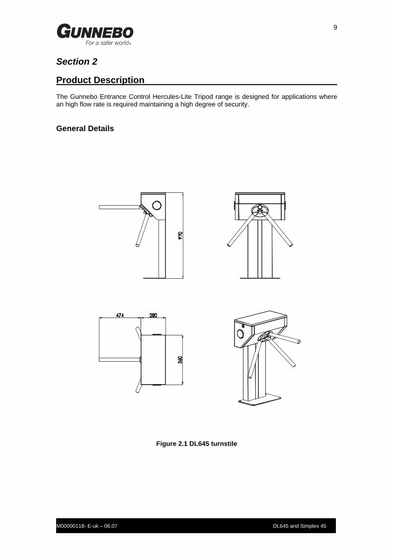
Section 2 Product Description The Gunnebo Entrance Control Hercules-Lite Tripod range is designed for applications where an high flow rate is required maintaining a high degree of security.
General Details
Figure 2.1 DL645 turnstile
10
M00000118- E-uk – 06.07 DL645 and Simplex 45
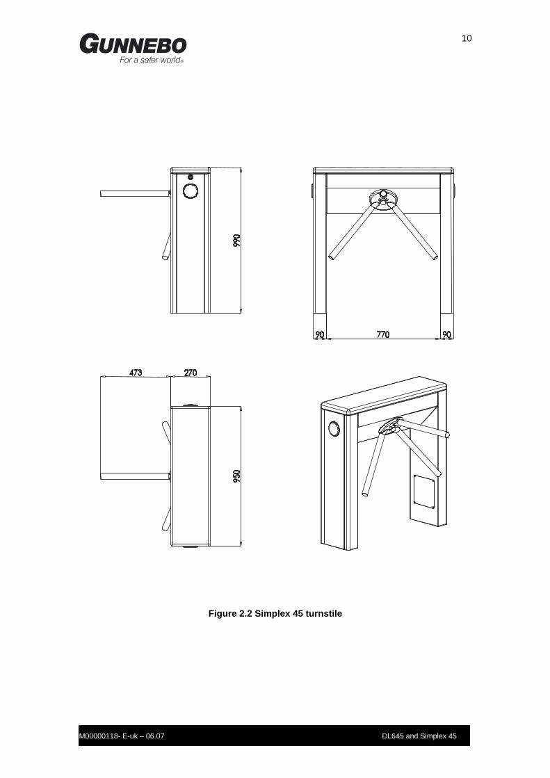
Figure 2.2 Simplex 45 turnstile

11
M00000118- E-uk – 06.07 DL645 and Simplex 45
Figure 2.3 Simplex 45 ATT turnstile

12
M00000118- E-uk – 06.07 DL645 and Simplex 45
Technical Details The Hercules-Lite turnstile consists of stainless steel cabinet which dimensions and shape depend on the model. The cabinet contains and supports the mechanism that controls the rotation of a Head Assembly that has three tubular arms. These arms are positioned at 120° intervals so that when the unit is at rest one arm will always be in the horizontal position – BARRIER POSITION. The movement of the head assembly is controlled by two solenoid devices, which allow rotation in both directions. The passageway can be controlled by devices such as card readers, or local and remote push buttons. The head assembly is moved manually by the person using the turnstile.
Technical Specification Orientation: Pass Left or Pass Right Drive: Hand Operated Material: Stainless steel AISI 304 Scotch-BriteTM finished Casework Lid Standard stainless steel AISI 304 Scotch-BriteTM
finished Hercules-Lite Tripod Hub: Cast Aluminium with grey finish. Hercules-Lite Tripod Arms: 38mm diameter 480mm AISI 304 polished stainless
Steel with welded end caps. Function: Passage in both directions, electronically controlled. Mechanism: Control of the Hercules-Lite Tripod operation is
achieved by an electro- mechanical head mechanism located within the top section of the turnstile casework. The unit has the following features as standard:
Normally Closed – The mechanism is locked until a valid authorisation signal is received.
Normally Open – The mechanism is permanently unlocked and will only lock if passage is attempted without a valid authorised signal. In this mode the MTBF is increased from 1.5 to 2.5 million cycles and increases passage through-put speed.
Power Supply: 115/230 Vac 50/60Hz
13
M00000118- E-uk – 06.07 DL645 and Simplex 45
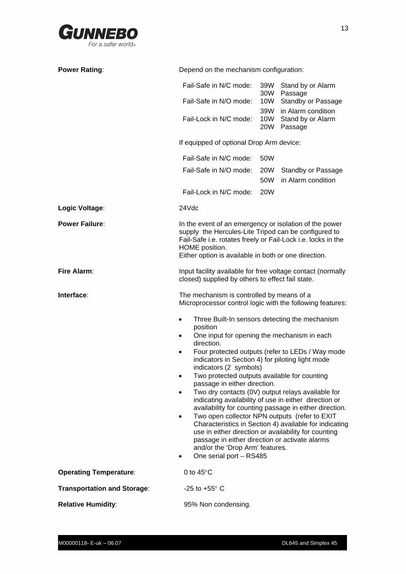
Power Rating: Depend on the mechanism configuration:
Fail-Safe in N/C mode: 39W Stand by or Alarm 30W Passage Fail-Safe in N/O mode: 10W Standby or Passage 39W in Alarm condition Fail-Lock in N/C mode: 10W Stand by or Alarm 20W Passage
If equipped of optional Drop Arm device: Fail-Safe in N/C mode: 50W
Fail-Safe in N/O mode: 20W Standby or Passage 50W in Alarm condition
Fail-Lock in N/C mode: 20W Logic Voltage: 24Vdc Power Failure: In the event of an emergency or isolation of the power
supply the Hercules-Lite Tripod can be configured to Fail-Safe i.e. rotates freely or Fail-Lock i.e. locks in the HOME position. Either option is available in both or one direction.
Fire Alarm: Input facility available for free voltage contact (normally
closed) supplied by others to effect fail state. Interface: The mechanism is controlled by means of a
Microprocessor control logic with the following features:
• Three Built-In sensors detecting the mechanism position
• One input for opening the mechanism in each direction.
• Four protected outputs (refer to LEDs / Way mode indicators in Section 4) for piloting light mode indicators (2 symbols)
• Two protected outputs available for counting passage in either direction.
• Two dry contacts (0V) output relays available for indicating availability of use in either direction or availability for counting passage in either direction.
• Two open collector NPN outputs (refer to EXIT Characteristics in Section 4) available for indicating use in either direction or availability for counting passage in either direction or activate alarms and/or the ‘Drop Arm’ features.
• One serial port – RS485 Operating Temperature: 0 to 45°C Transportation and Storage: -25 to +55° C Relative Humidity: 95% Non condensing.

14
M00000118- E-uk – 06.07 DL645 and Simplex 45
Section 3 Instruction for Use The information contained in this section should be used as a base for the instruction of personnel in the correct use of the Hercules-Lite Tripod Range of Barriers. The Hercules-Lite Tripod turnstile is unlocked by presenting a personalised identity card or device to the access control reader. (Supplied by others) It can also be unlocked by activating a casework or remote reception push button, if fitted. This will release the mechanism locking solenoids and render the Hercules-Lite Tripod ready for use by walking through the walkway passage in the desired direction. Should the user decide not to proceed with the passage, the locking solenoid will remain unlocked for a predetermined time after which it will ‘time out’ and reset the unit making it available for the next person.
Important Notices
• DO NOT try to push the rotor by hand as you walk through the barrier
• DO NOT walk through the barrier with large bags or briefcases in front or trailing behind you.
• DO NOT drag bags over the top casework. (Always lift bags over the top of the barrier).
Should any item become caught in the rotor, STOP, and DO NOT keep forcing through in the same direction.
Signs and Symbols In this manual the conventional signs shown in the Figure 3.1 will be employed. Direction A is the direction where the mechanism (or the rotor’s cabinet) is to the right when passing through the turnstile.
Figure 3.1 Schematic Diagram of the Unit.
Head Assembly
Direction A Direction B
Solenoid A Solenoid B

15
M00000118- E-uk – 06.07 DL645 and Simplex 45
Operating Modes The Hercules-Lite Tripod turnstile is bi-directional. The two directions can be separately configured as follows:
• Unlock mode: passage is authorised for all users in the desired direction;
• Lock mode: passage is inhibited in the desired direction;
• Reader control mode: the passage is possible only for those users who are recognised by the badge reader.
The mode for each direction can be set by means of:
• setting of the control logic trimmers position (see Section 8 - table 8.7);
• remote control (optional Gunnebo Entrance Control MP2000 control module);
• RS485 serial interface (through the Gunnebo Entrance Control proprietary serial protocol).
The action of the Remote Control or the Serial Control has priority over the trimmers position setting. The HERCULES locking device can be supplied in two versions that can be factory or site set:
• (FL) Fail Locked – mechanism locked in the absence of the power supply;
• (FS) Fail Safe – mechanism released in the absence of the power supply.
In consequence of this mechanical setting, a trimmer of the LL2001 electronic board must be adjusted as described in Section 8, table 8.1. Within these versions the control logic offers two operating modes: Normally Closed - Controlled Transit in Standard Mode (STD) At rest the rotary unit is locked. On receipt of an authorisation signal from the reader unit, the solenoid releases rotation in the required direction. Normally Open – Controlled Transit in Permanently Open Mode (SA) At rest the rotary unit is unlocked and free to rotate in both directions. An attempt to turn the arm without the due authorisation will activate the solenoid and block rotation. Note - The solenoids can be configured for both FL and FS operation. The required operating mode can be selected by setting the appropriate Trimmer position.
Normally Closed Transit Sequence At rest, rotation is prohibited in both directions and solenoids ‘A’ and ‘B’ will be de-energised in the FL configuration (energised in FS mode).

16
M00000118- E-uk – 06.07 DL645 and Simplex 45
If the authorisation signal enabling transit in direction ‘A’ is received from the reader unit, rotation will be released in that direction (‘A’ energised in FL – de-energised in FS) To lock the Hercules-Lite Tripod on completion of rotation, the locking arm is recalled (‘A’ de-energised in FL or energised in FS) when the Hercules-Lite Tripod has rotated approximately 67O from the starting point. During the entire rotation solenoid ‘B’ remains de-energised in FL configuration (energised in FS) in order to perform the anti-reversal function. The system operates in the same manner for transit in direction ‘B’.
Normally Open Transit Sequence At rest, rotation is not prevented by the solenoids that are energised in the FL configuration (de-energised in FS) If a person attempts to rotate the Hercules-Lite Tripod in direction ‘A’ without authorisation having been received from the reader unit – solenoid A will lock the Hercules-Lite Tripod after it has rotated approximately 10O. Only when the Hercules-Lite Tripod has returned to the BARRIER position will the rocker arm release. Note - The same action applies for direction ‘B’. During transit in any direction, if an attempt is made to reverse the Hercules-Lite Tripod the anti-reversal device will only intervene if the Hercules-Lite Tripod has already completed a rotation of 670 in the authorised direction. The anti-reversal device operates when the control logic detects a rotation of approximately 3.3O in the opposite direction to that authorised. Solenoid ‘B’ will operate if the authorised direction is ‘A’ or vice-versa. The solenoid releases the rocker arm only when the Hercules-Lite Tripod is rotated a further 6.6O in the authorised direction.
Emergency / Fire Alarm The Hercules-Lite turnstile offers an input (normally closed) in order to receive an Emergency / Fire Alarm remote command (by other). When this command is active, the control logic releases the rotation of the tripod in both directions. This condition will remain for the duration of the signal being received by the control logic. If the turnstile is equipped of optional drop arm device, when the command is active, the arm in the barrier position is released in order to leave the passageway open. Connection details are given in Section 5 of this manual.
Traffic Lights and Pictograms In order to facilitate the transit flow, optional traffic lights and pictograms are available which show when a turnstile is programmed with the lock mode or is already engaged in the other direction (red cross). Similarly the presence of a green arrow indicates that a user can pass through the turnstile. In case of pictogram, an additional card reader sign indicates that the entrance is ready to accept the access control system authorization. If this optional are used, a trimmer of the LL2001 electronic board must be properly configured (see Section 8 – table 8.5).
17
M00000118- E-uk – 06.07 DL645 and Simplex 45
Alarms If a person attempts to rotate the Hercules-Lite Tripod without authorisation having been received from the reader unit the control logic will interpret this as an attempt at fraud (‘Fraud’ alarm). In the SA mode the solenoid locks rotation. The rocker arm is released when the Hercules-Lite Tripod returns to the BARRIER position. In every case, the tripod rotation must be completed within 8 seconds from the leaving of the BARRIER position, otherwise the control logic will signal an alarm (‘Positioning’ alarm). The alarm is reset when the Hercules-Lite Tripod returns to the BARRIER position. If the Hercules-Lite is equipped of Drop Arm device, the control logic detects if the arm in barrier position is dropped. In that case, the control logic will signal an alarm (‘Drop Arm’ alarm). The alarm is reset when the arm is restored in the barrier position. The Simplex 45 ATT model is equipped of two photocells and/or a sensitized top lid in order to recognise the attempts of cross the barrier without authorization. If these sensors are activated when the control logic is not processing any authorized rotation, an alarm will be triggered. That alarm is reset 3 seconds after the sensors de-activation. The photocells alarm is automatically inhibited when the Unlock operating mode is set for, at least, one direction. In that case, only the sensitized top lid alarm is active. During all the described alarm conditions, the control logic locks the rotating head and signals that status by means of the buzzer activation, the flashing red cross on the traffic lights and activating a dry contact output. By means of a trimmer (see Section 8 – table 8.8). it is possible to choice which alarm has to be signalled by the dry contact output.
Remote Control interface The Hercules-Lite turnstile control logic offers an electrical interface in order to allow the remote control of entrance. By means of the optional Gunnebo Entrance Control MP2000 control module, the operation modes of the unit can be set by a remote consol (see connection details is Section 5 of this manual). In case the remote control is needed, a trimmer of the LL2001 must be set as described in Section 8 – table 8.7.
RS485 Serial Line The Hercules-Lite turnstile control logic can be interfaced with RS485 serial line using the Gunnebo Entrance Control proprietary protocol. In this way the operating modes, alarms and transit information are available for full integration with the access control system. In case the serial line connection is used, a trimmer of the LL2001 must be set as described in Section 8 – table 8.7. If more than one Hercules-Lite turnstile unit must be connected to the same bus, it is possible to assign an address to each one by means of the dip-switches mounted on the LL2001 electronic board. Up to 16 units can be addressed into the bus (see section 8 - table 8.9 for addresses assignment). The description of the proprietary protocol can be required to the Technical Support; connection details are available in Section 5 of this manual. In order to improve the interfacing capability of the serial line, it is possible to slow down the transmission flow from the Hercules-Lite turnstile’s serial port by means of a trimmer mounted on the LL2001 electronic board (see section 8 – table 8.3).

18
M00000118- E-uk – 06.07 DL645 and Simplex 45
Programmable Parameters and Trimmers The Hercules-Lite turnstile operational modes are affected by the positions of the eight trimmers mounted on the LL2001 board; their functionality is resumed in Section 8 of this manual. When the control logic microprocessor executes the resident program it consults the current position of the trimmers in order to set the timings of certain actions and internal algorithms. Note
• When ONE or MORE trimmer position is changed, it will be necessary to press the RESET Button on the LL2001 Board.
• Modifications to the trimmers setting should only be carried out by trained personnel.
• When the trimmers setting is changed, it is important to record the new and the old configuration.
Reader Authorization Signal Management In the Reader-Controlled Mode, the logic system waits for the card reader to send an unlock signal that authorizes passage. The signal sent by the reader can be interpreted in three ways.
• Unlock on Front: the logic identifies as authorisation the transition from non active to active (of the unlock signal). In this moment the logic starts to count down the transit time out;
• Unlock on Level: the logic identifies as authorisation the transition from active to non active (of the unlock signal). In this moment the logic starts to count down the transit time out;
• Copy: the logic keeps the system unlocked for a period corresponding to when the reader signal is sent.
Operate the choice by means of a trimmer mounted on the LL2001 electronic board (see section 8 – table 8.2). The “Unlock on Front” mode is set by default from factory. In this modality, the logic records authorisation signals that arrive while the door is still being used. The maximum number of authorisation signals that can be recorded is determined by the TR4 trimmer position. See also section 5 for connection details.

19
M00000118- E-uk – 06.07 DL645 and Simplex 45
Counting pulse and other output signals The electrical outputs of the LL2001 control board are available to interface the Hercules-Lite turnstile to the ticket readers and the surrounding systems. To obtain the most flexible signals interface, a logic function attributed to each one of these outputs can be set with by means of the LL2001 trimmers setting. The available outputs are listed below (electrical details in Section 4):
id description connector / pin assignment trimmer
REL1 dry contact relay USER-INT pin 6, 7 TR8
REL2 dry contact relay (NC/NO) OUT-CRD pin 1, 2 TR5
REL3 dry contact relay (NC/NO) OUT-CRD pin 3, 4 TR5
auxiliary output 1 npn open collector OUT-AUX pin 2 TR6
auxiliary output 2 npn open collector OUT-AUX pin 3 TR6
LIGHT-A pin 4 npn open collector (*) LIGHT-A pin 4 TR5
LIGHT-B pin 4 npn open collector (*) LIGHT-B pin 4 TR5 (*) available when pictograms are not used. The available logic functions are listed below:
‘counting pulse’: It acknowledges the occurred transit in one direction. An output is available for each passage direction. The pulse is generated every time the rotor reaches an half or full rotation angle (the choice is made by the TR4 trimmer). The duration of the counting pulse can be chosen between two values by means of the TR3 trimmer.
‘enable reader’: It signals when the logic is ready to accept authorizations from the card reader in one direction. An output is available for each passage direction. If the entrance is not configured in the Reader-Controlled Mode or is in some alarm condition, the ‘enable reader’ signal is off.
‘presence of power’: It signals that the gate is powered on.
‘alarms’: It signals an alarm condition with the permanent activation of the output.
‘buzzer’ It signals an alarm condition with the intermittent activation of the output

20
M00000118- E-uk – 06.07 DL645 and Simplex 45
Section 4 Technical Information
Components Location Figure 4.1 shows the general location of the main units that comprise the Hercules-Lite Tripod.
Figure 4.1 Layout Details of Hercules-Lite Tripod Units
Note
• All items shown are accessible with the lid removed. • PSU‘s can be configured as 230V or 110Vac. • Remote control is by means of the USER-INT Controller
Hercules Head Mechanism
Drop Arm Sensor
LL2001
Damper
Restoring Spring
Drop Arm Mechanism Power Supply Unit

21
M00000118- E-uk – 06.07 DL645 and Simplex 45
Hercules Mechanism Construction Note - The references shown as (2) (3) (4) refer to the item numbers detailed in the Parts List.
Figure 4.2 Head Mechanism Details
Die Cast Base An aluminium alloy base, provides mountings and guides for the components of the head mechanism. Two bearings for the shaft (02) are pressed into housings in the base.
Rotary Unit The unit comprises a shaft (02) toothed cam assembly and upper positioning cam (07). The toothed cam assembly comprises a steel toothed cam (04) polyurethane toothed cam (05) and locking flange (06) that are bolted together with bolts and spacers (28). The shaft is inserted into the toothed cam assembly, secured by a key (71). The upper cam is attached to the top of the toothed cam assembly by three screws (52). The nut (60) screws onto the threaded end of the shaft and secures the shaft to the cams. The other two sensors, mounted on the copper side of the board, generate a pair of electrical signals as the solenoids of the ferrite strip pass the sensors.
(Optional) Drop Arm Sensor
Timing Disc
LL2001 Card location (removed for clarity)
Locking Solenoid (shown in Fail Safe set up)
Damper/Restoring Arm
Restoring SpringDamper
Restoring Spring tension adjuster
Locking Pawl
Locking Solenoid (shown in Fail Lock set up)
22
M00000118- E-uk – 06.07 DL645 and Simplex 45
Figure 4.3 Head Mechanism Cross Section Details
Locking Device The locking action is performed by the heads of the rocker arms (08) on the teeth of the toothed cam assembly. The polyurethane toothed cam, which is part of the toothed cam assembly, reduces the noise produced by the action of the rocker arms on the cam teeth. Cam profile is designed so that the shaft rotation may be locked at 15O intervals. The rocker arms are pivot-mounted on the bases and are moved by the moving cores of two solenoids (22) mounted to the base. One of the solenoids locks clockwise, the other anti-clockwise rotation. The locking device is available in two version: FL, locks the turnstile in the absence of the power supply. FS, releases the turnstile in the absence of the power supply. In the FL version, activation of the solenoid causes the rocker arm to move and disengage the cam teeth. The turnstile is therefore free to rotate in one direction. When the solenoid is de-energised, the rocker arm is returned to the locking position by the action of a spring (41). In the FS version, activation of the solenoid causes the rocker arm to move to engage to the cam teeth and prevent turnstile rotation in one direction. When the solenoid is de-energised, the rocker arm is returned to the released position by the action of the spring. The force exerted by the rocker arm springs can be adjusted by screw (56).
3NO Hub fixing bolts
Tripod Arm
Arm fixing
Arm Pivot casting
Drop Arm LeverDrop Arm Activation Pin
Timing Disc Sensing Magnets
LL 2001 Board
Locking Pawl
Drop Arm Solenoid assembly
Hub
Anti vibration mounts
Base plate casting
Ratchet block assembly
23
M00000118- E-uk – 06.07 DL645 and Simplex 45
Positioning Device The upper positioning cam consists of a nylon disc, in which is machined a guide way with a special profile. In this guide way, three points at a minimum distance from the centre are arranged at 120O intervals and correspond to the three positions of the Hercules-Lite Tripod. A notch in the cam engages and guides pin (18) on the end of the positioning lever (10). The lever hinges on the pivot (11), mounted on the base (01). The lever also mounts pins (25) and (29) for positioning spring (21) and the damper (33). The other ends of the spring and the damper are pivot-mounted on the base. Once the guide pin has travelled past the apex in the cam guide way, the action of the spring causes the rotary unit to rotate a full 120O, thereby returning the Hercules-Lite Tripod to the barrier position. The tension of the positioning spring can be adjusted by screw (17).
Damper The function of the damper is to adjust the force exerted by the spring on the rotary unit in order to ensure that the unit comes to a gentle stop. During the first half of rotation (rising profile in the guide way) the damper expands and in the second half (falling profile), it contracts. During the entire rotation, the damper exerts a braking force in proportion to the rotation speed.
Anti Reversal Device The anti-reversal device is used to prevent rotation of the rotary unit in the opposite direction to that of the initial rotation. This means that once the Hercules-Lite Tripod has been moved in one direction, the device will prevent a reverse movement in the opposite direction. This function (like the locking function) is achieved by the action of the rocker arm heads on the teeth of a toothed cam assembly. The anti-reversal action is applied by solenoid A, if the initial direction of rotation is B and by solenoid B if the initial direction of rotation is A. The anti-reversal device comes into effect after the unit has rotated through 67O, in this case the mechanism locks the nearest of the following angular positions 60O, 75O, 90O and 105O.
Positioning Sensors The mechanism is equipped with Sensors and Sensor Actuators to determine the angular position of the rotary unit.
Sensor Actuators The radial ribs of the upper positioning cam contain three magnets. The ends of these solenoids are flush with the edge of the cam and are positioned at 120O intervals, in line with the three barrier positions of the Hercules-Lite Tripod. A ferrite strip is attached to the top of the cam and acts as a series of permanent magnets arranged alternately at 10mm intervals, giving a total of 54 dipoles along the entire circumference of the cam.

24
M00000118- E-uk – 06.07 DL645 and Simplex 45
Sensors As the upper positioning cam rotates it follows the semi-circular profile of the LL 2001 electronic circuit board, on to which is mounted three magnetic field sensors.
Tripod Comprises a base plate to which are mounted the arm mountings and position sensing devices. The stainless steel arms are positioned at 120O intervals, so that when the Hercules-Lite Tripod comes to rest, one of the arms will be in the barrier position. Each arm is attached to its mounting by cones inserted inside the arm and tightened by a nut and bolt. The arm mountings are pivot-mounted on the base plate by pins and bushes. Arm mountings are attached to the base plate by a tooth that engages a detent. The detents are held in position by the springs and the arms can be released by operating the detent release pins, The system means that the mechanism can be fitted with an emergency arm drop device. The Hercules-Lite Tripod is secured to the shaft by three M10x20 hex socket screws. Fitted with locking compound and tightened to 60Nm.
Static Hub Version Figure 4.4 shows a Typical Static Hub that can be supplied when the Emergency Drop Arm option is not requested. For an Emergency, the Hub can be configured to a FREE WHEEL condition - allowing free passage (FS in both directions).
Figure 4.4 Static Hub

25
M00000118- E-uk – 06.07 DL645 and Simplex 45
Emergency Drop Arm Device (Optional) The mechanism can be supplied with an emergency drop arm device that in the event of a power failure (or in response to a remote command) releases the Hercules-Lite Tripod arm that is in the barrier position The arm drops under its own weight to leave the passageway open. The device consists of a lever which pivots on the base plate, as well as a solenoid, which operates the lever. In the normal conditions, the solenoid is permanently energised. When the device is activated, the solenoid is de-energised and spring acts on the lever, to operate the arm detent release pin. The position of the solenoid and therefore the angular position of the release lever can be adjusted by unscrewing the screws. A sensor monitors the position of the arm (barrier position or lowered) and passes the signal to the control logic.
Figure 4.5 Drop Arm Components
Hercules-Lite Tripod Arm
Arm Pivot casting
Drop Arm Activation and Pin assembly
Drop Arm Activation Lever
Drop Arm Solenoid Assembly
Hub Baseplate
(cut through for clarity)
Drop Arm Linkage Pivot
26
M00000118- E-uk – 06.07 DL645 and Simplex 45
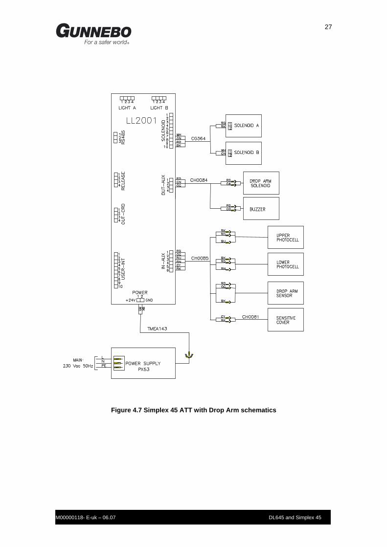
Electrical Schematics
Figure 4.6 DL645 and Simplex 45 with Drop Arm schematics
27
M00000118- E-uk – 06.07 DL645 and Simplex 45
Figure 4.7 Simplex 45 ATT with Drop Arm schematics

28
M00000118- E-uk – 06.07 DL645 and Simplex 45
Figure 4.8 Traffic Lights and Pictograms connections
Figure 4.9 Service Counters connection
A
29
M00000118- E-uk – 06.07 DL645 and Simplex 45
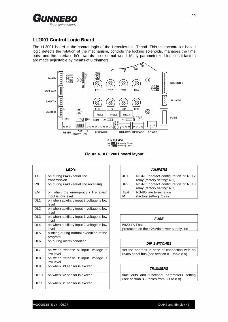
LL2001 Control Logic Board The LL2001 board is the control logic of the Hercules-Lite Tripod. This microcontroller based logic detects the rotation of the mechanism, controls the locking solenoids, manages the time outs and the interface I/O towards the external world. Many parameterized functional factors are made adjustable by means of 8 trimmers.
TR1 TR2 TR3 TR4
TR5 TR6 TR7 TR8
S1S2
S3RES
IN-AUX
OUT-AUX
LIGHT-A
LIGHT-B
1
1
1
1
DL3DL4DL1DL2
RS485 DIPSWITCHES
USER-INT OUT-CRD
REL1 REL2 REL3
RELEASE POWER
FUSE
SRV-CNT
SOLENOID
11 1 1
1
1
TX RX EM JP1 JP2DL6
DL5
DL7 DL8
DL9DL10DL11
PRO
G
NC Normally CloseNC Normally Open
JP1 and JP2:
TERM
Figure 4.10 LL2001 board layout
LED’s JUMPERS
TX on during rs485 serial line transmission
JP1 NC/NO contact configuration of REL2 relay (factory setting: NO)
RX on during rs485 serial line receiving JP2 NC/NO contact configuration of REL3 relay (factory setting: NO)
EM on when the emergency / fire alarm input is low level
TERM
RS485 line termination (factory setting: OFF)
DL1 on when auxiliary input 3 voltage is low level
DL2 on when auxiliary input 4 voltage is low level
DL3 on when auxiliary input 1 voltage is low level
FUSE
DL4 on when auxiliary input 2 voltage is low level
5x20 1A Fast; protection on the +24Vdc power supply line
DL5 blinking during normal execution of the program
DL6 on during alarm condition DIP SWITCHES
DL7 on when ‘release A’ input voltage is low level
set the address in case of connection with an rs485 serial bus (see section 8 – table 8.9)
DL8 on when ‘release B’ input voltage is low level
DL9 on when S3 sensor is excited TRIMMERS
DL10 on when S2 sensor is excited time outs and functional parameters setting (see section 8 – tables from 8.1 to 8.8)
DL11 on when S1 sensor is excited
30
M00000118- E-uk – 06.07 DL645 and Simplex 45
The main features of the GC01 board are listed below:
Microcontroller: Motorola MC68HC908AB32 (based on 8-bit microprocessor HC08 family); 32 Kbytes Flash IS programmable; 1 Kbytes RAM; 512 bytes EEPROM clock 4.91Mhz.
Interfaces: Half duplex RS485;
Power: 24Vdc;
Inputs: 14 TTL type;
Outputs: 3 dry contact (2 of them NO/NC configurable); 11 open collector npn;
Other: 1 push button (hard reset); 8 trimmer for parameters setting.
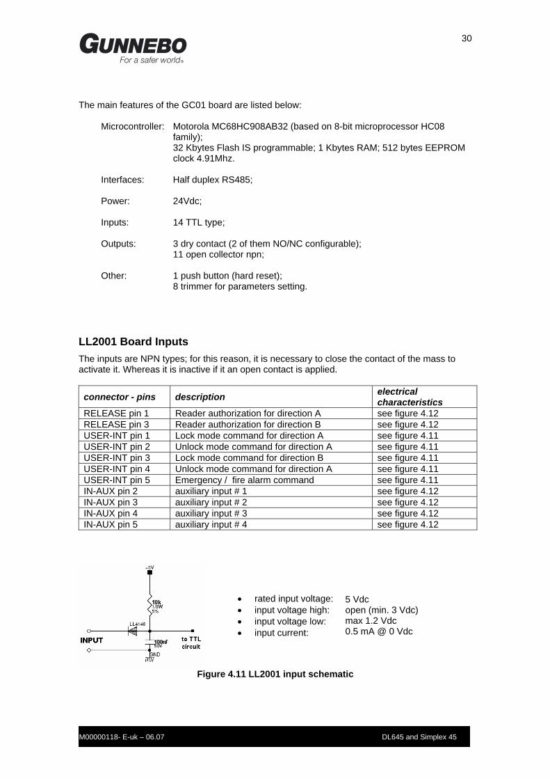
LL2001 Board Inputs The inputs are NPN types; for this reason, it is necessary to close the contact of the mass to activate it. Whereas it is inactive if it an open contact is applied.
connector - pins description electrical characteristics
RELEASE pin 1 Reader authorization for direction A see figure 4.12 RELEASE pin 3 Reader authorization for direction B see figure 4.12 USER-INT pin 1 Lock mode command for direction A see figure 4.11 USER-INT pin 2 Unlock mode command for direction A see figure 4.11 USER-INT pin 3 Lock mode command for direction B see figure 4.11 USER-INT pin 4 Unlock mode command for direction A see figure 4.11 USER-INT pin 5 Emergency / fire alarm command see figure 4.11 IN-AUX pin 2 auxiliary input # 1 see figure 4.12 IN-AUX pin 3 auxiliary input # 2 see figure 4.12 IN-AUX pin 4 auxiliary input # 3 see figure 4.12 IN-AUX pin 5 auxiliary input # 4 see figure 4.12
• rated input voltage: • input voltage high: • input voltage low: • input current:
5 Vdc open (min. 3 Vdc) max 1.2 Vdc 0.5 mA @ 0 Vdc
Figure 4.11 LL2001 input schematic

31
M00000118- E-uk – 06.07 DL645 and Simplex 45
• rated input voltage: • input voltage high: • input voltage low: • input current:
5 Vdc open (min. 3 Vdc) max 1.2 Vdc 8 mA @ 0 Vdc
Figure 4.12 LL2001 input with LED schematic
LL2001 Board Outputs
connector - pins description electrical characteristics
USER-INT pin 6, 7 REL1 dry contact see figure 4.13 OUT-CRD pin 1, 2 REL2 dry contact (NC/NO settable by jumper) see figure 4.14 OUT-CRD pin 3, 4 REL3 dry contact (NC/NO settable by jumper) see figure 4.14 SOLENOID pin 8 solenoid A driving output see figure 4.15 SOLENOID pin 10 solenoid B driving output see figure 4.15 OUT-AUX pin 2 auxiliary output 1 see figure 4.15 OUT-AUX pin 3 auxiliary output 2 see figure 4.16 LIGHT-A pin 2 pictogram A: ‘red cross’ sign see figure 4.17 LIGHT-A pin 3 pictogram A: ‘badge’ sign see figure 4.17 LIGHT-A pin 4 pictogram A: ‘green arrow’ sign see figure 4.17 LIGHT-B pin 2 pictogram B: ‘red cross’ sign see figure 4.17 LIGHT-B pin 3 pictogram B: ‘badge’ sign see figure 4.17 LIGHT-B pin 4 pictogram B: ‘green arrow’ sign see figure 4.17 SRV-CNT pin 2 service counter output see figure 4.17
.
• ratings:
• max. switched voltage: • max. switched current: • max switched power:
1A @ 24 Vdc resistive, 1A @ 120 Vac resistive AC: 120 V ; DC : 60 V 1 A 120 VA ; 30 W
Figure 4.13 LL2001 NO dry contact output
• ratings:
• max. switched voltage: • max. switched current:
max switched power:
1A @ 24 Vdc resistive, 1A @ 120 Vac resistive AC: 120 V ; DC : 60 V 1 A 120 VA ; 30 W
Figure 4.14 LL2001 NC/NO dry contact output

32
M00000118- E-uk – 06.07 DL645 and Simplex 45
• ratings: • max. On voltage:
3 A @ 24 Vdc 39 mV @ 3 A
Figure 4.15 LL2001 npn open drain MOSFET output
• ratings: • max. saturation voltage
2A @ 24 Vdc 1.6 V @ I = 1.4A
Figure 4.16 LL2001 npn ‘Darlington’ open collector output
• ratings: • max. saturation voltage:
500 mA @ 24 Vdc 1.6 V @ I = 350 mA
Figure 4.17 LL2001 npn ‘Darlington’ open collector output
LL2001 Board Connectors
IN-AUX OUT-AUX
type: Amp Modu II (male) 6 positions
type: Amp Modu II (male) 4 positions
Pin Signal Pin Signal 1 +24 Vdc output 1 +24 Vdc output 2 auxiliary input # 1 2 auxiliary output # 1 3 auxiliary input # 2 3 auxiliary output # 2 4 auxiliary input # 3 4 GND 5 auxiliary input # 4 6 GND

33
M00000118- E-uk – 06.07 DL645 and Simplex 45
LIGHT-A LIGHT-B
type: Amp Modu II (male) 4 positions
type: Amp Modu II (male) 4 positions
Pin Signal Pin Signal 1 +24 Vdc output 1 +24 Vdc output 2 picto A: ‘red cross’ sign 2 picto B: ‘red cross’ sign 3 picto A: ‘badge’ sign 3 picto B: ‘badge’ sign 4 picto A: ‘green arrow’ sign 4 picto B: ‘green arrow’ sign
RS485
type: Sauro CTM (male) 3.5mm pitch, 3 positions; + CTF (female) terminal block for wire diameter: 0.05÷1.5mm2 (30÷16 AWG)
Pin Signal 1 data- : low signal of the rs485 serial line 2 data+ : low signal of the rs485 serial line 3 GND : mass filtered by a 22 uH inductance
USER-INT OUT-CRD
type: Sauro CTM (male) 3.5mm pitch, 10 positions; + CTF (female) terminal block for wire diameter: 0.05÷1.5mm2 (30÷16 AWG)
type: Sauro CTM (male) 3.5mm pitch, 4 positions; + CTF (female) terminal block for wire diameter: 0.05÷1.5mm2 (30÷16 AWG)
Pin Signal Pin Signal 1 Lock mode input for direction A 1 REL2 common contact 2 Unlock mode input for direction A 2 REL2 NO contact 3 Lock mode input for direction B 3 REL3 common contact 4 Unlock mode input for direction A 4 REL3 NO contact 5 Emergency / fire alarm input 6 REL1 common contact 7 REL1 NO contact 8 +12 Vdc output 9 GND
10 +24 Vdc output
RELEASE POWER
type: Sauro CTM (male) 3.5mm pitch, 4 positions; + CTF (female) terminal block for wire diameter: 0.05÷1.5mm2 (30÷16 AWG)
type: PA253 HO/C (male) 5mm pitch, 2 positions + PA252 (female) terminal block for wire diameter: 0.08÷2.5mm2 (28÷14 AWG)
Pin Signal Pin Signal 1 Authorization input for reader A 1 GND 2 GND 2 + 24 Vdc power supply input 3 Authorization input for reader B 4 GND

34
M00000118- E-uk – 06.07 DL645 and Simplex 45
SRV-CNT SOLENOID
type: Amp Modu II (male) 4 positions
type: Amp Modu II (male) 10 positions
Pin Signal Pin Signal 1 +24 Vdc output 1 do not use 2 service counter output 2 do not use 3 not used 3 do not use 4 GND 4 GND 5 +5 Vdc output 6 +24 Vdc output 7 +24 Vdc output 8 A solenoid driving output 9 +24 Vdc output 10 B solenoid driving output
Power supply unit The PX53-14A power supply unit supplies 24 V dc power for the electronic and the mechanism’s electro-mechanical devices. The unit is fitted with an ON/OFF switch and a socket for the connection to the power supply network. The main characteristics are:
Input voltage:
115/230Vac, 50/60Hz
Output voltage:
24Vdc
Max current:
2.2 A
Power:
50 watt
Input protection:
Internal fuse 5x20mm, 4 A/250V
Output protection: Automatic for current and voltage overloads

35
M00000118- E-uk – 06.07 DL645 and Simplex 45
Section 5 Installation
Unpacking On receipt of equipment on site, check all items are complete and undamaged. If for any reason transit damage has occurred, ensure the extent of any damage is recorded and if considered necessary report the incident to Gunnebo Entrance Control. Retain all major component packaging for re-use in the event that items may need to be returned for servicing during their life.
Tools required - Hammer drill, with masonry drills (12mm for EAM 10 expansion fittings, or 20mm for M
10 expansion fittings)
- Screwdrivers set
- Socket head screwdriver
- Box wrench set
- Wire cutters
- Crimping Pliers
- Wire strippers
- Insulated lugs
- Piece of string, chalk powder, pen
- Scissors
- Double tape measure
- Rubber mallet
- Level
- Lid Lock Key
- Lifting equipment
NOTE: The lifting equipment should be appropriate for the weight of the barrier, and characteristics of the assembly site. The weight of Turnstile barrier is approximately 70 kg.
Please read all sections carefully before commencing the installation
Site Preparation Before assembly the following aspects should be taken into consideration:
Environmental conditions; Power supply characteristics; Physical space; Cable layout.
Environmental conditions For the correct operation of the equipment the site should meet the following requirements:

36
M00000118- E-uk – 06.07 DL645 and Simplex 45
Working temperature: 0 - + 45 °C; Humidity must not exceed 95%; THE TURNSTILE MUST BE NOT EXPOSED TO DIRECT SUN-LIGHT OR RAIN. There must be no solid, liquid or gaseous pollutants present that could corrode copper or other metal components of the equipment. This equipment can not be used in potentially explosive atmospheres.
Power Supply Characteristics Hercules-Lite turnstiles operate from the public power supply network. Nominal voltage required: 230-115 Vac / 50-60 Hz . Tolerance is ±15% of the nominal value. Maximum power supply of the equipment is 50 W. The power must be supplied through a dedicated cable NOT from cables that supply other electrical equipment. In the event of voltage or frequently variations the use of voltage stabilisers is advisable. The power supply circuits of the equipment must be protected by disconnecting switches that are independent from other machinery. The power supply circuits provided by the customer must have an insulated conductor for grounding, with the same section of the phase conductor, at least. The earth protection circuit must be equipotential and comply with all safety standard in force. For installations in areas particularly prone to thunderstorms, or supplied by overhead power lines, it is recommended to install an anti-lightning protector on the power supply line.
General Conditions Before assembling the equipment, it is recommended the drawing of the installation site lay-out, referring to Lay-out drawings (Figure 5.2 – 5.3) shown in this Manual. This equipment can not be installed along escape routes or obstructing emergency exits. Ramped floor down to Hercules-Lite turnstile are potential hazard and shall be avoided. It is important to establish predicted user characteristics and volume of pedestrian traffic that is likely to pass through the installation. The installation and its immediate environment shall be designed and arranged to promote safe pedestrian flow. Foundations should be in concrete of resistance class, at least, fck (cube) 30N/mm2. The foundation should be flat with a maximum tolerance of 5mm. Anchor holes in the floor for M10 expansion bolts, must be of a minimum depth of 100mm. The positioning tolerance should be 2mm and the holes drilled during the installation stages. For floors made of very compact materials (such as granite) use expansion fittings, Fischer type

37
M00000118- E-uk – 06.07 DL645 and Simplex 45
mod. EAM 10, or equivalent. For floors made of less compact materials (concrete) use expansion fittings, Fischer type mod. M10 L=80mm De=20mm. Chemical expansion fittings can be used where the floor characteristics require it. Use appropriate screws of the expansion fitting, according to the following table. Expansion fitting Screw EAM 10 Hexagonal screw 10x30, flat ring nut M10 Hexagonal screw 10x60, flat ring nut
Cabling Hercules-Lite turnstile requires two types of cables: Power supply cables Signal transmission cables The following instructions should be followed when laying cables:
Earth conduits with a diameter no less than 20mm; Lay the conduits for the power cables and those for data transmission cables separately. Lay the conduits away from high voltage cables or cables with radio-frequencies, electric motors and other machines. Place the conduits as far as possible from the barrier's anchor holes in the floor; Conduits must be directed towards the position for the cables on the barrier (see the layout shown in this section). The conduits must rise at least 50 mm from the foundation base. Cables must rise from the floor with a length that reaches the logic panel on the barrier top or to the integrated reader mounted on the barriers (at least 1.5 m). Taken care when running the cables because curves with tight radii can damage the cables. Use cable grommets to protect from cutting edges and cable-ties or similar in order to prevent cables wrenching. The following cables generally connect the Full-O-Stile barrier to the outside: Power Supply Cable
For each door a power supply cable with 3 conductors must be used, starting from the user switch gear and running to the power supply unit. The conductors' section must be determined according to the cable length and the power required. At least 0.75 mm2 (AWG18) section is recommended. It is recommended to install a disconnecting switch up-line of the power supply. A differential switch should also be installed in accordance with Local Regulations.
Remote Control Line
If there is a remote control panel, an electric shielded cable with eight (8) conductors must be provided for each gate, running from the logic board to the remote control panel. It includes also the Emergency / Fire Alarm

38
M00000118- E-uk – 06.07 DL645 and Simplex 45
command. The conductor section, must be determined according to the length L of the cable:
if L < 100 m use 0.33 mm2 (AWG22); if 100 m < L < 250 m use 0.5 mm2 (AWG20); if 250 m < L < 500 m use 0.8 mm2 (AWG18).
Emergency / Fire Alarm
If there is not the remote control but only the fire alarm command is needed, an electric shielded cable with two (2) conductors must be provided. For the conductor section, follow the same rules described for the remote control line.
Serial Communication Line
If the RS485 serial connection is provided (optional), the logic boards of each barrier must be connected one after the other with a data transmission cable. A twisted and shielded cable (FTP Cat. 5 ) should be used for the connection. The cable must be posed in independent canalization and the recommended maximal length is 500 m.
Badge Reader Connection Line
The customer should consult the data provided by the reader’s system supplier.
Mounting Details
Figure 5.1 General Indications for Foundation Plinth
Concrete Foundation Plinth of resistance class, at least, fck (cube) 30N/mm2 Plinth shall be flat within a maximum tolerance of 5mm
Conduit for Cables shall protrude at least 50mm above face of Foundation Plinth.
WARNING: DO NOT PLACE CABLES OR HORIZONTAL PIPES NEAR TO FIXING

39
M00000118- E-uk – 06.07 DL645 and Simplex 45
Figure 5.2 DL645 installation layout
Indicative floor anchorposition (drill during installation)
Conduit and cables to rise within shaded area
Wirings entry
40
M00000118- E-uk – 06.07 DL645 and Simplex 45
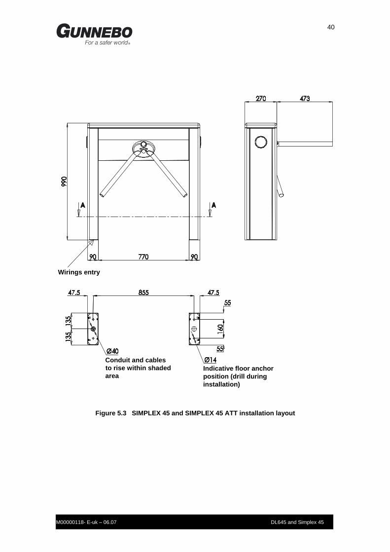
Figure 5.3 SIMPLEX 45 and SIMPLEX 45 ATT installation layout
Wirings entry
Conduit and cables to rise within shaded area
Indicative floor anchorposition (drill during installation)

41
M00000118- E-uk – 06.07 DL645 and Simplex 45
Unit Positioning The Hercules-Lite turnstile is supplied already-assembled and is tested in the factory before the shipping. The following details should be noted when planning the location of the Hercules-Lite Tripod unit. A gap of 50mm is left between the end of the main Hercules-Lite Tripod Arm and the nearest obstacle i.e. wall, barrier or even other entrance units. Allow 50mm to the rear of the Hercules-Lite Tripod to enable removal of the unit lid. An adjacent wall or barrier that is used for a walkway, must be at least 700mm long. If positioned next to another barrier ensure that it is not possible for a person to enter the walkway until the first person has passed through. The following guidelines are given to ensure that the Hercules-Lite Tripod is positioned correctly. Mark the floor fixing positions carefully as shown on the appropriate illustration. If the Hercules-Lite Tripod is to be installed as a multiple installation it is recommended that all fixing and conduit positions are marked and checked prior to drilling. Stand the Hercules-Lite Tripod over the marked positions and check that the bolt and conduit holes in the base of the unit match the floor markings. Check all clearances to adjoining Barriers or Wall. When satisfied that all is correct move the Hercules-Lite Tripod away and drill the floor. Fit the anchor bolts. Position the unit and feed cable tails through the respective holes in the base. Tighten the nuts and finally torque load to 40Nm.

42
M00000118- E-uk – 06.07 DL645 and Simplex 45
Electrical Connections All cables for the barrier should be placed as shown in the lay-out diagram and pass through the posts up to the top of the barrier and inserted in the logic board of the barrier.
Note : The following routine must be carried out by a qualified electrician.
Power Supply
Check the incoming mains supply is isolated. Feed the mains supply cable through the Hercules-Lite Tripod towards the MCB. Cut back and strip the sleeve as shown in Fig. 5.4 Connect the wires as shown in Fig. 5.4 Insert the VDE plug into the power supply unit socket.
Fig 5.4 Mains Power Electrical Power Preparation
INCOMING CABLE

43
M00000118- E-uk – 06.07 DL645 and Simplex 45
Connection with readers
NOTE (*) output signal depend on TR5 trimmer setting
Figure 5.5 Readers connection
MP2000 Remote Control Unit connection Fire Alarm command is included (the remote control unit must be equipped of additional module MP2500). If this input is not used, must be shorted to GND.
NOTES (*) additional MP2500 module is required (**) trimmer TR6 must be set in position 1 or 2 or 3
Figure 5.6 MP2000 connection

44
M00000118- E-uk – 06.07 DL645 and Simplex 45
Emergency / Fire Alarm
Figure 5.7 Emergency / Fire Alarm connection
RS485 Serial Line
Address Dip 1 Dip 2 Dip 3 Dip 4
1 OFF OFF OFF OFF 2 ON OFF OFF OFF 3 OFF ON OFF OFF 4 ON ON OFF OFF 5 OFF OFF ON OFF 6 ON OFF ON OFF 7 OFF ON ON OFF 8 ON ON ON OFF 9 OFF OFF OFF ON
10 ON OFF OFF ON 11 OFF ON OFF ON 12 ON ON OFF ON 13 OFF OFF ON ON 14 ON OFF ON ON 15 OFF ON ON ON 16 ON ON ON ON
Figure 5.8 RS485 serial line connection

45
M00000118- E-uk – 06.07 DL645 and Simplex 45
Section 6 Maintenance
General Care The Hercules-Lite Tripod should be cleaned and greased at regular intervals, using the following approved materials. Routine cleaning, all finishes Cleaning agent: Soap or mild detergent water. Action: Sponge rinse with clean water, wipe dry as necessary. Stubborn stains and discoloration, all finishes. Cleaning agent: Mild cleaning solutions or domestic service cleaners. Actions: Rinse well with clean water and wipe dry. Oil, Grease marks, all finishes Cleaning agent: Organic solvents (acetone, alcohol, genciene, trichlorethane). Action: Clean after with soap and water, rinse well with clean water and wipe
dry. Rust and other Corrosion products, Stainless finishes Cleaning agent: Oxalic acid. The cleaning solution should be applied with a swab and
allowed to stand for 15 to 20 minutes before being washed away with water. May continue using a domestic surface cleaner to give final clean.
Action: Rinse well with clean water (precautions for acid cleaners should be
observed). Minor scratches on painted surfaces Cleaning agent: Lightly rub with cutting paste. Rinse area with water and dry. Apply
touch-up paint in fine layers. Action: Allow 2 weeks to harden. Blend into surrounding paint work, using fine
cutting paste Deep scratches on painted finishes causing rust Cleaning agent: Remove rust with a small sharp knife. Apply rust inhibiting paint (red
oxide). Fill scratch with fine body filler to just under finished surface. Follow procedure for minor scratches.

46
M00000118- E-uk – 06.07 DL645 and Simplex 45
Greasing This action is carried out by the Service Engineer during service visits.
Routine Maintenance • General Indications The Hercules mechanism should be inspected and cleaned at regular intervals in order to maintain the components in good working order and to check for signs of wear. NOTE: The following information refers to a typical installation where the average number of transits per year is equal to ONE Million WARNING: To avoid the risk of electric shock, always ensure that the electrical power is disconnected before inspecting the mechanism. • Lubricants For the lubrication of parts subject to wear, use Molycote BR2 Plus® grease or an equivalent grease containing graphite or molybdenum sulphide (MoS2) Do not grease moving parts unless specifically indicated in this manual. The use of grease can lead to a build up of dust which can impair operation of the mechanism.
Monthly Checks Emergency Drop Arm Device (Operations to be carried out with the power supply disconnected.)
• Clean all dust from the arm, the arm drop lever and the relative solenoid. Note: Do not lubricate these parts
Annual Checks Rocker Arms and Solenoids (Operations to be carried out with the power supply disconnected.)
• Grease the pins of the rocker arms that slide on the solenoid shaft. • Grease the solenoid shaft and spring. • Check that the shaft/rocker arm assembly moves freely
Note: Do not grease the core of the solenoid

47
M00000118- E-uk – 06.07 DL645 and Simplex 45
Upper Positioning Cam (Operations to be carried out with the power supply disconnected.)
• Loosen the spring of the positioning lever. • Unscrew the three retaining screws of the upper positioning cam. • Check the guide way in the cam is clean and not excessively worn. • Check the magnetic strip is perfectly attached to the edge of the cam. • Check the guide pin of the positioning lever for excessive play. • Refit the cam and adjust the spring of the positioning lever so that the end of the
adjuster screw is 32mm from the supporting bracket. Hercules-Lite Tripod (Operations to be carried out with the power supply disconnected.)
• Check tightness of the three screws securing the base plate to the mechanism shaft. • Renew the polyurethane in the arm mountings.
Cable and Connectors (Operations to be carried out with the power supply disconnected.)
• Check that the wire connectors are firmly attached. • Check that the terminals are fully tightened. • Check that the insulation of the wires is in good condition and that no conductors are
exposed.

48
M00000118- E-uk – 06.07 DL645 and Simplex 45
Trouble-Shooting The LL2001 board is equipped with 14 LEDs that are useful to indicates the correct operation of the system or its own fail status..
S1S2
S3DL3DL4DL1DL2
TX RX EM DL6
DL5
DL7 DL8
DL9DL10DL11
FUSE
DL5 This LED blinks during normal execution of the program
DL6 It is on if an alarm or fault condition occurs. In this case, the cause must be investigated.
EM In normal condition it is on: means that the emergency / fire alarm input is closed to GND. If it is off, the emergency command is active, the rotor rotation is fully free in both directions.
DL11 It is on when the rotor is in the rest position (S1 sensor is excited)
DL9 and DL10 These LEDs blink during the rotor rotation (S2 and S3 sensors are exited by the magnetic stripe of the cam)
DL7 and DL8 These LED’s are on when the authorization from reader A and B respectively is given. It is useful to test the electrical connection between the LL2001 and readers and to watch the number of authorizations are given.
TX and RX These LEDs blink during the normal RS485 serial line communication, if connected.
DL1 and DL4 In case of ITC kit option, these LED’s are on when the photocell B and A respectively are aligned, not engaged (the auxiliary input 3 and 2 respectively are excited)
DL2 and DL3 Are not used in this application
FUSE 5x20 1A Fast; protection on the +24Vdc power supply line.

49
M00000118- E-uk – 06.07 DL645 and Simplex 45
Fault Finding
Symptom Check Action Hercules-Lite Tripod permanently locked/unlocked
Check that the power supply switch is in the ON position.
Check that the 24Vdc voltage is present on the LL2001 board.
If it is not present replace the power supply and/or check the wiring.
The fuse of the LL2001 board is unserviceable.
Replace the fuse with a known serviceable item.
The movement of electromagnets is impeded and/or one spring of theirs is out of order
Remove obstacles and carry out maintenance work to check the units function correctly.
Check that the TR1 trimmer setting is coherent with the two electromagnet configuration (Fail Safe / Fail Lock).
Set the right position using the table 8.1 of this manual.
Verify that 24Vdc voltage is present at the solenoids when commanded
If there is no voltage replace the LL2001 and/or check the wiring. If the solenoid does not move when a voltage is applied, replace the solenoid.
Simulate the reader signal by short-circuiting the two corresponding inputs for each rotation direction.
If the corresponding LEDs do not illuminate, replace the LL2001
The tripod stops out of the rest position
The restoring spring is not tensioned enough
Tune the restoring spring tension acting on its adjuster
The dumper movement is impeded or it is out of order
Remove obstacles and/or replace the damper.
The reader does not receive the passage confirmation signal or the reader inhibit signal.
Check the correct function of the LL2001 relays and the trimmer TR5 setting (see table 8.5 of this manual).
If one or more relays do not work, replace the LCM02 Check the wirings. Check the reader.
For one reader authorisation signal there are two passages.
Check the three sensors of the LL2001 are in the correct position respect the magnets of the cam (see figure 6.1).
Move the LL2001 as near as possible to the cam, acting on the screw of the support plate of the board.

50
M00000118- E-uk – 06.07 DL645 and Simplex 45
LL2001 Board Replacement • Disconnect the power supply to the door. • Disconnect all board connections. • Remove the board and its transparent protection from the own support. • Set the jumpers and the trimmers in the same position of the replaced board. • Place the replacement board on the support, paying attention to the positioning: acting on the
fixing screws of the support, the board must be placed very close to the plastic cam without interfering with it. The upper sensors of the board must face the magnetic stripe of the cam; the lower sensor must face the magnet inserted into the cam itself.
• Reconnect all wires and connections and place the transparent protection. • Reconnect the power supply. • Carry out a functional test of the door. During the movement of the mechanism’s head the
magnetic sensors must detect the presence of magnets (check that by the LEDs on the boards).
Figure 6.1 LL2001 board positioning detail
51
M00000118- E-uk – 06.07 DL645 and Simplex 45
Section 7 SPARE PARTS Quantities listed are per turnstile over a 24 month period.
• Mechanical Components
Code Description QTY
TB380 Non return toggle spring Hercules Drop Arms 1 TH680 Positioning spring Hercules 1 TH760 Solenoid Hercules complete. FSO (SMT) 1 EELGFC2 Drop Arm solenoid (Hercules) 1 TMB6040 Polyurethane toothed cam Hercules 1 TMB6070 Locking pawl Hercules 2 TMD2010 Hydraulic damper Hercules 1 TH570 Upper Cam 1
• Electrical Components
Code Description QTY
EPS0116 Switching Power Supply 1 ESC0246 Card LL2001 1 250V DC 2.5A fuse (LL2001) 2

52
M00000118- E-uk – 06.07 DL645 and Simplex 45
Fig 7.1 Hercules Mechanism Exploded View
BMT solenoid installation Direction A
FS solenoid installation Direction B
SMT solenoid installation Direction B
SMT solenoid installation Direction A
Fail Safe (SMT) – unlocked without power Fail Lock (BMT) – locked without power
53
M00000118- E-uk – 06.07 DL645 and Simplex 45
Table 7.1 Hercules Mechanism Exploded View Item Identification
Item Description Qty Item Description Qty
01 Pre assembled base plate 1 37 Counter Hengstler 0 490 002 1
02 Shaft 1 38 Counter mounting Henstler 2490.001 1
03 Hub 1 39 Cable tie 6
04 Toothed cam 1 40 Spring Z815678300008 Mecaletro 2
05 Toothed cam (polyurethane) 1 41 Spring 8.15.AB.83.60.08 Macaletro 2
06 Cam locking flange (polyurethane) 1 42 Skt Hd screw M3 x 8 2
07 Upper cam 1 43 Fillister screw M3 x 10 Ph 4
08 Complete rocker arm assembly 2 44 Slot screw M4 x 10 2
09 Rocker arm pivot 2 45 Skt Hd screw M3 x 8 2
10 Complete positioning lever assembly 1 46 Skt Csk Hd screw M4 x 8
4
11 Lever pivot pin 1 47 Skt Csk Hd screw M6 x 16 6
12 Brass washer 2 48 Hex Hd screw M6 x 16 7
13 Damper base 1 49 Skt Hd screw M6 x 16 5
14 Solenoid connection pin 2 50 Skt Csk Hd screw M6 x 20 3
15 Solenoid mounting plate 2 51 Hex Hd screw M6 x 25 3
16 Solenoid release spring guide disc 2 52 Skt Hd screw M6 x 25 3
17 Spring adjuster screw 1 53 Skt Hd screw M8 x 45 3
18 Guide pin GC22EE P1 1 54 Self locking nut M3 2
19 Nut M10 x 1 x 3mm 1 55 Nut M4 10
20 Damper fixed pin 1 56 Self locking nut M4 2
21 Traction spring 1 57 Nut M8 4
22 Solenoid 2 58 Self locking nut M8 1
23 Solenoid threaded pin 2 59 Nut M14 2
24 Drop Arm lever pin 1 60 Self locking nut M16 1
25 Pin for spring 1 61 Flat washer dia 4 2
26 Bush 2 62 Flat washer dia 6 2
27 Counter mounting plate 1 63 Flat washer dia 8 5
28 Cam spacer 3 64 Flat washer dia 14 2
29 Damper pin 1 65 Flat washer dia 16 1
30 BMT mounting plate 2 66 External tooth washer A6 11
31 Board mounting spacer 1 67 Spring clip E10 1
32 Board support 1 68 Spring clip E12 2
33 Hydraulic damper 1 69 Spring clip E15 2
34 Rubber buffer dia 30 x 25 x M8 4 70 Spring clip E20 1
35 Electronic board 1 71 Key A8 x 7 x 20 1
36 Solenoidic wiring 1

54
M00000118- E-uk – 06.07 DL645 and Simplex 45
Section 8 Table Appendices
Table 8.1 Trimmer TR1 (Solenoids configuration)
Trimmer position
Operation Mode Solenoids configuration (FL = fail lock ; FS = fail safe)
0 Normally Closed A = FL ; B = FL 1 Normally Closed A = FS ; B = FL 2 Normally Closed A = FL ; B = FS 3 Normally Closed A = FS ; B = FS 4 Normally Open A = FL ; B = FL 5 Normally Open A = FS ; B = FL 6 Normally Open A = FL ; B = FS 7 Normally Open A = FS ; B = FS 8 Normally Open A = FS ; B = FS 9 Normally Open A = FS ; B = FS
A
Table 8.2 Trimmer TR2 (Reader management)
Trimmer position
Management of signals from readers
Number of readers
Processing order of authorizations (in case of authorizations stacking allowed by trimmer TR4)
0 Unlock on Front 2 first in first out 1 Unlock on Front 2 First ALL in one direction, after which ALL
in the other direction 2 Unlock on Front 1 none 3 Unlock on Level 2 none 4 Unlock on Level 1 none 5 Copy (*) 2 none 6 idem idem idem 7 idem idem idem 8 idem idem idem 9 idem idem idem
(*): Trimmer TR3 must be set at 0 or 5 for transit time-out at 0 s.

55
M00000118- E-uk – 06.07 DL645 and Simplex 45
Table 8.3 Trimmer TR3 (Timings)
Trimmer position
Transit time-out
Counting pulse duration
Serial protocol: delay of the answers
0 200 ms 250 ms 0 ms 1 5 s 250 ms 0 ms 2 10 s 250 ms 0 ms 3 15 s 250 ms 0 ms 4 30 s 250 ms 0 ms 5 200 ms 1000 ms 50 ms 6 5 s 1000 ms 50 ms 7 10 s 1000 ms 50 ms 8 15 s 1000 ms 50 ms 9 30 s 1000 ms 50 ms
Table 8.4 Trimmer TR4 (Authorizations stacking, Counting pulse sequence)
Trimmer position
Max. number of authorizations stored in memory (*)
Counting pulse sequence
0 0 at half rotation 1 1 at half rotation 2 5 at half rotation 3 0 at end rotation 4 1 at end rotation 5 5 at end rotation 6 5 at end rotation 7 5 at end rotation 8 5 at end rotation 9 5 at end rotation
(*): does not include the authorization in progress. The authorization stacking works only in
‘Unlock on Front’ mode (see table 8.2).

56
M00000118- E-uk – 06.07 DL645 and Simplex 45
Table 8.5 Trimmer TR5 (REL2, REL3, Traffic Lights)
Trimmer position
REL2 and REL3 relays
LIGHT-A, LIGHT-B
Lighted symbol in Reader Mode
0 enable reader (*) traffic light + counter
A=green; B=green
1 enable reader (*) traffic light + counter
A=red; B=green
2 enable reader (*) traffic light + counter
A=green; B=red
3 enable reader (*) traffic light + counter
A=red; B=red
4 enable reader pictograms
Badge
5 counting pulse (*) traffic light + counter
A=green; B=green
6 counting pulse (*) traffic light + counter
A=red; B=green
7 counting pulse (*) traffic light + counter
A=green; B=red
8 counting pulse (*) traffic light + counter
A=red; B=red
9 counting pulse pictograms
Badge
(*): when two symbols traffic lights are used, two outputs are available to give the ‘counting
pulse’ signal.
connector / pin
REL2 OUT-CRD pin 1, 2
REL3 OUT-CRD pin 3, 4
counter A LIGHT-A pin 4
counter B LIGHT-B pin 4

57
M00000118- E-uk – 06.07 DL645 and Simplex 45
Table 8.6 Trimmer TR6 (IN-AUX, OUT-AUX)
Trimmer position
IN-AUX inputs OUT-AUX outputs Active diagnostics and alarms
0 not used 1= alarm 2= buzzer
tripod positioning (‘Positioning’); solenoid locking action (‘Fraud’);
1
1= not used 2= photocell H 3= photocell L 4= not used
1= alarm 2= buzzer
tripod positioning (‘Positioning’); solenoid locking action (‘Fraud’); photocells activation (‘ATT’);
2
1= not used 2= photocell H 3= photocell L 4= cover
1= alarm 2= buzzer
tripod positioning (‘Positioning’); solenoid locking action (‘Fraud’); photocells and cover activation (‘ATT’);
3
1= drop arm sensor 2= not used 3= not used 4= not used
1= drop arm solenoid 2= buzzer
tripod positioning (‘Positioning’); solenoid locking action (‘Fraud’); arm in barrier position (Drop arm’);
4
1= drop arm sensor 2= photocell H 3= photocell L 4= not used
1= drop arm solenoid 2= buzzer
tripod positioning (‘Positioning’); solenoid locking action (‘Fraud’); arm in barrier position (Drop arm’); photocells activation (‘ATT’);
5
1= drop arm sensor 2= photocell H 3= photocell L 4= cover
1= drop arm solenoid 2= buzzer
tripod positioning (‘Positioning’); solenoid locking action (‘Fraud’); arm in barrier position (Drop arm’); photocells and cover activation (‘ATT’);
6 not used 1= enable reader A 2= enable reader B
tripod positioning (‘Positioning’); solenoid locking action (‘Fraud’);
7 not used 1= counting pulse A 2= counting pulse B
tripod positioning (‘Positioning’); solenoid locking action (‘Fraud’);
8
not used not used tripod positioning (‘Positioning’); solenoid locking action (‘Fraud’);
9
not used not used tripod positioning (‘Positioning’); solenoid locking action (‘Fraud’);
connector / pin
auxiliary input #1 IN-AUX pin 2 auxiliary output #1 OUT-AUX pin 2
auxiliary input #2 IN-AUX pin 3 auxiliary output #2 OUT-AUX pin 3
auxiliary input #3 IN-AUX pin 4
auxiliary input #4 IN-AUX pin 5

58
M00000118- E-uk – 06.07 DL645 and Simplex 45
Table 8.7 Trimmer TR7 (Mode A and B, Remote Controls)
Trimmer position
Mode A Mode B Remote control (USER-INT inputs)
RS485 serial line
0 set by remote control or serial line
set by remote control or serial line
enabled (if serial line inactive)
full operation enabled
1 lock lock disabled enabled to read the gate status only
2 lock unlock disabled idem 3 lock reader control disabled idem 4 unlock lock disabled idem 5 unlock unlock disabled idem 6 unlock reader control disabled idem 7 reader control lock disabled idem 8 reader control unlock disabled idem 9 reader control reader control disabled idem
Table 8.8 Trimmer TR8 (REL1)
Trimmer position
REL1 signal Contact polarity (*)
0 power supply presence positive logic 1 all the alarms positive logic
2 ‘Positioning’ and ‘Fraud’ alarms
positive logic
3 ‘Drop Arm’ alarm positive logic 4 ‘ATT’ alarm positive logic 5 all the alarms negative logic
6 ‘Positioning’ and ‘Fraud’ alarms
negative logic
7 ‘Drop Arm’ alarm negative logic 8 ‘ATT’ alarm negative logic 9 power supply presence positive logic
connector / pin
REL1 USER-INT pin 6, 7 (*) Positive logic: in case of alarm or main power presence, the contact is closed between 6 and
7 terminals of USER-INT. Negative logic: in case of alarm, the contact is opened between 6 and 7 terminals of USER-INT; that contact stays closed in normal condition.

59
M00000118- E-uk – 06.07 DL645 and Simplex 45
Table 8.9 LL2001 dip-switches configuration for RS485 serial line address assignment
Address Dip 1 Dip 2 Dip 3 Dip 4
1 OFF OFF OFF OFF 2 ON OFF OFF OFF 3 OFF ON OFF OFF 4 ON ON OFF OFF 5 OFF OFF ON OFF 6 ON OFF ON OFF 7 OFF ON ON OFF 8 ON ON ON OFF 9 OFF OFF OFF ON
10 ON OFF OFF ON 11 OFF ON OFF ON 12 ON ON OFF ON 13 OFF OFF ON ON 14 ON OFF ON ON 15 OFF ON ON ON 16 ON ON ON ON
60
M00000118- E-uk – 06.07 DL645 and Simplex 45
Section 9 Declaration of Conformity

M00000118-E-uk – 06.07 DL645 and Simplex 45
Competence Centre Entrance Control
Gunnebo Entrance Control SpA, Via A Volta 15 - IT 38015, Lavis (TN) ITALY Tel +39 0461 248 900 Fax +39 0461 248 999
E-mail [email protected] Web www.gunneboentrance.com
A COMPANY WITHIN THE GUNNEBO GROUP
HEAD OFFICE SWEDEN Gunnebo AB, Box 5181, SE-402 26 Goteborg, SWEDEN. Tel +46-31 83 68 00, Fax +46-31 83 68 10
www.gunnebo.com
Note: In pursuit of its policy of continuous refinement and improvement, Gunnebo Entrance Control S.p.A. reserves the right to modify design and details.