Manual: Rosemount 6888A - Emerson Electric · 2019-11-07 · 1 Description and specifications 1.1...
136
Reference Manual 00809-0100-4890, Rev AA July 2018 Rosemount ™ 6888A O2 Combustion Flue Gas Transmitter
Transcript of Manual: Rosemount 6888A - Emerson Electric · 2019-11-07 · 1 Description and specifications 1.1...
Reference Manual00809-0100-4890, Rev AA
July 2018
Rosemount™ 6888A
O2 Combustion Flue Gas Transmitter

Essential instructions
Read this page before proceeding!
EmersonTM designs, manufactures, and tests its products to meet many national and international standards. Because theseinstruments are sophisticated technical products, you must properly install, use, and maintain them to ensure they continue tooperate within their normal specifications. The following instructions must be adhered to and integrated into your safety programwhen installing, using, and maintaining Emerson products. Failure to follow the proper instructions may cause any one of thefollowing situations to occur: loss of life, personal injury, property damage, damage to this instrument, and warranty invalidation.
• Read all instructions prior to installing, operating, and servicing the product.
• If you do not understand any of the instructions, contact your Emerson representative for clarification.
• Follow all warnings, cautions, and instructions marked on and supplied with the product.
• Inform and educate your personnel in the proper installation, operation, and maintenance of the product.
• Install equipment as specified in the installation instructions of the appropriate instruction manual and per applicable localand national codes. Connect all products to the proper electrical and pressure sources.
• To ensure proper performance, use qualified personnel to install, operate, update, program, and maintain the product.
• When replacement parts are required, ensure that qualified people use replacement parts specified by Emerson.Unauthorized parts and procedures can affect the product's performance, place the safe operation of your process at risk,and VOID YOUR WARRANTY. Look-alike substitutions may result in fire, electrical hazards, or improper operation.
• Ensure that all equipment doors are closed and protective covers are in place, except when maintenance is being performedby qualified people, to prevent electrical shock and personal injury.
NOTICEThe information contained in this document is subject to change without notice.
NOTICEThe Field Communicator must be upgraded to System Software 2.0 with graphic license for operation with the RosemountTM 6888AO2 Transmitter. The AMS software must be upgraded to AMS 8.0 or above. Contact Emerson's Global Service Center (GSC) at+1-800-833-8314 to upgrade the Field Communicator software to System Software 2.0 with graphic license.
Preface
The purpose of this manual is to provide information concerning components, functions, installation, and maintenance of theRosemount 6888A O2 Transmitter.
Some sections may describe equipment not used in your configuration. You should become thoroughly familiar with the operationof this module before operating it. Read this reference manual completely.
Symbols
Earth (ground) terminal
Protective conductor terminal
Risk of electrical shock
Refer to reference manual.
The following definitions apply to Warnings, Cautions, and Notices found throughout this publication.
WARNING!Highlights an operation or maintenance procedure, practice, condition, statement, etc., which if not strictly observed, could result ininjury, death, or long-term health hazards of personnel.
CAUTION!Highlights an operation or maintenance procedure, practice, condition, statement, etc., which if not strictly observed, could result indamage to or destruction of equipment or loss of effectiveness.
NOTICEHighlights an essential operating procedure, condition, or statement.
Overview
The 6888A is Rosemount's latest in-situ probe offering intended for combustion flue gas service. Similar to our previous World Classand Oxymitter probes, there is no sampling system. The sensing cell is mounted to the end of a probe (18 in., 3 ft, 6 ft, 9 ft, or 12 ftlong) that is directly inserted into the flue gas stream.
The sensing cell is of similar design to the World Class and Oxymitter cells, using the zirconium oxide sensing principle. The cell isheated and maintained at 736 °C (1357 °F) setpoint and generates a logarithmic MV signal proportional to the partial pressuredifference of oxygen between the reference side of the cell (usually instrument air at 20.95% O2) and the process side of the cell(usually combustion flue gases). For more information on sensing cell operation, see Chapter 4.
Technical support hotline
For assistance with technical problems, please call the Customer Support Center (CSC).
Phone: 1-800-433-6076 1-440-914-1261
In addition to the CSC, you may also contact Field Watch. Field Watch coordinates Emerson's field service throughout the US andabroad.
Phone: 1-800-654-RSMT (1-800-654-7768)
Email: [email protected]
Web: www.Emerson.com/RosemountGasAnalysis

Contents
Chapter 1 Description and specifications ........................................................................................11.1 Component checklist ...................................................................................................................11.2 Technical support hotline ............................................................................................................ 21.3 System overview ..........................................................................................................................31.4 System configurations ................................................................................................................. 3
1.4.1 Transmitter probe, only .................................................................................................31.4.2 Standard housing transmitter probe plus Rosemount 6888Xi Electronics ......................31.4.3 Transmitter probe and Rosemount 6888Xi with flame safety interlock ......................... 41.4.4 Transmitter probe with integral autocal, Rosemount 6888Xi, and HART
®
communications ........................................................................................................... 41.4.5 Transmitter probe with integral autocal and FOUNDATION
™ Fieldbus (FF)
communications ........................................................................................................... 41.4.6 Direct replacement (DR) probe with traditional architecture Rosemount 6888Xi
electronics .................................................................................................................... 51.4.7 Wireless capability ........................................................................................................ 51.4.8 Automatic calibration ....................................................................................................51.4.9 Communication options ............................................................................................... 6
1.5 Probe options .............................................................................................................................. 81.5.1 Diffusion elements ........................................................................................................ 8
1.6 Rosemount 6888A product matrix .............................................................................................101.7 Rosemount 6888Xi product matrix ............................................................................................121.8 Transmitter/DR probe specifications ..........................................................................................14
Chapter 2 Install ...........................................................................................................................172.1 System considerations ...............................................................................................................182.2 Mechanical installation .............................................................................................................. 19
2.2.1 Install probe ................................................................................................................ 202.2.2 Variable insertion ........................................................................................................ 24
2.3 Electrical installation ..................................................................................................................262.3.1 Wiring for Rosemount 6888 Transmitter probe only (no Rosemount 6888Xi
Electronics) ................................................................................................................. 262.3.2 Standard housing transmitter probe plus Rosemount 6888Xi Electronics ....................282.3.3 Transmitter probe with single-channel Xi and flame safety interlock ........................... 322.3.4 Transmitter probe with integral autocal and HART communications ...........................352.3.5 Wire the Rosemount 6888A Transmitter probe with integral autocal and FOUNDATION
™
Fieldbus communications ........................................................................................... 372.3.6 Wire the traditional architecture system with direct replacement probe (no electronics
inside) ......................................................................................................................... 382.3.7 Wire the traditional architecture cable connections .................................................... 40
2.4 Pneumatic installation ............................................................................................................... 422.4.1 Reference air package ................................................................................................. 422.4.2 Calibration gas ............................................................................................................ 45
Chapter 3 Configuration, startup, and operation .......................................................................... 473.1 Power up Rosemount 6888 Transmitter without Rosemount 6888Xi .........................................473.2 Power up the Rosemount 6888 Transmitter with single/dual channel or single channel and flame
safety interlock Rosemount 6888Xi ........................................................................................... 48
Contents
Reference Manual i
3.3 Power up the Rosemount 6888 direct replacement probe (no electronics inside) with traditionalarchitecture Rosemount 6888Xi ................................................................................................ 48
3.4 Rosemount 6888Xi Quick Start Wizard ...................................................................................... 493.5 Re-initiating Rosemount 6888Xi wizard ..................................................................................... 503.6 Calibration ................................................................................................................................. 50
3.6.1 Manual/semi-automatic calibration ............................................................................ 503.6.2 Fully automatic calibration .......................................................................................... 513.6.3 Other features associated with calibration .................................................................. 52
3.7 Startup ...................................................................................................................................... 753.7.1 Error conditions ...........................................................................................................75
3.8 System parameter descriptions ................................................................................................. 763.9 Parameter setup ........................................................................................................................ 79
3.9.1 Test gas values ............................................................................................................ 793.9.2 Set test gas times ........................................................................................................ 793.9.3 Track output during calibration ................................................................................... 803.9.4 Configure analog output ............................................................................................. 81
3.10 Calibrate .................................................................................................................................... 813.10.1 Calibration procedure ................................................................................................. 823.10.2 Calibration log .............................................................................................................833.10.3 Reset calibration ......................................................................................................... 83
3.11 D/A trim .....................................................................................................................................84
Chapter 4 Troubleshooting .......................................................................................................... 874.1 Overview ................................................................................................................................... 874.2 General ......................................................................................................................................89
4.2.1 Grounding ...................................................................................................................894.2.2 Electrical noise ............................................................................................................ 894.2.3 Electrostatic discharge ................................................................................................ 89
4.3 Alarm indications .......................................................................................................................904.4 Identifying and correcting fault indications ................................................................................914.5 Calibration passes, but still reads incorrectly ..............................................................................92
4.5.1 Probe passes calibration, O2 still reads high .................................................................934.5.2 Probe passes calibration, O2 still reads low .................................................................. 944.5.3 How do I detect a plugged diffuser? ............................................................................ 944.5.4 Can I calibrate a badly plugged diffuser? ......................................................................94
Chapter 5 Maintenance and service ..............................................................................................975.1 Overview ................................................................................................................................... 975.2 Maintenance intervals ................................................................................................................975.3 Calibrate .................................................................................................................................... 98
5.3.1 Manual calibration ...................................................................................................... 985.3.2 Automatic calibration ................................................................................................. 98
5.4 Repair ........................................................................................................................................ 985.4.1 Remove and replace probe ..........................................................................................995.4.2 Replace transmitter board ...........................................................................................995.4.3 Replace DR terminal board ........................................................................................1025.4.4 Heater strut replacement ..........................................................................................1035.4.5 Cell replacement ....................................................................................................... 1055.4.6 Diffusion element replacement .................................................................................1085.4.7 Blind cover replacement ............................................................................................110
Chapter 6 Replacement parts ..................................................................................................... 113
Chapter 7 Optional accessories ...................................................................................................115
Contents
ii Rosemount 6888A

7.1 Asset Management Solutions (AMS) ........................................................................................ 1157.2 By-Pass Packages ..................................................................................................................... 1157.3 Rosemount SPS 4001B Single Probe Autocalibration Sequencer .............................................. 1167.4 Rosemount IMPS 4000 Intelligent Multiprobe Test Gas Sequencer .......................................... 1177.5 O2 calibration gas .................................................................................................................... 1187.6 Optional Rosemount OxyBalance Display and Averaging System .............................................119
Appendices and referenceAppendix A Rosemount
™ 6888 product certifications .................................................................... 121
A.1 European Directive information ............................................................................................... 121A.2 Ordinary location certification ................................................................................................. 121A.3 Installing equipment in North America .................................................................................... 121A.4 Rosemount
™ 6888A In-Situ Oxygen Transmitter for General Purpose Locations .......................121
A.4.1 USA ........................................................................................................................... 121A.4.2 Canada ......................................................................................................................122A.4.3 Europe ...................................................................................................................... 122
A.5 Rosemount™
6888Xi Digital Transmitter for General Purpose Locations .................................. 122A.5.1 USA ........................................................................................................................... 122A.5.2 Canada ......................................................................................................................122
A.6 Rosemount™
SPS4001B and IMPS4000 Autocalibration Devices for General PurposeLocations ................................................................................................................................. 123A.6.1 USA/Canada ..............................................................................................................123
Appendix B Safety data ................................................................................................................. 125B.1 Safety instructions for the wiring and installation of this apparatus ..........................................125
Contents
Reference Manual iii

Contents
iv Rosemount 6888A
1 Description and specifications
1.1 Component checklistA typical Rosemount™ 6888A O2 Combustion Flue Gas Transmitter should contain theitems shown in Figure 1-1. A complete Oxygen Analyzer system includes some or all of theequipment shown. However, this manual describes the Rosemount 6888A Transmitteronly.
Also, use the product matrix (Section 1.6) at the end of this section to compare your ordernumber against your unit. The first part of the matrix defines the model. The last partdefines the various options and features of the Rosemount 6888A. Ensure the features andoptions specified by your order number are on or included with the unit.
Description and specifications
Reference Manual 1
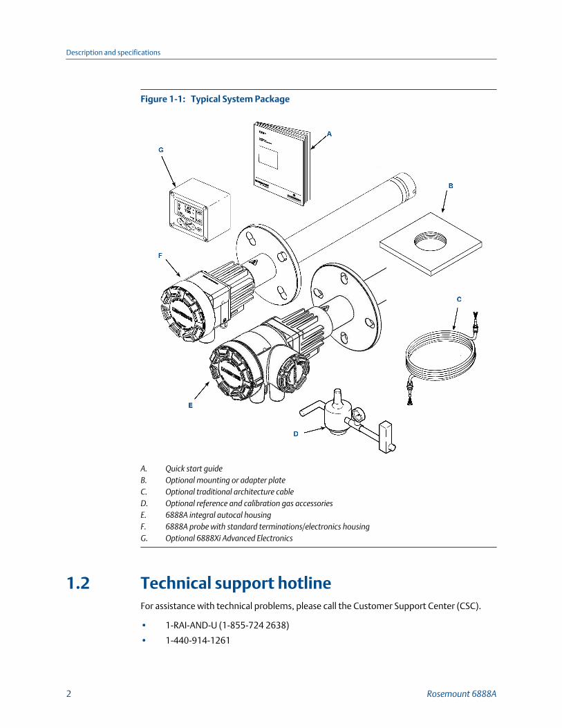
Typical System PackageFigure 1-1:
A. Quick start guideB. Optional mounting or adapter plateC. Optional traditional architecture cableD. Optional reference and calibration gas accessoriesE. 6888A integral autocal housingF. 6888A probe with standard terminations/electronics housingG. Optional 6888Xi Advanced Electronics
1.2 Technical support hotlineFor assistance with technical problems, please call the Customer Support Center (CSC).
• 1-RAI-AND-U (1-855-724 2638)
• 1-440-914-1261
Description and specifications
2 Rosemount 6888A
In addition to the CSC, you may also contact Field Watch. Field Watch coordinatesEmerson's field service throughout the US and abroad.
• 1-800-654-RSMT (1-800-654-7768)
Emerson may also be reached via the Internet through email and the World Wide Web.
• Email: [email protected]
• World Wide Web: www.Emerson.com/RosemountGasAnalysis
1.3 System overviewThe 6888 is Rosemount's latest combustion flue gas oxygen analyzer. This product isintended for measuring the flue gases resulting from any combustion process. It uses thesame heated sensing technology as the O2 sensors found in most automobiles. ContactRosemount's technical support group at 800-433-6076 for any applications other thanmeasuring combustion flue (exhaust) gases.
This product uses an in-situ sensor, i.e., the sensor is placed at the end of a probe, and theprobe extends directly into the flue gas duct or stack at a given length. The sensor is like athermocouple, generating its own millivolt signal based on the differences between areference gas (ambient or instrument air - always 20.95% O2) and the flue gases beingmeasured. There are several different arrangements of probes, electronics, and featuresthat are explained below and in the wiring diagrams.
An optional Rosemount 6888Xi with HART® communication provides a convenientoperator interface for setup, calibration, and diagnostics. HART communication is stillpresent when using the Rosemount 6888Xi.
1.4 System configurations
1.4.1 Transmitter probe, onlyThe Rosemount 6888 probe has the electronics in the blue housing that controls theheater temperature and also amplifies the raw O2 millivolt signal to a linear 4-20 mA. The4-20 mA signal lines can be run directly to the control room and also power the transmitterelectronics. As with most other Rosemount transmitters, measuring pressure,temperature, and flow setup is conducted through HART communications via a 475handheld communicator or via Asset Management Solutions (AMS).
1.4.2 Standard housing transmitter probe plus Rosemount6888Xi ElectronicsThe Rosemount 6888Xi Electronics serve as a local operator interface unit with a back-litdisplay and keypad. It is capable of two channels, serving two Rosemount 6888 probes.The Rosemount 6888Xi also carries these optional advanced features:
• Fully automatic calibration. Requires Xi O2 Cal Autocalibration system
Description and specifications
Reference Manual 3

• Loss of flame contact for powering down the heater in the event of a flame-outcondition in a furnace.
• Heaterless operation at process temperatures above 550 °C (1022 °F). This featurewill also permit operation above the heater setpoint of 736 °C (1357 °F). Sensing celllife will be shortened by operation above 800 °C (1472 °F), however.
• Plugged diffuser diagnostic operates by measuring the return-to-process rate aftercalibration gas has been stopped. This feature also includes auto gas switching whenthe reading settles out versus waiting for configured gas flow time to expire.
• Stochiometer - If a furnace goes into a reducing condition (zero % O2), this featurewill determine how far.
• Programmable reference - Permits more accurate readings at near-ambient O2levels (20.95% O2).
• A cal check capability. New calibration values are not automatically stored after acalibration. An accept/reject calibration feature can be enabled or disabled so thatthe techniciean or operator can decice to accept or reject a potentially large changein calibration values.
• Tolerance check that will alarm if the wrong test gases are being used or if a bottleruns out in the middle of a calibration. Take care to ensure gas 1 and gas 2calibration gases are properly configured if the tolerance check feature is enabled.
1.4.3 Transmitter probe and Rosemount 6888Xi with flamesafety interlockA flame safety interlock by Emerson is available for heater power disconnect wheneverthere is a loss of the process flame or a heater runaway condition (heater over-temperature) in the O2 probe. This input is internally powered by the Rosemount 6888Xiand is actuated via a dry contact output from your flame scanner. A closed contactindicates a flame is present. An open contact indicates a loss of flame. This feature is alsoavailable with the integral autocal housing.
1.4.4 Transmitter probe with integral autocal, Rosemount6888Xi, and HART® communicationsThis probe contains gas-switching solenoids so that the Rosemount 6888Xi electronics cancontrol the introduction of calibration gases. Calibrations can be initiated via a calibrationrecommended diagnostic, time since last calibration, manually via external dry contact,HART communications, or from the Rosemount 6888Xi local operator interface keypad.The integral autocal feature can only be implemented when the probe is used with aRosemount 6888Xi.
1.4.5 Transmitter probe with integral autocal andFOUNDATION™ Fieldbus (FF) communicationsThis probe contains gas-switching solenoids that can control the introduction ofcalibration gases for calibration. Calibrations can be initiated automatically via a calibrationrecommended diagnostic, time since last calibration, manually via the optional
Description and specifications
4 Rosemount 6888A
Rosemount 6888Xi keypad, FF communications via the 475 communicator, or AMSconsole. Unlike the HART transmitter electronics, the FF version can execute automaticcalibrations either with or without the optional Rosemount 6888Xi electronics. Likewise,advanced features can be implemented either with or without the optional Rosemount6888Xi.
1.4.6 Direct replacement (DR) probe with traditionalarchitecture Rosemount 6888Xi electronicsHere there are no electronics inside the probe head, so the raw sensor signals for theheater thermocouple and zironium oxide O2 sensor are sent to a remote Rosemount6888Xi Electronics. The Rosemount 6888 traditional architecture electronics will alsodirectly apply power to the probe heater in order to maintain the correct sensortemperature. This arrangement calls for a 7-conductor cable to carry this power and thesensor signals. Maximum length for the cable is 200 feet. This probe will also operate onprevious Westinghouse/Rosemount electronics (World Class and Oxymitter), as well asmany competitive electronics.
1.4.7 Wireless capabilityBoth the transmitter electronics in the head of the probe and the Rosemount 6888XiElectronics communicate over HART communications and can implement wirelesscommunications via Emerson Wireless 775 THUM™ Adapter.
1.4.8 Automatic calibrationCalibrations consist of introducting bottled gases of known value into the probe so thatthe electronics can make automatic adjustments to the O2 readings to match the bottledgas value.
Emerson recommends 0.4% O2 and 8% O2 (balance nitrogen) gases. Never use nitrogen orinstrument air as calibration gases. Flowmeters (for calibration gases) and regulators andflowmeters (for reference air) are available as loose components, mounted into anoptional manual calibration switching panel or a fully automatic calibration system(Figure 1-2) where calibration solenoids are switched from the Rosemount 6888XiAdvanced Electronics. See the Rosemount SPS 4001B Single Probe Autocalibration Sequenceror Rosemount IMPS 4000 Intelligent Multiprobe Test Gas Sequencer manuals for additionaldetails.
Description and specifications
Reference Manual 5

Rosemount 6888A with Rosemount 6888Xi Advanced Electronics andAutocalibration Sequencer
Figure 1-2:
A. Manual calibration switching panelB. Reference air setC. Rosemount SPS 4001B or Rosemount IMPS 4000D. Rosemount 6888Xi Advanced ElectronicsE. Rosemount 6888A O2 Transmitter
1.4.9 Communication optionsA customer-supplied 375/475 Field Communicator and/or the optional Rosemount 6888XiAdvanced Electronics accomplish Rosemount 6888A communications. Graphic displaysare available via the optional Rosemount OxyBalance Display and Averaging System.
Data communicationsYou can configure and diagnostically troubleshoot the Rosemount 6888A in one of twoways:
1. Using the optional Rosemount 6888Xi Advanced Electronics allows localcommunication with the electronics. The Rosemount 6888Xi also offers thefollowing optional advanced features:
• Fully automatic calibration.
• Optional flame safety interface (single probe version only).
• High temperature operation [above 700 °C (1292 °F) standard temperature].
• Stoichiometer feature provides the ability to indicate O2 efficiency when thecombustion process goes into reducing conditions (0% O2).
• Programmable reference provides enhanced accuracy when measuring at ornear O2 level (20.95% O2).
Description and specifications
6 Rosemount 6888A

• Plugged diffuser diagnostic to detect fouled diffuser.
2. Using the HART interface, the Rosemount's 6888A's 4-20 mA output line transmitsan analog signal proportional to the oxygen level. The HART output is superimposedon the 4-20 mA output line. This information can be accessed through the following:
• Rosemount 375/475 Field Communicator: The handheld communicator requiresdevice description (DD) software specific to the Rosemount 6888A. The DDsoftware is supplied with many 375/475 units, but can also be programmed intoexisting units at most Emerson service offices. See Chapter 3 for additionalinformation.
• Personal computer (PC): The use of a personal communicator requires AMSsoftware available from Emerson.
• Delta V and Ovation Distributed Control System (DCS) with AMS-insidecapability.
3. The Rosemount 6888A can also transmit HART information wirelessly via a wirelessTHUM Adapter. The THUM Adapter threads into the Rosemount 6888A conduit portand converts the 4-20 mA signal to a wireless protocol. All other HART information isalso transmitted.
In addition to the wireless THUM Adapter, a hard wire connection of the 4-20 mAsignal to the DCS may be used at the same time. More detailed informationregarding the application of the THUM Adapter is available in Product Data Sheet00813-0100-4075.
NoteThe 375 field communicator must be upgraded to System Software 2.0 with Graphic License foroperation with the Rosemount 6888A O2 transmitter. The AMS software must be upgraded to AMS8.0 or above.
Contact Emerson's Global Service Center (GSC) at 1-800-833-8314 to upgrade the 375 fieldcommunicator software to System Software 2.0 with Graphic License.
Optional Rosemount OxyBalance Display and AveragingSystem
The optional Rosemount OxyBalance Display and Averaging System receives up to eight4-20 mA signals from individual probes, trends individual outputs, and calculates fourprogrammable averages as additional 4-20 mA outputs. For more information, callRosemount at 1-800-433-6076.
Description and specifications
Reference Manual 7

Rosemount OxyBalance SystemFigure 1-3:
1.5 Probe options
1.5.1 Diffusion elementsThe Rosemount 6888A is available with one of three diffusion elements fitted to theprocess end. The basic diffusers provide for a constant outer probe tube diameter the fulllength of the probe. When the Rosemount 6888A is used with an abrasive shield, thediffuser body has a larger diameter with grooves to accept packing material to seal out flyash. The snubber and ceramic diffusers may also be fitted with a flash arrestor to reducethe possibility of the probe igniting from flammable gases within the process.
WARNING!
FLAME AND EXPLOSIONThe diffusers fitted with flash arrestors have been tested to provide a measure of protection inpreventing ignition of flammable gases. They are not intended to provide flame proof orexplosion proof protection for the Rosemount 6888A.
Description and specifications
8 Rosemount 6888A
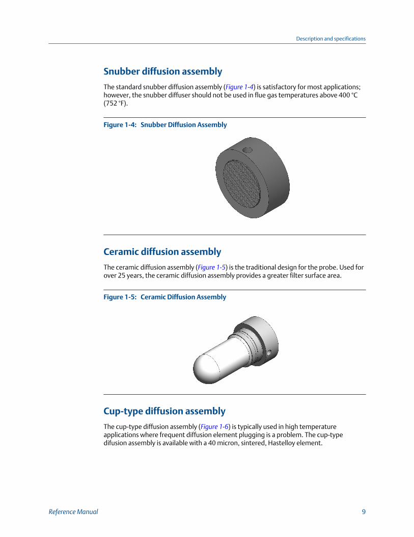
Snubber diffusion assembly
The standard snubber diffusion assembly (Figure 1-4) is satisfactory for most applications;however, the snubber diffuser should not be used in flue gas temperatures above 400 °C(752 °F).
Snubber Diffusion AssemblyFigure 1-4:
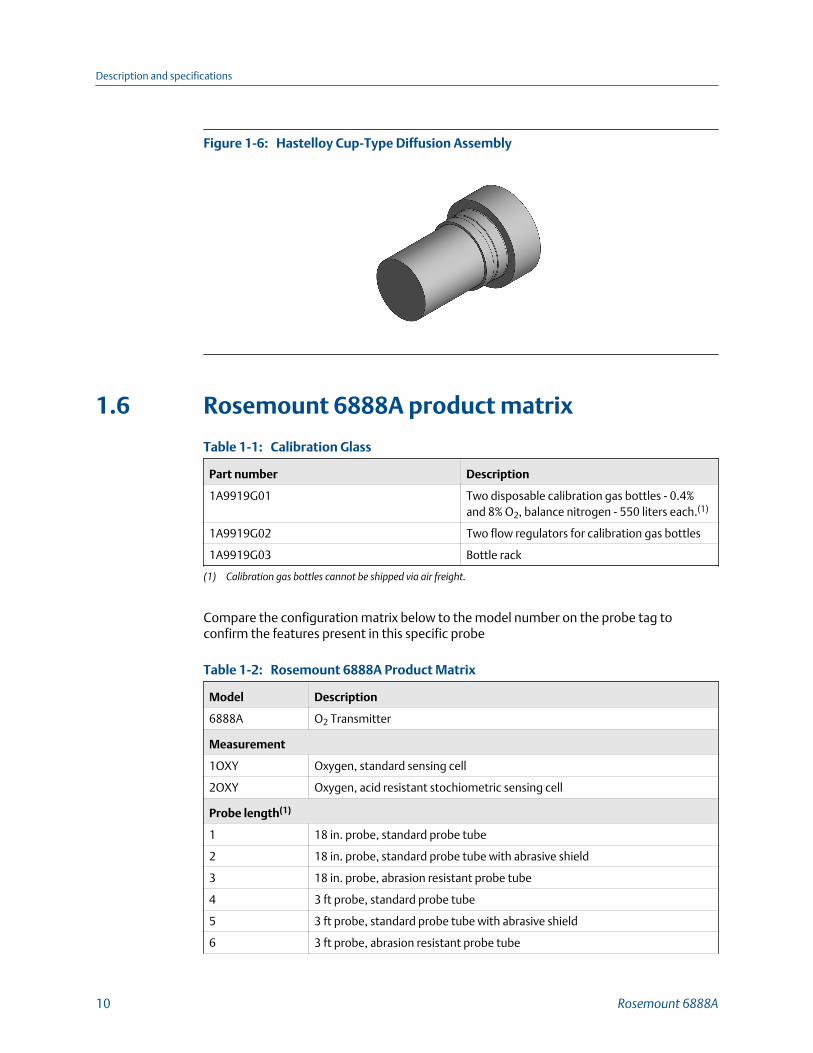
Ceramic diffusion assembly
The ceramic diffusion assembly (Figure 1-5) is the traditional design for the probe. Used forover 25 years, the ceramic diffusion assembly provides a greater filter surface area.
Ceramic Diffusion AssemblyFigure 1-5:
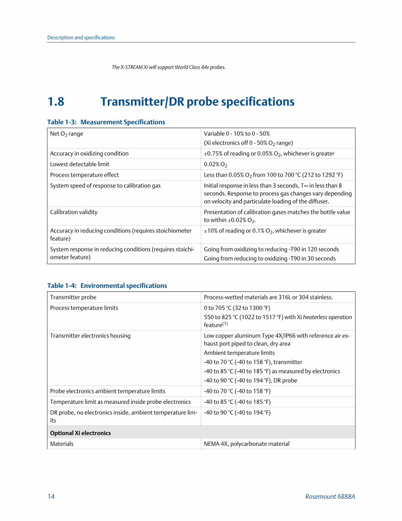
Cup-type diffusion assembly
The cup-type diffusion assembly (Figure 1-6) is typically used in high temperatureapplications where frequent diffusion element plugging is a problem. The cup-typedifusion assembly is available with a 40 micron, sintered, Hastelloy element.
Description and specifications
Reference Manual 9
Hastelloy Cup-Type Diffusion AssemblyFigure 1-6:
1.6 Rosemount 6888A product matrix
Calibration GlassTable 1-1:
Part number Description
1A9919G01 Two disposable calibration gas bottles - 0.4%and 8% O2, balance nitrogen - 550 liters each.(1)
1A9919G02 Two flow regulators for calibration gas bottles
1A9919G03 Bottle rack
(1) Calibration gas bottles cannot be shipped via air freight.
Compare the configuration matrix below to the model number on the probe tag toconfirm the features present in this specific probe
Rosemount 6888A Product MatrixTable 1-2:
Model Description
6888A O2 Transmitter
Measurement
1OXY Oxygen, standard sensing cell
2OXY Oxygen, acid resistant stochiometric sensing cell
Probe length(1)
1 18 in. probe, standard probe tube
2 18 in. probe, standard probe tube with abrasive shield
3 18 in. probe, abrasion resistant probe tube
4 3 ft probe, standard probe tube
5 3 ft probe, standard probe tube with abrasive shield
6 3 ft probe, abrasion resistant probe tube
Description and specifications
10 Rosemount 6888A

Rosemount 6888A Product Matrix (continued)Table 1-2:
7 6 ft probe, standard probe tube
8 6 ft probe, standard probe tube with abrasive shield
9 6 ft probe, abrasion resistant probe tube
A 9 ft probe, abrasion resistant probe tube
AA 9 ft probe, abrasion resistant probe tube with abrasive shield
B 12 ft probe, abrasion resistant probe tube
BA 12 ft probe, abrasion resistant probe tube with abrasive shield
Diffuser
1 Snubber 400 °C (752 °F)
1A Snubber with dust shield 400 °C (752 °F) (used with abrasive shield)
1F Snubber with flashback arrestor 400 °C (752 °F)
2 Ceramic 825 °C (1517 °F)
2A Ceramic with dust shield 825 °C (1517 °F) (used with abrasive shield)
2F Ceramic (825 °C) with flashback arrestor 825 °C (1517 °F)
3 Hastelloy 40 µm 705 °C (1292 °F)
3A Hastelloy with dust seal 40 µm 705 °C (1292 °F) *used with abrasive shield)
Housing and electronics
1HT Standard housing, transmitter electronics, HART communications
2HT Integral autocal, transmitter electronics, HART communications
4FF Integral autocal, transmitter electronics, Fieldbus communications
5DR Standard housing, direct replacement, no electronics
6DRY Standard housing, direct replacement, YEW electronics
Mounting plate
00 None
04 New installation - square weld plate with ANSI 2 in. - 150# studs & flange (2.5in. process hole required)
05 New installation - square weld plate with DIN studs and flange (2.5 in. processhole required)
06 New installation - variable insertion mount; abrasion resistant probe only
07 New installation - variable insertion mount; mounted to existing OXT/WCabrasive shield mounts; abrasion resistant probe only
08 Adapter to existing ANSI 3 in. 150# flange
09 Adapter to existing ANSI 4 in. 150# flange
10 Adapter to existing ANSI 6 in. 150# flange
11 Adapter to existing ANSI 3 in. 300# flange
12 Adapter to existing ANSI 4 in. 300# flange
Description and specifications
Reference Manual 11

Rosemount 6888A Product Matrix (continued)Table 1-2:
99 Special adapter - provide existing flange dimensions, including thru-hole di-ameter
Manual calibration accessories
00 None
01 Calibration and reference gas flowmeters and reference regulator/filter diffus-er
02 Calibration/reference panel
Stoichiometer function -FOUNDATION Fieldbus only (For HART versions, order this featurewith Rosemount 6888Xi Electronics)
0 No
1 Yes
Programmable reference function - FOUNDATION Fieldbus only (For HART versions, orderthis feature with Rosemount 6888Xi Electronics)
0 No
1 Yes
Extended temperature reference function - FOUNDATION Fieldbus only (For HART versions,order this feature with Rosemount 6888Xi Electronics)
0 No
1 Yes
Diffuser warning function - FOUNDATION Fieldbus only (For HART versions, order this featurewith Rosemount 6888Xi Electronics)
0 No
1 Yes
(1) Probes supplied with flanges with dual ANSI/DIN hole pattern.
1.7 Rosemount 6888Xi product matrixCompare the configuration matrix below to the model number on the probe tag toconfirm the features present in this specific probe.
Model Product description
6888Xi Advanced Electronics
Remote type
1OXY Single channel O2
2OXY Single channel O2 with flame safety interlock for heater
3OXY Dual channel O2
4OXY Single channel O2 with traditional architecture for 120 V probes(1)
Description and specifications
12 Rosemount 6888A

Mounting
00 No Hardware
01 Panel mount kit with gasket
02 2 in. pipe/wall mount kit
Cable
00 No cable
10 6 m (20 ft) cable, use with traditional architecture probe only
11 12 m (40 ft) cable, use with traditional architecture probe only
12 18 m (60 ft) cable, use with traditional architecture probe only
13 24 m (80 ft) cable, use with traditional architecture probe only
14 30 m (100 ft) cable, use with traditional architecture probe only
15 45 m (150 ft) cable, use with traditional architecture probe only
16 60 m (200 ft) cable, use with traditional architecture probe only
Stoichiometer function for O2
00 No
01 Single channel
02 Dual channel
Programmable reference function for O2
00 None
01 Single channel
02 Dual channel
Extended Temperature Function for O2
00 None
01 Single channel
02 Dual channel
Plugged diffuser diagnostics
00 None
01 Single channel
02 Dual channel
(1) The Rosemount 6888Xi does not support World Class 44v probes.
Description and specifications
Reference Manual 13
The X-STREAM Xi will support World Class 44v probes.
1.8 Transmitter/DR probe specifications
Measurement SpecificationsTable 1-3:
Net O2 range Variable 0 - 10% to 0 - 50%
(Xi electronics off 0 - 50% O2 range)
Accuracy in oxidizing condition ±0.75% of reading or 0.05% O2, whichever is greater
Lowest detectable limit 0.02% O2
Process temperature effect Less than 0.05% O2 from 100 to 700 °C (212 to 1292 °F)
System speed of response to calibration gas Initial response in less than 3 seconds, T∞ in less than 8seconds. Response to process gas changes vary dependingon velocity and particulate loading of the diffuser.
Calibration validity Presentation of calibration gases matches the bottle valueto within ±0.02% O2.
Accuracy in reducing conditions (requires stoichiometerfeature)
±10% of reading or 0.1% O2, whichever is greater
System response in reducing conditions (requires stoichi-ometer feature)
Going from oxidizing to reducing -T90 in 120 seconds
Going from reducing to oxidizing -T90 in 30 seconds
Environmental specificationsTable 1-4:
Transmitter probe Process-wetted materials are 316L or 304 stainless.
Process temperature limits 0 to 705 °C (32 to 1300 °F)
550 to 825 °C (1022 to 1517 °F) with Xi heaterless operationfeature(1)
Transmitter electronics housing Low copper aluminum Type 4X/IP66 with reference air ex-haust port piped to clean, dry area
Ambient temperature limits
-40 to 70 °C (-40 to 158 °F), transmitter
-40 to 85 °C (-40 to 185 °F) as measured by electronics
-40 to 90 °C (-40 to 194 °F), DR probe
Probe electronics ambient temperature limits -40 to 70 °C (-40 to 158 °F)
Temperature limit as measured inside probe electronics -40 to 85 °C (-40 to 185 °F)
DR probe, no electronics inside, ambient temperature lim-its
-40 to 90 °C (-40 to 194 °F)
Optional Xi electronics
Materials NEMA 4X, polycarbonate material
Description and specifications
14 Rosemount 6888A
Environmental specifications (continued)Table 1-4:
General purpose certifications
Xi ambient temperature limits -20 to 50 °C (-4 to 122 °F)
Xi temperature limits as measured inside the electronicshousing
-20 to 70 °C (-4 to 158 °F)
(1) Reduced cell life can be expected if operated continously at temperatures above 705 °C (1300 °F). Optional bypass and jacketaccessories permit operation to 1050 °C (1922 °F).
Installation specifications - probeTable 1-5:
Probe mounting flange Vertical or horizontal - 2 in. 150# (121 m (4.75 in.) bolt cir-cle)
NoteFlanges are flat-faced and for mounting only. Flanges arenot pressure-rated. A 2.5-in. diameter hole in the processis required.
Spool piece PN 3D39761G02 is available to offset probeelectronics housing from hot duct work.
Many adapter flanges are available to mate to existingflanges.
Probe lengths and approximate shipping weights
457 mm (18 in.) package 7.3 kg (16 lb)
0.91 m (3 ft) package 9.5 kg (21 lb)
1.83 m (6 ft) package 12.2 kg (27 lb)
2.74 m (9 ft) package 15.0 kg (33 lb)
3.66 m (12 ft) package 17.7 kg (39 lb)
Reference air (optional) 2 scfh (1 L/min), clean, dry, instrument-quality air (20.95%O2), regulated to 5 psi (34 kPa)
Calibration Semi-automatic or automatic
Calibration gases 0.4% O2 and 8% O2, balance N2recommended. Instrumentair may be used as a high cal gas but is not recommended.
100% nitrogen cannot be used as the low cal gas.
Calibration gas line 91 m (300 ft) maximum length
Calibration gas flow 5 scfh (2.5 L/min)
Heater electrical power 120/140 Vac ± 10%, 50/60 Hz, 260/1020 VA max, 1/2-in. -14 NPT conduit ports
Traditional architecture cable 61 m (200 ft) maximum length
Power consumption of probe heater 776 VA maximum during warm-up
Description and specifications
Reference Manual 15
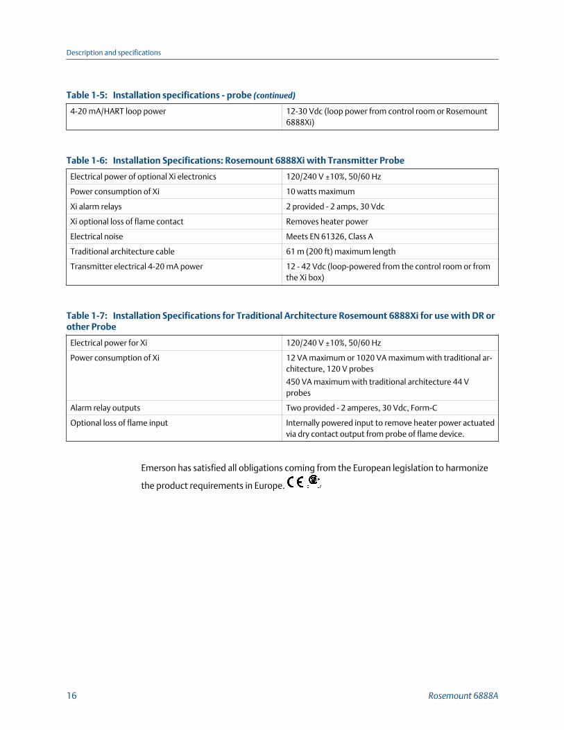
Installation specifications - probe (continued)Table 1-5:
4-20 mA/HART loop power 12-30 Vdc (loop power from control room or Rosemount6888Xi)
Installation Specifications: Rosemount 6888Xi with Transmitter ProbeTable 1-6:
Electrical power of optional Xi electronics 120/240 V ±10%, 50/60 Hz
Power consumption of Xi 10 watts maximum
Xi alarm relays 2 provided - 2 amps, 30 Vdc
Xi optional loss of flame contact Removes heater power
Electrical noise Meets EN 61326, Class A
Traditional architecture cable 61 m (200 ft) maximum length
Transmitter electrical 4-20 mA power 12 - 42 Vdc (loop-powered from the control room or fromthe Xi box)
Installation Specifications for Traditional Architecture Rosemount 6888Xi for use with DR orother ProbeTable 1-7:
Electrical power for Xi 120/240 V ±10%, 50/60 Hz
Power consumption of Xi 12 VA maximum or 1020 VA maximum with traditional ar-chitecture, 120 V probes
450 VA maximum with traditional architecture 44 Vprobes
Alarm relay outputs Two provided - 2 amperes, 30 Vdc, Form-C
Optional loss of flame input Internally powered input to remove heater power actuatedvia dry contact output from probe of flame device.
Emerson has satisfied all obligations coming from the European legislation to harmonize
the product requirements in Europe.
Description and specifications
16 Rosemount 6888A
2 Install
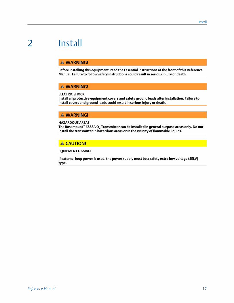
WARNING!
Before installing this equipment, read the Essential Instructions at the front of this ReferenceManual. Failure to follow safety instructions could result in serious injury or death.
WARNING!
ELECTRIC SHOCKInstall all protective equipment covers and safety ground leads after installation. Failure toinstall covers and ground leads could result in serious injury or death.
WARNING!
HAZARDOUS AREASThe Rosemount™ 6888A O2 Transmitter can be installed in general purpose areas only. Do notinstall the transmitter in hazardous areas or in the vicinity of flammable liquids.
CAUTION!
EQUIPMENT DAMAGE
If external loop power is used, the power supply must be a safety extra low voltage (SELV)type.
Install
Reference Manual 17

2.1 System considerations
NOTICE
Plug all unused ports on the Rosemount 6888A probe housing with suitable fittings.
A typical system installation for a Rosemount 6888A with integral electronics is shown in Figure 2-1.
Typical system installationFigure 2-1:
A. GasesB. DuctC. Adapter plate and flangeD. Instrument air supply (reference air)E. Pressure regulatorF. FlowmeterG. Calibration gasH. Line voltageI. 4 to 20 mA signalJ. Rosemount 6888Xi Advanced Electronics (optional)K. Stack
A source of instrument air is required at the transmitter for reference air flow [2.0 scfh(1.0 L/min)]. Since the unit is equipped with an in place calibration feature, you can makeprovisions to permanently connect calibration gas bottles to the transmitter.
Install
18 Rosemount 6888A

If the calibration gas bottles will be permanently connected, install a check valve next tothe calibration fittings on the probe. This check valve is to prevent breathing of thecalibration gas line and subsequent flue gas condensation and corrosion. The check valveis in addition to the stop valve on the calibration gas bottles or the solenoid valves in theRosemount SPS 40001B or Rosemount IMPS 4000.
If the Rosemount 6888Xi Advanced Electronics option is not used, the 4 to 20 mA signalfrom the probe will be loop-powered from the DCS. A 375/475 Field Communicator orAMS is required to set up and operate the probe.
The optional Rosemount 6888Xi enhanced interface communicates with the probetransmitter electronics via HART® communications riding on to the 4 to 20 mA signalcoming from the transmitter. If using the 375/475 Field Communicator, connect it to the 4to 20 mA signal loop between the Rosemount 6888Xi and the control room or dataacquisition system. Connecting the 375/475 Field Communicator between the transmitterand Rosemount 6888Xi will cause communication errors and affect system operation.
NOTICE
The transmitter electronics is rated Type 4X and IP66 and is capable of operation attemperatures from -40 to 85 °C (-40 to 185 °F). Retain the packaging in which the Rosemount6888A arrived from the factory in case any components are to be shipped to another site. Thispackaging has been designed to protect the product.
2.2 Mechanical installationMost combustion processes run only slightly negative or positive in pressure, so that theprobe flange is for mechanical mounting only. The probe is not rated for high pressures. Ifthis is a new installation, a weld plate for welding to the flue gas duct can be supplied.
WARNING!
ELECTRIC SHOCKInstall all protective equipment covers and safety ground leads after installation. Failure toinstall covers and ground leads could result in serious injury or death. The Rosemount 6888AO2 transmitter can be installed in general purpose areas only. Do not install the transmitter orthe Rosemount 6888Xi in hazardous areas or in the vicinity of flammable liquids.
Install
Reference Manual 19

2.2.1 Install probeComplete the following steps to install the Rosemount 6888A O2 probe.
1. Ensure all components are available to install the Rosemount 6888A O2 probe.
Refer to the probe installation details in Figure 2-1. If using the optional ceramic orHastelloy diffusion element, the vee deflector must be correctly oriented.
2. Before inserting the Rosemount 6888A probe, check the direction of gas flow in theduct. Orient the vee deflector so the apex points upstream toward the flow. See Figure 2-2.
Orienting the Optional Vee DeflectorFigure 2-2:
A. Gas flow directionB. Vee deflectorC. Diffusion elementD. SetscrewE. Vee deflectorF. FilterG. Apex
3. If using the standard square weld plate or an optional flange mounting plate, weld orbolt the plate onto the duct.
Install
20 Rosemount 6888A
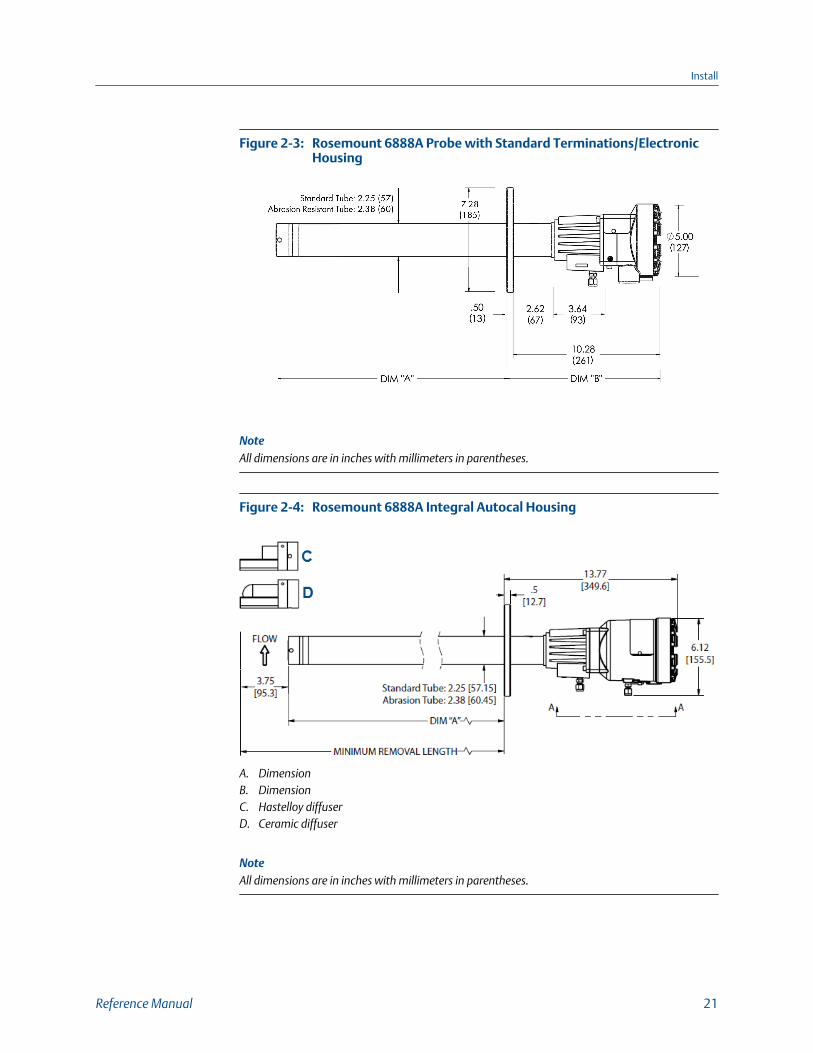
Rosemount 6888A Probe with Standard Terminations/ElectronicHousing
Figure 2-3:
NoteAll dimensions are in inches with millimeters in parentheses.
Rosemount 6888A Integral Autocal HousingFigure 2-4:
A. DimensionB. DimensionC. Hastelloy diffuserD. Ceramic diffuser
NoteAll dimensions are in inches with millimeters in parentheses.
Install
Reference Manual 21

Rosemount 6888A Integral Autocal Housing Close-upFigure 2-5:
A. DimensionB. DimensionC. Calibration gas 1/4 tube fittings 5.0 SCFH (2.4 L/min) 20 PSI (138 kPa)D. #10 socket head cap screw (external ground)E. 1/2 NPT conduit connection (power, signal)F. Reference gas 1/4 tube fitting 2.0 SCFH (1.0 L/min) 20 PSI (138 kPa)G. Reference air vents
NoteAll dimensions are in inches with millimeters in parentheses.
Removal/InstallationTable 2-1:
Probe length(1) Dim A insertion depthDim B removal envelopestandard housing
Dim B removal envelopeaccessory housing
457 mm (18 in.) probe 409 mm (16.1in.) 401 mm (15.77 in.) 490 mm (19.26 in.)
0.91 m (3 ft) probe 826 mm (33.52 in.) 1182 mm (46.6 in.) 1271 mm (50.1 in.)
1.83 m (6 ft) probe 1740 mm (68.52 in.) 2097 mm (82.6 in.) 2186 mm (86.1 in.)
2.74 m (9 ft) probe 2655 mm (104.52 in.) 3011 mm (118.6 in.) 3100 mm (122.1 in.)
3.66 m (12 ft) probe 3569 mm (140.52 in.) 3926 mm (154.6 in.) 4015 mm (158.1 in.)
(1) Add 96 mm (3.8 in.) to Dim A and Dim B for probe with ceramic or Hastelloy diffuser.
The through hole diameter in the stack or duct wall and refractory material must beat least 63.5 mm (2-1/2 in.)
4. Insert probe through the opening in the mounting flange and bolt the unit to theflange.
Install
22 Rosemount 6888A
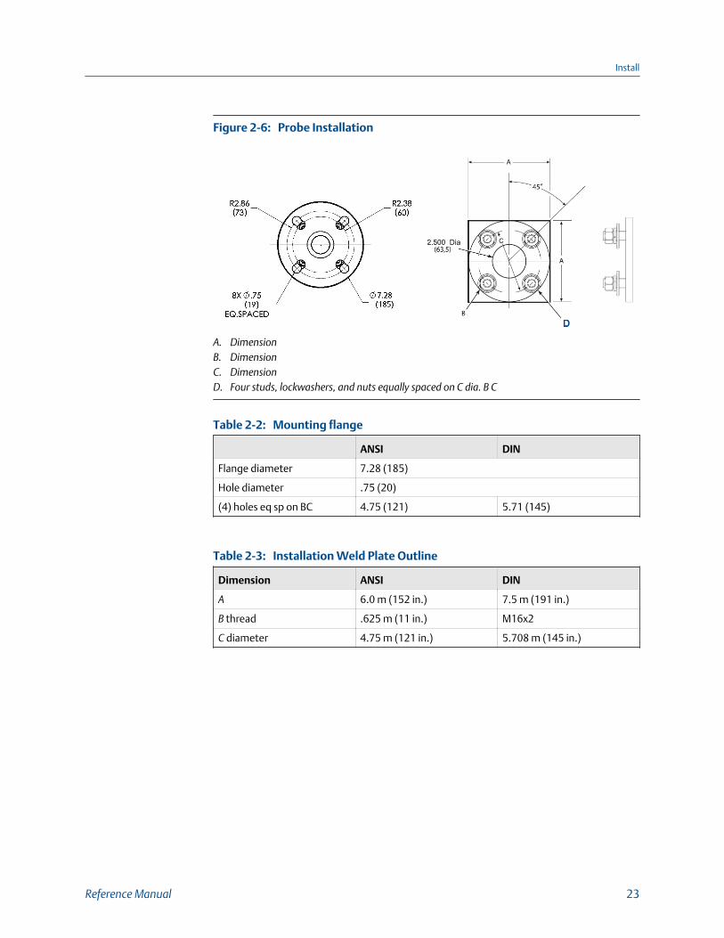
Probe InstallationFigure 2-6:
A. DimensionB. DimensionC. DimensionD. Four studs, lockwashers, and nuts equally spaced on C dia. B C
Mounting flangeTable 2-2:
ANSI DIN
Flange diameter 7.28 (185)
Hole diameter .75 (20)
(4) holes eq sp on BC 4.75 (121) 5.71 (145)
Installation Weld Plate OutlineTable 2-3:
Dimension ANSI DIN
A 6.0 m (152 in.) 7.5 m (191 in.)
B thread .625 m (11 in.) M16x2
C diameter 4.75 m (121 in.) 5.708 m (145 in.)
Install
Reference Manual 23
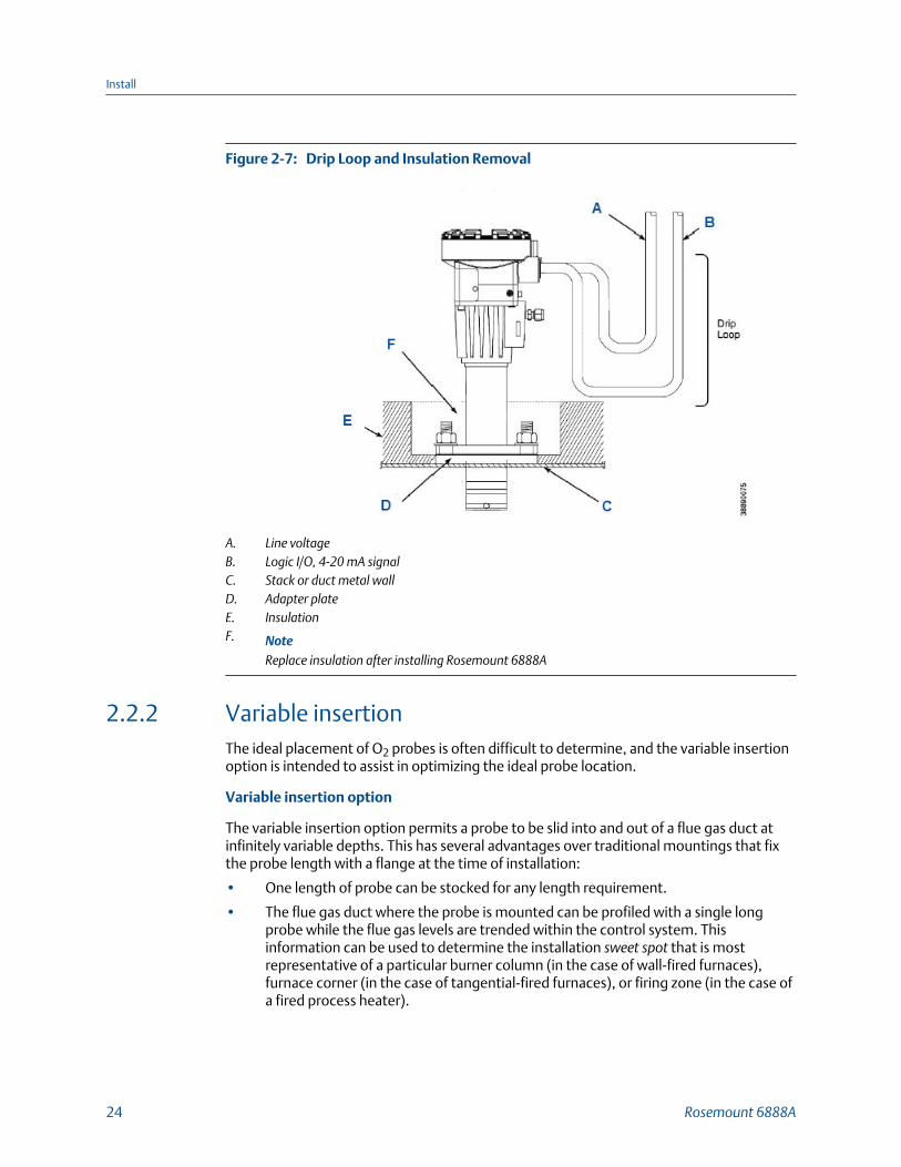
Drip Loop and Insulation RemovalFigure 2-7:
A. Line voltageB. Logic I/O, 4-20 mA signalC. Stack or duct metal wallD. Adapter plateE. InsulationF. Note
Replace insulation after installing Rosemount 6888A
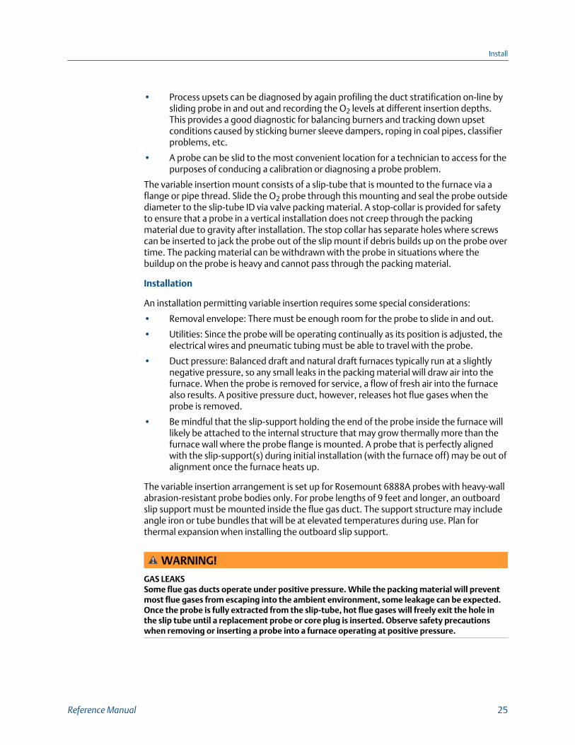
2.2.2 Variable insertionThe ideal placement of O2 probes is often difficult to determine, and the variable insertionoption is intended to assist in optimizing the ideal probe location.
Variable insertion option
The variable insertion option permits a probe to be slid into and out of a flue gas duct atinfinitely variable depths. This has several advantages over traditional mountings that fixthe probe length with a flange at the time of installation:
• One length of probe can be stocked for any length requirement.
• The flue gas duct where the probe is mounted can be profiled with a single longprobe while the flue gas levels are trended within the control system. Thisinformation can be used to determine the installation sweet spot that is mostrepresentative of a particular burner column (in the case of wall-fired furnaces),furnace corner (in the case of tangential-fired furnaces), or firing zone (in the case ofa fired process heater).
Install
24 Rosemount 6888A
• Process upsets can be diagnosed by again profiling the duct stratification on-line bysliding probe in and out and recording the O2 levels at different insertion depths.This provides a good diagnostic for balancing burners and tracking down upsetconditions caused by sticking burner sleeve dampers, roping in coal pipes, classifierproblems, etc.
• A probe can be slid to the most convenient location for a technician to access for thepurposes of conducing a calibration or diagnosing a probe problem.
The variable insertion mount consists of a slip-tube that is mounted to the furnace via aflange or pipe thread. Slide the O2 probe through this mounting and seal the probe outsidediameter to the slip-tube ID via valve packing material. A stop-collar is provided for safetyto ensure that a probe in a vertical installation does not creep through the packingmaterial due to gravity after installation. The stop collar has separate holes where screwscan be inserted to jack the probe out of the slip mount if debris builds up on the probe overtime. The packing material can be withdrawn with the probe in situations where thebuildup on the probe is heavy and cannot pass through the packing material.
Installation
An installation permitting variable insertion requires some special considerations:
• Removal envelope: There must be enough room for the probe to slide in and out.
• Utilities: Since the probe will be operating continually as its position is adjusted, theelectrical wires and pneumatic tubing must be able to travel with the probe.
• Duct pressure: Balanced draft and natural draft furnaces typically run at a slightlynegative pressure, so any small leaks in the packing material will draw air into thefurnace. When the probe is removed for service, a flow of fresh air into the furnacealso results. A positive pressure duct, however, releases hot flue gases when theprobe is removed.
• Be mindful that the slip-support holding the end of the probe inside the furnace willlikely be attached to the internal structure that may grow thermally more than thefurnace wall where the probe flange is mounted. A probe that is perfectly alignedwith the slip-support(s) during initial installation (with the furnace off) may be out ofalignment once the furnace heats up.
The variable insertion arrangement is set up for Rosemount 6888A probes with heavy-wallabrasion-resistant probe bodies only. For probe lengths of 9 feet and longer, an outboardslip support must be mounted inside the flue gas duct. The support structure may includeangle iron or tube bundles that will be at elevated temperatures during use. Plan forthermal expansion when installing the outboard slip support.
WARNING!
GAS LEAKSSome flue gas ducts operate under positive pressure. While the packing material will preventmost flue gases from escaping into the ambient environment, some leakage can be expected.Once the probe is fully extracted from the slip-tube, hot flue gases will freely exit the hole inthe slip tube until a replacement probe or core plug is inserted. Observe safety precautionswhen removing or inserting a probe into a furnace operating at positive pressure.
Install
Reference Manual 25

CAUTION!
This variable insertion mount is intended for use in negative pressure ducts and postivepressure ducts where the flue gas pressure is no more than 1 psi. Emerson offers other systemswith isolation valve and pressure balancing for applications where the pressure is up to 50 psi.
2.3 Electrical installationAll wiring must conform to local and national codes. Multiple wiring diagrams are shown inthis section. Always refer to the diagrams that apply to your transmitter configuration anddisregard all other wiring diagrams.
WARNING!
ELECTRIC SHOCKDisconnect and lock out power before connecting the power supply.
Install all protective covers and safety ground leads after installation. Failure to install coversand ground leads could result in serious injury or death.
To meet the safety requirements of IEC 61010-1 (EC requirement) and ensure safe operation ofthis equipment, connect the main electrical power supply through a circuit breaker (min 10 A)which will disconnect all current-carrying conductors during a fault situation. This circuitbreaker should also include a mechanically operated isolating switch. If not, keep anotherexternal means of disconnecting the supply from the equipment located close by. Circuitbreakers or switches must comply with a recognized standard such as IEC 947.
NOTICE
To maintain proper earth grounding, ensure a positive connection exists between thetransmitter housing and earth. The connecting ground wire must be 14 AWG minimum.
NOTICE
Line voltage, signal, and relay wiring should be rated for at least 105 °C (221 °F).
2.3.1 Wiring for Rosemount 6888 Transmitter probe only (noRosemount 6888Xi Electronics)The Rosemount 6888 transmitter probe has electronics in the blue housing that controlsthe heater temperature and also amplifies the raw O2 millivolt signal to a linear 4-20 mA.The 4-20 mA signal lines can be run directly to the control room and also power thetransmitter electronics. There is no O2 display or keypad on the probe, so you must set upthrough HART® communications via a 475 handheld communicator or via AssetManagement Solutions (AMS).
1. Remove the cover from the probe.
2. Connect the line (L1 wire) to the L1 terminal, the netural (L2 wire) to the L2/Nterminal, and the ground wire to the ground lug.
Install
26 Rosemount 6888A

The transmitter accepts 120/240 Vac ±10% line voltage and 50/60 Hz. No setup isrequired.
Rosemount 6888A Standard Probe HousingFigure 2-8:
3. Connect the 4-20 mA signal wires at the transmitter. Use a shielded twisted wirepair.
Do not allow bare shield wires to contact the circuit boards. Insulate the shield wiresprior to termination. The transmitter electronics are loop-powered, i.e., the 4-20 mAsignal wires supply 24 Vdc from the DCS or an external power supply.
4. Terminate the shield only at the transmitter electronics housing unless using aRosemount 6888Xi. When using the Rosemount 6888Xi Advanced Electronics,terminate the shield at both ends.
NOTICEThe 4-20 mA signal represents the O2 value and also powers the probe-mountedelectronics. Superimposed on the 4-20 mA signal is HART information accessiblethrough a Field Communicator or AMS software.
5. Reinstall cover on transmitter.
6. Follow the remaining electrical instructions only if the Rosemount 6888Xi isincluded with your system configuration.
Install
Reference Manual 27

2.3.2 Standard housing transmitter probe plus Rosemount6888Xi ElectronicsThe Rosemount 6888Xi Electronics serve as an operator interface unit with a back-litdisplay and keypad. It is capable of two channels, serving two Rosemount 6888 probes.
1. Remove cover screws from the front cover of the Rosemount 6888Xi. Swing downthe front cover of the interface box.
2. Pull out the I/O board on the right side of the card rack inside the Rosemount6888Xi.
If your system is configured to operate two transmitter probes, there are two I/Ointerface boards. See Figure 2-9.
Install
28 Rosemount 6888A

Wiring Diagrams - Single/Dual Channel Wiring DiagramFigure 2-9:
NoteA. Except for JP5, JP2, and JP8 on IO board, jumper and switch settings are factory set and are
shown for reference only.B. IO board 4-20 mA/HART loop power settings:
JP5: Pins 1-2 internal power Rosemount 6888Xi to Rosemount 6888 transmitter, pins 2-3external power Rosemount 6888Xi to Rosemount 6888 transmitter (requires 2500 resistoracross J4, PR+ to PR-)
JP7/JP8: Pins 1-2 internal power Rosemount 6888Xi to DCS, pins 2-3 external power Rosemount6888Xi to DCS.
Compare the configuration matrix below to the model number on the probe tag toconfirm the features present in this specific probe.
Remote TypeTable 2-4:
1OXY Single channel O2
2OXY Single channel O2 with flame safety interlocking heater
3OXY Dual channel O2
Install
Reference Manual 29

Remote Type (continued)Table 2-4:
4OXY Single channel O2 traditional architecture for 120 V probes
Install
30 Rosemount 6888A

Rosemount 6888Xi Front and Bottom ViewFigure 2-10:
A. Power supply boardB. Channel #2 IO boardC. Shield groundD. Channel #1 IO boardE. AC input to P/SF. PlugG. Channel #2 alarm relay, SPS/IMPSH. Channel #2 4-20 mA/HART outputI. Channel #1 alarm relay SPS/IMPSJ. Channel #1 4-20 mA/HART output
Install
Reference Manual 31
3. Connect the 4-20 mA signal wires at J4 of the I/O board. Attach the supplied ferriteclamp over the 4-20 mA out wires that extend past the shield.
NOTICEInstallation of the ferrite clamp over the 4-20 mA out wires is required for thecompliance with the European EMC directive.
4. Terminate the shield of the 4-20 mA signal wires at the designated ground terminalof the Rosemount 6888Xi. Do not allow bare shield wires to contact the circuitboards. Insulate the shield wires prior to termination.
5. Connect the signal wires from the Rosemount SPS or Rosemount IMPS (if used) tothe applicable terminals of J3. Refer to the Rosemount SPS 4001B or Rosemount IMPS 4000 instruction manual for wiring details.
6. Reinstall the I/O board in the card rack of the Rosemount 6888Xi.
7. If your system is configured or two channel operation, repeat steps 2 through 7 toconnect the other probe's signal wires.
8. Remove the probe's connector from the power supply board located on the left sideof the card rack inside the Rosemount 6888Xi.
9. Connect the line, or L1, wire to the L1 terminal and the neutral, or L2, wire to the Nterminal.
10. Reinstall the power supply connector in the power supply board.
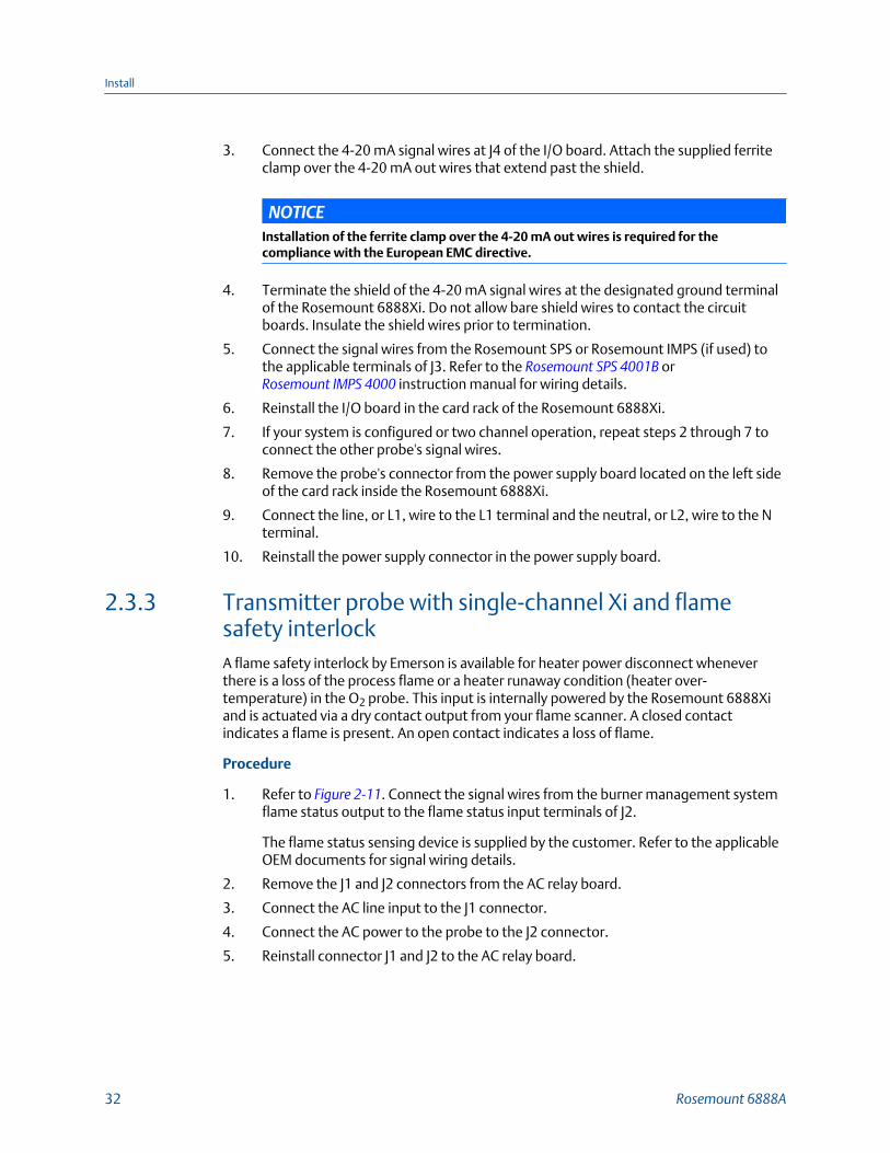
2.3.3 Transmitter probe with single-channel Xi and flamesafety interlockA flame safety interlock by Emerson is available for heater power disconnect wheneverthere is a loss of the process flame or a heater runaway condition (heater over-temperature) in the O2 probe. This input is internally powered by the Rosemount 6888Xiand is actuated via a dry contact output from your flame scanner. A closed contactindicates a flame is present. An open contact indicates a loss of flame.
Procedure
1. Refer to Figure 2-11. Connect the signal wires from the burner management systemflame status output to the flame status input terminals of J2.
The flame status sensing device is supplied by the customer. Refer to the applicableOEM documents for signal wiring details.
2. Remove the J1 and J2 connectors from the AC relay board.
3. Connect the AC line input to the J1 connector.
4. Connect the AC power to the probe to the J2 connector.
5. Reinstall connector J1 and J2 to the AC relay board.
Install
32 Rosemount 6888A
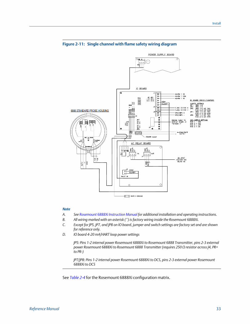
Single channel with flame safety wiring diagramFigure 2-11:
NoteA. See Rosemount 6888Xi Instruction Manual for additional installation and operating instructions.B. All wiring marked with an asterisk (*) is factory wiring inside the Rosemount 6888Xi.C. Except for JP5, JP7, and JP8 on IO board, jumper and switch settings are factory set and are shown
for reference only.D. IO board 4-20 mA/HART loop power settings
JP5: Pins 1-2 internal power Rosemount 6888Xi to Rosemount 6888 Transmitter, pins 2-3 externalpower Rosemount 6888Xi to Rosemount 6888 Transmitter (requires 250 Ω resistor across J4, PR+to PR-)
JP7/JP8: Pins 1-2 internal power Rosemount 6888Xi to DCS, pins 2-3 external power Rosemount6888Xi to DCS
See Table 2-4 for the Rosemount 6888Xi configuration matrix.
Install
Reference Manual 33
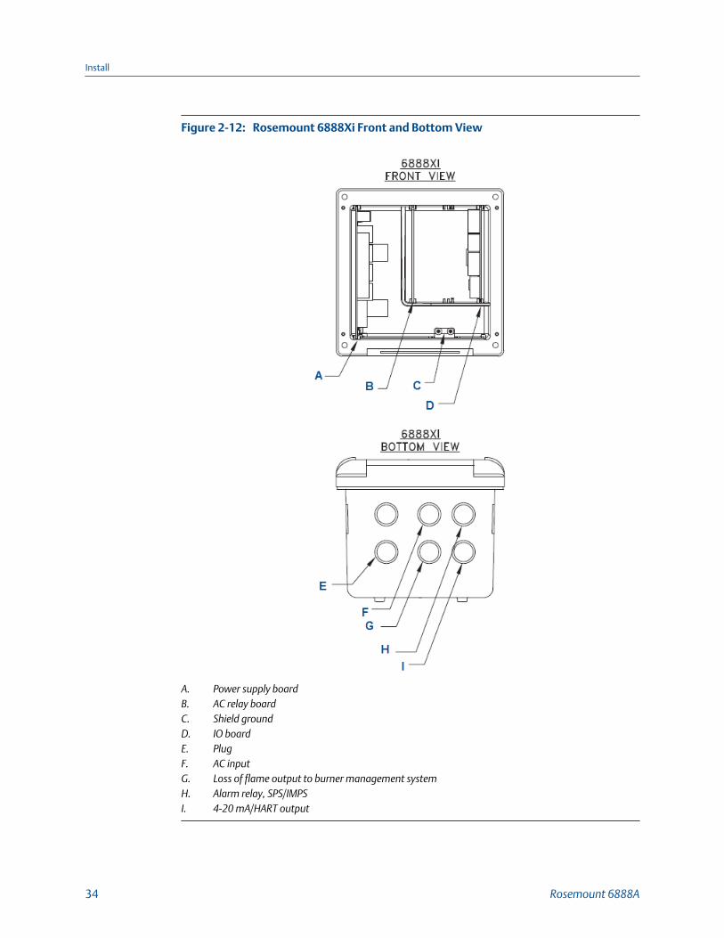
Rosemount 6888Xi Front and Bottom ViewFigure 2-12:
A. Power supply boardB. AC relay boardC. Shield groundD. IO boardE. PlugF. AC inputG. Loss of flame output to burner management systemH. Alarm relay, SPS/IMPSI. 4-20 mA/HART output
Install
34 Rosemount 6888A
2.3.4 Transmitter probe with integral autocal and HARTcommunicationsThis probe contains gas-switching solenoids so that the Rosemount 6888Xi Electronics cancontrol the introduction of calibration gases. Calibrations can be initiated via a calibrationrecommended diagnostic, time since last calibration, manually via external dry contact,HART communications, or from the Rosemount 6888Xi local operator interface keypad.The integral autocal feature can only be implemented when the probe is used with aRosemount 6888Xi.
1. Remove the two covers from the transmitter.
2. Connect the line (L1 wire) to the L1 terminal, the neutral (L2) wire to the L2/Nterminal, and the ground wire to the ground lug.
The Rosemount 6888A accepts 120/240 Vac ±10%, 50/60 Hz. No setup is required.
3. Connect the 4-20 mA signal wires form the Rosemount 6888Xi to the connections inthe side chamber of the transmitter.
Do not connect the signal wires to the terminals in the main chamber where the ACinput wires are connected. Use a shielded twisted wire pair. Do not allow bare shieldwires to contact the circuit boards. Insulate the shield wires prior to termination. The24 Vdc loop power is sourced from the Rosemount 6888Xi.
4. Terminate the shield at both the probe and the Rosemount 6888Xi AdvancedElectronics.
NOTICEThe 4-20 mA signal represents the O2 value and also powers the probe-mountedelectronics. Superimposed on the 4-20 mA signal is HART information accessiblethrough a field communicator or AMS software.
5. Reinstall both covers on transmitter.
6. Follow the remaining electrical installation instructions for the Rosemount 6888Xiincluded with your system configuration.
See Table 2-4 for the Rosemount 6888Xi product matrix.
Install
Reference Manual 35
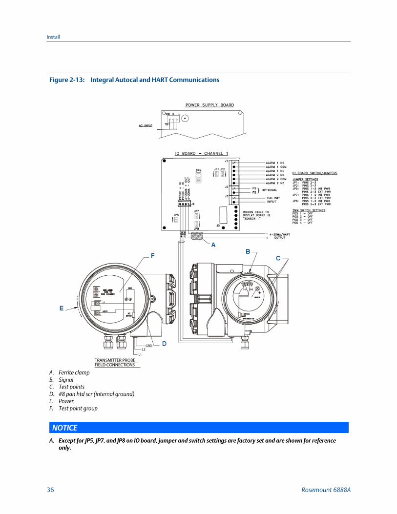
Integral Autocal and HART CommunicationsFigure 2-13:
A. Ferrite clampB. SignalC. Test pointsD. #8 pan htd scr (internal ground)E. PowerF. Test point group
NOTICE
A. Except for JP5, JP7, and JP8 on IO board, jumper and switch settings are factory set and are shown for referenceonly.
Install
36 Rosemount 6888A

B. IO board: 4-20 mA/HART loop power settings• JP5
• Pins 1-2: internal power Rosemount 6888 Xi to Rosemount 6888 transmitter• Pins 2-5: external power Rosemount 6888 Xi to Rosemount 6888 transmitter (requires 2,500 resistor across
J4, PR+ to PR-)• JP7/JP8
• Pins 1-2: internal power to DCS• Pins 2-3: external power Rosemount 6888 Xi to DCS
NOTICE
I/O board - Channel 2 is a duplicate of Channel 1.
See Figure 2-10 for the front and bottom view of the Rosemount 6888Xi.
2.3.5 Wire the Rosemount 6888A Transmitter probe withintegral autocal and FOUNDATION™ FieldbuscommunicationsThis probe contains gas-switching solenoids so that the Rosemount 6888Xi electronics cancontrol the introduction of calibration gases. Calibrations can be initiated manually via acalibration recommended diagnostic, time since last calibration, manually via external drycontact, HART communications, or from the Rosemount 6888Xi local operator interfacekeypad. The integral autocal feature can only be implemented when the probe is used witha Rosemount 6888Xi.
1. Remove the two covers from the transmitter.
2. Connect the line (L1) wire to the L1 terminal, the neutral (L2) wire to the L2/Nterminal, and the ground wire to the ground lug.
The Rosemount 6888A accepts 120/240 Vac ±10% line voltage and 50/60 Hz. Nosetup is required.
3. Connect the FOUNDATION Fieldbus wires from the Rosemount 6888 side housing tothe FF segment.
The Rosemount 6888 probe is not rated as intrinsically safe and will render any IS orFISCO segment it is wired to as non-IS. Use a shielded twisted wire pair. Do not allowbare shield wires to contact the circuit boards.
4. Terminate the shield at both the probe and the Rosemount 6888Xi advancedelectronics.
NOTICEThe FOUNDATION Fieldbus signal represents the O2 value and also powers the probe-mounted electronics.
Install
Reference Manual 37
5. Reinstall both covers on transmitter.
6. Follow the remaining electrical installation instructions for the Rosemount 6888Xiincluded with your system configuration.
2.3.6 Wire the traditional architecture system with directreplacement probe (no electronics inside)Here there are no electronics inside the probe head, so the raw sensor signals for theheater thermocouple and zirconium oxide (O2) sensor are sent to a remote Rosemount6888Xi electronics. The Rosemount 6888Xi electronics also directly applies power to theprobe heater in order to maintain the correct sensor temperature. This arrangement callsfor a 7-conductor cable to carry this power and the sensor signals. Maximum length for thiscable is 200 feet.
1. Remove cover from probe.
2. Feed all DR probe wiring through line power conduit of probe.
3. Connect DR probe heater power leads to DR probe connectors, Figure 2-14.
See Table 2-4 for the Rosemount 6888Xi product matrix.
Install
38 Rosemount 6888A
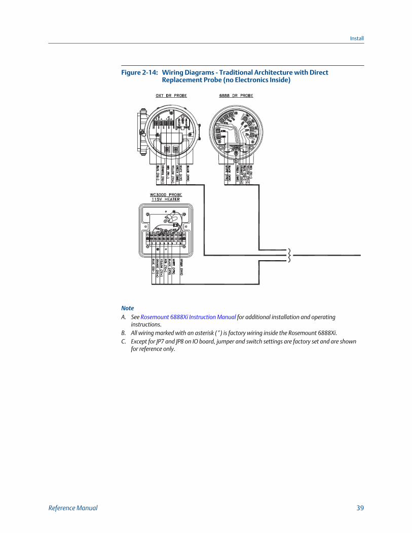
Wiring Diagrams - Traditional Architecture with DirectReplacement Probe (no Electronics Inside)
Figure 2-14:
NoteA. See Rosemount 6888Xi Instruction Manual for additional installation and operating
instructions.B. All wiring marked with an asterisk (*) is factory wiring inside the Rosemount 6888Xi.C. Except for JP7 and JP8 on IO board, jumper and switch settings are factory set and are shown
for reference only.
Install
Reference Manual 39

A. Power supply boardB. DR boardC. Shield groundD. IO boardE. PlugF. Probe cableG. AC inputH. Alarm relay SPS/IMPSI. 4-20 mA/HART output
4. Connect O2 signal and thermocouple wires to DR probe connectors.
2.3.7 Wire the traditional architecture cable connectionsA traditional architecture configuration is used to provide for remote location of thetransmitter electronics. All electronics are housed inside the Rosemount 6888Xi. A multi-conductor power/signal cable connects between the probe and the Rosemount 6888Xi.Use the following procedure to connect the traditional architecture probe to theRosemount 6888Xi.
Install
40 Rosemount 6888A

NOTICE
The traditional architecture cable is provided at the specified length and is ready forinstallation. The cable glands must be properly terminated to maintain EMC/EMI noiseprotection.
Procedure
1. Run the 7-conductor cable between the traditional architecture probe and theinstallation site for the Rosemount 6888Xi. Use new cable conduit or trough asneeded.
2. Install the cable and lead wires to the probe per manufacturer's instructions.
3. Install the cable at the probe housing and at the Rosemount 6888Xi enclosureaccording to the following procedure:
a. Unscrew the locking nut from the gland assembly and slide the locking nut backalong the cable.
b. Pull the gland body away from the plastic insert.
Use care not to damage the cable shield braid.
c. Insert the cable wires into the proper entry port in either the probe housing orthe Rosemount 6888Xi enclosure.
d. At the probe housing, apply Teflon® tape or similar sealing compound to thetapered pipe threads. Thread the gland body into the probe housing untilproperly seated.
e. At the Rosemount 6888Xi enclosure, insert the gland body into the left frontcable port from the inside of the enclosure. Use the rubber O-ring provided toseal the cable port.
f. Ensure the cable shield braid is evenly formed over the gray insert.
When properly formed, the braid should be evenly spaced around thecircumference of the insert and not extend beyond the narrow diameter portion.
g. Carefully press the gray insert into the gland body. The grooves on the insertshould align with similar grooves inside the gland body. Press the insert in until itbottoms out in the gland body.
h. Slide the locking nut up and thread it onto the gland body. Tighten the lockingnut so the rubber grommet inside the plastic insert compresses against the cablewall to provide an environmental seal.
4. At the Rosemount 6888Xi, connect the cable leads to the connectors on thetransmitter I/O board.
Install
Reference Manual 41

2.4 Pneumatic installation
2.4.1 Reference air packageAfter the Rosemount 6888A is installed, connect the reference air set to the Rosemount6888A unit.
Refer to the schematic diagram in Figure 2-15 for a locally assembled reference air supply.
Instrument air (reference air): 5 psi (34 kPa) minimum, 8 psi (54 kPa) maximum at 2.0 scfh(1.01 L/min) maximum; less than 40 parts per million total hydrocarbons. Regulator outletpressure should be set at 5 psi (34 kPa). Reference air can be supplied by the reference airset or the optional Rosemount SPS 4001B or Rosemount IMPS 4000.
Plant Schematic Diagram, Standard HousingFigure 2-15:
A. VentB. Calibration gas: 1/4 in. tubeC. Reference air flowmeterD. 0.25-18 NPT female inlet connectionE. 0.25 or 6 mm O.D. tubing (supplied by customer)F. Reference gas: 1/4 in. tube
Install
42 Rosemount 6888A
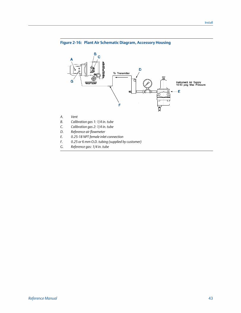
Plant Air Schematic Diagram, Accessory HousingFigure 2-16:
A. VentB. Calibration gas 1: 1/4 in. tubeC. Calibration gas 2: 1/4 in. tubeD. Reference air flowmeterE. 0.25-18 NPT female inlet connectionF. 0.25 or 6 mm O.D. tubing (supplied by customer)G. Reference gas: 1/4 in. tube
Install
Reference Manual 43
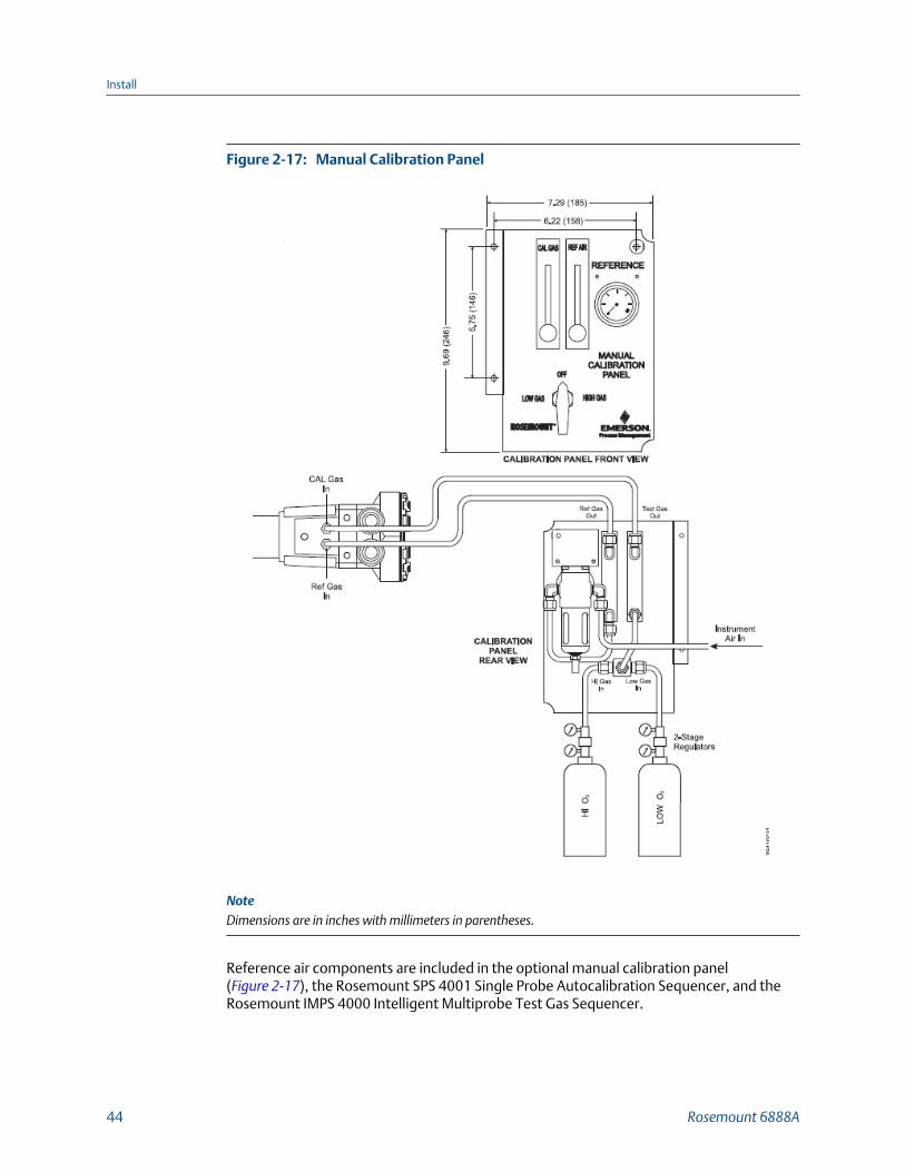
Manual Calibration PanelFigure 2-17:
NoteDimensions are in inches with millimeters in parentheses.
Reference air components are included in the optional manual calibration panel(Figure 2-17), the Rosemount SPS 4001 Single Probe Autocalibration Sequencer, and theRosemount IMPS 4000 Intelligent Multiprobe Test Gas Sequencer.
Install
44 Rosemount 6888A
NOTICE
The optional Rosemount SPS 4001B or Rosemount IMPS 4000 Sequencer can only be usedwhen the Rosemount 6888Xi advanced electronics option is selected. The Rosemount 6888Ximust be properly configured for autocalibration. See Chapter 3.
See the SPS 4001B Single Probe Autocalibration Sequencer Instruction Manual or the IMPS 4000 Intelligent Multiprobe Test Gas Sequencer Instruction Manual for wiring andpneumatic connections.
2.4.2 Calibration gasTwo calibration gas concentrations are used with this transmitter, low gas - 0.4% O2,balance N2, and high gas - 8% O2, balance N2.
CAUTION!
CALIBRATION READING ERRORS
Do not use 100% nitrogen as a low gas (zero gas). Emerson suggests that gas for the low (zero)be between 0.4% and 2.0% O2. Do not use gases with hydrocarbon concentrations of more than40 parts per million. Failure to use proper gases will result in erroneous readings.
CAUTION!
EQUIPMENT DAMAGE
If the ducts will be washed down during outage, MAKE SURE to power down the Rosemount6888A units and remove them from the wash areas.
NOTICE
Upon completing installation, make sure that the transmitter is turned on and operating priorto firing up the combustion process. Damage can result from having a cold unit exposed to theprocess gases. During outages, if possible, leave all units running to prevent condensation andpremature aging from thermal cycling.
An optional manual calibration panel is shown in Figure 2-17. See Figure 2-18 for theRosemount 6888A probe calibration gas connection ports.
Install
Reference Manual 45

Rosemount 6888A Calibration Gas ConnectionsFigure 2-18:
A. Cal gas inB. Ref air ventC. Ref air in
Traditional Architecture Cable Gland AssemblyFigure 2-19:
Install
46 Rosemount 6888A
3 Configuration, startup, and operation
WARNING!
ELECTRIC SHOCKInstall all protective equipment covers and safety ground leads before equipment startup.Failure to install covers and ground leads could result in serious injury or death.
CAUTION!
EQUIPMENT DAMAGE
If external loop power is used, the power supply must be a safety extra low voltage (SELV)type.
3.1 Power up Rosemount 6888 Transmitterwithout Rosemount 6888XiComplete the following steps to apply power to the Rosemount 6888 Transmitter withoutconnecting it to the Rosemount 6888Xi.
1. Apply AC line power to the transmitter.
2. Apply 24 Vdc loop power to the transmitter.
3. Using either the DCS control or a Field Communicator, verify communications to thetransmitter.
The transmitter probe takes approximately 45 minutes to warm up to the 736 °C(1357 °F) heater setpoint. The 4-20 mA signal remains at a default value of 3.5 mA,and the O2 reading remains at 0% through this warm-up period. After warm-up, theprobe begins reading oxygen, and the 4-20 mA output is based on the default rangeof 0-10% O2.
If there is an error condition at startup, an alarm message is displayed.
Configuration, startup, and operation
Reference Manual 47
3.2 Power up the Rosemount 6888 Transmitterwith single/dual channel or single channel andflame safety interlock Rosemount 6888XiComplete the following steps to power up the Rosemount 6888 Transmitter with single/dual channel or single channel and flame safety interlock Rosemount 6888Xi.
1. Appy AC line power to the transmitter.
2. Apply AC line power to the Rosemount 6888Xi. Run the Rosemount 6888Xi QuickStart Wizard (Section 3.4). At the Auto Cal Device screen, select the calibrationmethod based on the Rosemount 6888 Transmitter as follows:
a. Standard probe housing configuration - Select None, SPS, or IMPS as appropriate.Do not select Integral or calibration will not be possible.
b. Integral autocal probe housing - Select Integral only. If Integral is not selected,calibration will not be possible.
3. Verify communications between the transmitter and the Rosemount 6888Xi.
The Rosemount 6888Xi display is preconfigured to display O2 and cell temperaturefor single channel configurations and both O2 readings for dual channelconfigurations.
The transmitter probe takes approximately 45 minutes to warm up to the 736 °C (1357 °F)heater setpoint. The 4-20 mA signal remains at a default value of 3.5 mA, and the O2reading remains at 0% through this warm-up period. After warm up, the probe beginsreading oxygen, and the 4-20 mA output is based on the default range of 0-10% O2.
If there is an error condition at startup, an alarm message is displayed on the Rosemount6888Xi.
3.3 Power up the Rosemount 6888 directreplacement probe (no electronics inside) withtraditional architecture Rosemount 6888XiComplete the following steps to power up the Rosemount 6888 direct replacement probewith the Rosemount 6888Xi Electronics.
1. Apply AC line power to the Rosemount 6888Xi.
2. Run the Quick Start Wizard as described in Section 3.4.
3. At the Auto Cal Device screen, select None, SPS, or IMPS as appropriate.
Do not select Integral or calibration will not be possible.
The transmitter probe takes approximately 45 minutes to warm up to the 736 °C (1357 °F)heater setpoint. The 4-20 mA signal remains at a default value of 3.5 mA, and the O2reading remains at 0% through this warm-up period. After warm up, the probe beginsreading oxygen, and the 4-20 mA output is based on the default range of 0-10% O2.
Configuration, startup, and operation
48 Rosemount 6888A

If there is an error condition at startup, an alarm message is displayed on the Rosemount6888Xi.
3.4 Rosemount 6888Xi Quick Start WizardWhen the Rosemount 6888Xi is first powered, a short wizard program guides you throughthe basic setup. Once configured, the Rosemount 6888Xi retains the setup, and the wizardwill not repeat.
1. Apply power to the Rosemount 6888Xi.
Once boot-up is complete, the Quick Start Wizard screen appears. With a dualchannel Rosemount 6888Xi, the wizard runs for both channels in succession.
2. Press Enter to continue.
3. At the Sensor Type screen, use the Up and Down keys to select O2.
Do not select CO as this option is reserved for future use.
4. Press Enter to continue.
5. At the Device Type screen use the Up and Down keys to select HART® or FF(FOUNDATION™ Fieldbus), whichever applies.
6. At the Auto Cal Device screen, use the Up and Down keys to select the calibrationmethod to be used. The methods are defined as follows:
• None - Manual calibration with the standard probe housing configuration
• SPS - Automatic calibration with the standard probe housing configuration usingthe Rosemount SPS 4001B
• IMPS - Automatic calibration with the standard probe housing configurationusing the Rosemount IMPS
• Integral - Automatic calibration with the integral autocal probe housingconfiguration
7. Press Enter to continue.
NOTICEIf SPS, IMPS, or Integral is selected, you must still configure automatic calibration as On.Other parameters, such as test gas values and gas times, should be verified as well. Referto the Rosemount 6888Xi Reference Manual for calibration setup details.
8. When prompted by Setup Correct?, use the Up and Down keys to select Yes.
If you select No, the wizard restarts.
9. Press Enter to continue.
The Rosemount 6888Xi displays several screens while saving the configuration, resetsitself, and then returns to the main screen.
Configuration, startup, and operation
Reference Manual 49
3.5 Re-initiating Rosemount 6888Xi wizardTo re-initiate the wizard setup, you must reset the I/O board to default factory conditions.
1. Apply power to the Rosemount 6888Xi.
2. When the main screen appears, press Menu several times until the System menuappears. Use the Up and Down keys to select Configure IOB. Press Enter to continue.
3. When the Configure IOB screen appears, use the Up and Down keys to select I/OBoard 1. With a dual channel Rosemount 6888Xi, you can reset and reconfigureeither or both I/O boards. Press Enter to continue.
4. When the I/O board 1 menu appears, use the Up and Down keys to select Reset I/OBoard. Press Enter to continue.
5. When the Reset menu appears, use the Up and Down keys to select Factory Defaults.Press Enter to continue.
6. When prompted, use the Up and Down keys to select Yes. Press Enter to continue.
The Rosemount 6888Xi displays several screens while saving the configuration, resetsitself, and then displays the Wizard screen.
3.6 CalibrationThe Rosemount 6888 O2 analyzer system can be calibrated in the installed conditionwithout removing the instrument from the process duct and also while the combustionprocess is on-line. A stainless steel tube runs the length of the probe and delivers thecalibration gases into the cell area. Factory calibration is usually satisfactory for initialstartup and operation, but the most accurate measurement is gained by executing acalibration under normal operating conditions.
Emerson recommends using 0.4% O2 and 8% O2 as calibration gases, with a balance ofnitrogen in the gas bottles, but other values can be used as long as the electronics areconfigured identically. Do not use instrument air or pure nitrogen as calibration gas values.Use a two-stage pressure regulator to establish a pressure of 20 psi from the bottles andset the flowmeter to 5 scfh flow rate.
3.6.1 Manual/semi-automatic calibrationThe Rosemount 6888 probe with the standard housing can be calibrated in a semi-automatic fashion with a technician following prompts via the display of the Rosemount6888Xi Electronics or via HART communications to a Field Communicator or AMS console.The technician needs to manually switch the gases based upon these prompts. Emersonrecommends using 0.4% O2 and 8% O2, balance nitrogen as calibration gases. Always use atwo-stage pressure regulator set to 20 psi. Set the calibration gas flowmeter for amaximum of 5 scfh with the cal gas fitting removed from the probe. A diffuser/filter that isplugged over time may cause the flowmeter to deliver less flow to the sensing cell, butnever readjust the flow rate until a new diffuser is installed. Readjusting the flowmeterback up to the 5 scfh level could pressurize the cell during calibration and cause the O2reading to shift downwards.
Configuration, startup, and operation
50 Rosemount 6888A

The electronics determine if the calibration was successful and calculate new calibrationvalues. New calibration values are not automatically loaded into the electronics after asuccessful calibration, however. The technician has the opportunity to accept or reject thenew values. (A significant calibration change may cause a bump in the O2 readings at theDCS console, causing operator concern). Record the calibration data on a log (cell slope,constant, and impedance, as well as the speed of response data). If the electronics is used,it stores calibration data for the past 10 successful calibrations.
CAUTION!
READING ERRORS
Make sure the calibration gas cap is replaced tightly after calibration is complete. A loose ormissing cap can permit fresh air to bias the O2 readings high in processes that run at negativepressure.
3.6.2 Fully automatic calibrationFor fully automatic calibration, the Rosemount 6888Xi Electronics must manage theactuation of solenoids to introduce gases into the probe.
Rosemount 6888 probes with standard electronics housingIn addition to the Rosemount 6888Xi, this arrangement requires a separate single probesequencer (SPS), which is a solenoid box for switching calibration gases, or a largerintelligent multiprobe sequencer (IMPS), which can handle the autocal for up to fourprobes in one box.
The automatic calibration can be initiated in several ways:
• Via a calibration recommended diagnostic that is periodically checking cellimpedance
• Via push button on the Rosemount 6888Xi electronics
• Via HART communications from a 475 handheld communicator or AMS
• Via an external contact closure
• Via time since the last successful calibration
If the O2 measurement is being used for automatic control, always place the O2 controlloop into manual prior to calibrating. Always inform the operator prior to calibrating. TheRosemount 6888Xi Electronics provides an in cal contact closure for this purpose. Aninitiate cal contact is also provided.
The Rosemount 6888Xi Electronics sequences the calibration gases in turn into the sensingcell.A 300 second flow time is the factory default for both gases and also for the purgecycle, which lets the probe signal come back to the normal flue gas readings. The 4-20 mAsignal representing O2 can be held during the calibration cycle or permitted to vary withthe bottled gases, in which case a record of the calibration can be trended at the DCS.
Calibration setup is found under the detailed setup menu.
Configuration, startup, and operation
Reference Manual 51

Rosemount 6888 probe with integral autocal housingThis probe contains the autocal solenoids within the blue electronics housing, eliminatingthe need and cost for an SPS or IMPS solenoid enclosure. Both calibration gases arepermanently piped into two ports on the probe. It's important to confirm that there are nopiping leaks or the calibration bottles will leak down prematurely.
NoteThe calibration sequence from the Rosemount 6888Xi electronics will be identical to that formanual/semiautomatic calibration, but with the integral auto cal version of this probe it is notpossible to conduct a manual calibration. The factory offers a probe rebuild capacity if solenoid orother failures occur.
NoteCalibration gas bottles are piped and under pressure at all times, so be sure to leak-check all fittings,tubings, and connections. Always use dual-stage pressure regulators.
3.6.3 Other features associated with calibration1. Cal check capability: You can choose to look at new calibration values prior to having
them load in and become active. If this feature is selected, a calibrationchanged alarm comes up after the calibration is complete. Push the Diagnosticsbutton on the Rosemount 6888Xi to require an Accept Cal step so that thetechnician or operator can decide if they are ready to accept a potentially largechange in calibration values.
2. Plugged diffuser diagnostic: This feature measures the return-to-process rate aftercalibration gases are removed and will alarm when this tiem exceeds 75% of thepurge time configured. A purge time too short alarm indicates that thediagnostic could not work because of a short purge time and is another indicationthat the diffuser is plugged. Increase purge time in this case.
Another feature that comes with the plugged diffuser diagnostic is auto gasswitching. This feature switches cal gases and also ends the purge sequence whenthe readings settle out, vs. waiting for a configured flow time. This saves time andgas.
3. Tolerance check: Alarms if the cell MV signal is significantly different from theexpected signal of the bottles noted in the setup. This indicates if the wrong bottlesare being used or if a bottle runs out in the middle of a calibration.
Calibration setup is under the Detailed Setup menu.
Calibration setup can be found in the Rosemount 6888Xi menu.
For the factory default menu, see Figure 3-1.
Configuration, startup, and operation
52 Rosemount 6888A

Calibration DefaultsFigure 3-1:
Configuration, startup, and operation
Reference Manual 53
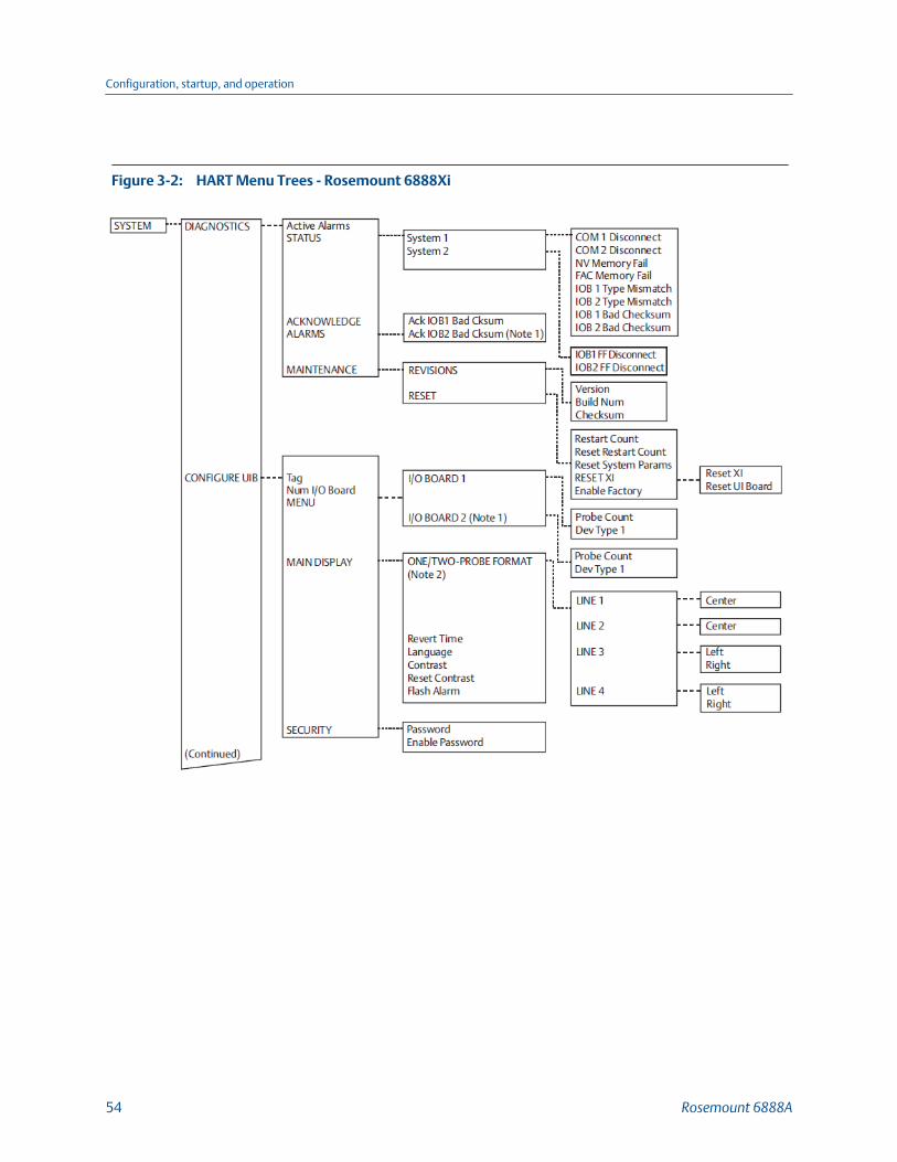
HART Menu Trees - Rosemount 6888XiFigure 3-2:
Configuration, startup, and operation
54 Rosemount 6888A

Configuration, startup, and operation
Reference Manual 55

Configuration, startup, and operation
56 Rosemount 6888A
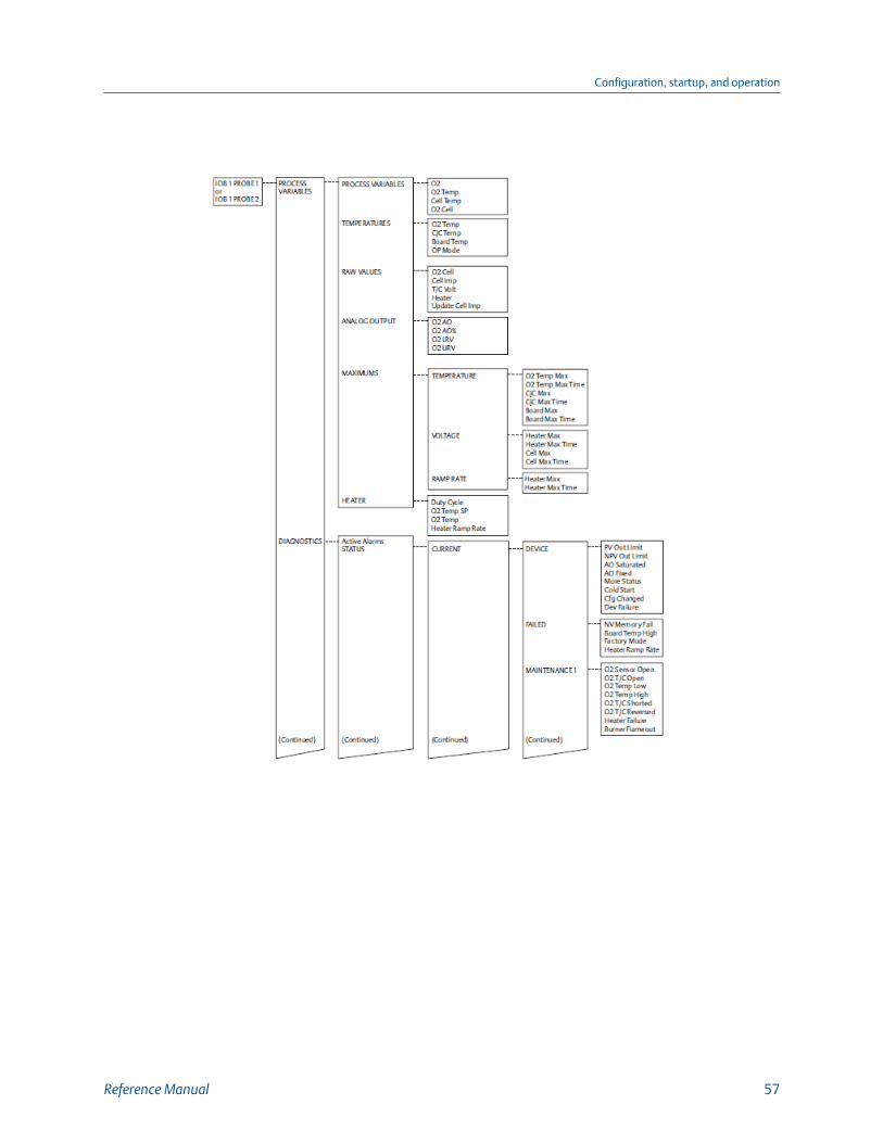
Configuration, startup, and operation
Reference Manual 57

Configuration, startup, and operation
58 Rosemount 6888A
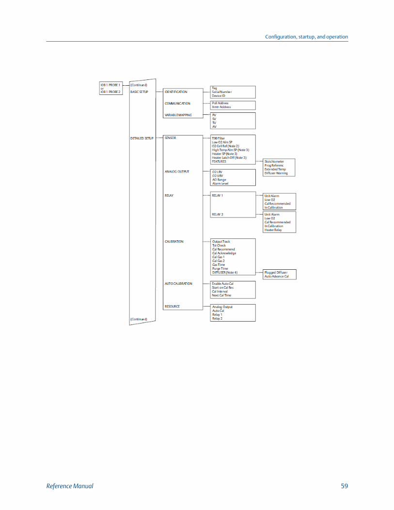
Configuration, startup, and operation
Reference Manual 59
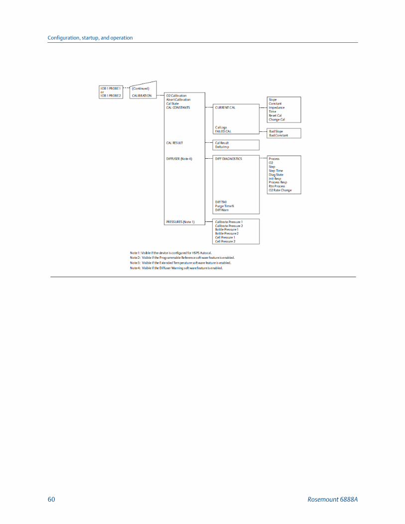
Configuration, startup, and operation
60 Rosemount 6888A

HART Menu Trees - 375/475 Field CommunicatorFigure 3-3:
Configuration, startup, and operation
Reference Manual 61

Configuration, startup, and operation
62 Rosemount 6888A

Configuration, startup, and operation
Reference Manual 63
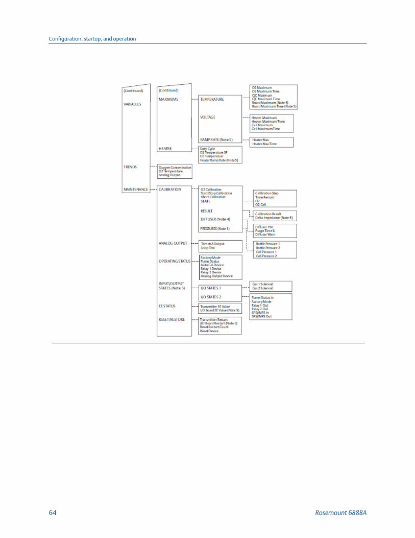
Configuration, startup, and operation
64 Rosemount 6888A
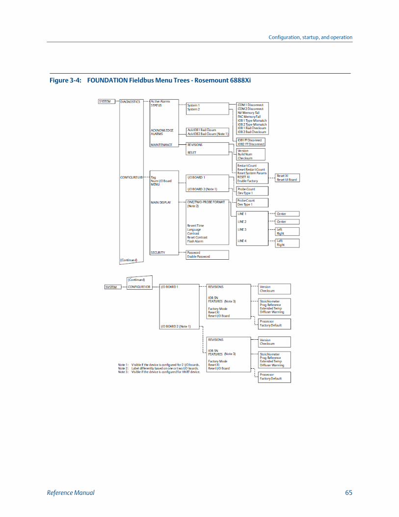
FOUNDATION Fieldbus Menu Trees - Rosemount 6888XiFigure 3-4:
Configuration, startup, and operation
Reference Manual 65

Configuration, startup, and operation
66 Rosemount 6888A

Configuration, startup, and operation
Reference Manual 67
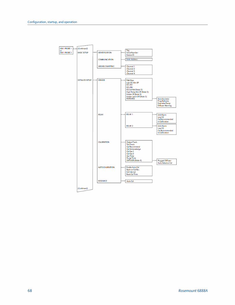
Configuration, startup, and operation
68 Rosemount 6888A

Configuration, startup, and operation
Reference Manual 69
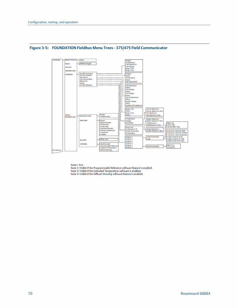
FOUNDATION Fieldbus Menu Trees - 375/475 Field CommunicatorFigure 3-5:
Configuration, startup, and operation
70 Rosemount 6888A

Configuration, startup, and operation
Reference Manual 71
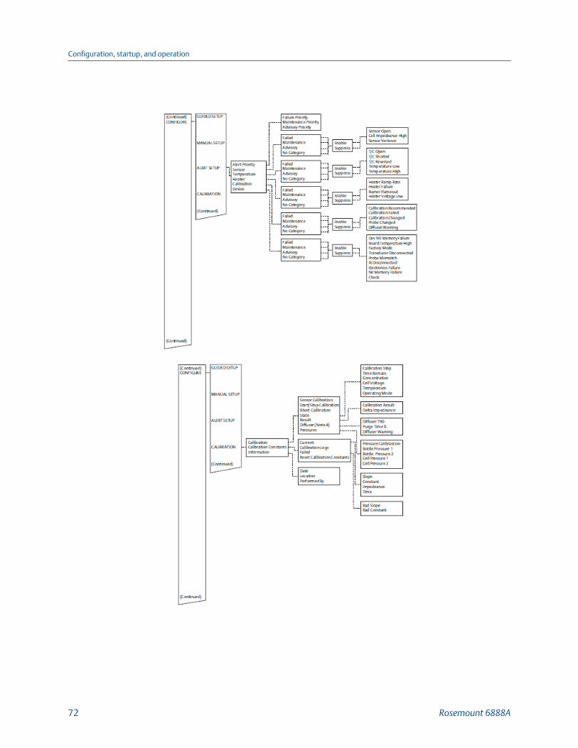
Configuration, startup, and operation
72 Rosemount 6888A
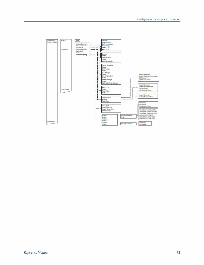
Configuration, startup, and operation
Reference Manual 73

Configuration, startup, and operation
74 Rosemount 6888A

3.7 StartupThe transmitter begins operation when the signal wiring is connected and heater power issupplied to the transmitter. First power the AC line voltage to the heater and then powerthe 24 Vdc power/signal loop for the transmitter electronics.
The O2 probe takes approximately 45 minutes to warm up to the 736 °C (1357 °F) heatersetpoint. The 4-20 mA signal remains at a default value of 3.5 mA through this warmupperiod. Once warm, the O2 reads oxygen, and the 4-20 mA signal's reading is based on thedefault range of 0-10% O2.
3.7.1 Error conditionsIf there is an error condition at startup, an alarm message is displayed. Refer to Chapter 4 todetermine the cause of the error. Clear the error and cycle power. The %O2 andtemperature display should return without the alarm message.
Configuration, startup, and operation
Reference Manual 75

3.8 System parameter descriptionsAmong the parameters available through the 375/475 Communicator menus are anumber of system parameters. The system parameters define variables that configure aspecific probe in the transmitter system. System parameters are described in the followingtable.
System ParametersTable 3-1:
Parameter name Unit Description
O2 % Current oxygen concentration value (O2 %). The valueshould reflect the last good O2 value if it is in the Lock stateduring calibration.
O2 Temp °C Current O2 sensor temperature.
CJC Temp °C Current cold junction temperature.
O2 Cell mV Raw mV value for O2 sensor.
Cell Imp ohm Cell impedance/sensor resistance measured.
Heater V Heater voltage.
O2AO mA Analog output value represents the O2 concentrationmeasurement.
O2 Temp Max °C This is the highest O2 sensor temperature reached sincelast reset.
O2 Temp Max Time Days ago Time stamp of the highest O2 sensor temperature reachedsince last reset.
Temperature | CJC Max °C This is the highest temperature reached at the cold junc-tion since last reset.
Temperature | CJC Max Time Days ago Time stamp of the highest temperature reached at thecold junction since last reset.
Voltage | Heater Max °C This is the highest heater voltage reached since last reset.
Voltage | Heater Max Time Days ago Time stamp of the highest heater voltage reached sincelast reset.
Voltage | Cell Max °C This is the highest cell voltage reached since last reset.
Voltage | Cell Max Time Days ago Time stamp of the highest cell voltage reached since lastreset.
OP Mode -- Device operating mode:
PO = Power up
WU = Warm up (analog output is railed)
NM = Normal operation
CA = Calibrating (analog output can be tracking or lockedat last good value based on AO Tracks configuration)
AL = Alarm detected (recoverable)
SF = Alarm detected (non-recoverable)
Active alarms -- Current alarms (see Chapter 4)
Configuration, startup, and operation
76 Rosemount 6888A

System Parameters (continued)Table 3-1:
Parameter name Unit Description
Device -- Alarm state
Failed -- Alarm state: On/OffNV Memory Fail, Board Temp High, FactoryMode, Heater Ramp Rate
Maintenance 1 -- Alarm state: On/OffO2 Sensor Open, O2 T/C Open, O2 Temp Low, O2 TempHigh, O2 T/C Shorted, O2 T/C Reversed, Heater Fail-ure, Burner Flameout
Maintenance 2 -- Alarm state: On/OffXmtr Disconnect, Cal Recommended, CalFailed, Cell Imp High, Probe Mismatch
Advisory -- Alarm state:
Xmtr Disconnect, Cal Recommended, CalFailed, Cell Imp High, Probe Mismatch
Duty Cycle -- O2 heater duty cycle. Value between 0 and 1.
O2 Temp SP °C PID temperature set point.
Heater Ramp Rate °C/sec Heater ramp rate calculated in °C per second.
Operating Status -- Device configuration: On/OffFactory Mode, Flame Status (IO Board DIP Switch
setting), Auto Cal Device, Relay 1 Device, Re-lay 2 Device, AO Device
Xmtr EE Val -- Transmitter board nonvolatile memory diagnostic.
Xmtr Restart -- Software restart count for the transmitter.
HART | Device Rev -- HART device revision number.
Transmitter | Version -- Software version number for the transmitter.
Tag -- Device tag: Up to 8 characters long.
Serial Number -- Probe serial number.
Device ID -- Unique device ID number. (HART)
PV -- Primary variable assignment: O2 (HART).
SV -- Secondary variable assignment: Cell imp (HART).
TV -- Third variable assignment: Cell imp (HART).
4V -- Fourth variable assignment: O2 cell (HART).
Xmtr Address -- Transmitter board polling address.
O2 LRV % Primary variable (O2%) lower range value.
O2 URV % Primary variable (O2%) upper range value.
Configuration, startup, and operation
Reference Manual 77

System Parameters (continued)Table 3-1:
Parameter name Unit Description
Alarm Level -- O2 alarm level
0 = 3.5 mA
1 = 21.1 mA
Cal Gas 1 % Test gas 1 value. This is the actual value of the gas beingapplied during the Test Gas 1 phase of a calibration.
Cal Gas 2 % Test gas 2 value. This is the actual value of the gas beingapplied during the Test Gas 2 phase of a calibration.
Gas Time sec Test gas application time. This is the length of time testgases are applied to the O2 probe during low or high testgas phase of a calibration.
Purge Time sec Test gas purge time. This is the length of time before theoutput will be returned to the process reading after a cali-bration.
Slope mV/Dec Current calibration slope. This is the slope value that wascalculated as a result of the last successful calibration.
Constant mV Current calibration constant. This is the constant valuethat was calculated as a result of the last successful calibra-tion.
Impedance ohm Cell impedance. This is the sensor resistance that was cal-culated as a result of the last successful calibration.
Time Days ago Time stamp of the last successful calibration.
Cal Logs | Slope mV/Dec Previous calibration slope. There are ten calibration results.1 is the most recent, and 10 is the least recent calibration
slope.
Cal Logs | Constant mV Previous calibration constant. There are ten calibration re-sults. 1 is the most recent, and 10 is the least recent cali-
bration constant.
Cal Logs | Impedance ohm Previous cell impedance. This is the sensor resistance thatwas calculated as a result of a previous successful calibra-tion. There are ten calibration results. Index 1 is the
most recent, and Index 10 is the least recent sensor re-
sistance measured.
Cal Logs | Time Days ago Time stamp of the previous successful calibration. Thereare ten calibration time stamps. Index 1 is the most re-
cent, and Index 10 is the least recent time stamp.
Configuration, startup, and operation
78 Rosemount 6888A

System Parameters (continued)Table 3-1:
Parameter name Unit Description
Cal Result -- Calibration result:
0 = None
1 = Success
2 = Failed constant
3 = Failed slope
4 = Failed temperature
5 = Gas 1 tolerance error
6 = Gas 2 tolerance error
7-10 (future)
11 = AutoCal no resp
12 = AutoCal out of sync
13 = AutoCal abort
14 = No solenoid
15 = Warmup abort
16 = Alarm abort
3.9 Parameter setup
3.9.1 Test gas valuesUse a Field Communicator to set test gas values for calibration. A Rosemount 6888Ashipped from the factory has test gas values for low and high set to 0.4% and 8.0%respectively. Perform this same process any time a transmitter board is replaced.
1. Use the 375/475 Field Communicator to access the main HART menu.
2. From the main menu, select CONFIGURE.
3. From the CONFIGURE menu, select MANUAL SETUP.
4. From the MANUAL SETUP menu, select CALIBRATION.
5. From the CALIBRATION menu, select GAS 1.
6. Press the Right key to edit the gas value.
7. Use the stylus to enter the new gas value. Then press ENTER when finished.
8. Use the stylus to select SEND to update the Rosemount 6888A.
9. Repeat steps 5 through 8 for Gas 2.
3.9.2 Set test gas timesUse a Field Communicator to set test gas flow time and purge time for calibration.
Configuration, startup, and operation
Reference Manual 79

A Rosemount 6888A shipped from the factory has test gas flow time and purge time set to300 seconds. You must complete the same process any time a transmitter board isreplaced.
Procedure
1. Use the 375/475 Field Communicator to access the main HART menu.
2. From the main menu, select CONFIGURE.
3. From the CONFIGURE menu, select MANUAL SETUP.
4. From the MANUAL SETUP menu, select CALIBRATION.
5. From the CALIBRATION menu, select GAS TIME.
6. Press the Right key to edit the gas value.
7. Use the stylus to enter the new gas value; then press ENTER when finished.
8. Use the stylus to select SEND to update the Rosemount 6888A.
9. From the GAS TIME menu, select PURGE TIME.
10. Press the Right key to edit the gas value.
11. Use the stylus to enter the new gas value; then press ENTER when finished.
12. Use the stylus to select SEND to update the Rosemount 6888A.
3.9.3 Track output during calibrationUse a Field Communicator to set how the analog output value will function duringcalibration.A Rosemount 6888A shipped from the factory has output tracking set to No, i.e., theanalog output holds the last value during the calibration cycle. You must perform thissame process any time a transmitter board is replaced.
Procedure
1. Use the 375/475 Field Communicator to access the main HART menu.
2. From the main menu, select CONFIGURE.
3. From the CONFIGURE menu, select MANUAL SETUP.
4. From the MANUAL SETUP menu, select CALIBRATION.
5. From the CALIBRATION menu, select ANALOG OUTPUT TRACK.
6. Press the Right key to edit, then the Up and Down keys to select YES or NO.
• No - The analog output holds the last value during calibration.
• Yes - The analog output tracks the actual measurement during calibration.
7. Use the stylus to press ENTER when finished.
8. Use the stylus to select SEND to update the Rosemount 6888A.
Configuration, startup, and operation
80 Rosemount 6888A
3.9.4 Configure analog outputThe analog output signal from the Rosemount 6888A can be configured for the 4-20 mArange and fault condition. A separate configuration is set up when the Rosemount 6888Ais used with the optional Rosemount 6888Xi Advanced Electronics. When the Rosemount6888A is used without the Rosemount 6888Xi, this parameter must be set to NO. If it is setto YES and a Rosemount 6888Xi is not connected, the Rosemount 6888A triggers an alarmand forces the analog output to the fault level. If the Rosemount 6888A is used later with aRosemount 6888Xi, the Rosemount 6888Xi automatically sets this parameter to YES.
An Rosemount 6888A shipped from the output has the analog outputs set to 4 to 20 mArange with a 3.5 mA alarm level. You must complete the same process any timetransmitter board is replaced.
1. Use the 375/475 Field Communicator to access the main HART menu.
2. From the main menu, select CONFIGURE.
3. From the CONFIGURE menu, select MANUAL SETUP.
4. From the MANUAL SETUP menu, select ANALOG OUTPUT.
5. From the ANALOG OUTPUT menu, select from the following parameters; then pressENTER.
• O2 LRV: O2 value at lower analog output value (0% at 4 mA, non-configurable)
• O2 URV: O2 value at upper analog output value (50% max at 20 mA)
• Output Range: Range of analog output (4-20 mA, non-configurable)
• Alarm level: O2 alarm level (3.5 mA or 21.1 mA)
• Xi Mode: Selects whether or not the Rosemount 6888A is used with a Rosemount6888Xi (should always be set to NO for a stand-alone Rosemount 6888A)
6. Use the stylus to enter the value; then press ENTER when finished.
7. Use the stylus to select SEND to update the Rosemount 6888A.
3.10 CalibrateNew O2 cells may operate for more than a year without requiring calibration, but oldercells may require calibration every few weeks as they near the end of their life.
A CALIBRATION RECOMMENDED alarm provides notice of when a calibration is required.This strategy ensures that the O2 reading is always accurate and eliminates manyunnecessary calibrations based on calendar days or weeks since previous calibration.
You can calibrate the Rosemount 6888A transmitter manually through the handheld375/475 Field Communicator or the optional Rosemount 6888Xi. Fully automaticcalibration can be performed using the optional Rosemount 6888Xi advanced electronicsand the Rosemount SPS4001B Single Probe Autocalibration Sequencer or the RosemountIMPS 4000 Intelligent Multiprobe Sequencer.
Configuration, startup, and operation
Reference Manual 81

3.10.1 Calibration procedureThis section covers manual calibration. For automatic calibration details, see theinstruction manual for the Rosemount SPS 4001B Single Probe Autocalibration Sequenceror the Rosemount IMPS 4000 Intelligent Multiprobe Test Gas Sequencer.
1. Use the 375/475 Field Communicator to access the main HART menu.
2. From the main menu, select CONFIGURE.
3. From the CONFIGURE menu, select CALIBRATION.
4. From the CALIBRATION menu, again select CALIBRATION.
5. From the CALIBRATION menu, select O2 CALIBRATION.
WARNING!Failure to remove the Rosemount 6888A from automatic control loops prior toperforming this procedure may result in a dangerous operating condition.
Calibration Method - SimplifiedFigure 3-6:
6. In the first screen, a Loop should be removed from automatic controlwarning occurs. Remove the Rosemount 6888A from any automatic loop controls toavoid a potentially dangerous operating condition. Press OK when ready.
7. At the next screen, when the step shows APPLY GAS 1, press OK to continue.
8. When Flow Gas 1 and Read Gas 1 are complete and the step shows APPLY GAS 2,press OK to continue.
9. When Flow Gas 2 and Read Gas 2 are complete and the step shows STOP GAS,press OK to continue the calibration with purge.
10. When the screen shows Loop may be returned to automatic control,press OK to return to the CALIBRATION screen.
11. At the CALIBRATION menu, select RESULT.
At the RESULT menu, the results of the calibration are displayed. In the event thecalibration cycle fails, the reason is displayed here as well. The calibration results aredescribed as follows:
Configuration, startup, and operation
82 Rosemount 6888A

• Success: Calibration completed successfully.
• Failed Constant: The calculated calibration constant is outside the range of±20.00.
• Failed Slope: The calculated calibration slope is outside the range of 34.5 to 57.5.
• WarmUp Abort: Attempted to perform a calibration during warmup.
• Alarm Abort: Another alarm occurred and caused the calibration cycle to abort.
12. In the event of a calibration failure, do the following:
a. From the RESULT menu, press HOME to return to the main menu.
b. From the main menu, select SERVICE TOOLS.
c. From the OVERVIEW menu, select ALERTS.
d. Frpom the ALERTS menu, select ACTIVE ALERTS.
The ACTIVE ALERTS menu should contain an A: CALIBRATION FAILED alarm.
e. Press the Left key to return to the ALERTS menu.
f. From the ALERTS menu, select DEVICE STATUS.
g. From the DEVICE STATUS menu, select ACKNOWLEDGE.
h. From the ACKNOWLEDGE menu, select ACK CALIBRATION FAILED.
When the process is complete, the system returns to the ACKNOWLEDGE menu.
3.10.2 Calibration logThe Rosemount 6888A stores the current and 10 previous calibrations. The stored dataincludes the slope, constant, cell impendance, and time (in days) since that calibration.The log can be accessed as follows:
Using the Field Communicator: Configure > Calibration > Calibration Constants >Calibration Logs.
When first entering the log, the screen displays Calibration 1. This is the most recentprevious calibration, not the current calibration. Calibration 0 displays the currentcalibration. Use the keypad or communicator keys to navigate through the logs. Thefactory default for log entries is a slope of 50.00 mV/Dec and a constant of 0.00 mV. Anylog entries with these values means there have not been at least 10 calibrations performedto fill the entire log.
3.10.3 Reset calibrationThe Rosemount 6888A can reset the current calibration and replace it with the previouscalibration. You may reset the calibration in cases where the calibration was known tocontain invalid values. Resetting a calibration transfers the slope and constant fromcalibration 1 in the log into the calibration 0 position. The cell impedance and days sincecalibration remain unchanged.
Configuration, startup, and operation
Reference Manual 83

Reset the calibration as follows:
WARNING!
Failure to remove the Rosemount 6888A from automatic control loops prior to performing thisprocedure may result in a dangerous operating condition.
Using the Field Communicator: Configure > Calibration > Calibration Constants > ResetCalibration Constants.
Follow the instructions on the screen to complete the reset function.
3.11 D/A trimThe D/A trim procedure is used the calibrate the 4-20 mA output signal to a precision mAmeasurement device. Only the signal to the DCS needs to be trimmed.
1. Use the 375/475 Field Communicator to access the main HART menu.
2. From the main menu, select SERVICE TOOLS.
3. From the SERVICE TOOLS menu, select MAINTENANCE.
4. From the MAINTENANCE menu, select ANALOG OUTPUT.
5. From the ANALOG OUTPUT menu, select TRIM mA OUTPUT.
In the first screen, a Loop should be removed from automatic controlwarning occurs.
WARNING!Failure to remove the Rosemount 6888A from automatic control loops prior toperforming this procedure may result in a dangerous operating condition.
6. Remove the Rosemount 6888A from any automatic control loops to avoid apotentially dangerous operating condition. Press OK when ready.
7. Follow the prompts on the 375/475 to perform the trim.
8. Use the stylus to enter the new measured analog output value; then press ENTER toaccept.
9. When trim is complete, press OK to return to the ANALOG OUTPUT menu.
Configuration, startup, and operation
84 Rosemount 6888A
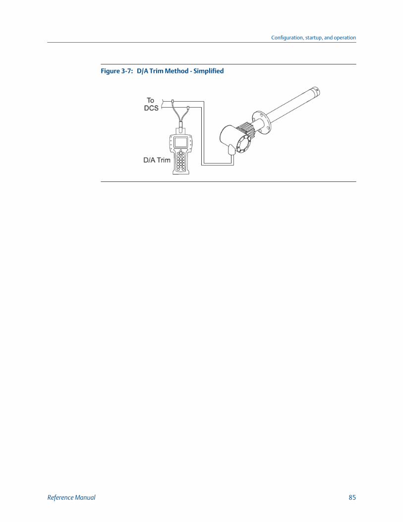
D/A Trim Method - SimplifiedFigure 3-7:
Configuration, startup, and operation
Reference Manual 85

Configuration, startup, and operation
86 Rosemount 6888A
4 Troubleshooting
4.1 OverviewWhen the zirconium oxide sensing cell is heated to its setpoint [736 °C (1357 °F)], the cellgenerates a voltage that represents the difference between the process O2 % and thereference O2 % inside the probe (20.95% O2 instrument or ambient air).
When flowing calibration gases, the raw cell millivolt value should represent the levels onthe chart in Figure 4-1. Note that the raw cell millivolt value increases logarithmically as theO2 concentration decreases.
Troubleshooting
Reference Manual 87
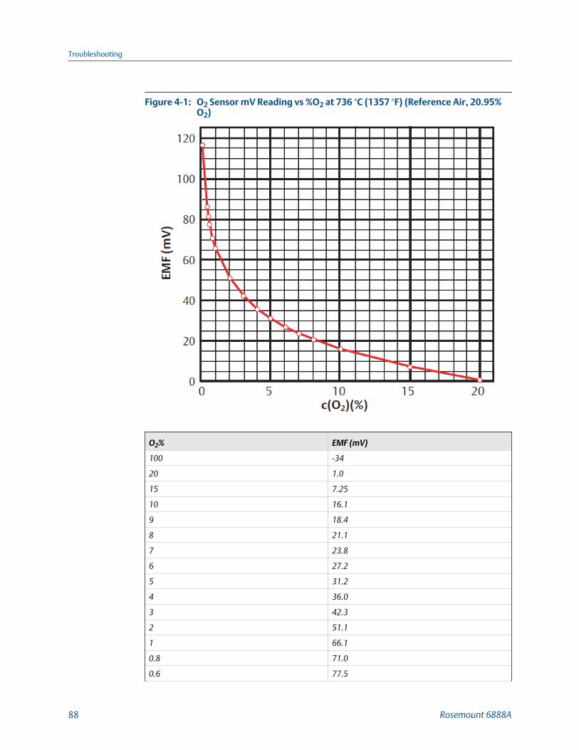
O2 Sensor mV Reading vs %O2 at 736 °C (1357 °F) (Reference Air, 20.95%O2)
Figure 4-1:
O2% EMF (mV)
100 -34
20 1.0
15 7.25
10 16.1
9 18.4
8 21.1
7 23.8
6 27.2
5 31.2
4 36.0
3 42.3
2 51.1
1 66.1
0.8 71.0
0.6 77.5
Troubleshooting
88 Rosemount 6888A

O2% EMF (mV)
0.5 81.5
0.4 86.3
0.2 101.4
0.1 116.6
0.01 166.8
4.2 General
WARNING!
ELECTRIC SHOCKInstall all protective equipment covers and ground leads after troubleshooting. Failure toinstall covers and ground leads could result in serious injury or death.
Consider the following equipment conditions, features, and requirements whentroubleshooting a problem.
4.2.1 GroundingIt is essential that adequate grounding precautions are taken when installing the system.
Thoroughly check both the probe and electronics to ensure the grounding quality has notdegraded during fault finding. The system provides facilities for 100% effective groundingand total elimination of ground loops.
4.2.2 Electrical noiseThe transmitter has been designed to operate in the type of environment normally foundin a boiler room or control room.
Noise suppression circuits are employed on all field terminations and main inputs. Whenfault finding, evaluate the electrical noise being generated in the immediate circuitry of afaulty system. Ensure all cable shields are connected to earth.
4.2.3 Electrostatic dischargeElectrostatic discharge can damage ICs in the electronics.
Before removing or handling the processor board or the ICs, ensure you are at groundpotential.
Troubleshooting
Reference Manual 89
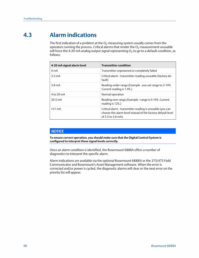
4.3 Alarm indicationsThe first indication of a problem at the O2 measuring system usually comes from theoperators running the process. Critical alarms that render the O2 measurement unusablewill force the 4-20 mA analog output signal representing O2 to go to a default condition, asfollows:
4-20 mA signal alarm level Transmitter condition
0 mA Transmitter unpowered or completely failed
3.5 mA Critical alarm - transmitter reading unusable (factory de-fault)
3.8 mA Reading under range (Example - you set range to 2-10%.Current reading is 1.9%.)
4 to 20 mA Normal operation
20.5 mA Reading over range (Example - range is 0-10%. Currentreading is 12%.)
>21 mA Critical alarm - transmitter reading is unusable (you canchoose this alarm level instead of the factory default levelof 3.5 to 3.6 mA).
NOTICE
To ensure correct operation, you should make sure that the Digital Control System isconfigured to interpret these signal levels correctly.
Once an alarm condition is identified, the Rosemount 6888A offers a number ofdiagnostics to interpret the specific alarm.
Alarm indications are available via the optional Rosemount 6888Xi or the 375/475 FieldCommunicator and Rosemount's Asset Management software. When the error iscorrected and/or power is cycled, the diagnostic alarms will clear or the next error on thepriority list will appear.
Troubleshooting
90 Rosemount 6888A
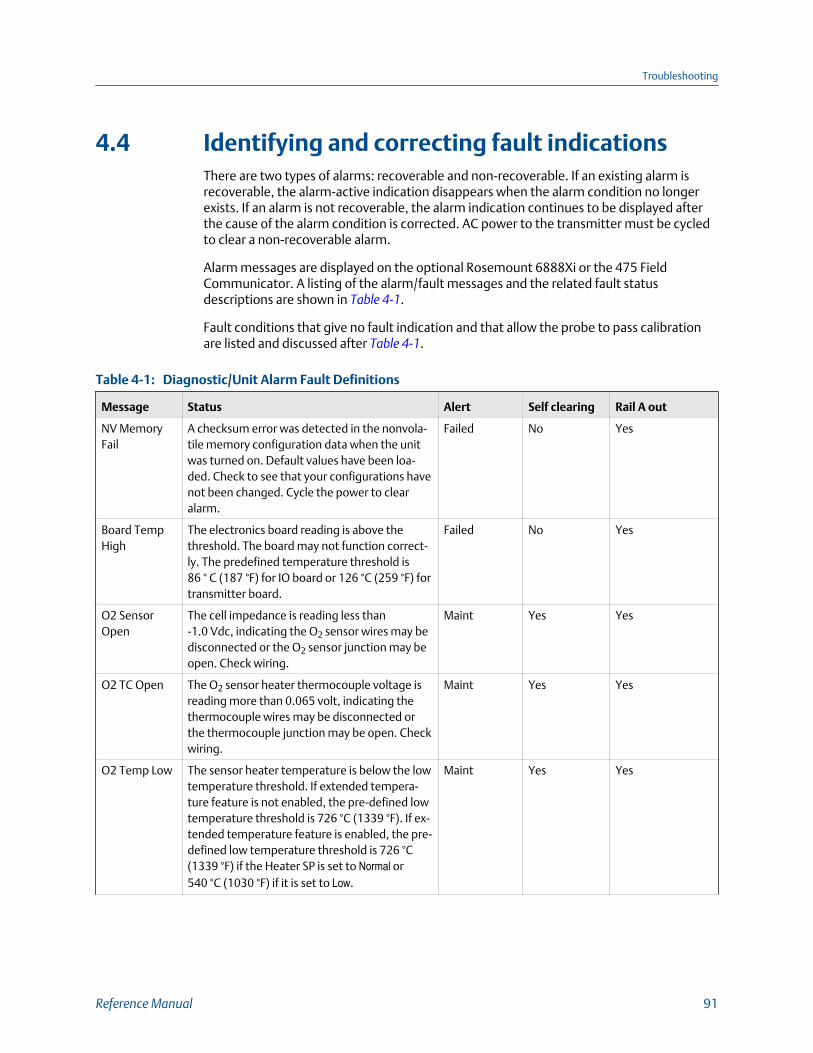
4.4 Identifying and correcting fault indicationsThere are two types of alarms: recoverable and non-recoverable. If an existing alarm isrecoverable, the alarm-active indication disappears when the alarm condition no longerexists. If an alarm is not recoverable, the alarm indication continues to be displayed afterthe cause of the alarm condition is corrected. AC power to the transmitter must be cycledto clear a non-recoverable alarm.
Alarm messages are displayed on the optional Rosemount 6888Xi or the 475 FieldCommunicator. A listing of the alarm/fault messages and the related fault statusdescriptions are shown in Table 4-1.
Fault conditions that give no fault indication and that allow the probe to pass calibrationare listed and discussed after Table 4-1.
Diagnostic/Unit Alarm Fault DefinitionsTable 4-1:
Message Status Alert Self clearing Rail A out
NV MemoryFail
A checksum error was detected in the nonvola-tile memory configuration data when the unitwas turned on. Default values have been loa-ded. Check to see that your configurations havenot been changed. Cycle the power to clearalarm.
Failed No Yes
Board TempHigh
The electronics board reading is above thethreshold. The board may not function correct-ly. The predefined temperature threshold is86 ° C (187 °F) for IO board or 126 °C (259 °F) fortransmitter board.
Failed No Yes
O2 SensorOpen
The cell impedance is reading less than-1.0 Vdc, indicating the O2 sensor wires may bedisconnected or the O2 sensor junction may beopen. Check wiring.
Maint Yes Yes
O2 TC Open The O2 sensor heater thermocouple voltage isreading more than 0.065 volt, indicating thethermocouple wires may be disconnected orthe thermocouple junction may be open. Checkwiring.
Maint Yes Yes
O2 Temp Low The sensor heater temperature is below the lowtemperature threshold. If extended tempera-ture feature is not enabled, the pre-defined lowtemperature threshold is 726 °C (1339 °F). If ex-tended temperature feature is enabled, the pre-defined low temperature threshold is 726 °C(1339 °F) if the Heater SP is set to Normal or540 °C (1030 °F) if it is set to Low.
Maint Yes Yes
Troubleshooting
Reference Manual 91

Diagnostic/Unit Alarm Fault Definitions (continued)Table 4-1:
Message Status Alert Self clearing Rail A out
O2 Temp High The heater temperature is above the definedtemperature threshold. If extended tempera-ture feature is not enabled, the pre-defined hightemperature threshold is 750 °C (1382 °F). If ex-tended temperature feature is enabled, thehigh temperature threshold is defined by theHigh Temp Alm SP parameter.
Maint Yes Yes
No
O2 T/C Shor-ted
This diagnostic is only intended to detect a cop-per short of the thermocouple connections atthe electronic connector. The cell heater T/Cvoltage is reading close to zero, indicating thethermocouple wires may be shorted.
Maint Yes Yes
O2 T/C Re-versed
The O2 sensor heater temperature thermocou-ple voltage is reading a negative voltage, indi-cating the thermocouple wire connections maybe reversed. Check wiring.
Maint Yes Yes
Cal Failed A calibration error occurred during the last cali-bration. Check the cal result for more details.Acknowledge calibration failed or recalibrate toclear alarm.
Maint Yes No
Cell Imp High The O2 sensor impedance/cell resistance valuemeasurement is greater than 2000 Ohms, indi-cating the cell may be beyond its useful life.
Maint Yes No
Xi Disconnect It indicates using transmitter's AO when con-nected to Rosemount 6888Xi and Rosemount6888Xi is disconnected.
Maint Yes Yes
Htr VoltageLow
The heater voltage for the O2 heater is below 30volts. Check heater power.
Adv Yes No
4.5 Calibration passes, but still reads incorrectlyThere are a few fault conditions where no alarm indication is present and the probe passescalibration, but the O2 reading may still be incorrect.
An incorrect flow rate of calibration gases can cause a shifted calibration. If the flow rate ofcalibration gases is too low, process gases can mix in with the calibration gases, causing amixture at the cell that is different from what is noted on the calibration gas bottles.Always set the calibration flow rate when a new diffuser is installed and never readjust thisflow rate until another new diffuser is installed. For applications with heavy particulateloading, see Section 4.5.2.
If reference air is not supplied or is improperly supplied, the calibration may readincorrectly.
Troubleshooting
92 Rosemount 6888A

4.5.1 Probe passes calibration, O2 still reads high
External reference air leakThere may be a leak that is permitting ambient air to mix with the process gases. Sincemany combustion processes are slightly negative in pressure, ambient air can be drawninto the cell area, biasing the O2 reading upward.
1. Make sure that the calibration gas is capped tightly between calibrations.
2. If autocal is used, make sure the check valve is sealing properly.
Probe Leakage PathsFigure 4-2:
A. Cal gas 1/4 in. tubeB. Ref gas 1/4 in. tubeC. Vent
3. If an abrasive shield is uses, a small leak at the probe flange can migrate down theannular space between the probe OD and shield ID to the sensing cell, causing afalse high O2 reading.
Internal reference air leakSee Figure 4-2. There may be a leak inside the O2 probe itself, permitting the reference air(20.95% O2) to mix with the process gases at the cell. To confirm this leak condition,pressurize the inside (reference side) of the probe by plugging the reference air exhaustport with your finger for one minute. (The conduit ports where the signal and power wirespass may also need to be sealed.) The O2 reading should decrease slightly. If the O2reading increases during this test, there is a leak inside the probe.
1. Acid condensation inside the probe can degrade the hose that carries the cal gas tothe cell. Inspect this hose. Dislodging or improper installation of the cal gas orreference air hose can cause a leakage path.
2. The sensing cell is fastened to the end of the probe tube and uses a corrugatedwasher to separate the process gases from the ambient reference air. Thecorrugated washer may be damaged by corrosion. Discard used washer.
Troubleshooting
Reference Manual 93
NOTICE
Always install a new corrugated washer whenever you remove the sensing cell from the probe.
Bad reference side cell electrode
A bad reference side cell electrode can cause an elevated O2 reading. This fault is usuallyindicated by a frequent Calibration Recommended alarm and increasing cellimpedance readings. A high cell impedance can be calibrated out, but if the impedancecontinues to increase rapidly, the sensing cell must be replaced.
4.5.2 Probe passes calibration, O2 still reads lowThe diffusion element at the end of the probe is a passive filter. It plugs very slowly,because there is no active flow being drawn across it. In applications that have a heavyparticulate loading (coal or wood fired boilers, cement and lime kilns, catalystregeneration, recovery boilers, etc.) this diffusion element will eventually plug.
NOTICE
It is important not to pressurize the sensing cell during calibrations by flowing excessive calgas against a plugged diffuser. Always use a two-stage regulator for setting calibration gaspressure. Calibration flow rates should be set only when a new diffuser is installed. As thediffuser plugs, do not adjust the flow rates upward.
4.5.3 How do I detect a plugged diffuser?The O2 cell's speed of response will degrade. The O2 trend in the control room will becomesmoother.
When calibrating, the calibration gas flow rate will be noted to be lower. Never readjustthis flow upwards to correct for a plugged diffuser. Adjust this flow only when a newdiffuser is installed.
Always note the time it takes for the cell to recover to the normal process value after thecal gas is removed. As the diffuser plugs, this recovery time will get longer and longer. Usea calibration record to record and track calibration response times.
The Rosemount 6888Xi Advanced Electronics is available with an enhanced softwarefeature to automatically characterize the rate of diffuser pluggage during a calibrationcycle.
4.5.4 Can I calibrate a badly plugged diffuser?It may not be possible to immediately replace a plugged diffuser while the process is on-line.
Troubleshooting
94 Rosemount 6888A
You can calibrate the probe without pressurizing the cell by adjusting the calibration gasflow rate downward before calibration. For instance, say the process is at 3%, and the firstcalibration gas is 8%. Adjust the flow of cal gas downward until the reading begins tomigrate from 8% to lower values, indicating that the process gases are now mixing with thecalibration gases.
Adjust the flow rate back up until this mixing is just eliminated. Calibrate at this flow rate.Replace the diffuser at the first opportunity.
WARNING!
ELECTRIC SHOCKInstall all protective equipment covers and safety ground leads after troubleshooting. Failureto install covers and ground leads could result in serious injury or death.
Troubleshooting
Reference Manual 95

Troubleshooting
96 Rosemount 6888A

5 Maintenance and service
5.1 OverviewThis section identifies the calibration methods available and provides the procedures tomaintain and service the Rosemount 6888A O2 transmitter.
WARNING!
ELECTRIC SHOCKInstall all protective equipment covers and safety ground leads after equipment repair orservice. Failure to install covers and ground leads could result in serious injury or death.
5.2 Maintenance intervalsThe maintenance interval required is variable, depending on the ambient and processconditions the analyzer is exposed to. The zirconium oxide sensing cell is non-depletingand has no specific shelf life or a defined life in flue gas operation. The sensitivity of asensing cell that is mounted inside a boiler that is burning natural gas may shift slightlyover several years. Acidic compounds are the main aggressors to the sensing cell, typicallySO2, resulting from sulfur contained in coal and heavy oil fuels, and also HCl from thecombustion of plastics in municipal incinerators and in industrial thermal oxidizers.Sensing cells may experience significant degradation and signal shift in this type of service,particularly if the operating levels of O2 are very low (below 1% O2).
A calibration check is generally recommended on a quarterly basis (every three months) byflowing bottled gas to the probe. (Make sure the operations personnel are notified whendoing this and also make sure that the O2 control loop is placed in manual mode). If theprobe readings vary significantly from the bottle values, conduct a formal calibration asnoted in Chapter 3.
The optional Rosemount 6888Xi offers a calibration recommended diagnostic thatindicates when the probe needs to be calibrated.
Combustion processes that have a high level of ash or other particulate content will causethe diffusion element on the end of the probe to plug off. A significantly plugged diffusercauses a slower speed of response to changing O2 levels in the process. This can usually beseen on the recorded trends in the control room.
When performing a calibration check or actual calibration, the calibration flow meter mayread lower if the diffuser is significantly plugged. Never increase the flow rate back-up,however, as this can cause a shifted calibration. Adjust the calibration flow rate only whena new diffuser is installed. Always record the response time back to the process after thecalibration gases are removed. Diffuser plugging can be tracked through the calibrationrecord.
Maintenance and service
Reference Manual 97

Visually inspect the probe during plant outages, paying particular attention to condensedcomponents. Condensation can be reduced or eliminated by insulating the probeinstallation, including the probe mount, flange, and blue housing.
5.3 CalibrateThe Rosemount 6888A O2 transmitter can be calibrated manually through the handheld375/475 Field Communicator or automatically through the Rosemount SPS4001 SingleProbe Autocalibration Sequencer or the Rosemount IMPS 4000 Intelligent Multiprobe TestGas Sequencer and the Rosemount 6888Xi Advanced Electronics.
5.3.1 Manual calibrationRefer to Section 3.6.1 to perform a manual calibration.
5.3.2 Automatic calibrationContact from the Rosemount 6888Xi Advanced Electronics to a Rosemount SPS4001B(one per probe) or Rosemount IMPS4000 (up to four probes) provides the ability tomanually initiate a calibration at any time from the control room. The Rosemount 6888Xiinterface must be used with the Rosemount SPS4001B or Rosemount IMPS4000 in orderto perform an auto/semi-auto calibration. Refer to the Rosemount SPS4001B or Rosemount IMPS4000 instruction manual for further details on how to configure andperform an automatic calibration.
5.4 RepairEach of the following procedures details how to remove and replace a specific componentof the Rosemount 6888A.
WARNING!
BURNSRemove the transmitter from the stack for all service activities. Allow the unit to cool and takeit to a clean work area. Failure to comply may cause severe burns.
WARNING!
ELECTRIC SHOCKDisconnect and lock out power before working on any electrical components. There is voltageup to 240 Vac.
Maintenance and service
98 Rosemount 6888A

5.4.1 Remove and replace probe
Remove probeComplete the following steps to remove the probe from the stack.
1. Turn off power to the system.
2. Shut off the calibration gases at the cylinder and the instrument air.
3. Disconnect the calibration gas and instrument air lines from the transmitter.
4. Remove housing cover.
5. Remove all signal and power wiring to the probe.
6. Remove insulation to access the mounting probe.
7. Unbolt the transmitter from the stack and take it to a clean work area.
8. Allow the unit to cool to a comfortable working temperature.
Replace probeComplete the following steps to replace the probe in the stack.
1. Bolt the transmitter to the stack and install the insulation.
2. Connect all signal and power leads at the probe.
Refer to Chapter 2 for detailed wiring instructions.
3. Connect the calibration gas and instrument air lines to the probe.
4. Install the housing cover.
5. Turn on instrument air.
6. Restore power to the system.
Refer to Chapter 3.
NOTICERecalibration is required whenever the electronic cards or sensing cell are replaced.
5.4.2 Replace transmitter boardThe transmitter board is not repairable and must be replaced if any component fails.See Figure 5-1 for item number references. The transmitter board is available as astandalone kit or with the plastic cover and mounting plate.
WARNING!
ELECTRIC SHOCKDisconnect and lock out power before working on any electrical components.
Maintenance and service
Reference Manual 99
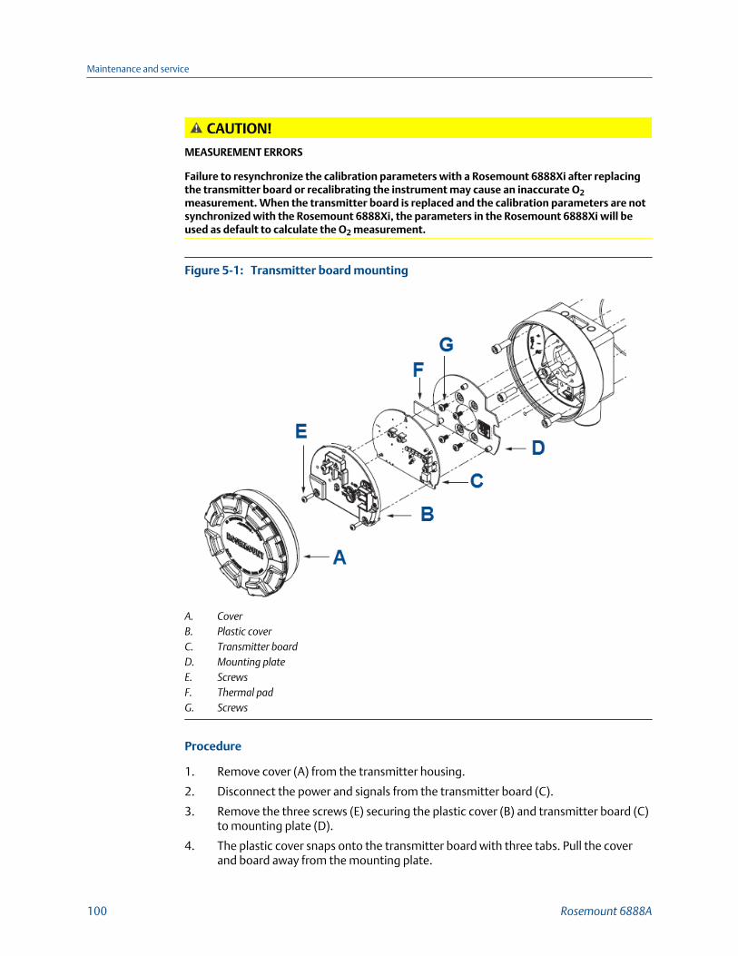
CAUTION!
MEASUREMENT ERRORS
Failure to resynchronize the calibration parameters with a Rosemount 6888Xi after replacingthe transmitter board or recalibrating the instrument may cause an inaccurate O2measurement. When the transmitter board is replaced and the calibration parameters are notsynchronized with the Rosemount 6888Xi, the parameters in the Rosemount 6888Xi will beused as default to calculate the O2 measurement.
Transmitter board mountingFigure 5-1:
A. CoverB. Plastic coverC. Transmitter boardD. Mounting plateE. ScrewsF. Thermal padG. Screws
Procedure
1. Remove cover (A) from the transmitter housing.
2. Disconnect the power and signals from the transmitter board (C).
3. Remove the three screws (E) securing the plastic cover (B) and transmitter board (C)to mounting plate (D).
4. The plastic cover snaps onto the transmitter board with three tabs. Pull the coverand board away from the mounting plate.
Maintenance and service
100 Rosemount 6888A
The thermal pad (F) will most likely remain attached to the mounting plate.
5. Disconnect the two wire harness connectors from the back of the transmitter boardand remove the plastic cover and transmitter board.
Replacement transmitter boards come in two configurations:
a. Transmitter board with thermal pad and mounting screws
b. Transmitter board, thermal pad, plastic cover, mounting plate, and mountingscrews
6. If only the transmitter board is being replaced, carefully unsnap the plastic coverfrom the old transmitter board and then snap it onto the new board.
The cover goes in one way only with the screw terminals for the power and signalwiring fitting into the openings in the cover.
If the transmitter board, plastic cover, and mounting plate are being replaced, theplastic cover should already be snapped onto the transmitter board.
7. Remove the old thermal pad from the mounting plate. Attach the new thermal padto the mounting plate 1 in. up from the flat edge of the pad.
Do not reassemble without the thermal pad in place. If the transmitter board, plasticcover, and mounting plate are being replaced, the thermal pad should already be inplace on the mounting plate.
8. If the mounting pad is being replaced, remove the four screws (H) securing the plateto the housing. Install the new mounting plate using four screws.
Replacement screws are provided if any become lost or damaged.
9. Reconnect the two wire harness connectors to the back of the transmitter board.
The connectors are different and individually keyed to prevent misconnection.
10. Carefully push the wire harnesses through the hole in the mounting plate and alignthe transmitter board with plastic cover over the three standoffs on the mountingplate.
11. Install the three screws to secure the board to the mounting plate.
Replacement screws are provided if any become lost or damaged.
12. Reconnect the power and signal wires to the transmitter board.
13. Reinstall the cover to the transmitter housing.
14. Reapply power to the transmitter. Prior to using the transmitter for measurementpurposes, perform one of the following:
• Transmitter without Rosemount 6888Xi: Recalibrate the transmitter. See Chapter 3.
• Transmitter with Rosemount 6888Xi: When initialization is complete, thetransmitter begins to heat up, but an alarm condition is shown on theRosemount 6888Xi. Synchronize the calibration parameters via the Rosemount6888Xi as follows:
a. Press DIAG once to view the alarms. A Probe Changed alarm appears.
b. Press EXIT once to enter the Diagnostic menu.
Maintenance and service
Reference Manual 101
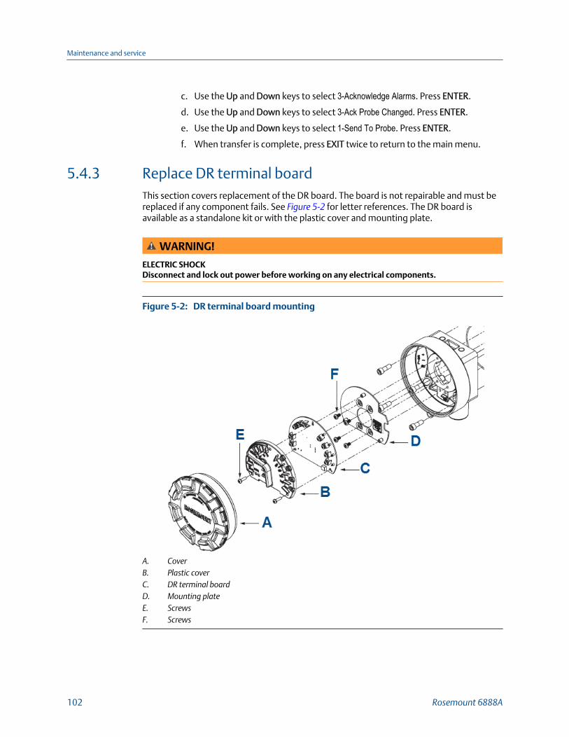
c. Use the Up and Down keys to select 3-Acknowledge Alarms. Press ENTER.
d. Use the Up and Down keys to select 3-Ack Probe Changed. Press ENTER.
e. Use the Up and Down keys to select 1-Send To Probe. Press ENTER.
f. When transfer is complete, press EXIT twice to return to the main menu.
5.4.3 Replace DR terminal boardThis section covers replacement of the DR board. The board is not repairable and must bereplaced if any component fails. See Figure 5-2 for letter references. The DR board isavailable as a standalone kit or with the plastic cover and mounting plate.
WARNING!
ELECTRIC SHOCKDisconnect and lock out power before working on any electrical components.
DR terminal board mountingFigure 5-2:
A. CoverB. Plastic coverC. DR terminal boardD. Mounting plateE. ScrewsF. Screws
Maintenance and service
102 Rosemount 6888A

Procedure
1. Remove cover (A) from the DR probe housing.
2. Disconnect the power and signal wires from the DR terminal board (C).
3. Remove the three screws (E) securing the plastic cover (B) and DR terminal board (C)to mounting plate (D).
4. Disconnect the two wire harness conenctors from the back of the transmitter board.
Replacement DR terminal boards come in two configurations:
a. DR terminal board with thermal pad and mounting screws
b. DR terminal board, thermal pad, plastic cover, mounting plate, and mountingscrews
5. If the mounting pad is being replaced, remove the four screws (F) securing the plateto the housing. Install the new mounting plate using four screws.
Replacement screws are provided if any become lost or damaged.
6. Reconnect the two wire harness connectors to the back of the DR terminal board.
The connectors are different and individually keyed to prevent misconnection.
7. Carefully push the wire harnesses through the hole in the mounting plate and alignthe DR terminal board with plastic cover over the three standoffs on the mountingplate.
8. Install the three screws to secure the board to the mounting plate.
Replacement screws are provided if any become lost or damaged.
9. Reconnect the power and signal wires to the transmitter board.
10. Reinstall the cover to the DR probe housing.
11. Reapply power to the DR probe.
5.4.4 Heater strut replacementThis section covers heater strut replacement. Do not attempt to replace the heater strutuntil all other possibilities for poor performance have been considered.If heater strut replacement is needed, order a replacement heater strut kit (Table 6-1).Refer to Figure 5-3 for item letter references.
WARNING!
BURNSUse heat resistant gloves and clothing when removing probe. Do not attempt to work on theprobe until it has cooled to room temperature. The probe can be as hot as 427 °C (800 °F). Thiscan cause severe burns.
Maintenance and service
Reference Manual 103

Housing/Strut Exploded ViewFigure 5-3:
A. CoverB. Plastic coverC. Transmitter boardD. Mounting plateE. ScrewsF. Thermal padG. ScrewsH. Strut clampI. O-ringJ. ScrewsK. Viton tubeL. Tube clamp
Procedure
1. Follow the instructions in Section 5.4.1 to remove the transmitter from the stack orduct.
2. Follow the instructions in Section 5.4.2 or Section 5.4.3 to remove the electronicsfrom the housing.
3. Remove four screws (E). Remove housing from probe using care not to damage thestrut wire harnesses or O-ring (I).
4. Remove the strut clamp (H) from inside the finned housing on the probe.
5. Remove tube clamps (L) and Viton tubes (K) from the CAL and REF gas ports and theCAL and REF gas lines. Leave the clamps in place on the hoses for later reassembly.
6. Grasp the wire loop and carefully slide the heater strut assembly out of the probetube.
Maintenance and service
104 Rosemount 6888A

7. When replacing the strut, orient the probe so that the small calibration gas tube is atthe 6 o'clock position of the probe tube. Align the slot on the heater plate with thecalibration gas line in the probe tube. Slide the strut into the probe tube.
It turns to align the hole on the back plate of the strut with the calibration gas line.When the hole and calibration gas line are aligned correctly, the strut slides in therest of the way.
8. As the strut insertion nears completion, install the guide rod into the calibration gastube to assist in guiding the calibration gas tube through the hole in the end of thestrut.
9. Replace the CAL and REF gas Viton tubes (K).
10. Insert the strut clamp (H) back into the finned housing on the probe.
The opening should be down to allow for clearance for the gas tubes.
11. Carefully install the O-ring (I) back into the groove between the two housings.
A small amount of silicone grease may be used to hold the O-ring in place. Do notuse petroleum based grease.
12. Insert the strut wire harnesses into the housing.
13. Turn the conduit ports of the housing to the CAL and REF gas ports side of the probeand position the housing on the probe.
14. Install and tighten the four screws (J).
15. Follow the instructions in Section 5.4.2 to install the electronics into the housing.
16. Follow the instructions in Section 5.4.1 to install the transmitter into the stack orduct.
5.4.5 Cell replacementThis section covers oxygen sensing cell replacement. Do not attempt to replace the celluntil all other possibilities for poor performance have been considered.If cell replacement is needed, order the cell replacement kit (Table 6-1).
The cell replacement kit (Figure 5-4) contains a cell and flange assembly, corrugated seal,setscrews, socket head cap screws, and anti-seize compound. The items are carefullypackaged to preserve precise surface finishes. Do not remove items from the packaginguntil they are ready to be used. Spanner wrenches and hex wrenches needed for thisprocedure are part of an available special tools kit (Table 6-1).
WARNING!
BURNSUse heat-resistant gloves and clothing when removing the probe. Do not attempt to work onthese components until they have cooled to room temperature. Probe components can be ashot as 300 °C (572 °F). This can cause severe burns.
Disconnect and lock out power before working on any electrical components. There is voltageup to 240 Vac.
Maintenance and service
Reference Manual 105

CAUTION!
EQUIPMENT DAMAGE
Do not remove the cell unless you are certain it needs to be replaced. Removal may damage thecell and platinum pad. Follow the complete troubleshooting procedure to make sure the cellneeds to be replaced before removing it.
Cell Replacement KitFigure 5-4:
A. ANSI gasketB. Wire and pad assemblyC. Anti-seize compoundD. 22 gauge wireE. Closed end connectorF. Set screwsG. Teflon tubingH. Socket head cap screwsI. Cell and flange assemblyJ. Corrugated sealK. Probe (not included in kit)L. Calibration gas passage
Maintenance and service
106 Rosemount 6888A

Procedure
1. Follow the instructions in Section 5.4.1 to remove the transmitter from the stack orduct.
2. If the probe uses the standard diffusion element, use a wrench to remove thediffuser assembly.
3. If equipped with the optional ceramic diffusion assembly, remove and discard thesetscrews and remove the vee deflector. Use spanner wrenches from the probedisassembly kit (Table 6-1) to turn the hub free from the retainer. Inspect thediffusion element. If damaged, replace the element.
4. Loosen the four socket head cap screws from the cell and flange assembly andremove the assembly and the corrugated seal.
The cell flange has a notch that may be used to gently pry the flange away from theprobe. The contact pad inside of the probe sometimes fuses to the oxygen sensingcell. If the cell is fused to the contact pad, push the cell assembly back into the probe(against spring pressure) and quickly twist the cell assembly. The cell and contactpad should separate. If the contact pad stays fused to the cell, a new contact/thermocouple assembly must be installed. Disconnect the cell and thethermocouple wires at the crimp connections and withdraw the cell with the wiresstill attached.
5. If the contact assembly is damaged, replace the strut or contact pad. Follow theinstructions in Section 5.4.4, steps 2 through 4, to remove the electronics housingand then follow the instructions for replacing the contact pad provided in the cellreplacement kit.
6. Remove and discard the corrugated seal. Clean the mating faces of the probe tubeand retainer. Remove burrs and raised surfaces with a block of wood and crocuscloth. Clean the threads on the retainer and hub.
7. Rub a small amount of anti-seize compound on both sides of the new corrugatedseal.
8. Assemble the cell and flange assembly, corrugated seal, and probe tube. Make surethe calibration tube lines up with the calibration gas passage in each component.Apply a small amount of anti-seize compound to the screw threads and use thescrews to secure assembly. Torque to 60 in.-lb (6.8 N m).
9. Follow the instructions in Section 5.4.4, steps 9 through 15, to reassemble theelectronics housing.
10. Apply anti-seize compound to the threads of the cell assembly, hub, and setscrews.Reinstall the hub on the cell assembly. Using pin spanner wrenches, torque to10 ft-lb (14 N m). If applicable, reinstall the vee deflector, orienting apex toward gasflow. Secure with setscrews and anti-seize compound. Torque to 25 in-lb (2.8 N m).
11. On systems equipped with an abrasive shield, install the dust gaskets with joints180 ° apart.
12. Follow the instructions in Section 5.4.1 to install the transmitter to the stack or duct.
13. Turn on power and monitor thermocouple output.
It should stabilize at 29.3 ±0.2 mV. Set reference air flow at 1 l/min (2 scfh). After thetransmitter stabilizes, calibrate the probe. If new components have been installed,repeat calibration after 24 hours of operation.
Maintenance and service
Reference Manual 107

5.4.6 Diffusion element replacementThe diffusion element protects the cell from particles in process gases. Normally, it doesnot need to be replaced, because the vee deflector protects it from particulate erosion.In severe environments, the diffusion element may be broken or subject to excessiveerosion. Examine the element whenever removing the probe for any purpose. Replace ifdamaged.
Damage to the diffusion element may become apparent during calibration. Compareprobe response with previous response. A broken diffusion element will cause aninadequate response to calibration gas. Hex wrenches needed to remove setscrews andsocket head screws in the following procedure are available as part of a probe disassemblykit, Table 6-1.
NOTICE
This refers to the ceramic diffusion element only.
Maintenance and service
108 Rosemount 6888A

Ceramic diffuser element replacementFigure 5-5:
A. RetainerB. Spanner wrenchC. Optional ceramic diffusion elementD. Set screwE. Vee deflectorF. Cement filletG. Cement portH. Hub
Procedure
1. Follow the instructions in Section 5.4.1 to remove the probe from the stack or duct.
2. Loosen set screws (D) using the hex wrench from the probe disassembly kit andremove the vee deflector (E). Inspect sets crews. If damaged, replace with stainlesssets crews coated with anti-seize compound.
3. Follow the instructions in Section 5.4.1 to install the probe into the stack or duct.
Maintenance and service
Reference Manual 109
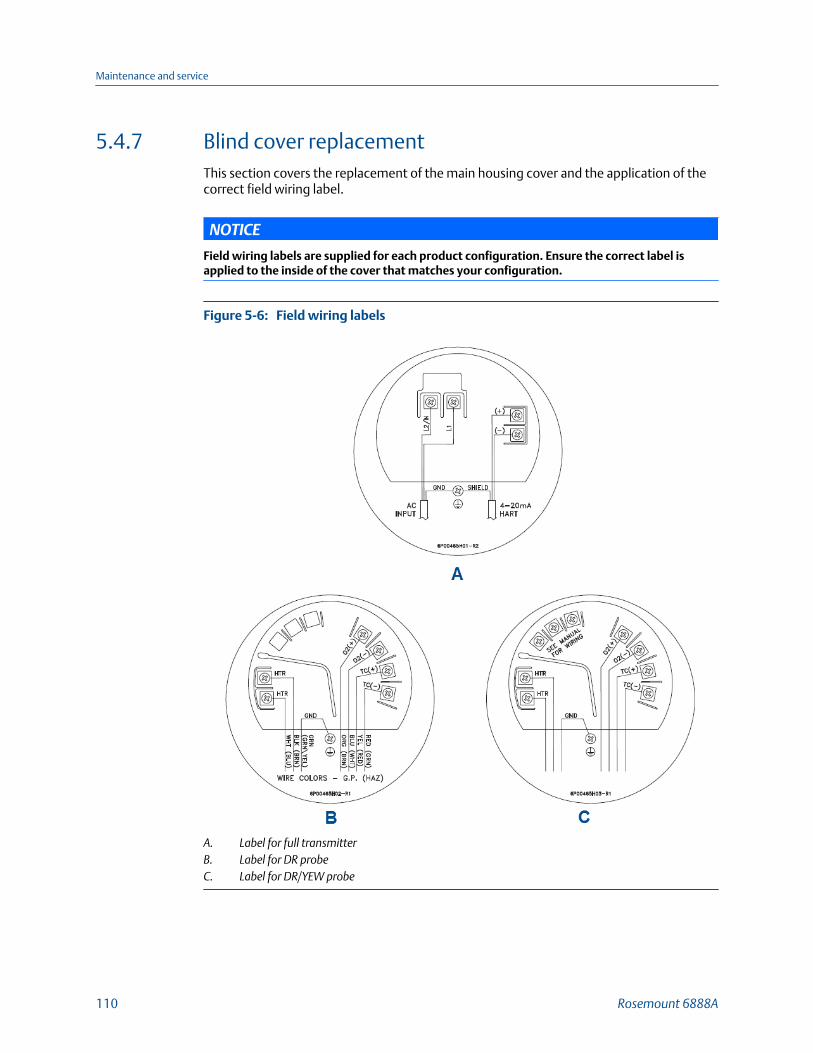
5.4.7 Blind cover replacementThis section covers the replacement of the main housing cover and the application of thecorrect field wiring label.
NOTICE
Field wiring labels are supplied for each product configuration. Ensure the correct label isapplied to the inside of the cover that matches your configuration.
Field wiring labelsFigure 5-6:
A. Label for full transmitterB. Label for DR probeC. Label for DR/YEW probe
Maintenance and service
110 Rosemount 6888A

Procedure
1. Remove existing cover from the transmitter housing.
2. Select the new field wiring label that matches the existing label on the inside of theold cover.
A graphic of each label and its application is shown in Figure 5-6.
3. Peel off the backing and attach the new label to the inside of the new cover.
4. Install the new cover onto the housing.
Maintenance and service
Reference Manual 111

Maintenance and service
112 Rosemount 6888A
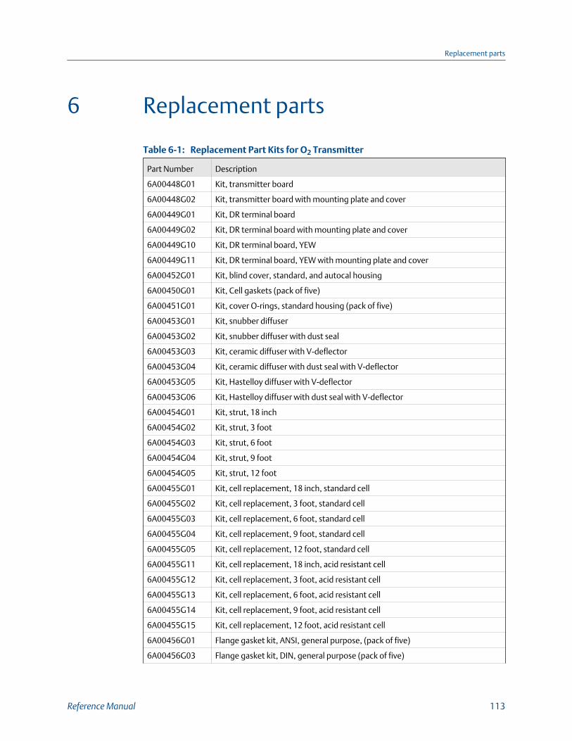
6 Replacement parts
Replacement Part Kits for O2 TransmitterTable 6-1:
Part Number Description
6A00448G01 Kit, transmitter board
6A00448G02 Kit, transmitter board with mounting plate and cover
6A00449G01 Kit, DR terminal board
6A00449G02 Kit, DR terminal board with mounting plate and cover
6A00449G10 Kit, DR terminal board, YEW
6A00449G11 Kit, DR terminal board, YEW with mounting plate and cover
6A00452G01 Kit, blind cover, standard, and autocal housing
6A00450G01 Kit, Cell gaskets (pack of five)
6A00451G01 Kit, cover O-rings, standard housing (pack of five)
6A00453G01 Kit, snubber diffuser
6A00453G02 Kit, snubber diffuser with dust seal
6A00453G03 Kit, ceramic diffuser with V-deflector
6A00453G04 Kit, ceramic diffuser with dust seal with V-deflector
6A00453G05 Kit, Hastelloy diffuser with V-deflector
6A00453G06 Kit, Hastelloy diffuser with dust seal with V-deflector
6A00454G01 Kit, strut, 18 inch
6A00454G02 Kit, strut, 3 foot
6A00454G03 Kit, strut, 6 foot
6A00454G04 Kit, strut, 9 foot
6A00454G05 Kit, strut, 12 foot
6A00455G01 Kit, cell replacement, 18 inch, standard cell
6A00455G02 Kit, cell replacement, 3 foot, standard cell
6A00455G03 Kit, cell replacement, 6 foot, standard cell
6A00455G04 Kit, cell replacement, 9 foot, standard cell
6A00455G05 Kit, cell replacement, 12 foot, standard cell
6A00455G11 Kit, cell replacement, 18 inch, acid resistant cell
6A00455G12 Kit, cell replacement, 3 foot, acid resistant cell
6A00455G13 Kit, cell replacement, 6 foot, acid resistant cell
6A00455G14 Kit, cell replacement, 9 foot, acid resistant cell
6A00455G15 Kit, cell replacement, 12 foot, acid resistant cell
6A00456G01 Flange gasket kit, ANSI, general purpose, (pack of five)
6A00456G03 Flange gasket kit, DIN, general purpose (pack of five)
Replacement parts
Reference Manual 113
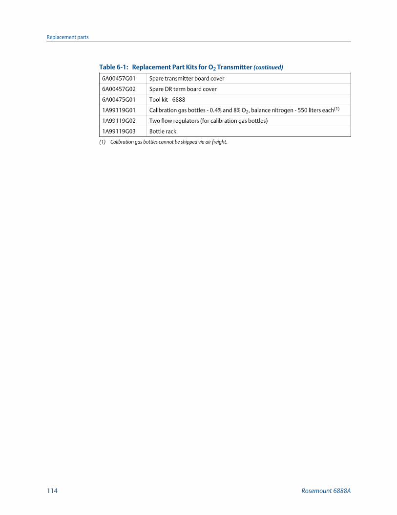
Replacement Part Kits for O2 Transmitter (continued)Table 6-1:
6A00457G01 Spare transmitter board cover
6A00457G02 Spare DR term board cover
6A00475G01 Tool kit - 6888
1A99119G01 Calibration gas bottles - 0.4% and 8% O2, balance nitrogen - 550 liters each(1)
1A99119G02 Two flow regulators (for calibration gas bottles)
1A99119G03 Bottle rack
(1) Calibration gas bottles cannot be shipped via air freight.
Replacement parts
114 Rosemount 6888A
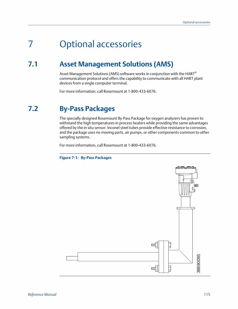
7 Optional accessories
7.1 Asset Management Solutions (AMS)Asset Management Solutions (AMS) software works in conjunction with the HART®
communication protocol and offers the capability to communicate with all HART plantdevices from a single computer terminal.
For more information, call Rosemount at 1-800-433-6076.
7.2 By-Pass PackagesThe specially designed Rosemount By-Pass Package for oxygen analyzers has proven towithstand the high temperatures in process heaters while providing the same advantagesoffered by the in situ sensor. Inconel steel tubes provide effective resistance to corrosion,and the package uses no moving parts, air pumps, or other components common to othersampling systems.
For more information, call Rosemount at 1-800-433-6076.
By-Pass PackagesFigure 7-1:
Optional accessories
Reference Manual 115
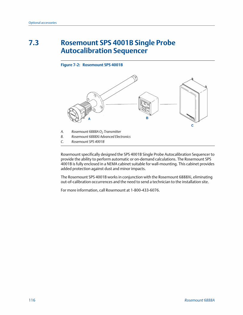
7.3 Rosemount SPS 4001B Single ProbeAutocalibration Sequencer
Rosemount SPS 4001BFigure 7-2:
A. Rosemount 6888A O2 TransmitterB. Rosemount 6888Xi Advanced ElectronicsC. Rosemount SPS 4001B
Rosemount specifically designed the SPS 4001B Single Probe Autocalibration Sequencer toprovide the ability to perform automatic or on-demand calculations. The Rosemount SPS4001B is fully enclosed in a NEMA cabinet suitable for wall-mounting. This cabinet providesadded protection against dust and minor impacts.
The Rosemount SPS 4001B works in conjunction with the Rosemount 6888Xi, eliminatingout-of-calibration occurrences and the need to send a technician to the installation site.
For more information, call Rosemount at 1-800-433-6076.
Optional accessories
116 Rosemount 6888A
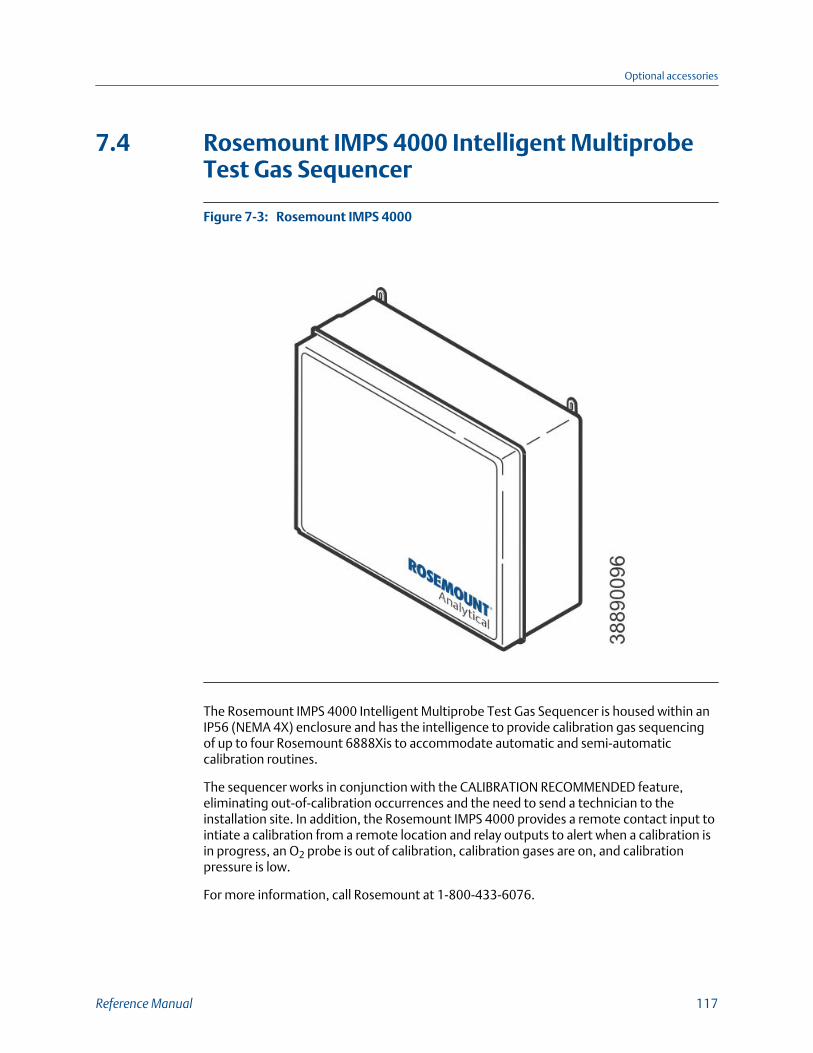
7.4 Rosemount IMPS 4000 Intelligent MultiprobeTest Gas Sequencer
Rosemount IMPS 4000Figure 7-3:
The Rosemount IMPS 4000 Intelligent Multiprobe Test Gas Sequencer is housed within anIP56 (NEMA 4X) enclosure and has the intelligence to provide calibration gas sequencingof up to four Rosemount 6888Xis to accommodate automatic and semi-automaticcalibration routines.
The sequencer works in conjunction with the CALIBRATION RECOMMENDED feature,eliminating out-of-calibration occurrences and the need to send a technician to theinstallation site. In addition, the Rosemount IMPS 4000 provides a remote contact input tointiate a calibration from a remote location and relay outputs to alert when a calibration isin progress, an O2 probe is out of calibration, calibration gases are on, and calibrationpressure is low.
For more information, call Rosemount at 1-800-433-6076.
Optional accessories
Reference Manual 117
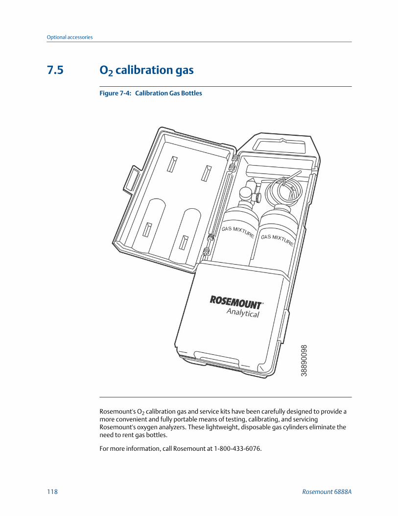
7.5 O2 calibration gas
Calibration Gas BottlesFigure 7-4:
Rosemount's O2 calibration gas and service kits have been carefully designed to provide amore convenient and fully portable means of testing, calibrating, and servicingRosemount's oxygen analyzers. These lightweight, disposable gas cylinders eliminate theneed to rent gas bottles.
For more information, call Rosemount at 1-800-433-6076.
Optional accessories
118 Rosemount 6888A

7.6 Optional Rosemount OxyBalance Display andAveraging SystemThe optional Rosemount OxyBalance Display and Averaging System receives up to eight4-20 mA signals from individual probes, trends individual outputs, and calculates fourprogrammable averages as additional 4-20 mA outputs. For more information, callRosemount at 1-800-433-6076.
Rosemount OxyBalance SystemFigure 7-5:
Optional accessories
Reference Manual 119

Optional accessories
120 Rosemount 6888A
Appendix ARosemount™ 6888 product certifications
A.1 European Directive informationA copy of the EC Declaration of Conformity can be found at the end of the Quick StartGuide. The most recent revision of the EC Declaration of Conformity can be found at Emerson.com/Rosemount.
A.2 Ordinary location certificationAs standard, the transmitter has been examined and tested to determine that the designmeets the basic electrical, mechanical, and fire protection requirements by a nationallyrecognized test laboratory (NRTL) as accredited by the Federal Occupational Safety andHealth Administration (OSHA).
A.3 Installing equipment in North AmericaThe US National Electrical Code (NEC) and the Canadian Electrical Code (CEC) permit theuse of Division marked equipment in Zones and Zone marked equipment in Divisions. Themarking must be suitable for the area classification, gas, and temperature class. Thisinformation is clearly defined in the respective codes.
A.4 Rosemount™ 6888A In-Situ Oxygen Transmitterfor General Purpose Locations
A.4.1 USA
FM Certificate FM17NUS0009X
Standards FM 3810:2005, ANSI/IEC-250:2003, ANSI/EC 60529:2004
Markings Type 4X, IP66
Special conditions for use
1. Type 4X and IP66 applies to the transmitter portion that is mounted externally tothe flue duct.
Rosemount™
6888 product certifications
Reference Manual 121
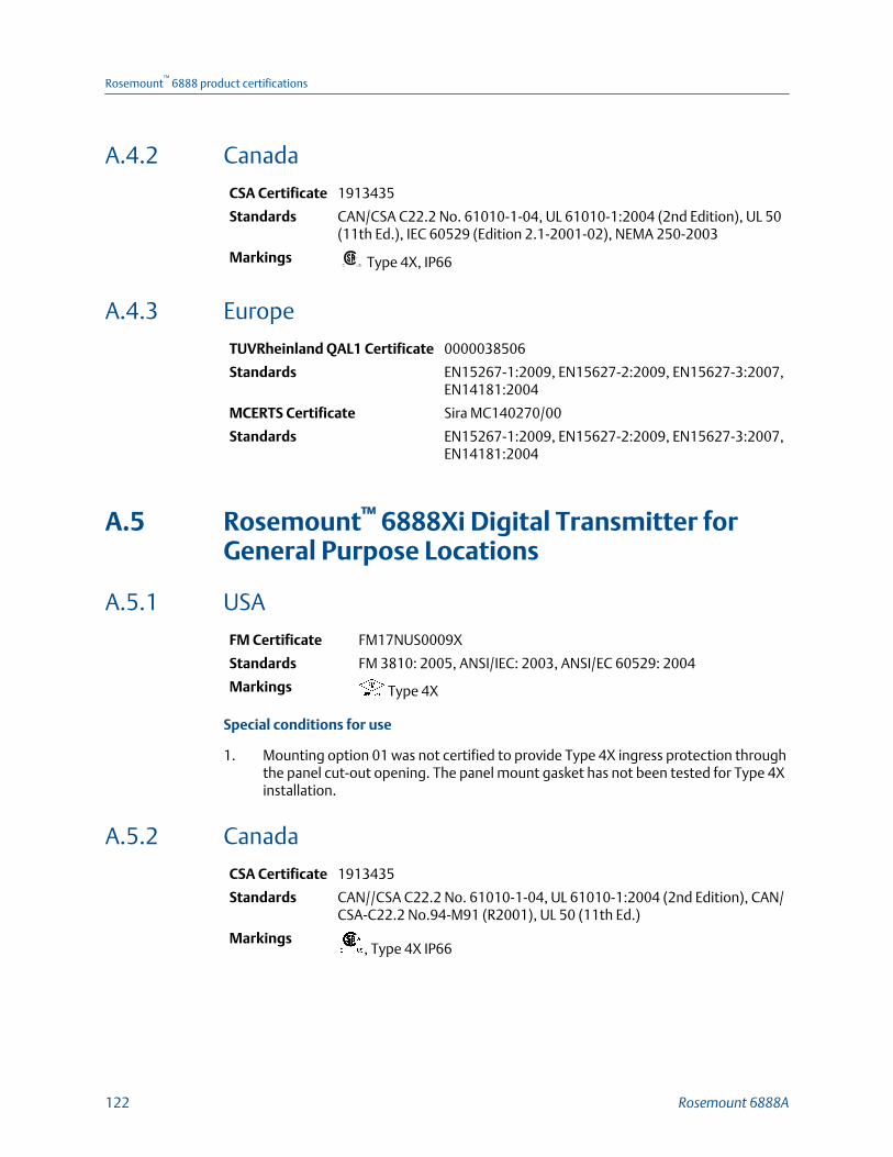
A.4.2 Canada
CSA Certificate 1913435
Standards CAN/CSA C22.2 No. 61010-1-04, UL 61010-1:2004 (2nd Edition), UL 50(11th Ed.), IEC 60529 (Edition 2.1-2001-02), NEMA 250-2003
Markings Type 4X, IP66
A.4.3 Europe
TUVRheinland QAL1 Certificate 0000038506
Standards EN15267-1:2009, EN15627-2:2009, EN15627-3:2007,EN14181:2004
MCERTS Certificate Sira MC140270/00
Standards EN15267-1:2009, EN15627-2:2009, EN15627-3:2007,EN14181:2004
A.5 Rosemount™ 6888Xi Digital Transmitter forGeneral Purpose Locations
A.5.1 USA
FM Certificate FM17NUS0009X
Standards FM 3810: 2005, ANSI/IEC: 2003, ANSI/EC 60529: 2004
Markings Type 4X
Special conditions for use
1. Mounting option 01 was not certified to provide Type 4X ingress protection throughthe panel cut-out opening. The panel mount gasket has not been tested for Type 4Xinstallation.
A.5.2 Canada
CSA Certificate 1913435
Standards CAN//CSA C22.2 No. 61010-1-04, UL 61010-1:2004 (2nd Edition), CAN/CSA-C22.2 No.94-M91 (R2001), UL 50 (11th Ed.)
Markings, Type 4X IP66
Rosemount™
6888 product certifications
122 Rosemount 6888A
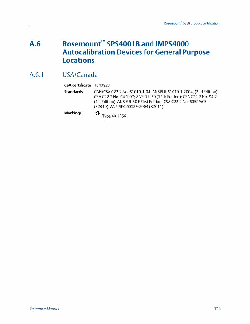
A.6 Rosemount™ SPS4001B and IMPS4000Autocalibration Devices for General PurposeLocations
A.6.1 USA/Canada
CSA certificate 1640823
Standards CAN/CSA C22.2 No. 61010-1-04; ANSI/UL 61010-1:2004, (2nd Edition);CSA C22.2 No. 94.1-07; ANSI/UL 50 (12th Edition); CSA C22.2 No. 94.2(1st Edition); ANSI/UL 50 E First Edition; CSA C22.2 No. 60529:05(R2010); ANSI/IEC 60529-2004 (R2011)
Markings Type 4X, IP66
Rosemount™
6888 product certifications
Reference Manual 123

Rosemount™
6888 product certifications
124 Rosemount 6888A
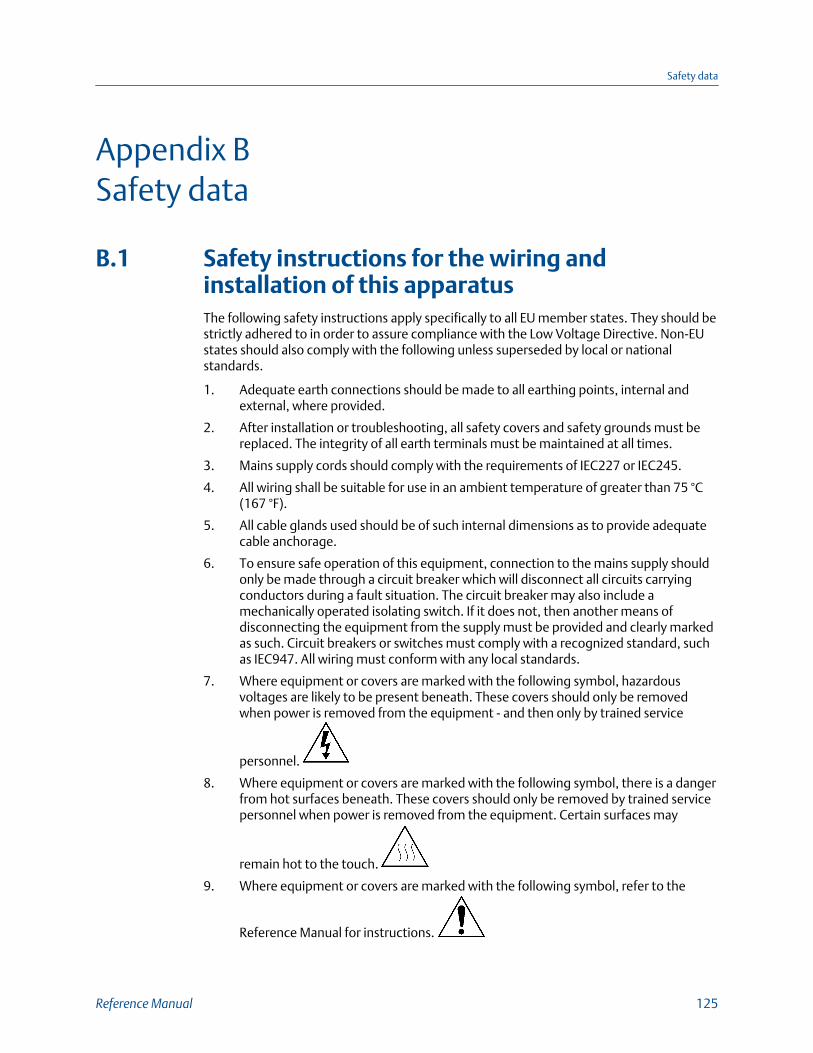
Appendix BSafety data
B.1 Safety instructions for the wiring andinstallation of this apparatusThe following safety instructions apply specifically to all EU member states. They should bestrictly adhered to in order to assure compliance with the Low Voltage Directive. Non-EUstates should also comply with the following unless superseded by local or nationalstandards.
1. Adequate earth connections should be made to all earthing points, internal andexternal, where provided.
2. After installation or troubleshooting, all safety covers and safety grounds must bereplaced. The integrity of all earth terminals must be maintained at all times.
3. Mains supply cords should comply with the requirements of IEC227 or IEC245.
4. All wiring shall be suitable for use in an ambient temperature of greater than 75 °C(167 °F).
5. All cable glands used should be of such internal dimensions as to provide adequatecable anchorage.
6. To ensure safe operation of this equipment, connection to the mains supply shouldonly be made through a circuit breaker which will disconnect all circuits carryingconductors during a fault situation. The circuit breaker may also include amechanically operated isolating switch. If it does not, then another means ofdisconnecting the equipment from the supply must be provided and clearly markedas such. Circuit breakers or switches must comply with a recognized standard, suchas IEC947. All wiring must conform with any local standards.
7. Where equipment or covers are marked with the following symbol, hazardousvoltages are likely to be present beneath. These covers should only be removedwhen power is removed from the equipment - and then only by trained service
personnel.
8. Where equipment or covers are marked with the following symbol, there is a dangerfrom hot surfaces beneath. These covers should only be removed by trained servicepersonnel when power is removed from the equipment. Certain surfaces may
remain hot to the touch.
9. Where equipment or covers are marked with the following symbol, refer to the
Reference Manual for instructions.
Safety data
Reference Manual 125
10. All graphical symbols used in this product are from one or more of the followingstandards: EN61010-1, IEC417, and ISO3864.
11. Where equipment or labels are marked "Do Not Open While Energized" or similar,there is a danger of ignition in areas where an explosive atmosphere is present. Thisequipment should only be opened when the power is removed and adequate timeas specified in the label or in the intruction manual has been allowed for theequipment to cool down - and then only by trained service personnel.
Safety data
126 Rosemount 6888A

Safety data
Reference Manual 127
00809-0100-4890
Rev AA
2018
GLOBAL HEADQUARTERSEmerson Automation Solutions6021 Innovation BlvdShakopee, MN 55379, USA
+1 800 999 9307 or +1 952 906 8888
+1 952 949 7001
NORTH AMERICARosemount8200 Market BoulevardChanhassen, MN 55317
+1 800 999 9307
+1 952 949 7001
EUROPEEmerson Automation SolutionsNeuhofstrasse 19a P.O. Box 1046CH-6340 BaarSwitzerland
+ 41 (0) 41 768 6111
+ 41 (0) 41 768 6300
MIDDLE EAST AND AFRICAEmerson Automation SolutionsEmerson FZEJebel Ali Free ZoneDubai, United Arab Emirates, P.O. Box 17033
+971 4 811 8100
+971 4 886 5465
ASIA-PACIFICEmerson Automation Solutions1 Pandan CrescentSingapore 128461Singapore
+65 777 8211
+65 777 0947
Linkedin.com/company/Emerson-Automation-Solutions
twitter.com/rosemount_news
Facebook.com/Rosemount
youtube.com/RosemountMeasurement
google.com/+RosemountMeasurement
AnalyticExpert.com
©2018 Emerson. All rights reserved.
The Emerson logo is a trademark and service mark of Emerson Electric Co. Rosemount is amark of one of the Emerson family of companies. All other marks are the property of theirrespective owners.