Manual reparacion Jeep Compass - Patriot Limited 2007-2009_Emission control
48
2009 ENGINE PERFORMANCE Emissions Control - Compass & Patriot DESCRIPTION MONITORED COMPONENT There are several components that will affect vehicle emissions if they malfunction. If one of these components malfunctions the Malfunction Indicator Lamp (Check Engine) will illuminate. Some of the component monitors are checking for proper operation of the part. Electrically operated components now have input (rationality) and output (functionality) checks as well as continuity tests (opens/shorts). Previously, a component like the Throttle Position sensor (TPS) was checked by the PCM for an open or shorted circuit. If one of these conditions occurred, a DTC was set. Now there is a check to ensure that the component is working. This is done by watching for a TPS indication of a greater or lesser throttle opening than MAP and engine RPM indicate. In the case of the TPS, if engine vacuum is high and engine RPM is 1600 or greater and the TPS indicates a large throttle opening, a DTC will be set. The same applies to low vacuum and 1600 RPM. Any component that has an associated 'limp in' will set a fault after 1 trip with the malfunction present. Refer to DIAGNOSTIC CODE INDEX (GAS) or DIAGNOSTIC CODE INDEX (DIESEL) for diagnostic procedures. The following is a list of the monitored components: z Catalyst Monitor z Comprehensive Components z EGR (if equipped) z Fuel Control (rich/lean) z Oxygen Sensor Monitor z Oxygen Sensor Heater Monitor z Purge z Misfire z Evaporative System Integrity Monitor (ESIM) COMPREHENSIVE COMPONENTS Along with the major monitors, OBD II requires that the diagnostic system monitor any component that could affect emissions levels. In many cases, these components were being tested under OBD I. The OBD I requirements focused mainly on testing emissions-related components for electrical opens and shorts. However, OBD II also requires that inputs from powertrain components to the PCM be tested for rationality , and that outputs to powertrain components from the PCM be tested for functionality . Methods for monitoring 2009 Jeep Patriot Limited 2009 ENGINE PERFORMANCE Emissions Control - Compass & Patriot
-
Upload
gustavo-castro -
Category
Automotive
-
view
45 -
download
8
Transcript of Manual reparacion Jeep Compass - Patriot Limited 2007-2009_Emission control

2009 ENGINE PERFORMANCE
Emissions Control - Compass & Patriot
DESCRIPTION
MONITORED COMPONENT
There are several components that will affect vehicle emissions if they malfunction. If one of these components malfunctions the Malfunction Indicator Lamp (Check Engine) will illuminate.
Some of the component monitors are checking for proper operation of the part. Electrically operated components now have input (rationality) and output (functionality) checks as well as continuity tests (opens/shorts). Previously, a component like the Throttle Position sensor (TPS) was checked by the PCM for an open or shorted circuit. If one of these conditions occurred, a DTC was set. Now there is a check to ensure that the component is working. This is done by watching for a TPS indication of a greater or lesser throttle opening than MAP and engine RPM indicate. In the case of the TPS, if engine vacuum is high and engine RPM is 1600 or greater and the TPS indicates a large throttle opening, a DTC will be set. The same applies to low vacuum and 1600 RPM.
Any component that has an associated 'limp in' will set a fault after 1 trip with the malfunction present.
Refer to DIAGNOSTIC CODE INDEX (GAS) or DIAGNOSTIC CODE INDEX (DIESEL) for diagnostic procedures.
The following is a list of the monitored components:
Catalyst Monitor Comprehensive Components EGR (if equipped) Fuel Control (rich/lean) Oxygen Sensor Monitor Oxygen Sensor Heater Monitor Purge Misfire Evaporative System Integrity Monitor (ESIM)
COMPREHENSIVE COMPONENTS
Along with the major monitors, OBD II requires that the diagnostic system monitor any component that could affect emissions levels. In many cases, these components were being tested under OBD I. The OBD I requirements focused mainly on testing emissions-related components for electrical opens and shorts.
However, OBD II also requires that inputs from powertrain components to the PCM be tested for rationality , and that outputs to powertrain components from the PCM be tested for functionality . Methods for monitoring
2009 Jeep Patriot Limited2009 ENGINE PERFORMANCE Emissions Control - Compass & Patriot
2009 Jeep Patriot Limited2009 ENGINE PERFORMANCE Emissions Control - Compass & Patriot
a
Saturday, September 08, 2012 1:31:39 PM Page 1 © 2006 Mitchell Repair Information Company, LLC.
a
Saturday, September 08, 2012 1:31:43 PM Page 1 © 2006 Mitchell Repair Information Company, LLC.

the various Comprehensive Component monitoring include:
1. Circuit Continuity Open Shorted high Shorted to ground
2. Rationality or Proper Functioning
Inputs tested for rationality Outputs tested for functionality
Input Rationality - While input signals to the PCM are constantly being monitored for electrical opens and shorts, they are also tested for rationality. This means that the input signal is compared against other inputs and information to see if it makes sense under the current conditions.
PCM sensor inputs that are checked for rationality include:
Manifold Absolute Pressure (MAP) Sensor Oxygen Sensor (O2S) (slow response) Engine Coolant Temperature (ECT) Sensor Camshaft Position (CMP) Sensor Vehicle Speed Sensor Crankshaft Position (CKP) Sensor Inlet Air Temperature Sensor Throttle Position (TPS) Sensor Power Steering Switch Oxygen Sensor Heater Engine Controller Brake Switch Evaporative System Integrity Monitor (ESIM) P/N Switch Trans Controls
Output Functionality - PCM outputs are tested for functionality in addition to testing for opens and shorts. When the PCM provides a voltage to an output component, it can verify that the command was carried out by monitoring specific input signals for expected changes. For example, when the PCM commands the Idle Air Control (IAC) Motor to a specific position under certain operating conditions, it expects to see a specific (target) idle speed (RPM). If it does not, it stores a DTC.
NOTE: Comprehensive component monitors are continuous. Therefore, enabling conditions do not apply. All will set a DTC and illuminate the MIL in 1- trip.
2009 Jeep Patriot Limited2009 ENGINE PERFORMANCE Emissions Control - Compass & Patriot
a
Saturday, September 08, 2012 1:31:40 PM Page 2 © 2006 Mitchell Repair Information Company, LLC.

PCM outputs monitored for functionality include:
Fuel Injectors Ignition Coils Torque Converter Clutch Solenoid Purge Solenoid EGR Solenoid (if equipped) Radiator Fan Control Trans Controls
OXYGEN SENSOR (O2S) MONITOR
DESCRIPTION - Effective control of exhaust emissions is achieved by an oxygen feedback system. The most important element of the feedback system is the O2S. The O2S is located in the exhaust path. Once it reaches operating temperature 300° to 350°C (572° to 662°F), the sensor generates a voltage that is inversely proportional to the amount of oxygen in the exhaust. When there is a large amount of oxygen in the exhaust caused by a lean condition, misfire or exhaust leak, the sensor produces a low voltage, below 450 mV. When the oxygen content is lower, caused by a rich condition, the sensor produces a higher voltage, above 450mV.
The information obtained by the sensor is used to calculate the fuel injector pulse width. The PCM is programmed to maintain the optimum air/fuel ratio. At this mixture ratio, the catalyst works best to remove hydrocarbons (HC), carbon monoxide (CO) and nitrous oxide (NOx) from the exhaust.
The O2S is also the main sensing element for the EGR, Catalyst and Fuel Monitors, and purge.
The O2S may fail in any or all of the following manners:
Slow response rate (Big Slope) Reduced output voltage (Half Cycle) Heater Performance
Slow Response Rate (Big Slope) - Response rate is the time required for the sensor to switch from lean to rich signal output once it is exposed to a richer than optimum A/F mixture or vice versa. As the PCM adjusts the air/fuel ratio, the sensor must be able to rapidly detect the change. As the sensor ages, it could take longer to detect the changes in the oxygen content of the exhaust gas. The rate of change that an oxygen sensor experiences is called 'Big Slope'. The PCM checks the oxygen sensor voltage in increments of a few milliseconds.
Reduced Output Voltage (Half Cycle) - The output voltage of the O2S ranges from 2.5 to 5 volt. A good sensor can easily generate any output voltage in this range as it is exposed to different concentrations of oxygen. To detect a shift in the A/F mixture (lean or rich), the output voltage has to change beyond a threshold value. A malfunctioning sensor could have difficulty changing beyond the threshold value. Many times the condition is only temporary and the sensor will recover. Under normal conditions the voltage signal surpasses the threshold, and a counter is incremented by one. This is called the Half Cycle Counter.
2009 Jeep Patriot Limited2009 ENGINE PERFORMANCE Emissions Control - Compass & Patriot
a
Saturday, September 08, 2012 1:31:40 PM Page 3 © 2006 Mitchell Repair Information Company, LLC.

Heater Performance - The heater is tested by a separate monitor. Refer to OXYGEN SENSOR HEATER MONITOR.
OPERATION - As the Oxygen Sensor signal switches, the PCM monitors the half cycle and big slope signals from the oxygen sensor. If during the test neither counter reaches a predetermined value, a malfunction is entered and a Freeze Frame is stored. Only one counter reaching its predetermined value is needed for the monitor to pass.
The Oxygen Sensor Signal Monitor is a two trip monitor that is tested only once per trip. When the Oxygen Sensor fails the test in two consecutive trips, the MIL is illuminated and a DTC is set. The MIL is extinguished when the Oxygen Sensor monitor passes in three consecutive trips. The DTC is erased from memory after 40 consecutive warm-up cycles without test failure.
Enabling Conditions - The following conditions must typically be met for the PCM to run the oxygen sensor monitor:
Battery voltage Engine temperature Engine run time Engine run time at a predetermined speed Engine run time at a predetermined speed and throttle opening Transmission in gear (automatic only) Fuel system in Closed Loop Long Term Adaptive (within parameters) Power Steering Switch in low PSI (no load) Engine at idle Fuel level above 15% Barometric pressure Engine RPM within acceptable range of desired idle Closed throttle speed
Pending Conditions - The Task Manager typically does not run the Oxygen Sensor Signal Monitor if overlapping monitors are running or the MIL is illuminated for any of the following:
Misfire Monitor Front Oxygen Sensor and Heater Monitor MAP Sensor Vehicle Speed Sensor Engine Coolant Temperature Sensor Throttle Position Engine Controller Self Test Faults Cam or Crank Sensor
2009 Jeep Patriot Limited2009 ENGINE PERFORMANCE Emissions Control - Compass & Patriot
a
Saturday, September 08, 2012 1:31:40 PM Page 4 © 2006 Mitchell Repair Information Company, LLC.

Injector and Coil EVAP Electrical EGR Solenoid Electrical (if equipped) Intake Air Temperature 5 Volt Feed
Conflict - The Task Manager does not run the Oxygen Sensor Monitor if any of the following conditions are present:
A/C ON (A/C clutch cycling temporarily suspends monitor) Purge flow in progress
Suspend - The Task Manager suspends maturing a fault for the Oxygen Sensor Monitor if any of the following are present:
Oxygen Sensor Heater Monitor, Priority 1 Misfire Monitor, Priority 2
CATALYST MONITOR
To comply with clean air regulations, vehicles are equipped with catalytic converters. These converters reduce the emission of hydrocarbons, oxides of nitrogen and carbon monoxide.
Normal vehicle miles or engine misfire can cause a catalyst to decay. A meltdown of the ceramic core can cause a reduction of the exhaust passage. This can increase vehicle emissions and deteriorate engine performance, driveability and fuel economy.
The catalyst monitor uses dual oxygen sensors (O2S's) to monitor the efficiency of the converter. The dual O2S strategy is based on the fact that as a catalyst deteriorates, its oxygen storage capacity and its efficiency are both reduced. By monitoring the oxygen storage capacity of a catalyst, its efficiency can be indirectly calculated. The upstream O2S is used to detect the amount of oxygen in the exhaust gas before the gas enters the catalytic converter. The PCM calculates the A/F mixture from the output of the O2S. A low voltage indicates high oxygen content (lean mixture). A high voltage indicates a low content of oxygen (rich mixture).
When the upstream O2S detects a high oxygen condition, there is an abundance of oxygen in the exhaust gas. A functioning converter would store this oxygen so it can use it for the oxidation of HC and CO. As the converter absorbs the oxygen, there will be a lack of oxygen downstream of the converter. The output of the downstream O2S will indicate limited activity in this condition.
As the converter loses the ability to store oxygen, the condition can be detected from the behavior of the downstream O2S. When the efficiency drops, no chemical reaction takes place. This means the concentration of oxygen will be the same downstream as upstream. The output voltage of the downstream O2S copies the voltage of the upstream sensor. The only difference is a time lag (seen by the PCM) between the switching of the O2S's.
2009 Jeep Patriot Limited2009 ENGINE PERFORMANCE Emissions Control - Compass & Patriot
a
Saturday, September 08, 2012 1:31:40 PM Page 5 © 2006 Mitchell Repair Information Company, LLC.

To monitor the system, the number of lean-to-rich switches of upstream and downstream O2S's is counted. The ratio of downstream switches to upstream switches is used to determine whether the catalyst is operating properly. An effective catalyst will have fewer downstream switches than it has upstream switches i.e., a ratio closer to zero. For a totally ineffective catalyst, this ratio will be one-to-one, indicating that no oxidation occurs in the device.
The system must be monitored so that when catalyst efficiency deteriorates and exhaust emissions increase to over the legal limit, the MIL (check engine lamp) will be illuminated.
Monitor Operation - To monitor catalyst efficiency, the PCM expands the rich and lean switch points of the heated oxygen sensor. With extended switch points, the air/fuel mixture runs richer and leaner to overburden the catalytic converter. Once the test is started, the air/fuel mixture runs rich and lean and the O2 switches are counted. A switch is counted when an oxygen sensor signal goes from below the lean threshold to above the rich threshold. The number of Rear O2 sensor switches is divided by the number of Front O2 sensor switches to determine the switching ratio.
The test runs for 20 seconds. As catalyst efficiency deteriorates over the life of the vehicle, the switch rate at the downstream sensor approaches that of the upstream sensor. If at any point during the test period the switch ratio reaches a predetermined value, a counter is incremented by one. The monitor is enabled to run another test during that trip. When the test fails three times, the counter increments to three, a malfunction is entered, and a Freeze Frame is stored. When the counter increments to three during the next trip, the code is matured and the MIL is illuminated. If the test passes the first, no further testing is conducted during that trip.
The MIL is extinguished after three consecutive good trips. The good trip criteria for the catalyst monitor is more stringent than the failure criteria. In order to pass the test and increment one good trip, the downstream sensor switch rate must be less than 80% of the upstream rate (60% for manual transmissions). The failure percentages are 90% and 70% respectively.
Enabling Conditions - The following conditions must typically be met before the PCM runs the catalyst monitor. Specific times for each parameter may be different from engine to engine.
Accumulated drive time Enable time Ambient air temperature Barometric pressure Catalyst warm-up counter Engine coolant temperature Accumulated throttle position sensor Vehicle speed MAP RPM Engine in closed loop Fuel level
2009 Jeep Patriot Limited2009 ENGINE PERFORMANCE Emissions Control - Compass & Patriot
a
Saturday, September 08, 2012 1:31:40 PM Page 6 © 2006 Mitchell Repair Information Company, LLC.

Pending Conditions -
Misfire DTC Front Oxygen Sensor Response Front Oxygen Sensor Heater Monitor Front Oxygen Sensor Electrical Rear Oxygen Sensor Rationality (middle check) Rear Oxygen Sensor Heater Monitor Rear Oxygen Sensor Electrical Fuel System Monitor All MAP faults All ECT sensor faults Purge flow solenoid functionality Purge flow solenoid electrical All PCM self test faults All CMP and CKP sensor faults All injector and ignition electrical faults Vehicle Speed Sensor Brake switch Inlet air temperature
Conflict - The catalyst monitor does not run if any of the following are conditions are present:
EGR Monitor in progress Fuel system rich intrusive test in progress EVAP Monitor in progress Time since start is less than 60 seconds Low fuel level Low ambient air temperature
Suspend - The Task Manager does not mature a catalyst fault if any of the following are present:
Oxygen Sensor Monitor, Priority 1 Upstream Oxygen Sensor Heater, Priority 1 EGR Monitor, Priority 1 EVAP Monitor, Priority 1 Fuel System Monitor, Priority 2 Misfire Monitor, Priority 2
VEHICLE EMISSION CONTROL INFORMATION LABEL
2009 Jeep Patriot Limited2009 ENGINE PERFORMANCE Emissions Control - Compass & Patriot
a
Saturday, September 08, 2012 1:31:40 PM Page 7 © 2006 Mitchell Repair Information Company, LLC.

All models have a Vehicle Emission Control Information (VECI) Label. Chrysler permanently attaches the label in the engine compartment. It cannot be removed without defacing information and destroying the label.
The label contains the vehicle's model year and what regulations the vehicle conforms to also if the vehicle is OBD II compliant.
TRIP DEFINITION
A "Trip" means vehicle operation (following an engine-off period) of duration and driving mode such that all components and systems are monitored at least once by the diagnostic system. The monitors must successfully pass before the PCM can verify that a previously malfunctioning component is meeting the normal operating conditions of that component. For misfire or fuel system malfunction, the MIL may be extinguished if the fault does not recur when monitored during three subsequent sequential driving cycles in which conditions are similar to those under which the malfunction was first determined.
Anytime the MIL is illuminated, a DTC is stored. The DTC can self erase only after the MIL has been extinguished. Once the MIL is extinguished, the PCM must pass the diagnostic test for the most recent DTC for 40 warm-up cycles (80 warm-up cycles for the Fuel System Monitor and the Misfire Monitor). A warm-up cycle can best be described by the following:
The engine must be running A rise of 4.4° C (40°F) in engine temperature must occur from the time when the engine was started Engine coolant temperature must crossover 71° C (160°F) A "driving cycle" that consists of engine start up and engine shut off.
Once the above conditions occur, the PCM is considered to have passed a warm-up cycle. Due to the conditions required to extinguish the MIL and erase the DTC, it is most important that after a repair has been made, all DTC's be erased and the repair verified by running 1-good trip.
NON-MONITORED CIRCUITS
The PCM does not monitor all circuits, systems and conditions that could have malfunctions causing driveability problems. However, problems with these systems may cause the PCM to store diagnostic trouble codes for other systems or components. For example, a fuel pressure problem will not register a fault directly, but could cause a rich/lean condition or misfire. This could cause the PCM to store an oxygen sensor or misfire diagnostic trouble code.
The major non-monitored circuits are listed below along with examples of failures modes that do not directly cause the PCM to set a DTC, but for a system that is monitored.
FUEL PRESSURE
The fuel pressure regulator controls fuel system pressure. The PCM cannot detect a clogged fuel pump inlet filter or a pinched fuel supply. However, these could result in a rich or lean condition causing the PCM to store an oxygen sensor, fuel system, or misfire diagnostic trouble code.
2009 Jeep Patriot Limited2009 ENGINE PERFORMANCE Emissions Control - Compass & Patriot
a
Saturday, September 08, 2012 1:31:40 PM Page 8 © 2006 Mitchell Repair Information Company, LLC.

SECONDARY IGNITION CIRCUIT
The PCM cannot detect an inoperative ignition coil, fouled or worn spark plugs, ignition cross firing, or open spark plug cables. The misfire will however, increase the oxygen content in the exhaust, deceiving the PCM in to thinking the fuel system is too lean. Also see misfire detection. There are DTC's that can detect misfire and Ionization shorts in the secondary ignition circuit, refer to DIAGNOSTIC CODE INDEX (GAS) .
CYLINDER COMPRESSION
The PCM cannot detect uneven, low, or high engine cylinder compression. Low compression lowers O2 content in the exhaust. Leading to fuel system, oxygen sensor, or misfire detection fault.
EXHAUST SYSTEM
The PCM cannot detect a plugged, restricted or leaking exhaust system. It may set a EGR (if equipped) or Fuel system or O2S fault.
FUEL INJECTOR MECHANICAL MALFUNCTIONS
The PCM cannot determine if a fuel injector is clogged, the needle is sticking or if the wrong injector is installed. However, these could result in a rich or lean condition causing the PCM to store a diagnostic trouble code for either misfire, an oxygen sensor, or the fuel system.
EXCESSIVE OIL CONSUMPTION
Although the PCM monitors engine exhaust oxygen content when the system is in closed loop, it cannot determine excessive oil consumption.
THROTTLE BODY AIR FLOW
The PCM cannot detect a clogged or restricted air cleaner inlet or filter element.
VACUUM ASSIST
The PCM cannot detect leaks or restrictions in the vacuum circuits of vacuum assisted engine control system devices. However, these could cause the PCM to store a MAP sensor diagnostic trouble code and cause a high idle condition.
PCM SYSTEM GROUND
The PCM cannot determine a poor system ground. However, one or more diagnostic trouble codes may be generated as a result of this condition. The module should be mounted to the body at all times, including when diagnostics are performed.
PCM CONNECTOR ENGAGEMENT
The PCM may not be able to determine spread or damaged connector pins. However, it might store diagnostic trouble codes as a result of spread connector pins.
2009 Jeep Patriot Limited2009 ENGINE PERFORMANCE Emissions Control - Compass & Patriot
a
Saturday, September 08, 2012 1:31:40 PM Page 9 © 2006 Mitchell Repair Information Company, LLC.

MONITORED SYSTEMS
There are new electronic circuit monitors that check fuel, emission, engine and ignition performance. These monitors use information from various sensor circuits to indicate the overall operation of the fuel, engine, ignition and emission systems and thus the emissions performance of the vehicle.
The fuel, engine, ignition and emission systems monitors do not indicate a specific component problem. They do indicate that there is an implied problem within one of the systems and that a specific problem must be diagnosed.
If any of these monitors detect a problem affecting vehicle emissions, the Malfunction Indicator (Check Engine) Lamp will be illuminated. These monitors generate Diagnostic Trouble Codes that can be displayed with the a scan tool.
The following is a list of the system monitors:
EGR Monitor (if equipped) Misfire Monitor Fuel System Monitor Oxygen Sensor Monitor Oxygen Sensor Heater Monitor Catalyst Monitor Evaporative System Leak Detection Monitor (if equipped)
Following is a description of each system monitor, and its DTC.
Refer to the appropriate Powertrain Diagnostics article for diagnostic procedures.
OXYGEN SENSOR (O2S) MONITOR
Effective control of exhaust emissions is achieved by an oxygen feedback system. The most important element of the feedback system is the O2S. The O2S is located in the exhaust path. Once it reaches operating temperatures of 300° to 350°C (572° to 662°F), the sensor generates a voltage that is inversely proportional to the amount of oxygen in the exhaust. The information obtained by the sensor is used to calculate the fuel injector pulse width. The PCM is programmed to maintain the optimum air/fuel ratio. At this mixture ratio, the catalyst works best to remove hydrocarbons (HC), carbon monoxide (CO) and nitrous oxide (NOx) from the exhaust.
The O2S is also the main sensing element for the EGR (if equipped), Catalyst and Fuel Monitors.
The O2S may fail in any or all of the following manners:
Slow response rate Reduced output voltage Dynamic shift
2009 Jeep Patriot Limited2009 ENGINE PERFORMANCE Emissions Control - Compass & Patriot
a
Saturday, September 08, 2012 1:31:40 PM Page 10 © 2006 Mitchell Repair Information Company, LLC.

Shorted or open circuits
Response rate is the time required for the sensor to switch from lean to rich once it is exposed to a richer than optimum A/F mixture or vice versa. As the sensor starts malfunctioning, it could take longer to detect the changes in the oxygen content of the exhaust gas.
The output voltage of the O2S ranges from 0 to 1 volt (voltages are offset by 2.5 volts on NGC vehicles). A good sensor can easily generate any output voltage in this range as it is exposed to different concentrations of oxygen. To detect a shift in the A/F mixture (lean or rich), the output voltage has to change beyond a threshold value. A malfunctioning sensor could have difficulty changing beyond the threshold value.
OXYGEN SENSOR HEATER MONITOR
If there is an oxygen sensor (O2S) DTC as well as a O2S heater DTC, the O2S heater fault MUST be repaired first. After the O2S fault is repaired, verify that the heater circuit is operating correctly.
Effective control of exhaust emissions is achieved by an oxygen feedback system. The most important element of the feedback system is the O2S. The O2S is located in the exhaust path. Once it reaches operating temperatures of 300-350°C (572-662°F), the sensor generates a voltage that is inversely proportional to the amount of oxygen in the exhaust. The information obtained by the sensor is used to calculate the fuel injector pulse width. This maintains a 14.7 to 1 Air Fuel (A/F) ratio. At this mixture ratio, the catalyst works best to remove hydrocarbons (HC), carbon monoxide (CO) and nitrogen oxide (NOx) from the exhaust.
The voltage readings taken from the O2S are very temperature sensitive. The readings are not accurate below 300°C (572°F). Heating of the O2S is done to allow the engine controller to shift to closed loop control as soon as possible. The heating element used to heat the O2S must be tested to ensure that it is heating the sensor properly.
The O2S circuit is monitored for a drop in voltage. The sensor output is used to test the heater by isolating the effect of the heater element on the O2S output voltage from the other effects.
EGR MONITOR (if equipped)
The Powertrain Control Module (PCM) performs an on-board diagnostic check of the EGR system.
The EGR monitor is used to test whether the EGR system is operating within specifications. The diagnostic check activates only during selected engine/driving conditions. When the conditions are met, the EGR is turned off (solenoid energized) and the O2S compensation control is monitored. Turning off the EGR shifts the air fuel (A/F) ratio in the lean direction. The O2S data should indicate an increase in the O2 concentration in the combustion chamber when the exhaust gases are no longer recirculated. While this test does not directly measure the operation of the EGR system, it can be inferred from the shift in the O2S data whether the EGR system is operating correctly. Because the O2S is being used, the O2S test must pass its test before the EGR test. Also looks at EGR linear potentiometer for feedback.
MISFIRE MONITOR
Excessive engine misfire results in increased catalyst temperature and causes an increase in HC emissions.
2009 Jeep Patriot Limited2009 ENGINE PERFORMANCE Emissions Control - Compass & Patriot
a
Saturday, September 08, 2012 1:31:40 PM Page 11 © 2006 Mitchell Repair Information Company, LLC.

Severe misfires could cause catalyst damage. To prevent catalytic convertor damage, the PCM monitors engine misfire.
The Powertrain Control Module (PCM) monitors for misfire during most engine operating conditions (positive torque) by looking at changes in the crankshaft speed. If a misfire occurs the speed of the crankshaft will vary more than normal.
FUEL SYSTEM MONITOR
To comply with clean air regulations, vehicles are equipped with catalytic converters. These converters reduce the emission of hydrocarbons, oxides of nitrogen and carbon monoxide. The catalyst works best when the air fuel (A/F) ratio is at or near the optimum of 14.7 to 1.
The PCM is programmed to maintain the optimum air/fuel ratio. This is done by making short term corrections in the fuel injector pulse width based on the O2S output. The programmed memory acts as a self calibration tool that the engine controller uses to compensate for variations in engine specifications, sensor tolerances and engine fatigue over the life span of the engine. By monitoring the actual air-fuel ratio with the O2S (short term) and multiplying that with the program long-term (adaptive) memory and comparing that to the limit, it can be determined whether it will pass an emissions test. If a malfunction occurs such that the PCM cannot maintain the optimum A/F ratio, then the MIL will be illuminated.
CATALYST MONITOR
To comply with clean air regulations, vehicles are equipped with catalytic converters. These converters reduce the emission of hydrocarbons, oxides of nitrogen and carbon monoxide.
Normal vehicle miles or engine misfire can cause a catalyst to decay. A meltdown of the ceramic core can cause a reduction of the exhaust passage. This can increase vehicle emissions and deteriorate engine performance, driveability and fuel economy.
The catalyst monitor uses dual oxygen sensors (O2S's) to monitor the efficiency of the converter. The dual O2S's strategy is based on the fact that as a catalyst deteriorates, its oxygen storage capacity and its efficiency are both reduced. By monitoring the oxygen storage capacity of a catalyst, its efficiency can be indirectly calculated. The upstream O2S is used to detect the amount of oxygen in the exhaust gas before the gas enters the catalytic converter. The PCM calculates the A/F mixture from the output of the O2S. A low voltage indicates high oxygen content (lean mixture). A high voltage indicates a low content of oxygen (rich mixture).
When the upstream O2S detects a lean condition, there is an abundance of oxygen in the exhaust gas. A functioning converter would store this oxygen so it can use it for the oxidation of HC and CO. As the converter absorbs the oxygen, there will be a lack of oxygen downstream of the converter. The output of the downstream O2S will indicate limited activity in this condition.
As the converter loses the ability to store oxygen, the condition can be detected from the behavior of the downstream O2S. When the efficiency drops, no chemical reaction takes place. This means the concentration of oxygen will be the same downstream as upstream. The output voltage of the downstream O2S copies the voltage of the upstream sensor. The only difference is a time lag (seen by the PCM) between the switching of the O2S's.
2009 Jeep Patriot Limited2009 ENGINE PERFORMANCE Emissions Control - Compass & Patriot
a
Saturday, September 08, 2012 1:31:40 PM Page 12 © 2006 Mitchell Repair Information Company, LLC.

To monitor the system, the number of lean-to-rich switches of upstream and downstream O2S's is counted. The ratio of downstream switches to upstream switches is used to determine whether the catalyst is operating properly. An effective catalyst will have fewer downstream switches than it has upstream switches i.e., a ratio closer to zero. For a totally ineffective catalyst, this ratio will be one-to-one, indicating that no oxidation occurs in the device.
The system must be monitored so that when catalyst efficiency deteriorates and exhaust emissions increase to over the legal limit, the MIL (Check Engine lamp) will be illuminated.
EVAPORATIVE SYSTEM INTEGRITY MONITOR (ESIM)
The ESIM (Evaporative System Integrity Monitor), while physically different than the NVLD system, performs the same basic function as the NVLD does - controlling evaporative emissions. The ESIM has been simplified because the solenoid used on the NVLD is not used on the ESIM. In most cases the ESIM mounts directly to the vapor canister. In the event that the ESIM can not be mounted directly to the canister, an adaptor is used. It is important to ensure the ESIM is mounted vertical due to the operation of the ESIM design. (Note: The electrical connector on the ESIM will be at the 3 o'clock position if mounted correctly.)
The ESIM consists of housing, two check valves (sometimes referred to as weights), a diaphragm, a switch and a cover. The larger check valve seals for pressure and the smaller one seals for vacuum.
During refueling, pressure is built up in the evaporative system. When pressure reaches approximately.5 inches of water, the large check valve unseats and pressure vents to the fresh air filter.
Conversely, when the system cools and the resulting vacuum lifts the small check valve from its seat and allows fresh air to enter the system and relieve the vacuum condition. When a calibrated amount of vacuum is achieved in the evaporative system, the diaphragm is pulled inward, pushing on the spring and closing the contacts.
The ESIM conducts test on the evaporative system as follows: An engine off, non-intrusive test for small leaks and an engine running, intrusive test for medium/large leaks.
The ESIM weights seal the EVAP system during engine off conditions. If the EVAP. system is sealed, it will be pulled into a vacuum, either due to the cool down from operating temperature or diurnal ambient temperature cycling. When the vacuum in the system exceeds about 1" H20, the vacuum switch closes. The switch closure sends a signal to the GPEC1. In order to pass the non-intrusive small leak test, the ESIM switch must close within a calculated amount of time and within a specified amount of key-off events.
If the ESIM switch does not close as specified, the test is considered inconclusive and the intrusive engine running test will be run during the next key-on cycle. This intrusive test will run on the next cold engine running condition.
Conditions for running the intrusive test are:
After the vehicle is started, the engine coolant temperature must be within 10°C (50°F) of ambient to indicate a cold start. The fuel level must be between 12% and 88%. The engine must be in closed loop.
2009 Jeep Patriot Limited2009 ENGINE PERFORMANCE Emissions Control - Compass & Patriot
a
Saturday, September 08, 2012 1:31:40 PM Page 13 © 2006 Mitchell Repair Information Company, LLC.

Manifold vacuum must be greater than a minimum specified value. Ambient temperature must be between 4°C and 37°C (39°F and 98°F) or and the elevation level must be below 8500 feet.
The test is accomplished by the GPEC1 activating the purge solenoid to create a vacuum in the evaporative system. The GPEC1 then measures the amount of time it takes for the vacuum to dissipate. This is known as the vacuum decay method. If the switch opens quickly a large leak is recorded. If the switch opens after a predetermined amount of time, then the small leak matures. If the switch does not close, then a general evaporative failure is recorded. The purge monitor tests the integrity of the hose attached between the purge valve and throttle body/intake. The purge monitor is a two stage test and it runs only after the evaporative system passes the small leak test.
Even when all of the thresholds are met, a small leak won't be recorded until after the medium/large leak monitor has been run. This is accomplished by the GPEC1 activating the purge solenoid to create a vacuum in the evaporative system. The GPEC1 then measures the amount of time it takes for the vacuum to dissipate. This is known as the vacuum decay method. If the switch opens quickly a large leak is recorded. If the switch opens after a predetermined amount of time, then the small leak matures. If the medium/large leak test runs and the ESIM switch doesn't close, a general evaporative test is run. The purge solenoid is activated for approximately 10 seconds, increasing the amount of vacuum in the system. If the ESIM switch closes after the extended purge activation, a large leak fault is generated. If the switch doesn't close, a general evaporative system fault is generated.
The purge monitor tests the integrity of the hose attached between the purge valve and throttle body/intake. The purge monitor is a two stage test and it runs only after the evaporative system passes the small leak test.
Stage one of the purge monitor is non-intrusive. GPEC1 monitors the purge vapor ratio. If the ratio is above a calibrated specification, the monitor passes. Stage two is an intrusive test and it runs only if stage one fails. During the stage two test, the GPEC commands the purge solenoid to flow at a specified rate to force the purge vapor ratio to update. The vapor ratio is compared to a calibrated specification and if it is less than specified, a one-trip failure is recorded.
The ESIM switch stuck closed monitor checks to see if the switch is stuck closed. This is a power down test that runs at key-off; when the GPEC1 sees 0 RPM's, the purge solenoid is energized for a maximum of 30 seconds, venting any vacuum trapped in the evaporative system. If the switch opens or was open before the test began, the monitor passes. If the switch doesn't open, the monitor fails. This is a two-trip MIL. The star scan tool can be used to force the ESIM switch stick closed monitor to run.
The GPEC1 also uses the ESIM to detect a loose or missing gas cap. The GPEC1 controller looks for a change in the fuel level (25% minimum) and then gas cap is loose or missing. If a medium/large leak is detected, a loose gas cap light illuminates and a pending one-trip fault code is set. On the GPEC1, this is a three-trip fault before the code matures
HIGH AND LOW LIMITS
The PCM compares input signal voltages from each input device with established high and low limits for the device. If the input voltage is not within limits and other criteria are met, the PCM stores a diagnostic trouble code in memory. Other diagnostic trouble code criteria might include engine RPM limits or input voltages from
2009 Jeep Patriot Limited2009 ENGINE PERFORMANCE Emissions Control - Compass & Patriot
a
Saturday, September 08, 2012 1:31:40 PM Page 14 © 2006 Mitchell Repair Information Company, LLC.

other sensors or switches that must be present before verifying a diagnostic trouble code condition.
2.0L DIESEL
The 2.0L diesel Engine Control Module (ECM) controls many different circuits in the fuel injection and engine systems. If the ECM senses a problem with a monitored circuit that indicates an actual problem, a Diagnostic Trouble Code (DTC) will be stored in the ECM's memory, and eventually may illuminate the MIL (Malfunction Indicator Lamp) constantly while the key is on. If the problem is repaired, or is intermittent, the ECM will erase the DTC after 40 warm-up cycles without the fault detected. A warm-up cycle consists of starting the vehicle when the engine is cold, then the engine is warmed up to a certain temperature, and finally, the engine temperature falls to a normal operating temperature, then the key is turned off.
Certain criteria must be met for a DTC to be entered into ECM memory. The criteria may be a specific range of engine RPM, engine or fuel temperature and/or input voltage to the ECM. A DTC indicates that the ECM has identified an abnormal signal in a circuit or the system.
There are several operating conditions that the ECM does not monitor and set a DTC for. Refer to ECM MONITORED SYSTEMS or ECM NON-MONITORED SYSTEMS.
ECM MONITORED SYSTEMS
The ECM can detect certain problems in the electrical system.
Open or Shorted Circuit - The ECM will not distinguish between an open or a short to ground, however the ECM can determine if there is excessive current on a circuit, such as a short to voltage or a decrease in component resistance.
Output Device Current Flow - The ECM senses whether the output devices are electrically connected.
If there is a problem with the circuit, the ECM senses whether the circuit is open, shorted to ground (-), or shorted to (+) voltage.
Fuel Pressure: Fuel pressure is controlled by the fuel injection pump and fuel pressure solenoid. The ECM uses a fuel pressure sensor to determine if a fuel pressure problem exists.
Fuel Injector Malfunctions: The ECM can determine if a fuel injector has an electrical problem. The fuel injectors on the diesel engine are controlled by the ECM.
ECM NON-MONITORED SYSTEMS
The ECM does not monitor the following circuits, systems or conditions that could have malfunctions that result in driveability problems. A DTC will not be displayed for these conditions.
Cylinder Compression: The ECM cannot detect uneven, low, or high engine cylinder compression.
Exhaust System: The ECM cannot detect a plugged, restricted or leaking exhaust system.
2009 Jeep Patriot Limited2009 ENGINE PERFORMANCE Emissions Control - Compass & Patriot
a
Saturday, September 08, 2012 1:31:40 PM Page 15 © 2006 Mitchell Repair Information Company, LLC.

Vacuum Assist: Leaks or restrictions in the vacuum circuits of the Exhaust Gas Recirculation System (EGR) are not monitored by the ECM.
ECM System Ground: The ECM cannot determine a poor system ground. However, a DTC may be generated as a result of this condition.
ECM/PCM Connector Engagement: The ECM cannot determine spread or damaged connector pins. However, a DTC may be generated as a result of this condition.
HIGH AND LOW LIMITS
The ECM compares input signals from each input device. It has high and low limits that are programmed into it for that device. If the inputs are not within specifications and other DTC criteria are met, a DTC will be stored in memory. Other DTC criteria might include engine RPM limits or input voltages from other sensors or switches. The other inputs might have to be sensed by the ECM when it senses a high or low input voltage from the control system device in question.
OPERATION
OPERATION
Fig. 1: Data Link ConnectorCourtesy of CHRYSLER LLC
The Powertrain Control Module (PCM) monitors many different circuits in the fuel injection, ignition, emission and engine systems. If the PCM senses a problem with a monitored circuit often enough to indicate an actual problem, it stores a Diagnostic Trouble Code (DTC) in the PCM's memory. If the code applies to a non-emissions related component or system, and the problem is repaired or ceases to exist, the PCM cancels the code after 40 warm-up cycles. Diagnostic trouble codes that affect vehicle emissions illuminate the Malfunction Indicator Lamp (MIL). Refer to MIL ILLUMINATION.
2009 Jeep Patriot Limited2009 ENGINE PERFORMANCE Emissions Control - Compass & Patriot
a
Saturday, September 08, 2012 1:31:40 PM Page 16 © 2006 Mitchell Repair Information Company, LLC.

Certain criteria must be met before the PCM stores a DTC in memory. The criteria may be a specific range of engine RPM, engine temperature, and/or input voltage to the PCM.
The PCM might not store a DTC for a monitored circuit even though a malfunction has occurred. This may happen because one of the DTC criteria for the circuit has not been met. For example , assume the diagnostic trouble code criteria requires the PCM to monitor the circuit only when the engine operates between 750 and 2000 RPM. Suppose the sensor's output circuit shorts to ground when engine operates above 2400 RPM (resulting in 0 volt input to the PCM). Because the condition happens at an engine speed above the maximum threshold (2000 RPM), the PCM will not store a DTC.
There are several operating conditions for which the PCM monitors and sets DTC's. Refer to Monitored Systems, Components, and Non-Monitored Circuits.
Technicians can display stored DTC's. For obtaining the DTC information, use the Data Link Connector with the scan tool. See Fig. 1. .
EVAPORATIVE EMISSIONS
CANISTER, VAPOR
Description
DESCRIPTION
The canister mounts to a left rear rail in the rear of the vehicle. The vacuum and vapor tube connect to the top of the canister.
Operation
OPERATION
All vehicles use a maintenance free, evaporative (EVAP) canister. Fuel tank vapors vent into the canister. The canister temporarily holds the fuel vapors until intake manifold vacuum draws them into the combustion chamber. The Powertrain Control Module (PCM) purges the canister through the proportional purge solenoid. The PCM purges the canister at predetermined intervals and engine conditions.
Purge Free Cells
Purge-free memory cells are used to identify the fuel vapor content of the evaporative canister. Since the evaporative canister is not purged 100% of the time, the PCM stores information about the evaporative canister's vapor content in a memory cell.
NOTE: Various diagnostic procedures may actually cause a diagnostic monitor to set a DTC. For instance, pulling a spark plug wire to perform a spark test may set the misfire code. When a repair is completed and verified, use the scan tool to erase all DTC's and extinguish the MIL.
2009 Jeep Patriot Limited2009 ENGINE PERFORMANCE Emissions Control - Compass & Patriot
a
Saturday, September 08, 2012 1:31:40 PM Page 17 © 2006 Mitchell Repair Information Company, LLC.

The purge-free cells are constructed similar to certain purge-normal cells. The purge-free cells can be monitored by the scan tool. The only difference between the purge-free cells and normal adaptive cells is that in purge-free, the purge is completely turned off. This gives the PCM the ability to compare purge and purge-free operation.
Removal
REMOVAL
Fig. 2: CANISTER MOUNTINGCourtesy of CHRYSLER LLC
1. Disconnect negative battery cable. 2. Raise and support vehicle.
Fig. 3: FRESH AIR HOSE CONNECTION
2009 Jeep Patriot Limited2009 ENGINE PERFORMANCE Emissions Control - Compass & Patriot
a
Saturday, September 08, 2012 1:31:40 PM Page 18 © 2006 Mitchell Repair Information Company, LLC.

Courtesy of CHRYSLER LLC
3. Depress locking tab on vapor hose connector and pull off of canister.
Fig. 4: FRESH AIR HOSE CONNECTION REMOVEDCourtesy of CHRYSLER LLC
4. Remove hose from ESIM module. 5. Vapor hose removed.
Fig. 5: NVLD REMOVEDCourtesy of CHRYSLER LLC
6. Disconnect the electrical connector from ESIM module.
2009 Jeep Patriot Limited2009 ENGINE PERFORMANCE Emissions Control - Compass & Patriot
a
Saturday, September 08, 2012 1:31:40 PM Page 19 © 2006 Mitchell Repair Information Company, LLC.

Fig. 6: CANISTER REMOVEDCourtesy of CHRYSLER LLC
7. Remove two vapor canister mounting bolts. 8. Remove assembly.
Installation
INSTALLATION
Fig. 7: CANISTER MOUNTINGCourtesy of CHRYSLER LLC
1. Install canister and bracket.
2009 Jeep Patriot Limited2009 ENGINE PERFORMANCE Emissions Control - Compass & Patriot
a
Saturday, September 08, 2012 1:31:40 PM Page 20 © 2006 Mitchell Repair Information Company, LLC.
Fig. 8: NVLD INSTALLEDCourtesy of CHRYSLER LLC
2. Connect filter hose to ESIM.
Fig. 9: FRESH AIR HOSE CONNECTION REMOVEDCourtesy of CHRYSLER LLC
3. Connect vapor hose.
2009 Jeep Patriot Limited2009 ENGINE PERFORMANCE Emissions Control - Compass & Patriot
a
Saturday, September 08, 2012 1:31:40 PM Page 21 © 2006 Mitchell Repair Information Company, LLC.

Fig. 10: FRESH AIR HOSE CONNECTIONCourtesy of CHRYSLER LLC
4. Make sure locking tab on hose connector locks in place.
Fig. 11: NVLD REMOVEDCourtesy of CHRYSLER LLC
5. Connect electrical connector to ESIM module. 6. Lower vehicle. 7. Connect negative battery cable.
CAP, FUEL FILLER
Description
2009 Jeep Patriot Limited2009 ENGINE PERFORMANCE Emissions Control - Compass & Patriot
a
Saturday, September 08, 2012 1:31:40 PM Page 22 © 2006 Mitchell Repair Information Company, LLC.

DESCRIPTION
The plastic fuel fill cap is threaded/quarter turn onto the end of the fuel filler tube. It's purpose is to retain vapors and fuel in the fuel tank.
Operation
OPERATION
The loss of any fuel vapor out of fuel filler tube is prevented by the use of pressure-vacuum fuel fill cap. Relief valves inside the cap will release fuel tank pressure at predetermined pressures. Fuel tank vacuum will also be released at predetermined values. This cap must be replaced by a similar unit if replacement is necessary. This is in order for the system to remain effective.
SOLENOID, EVAPORATIVE EMISSIONS PURGE
Description
DESCRIPTION
The vehicle uses a Linear Purge Valve. The linear purge valve is a solenoid that regulates the rate of vapor flow from the EVAP canister to the intake manifold. The PCM operates the linear purge valve.
Operation
OPERATION
All vehicles use a linear purge valve. The linear purge valve is a solenoid that regulates the rate of vapor flow from the evaporative emission (EVAP) canister to the intake manifold. The powertrain control module (PCM) operates the linear purge valve.
During the cold start warm-up period and the hot start time delay, the PCM does not energize the solenoid. When de-energized, no vapors are purged.
The linear purge valve operates at a frequency of 200 Hz and is controlled by an engine controller circuit that senses the current being applied to the linear purge valve and then adjusts that current to achieve the desired purge flow. The linear purge valve controls the purge rate of fuel vapors from the vapor canister and fuel tank to the engine intake manifold.
Removal
REMOVAL
CAUTION: Remove fill cap before servicing any fuel system component to relieve tank pressure. If the cap is left loose, a Diagnostic Trouble Code (DTC) may be set.
2009 Jeep Patriot Limited2009 ENGINE PERFORMANCE Emissions Control - Compass & Patriot
a
Saturday, September 08, 2012 1:31:40 PM Page 23 © 2006 Mitchell Repair Information Company, LLC.

Fig. 12: EVAP Purge SolenoidCourtesy of CHRYSLER LLC
1. Disconnect and isolate negative battery cable at battery. 2. Disconnect electrical connector (4) from evaporator purge solenoid (1). 3. Remove purge hose (3) from evaporator purge solenoid (1). 4. Remove quick connect fuel tank hose (2) from evaporator purge solenoid (1). 5. Release tab to remove evaporator purge solenoid (1) from body bracket (5).
Installation
INSTALLATION
2009 Jeep Patriot Limited2009 ENGINE PERFORMANCE Emissions Control - Compass & Patriot
a
Saturday, September 08, 2012 1:31:40 PM Page 24 © 2006 Mitchell Repair Information Company, LLC.

Fig. 13: EVAP PURGE SOLENOIDCourtesy of CHRYSLER LLC
1. Install evaporator purge solenoid (1) to body bracket (5). Make sure the tab secures the solenoid to the bracket.
2. Install quick connect fuel tank hose (2) to evaporator purge solenoid (1). 3. Install purge hose (3) to evaporator purge solenoid (1). 4. Connect electrical connector (4) to evaporator purge solenoid (1). 5. Connect negative battery cable, tighten nut to 5 N.m (45 in. lbs.).
VALVE, POSITIVE CRANKCASE VENTILATION (PCV)
Description
DESCRIPTION
Fig. 14: PCV INSTALLEDCourtesy of CHRYSLER LLC
It threads into the valve cover.
Operation
OPERATION
2009 Jeep Patriot Limited2009 ENGINE PERFORMANCE Emissions Control - Compass & Patriot
a
Saturday, September 08, 2012 1:31:40 PM Page 25 © 2006 Mitchell Repair Information Company, LLC.

Fig. 15: Engine Off or Engine Backfire No Vapor FlowCourtesy of CHRYSLER LLC
When the engine is not operating or during an engine backfire, the spring forces the plunger back against the seat. This prevents vapors from flowing through the valve.
Fig. 16: High Intake Manifold Vacuum Minimal Vapor FlowCourtesy of CHRYSLER LLC
When the engine is at idle or cruising, high manifold vacuum is present. At these times manifold vacuum is able to completely compress the spring and pull the plunger to the top of the valve. In this position there is minimal vapor flow through the valve.
Fig. 17: Moderate Intake Manifold Vacuum Maximum Vapor FlowCourtesy of CHRYSLER LLC
During periods of moderate intake manifold vacuum the plunger is only pulled part way back from the inlet. This results in maximum vapor flow through the valve.
Diagnosis and Testing
PCV SYSTEM
WARNING: apply parking brake and/or block wheels before performing any test or adjustment with the engine operating.
2009 Jeep Patriot Limited2009 ENGINE PERFORMANCE Emissions Control - Compass & Patriot
a
Saturday, September 08, 2012 1:31:40 PM Page 26 © 2006 Mitchell Repair Information Company, LLC.

1. With engine idling, remove the hose from the PCV valve. If the valve is not plugged, a hissing noise will be heard as air passes through the valve. A strong vacuum should also be felt when a finger is placed over the valve inlet.
2. Install hose on PCV valve. Remove the make-up air hose from the air plenum at the rear of the engine. Hold a piece of stiff paper (parts tag) loosely over the end of the make-up air hose.
3. After allowing approximately one minute for crankcase pressure to reduce, the paper should draw up against the hose with noticeable force. If the engine does not draw the paper against the grommet after installing a new valve, replace the PCV valve hose.
4. Turn the engine off. Remove the PCV valve from intake manifold. The valve should rattle when shaken. 5. Replace the PCV valve and retest the system if it does not operate as described in the preceding tests. Do
not attempt to clean the old PCV valve.
Removal
REMOVAL
Fig. 18: PCV INSTALLEDCourtesy of CHRYSLER LLC
1. Remove the engine cover.
2009 Jeep Patriot Limited2009 ENGINE PERFORMANCE Emissions Control - Compass & Patriot
a
Saturday, September 08, 2012 1:31:40 PM Page 27 © 2006 Mitchell Repair Information Company, LLC.

Fig. 19: PCV HOSE REMOVEDCourtesy of CHRYSLER LLC
2. Remove the hose from the PCV valve.
Fig. 20: PCV REMOVEDCourtesy of CHRYSLER LLC
3. Unscrew the PCV valve.
Installation
INSTALLATION
2009 Jeep Patriot Limited2009 ENGINE PERFORMANCE Emissions Control - Compass & Patriot
a
Saturday, September 08, 2012 1:31:40 PM Page 28 © 2006 Mitchell Repair Information Company, LLC.

Fig. 21: PCV REMOVEDCourtesy of CHRYSLER LLC
1. Lubricate the O-ring on the valve. 2. Install the PCV valve and tighten the valve to 8.1 N.m (72 in. lbs.).
Fig. 22: PCV HOSE REMOVEDCourtesy of CHRYSLER LLC
3. Install the hose.
2009 Jeep Patriot Limited2009 ENGINE PERFORMANCE Emissions Control - Compass & Patriot
a
Saturday, September 08, 2012 1:31:40 PM Page 29 © 2006 Mitchell Repair Information Company, LLC.

Fig. 23: COVER ONCourtesy of CHRYSLER LLC
4. Install engine cover.
EXHAUST GAS RECIRCULATION
DESCRIPTION
DESCRIPTION
The EGR system reduces oxides of nitrogen (NOx) in the engine exhaust. This is accomplished by allowing a predetermined amount of hot exhaust gas to recirculate and dilute the incoming fuel/air mixture.
A malfunctioning EGR system can cause engine stumble, sags, or hesitation, rough idle, engine stalling and poor driveability.
OPERATION
OPERATION
The system consists of:
An EGR valve assembly, located toward the rear of the engine. An EGR solenoid, located in the left rear of engine compartment near EGR valve. The EGR solenoid controls the "on time" of the EGR valve. The ECM operates the EGR solenoid. The ECM is located under the hood next to the air cleaner housing. The tandem pump supplies vacuum for the EGR solenoid and the EGR valve. This pump also supplies vacuum for operation of the power brake booster and the heating and air conditioning system. The pump is located in the rear of the cylinder head and is driven by the exhaust camshaft.
2009 Jeep Patriot Limited2009 ENGINE PERFORMANCE Emissions Control - Compass & Patriot
a
Saturday, September 08, 2012 1:31:40 PM Page 30 © 2006 Mitchell Repair Information Company, LLC.

Vacuum lines and hoses connect the various components.
When the ECM supplies a variable ground signal to the EGR solenoid, EGR system operation begins. The ECM will monitor and determine when to supply and remove this variable ground signal. This will depend on inputs from the engine coolant temperature, throttle position and engine speed sensors.
When the variable ground signal is supplied to the EGR solenoid, vacuum from the tandem pump will be allowed to pass through the EGR solenoid and on to the EGR valve with a connecting hose.
Exhaust gas recirculation will begin in this order when:
The ECM determines that EGR system operation is necessary. The engine is running to operate the vacuum pump. A variable ground signal is supplied to the EGR solenoid. Variable vacuum passes through the EGR solenoid to the EGR valve. The inlet seat (poppet valve) at the bottom of the EGR valve opens to dilute and recirculate exhaust gas back into the mixing chamber.
The EGR system will be shut down by the ECM after 60 seconds of continuous engine idling to improve idle quality.
SOLENOID, EXHAUST GAS RECIRCULATION (EGR), 2.0L DIESEL
Description
DESCRIPTION
The EGR solenoid valve block is mounted in the left-rear of the engine compartment. The EGR solenoid serves two different functions. One is to control vacuum bleed-off of the EGR valve. The other is to control the "on time" of the EGR valve.
Removal
REMOVAL
2009 Jeep Patriot Limited2009 ENGINE PERFORMANCE Emissions Control - Compass & Patriot
a
Saturday, September 08, 2012 1:31:40 PM Page 31 © 2006 Mitchell Repair Information Company, LLC.

Fig. 24: Air Inlet DuctCourtesy of CHRYSLER LLC
1. Remove air inlet duct (3). 2. Disconnect negative battery cable.
Fig. 25: Air Cleaner RemovalCourtesy of CHRYSLER LLC
3. Remove air cleaner housing (2). Refer to Engine/Air Intake System/BODY, Air Cleaner - Removal . 4. Disconnect solenoid valve block electrical connector. 5. Disconnect vacuum harness from solenoid valve block. 6. Remove solenoid valve block from bracket.
2009 Jeep Patriot Limited2009 ENGINE PERFORMANCE Emissions Control - Compass & Patriot
a
Saturday, September 08, 2012 1:31:40 PM Page 32 © 2006 Mitchell Repair Information Company, LLC.

Installation
INSTALLATION
Fig. 26: Air CleanerCourtesy of CHRYSLER LLC
1. Position and install solenoid valve block onto bracket. 2. Connect vacuum harness to solenoid valve block. 3. Connect solenoid valve block electrical connector. 4. Connect negative battery cable. 5. Install air cleaner housing. Refer to Engine/Air Intake System/BODY, Air Cleaner - Installation .
Fig. 27: Air Inlet Duct
2009 Jeep Patriot Limited2009 ENGINE PERFORMANCE Emissions Control - Compass & Patriot
a
Saturday, September 08, 2012 1:31:40 PM Page 33 © 2006 Mitchell Repair Information Company, LLC.

Courtesy of CHRYSLER LLC
6. Install air inlet duct (3).
VALVE, EXHAUST GAS RECIRCULATION (EGR), 2.0L DIESEL
Description
DESCRIPTION
The EGR system consists of a valve, throttle plate, EGR tube, and EGR cooler. The EGR valve and throttle plate are mounted to the intake manifold. The EGR cooler is mounted above the exhaust manifold. The EGR tube connects the cooler to the valve.
Operation
OPERATION
The engines use Exhaust Gas Recirculation (EGR) systems. The EGR system reduces oxides of nitrogen (NOx) in engine exhaust and helps prevent detonation (engine knock). Under normal operating conditions, engine cylinder temperature can reach more than 1649°C (3000°F). Formation of NOx increases proportionally with combustion temperature. To reduce the emission of these oxides, the cylinder temperature must be lowered. The system allows a predetermined amount of hot exhaust gas to recirculate and dilute the incoming air/fuel mixture. The diluted air/fuel mixture reduces peak flame temperature during combustion.
Removal
REMOVAL
Fig. 28: Air Inlet DuctCourtesy of CHRYSLER LLC
2009 Jeep Patriot Limited2009 ENGINE PERFORMANCE Emissions Control - Compass & Patriot
a
Saturday, September 08, 2012 1:31:40 PM Page 34 © 2006 Mitchell Repair Information Company, LLC.

1. Remove air inlet duct (3). 2. Disconnect negative battery cable.
Fig. 29: Engine CoverCourtesy of CHRYSLER LLC
3. Remove engine cover. Refer to Engine - Removal .
2009 Jeep Patriot Limited2009 ENGINE PERFORMANCE Emissions Control - Compass & Patriot
a
Saturday, September 08, 2012 1:31:40 PM Page 35 © 2006 Mitchell Repair Information Company, LLC.

Fig. 30: Intake ManifoldCourtesy of CHRYSLER LLC
4. Disconnect EGR valve vacuum line. 5. Disconnect EGR pipe (3) at EGR valve. 6. Remove air inlet tube from intake manifold flap motor (5). 7. Remove intake manifold flap motor (5). 8. Remove EGR valve retaining bolts and remove EGR valve (7).
Installation
INSTALLATION
2009 Jeep Patriot Limited2009 ENGINE PERFORMANCE Emissions Control - Compass & Patriot
a
Saturday, September 08, 2012 1:31:40 PM Page 36 © 2006 Mitchell Repair Information Company, LLC.
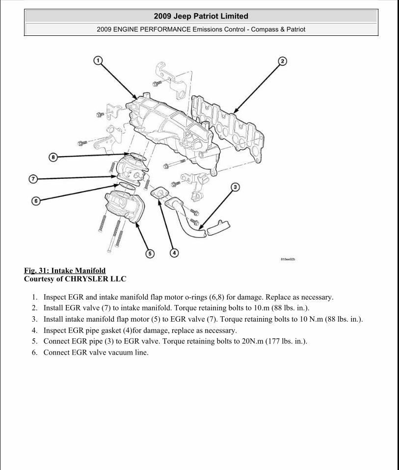
Fig. 31: Intake ManifoldCourtesy of CHRYSLER LLC
1. Inspect EGR and intake manifold flap motor o-rings (6,8) for damage. Replace as necessary. 2. Install EGR valve (7) to intake manifold. Torque retaining bolts to 10.m (88 lbs. in.). 3. Install intake manifold flap motor (5) to EGR valve (7). Torque retaining bolts to 10 N.m (88 lbs. in.). 4. Inspect EGR pipe gasket (4)for damage, replace as necessary. 5. Connect EGR pipe (3) to EGR valve. Torque retaining bolts to 20N.m (177 lbs. in.). 6. Connect EGR valve vacuum line.
2009 Jeep Patriot Limited2009 ENGINE PERFORMANCE Emissions Control - Compass & Patriot
a
Saturday, September 08, 2012 1:31:40 PM Page 37 © 2006 Mitchell Repair Information Company, LLC.

Fig. 32: Engine CoverCourtesy of CHRYSLER LLC
7. Install engine cover. Refer to Engine - Installation .
Fig. 33: Air Inlet DuctCourtesy of CHRYSLER LLC
8. Connect negative battery cable. 9. Install air inlet duct (3).
ON-BOARD DIAGNOSTICS
TASK MANAGER
2009 Jeep Patriot Limited2009 ENGINE PERFORMANCE Emissions Control - Compass & Patriot
a
Saturday, September 08, 2012 1:31:40 PM Page 38 © 2006 Mitchell Repair Information Company, LLC.

Description
DESCRIPTION
The PCM is responsible for efficiently coordinating the operation of all the emissions-related components. The PCM is also responsible for determining if the diagnostic systems are operating properly. The software designed to carry out these responsibilities is call the "Task Manager".
GLOSSARY OF TERMS
APPS Accelerator Pedal Position SensorAAT Ambient Air TemperatureABS Anti-Lock Brake SystemASD Auto Shut DownBARO BarometricCGW Central GatewayCKP Crankshaft Position SensorCMP Camshaft Position SensorCMTC Compass/Mini-Trip ComputerDCHA Diesel Cabin Heater AssistDLC Data Link ConnectorDTC Diagnostic Trouble CodeEATX Electronic Automatic TransaxleECT Engine Coolant TemperatureECM Engine Control ModuleEGR Exhaust Gas RecirculationETC Electronic Throttle ControlGEN GeneratorGPEC Global Powertrain Engine ControllerFCM Front Control ModuleFDCM Final Drive Control ModuleIAT Intake/Inlet Air TemperatureIAC Idle Air ControlIOD Ignition Off-DrawIPM Integrated Power ModuleJTEC Jeep Truck Engine ControllerKS Knock SensorLDP Leak Detection PumpMAP Manifold Air PressureMDS Multi Displacement SystemMIC Mechanical Instrument ClusterMIL Malfunction Indicator Lamp
2009 Jeep Patriot Limited2009 ENGINE PERFORMANCE Emissions Control - Compass & Patriot
a
Saturday, September 08, 2012 1:31:40 PM Page 39 © 2006 Mitchell Repair Information Company, LLC.

Operation
OPERATION
The Task Manager determines when tests happen and when functions occur. Many of the diagnostic steps required by OBD II must be performed under specific operating conditions. The Task Manager software organizes and prioritizes the diagnostic procedures. The job of the Task Manager is to determine if conditions are appropriate for tests to be run, monitor the parameters for a trip for each test, and record the results of the test. Following are the responsibilities of the Task Manager software:
Test Sequence MIL Illumination Diagnostic Trouble Codes (DTCs)
MTV Manifold Tuning ValveNGC Next Generation ControllerNVLD Natural Vacuum Leak DetectionO2S Oxygen SensorOBD On Board DiagnosticPDC Power Distribution CenterPCI Programmable Communication InterfacePCM Powertrain Control ModulePCV Positive Crankcase VentilationPEP Peripheral Expansion PortSBEC Single Board Engine ControllerSCM Steering Control ModuleS/C Speed ControlSKIM Sentry Key Immobilizer ModuleSKIS Sentry Key Immobilizer SystemSKREEM Sentry Key Remote Entry ModuleSKREES Sentry Key Remote Entry SystemSOL SolenoidSRV Short Runner ValveTCM Transmission Control ModuleTCC Torque Converter ClutchTIP Throttle Inlet PressureTIPM Totally Integrated Power ModuleTP Throttle PositionTPMS Tire Pressure Monitor SystemTRS Transmission Range SensorVSS Vehicle Speed Sensor/SignalWCM Wireless Control Module
2009 Jeep Patriot Limited2009 ENGINE PERFORMANCE Emissions Control - Compass & Patriot
a
Saturday, September 08, 2012 1:31:40 PM Page 40 © 2006 Mitchell Repair Information Company, LLC.

Trip Indicator Freeze Frame Data Storage Similar Conditions Window
Test Sequence
In many instances, emissions systems must fail diagnostic tests more than once before the PCM illuminates the MIL. These tests are known as 'two trip monitors.' Other tests that turn the MIL lamp on after a single failure are known as 'one trip monitors.' A trip is defined as 'start the vehicle and operate it to meet the criteria necessary to run the given monitor.'
Many of the diagnostic tests must be performed under certain operating conditions. However, there are times when tests cannot be run because another test is in progress (conflict), another test has failed (pending) or the Task Manager has set a fault that may cause a failure of the test (suspend).
Pending
Under some situations the Task Manager will not run a monitor if the MIL is illuminated and a fault is stored from another monitor. In these situations, the Task Manager postpones monitors pendingresolution of the original fault. The Task Manager does not run the test until the problem is remedied.
For example, when the MIL is illuminated for an Oxygen Sensor fault, the Task Manager does not run the Catalyst Monitor until the Oxygen Sensor fault is remedied. Since the Catalyst Monitor is based on signals from the Oxygen Sensor, running the test would produce inaccurate results.
Conflict
There are situations when the Task Manager does not run a test if another monitor is in progress. In these situations, the effects of another monitor running could result in an erroneous failure. If this conflict is present, the monitor is not run until the conflicting condition passes. Most likely the monitor will run later after the conflicting monitor has passed.
For example, if the Fuel System Monitor is in progress, the Task Manager does not run the catalyst Monitor. Since both tests monitor changes in air/fuel ratio and adaptive fuel compensation, the monitors will conflict with each other.
Suspend
Occasionally the Task Manager may not allow a two trip fault to mature. The Task Manager will suspendthe maturing of a fault if a condition exists that may induce an erroneous failure. This prevents illuminating the MIL for the wrong fault and allows more precise diagnosis.
For example, if the PCM is storing a one trip fault for the Oxygen Sensor and the catalyst monitor, the Task Manager may still run the catalyst Monitor but will suspend the results until the Oxygen Sensor Monitor either passes or fails. At that point the Task Manager can determine if the catalyst system is actually failing or if an Oxygen Sensor is failing.
2009 Jeep Patriot Limited2009 ENGINE PERFORMANCE Emissions Control - Compass & Patriot
a
Saturday, September 08, 2012 1:31:40 PM Page 41 © 2006 Mitchell Repair Information Company, LLC.

MIL Illumination
The PCM Task Manager carries out the illumination of the MIL. The Task Manager triggers MIL illumination upon test failure, depending on monitor failure criteria.
The Task Manager Screen shows both a Requested MIL state and an Actual MIL state. When the MIL is illuminated upon completion of a test for a good trip, the Requested MIL state changes to OFF. However, the MIL remains illuminated until the next key cycle. (On some vehicles, the MIL will actually turn OFF during the third good trip) During the key cycle for the third good trip, the Requested MIL state is OFF, while the Actual MIL state is ON. After the next key cycle, the MIL is not illuminated and both MIL states read OFF.
Diagnostic Trouble Codes (DTCs)
With OBD II, different DTC faults have different priorities according to regulations. As a result, the priorities determine MIL illumination and DTC erasure. DTCs are entered according to individual priority. DTCs with a higher priority overwrite lower priority DTCs.
Priorities
Priority 0 -Non-emissions related trouble codes. Priority 1 - One trip failure of a two trip fault for non-fuel system and non-misfire. (MIL Off) Priority 2 - One trip failure of a two trip fault for fuel system (rich/lean) or misfire. (MIL Off) Priority 3 - Two trip failure for a non-fuel system and non-misfire or matured one trip comprehensive component fault. (MIL On) Priority 4 - Two trip failure or matured fault for fuel system (rich/lean) and misfire or one trip catalyst damaging misfire. Catalyst damage misfire is a 2 trip MIL. The MIL flashes on the first trip when catalyst damage misfire levels are present. (MIL On)
Non-emissions related failures have no priority. One trip failures of two trip faults have low priority. Two trip failures or matured faults have higher priority. One and two trip failures of fuel system and misfire monitor take precedence over non-fuel system and non-misfire failures.
DTC Self Erasure
With one trip components or systems, the MIL is illuminated upon test failure and DTCs are stored.
Two trip monitors are components requiring failure in two consecutive trips for MIL illumination. Upon failure of the first test, the Task Manager enters a maturing code. If the component fails the test for a second time the code matures and a DTC is set.
After three good trips the MIL is extinguished and the Task Manager automatically switches the trip counter to a warm-up cycle counter. DTCs are automatically erased following 40 warm-up cycles if the component does not fail again.
For misfire and fuel system monitors, the component must pass the test under a Similar Conditions Window in order to record a good trip. A Similar Conditions Window is when engine RPM is within ±375 RPM and load is within ±20% of when the fault occurred.
2009 Jeep Patriot Limited2009 ENGINE PERFORMANCE Emissions Control - Compass & Patriot
a
Saturday, September 08, 2012 1:31:40 PM Page 42 © 2006 Mitchell Repair Information Company, LLC.

DTCs can be erased anytime with a scan tool. Erasing the DTC with the scan tool erases all OBD II information. The scan tool automatically displays a warning that erasing the DTC will also erase all OBD II monitor data. This includes all counter information for warm-up cycles, trips and Freeze Frame.
Trip Indicator
The Trip is essential for running monitors and extinguishing the MIL. In OBD II terms, a trip is a set of vehicle operating conditions that must be met for a specific monitor to run. All trips begin with a key cycle.
Good Trip
The Good Trip counters are as follows:
Global Good Trip Fuel System Good Trip Misfire Good Trip Alternate Good Trip (appears as a Global Good Trip on scan tool)
a. Comprehensive Components b. Major Monitor
Warm-Up Cycles
Global Good Trip
To increment a Global Good Trip, the Oxygen sensor and Catalyst efficiency monitors must have run and passed, and 2 minutes of engine run time.
Fuel System Good Trip
To count a good trip (three required) and turn off the MIL, the following conditions must occur:
Engine in closed loop Operating in Similar Conditions Window Short Term multiplied by Long Term less than threshold Less than threshold for a predetermined time
If all of the previous criteria are met, the PCM will count a good trip (three required) and turn off the MIL.
Misfire Good Trip
NOTE: It is important to understand that a component does not have to fail under a similar window of operation to mature. It must pass the test under a Similar Conditions Window when it failed to record a Good Trip for DTC erasure for misfire and fuel system monitors.
2009 Jeep Patriot Limited2009 ENGINE PERFORMANCE Emissions Control - Compass & Patriot
a
Saturday, September 08, 2012 1:31:40 PM Page 43 © 2006 Mitchell Repair Information Company, LLC.

If the following conditions are met the PCM will count one good trip (three required) in order to turn off the MIL:
Operating in Similar Condition Window 1000 engine revolutions with no misfire
Alternate Good Trip
Alternate Good Trips are used in place of Global Good Trips for Comprehensive Components and Major Monitors. If the Task Manager cannot run a Global Good Trip because a component fault is stopping the monitor from running, it will attempt to count an Alternate Good Trip.
The Task Manager counts an Alternate Good Trip for Comprehensive components when the following conditions are met:
Two minutes of engine run time, idle or driving No other faults occur
The Task Manager counts an Alternate Good Trip for a Major Monitor when the monitor runs and passes. Only the Major Monitor that failed needs to pass to count an Alternate Good Trip.
Warm-Up Cycles
Once the MIL has been extinguished by the Good Trip Counter, the PCM automatically switches to a Warm-Up Cycle Counter that can be viewed on the scan tool. Warm-Up Cycles are used to erase DTCs and Freeze Frames. Forty Warm-Up cycles must occur in order for the PCM to self-erase a DTC and Freeze Frame. A Warm-Up Cycle is defined as follows:
Engine coolant temperature must start below and rise above 71° C (160° F) Engine coolant temperature must rise by 4.5° C (40° F) No further faults occur
Freeze Frame Data Storage
Once a failure occurs, the Task Manager records several engine operating conditions and stores it in a Freeze Frame. The Freeze Frame is considered one frame of information taken by an on-board data recorder. When a fault occurs, the PCM stores the input data from various sensors so that technicians can determine under what vehicle operating conditions the failure occurred.
The data stored in Freeze Frame is usually recorded when a system fails the first time for two trip faults. Freeze Frame data will only be overwritten by a different fault with a higher priority.
CAUTION: Erasing DTCs, either with the scan tool; or by disconnecting the battery, also clears all Freeze Frame data.
2009 Jeep Patriot Limited2009 ENGINE PERFORMANCE Emissions Control - Compass & Patriot
a
Saturday, September 08, 2012 1:31:40 PM Page 44 © 2006 Mitchell Repair Information Company, LLC.

Similar Conditions Window
The Similar Conditions Window displays information about engine operation during a monitor. Absolute MAP (engine load) and Engine RPM are stored in this window when a failure occurs. There are two different Similar conditions Windows: Fuel System and Misfire.
FUEL SYSTEM
Fuel System Similar Conditions Window - An indicator that 'Absolute MAP When Fuel Sys Fail' and 'RPM When Fuel Sys Failed' are all in the same range when the failure occurred. Indicated by switching from 'NO' to 'YES'. Absolute MAP When Fuel Sys Fail - The stored MAP reading at the time of failure. Informs the user at what engine load the failure occurred. Absolute MAP - A live reading of engine load to aid the user in accessing the Similar Conditions Window. RPM When Fuel Sys Fail - The stored RPM reading at the time of failure. Informs the user at what engine RPM the failure occurred. Engine RPM - A live reading of engine RPM to aid the user in accessing the Similar Conditions Window. Adaptive Memory Factor - The PCM utilizes both Short Term Compensation and Long Term Adaptive to calculate the Adaptive Memory Factor for total fuel correction. Upstream O2S Volts - A live reading of the Oxygen Sensor to indicate its performance. For example, stuck lean, stuck rich, etc. SCW Time in Window (Similar Conditions Window Time in Window) - A timer used by the PCM that indicates that, after all Similar Conditions have been met, if there has been enough good engine running time in the SCW without failure detected. This timer is used to increment a Good Trip. Fuel System Good Trip Counter - A Trip Counter used to turn OFF the MIL for Fuel System DTCs. To increment a Fuel System Good Trip, the engine must be in the Similar Conditions Window, Adaptive Memory Factor must be less than calibrated threshold and the Adaptive Memory Factor must stay below that threshold for a calibrated amount of time. Test Done This Trip - Indicates that the monitor has already been run and completed during the current trip.
MISFIRE
Same Misfire Warm-Up State - Indicates if the misfire occurred when the engine was warmed up (above 71°C [160°F]). In Similar Misfire Window - An indicator that 'Absolute MAP When Misfire Occurred' and 'RPM When Misfire Occurred' are all in the same range when the failure occurred. Indicated by switching from 'NO' to 'YES'. Absolute MAP When Misfire Occurred - The stored MAP reading at the time of failure. Informs the user at what engine load the failure occurred. Absolute MAP - A live reading of engine load to aid the user in accessing the Similar Conditions Window.
2009 Jeep Patriot Limited2009 ENGINE PERFORMANCE Emissions Control - Compass & Patriot
a
Saturday, September 08, 2012 1:31:40 PM Page 45 © 2006 Mitchell Repair Information Company, LLC.

RPM When Misfire Occurred - The stored RPM reading at the time of failure. Informs the user at what engine RPM the failure occurred. Engine RPM - A live reading of engine RPM to aid the user in accessing the Similar Conditions Window. Adaptive Memory Factor - The PCM utilizes both Short Term Compensation and Long Term Adaptive to calculate the Adaptive Memory Factor for total fuel correction. 200 Rev Counter - Counts 0-100 720 degree cycles. SCW Cat 200 Rev Counter - Counts when in similar conditions. SCW FTP 1000 Rev Counter - Counts 0-4 when in similar conditions. Misfire Good Trip Counter - Counts up to three to turn OFF the MIL.
OBD II MONITOR RUN PROCESS
The following procedure has been established to assist technicians in the field with enabling and running OBD II Monitors. The order listed in the following procedure is intended to allow the technician to effectively complete each monitor and to set the CARB Readiness Status in the least time possible.
Monitor Preliminary Checks:
1. Plug a scan tool into the vehicle's Data Link Connector (DLC). 2. Turn the ignition, KEY ON - ENGINE OFF. Watch for MIL lamp illumination during the bulb check.
MIL lamp must have illuminated, if not, repair MIL lamp. 3. Using a scan tool check for Powertrain related DTCs.
Verify that No Emissions Related DTCs are Present. If an Emissions DTC is Present, the OBD II Monitors may not run and the CARB Readiness will not update. The Emissions related DTC, will need to be repaired, then cleared. By clearing DTCs, the OBD Monitors will need to be run and completed to set the CARB Readiness Status.
Using the scan tool check the CARB Readiness Status.
Do all the CARB Readiness Status Locations read YES?
NOTE: Once the monitor run process has begun, do not turn off the ignition. By turning the ignition key off, monitor enabling conditions will be lost. EVAP Monitor runs after key off. By performing a Battery Disconnect, or Selecting Erase DTCs, the CARB Readiness and all additional OBD II information will be cleared.
NOTE: Only the monitors, which are not YES in the CARB Readiness Status, need to be completed. Specific criteria need to be met for each monitor. The most efficient order to run the monitors has been outlined below, including suggestions to aid the process.
2009 Jeep Patriot Limited2009 ENGINE PERFORMANCE Emissions Control - Compass & Patriot
a
Saturday, September 08, 2012 1:31:40 PM Page 46 © 2006 Mitchell Repair Information Company, LLC.

YES - all monitors have been completed and this vehicle is ready to be I/M or Emission Tested. NO - then the following procedure needs to be followed to run/complete all available monitors.
Evaporative Emission System Leak Detection with Purge Monitor
This monitor requires a cool down cycle, usually an overnight soak for at least 8 hours without the engine running. The ambient temperature must decrease overnight - parking the vehicle outside is advised. To run this test the fuel level must be between 15-85% full. Criteria for EVAP monitor:
Engine off time greater than one hour. Fuel Level between 15% and 85%. Start Up ECT and IAT within 10°C (18°F). Vehicle started and run until Purge Monitor reports a result.
Catalyst / O2 Monitor
The Catalyst and O2 Monitor information are acquired and processed at the same time. Most vehicles will need to be driven at highway speed (less than 50 mph) (73km/h) for a few minutes. Some vehicles run the monitor at idle in drive. If the vehicle is equipped with a manual transmission, using 4th gear may assist in meeting the monitor running criteria.
Engine RPM between 1200 to 3000. Engine temperature greater than 70°C (158°F) Engine run time greater than 92 seconds MAP between 10 - 20 kPa (7.5 - 15 Hg) Vehicle speed between 20 - 70 mph (29-103 km/h)
EGR Monitor
After the vehicle has reached the below conditions and during a throttle decel the EGR monitor will run.
Engine RPM between 1375 - 2500 Engine temperature greater than 70°C (158°F) Engine run time greater than 125 seconds Vehicle speed between 25 - 70 mph (37-103 km/h)
NOTE: If the vehicle does not report a result and the conditions where correct. It may take up to two weeks to fail the small leak monitor. DO NOT use this test to attempt to determine a fault. Use the appropriate service information procedure for finding a small leak. If there are no faults and the conditions are correct this test will run and report a pass. Note the Small leak test can find leaks less than 10 thousands of an inch. If a small leak is present it takes approximately one week of normal driving to report a failure.
2009 Jeep Patriot Limited2009 ENGINE PERFORMANCE Emissions Control - Compass & Patriot
a
Saturday, September 08, 2012 1:31:40 PM Page 47 © 2006 Mitchell Repair Information Company, LLC.

O2 Sensor Heater Monitor
This monitor is now continuously running once the heaters are energized. Pass information will be processed at power down.
Misfire Monitor
The Misfire Monitor is a continuous two-trip monitor. The monitor uses two different tests/counters:
200 Revolution Counter - Looks for misfire that can cause immediate catalyst damage. 1000 Revolution Counter - Looks for misfire that can cause emissions to increase 1.5 times the Federal Test Procedure (FTP) standards. This test must also identify misfire percentages that might cause a "durability demonstration vehicle" to fail an Inspection and Maintenance Program tailpipe emissions test.
NOTE: The Adaptive Numerator must be learned before the PCM will run the Misfire Monitor. The PCM updates the Adaptive Numerator at every key-ON, and is relearned after battery disconnect. The Misfire Monitor will not run until the Adaptive Numerator has updated since the last battery disconnect. If the Adaptive Numerator is equal to the default value then the PCM knows that the Adaptive Numerator has not been learned and does not permit the Misfire Monitor to run. If the Adaptive Numerator exceeds a calibrated percentage, the PCM sets a DTC for CKP NOT LEARNED and illuminates the MIL.
2009 Jeep Patriot Limited2009 ENGINE PERFORMANCE Emissions Control - Compass & Patriot
a
Saturday, September 08, 2012 1:31:40 PM Page 48 © 2006 Mitchell Repair Information Company, LLC.