Manual PX 25-4 - Dutch Blower Luchtbehandelingskasten · The PX 25/4 pressure sensor measures a...
8
Description: PX 25/4 Type1 (0-0.5...0-2.0"WC) and Type2 (0-5...0-30"WC) Doc.nr.: 111034 Type: MANUAL Number of pages: 8 Version: V1.1 File: Do111043 PX25-4 v11 EN.wpd Software: 110770 PX25_4 By: RK Date: 14-12-2011 VDH Products BV - Roden - Holland Signed: File: Doc-11 Manual PX 25-4 differential pressure gauge
Transcript of Manual PX 25-4 - Dutch Blower Luchtbehandelingskasten · The PX 25/4 pressure sensor measures a...

Description: PX 25/4 Type1 (0-0.5...0-2.0"WC) and Type2 (0-5...0-30"WC)
Doc.nr.: 111034
Type: MANUAL Number of pages: 8 Version: V1.1
File: Do111043 PX25-4 v11 EN.wpdSoftware: 110770 PX25_4
By: RK Date: 14-12-2011
VDH Products BV - Roden - Holland Signed: File: Doc-11
Manual PX 25-4differential pressure gauge

Operation manual Document nr. : 111034 Version : V1.1
PX 25/4 Client: General Page : 2 van 8
The information contained in this document is assumed to be accurate. However VDH Products BVaccepts no liability for eventual mistakes or errors and has the right to change this document withoutnotice.
Content
1. Technical specifications. . . . . . . . . . . . . . . . . . . . . . . . . . . . . . . . . . . . . . . . . . . . . . . . . . . . . . . . . . . 3
2. Functional specifications. . . . . . . . . . . . . . . . . . . . . . . . . . . . . . . . . . . . . . . . . . . . . . . . . . . . . . . . . . . 4
3. Configuration. . . . . . . . . . . . . . . . . . . . . . . . . . . . . . . . . . . . . . . . . . . . . . . . . . . . . . . . . . . . . . . . . . . . 5
5. Dimensions. . . . . . . . . . . . . . . . . . . . . . . . . . . . . . . . . . . . . . . . . . . . . . . . . . . . . . . . . . . . . . . . . . . . . 7
6. Connection diagrams. . . . . . . . . . . . . . . . . . . . . . . . . . . . . . . . . . . . . . . . . . . . . . . . . . . . . . . . . . . . . 8
7. Address. . . . . . . . . . . . . . . . . . . . . . . . . . . . . . . . . . . . . . . . . . . . . . . . . . . . . . . . . . . . . . . . . . . . . . . . 8

Operation manual Document nr. : 111034 Version : V1.1
PX 25/4 Client: General Page : 3 van 8
1. Technical specifications.
Type PX 25-4 Type 1 0..0,5"WC .... 0-2"WC(0..500Pa max.)
PX 25-4 Type 20..5"WC .... 0-30"WC(0..7500Pa max.)
Type number 910.080165 910.080166
Voltage 12 - 30Vdc
Current consumption max 100 mA
Control dipswitches (S1..4) and potentiometer (P1) on circuit board
Readout None
Network connection None
Dimensions housing 138 x 33 x 62 mm (whd)
Operating temperature 0/+60OC
Storage temperature 0/+60OC
Measuring range depending on settings (dipswitches)
Range-1 = S1 off, S2 off 0 - ½ “ WCD ( 0 - 125 Pa) 0 - 5 “ WCD ( 0 - 1250 Pa)
Range-2 = S1 on, S2 off 0 - 1 “ WCD ( 0 - 250 Pa) 0 - 10 “ WCD ( 0 - 2500 Pa)
Range-3 = S1 off, S2 on 0 - 2 " WCD ( 0 - 500 Pa) 0 - 20 " WCD ( 0 - 5000 Pa)
Range-4 = S1 on, S2 on Undefined 0 - 30 " WCD ( 0 - 7500 Pa)
Maximum pressure 1 bar (400 “ WCD, 100 kPa)
Accuracy * 3% of measurement +/- 0,5%F.S.O.
< 1,5% F.S.O.
Offset shift due to temperature variation
None (less than resolution) < 8 Pa
Offset stability < 0.1 Pa/year < 8 Pa/year
Output signal 4 - 20 mA
Output load 50 - 350 Ohm
Electrical connections Plugable connector with screw terminals (wiring: 0,2..2,5mm2)
Pressure High and Lowconnections
2 barbed fittings for use with 1/8" (ø4mm) ID vinyl or rubbertubing
*) Accuracies are valid at 25 C and 1013 mBar.

Operation manual Document nr. : 111034 Version : V1.1
PX 25/4 Client: General Page : 4 van 8
2. Functional specifications.
2.1 Installation.Location
The PX 25/4 pressure sensor should be placed in a as clean, dry and vibration freelocation.
Pressure Connections The PX 25/4 pressure sensor uses 2 barbed fittings for use with 1/8” ID vinyl or rubber tubing(ø4mm). Attach tubing from positive pressure or higher pressure source to port marked ‘High’and lower or negative pressure to port marked ‘Low’. Arrange tubing to minimize stress onconnections. If possible, mount with ports facing down to aid in moisture drainage.Note: When removing tubing care should be used to avoid breaking the ports. In some casesthe tubing should be cut off, rather than pulled off, especially if stiff tubing is being used.
MountingAttach the PX 25/4 sensor to the mounting surface using 4 fasteners inserted through the fourmounting holes located on the top and bottom side of the case. Do not over tighten.
2.2 Operation.The PX 25/4 pressure sensor measures a differential pressure and outputs a 4/20mA currentsignal which corresponds to the measured differential pressure. The sensor can be configured to output its maximum current (20 mA) at different maximumpressures. For Type 1 the maximum pressures can be;
½“ WCD (125 Pa), 1" WCD ( 250 Pa) or 2" WCD ( 500 Pa)And for Type 2 the maximum can be;
5“ WCD ( 1250 Pa), 10" WCD ( 2500 Pa), 20" WCD ( 5000 Pa) or 30“ WCD ( 7500 Pa).The output varies from 4 mA (at no differential pressure) to 20 mA (at the maximum pressure)depending on settings.Using the offset potentiometer P1 (with S4=on), a offset value can be set which is added to theoutput.

Operation manual Document nr. : 111034 Version : V1.1
PX 25/4 Client: General Page : 5 van 8
3. Configuration.Using the dipswitches on the circuit board, the sensor can be adjusted in measurement and offsetrange. The offset can be set using the potentiometer which is located besides the dipswitches.
The circuit board contains 4 dipswitches (S1..4), number 1 and 2 are used to select themeasurement range, number 3 is used to adjust the measurement speed and number 4 is used toselect whether the offset set by the potentiometer should be used or not.
In the image shown, the dipswitches are switched off, by sliding them to the top they are switchedon. The function of the different switches are described below.
To adjust the measurement range, dipswitch 1 and 2 can be used. The table below shows thedipswitch settings and the corresponding measurement and offset range for both type 1 and type 2sensors.
PX 25-4 Type 1 Type 2
Dip-switch 1 and 2
Measurementrange
Offset range (P1) Measurementrange
Offset range (P1)
S1 offS2 off
0 - ½“ WCD( 0 - 125 Pa)
-0.2 to +0.2 “WCD(-50 Pa to +50 Pa)
0 - 5" WCD ( 0 - 1250 Pa)
-2 to +2 “WCD(-500 Pa to +500 Pa)
S1 onS2 off
0 - 1“ WCD( 0 - 250 Pa)
-0.4 to +0.4 “WCD(-100 Pa to +100 Pa)
0 - 10" WCD ( 0 - 2500 Pa)
-4 to +4 “WCD(-1000 Pa to +1000 Pa)
S1 offS2 on
0 - 2“ WCD( 0 - 500 Pa)
-0.4 to +0.4 “WCD(-100 Pa to +100 Pa)
0 - 20" WCD ( 0 - 5000 Pa)
-4 to +4 “WCD(-1000 Pa to +1000 Pa)
S1 onS2 on
Undefined Undefined 0 - 30" WCD ( 0 - 7500 Pa)
-4 to +4 “WCD(-1000 Pa to +1000 Pa)
Independent from the selected range, the output will be 4 mA when the pressure is 0 Pa. However, the output will be 20 mA at the maximum value of the selected range.

Operation manual Document nr. : 111034 Version : V1.1
PX 25/4 Client: General Page : 6 van 8
Using dipswitch number 3, the sensors speed of response can be adjusted. A quick response willhave the effect that the output will be responding sooner on a changed pressure value, but thesignal will also fluctuate more. An easier response will respond slower on a changed pressurevalue, but will result in a more constant output signal.
Dipswitch 3 meaning
S3 off Quick response.
S3 on Easy response.
The amount of offset that will be added to the output signal can be changed using thepotentiometer P1. Dipswitch number 4 determines if the chosen offset should be used or not.
Dipswitch 4 meaning
S4 off The offset will not be used.
S4 on The offset will be used.
The offsetvalue set using the potentiometer indicates at what pressure value the sensor shouldoutput at signal of 4 mA. By setting the offset to a value of -10 Pa, a measured pressure value of 0Pa will not result in an output of 4 mA, but as soon as the pressure value has reached 10 Pa, theoutputsignal will be 4 mA.
Operation manual Document nr. : 111034 Version : V1.1
PX 25/4 Client: General Page : 7 van 8
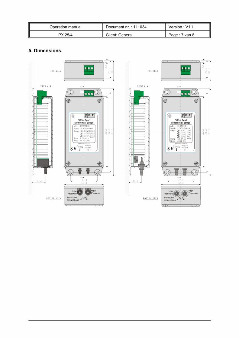
5. Dimensions.

Operation manual Document nr. : 111034 Version : V1.1
PX 25/4 Client: General Page : 8 van 8
6. Connection diagrams.
7. Address.VDH Products BV Telefoon +31 (0)50 - 30 28 900Produktieweg 1 Fax +31 (0)50 - 30 28 9809301 ZS Roden Email: [email protected] Internet: www.vdhproducts.nl