![7570 Alarms Dictionary 3bl77057acbarkzza 04 en[1]](https://static.fdocuments.us/doc/165x107/5439b35aafaf9fb92e8b54a1/7570-alarms-dictionary-3bl77057acbarkzza-04-en1.jpg)
Manual-PR90-EN-2docs.encoderhohner.com/SERIE-PR90/Manual-PR90-EN-2.0web.pdfAutomatic overload...
24
v2.0
Transcript of Manual-PR90-EN-2docs.encoderhohner.com/SERIE-PR90/Manual-PR90-EN-2.0web.pdfAutomatic overload...

v2.0

PR90 / PR90H
FeaturesAuto sensig features Working marginsProtection
p. 5
p. 6
p. 6
p. 7
CONNECT
RequirementsConnection StepsConnect to PCInstall softwareRun the program
p. 9
p. 10
p. 10
p. 10
p. 13
PROGRAM
OverviewProgramming screenProgramming stepsMonitoring screenTroubleshootingConsiderations
p. 15
p. 16
p. 17
p. 19
p. 21
p. 22
Contents 3
USER MANUAL PR90 / PR90H

PR90 / PR90H
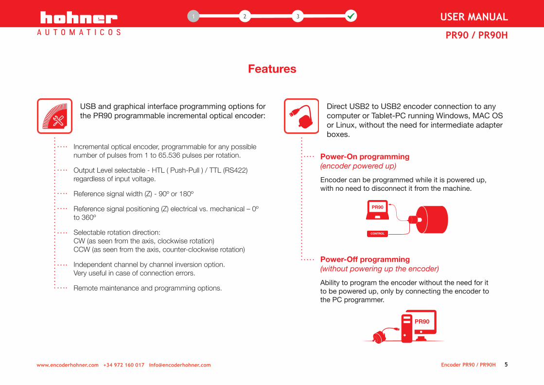
USB and graphical interface programming options for the PR90 programmable incremental optical encoder:
Incremental optical encoder, programmable for any possible number of pulses from 1 to 65.536 pulses per rotation.
Output Level selectable - HTL ( Push-Pull ) / TTL (RS422) regardless of input voltage.
Reference signal width (Z) - 90º or 180º
Reference signal positioning (Z) electrical vs. mechanical – 0º to 360º
Selectable rotation direction:CW (as seen from the axis, clockwise rotation) CCW (as seen from the axis, counter-clockwise rotation)
Independent channel by channel inversion option. Very useful in case of connection errors.
Remote maintenance and programming options.
Features
Direct USB2 to USB2 encoder connection to any computer or Tablet-PC running Windows, MAC OS or Linux, without the need for intermediate adapter boxes.
Power-On programming (encoder powered up)
Encoder can be programmed while it is powered up, with no need to disconnect it from the machine.
Power-Off programming (without powering up the encoder)
Ability to program the encoder without the need for it to be powered up, only by connecting the encoder to the PC programmer.
Encoder PR90 / PR90H 5
PR90
PR90
CONTROL
www.encoderhohner.com +34 972 160 017 [email protected]
1 1 32 USER MANUAL
PR90 / PR90H
Auto sensing features
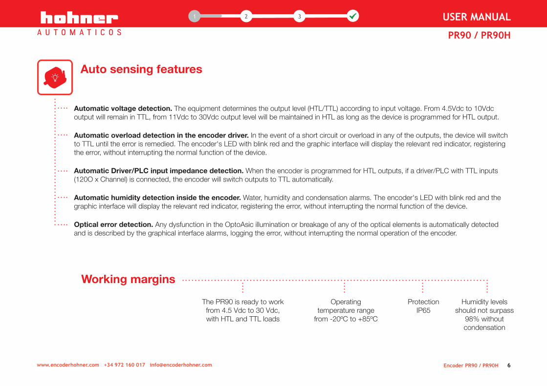
Automatic voltage detection. The equipment determines the output level (HTL/TTL) according to input voltage. From 4.5Vdc to 10Vdc output will remain in TTL, from 11Vdc to 30Vdc output level will be maintained in HTL as long as the device is programmed for HTL output.
Automatic overload detection in the encoder driver. In the event of a short circuit or overload in any of the outputs, the device will switch to TTL until the error is remedied. The encoder's LED with blink red and the graphic interface will display the relevant red indicator, registering the error, without interrupting the normal function of the device.
Automatic Driver/PLC input impedance detection. When the encoder is programmed for HTL outputs, if a driver/PLC with TTL inputs (120O x Channel) is connected, the encoder will switch outputs to TTL automatically.
Automatic humidity detection inside the encoder. Water, humidity and condensation alarms. The encoder's LED with blink red and the graphic interface will display the relevant red indicator, registering the error, without interrupting the normal function of the device.
Optical error detection. Any dysfunction in the OptoAsic illumination or breakage of any of the optical elements is automatically detected and is described by the graphical interface alarms, logging the error, without interrupting the normal operation of the encoder.
Working margins
The PR90 is ready to work from 4.5 Vdc to 30 Vdc, with HTL and TTL loads
Operating temperature range
from -20ºC to +85ºC
Humidity levels should not surpass
98% without condensation
ProtectionIP65
Encoder PR90 / PR90H 6www.encoderhohner.com +34 972 160 017 [email protected]
1 1 32 USER MANUAL
PR90 / PR90H

Protection
Over voltage and power supply inversion protection. The encoder is protected to prevent its destruction in case of reverse polarity of power and/or spikes exceeding 35Vdc.
Voltage drops. The device stops working below 3.9 Vdc. Up to this point the PR90 maintains the outputs at standard TTL levels, and if the voltage drop has been excessively slow the encoder goes into protection mode; to reset the rated voltage to recover its normal operation you must just turn it off and on again.
Electrostatic and/or electromagnetic discharges. Complies with the EMC directive (UNE-EN 61000-6-2:2006 + ERR:2009 and UNE-EN 61000-6-3:2007 + A1:2012). Although the equipment is protected to withstand electrostatic discharge above ± 15KVolt., occasionally the signal may lose a certain number of pulses during the discharge, at this point the equipment will reset the signal in under 100msec, the standard delay for a Watch-Dog circuit.
Active reset of the high-efficiency uController. This circuit resets uController operation in extreme cases of malfunction. For example, this situation can occur in unstable or high-noise power connections.
False power connections. The encoder is protected to withstand being switched on and off repeatedly within the margins of usual operation, without the equipment being harmed.
The electronic circuit has ultra-fast electronic fuses; in the event of a fault or failure, these fuses avoid greater damage and more expensive repairs.
Electronics designed under the BSI security regulations, so as to avoid smoke and fire.
4-layer printed circuit designed under MIL standards, to offer greater mechanical robustness in order to avoid external radio-magnetic influences.
Encoder PR90 / PR90H 7
It is not recommendable, like with any other electrical device, to turn the equipment on and off repeatedly in rapid succession while connected to mains power.
www.encoderhohner.com +34 972 160 017 [email protected]
1 1 32 USER MANUAL
PR90 / PR90H

connect
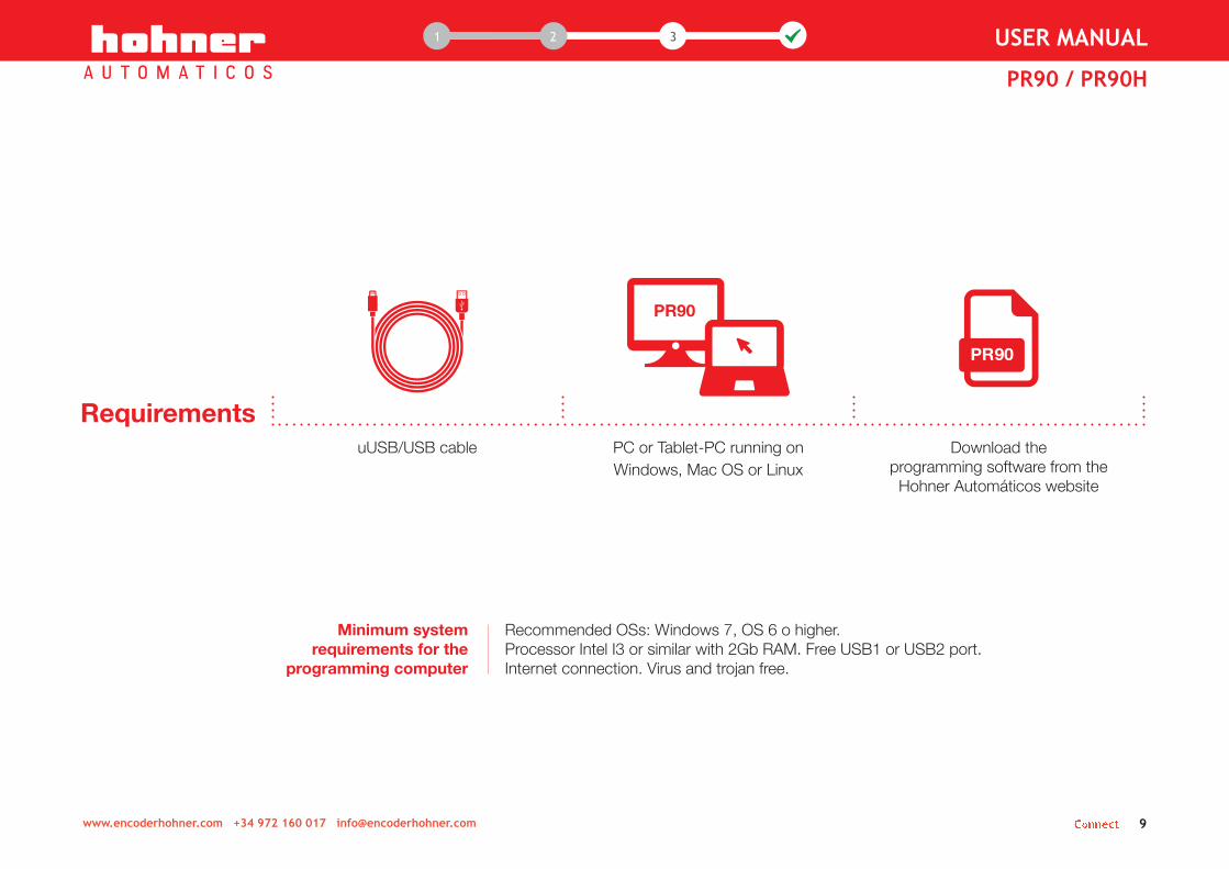
Requirements uUSB/USB cable PC or Tablet-PC running on
Windows, Mac OS or Linux Download the
programming software from the Hohner Automáticos website
Connect 9www.encoderhohner.com +34 972 160 017 [email protected]
1 1 32 USER MANUAL
PR90 / PR90H
Recommended OSs: Windows 7, OS 6 o higher.Processor Intel I3 or similar with 2Gb RAM. Free USB1 or USB2 port. Internet connection. Virus and trojan free.
Minimum system requirements for the
programming computer
www.encoderhohner.com +34 972 160 017 [email protected] Connect 10
1 1 32 USER MANUAL
PR90 / PR90H
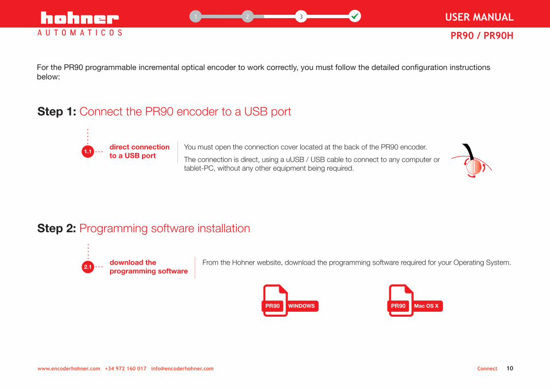
From the Hohner website, download the programming software required for your Operating System.2.1
download the programming software
Step 2: Programming software installation
Mac OS XWINDOWS
For the PR90 programmable incremental optical encoder to work correctly, you must follow the detailed configuration instructions below:
Step 1: Connect the PR90 encoder to a USB port
You must open the connection cover located at the back of the PR90 encoder.
The connection is direct, using a uUSB / USB cable to connect to any computer or tablet-PC, without any other equipment being required.
1.1direct connection to a USB port

2.2decompress and run the installation program
Once the programming software has been downloaded, decompress the .zip file and run the installation program by clicking on the corresponding icon.
Choose language and follow the instructions on screen:
Connect 11
Choose language and follow the instructions on screen: A
www.encoderhohner.com +34 972 160 017 [email protected]
1 1 32 USER MANUAL
PR90 / PR90H
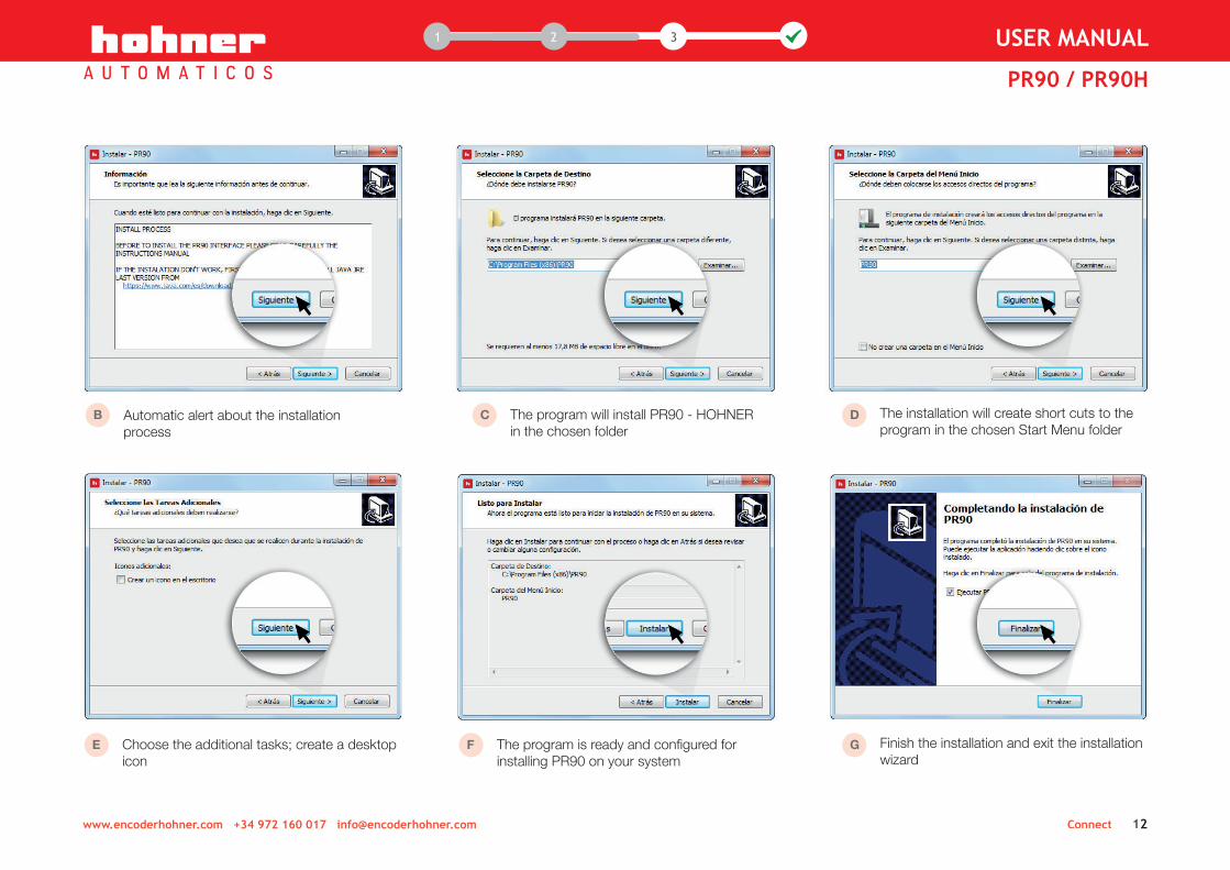
B Automatic alert about the installation process
C The program will install PR90 - HOHNER in the chosen folder
D The installation will create short cuts to the program in the chosen Start Menu folder
E Choose the additional tasks; create a desktop icon
F The program is ready and configured for installing PR90 on your system
G Finish the installation and exit the installation wizard
Connect 12www.encoderhohner.com +34 972 160 017 [email protected]
1 1 32 USER MANUAL
PR90 / PR90H

Open the "Communication Port" menu on the interface and choose the corresponding communications port (COMX), where the encoder is connected.
Once chosen, click on the button Connect in the upper bar. In approximately 2 seconds the programming interface will fill out with the programming and monitoring screens.
3.1configure theCOM port
menu on the interface and choose the corresponding A
, where the encoder is connected.B
Once chosen, click on the button Connect in the upper bar. In approximately 2 seconds the C
A B
Step 3: Run the programming software
C
If an error message appears: 1. Close the programming software2. Disconnect the uUSB/USB cable, and connect it again.3. Run the programming software, click on "Refresh" and then choose the
port where the PR90 is connected from the drop-down menu. port where the PR90 is connected from the drop-down menu. B
Connect 13www.encoderhohner.com +34 972 160 017 [email protected]
1 1 32 USER MANUAL
PR90 / PR90H

program
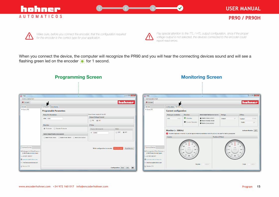
When you connect the device, the computer will recognize the PR90 and you will hear the connecting devices sound and will see a flashing green led on the encoder for 1 second.
Program 15www.encoderhohner.com +34 972 160 017 [email protected]
1 1 32 USER MANUAL
PR90 / PR90H
Pay special attention to the TTL / HTL output configuration, since if the proper voltage output is not selected, the devices connected to the encoder could report read errors.
Make sure, before you connect the encoder, that the configuration required for the encoder is the correct type for your application.
Monitoring Screen Programming Screen

Programming Screen
The configurable parameters are:
Enter the desired number of pulses. The program detects automatically the PPR value and alerts you with red message "Incorrect PPR" if it is not a valid value.
Pulses per revolution (PPR)from 1 to 65.536 PPR
A
Program 16www.encoderhohner.com +34 972 160 017 [email protected]
1 12 3 USER MANUAL
PR90 / PR90H
BOutput
typeTTL (RS422 5Vpp.
Differential)
HTL (Push-Pull 11~30Vpp. Differential)
This output can be programmed regardless of input voltage.
The PR90 encoder considers TTL from 4.5 to 10Vdc and HTL from 11 to 30 Vdc. If input values are below the HTL limit, the PR90 encoder will automatically switch output to TTL.
When required, select one of the output channels to switch the differential output (channel A: from A to nA, nA to A).
Switch output polarity
channel by channelA / B / Z
D
Reference signal position (Z)
0º to 360º
This setting will move the starting point for electrical connection to the mechanical start point, according to the selected mechanical degrees.
A and B channel synchronization will be maintained at all times.
FE
Reference signal width (Index, Z, 0)90º (synchronized with A and B) 180º (synchronized with A)
Rotationdirection
C
CW channel A leads B(view from the shaft, shaft rotating clockwise)
CCW channel B leads A (view from the shaft, shaft rotating counterclockwise
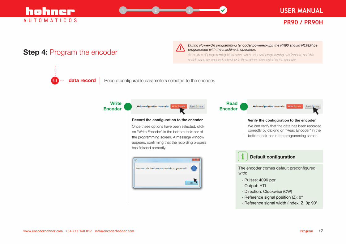
Default configuration
The encoder comes default preconfigured with:
- Pulses: 4096 ppr- Output: HTL- Direction: Clockwise (CW)- Reference signal position (Z): 0º- Reference signal width (Índex, Z, 0): 90º
During Power-On programming (encoder powered-up), the PR90 should NEVER be programmed with the machine in operation.
At the time of programming information can be lost until programming has finished, and this could cause unexpected behaviour in the machine connected to the encoder.
Program 17www.encoderhohner.com +34 972 160 017 [email protected]
1 12 3 USER MANUAL
PR90 / PR90H
Record the configuration to the encoder
Once these options have been selected, click on "Write Encoder" in the bottom task-bar of the programming screen. A message window appears, confirming that the recording process has finished correctly.
WriteEncoder
Record configurable parameters selected to the encoder.4.1 data record
Step 4: Program the encoder
Verify the configuration to the encoder
We can verify that the data has been recorded correctly by clicking on "Read Encoder" in the bottom task-bar in the programming screen.
ReadEncoder

Program 18www.encoderhohner.com +34 972 160 017 [email protected]
1 12 3 USER MANUAL
PR90 / PR90H
4.2configuration options Save/Load
Also you can Save/Load the programming parameters to use them whenever you want without having to repeat the entire selection process. The saved settings are stored in a selectable list and may be loaded as detailed below:
Save
Load
Export/Import configuration
- Export encoder configuration in external text document- Export all saved configurations in external text documents- Import encoder configuration previously exported
> >
>
>
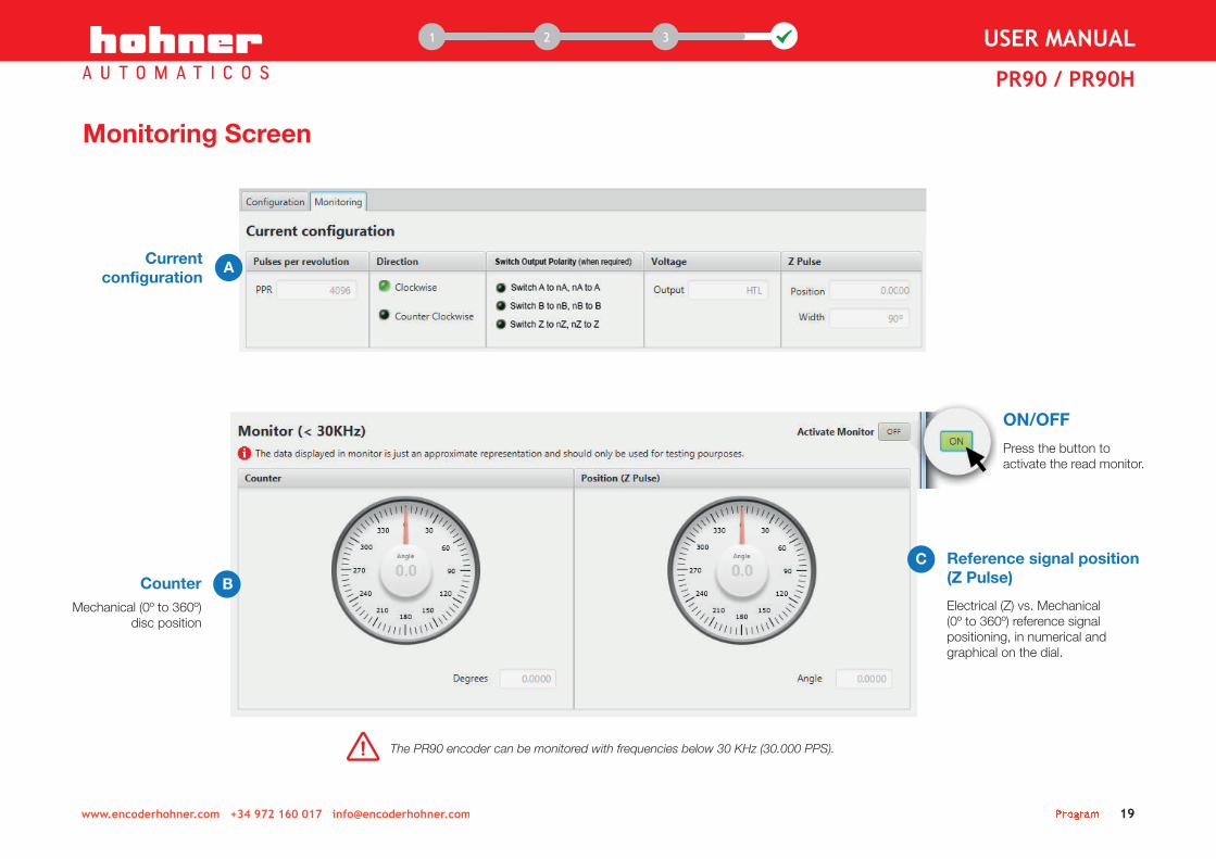
Monitoring Screen
C Reference signal position (Z Pulse)
Electrical (Z) vs. Mechanical (0º to 360º) reference signal positioning, in numerical and graphical on the dial.
ON/OFF
Press the button to activate the read monitor.
Program 19www.encoderhohner.com +34 972 160 017 [email protected]
1 12 3 USER MANUAL
PR90 / PR90H
The PR90 encoder can be monitored with frequencies below 30 KHz (30.000 PPS).
CounterMechanical (0º to 360º)
disc position
B
Current configuration
A
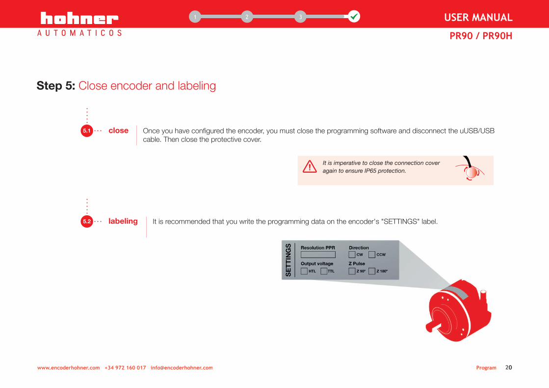
It is imperative to close the connection cover again to ensure IP65 protection.
1 12 3 USER MANUAL
PR90 / PR90H
Program 20www.encoderhohner.com +34 972 160 017 [email protected]
Once you have configured the encoder, you must close the programming software and disconnect the uUSB/USB cable. Then close the protective cover.
5.1 close
Step 5: Close encoder and labeling
It is recommended that you write the programming data on the encoder's "SETTINGS" label. 5.2 labeling
1 12 3 USER MANUAL
PR90 / PR90H
Program 21www.encoderhohner.com +34 972 160 017 [email protected]
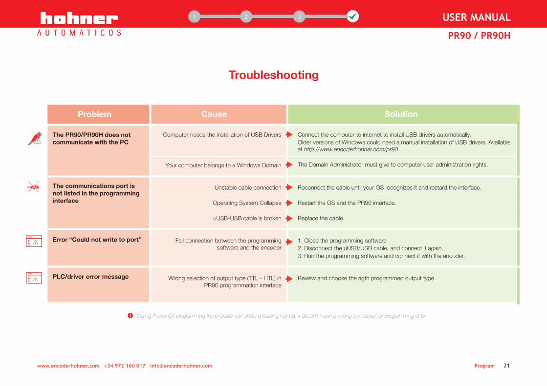
Troubleshooting
The PR90/PR90H does not communicate with the PC
Computer needs the installation of USB Drivers
Your computer belongs to a Windows Domain
Unstable cable connection
Operating System Collapse
uUSB-USB cable is broken
Fail connection between the programming software and the encoder
Wrong selection of output type (TTL - HTL) in PR90 programmation interface
Connect the computer to internet to install USB drivers automatically.Older versions of Windows could need a manual installation of USB drivers. Available at http://www.encoderhohner.com/pr90
The Domain Administrator must give to computer user administration rights.
Reconnect the cable until your OS recognizes it and restard the interface.
Restart the OS and the PR90 interface.
Replace the cable.
1. Close the programming software2. Disconnect the uUSB/USB cable, and connect it again.3. Run the programming software and connect it with the encoder.
Review and choose the rigth programmed output type.
Problem Cause Solution
The communications port is not listed in the programming interface
Error “Could not write to port”
PLC/driver error message
During Power-Off programming the encoder can show a flashing red led. It doesn’t mean a wrong connection or programming error.

Program 22
Considerations
Differentiated earth line
The equipment is absolutely shielded against external influences, electromagnetic fields and discharges. Even so, it is advisable to establish a differentiated earthing circuit. Branched earthing distribution.
Connectivity
Each differential output channel is identified by the colour of the wires, which plug directly into the differential PLC or Driver inputs. In order to preserve the quality of the signal, this equipment must be mounted on differential resistive loads.
In case of confusion in the connection, this can be corrected without need for disconnection, through the graphical programming interface.
Power Supply
This incremental encoder allows you to work at any voltage from 5 to 30Vdc without the need for any change or adjustment. However, you should pay attention to the polarity of the Vdc connection.
It is recommended in all instances to use a power supply that support loads in excess of 2 Amp., to ensure a very low power impedance and therefore better signal quality and the power supply correct start-up.
www.encoderhohner.com +34 972 160 017 [email protected]
1 12 3 USER MANUAL
PR90 / PR90H
PR90 - X X X - PR90 - X X X - CPR90 - X X X - CPR90 - X X X - C
1. Ø10x20mm2. Ø 6x10mm
1. Helicoidal cable2. M12 8p connector3. M23 12p connector
SHAFT
CONFIGURABLE OPTIONS
CONNECTION
1. None3. 90.11025. 90.1005
FLANGE
C. AA+BB+00~ ~ ~ C. 1...65536 PPR
C. HTL - TTL
Reference
PR90H - X X X - PR90H - X X X - CPR90H - X X X - CPR90H - X X X - C
2. Frontal clamp 1. Helicoidal cable2. M12 8p connector3. M23 12p connector
MECHANICAL OPT.
CONFIGURABLE OPTIONS
CONNECTION
1. Ø10mm2. Ø12mm3. Ø14mm
HOLLOW SHAFT
C. AA+BB+00~ ~ ~ C. 1...65536 PPR
C. HTL - TTL


DO
C.E
NC
I.PR
90X.
M.0
02 |
07/1
5
Prolongació c/ Sant Francesc, s/n17400 Breda (Girona) Spain
Tel. (00 34) 972 160 017Fax (00 34) 972 160 230


![Car Alarms & Smoke Alarms [Monitorama]](https://static.fdocuments.us/doc/165x107/54b6cdf94a7959d84d8b45a5/car-alarms-smoke-alarms-monitorama.jpg)