Manual (Part 1) USA - Amazon Simple Storage Service · ♦ mz-24 PRO User’s Manual (Part 1) ......
34
Manual (Part 1) mz-24 PRO 12 Channel HoTT 2.4 GHz Transmitter No. S1006.PRO and S1006.PRO.S USA
Transcript of Manual (Part 1) USA - Amazon Simple Storage Service · ♦ mz-24 PRO User’s Manual (Part 1) ......

Manual (Part 1)
mz-24 PRO 12 Channel HoTT 2.4 GHz Transmitter No. S1006.PRO and S1006.PRO.S
USA

2 / 34 S1006.PRO_mz-24_PRO_EN USA
INNOVATION & TECHNOLOGY
Contents Contents ................................................................................ 2
Introduction .................................................. 4 Programming Manual (Part 2) ...................... 4
Service Locations ................................................................... 4 Intended Use ......................................................................... 5
Target Group ................................................. 5 Package Content .................................................................... 5 Technical Data ....................................................................... 6 Symbols Explication ............................................................... 6 Transmitter Description ......................................................... 7
Transmitter Control Elements ...................... 7 Neck-Strap Attachment ................................ 8 Transmitter Back Side Connections .............. 8
Data Port ............................................... 8 Audio Port ............................................. 8 Mini-SD Card Slot .................................. 8 Mini-USB Connection ........................... 9 DSC Port ................................................ 9 Charging Port ........................................ 9
Transmitter Power Supply .......................... 10 Removing Transmitter Battery ........... 10 Inserting Transmitter Battery ............. 10
Charging Transmitter Battery ..................... 10 Using an external charger ................... 11 Using an AC Adapter ........................... 11 Charging Socket Polarity ..................... 11 Battery Use-time ................................ 11
Data Recording and Saving ......................... 12 Transmitter Setup ................................................................ 13
Turning on the Transmitter ........................ 13 Mz-24 PRO menus ...................................... 13
BASE .................................................... 14 FUNCTION ........................................... 14 SYSTEM ............................................... 15 TELEMETRY ......................................... 15
First-time Model Setup ............................... 15 D/R and EXP Setup .............................. 22 CTL and SYM Option ........................... 23
Binding ........................................................ 23 GR-12L Receiver .................................. 24 GR-16L Receiver .................................. 24 Transmitter ......................................... 24 Bind Procedure ................................... 24
Menu Functions ................................................................... 25 Keypad ........................................................ 25
Adjust Buttons (Left of Display) .......... 25 Select Buttons (Right of Display) ........ 25
Digital Trim .................................................. 25 Display Screen ............................................. 26

S1006.PRO_mz-24_PRO_EN USA_V1 3 / 34
INNOVATION & TECHNOLOGY
Operation............................................ 26 Active/Inactive Icons .......................... 26 Lock Screen ......................................... 26 Display Symbols .................................. 27
Stick Adjustment ......................................... 28 Stick Length Adjustment ............................. 28
Firmware Update ................................................................. 29 Transmitter software update...................... 29
Safety Notes ........................................................................ 30 Transmitter Safety ...................................... 30 Battery Safety ............................................. 31
LiPo Battery Charging Instructions ..... 31 LiPo Battery Storage and Safety Notes .................................................. 32
Declaration of Conformity .................................................... 32 Disposal ............................................................................... 32 Care and Maintenance ......................................................... 32 Warranty Certificate ............................................................ 33

4 / 34 S1006.PRO_mz-24_PRO_EN USA
INNOVATION & TECHNOLOGY
Introduction Thank you for purchasing the Graupner mz-24 PRO HoTT radio! The mz-24 PRO has been specially developed for the professional RC user who require programming flexibility and hardware reliability to address the ever-changing needs of model aviation. The mz-24 PRO incorporates many functions and enhancements requested by our users and team pilots. The mz-24 PRO radio has many new features and added functionality. If you have used our mz-24 radio in the past, you should have no difficulties adapting to the new user interface. If you are a new user, make sure to review this manual carefully. Due to technical changes, the information in this manual may be changed at any time without prior notice. Periodically check our website, www.graupnerusa.com for the most recent updates to the manual and firmware. Note This manual is part of the product. It contains important information concerning operation and handling. Keep these instructions for future reference. Please pass on to future owners.
Programming Manual (Part 2) This manual is comprised of two parts. The User’s Manual (Part 1) is included in the product's package content. The Programming Manual (Part 2) is located on the Downloads page at www.graupnerusa.com.
Service Locations Graupner USA – OPENHOBBY LLC 3941 Park Dr., Suite 20-571 El Dorado Hills, CA 95762 United States Phone: (855) 572-4746 x2 Hours: Mon – Fri 9:00am – 4:00pm PST Email: [email protected] Online Support: www.graupnerusa.com Forums: www.rcgroups.com/graupner-openhobby-874/

S1006.PRO_mz-24_PRO_EN USA_V1 5 / 34
INNOVATION & TECHNOLOGY
Intended Use This remote-control system is intended be used for the purpose specified by the manufacturer for operation of remote control models without passengers. Any other type of use is prohibited and may damage the system and cause significant property damage and/or personal injury. Improper use is not covered by this product’s warranty. Read through this entire manual before you attempt to install or use the transmitter. Graupner continuously enhances and updates its products and reserves the right to change its products, technology, user manuals and equipment at any time without prior notice.
Target Group This product is not a toy. It is not suitable for children under 14 years old. The operation of this product must be performed by experienced modelers. If you do not have sufficient knowledge about operating radio-controlled models, please contact an experienced modeler or a model club.
Package Content ♦ Transmitter mz-24 PRO HoTT ♦ 5000 mAh LiPo Transmitter battery ♦ Battery charger ♦ Receivers, 1 x GR-16L, 2 x GR-12L ♦ USB Adapter/Interface ♦ USB cable ♦ Adapter cable ♦ Transmitter neck strap ♦ Stylus ♦ mz-24 PRO User’s Manual (Part 1) ♦ Micro SD card ♦ Micro SD card adapter ♦ Transport case
The Programming Manual (Part 2) can be found on the Downloads section or product page at www.graupnerusa.com.
6 / 34 S1006.PRO_mz-24_PRO_EN USA
INNOVATION & TECHNOLOGY
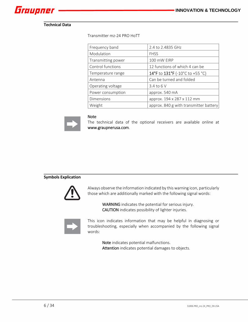
Technical Data Transmitter mz-24 PRO HoTT Frequency band 2.4 to 2.4835 GHz Modulation FHSS Transmitting power 100 mW EIRP Control functions 12 functions of which 4 can be
Temperature range 14°F to 131°F (-10°C to +55 °C) Antenna Can be turned and folded Operating voltage 3.4 to 6 V Power consumption approx. 540 mA Dimensions approx. 194 x 287 x 112 mm Weight approx. 840 g with transmitter battery
Note The technical data of the optional receivers are available online at www.graupnerusa.com.
Symbols Explication Always observe the information indicated by this warning icon, particularly those which are additionally marked with the following signal words:
WARNING indicates the potential for serious injury. CAUTION indicates possibility of lighter injuries.
This icon indicates information that may be helpful in diagnosing or troubleshooting, especially when accompanied by the following signal words:
Note indicates potential malfunctions. Attention indicates potential damages to objects.

S1006.PRO_mz-24_PRO_EN USA_V1 7 / 34
INNOVATION & TECHNOLOGY
Transmitter Description
Transmitter Control Elements
1 Antenna 2 Proportional dial DV3 3 INC/DEC buttons DT2 4 Switch SW 3 5 Proportional dial DV4 6 Switch SW 4 7 Switch SW 8 8 Switch SW 7 9 Right control stick 10 Alternative adjusting buttons 11 ENTER button 12 Trim 13 On/off switch
14 ESC button 15 Alternative selection buttons 16 Left control stick 17 Switch SW 5 18 Switch SW 6 19 Switch SW 1 20 Proportional dial DV1 21 Switch SW 2 22 INC/DEC buttons DT1 23 Proportional dial DV2 24 Neck-strap Eyehook 25 Switch SL2 26 Switch SL1
1
2
3 4 5 6
7 8
23
22 21 20
19 18
17
16 15 14 12 13 12 11 10 9 24
25 26

8 / 34 S1006.PRO_mz-24_PRO_EN USA
INNOVATION & TECHNOLOGY
Neck-Strap Attachment The Neck-Strap Attachment arm is located on the front of the transmitter above the power button.
Transmitter Back Side Connections
Data Port
Use the data port to connect the optional Smart Box P/N 33700 or Bluetooth adapter P/N S8351.
Audio Port
Use the audio port to plug-in ear phones, ear buds or headphones. Both acoustic signals and voice messages are emitted through this interface. Control the volume by going to the Etc. Set submenu of the SYSTEM menu where you can adjust the Voice Volume and Vario Volume field. Press the field to highlight and increase/decrease the value by pressing INC or DEC buttons to the right. Return the value to its default setting by pressing RES.
Mini-SD Card Slot
Use the mini-SD card slot for a compatible micro SD memory card: 2 GB and micro SDHC up to 32 GB. Recommended: standard memory card with a storage capacity of 4 GB. The included memory card is ready for use as soon as the transmitter is switched on.
Inserting and removing the memory card step by step: 1. Switch off the transmitter. 2. The memory card slot is located over the battery case under
the back side cover of the transmitter. 3. To insert: Push the SD card as deep into the slot until the
internal spring clicks it into place. 4. To remove: Push the SD card gently. The internal spring will
unlock and pop the card out slightly. It is now safe to remove. Refer to the Data Recording and Saving section for more information on using the memory card.

S1006.PRO_mz-24_PRO_EN USA_V1 9 / 34
INNOVATION & TECHNOLOGY
Mini-USB Connection Note The mini-USB port is not suitable for flight simulator connection and will not charge the radio. Use the Mini-USB Connection port to connect the transmitter to a PC for firmware updates. The appropriate software and USB drivers needed to perform this task can be found on the Downloads page at www.graupnerusa.com.
DSC Port
Use the DSC port to connect a DSC cable for flight simulator or wired T/S (teacher/student) systems. To enter DSC (Direct Servo Control) Mode or change the base display, go to the BASE menu and press the TX ctl icon to bring up the Transmitter Control submenu. The DSC Output controls are at the bottom of the screen. Refer to Programming Manual (Part 2) for additional information on programming the DSC.
DSC connection step by step: 1. Switch off the transmitter. 2. The DSC port is located beneath the battery case. Insert the
end of the DSC cable into the DSC port. 3. Switch the transmitter on.
ATTENTION! Electrostatic discharge can destroy the transmitter when connected to a computer via the DSC cable.
Charging Port
Use the Charging Port to safely charge the transmitter battery using the supplied plug-in charger. The maximum charge current is 1.5 A. Refer to the Charging the Transmitter Battery section for additional information. Note USE THE SUPPLIED GRAUPNER PLUG-IN CHARGER ONLY. Serious damage can occur if the batteries are charged using products made by other manufacturers.
10 / 34 S1006.PRO_mz-24_PRO_EN USA
INNOVATION & TECHNOLOGY
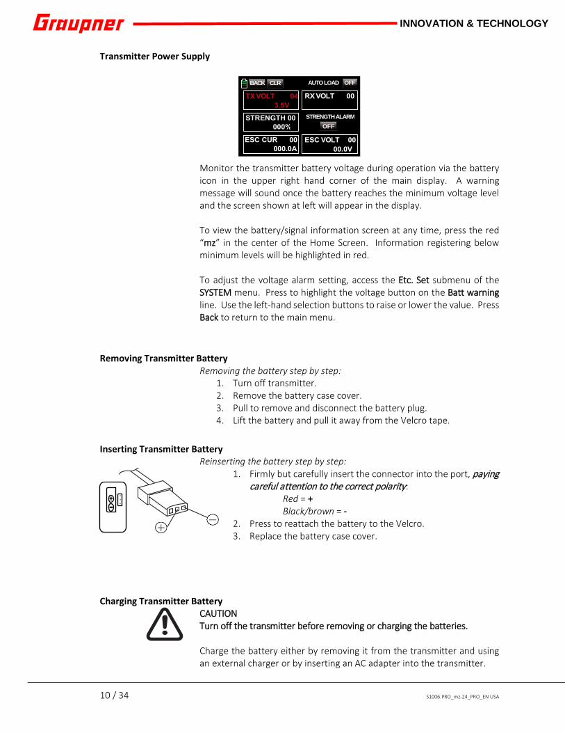
Transmitter Power Supply Monitor the transmitter battery voltage during operation via the battery icon in the upper right hand corner of the main display. A warning message will sound once the battery reaches the minimum voltage level and the screen shown at left will appear in the display. To view the battery/signal information screen at any time, press the red “mz” in the center of the Home Screen. Information registering below minimum levels will be highlighted in red. To adjust the voltage alarm setting, access the Etc. Set submenu of the SYSTEM menu. Press to highlight the voltage button on the Batt warning line. Use the left-hand selection buttons to raise or lower the value. Press Back to return to the main menu.
Removing Transmitter Battery
Removing the battery step by step: 1. Turn off transmitter. 2. Remove the battery case cover. 3. Pull to remove and disconnect the battery plug. 4. Lift the battery and pull it away from the Velcro tape.
Inserting Transmitter Battery
Reinserting the battery step by step: 1. Firmly but carefully insert the connector into the port, paying
careful attention to the correct polarity: Red = + Black/brown = -
2. Press to reattach the battery to the Velcro. 3. Replace the battery case cover.
Charging Transmitter Battery CAUTION Turn off the transmitter before removing or charging the batteries. Charge the battery either by removing it from the transmitter and using an external charger or by inserting an AC adapter into the transmitter.
BACK CLR AUTO LOAD OFF
STRENGTH ALARM OFF
S1006.PRO_mz-24_PRO_EN USA_V1 11 / 34
INNOVATION & TECHNOLOGY
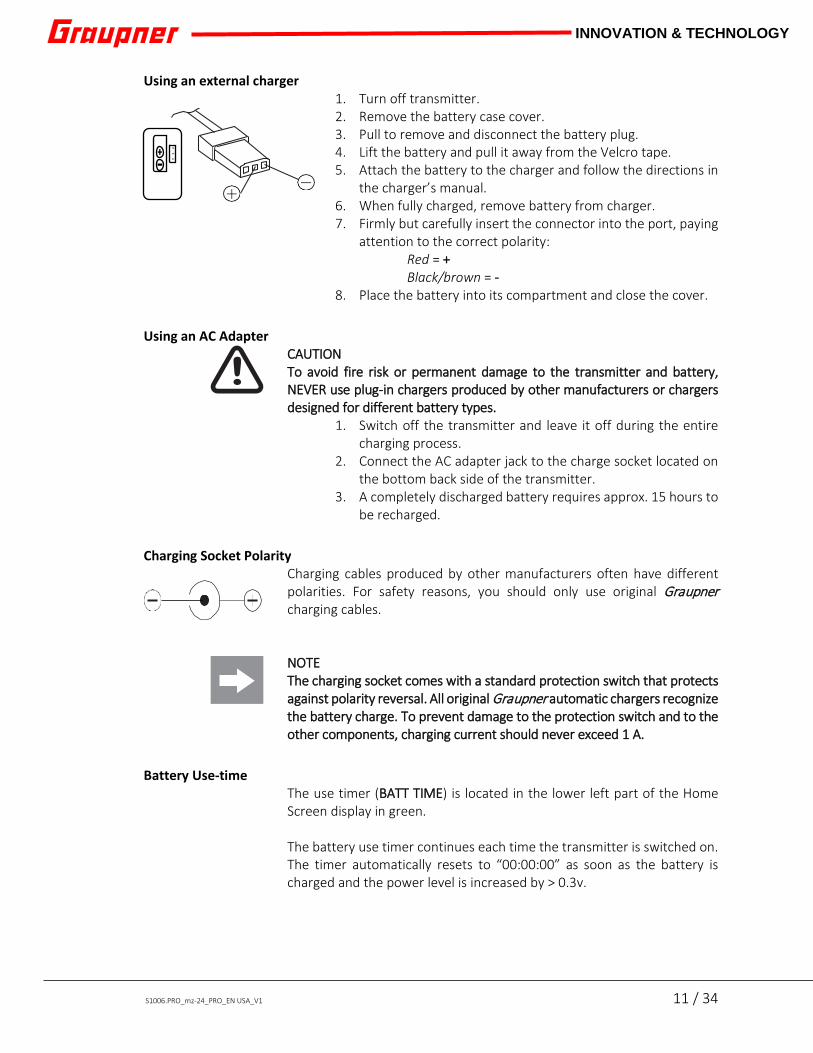
Using an external charger 1. Turn off transmitter. 2. Remove the battery case cover. 3. Pull to remove and disconnect the battery plug. 4. Lift the battery and pull it away from the Velcro tape. 5. Attach the battery to the charger and follow the directions in
the charger’s manual. 6. When fully charged, remove battery from charger. 7. Firmly but carefully insert the connector into the port, paying
attention to the correct polarity: Red = + Black/brown = -
8. Place the battery into its compartment and close the cover. Using an AC Adapter
CAUTION To avoid fire risk or permanent damage to the transmitter and battery, NEVER use plug-in chargers produced by other manufacturers or chargers designed for different battery types.
1. Switch off the transmitter and leave it off during the entire charging process.
2. Connect the AC adapter jack to the charge socket located on the bottom back side of the transmitter.
3. A completely discharged battery requires approx. 15 hours to be recharged.
Charging Socket Polarity
Charging cables produced by other manufacturers often have different polarities. For safety reasons, you should only use original Graupner charging cables. NOTE The charging socket comes with a standard protection switch that protects against polarity reversal. All original Graupner automatic chargers recognize the battery charge. To prevent damage to the protection switch and to the other components, charging current should never exceed 1 A.
Battery Use-time
The use timer (BATT TIME) is located in the lower left part of the Home Screen display in green. The battery use timer continues each time the transmitter is switched on. The timer automatically resets to “00:00:00” as soon as the battery is charged and the power level is increased by > 0.3v.

12 / 34 S1006.PRO_mz-24_PRO_EN USA
INNOVATION & TECHNOLOGY
Data Recording and Saving Flight data logging is a powerful way to analyze flight performance and flight information generated during flight from the attached telemetry modules in your model. The data recording in the SD card is linked to the flight timer. When the flight timer is started, the flight data recording starts and stops when the flight timer is stopped. Refer to the Timer section of the Programmer Manual (Part 2) for additional information on setting the timer.
Data Recording and Saving step by step: 1. Switch off the transmitter and insert the SD card into the slot
on the back side. Switch the transmitter back on. The card is ready for use. The SD card icon will highlight blue on the General Settings display screen.
2. Once installed, the SD card will create empty folders called "Models". Data is writing to the memory card when the SD card icon blinks.
3. Log files are saved in subfolders called "Modelname". Files are named using the following scheme: 0001_year-month-day.bin, 0002_year-month-day.bin, etc. An unnamed file will appear in the subfolders as "NoName".
Export data to a compatible computer using the Firmware Update Studio found on the Downloads page at www.graupnerusa.com. Insert the memory card into a PC via the supplied memory card reader. Using the Firmware Update Studio program and the File Log View menu option, load the corresponding model data file and follow the screen instructions.

S1006.PRO_mz-24_PRO_EN USA_V1 13 / 34
INNOVATION & TECHNOLOGY
Transmitter Setup
Turning on the Transmitter Whenever the transmitter is turned on, you will see a Warning Window. If a receiver is not bound to the transmitter a warning screen appears. Select SET to open the Bind Function screen. If a receiver is bound to the transmitter, another warning screen appears. Select ON or OFF to turn on or off the RF. On the Home Screen, locate the RF icon. If the RF is off, the icon is greyed out. If the RF is on indicating that the TX is bound to an RX, the icon is highlighted blue and TX and RX will appear on each side of the icon. If the receiver is active, bar graphs will appear indicating the transmitter (TX) and receiver (RX) signal strength.
Mz-24 PRO menus
There are four icons on the lower right hand corner that allow you direct access to each of the radio functions menus
Warning
Thr.HOLD Thr.CUT
Thr.POS PHASE
SET
Warning
Thr.HOLD Thr.CUT
Thr.POS PHASE
TX
RX 05.5V 4.2V
0:01:23
M- 1
MODEL NAME 1
mz
000:00.0 000:00.0
PHASE 1
Fail Safe not set No receiver bound to TX
Fail Safe not set Please select RF ON/OFF
Normal signal
ON OFF

14 / 34 S1006.PRO_mz-24_PRO_EN USA
INNOVATION & TECHNOLOGY
BASE The BASE menu provides access to all the basic functions to setup a model. Here you can setup a new mode, bind your receivers and fine tune your settings like reversing servo’s channel assignments, telemetry, voice notifications and more.
FUNCTION
After setting up your model in the BASE you can enhance your model settings in the FUNCTION menu. Here you create your flight phases, dual rates, flap settings, logical switches and anything else that has to with enhancing your models performance.
Airplane Functions
Helicopter Functions
S1006.PRO_mz-24_PRO_EN USA_V1 15 / 34
INNOVATION & TECHNOLOGY
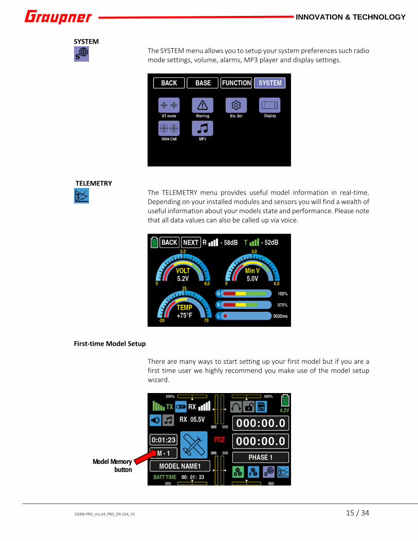
SYSTEM The SYSTEM menu allows you to setup your system preferences such radio mode settings, volume, alarms, MP3 player and display settings.
TELEMETRY
The TELEMETRY menu provides useful model information in real-time. Depending on your installed modules and sensors you will find a wealth of useful information about your models state and performance. Please note that all data values can also be called up via voice.
First-time Model Setup
There are many ways to start setting up your first model but if you are a first time user we highly recommend you make use of the model setup wizard.
Model Memory button

16 / 34 S1006.PRO_mz-24_PRO_EN USA
INNOVATION & TECHNOLOGY
Press the Model Memory button on the Home Screen display to bring up the Model Sel submenu:
Highlight the MODEL NAME field by pressing the button next to the line number. Press the NEW button along the right hand side of the screen. A popup menu will appear with three options. NO - cancels the process, MAN. – opens the manual setup screen, WIZ. – opens the wizard setup screen.
First-time users: select WIZ. The wizard setup screen will guide users through all the required settings for the new model. Type the name of the new model. Press CAPS, NUM or SPECIAL for additional character choices. For spaces, deleting and entering, use the following buttons on the main keyboard:
[ _ ] = space [ << ] = clear [ < ] = delete [ = ] = enter
Select
_

S1006.PRO_mz-24_PRO_EN USA_V1 17 / 34
INNOVATION & TECHNOLOGY
Press [ = ] to enter the new name into the New Model Name field at left:
Select the WIZ. button to advance to the next screen.
Select the model type by pressing the icon. The following images correlate to the AIRPLANE mode:
Choose the wing type and number of servos used for ailerons and flaps. (Press the NORMAL button to change the wing type to DELTA.) Select the appropriate aileron/flap button that corresponds with the number of aileron and flap channels needed for the model. If you use a Y-cable for your ailerons and flaps, then the appropriate choice would be the (1A1F) button, and so on. (Refer to the icons or the Model Type menu for servo connection details.) For this example, the 2AILE2FLAP button was selected.
Note: servo channels are defined on each icon on this display
screen.
_

18 / 34 S1006.PRO_mz-24_PRO_EN USA
INNOVATION & TECHNOLOGY
A tail configuration screen appears.
Select the appropriate icon for the model (refer to the model’s manual for tail configuration information). For this example, the NORMAL button was selected. The power system screen appears.
Select the appropriate icon for the model’s power system. The REV/SUB menu appears.
Use this screen to reverse the servos or make fine sub trim adjustments.
S1006.PRO_mz-24_PRO_EN USA_V1 19 / 34
INNOVATION & TECHNOLOGY
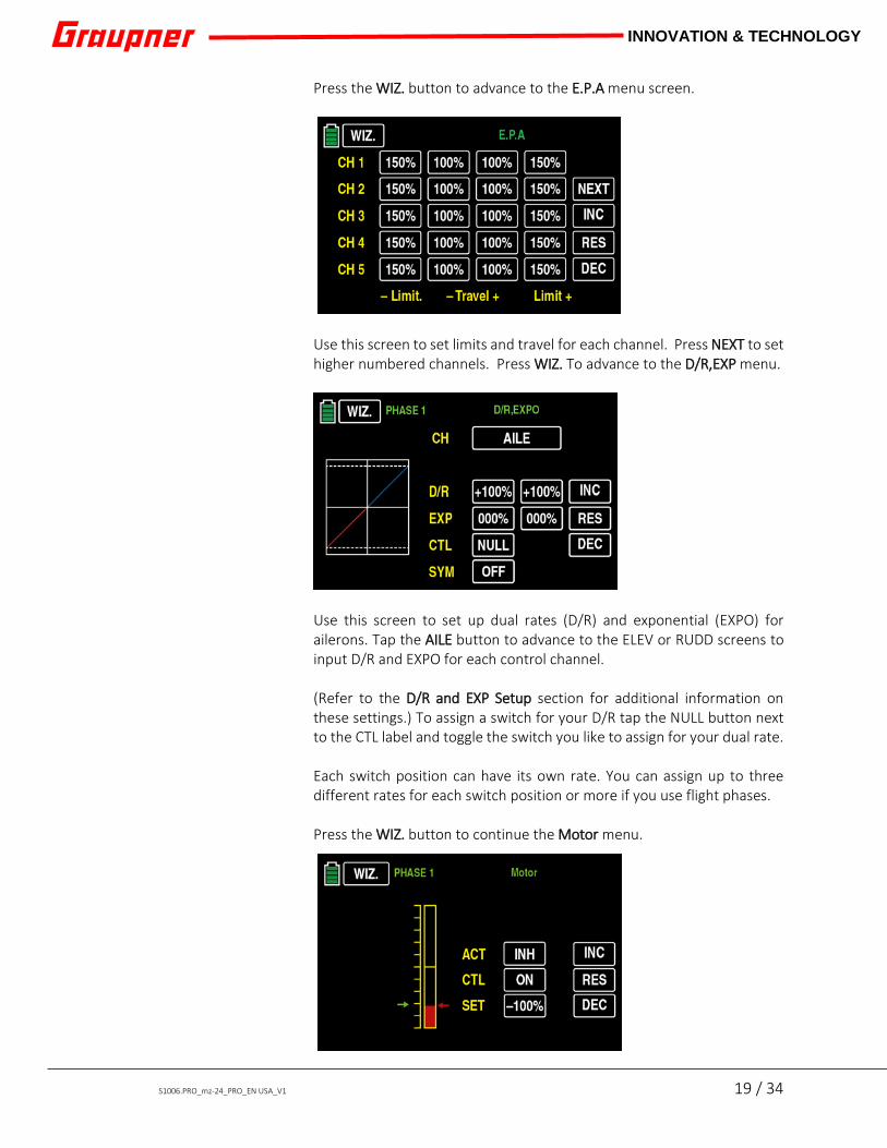
Press the WIZ. button to advance to the E.P.A menu screen.
Use this screen to set limits and travel for each channel. Press NEXT to set higher numbered channels. Press WIZ. To advance to the D/R,EXP menu.
Use this screen to set up dual rates (D/R) and exponential (EXPO) for ailerons. Tap the AILE button to advance to the ELEV or RUDD screens to input D/R and EXPO for each control channel. (Refer to the D/R and EXP Setup section for additional information on these settings.) To assign a switch for your D/R tap the NULL button next to the CTL label and toggle the switch you like to assign for your dual rate. Each switch position can have its own rate. You can assign up to three different rates for each switch position or more if you use flight phases. Press the WIZ. button to continue the Motor menu.

20 / 34 S1006.PRO_mz-24_PRO_EN USA
INNOVATION & TECHNOLOGY
Use this screen to set throttle cut. Throttle Cut is used to stop Nitro and Gas engines or to prevent accidental starting of an electric motor. Propellers are extremely dangerous: pilots can inadvertently move the throttle stick with the swipe of a hand, elbow, or by brushing against the pants leg while walking to retrieve an aircraft. Once stopped, nitro and gas engines are not likely to start up again, but electric motors can start spinning at any time. To add an extra level of safety, always set up a throttle cut on your transmitter.
This completes the basic setup of your airplane. Press the ENT button to return to the BASE menu screen.
To assign switches to other functions such as flaps or landing gear, select CTL Set in the BASE menu which will bring to where you can assign switches, controls and channel delays to any channel. The first screen shows the assignment of the main controls for your throttle (ST1), aileron (ST2), elevator (ST3) and rudder (ST4). Press the next button which will bring you the page where you can assign switches or proportional controls to any channel on your radio. Let setup a control for flaps by touching the CH5 button. A dialog will show that allows you to cancel the operation, clear a previously assigned switch, assign a logical switch or assign a new switch which is done by moving the control you want to use for your channel.

S1006.PRO_mz-24_PRO_EN USA_V1 21 / 34
INNOVATION & TECHNOLOGY
For this example, SW5 is assigned to flaps by toggling the switch on the radio to record it to CH5
CH5 which is your flap channel can now be operated with SW5. In most cases we would like to have the flaps move slowly into position to reduce sudden attitude changes which can be done with slowing them movement down a bit. Press NEXT twice which will bring you to the channel slow menu.
Add a delay for example of 1.2s on CH5 which will slow the movement of that channel with 1.2 seconds. If you want to see how any of the channels are responding to inputs press the SERVO button on the screen which will show the servo monitor screen. Move your controls to view an animated view of all of your channels. This concludes the basic setup of your model. You can assign additional switches or setup your fail safe and timers all done from the BASE menu. For more advanced options, you can go to the FUNCTION MENU where you can setup flight modes, dual/triple rates and more.

22 / 34 S1006.PRO_mz-24_PRO_EN USA
INNOVATION & TECHNOLOGY
D/R and EXP Setup Dual Rates (D/R) are used to change the aircraft’s response to stick movements. Beginners often over-control a model by moving the sticks too aggressively. Skilled pilots may want larger control movements while performing a 3D maneuvers, but smaller control movements during landing. Some pilots use EXP to reduce the sensitivity of the sticks in the center while having a full response as the sticks move away from center. For example: aileron throws have been reduced to 32% of maximum while exponential has been set to 20%, this means the ailerons will deflect up or down no more than 32% of their max deflection. Small stick movements in the center will produce smaller deflections than the same movement near the end of the stick’s travel. If the ailerons are set at 62% they will be capable of larger deflections while exponential set at 42% will make the stick feel mushy or less sensitive in the middle of the throw. To adjust the model’s response to stick movements, select the D/R,EXP submenu in the FUNCTION menu.
Press to highlight the percent buttons in the D/R or EXP. To raise or lower the values press either the left side adjust buttons or the INC (increase) or DEC (decrease) buttons on the display screen. Press RES to reset the fields to their default values. Make the same adjustments as necessary in the ELEV and RUDD screens by pressing the button in the CH line.
SERVO BACK

S1006.PRO_mz-24_PRO_EN USA_V1 23 / 34
INNOVATION & TECHNOLOGY
CTL and SYM Option CTL = control device. The control device can be assigned to any control on the transmitter: switch, slide, knob, or stick position. To activate the CTL function, press the NULL button in the CTL line. A popup window appears:
NO = cancel operation CLR = clear currently assigned control LOGIC = assign logical switch
To assign a control, simply move the desired switch to register the function. The pop-up screen will disappear and the assigned switch should appear in the field on the CTL line. Repeat the steps to assign a different switch. SYM = simultaneous. This functions allows both D/R,EXP value fields to be adjusted at the same time. Press the ON/OFF button on the SYM line to activate this function. Press any field on the D/R or EXP line and both buttons highlight blue. To raise or lower the values press either the left side adjust keys or the INC (increase) or DEC (decrease) buttons on the display screen. Press RES to reset the fields to their default values.
Binding Binding allows the transmitter and receiver to communicate and must be done before a model can be operated. The binding procedure differs between receiver types. NOTE To avoid feedback and connection malfunctions, make sure the transmitter antenna is at least 1 meter (3 feet) away from the receiver antenna. Binding will not work if the receiver power supply is too low. Note that all switched-on receivers previously bound to the transmitter enter fail safe mode while the transmitter is binding to a new receiver. THE BATTERY AND SERVO CONNECTION POLARITY ON THE GR-12 TYPE
BACK SERVO
Select
NO
CLR
LOGIC

24 / 34 S1006.PRO_mz-24_PRO_EN USA
INNOVATION & TECHNOLOGY
RECEIVERS ARE DIFFERENT FROM ALL OTHER GRAUPNER RECEIVERS. GR-12L Receiver
♦ When the receiver is not bound, the LED glows solid RED ♦ When bound, the LED flashes intermittently. ♦ When in bind mode, the LED is OFF and it only stays in binding
mode for a few seconds.
GR-16L Receiver ♦ When the receiver is not bound, the Red LED blinks slowly ♦ When bound, the LED glows solid green ♦ When in bind mode, the Green and Red LEDs are on and will
stay in bind mode for a few seconds.
Transmitter Start with transmitter and receiver off. (Always remove all propellers before starting the bind process.)
1. Turn on the transmitter, then the receiver 2. Go to the BASE menu and select the desired model 3. Select TX ctl
4. The BIND ON/OFF function is the first row of the menu. In the column RX1 there is a button labeled: OFF. (Or it will indicate the number of channels discovered in a previous bind; pressing the button will clear the previous bind)
Bind Procedure
1. Press and hold the set button on the receiver for about 3 seconds
2. Press the Bind button on the transmitter 3. The OFF will change to CHK momentarily 4. If the bind is successful, the number of receiver channels
will be displayed 5. If the bind is not successful, the Button will return to OFF
status Repeat the bind process until bind is successful. (It is all a matter of timing. Counting “one thousand one, one thousand two, one thousand three” will help with the timing.)
AUTOLOG 99sec
BIND ON/OFF TX OUT SET RF ON/OFF RANGE TEST DSC OUTPUT
RX1 RX2 OFF OFF
SET SET
PPM10 OFF
RF TYPE NORMAL OFF OFF
BACK
TX ctl
S1006.PRO_mz-24_PRO_EN USA_V1 25 / 34
INNOVATION & TECHNOLOGY
Menu Functions
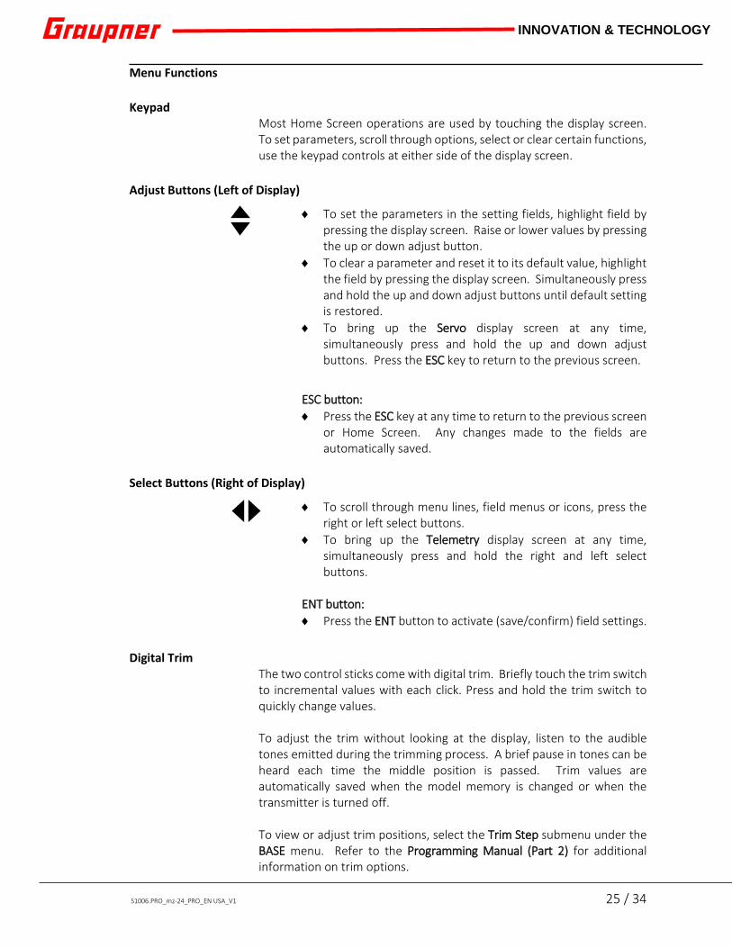
Keypad Most Home Screen operations are used by touching the display screen. To set parameters, scroll through options, select or clear certain functions, use the keypad controls at either side of the display screen.
Adjust Buttons (Left of Display)
♦ To set the parameters in the setting fields, highlight field by pressing the display screen. Raise or lower values by pressing the up or down adjust button.
♦ To clear a parameter and reset it to its default value, highlight the field by pressing the display screen. Simultaneously press and hold the up and down adjust buttons until default setting is restored.
♦ To bring up the Servo display screen at any time, simultaneously press and hold the up and down adjust buttons. Press the ESC key to return to the previous screen.
ESC button: ♦ Press the ESC key at any time to return to the previous screen
or Home Screen. Any changes made to the fields are automatically saved.
Select Buttons (Right of Display)
♦ To scroll through menu lines, field menus or icons, press the right or left select buttons.
♦ To bring up the Telemetry display screen at any time, simultaneously press and hold the right and left select buttons.
ENT button: ♦ Press the ENT button to activate (save/confirm) field settings.
Digital Trim
The two control sticks come with digital trim. Briefly touch the trim switch to incremental values with each click. Press and hold the trim switch to quickly change values. To adjust the trim without looking at the display, listen to the audible tones emitted during the trimming process. A brief pause in tones can be heard each time the middle position is passed. Trim values are automatically saved when the model memory is changed or when the transmitter is turned off. To view or adjust trim positions, select the Trim Step submenu under the BASE menu. Refer to the Programming Manual (Part 2) for additional information on trim options.

26 / 34 S1006.PRO_mz-24_PRO_EN USA
INNOVATION & TECHNOLOGY
Display Screen Operation
Operate the display screen by touching fields and icons with either a finger or the provided stylus.
Active/Inactive Icons Refer to the color of an icon to determine if its function is active or inactive:
Blue = active Gray = inactive
Lock Screen Lock any screen at any time by simultaneously pressing and holding the ESC and ENT keys. A warning tone will sound. If on the Home Screen display, the Screen Lock icon in the upper right hand corner changes from an unlocked gray icon to a locked blue icon. To unlock, simultaneously press and hold the ESC and ENT keys again until entry lock icon changes from the locked blue icon back to the grey unlocked icon and/or a warning tone sounds.

S1006.PRO_mz-24_PRO_EN USA_V1 27 / 34
INNOVATION & TECHNOLOGY
Display Symbols
1 Model operating time 2 MP3 Player icon 3 RF On/Off icon 4 Visual trim indicator for DV 2 5 Model type graphic
6 Visual trim indicator for DV 1
7 Visual trim indicator for DV 2 8 Timer 1 9 Timer 2 10 Visual trim indicator for DV 3 11 Transmitter battery voltage tri-color display 12 Model memory 13 Model name 14 Battery use timer 15 "mz" field. Press to open menu showing: transmitter/receiver battery voltage, ESC current/voltage,
signal strength and signal alarm.
16 Two visual trim indicators for each side 17 BASE menu icon 18 FUNCTION menu icon 19 SYSTEM menu icon 20 TELEMETRY display screen icon 21 Flight phase name
1 2 3 4 5 6 7 8 9 10 11
12 13 14 15 16 17 18 19 20 21

28 / 34 S1006.PRO_mz-24_PRO_EN USA
INNOVATION & TECHNOLOGY
Stick Adjustment All adjustments can be made on the back side of the transmitter without opening the transmitter case using a cross head screwdriver.
Battery Compartment Screwsets Two sets of screws can be reached through the battery compartment, one for each stick. Turn the top left screw (3) counterclockwise to disable the stick’s centering tension. Turn the bottom left screw (5) clockwise to increase the spring tension. Turn the bottom right screw (6) clockwise to disable the stick’s forward and back centering tension. Turn the top right screw (7) clockwise to increase the spring tension. Rubber Hand Grip Screwsets Remove the rubber hand grips to reveal two small black screws for each stick. Turn the outermost screws (1 and 10) clockwise to increase friction so the stick will stay in place. Turn the innermost screws (2 and 9) clockwise to increase detente friction Rubber Plug Screwsets Remove the small rubber plugs on either side of the battery compartment to adjust LEFT/RIGHT centering tension. Turn the screws (4 and 8) clockwise to increase centering tension.
Stick Length Adjustment To adjust the length of the stick, hold the bottom half of the knurled grip and loosen the connection by unscrewing the top half. Lengthen or shorten the stick by turning it up or down. To tighten, hold the bottom half of the grip and screw the two halves back together.

S1006.PRO_mz-24_PRO_EN USA_V1 29 / 34
INNOVATION & TECHNOLOGY
Firmware Update Transmitter firmware, programs, files and software required for updates are available for download at www.graupnerusa.com. Look for the Firmware Update Studio program in the download section. Use the USB port on the back of the transmitter to upload the updates. Note
♦ Compatible firmware is required for reliable communication between the HoTT components. All programs and files required for update are combined into a single file.
♦ The current firmware version can be found by using the firmware update studio program available on online at www.graupnerusa.com.
♦ Only operate your transmitter using the current software version. This information is also available at: www.graupnerusa.com.
♦ Before each update, always check or charge transmitter battery and save all model memories in case restoration is required.
♦ DO NOT disconnect the computer link during an update! Verify the link between the transmitter and computer is operational.
♦ After each update, check to make sure that the models function correctly.
Transmitter software update Update step by step directions:
1. Download the software package from the Internet and unpack it on your computer.
2. Switch on the transmitter. 3. Connect your transmitter to the PC using the supplied
USB cable. Plug one end of the cable into a free USB port on the computer and the other end to the USB port on the transmitter.
4. Refer to the instructions included in the software package for additional installation directions.

30 / 34 S1006.PRO_mz-24_PRO_EN USA
INNOVATION & TECHNOLOGY
Safety Notes These safety instructions are intended to protect this product, yourself and the safety of others. Please read this section very carefully before using this product!
♦ Check all relevant laws and regulations before using this remote control model. These laws and regulations must be observed in for the safety of yourself and others and may vary by state, region, or country.
♦ First-time users: carefully familiarize yourselves with this model’s functions and commands. Always exercise caution and operate this model responsibly.
♦ To avoid risk of suffocation, keep packaging materials away from babies and small children.
♦ Supervision by an experienced adult is required for children, persons mentally or physically handicapped, novices, or anyone not capable of safely using this product.
♦ Special liability insurance policies are mandatory for all device operations. If you already own a device, determine if the respective model is covered by your insurance.
♦ Protect all equipment from dust, dirt, moisture, vibration and excessive heat or cold. The models may only be operated remotely in normal outside temperatures ranging from 15°F to 130°F (-10°C to 55°C).
♦ To ensure safe operation, always perform a range test and functional test on the ground before you use your model!
♦ Maintain frequent updates of your HoTT components with the latest firmware version.
♦ Save the log file of the model after each use. Information in the log can help to diagnose technical failures, and be used to submit claims about performance.
♦ For additional questions or support, contact the Graupner USA Service Center, or an experienced user.
Transmitter Safety WARNING Rotating propellers can cause injury. To make sure the connected motors cannot accidentally start when programming the transmitter, turn the transmitter’s motor off, or detach the propellers. CAUTION Short-circuiting the transmitter sockets can create a fire hazard. Use only suitable connectors. Never change or modify the electronic components of the transmitter. Reconstruction and/or modification of the product is prohibited by law. Note Carefully pack the model and transmitter when transporting to protect from damages and excessive vibration.

S1006.PRO_mz-24_PRO_EN USA_V1 31 / 34
INNOVATION & TECHNOLOGY
Battery Safety CAUTION
♦ Protect batteries from dust, moisture, heat and vibrations. For use in dry locations only.
♦ Do not use damaged batteries. ♦ Batteries should not be altered, heated, burned, short-
circuited, incorrectly inserted, modified, soldered or welded.
♦ Batteries not handled properly may catch fire, explode, or cause irritation and burns. To extinguish a battery fire use either water, CO² or sand.
♦ Verify the charger being used is intended for the battery type and specifications. Only connect one battery at a time to the charger out-put.
♦ Only use batteries and cables with proper connectors and reverse polarity protection. Always verify polarity is correct.
♦ Charge batteries in a room outfitted with a smoke detector, on a non-flammable, heat-resistant and non-conductive surface. Keep away from combustible or highly flammable objects while charging. Always monitor batteries during the charging process.
♦ Keep ventilation slots clear and the charger uncovered during the charging process.
♦ Do not exceed the maximum quick-charging current specified for the respective cell type.
♦ Damaged or corroded batteries may leak an electrolyte that is caustic and should not be touched or come into contact with your skin or eyes. In case of emergency, rinse thoroughly with water and seek immediate medical attention.
♦ If a battery reaches temperatures above 140°F (60°C) while it is being charged, immediately stop charging and let the battery cool down to approximately 86° to 104°F (30 - 40°C).
♦ Never charge batteries that have already been charged, are hot or are not fully discharged. If a cell in a battery pack heats up following a quick-charge process, this may indicate a defective cell. Discard the battery immediately!
♦ Always fully recharge the battery prior to use. ♦ Store batteries in a cool, dry place. ♦ Dispose of batteries at the proper disposal or recycling
centers.
LiPo Battery Charging Instructions ♦ Only use specifically designed chargers/dischargers with
balancer connector to charge and discharge LiPo batteries.
♦ The white connector (cell count + 1 pole) is specially

32 / 34 S1006.PRO_mz-24_PRO_EN USA
INNOVATION & TECHNOLOGY
designed to connect a LiPo balancer or single-cell battery charger with a manual-cell balancer. Always charge the battery with the balancer connector.
LiPo Battery Storage and Safety Notes ♦ Store batteries in dry locations between temperatures of
41°C to 77°C (5°C to 25°C). ♦ LiPo batteries should be stored with a voltage of about
3.8V per cell. If the cell voltage falls below 3V, then the battery must be charged. Fully discharging or storing a battery with a cell voltage < 3V renders the battery useless.
♦ Exercise safety precautions when charging and transporting your LiPo batteries. Always use a safety bag.
Declaration of Conformity
FCC-SNL-36204410 Graupner/SJ declares that the product is conform to EU norms. EMV 2004/108/EC: EN 301 489-1 V1.9.2 EN 301 489-17 V2.1.1 EN 62479:2010 LVD 2006/95/EC: EN 60950-1 + A11 + A1 + A12 + A2:2013 R&TTE 1999/5/EC: EN 300 328 V1.8.1 EN 62311:2008
Disposal This symbol on the product, user manual or packaging indicates that this product must not be disposed of with other household waste. It must be disposed of or recycled at a facility that accepts electrical and electronic equipment. Materials are recyclable as marked. You are making an important contribution to environmental protection by recycling materials for reuse. Batteries and accumulators must be removed from the device and disposed of or recycled at a proper disposal centers. Contact local authorities for the appropriate facility in your area.
Care and Maintenance
S1006.PRO_mz-24_PRO_EN USA_V1 33 / 34
INNOVATION & TECHNOLOGY
The product does not need any maintenance. Always protect it against dust, dirt and moisture. Clean the product by lightly rubbing with a dry cloth. Do not use detergent!
Warranty Certificate Graupner USA – OPENHOBBY LLC at 3941 Park Drive Suite 20-571, El Dorado Hills, CA 95762 warranties this product from the date of purchase for a period of 24 months. The warranty applies only to the material or operational defects already existing when you purchased the item. Damage due to wear, overloading, incorrect accessories or improper handling are excluded from the warranty. The legal rights and claims are not affected by this warranty. Please check defects before making a claim or send the product. If the item is found to be free of defects, we may charge shipping and handling fees. The present construction or user manual is for informational purposes only and may be changed without prior notice. The current version can be found on the Internet at www.graupnerusa.com on the relevant product page. In addition, the company Graupner USA OPENHOBBY LLC assumes no responsibility or liability for any errors or inaccuracies that may appear in construction or operation manuals. No liability can be accepted for printing errors.
P

34 / 34 S1006.PRO_mz-24_PRO_EN USA
INNOVATION & TECHNOLOGY
Notes