
Manual Para USCC-1L2M
104
MICRO-SCREEN Features • A compact, modular optoelectronic safeguarding device for smaller light- to medium-duty production machinery • Choose Standard Series or V-Series emitters and receivers • Creates a synchronized, modulated infrared light screen in 15 sizes from 100 mm to 1.8 m (4" to 6') high • Full-featured Muting function including: - Input from two or four Muting Devices - Selectable monitored Mute Lamp output - Selectable Backdoor Timer - Override inputs - Selectable directional muting capability • Emergency stop input • Selectable External Device Monitoring (EDM) • Control-reliable redundant output relays • Uses 115/230V ac or 24V dc power • Dual two-digit Diagnostic Displays indicate Light Screen and System status, including number of channels blocked • LEDs on control box and receiver give system status and emitter/receiver alignment indications • Easily configured one- or two-beam floating blanking • Two models of heavy-duty control boxes available: - USCC-1L2M without fixed blanking - USCC-2L2M with fixed blanking MICRO-SCREEN ® Instruction Manual For systems using control module USCC-1L2M and USCC-2L2M with Mute Function and Latch Output Printed in USA P/N 58764 9714 10th Avenue North • Minneapolis, MN 55441 Phone: 888.373.6767 • http://www.baneng.com Email: [email protected] Section Contents Section 1 MICRO-SCREEN System Introduction . . . . . .Page 4 Section 2 MICRO-SCREEN System Operation . . . . . . . .Page 8 Section 3 System Installation and Alignment . . . . . . . .Page 22 Section 4 Operating Instructions . . . . . . . . . . . . . . . . .Page 54 Section 5 Troubleshooting and Maintenance . . . . . . . .Page 55 Section 6 Alignment and Checkout . . . . . . . . . . . . . . .Page 61 Appendix A Mute Timing Sequences . . . . . . . . . . . . . . . .Page 92 Appendix B Examples of Muting Sensors and Switches . .Page 94 Appendix C Typical Muting Applications . . . . . . . . . . . . .Page 97
-
Upload
charlesschlaepfer7998 -
Category
Documents
-
view
21 -
download
0
Transcript of Manual Para USCC-1L2M

MICRO-SCREEN Features• A compact, modular optoelectronic safeguarding
device for smaller light- to medium-dutyproduction machinery
• Choose Standard Series or V-Series emitters andreceivers
• Creates a synchronized, modulated infrared lightscreen in 15 sizes from 100 mm to 1.8 m (4" to 6') high
• Full-featured Muting function including:- Input from two or four Muting Devices- Selectable monitored Mute Lamp output- Selectable Backdoor Timer- Override inputs- Selectable directional muting capability
• Emergency stop input• Selectable External Device Monitoring (EDM)• Control-reliable redundant output relays• Uses 115/230V ac or 24V dc power• Dual two-digit Diagnostic Displays indicate Light
Screen and System status, including number ofchannels blocked
• LEDs on control box and receiver give systemstatus and emitter/receiver alignment indications
• Easily configured one- or two-beam floatingblanking
• Two models of heavy-duty control boxesavailable:- USCC-1L2M without fixed blanking- USCC-2L2M with fixed blanking
MICRO-SCREEN® Instruction ManualFor systems using control module USCC-1L2M and USCC-2L2M with Mute Function and Latch Output
Printed in USA P/N 58764
9714 10th Avenue North • Minneapolis, MN 55441Phone: 888.373.6767 • http://www.baneng.com
Email: [email protected]
Section ContentsSection 1 MICRO-SCREEN System Introduction . . . . . .Page 4
Section 2 MICRO-SCREEN System Operation . . . . . . . .Page 8
Section 3 System Installation and Alignment . . . . . . . .Page 22
Section 4 Operating Instructions . . . . . . . . . . . . . . . . .Page 54
Section 5 Troubleshooting and Maintenance . . . . . . . .Page 55
Section 6 Alignment and Checkout . . . . . . . . . . . . . . .Page 61
Appendix A Mute Timing Sequences . . . . . . . . . . . . . . . .Page 92
Appendix B Examples of Muting Sensors and Switches . .Page 94
Appendix C Typical Muting Applications . . . . . . . . . . . . .Page 97

page 2Banner Engineering Corp. • Minneapolis, U.S.A.Website: http://www.baneng.com • Tel: 888.373.6767
MICRO-SCREEN Mute Function and Latch Output
Important ... read this page before proceeding!In the United States, the functions that Banner MICRO-SCREEN™ Systems are intended toperform are regulated by the Occupational Safety and Health Administration (OSHA). However,whether or not any particular MICRO-SCREEN System installation meets all applicable OSHA re-quirements depends upon factors that are beyond the control of Banner Engineering Corp. Thesefactors include the details of how the MICRO-SCREEN System is applied, installed, wired,operated, and maintained.
Banner Engineering Corp. has attempted to provide complete application, installation, operation,and maintenance instructions. In addition, we suggest that any questions regarding application oruse of MICRO-SCREEN Systems be directed to the factory applications department at thetelephone number or addresses shown at the bottom of this page.
Banner MICRO-SCREEN Systems can guard against accidents only when they are properlyinstalled and integrated into the machine, properly operated, and properly maintained. See Section3 of this manual for installation procedures, considerations, and precautions. See Sections 4 and5 for operating and maintenance information. It is the responsibility of the purchaser and/oruser to apply this MICRO-SCREEN System in full compliance with OSHA regulations.
In addition to OSHA regulations, several other organizations provide informational material on theuse of machine guard devices. The user is referred to the American National Standards Institute(ANSI), the Robotics Industries Association (RIA), the American Metal Stamping Association(AMSA), and others. Banner Engineering Corp. makes no claim regarding a specific recommenda-tion of any organization, the accuracy or effectiveness of any information provided, or theappropriateness of the provided information for a specific application.
The user has the responsibility to ensure that all local, state, and national laws, rules, codes, andregulations relating to the use of this machine guarding system in any particular application aresatisfied. Extreme care is urged to ensure that all legal requirements have been met and that allinstallation and maintenance instructions contained in this manual are followed.
Caution!!Banner MICRO-SCREEN Systems are for use only on machinery that can be stopped immediatelyafter a stop signal is issued. They may be used with part-revolution clutched machines that havethe ability to stop at any point in their stroke. Under no circumstances may the MICRO-SCREENSystem be used on full-revolution clutched machinery. Banner MICRO-SCREEN Systems maynot be used as tripping devices to initiate machine motion (PSDI applications) on mechanicalpower presses, per OSHA regulation 29 CFR 1910.217.
Applications and Limitations
of MICRO-SCREEN®
Systems
MICRO-SCREEN Systemsare typically used
in the following applications:
• Small assembly equipment
• Molding presses
• Automated production equipment
• Robotic work cells
MICRO-SCREEN Systemsmay NOT be usedwith the following
machinery:• Any machine that cannot be stopped
immediately after a stop signal is issued,such as single stroke (also known as “full-revolution”) clutched machinery.
• Any machine with inadequate or inconsistent machine response time andstopping performance.
• Any machine that ejects materials or component parts through the defined area.
• MICRO-SCREEN Systems may not beused in any environment that is likely toadversely affect photoelectric sensingsystem efficiency. For example, corrosivechemicals or fluids or unusually severelevels of smoke or dust, if not controlled, may degrade the efficiency ofBanner MICRO-SCREEN Systems.
Banner MICRO-SCREEN Systems may notbe used as tripping devices to initiatemachine motion (PSDI applications) on mechanical power presses, per OSHA regulation 29 CFR 1910.217.
Banner Engineering Corp.9714 - 10th Avenue No. Minneapolis, MN 55441Phone: 888.373.6767
http://www.baneng.comEmail: [email protected]
U.S. Standards Applicable to Use of MICRO-SCREEN® Systems
ANSI B11 Standards Safeguarding of Machine Tools
ANSI/RIA R15.06 Safety Requirements for Robot Systems
NFPA 79 Electrical Standard for Industrial Machinery
See pages 90 and 91 for information on these and other applicable standards, and where to acquire copies.

page 3Banner Engineering Corp. • Minneapolis, U.S.A.Website: http://www.baneng.com • Tel: 888.373.6767
Table of ContentsMICRO-SCREEN Mute Function and Latch Output
Table of Contents1.MICRO-SCREEN System Introduction .............................................. page 4
1.1 MICRO-SCREEN Components and Kits ................................................page 7
2.Overview of MICRO-SCREEN System Operation .................................. page 82.1 Blanking ................................................................................................ page 82.2 Auto Power-up.................................................................................... page 102.3 Lockout Conditions and Key Resets .................................................. page 102.4 Operating Status Indicators ................................................................ page 112.5 Diagnostic Displays ............................................................................ page 152.6 Emergency Stop Switch Input ............................................................page 152.7 Output Relay Operation ...................................................................... page 152.8 Control Reliability: Redundancy and Self-Checking ............................page 172.9 Remote Test Input................................................................................page 182.10 External Device Monitoring (EDM) ......................................................page 182.11 Mute Functions ....................................................................................page 19
3.System Installation and Alignment ................................................ page 223.1 Appropriate Application ...................................................................... page 223.2 Installing the Light Screen.................................................................. page 233.3 Mounting Procedure .......................................................................... page 303.4 Controller Board Configuration .......................................................... page 343.5 Electrical Hookup and Checkouts ...................................................... page 36
4.Operating Instructions................................................................ page 544.1 Security Protocol .............................................................................. page 544.2 Periodic Checkout Requirements ...................................................... page 54
5.Troubleshooting and Maintenance ................................................ page 555.1 Troubleshooting Lockout Conditions.................................................. page 555.2 Diagnostic Displays ............................................................................page 575.3 Effects of Electrical and Optical Noise .............................................. page 595.4 Servicing and Maintenance ................................................................ page 59
6.Alignment and Checkout ............................................................ page 616.1 MICRO-SCREEN System Alignment ....................................................page 616.2 Commissioning Checkout (To Be Performed at Installation) ............ page 676.3 Shift Change, Power-up and Machine Setup Change Checkout..........page 726.4 Semi-annual Checkout (To Be Performed at Six-Month Intervals) .... page 76
(Initial Checkout of MICRO-SCREEN System only on page 44)
Appendix
Glossary of Terms ............................................................................................ page 77Specifications .................................................................................................... page 83Models and Accessories .................................................................................. page 86Replacement Parts ............................................................................................page 89Safety Standards .............................................................................................. page 90Appendix A ........................................................................................................page 92Appendix B ........................................................................................................page 94Appendix C ........................................................................................................page 97

page 4Banner Engineering Corp. • Minneapolis, U.S.A.Website: http://www.baneng.com • Tel: 888.373.6767
System Introduction MICRO-SCREEN Mute Function and Latch Output
1. MICRO-SCREEN System IntroductionThe Banner MICRO-SCREEN System is a microprocessor-controlled opposed-mode optoelectronic “curtain of light” (or “light screen”). It is designed for use asa safeguarding device, and is especially suited to smaller production machinery.
The USCC-xxxM control box includes a Muting function, which in effect “disables”the light screen when hazardous motion is not taking place. The purpose of mutingthe light screen is to enable material to be manually or automatically fed, withouttripping the light screen.
Banner’s microprocessor-based circuit raises the level of control reliability inmachine guard design. The MICRO-SCREEN System design incorporates “diverseredundancy,” in which two microprocessors of different design, running from twodifferent instruction sets, constantly check all system components, including eachother. Banner MICRO-SCREEN Systems are extensively FMEA (Failure Mode andEffects Analysis) tested to establish an extremely high degree of confidence that nosystem component will ever, even if it does fail, cause a failure to danger.
In typical operation, if any part of an operator’s body (or any opaque object) ofmore than a pre-determined cross section enters the guarded area of the machine,the output relays of the MICRO-SCREEN System will open. The contacts of theoutput relays are connected to the guarded machine’s primary control elements(MPCEs) which immediately stop the motion of the guarded machine. The outputrelays have forced-guided contacts for enhanced control reliability.
Emitter
Receiver
±30º Rotation
Specified Test Piece(5 diameters supplied withcontrol module)
Status Indicatorson 3 sides of receiverplus control box window
QD fitting,300 mm (12")Pigtail or Integral 7.6 m (25') Cable
QDU-5..CQuick-disconnect
Cable (2)
Strain Relief Cable Glands(2 supplied with control box)
Power Cable Gland*
Lockable Latch
Control Box
Output Cable*
ControlBox
Defined AreaMutingDevices*
MutingDevices*
*Supplied by user
BANNER ENGINEERING CORPORATION
9714 10TH Ave. No. • Minneapolis, MN 55441 • 55441 • 612-544-3164
MODEL NO. USCC-1L2MMICRO-SCREEN ® Control Box
LIGHTSCREEN
DIAGNOSTIC
DISPLAY
LIGHT SCREEN INDICATORS
STEADY
FLASHING
BLOCKEDLOCKOUT
CLEAR
BLANKING
RESET
ALIGNMENT
MUTINGDIAGNOSTIC
DISPLAYSYSTEM INDICATORS
STEADY
FLASHING
OVERRIDE
LOCKOUT
OUTPUT ON
—
RESET
WAITING FOR RESET
RATED SUPPLY VOLTAGE
RATED SUPPLY CURRENT
FUSE RATING
RESPONSE TIME (See manual)
ENCLOSURE RATING
TEMPERATURE RATING
FSD1, FSD2, SSD RATING
AUX CONTACTS RATING
BLANKING SETUP
PERIODIC CHECK PROCEDURE
E-STOP RESPONSE TIME
115V ac, 50-60Hz
500 mA ac MAX.
1.0 A ac, 250V ac
48 msUL / CSA TYPE 13, IP64
0 - 50 C (32 - 122F)
230V ac, 4A Resistive
10 VA, 125V ac, dc, 500 mA
See instruction manual
See instruction manual
25 ms
230V ac, 50-60Hz
25 mA ac MAX.
500mA ac, 230V ac 24V dc2.5 mA dc MAX.
Internal Replacable
RUN
RUNLIGHTSCREEN
RESET
SYSTEMRESET
For use with USE/R... Series Emitters/Receivers and QDL-5_C cables
WARNING
Electrical shock hazard exists when Control Box door is open. Use extreme caustion. Access to the Control Box interior to be by
qualified service personnel only (see instruction manual).
Always disconnect all power from the MICRO-SCREEN System and from the machine before making wire connections
or before replacing any components
Figure 1-1. Banner MICRO-SCREEN System with Mute Function: emitter, receiver, control module,and two interconnecting cables plus two or four opposed-mode mute input devices andconnecting cables

page 5Banner Engineering Corp. • Minneapolis, U.S.A.Website: http://www.baneng.com • Tel: 888.373.6767
System IntroductionMICRO-SCREEN Mute Function and Latch Output
Portions of the light screen may be “blanked” (made blind) to allow for:
1) The movement of one or multiple workpiece(s) through the light screen (floating blanking), or
2) The continued presence of brackets, fixtures, etc. in the plane of the lightscreen (optional fixed blanking).
The Banner MICRO-SCREEN Light Screen System is a modular machine guardsystem. Each System includes a USE Series emitter, a USR Series receiver, and acontrol box (see Figure 1-1 and cover photo). The three MICRO-SCREEN LightScreen System components are interconnected using two 5-wire shielded cables.
Emitters and receivers may have an attached QD (quick-disconnect) connector, a300 mm (12") pigtail terminated with a QD connector, or an integral, unterminated7.6 m (25') cable; sensors with the QD connector or pigtail also require a QDmating cable (see page 87).
Because this is a muting system, the application also requires the installation oftwo or four devices to function as muting inputs to the light screen. Applicationsvary widely, so the choice and installation of these devices also varies widely. It isimportant that the installer and user follow stringent requirements to ensure thatmuting of the light screen does not create a hazard to personnel (see Sections 2,3, and 4 of this manual for detailed information).
Emitters have a row of synchronized modulated infrared (invisible) light emittingdiodes (LEDs) in a compact rectangular metal housing. Receivers have a corresponding row of synchronized phototransistors. Emitters and receivers areavailable in 15 lengths (determined by the required height of the defined area)ranging from 100 mm to 1.8 m (4" to 6') (see page 86). The rectangular sensordesign includes a swivel bracket at each end for quick mounting and ease ofalignment. Longer sensors also include one or two center brackets for additionalsupport. Control boxes and receivers have LED indicators for system operatingstatus and alignment. Receiver status indicators are easily visible from the frontand both sides. Emitters have a Power ON indicator, also easily visible from thefront and both sides.
Emitter/receiver pairs from 102 to 1219 mm (4" to 48") long may be spaced from15 cm to 9 m (6" to 30') apart. Emitter/receiver pairs 1422 to 1892 mm (56" to 72")long may be spaced from 15 cm to 6 m (6" to 20') apart. The maximum distancebetween an emitter and its receiver is reduced if corner mirrors are used (seealignment information on page 66). The width and height so described are knownas the defined area.
The minimum object sensitivity is the minimum-diameter object that the lightscreen can reliably detect anywhere within the defined area. Minimum objectsensitivity directly affects the minimum allowable distance between the defined areaof the light screen and the nearest hazard point (the separation distance). SeeSection 3.2.
The minimum object sensitivity is 19 mm (0.75") for Standard Series sensors, and32 mm (1.25") for V-Series sensors, when no blanking is in use.

page 6Banner Engineering Corp. • Minneapolis, U.S.A.Website: http://www.baneng.com • Tel: 888.373.6767
System Introduction MICRO-SCREEN Mute Function and Latch Output
The control box has a “latch” output which requires a manual reset after thedefined area is cleared, following an interruption of the light screen while themuting function is not active (while the machine’s hazardous motion is takingplace). The latch output is used in applications where additional machine control(via the Latch Reset) is required, and particularly in perimeter-guardingapplications where it is physically possible for personnel to enter an area ofhazardous motion by passing through the defined area. The controller is poweredby 115/230V ac or 24V dc. The controller automatically recognizes the length andstyle of the sensor pair wired to it – no programming is necessary.
The selectable Auto Power-up feature makes a Key Reset unnecessary at systempower-up when the defined area is clear.
The Muting control box contains two microprocessor boards: the SystemController and the Light Screen Controller. The System Controller controls themuting and output functions of the System. The Light Screen Controller controlsthe light screen sensing logic. Two Diagnostic Displays, one on eachmicroprocessor controller board, are visible through clear windows in the controlbox cover. Using 2-digit codes, they identify Muting System and Light Screenstatus at a glance. The power supply board powers and controls the Light ScreenController, the System Controller internal controls, the emitter, the receiver, theforced-guided output relays and the muting devices.
The control box has the provision to connect an optional Emergency Stop (E-Stop) switch. Resetting the system from an emergency stop, a fault condition,at power-up or following a latch condition is accomplished using one or both KeyReset switches, located on the front panel of the control box. The Key Resetswitch on the left is for resetting the light screen when the light screen locks out,or when powering up the system (if it is set to Manual Power-Up). The SystemKey Reset switch, on the right, is for resetting from a latch condition, following alockout, or following System power-up (if Auto Power-Up is not ON).
Muting FunctionThe control box has the advanced capability of monitoring signals from a varietyof redundant devices to mute the System. The mute temporarily suspends thelight screen’s safeguarding function by ignoring the light screen’s status, thusallowing the passage of an object through the defined area without generating amachine stop command. This should not be confused with blanking, whichdisables one or more light beams of the defined area and results in a largerminimum object sensitivity.
WARNING . . .Do Not ConnectMultiple Pairs ofSensors to OneControl Box
The MICRO-SCREEN System usesone pair of light screen sensorsconnected to one control box. Con-nection of multiple pairs of sensorsto a single control box can result inserious injury or death, and isprohibited.
!

page 7Banner Engineering Corp. • Minneapolis, U.S.A.Website: http://www.baneng.com • Tel: 888.373.6767
System IntroductionMICRO-SCREEN Mute Function and Latch Output
1.1 MICRO-SCREEN Components and KitsMICRO-SCREEN system components may be purchased separately, or they maybe purchased bundled together in kit form. The components are listed on pages86 and 87.
Emitter and receiver circuits are designed to meet high standards for vibrationresistance. Every emitter, receiver and control box is serialized and undergoesextensive burn-in testing at the factory.
Unlike some competitive systems, matched sets of MICRO-SCREEN componentsare not required. Any MICRO-SCREEN System emitter and receiver (having thesame lengths and number of beams) may be used together with any control box.
A functional schematic diagram of the MICRO-SCREEN System appears on page16. For MICRO-SCREEN System dimension drawings, see pages 32 and33. For specifications, see pages 83-85.
MICRO-SCREEN System kits include:
• A control box;• An emitter and receiver of equal length and equal number
of beams;• Emitter and receiver mounting hardware, and • Two cables. Cables are available in several styles
depending on the type of sensors used. They maybe integral, unterminated cables, 7.6 m (25') long,in which case no additional connecting cable isrequired. If the sensors have either a quick-disconnect (QD) fitting or the 300 mm (12")pigtail QD, they each require a matingcable, available in 3 lengths. Quick-disconnect cables are interchangeablebetween QD emitters and receivers.
See the Banner Machine SafetyProducts Catalog or price list for acomplete list of available kits.
Muting ComponentsThe System also requiresthe use of two or foursensors or switchesused as mutinginputs. Examples ofappropriatemuting devicesare listed inAppendix A ofthis manual.

Minimum Object Sensitivity
page 8Banner Engineering Corp. • Minneapolis, U.S.A.Website: http://www.baneng.com • Tel: 888.373.6767
System Overview MICRO-SCREEN Mute Function and Latch Output
2. Overview of MICRO-SCREEN System OperationIn operation, an emitter and receiver (of equal length) are mounted and aligned opposite each other. This establishes a curtain of invisible infrared light beamscalled the defined area (Figure 1-1). Center-to-center spacing between adjacentlight beams is 12.7 mm (0.5") for Standard Series emitters and receivers, and 25.4 mm (1.0") for V-Series emitters and receivers.
Individual features of the MICRO-SCREEN System are discussed in the following subsections:
• Blanking (Section 2.1)• Auto Power-up (Section 2.2)• Lockout Conditions and Key Resets (Section 2.3)• Operating Status Indicators (Section 2.4)• Diagnostic Displays (Section 2.5)• Emergency Stop Switch Input (Section 2.6)• Output Relay Operation (Section 2.7)• Control Reliability: Redundancy and Self-Checking (Section 2.8)• Remote Test Input (Section 2.9)• External Device Monitoring (Section 2.10)• Mute Functions (Section 2.11)
2.1 BlankingThe MICRO-SCREEN System features floating blanking and optional fixed blanking(available on control box model USCC-2L2M); see Figure 2-1.
Floating blanking is the “blinding” of one or two sensing beams which will appear tochange position (“float”) in order to allow one or more objects (usually workpiecematerials) to move through the defined area, at any point, without tripping the finalswitching device relays (FSDs) of the MICRO-SCREEN System.
There is the choice of either one-beam or two-beam floating blanking. The ignoredobject size and resultant minimum object sensitivity are listed in the table below.
FloatingBlankingProgram
Standard Series Sensors
2-beam
V-Series Sensors
20.3 mm (0.80")
Maximum Sizeof Undetected
Objects
MinimumObject
Sensitivity
Maximum Sizeof Undetected
Objects
MinimumObject
Sensitivity
OFF (Not applicable) 19.1 mm (0.75") (Not applicable) 31.8 mm (1.25")
1-beam 7.6 mm (0.30") 31.8 mm (1.25") 20.3 mm (0.80") 57.5 mm (2.25")
44.5 mm (1.75") 45.7 mm (1.80") 82.6 mm (3.25")
Beams ofDefined Area
Press BreakDie
Workpiece
Beams ofDefined Area
Press BreakDie
Workpiece
FixedBlankedBeams
Figure 2-1. Floating and fixed blanking
One-Beam Floating Blanking;Fixed Blanking ON
2-Beam Floating Blanking;Fixed Blanking OFF
NOTES:
1) The size listed in the table for objects which move undetected through the lightscreen assumes that those objects move through the screen exactlyperpendicular to the plane of the light beams.
2) Control Box USCC-1L2M, without fixed blanking: Selecting one- or two-beamfloating blanking will affect the overall minimum object sensitivity, which allowsmultiple objects to move through the defined area (see table, above). This isalso called “reduced resolution” or “multiple-point floating blanking.”

page 9Banner Engineering Corp. • Minneapolis, U.S.A.Website: http://www.baneng.com • Tel: 888.373.6767
System OverviewMICRO-SCREEN Mute Function and Latch Output
3) Control Box USCC-2L2M, with fixed blanking: When fixed blanking is notenabled, selecting one- or two-beam floating blanking will affect the overallminimum object sensitivity, which allows multiple objects to move through thedefined area. When fixed blanking is used, selecting one- or two-beam floatingblanking will create a single “hole” in the sensing field, which allows a singleobject of a certain size to move through the defined area without being detected (see table, on page 8).
In all cases, when floating blanking is selected, the resultant worst case minimumobject sensitivity (sometimes called minimum object detection size or MODS)must be used to calculate separation (safety) distance (see Section 3.2.1).
The minimum object sensitivity is the minimum diameter of an object that the lightscreen can reliably detect anywhere within its defined area. Minimum objectsensitivity directly affects the minimum allowable distance between the definedarea of a light screen and the nearest hazard point (the separation distance). Seesection 3.2.
Floating blanking preference is set via a pair of DIP switches on the controllerboard inside the control module (see Figure 3-11 and section 3.4, for details).Note: Blanking ON is indicated by a flashing green status indicator.
Fixed blanking allows fixed objects (such as brackets, fixtures, etc.) to be ignoredin the defined area, as long as they never move or change size.
Fixed blanking requires an emitter and receiver with 16 or more light beams(sensors longer than 4") and is easy to set up. With the object(s) to be ignored inplace, the user “teaches” the controller which beams to blank by simply pushing abutton located inside the control box. The Light Screen Diagnostic Display willindicate the total number of blanked beams (see Section 3.4.1 for blankingconfiguration).
Fixed blanking is limited to 30% of the total number of beams in the array, up to amaximum of 12 beams. Contact the factory Applications Department if yourapplication requires fixed blanking of a greater number of beams. Blankinginformation is stored in non-volatile memory to prevent setup loss when power isremoved. Once fixed blanking is programmed, removing or moving any fixedobject within the defined area will cause a lockout condition (see Section 5.1). Seepages 34 and 46 for programming information.

page 10Banner Engineering Corp. • Minneapolis, U.S.A.Website: http://www.baneng.com • Tel: 888.373.6767
System Overview MICRO-SCREEN Mute Function and Latch Output
2.2 Auto Power-upNormal operation of the MICRO-SCREEN System with Muting (USCC-xL2M)requires two Key Resets each time power is applied to the System: one to reset theLight Screen controller and one to reset the System (the Latch). This procedure isusually a desired response to a power failure or interrupt, and is required by somedesign standards. However, two optional procedures using Auto Power-Up allowone Key Reset or allow the System to automatically power up into RUN modewhen power is applied and the defined area is clear. See WARNING at right.
Auto Power-Up is enabled or disabled via pairs of configuration DIP switches on theLight Screen and System controller boards inside the control box. See Figures 3-11and 3-12 and Section 3.4 for details. Three configurations are possible:
1) Both Auto Power-ups are disabled (L.S. SW1 = OFF, SYS. SW1 = OFF);requires a key reset of both the Light Screen and System controllers whenpower is applied.
2) Light Screen Auto Power-up is enabled and the System Auto Power-up isdisabled (L.S. SW1 = ON, SYS. SW1 = OFF); requires a key reset of only theSystem controller when power is applied.
3) Both Auto Power-ups are enabled (L.S. SW1 = ON, SYS. SW1 = ON);requires no key resets and will allow system to automatically power up whenpower is applied and the defined area is clear.
2.3 Lockout Conditions and Key ResetsLockoutsA lockout condition of the MICRO-SCREEN System causes all of its output relaysto open, sending a “stop” signal to the guarded machine. A description ofpossible lockouts, their causes, troubleshooting hints, and Key Reset sequencesare listed in section 5.
A lockout condition of the Light Screen portion of the System is indicated by aflashing red status indicator on the MICRO-SCREEN receiver and on the LightScreen controller (left set of indicators; see Figure 2-3). The green and yellowstatus indicators will be OFF. When the Light Screen is in lockout, the Systemcontroller also will lock out, indicated by a red flashing System status indicator(right set of indicators).
A power-up/power interrupt lockout (Auto Power-up OFF, yellow Light Screenstatus indicator double flashing) is normal and requires a Light Screen KeyReset, followed by a System Key Reset.
A lockout condition within the System controller causes all of the output relays toopen, except the Light Screen Auxiliary output. It will not cause a lockout of theLight Screen controller board. This lockout is indicated by a flashing red Systemstatus indicator.
Key Reset of a Latched Condition If the defined area becomes blocked while the System is not muted, a SystemKey Reset will be required after the item blocking the light beam(s) has beenremoved. The green and yellow Light Screen status indicators must be ON, andthe yellow System status indicator will flash to prompt a System Key Reset.Resets must be performed from outside the hazardous area, while the operatorhas full view of the hazardous area (see page 33, “Mounting the Control Box”).
WARNING . . .Use of Auto Power-up
Application of powerto the MICRO-
SCREEN System must NOTinitiate dangerous machinemotion. Machine control circuitrymust be designed so that one ormore initiation devices must beengaged to start the machine,after the MICRO-SCREEN isplaced in RUN mode.
!

page 11Banner Engineering Corp. • Minneapolis, U.S.A.Website: http://www.baneng.com • Tel: 888.373.6767
System OverviewMICRO-SCREEN Mute Function and Latch Output
2.4 Operating Status IndicatorsThe MICRO-SCREEN receiver has three Light Screen status indicators (see Figure 2-2): green (clear), red (blocked) and yellow (reset needed).
The MICRO-SCREEN emitter has a green Power ON/OFF status indicator.
The control box has two groups of indicators, one group for the Light Screen andone group for the System.
2.4.1 Light Screen Status IndicatorsRed ON steadily and Yellow single-flashing or OFF (Blocked): The light screenhas been reset and is in RUN mode, but either there is an obstruction in thedefined area or the emitter and receiver are misaligned.
A flashing yellow status indicator displays sensor alignment. The faster the flashrate, the more beams are “made,” and the fewer beams are blocked or “not made.”This feature is very helpful for emitter/receiver alignment (Section 6.1). Whenalignment is correct, the green indicator will come ON (to join yellow) when theobstruction is removed. If alignment is not correct, the green indicator will remainOFF when the obstruction is removed.
If the Test Input terminals are shorted and the defined area is clear, the red and yellowstatus indicators will be ON steady (see Section 3.5.16, page 52).
Green and Yellow ON steady: The light screen has been reset and is in RUNmode, the defined area is clear of obstructions, and the emitter and receiver areproperly aligned. A flashing green status indicator indicates floating and/or fixedblanking is ON.
Red (only) single-flashing: A lockout condition exists, due to an internal lightscreen problem.
Yellow (only) double-flashing: A power-up or power interrupt lockout conditionexists. These lockouts occur in the normal course of powering up the MICRO-SCREEN System or upon an interruption of power to the System (unless AutoPower-up is ON; see pages 34-35).
Yellow (only) ON steady: The Key switch has been switched to the RESET positionat power-up.
Figure 2-2. Light screen statusindicators (receiver)
Indicator On FlashingSteady
Green CLEAR BLANKINGRed BLOCKED LOCKOUTYellow RESET ALIGNMENT
(Three sides of receiver) See alsoFigures 2-4 and 2-5, pages 13-14.

page 12Banner Engineering Corp. • Minneapolis, U.S.A.Website: http://www.baneng.com • Tel: 888.373.6767
System Overview MICRO-SCREEN Mute Function and Latch Output
2.4.2 System Status IndicatorsGreen and Yellow ON steady: The MICRO-SCREEN System has been Reset andthe outputs are closed.
Red and Green ON steady: The Override function is enabled, forcing FSD1, FSD2and SSD outputs closed. See Section 2.11.6 for description.
Red (only) single-flashing: A lockout condition of the System controller boardhas occurred. See Section 5, page 55 for description.
Yellow (only) ON steady: Either the Key switch was switched to the RESETposition at power-up or the Light Screen is blocked and the System is latched.
Yellow (only) single-flashing: The defined area has been interrupted and thencleared when the MICRO-SCREEN was not muted, thus requiring a System Resetof a latched condition.
Yellow (only) double-flashing: Indicates a power-up or power interrupt lockoutcondition (Auto Power-Up is OFF).
Figure 2-3. Control box indicator LEDs

page 13Banner Engineering Corp. • Minneapolis, U.S.A.Website: http://www.baneng.com • Tel: 888.373.6767
System OverviewMICRO-SCREEN Mute Function and Latch Output
Applying Power toControl Box Results in aPower-up Lockout State
Turn L.S. Key toLIGHT SCREEN RESET
Position for 0.5 seconds
Turn L.S. Key to RUN
Turn SYS Key to RUN
Power-up
Light ScreenController Reset
OperationSequence
RequiredOperation
OutputStatus
Indicator StatusLight Screen System
Is the Defined Areaclear and system latched (see right)
Turn SYS Key toSYSTEM RESET
Position for 0.5 Seconds
System Power-upComplete (see right)
See Next Pagefor Other Indicationsand Possible Causes.
If Light Screen Auto Power-up is ON when power is applied to the MICRO-SCREEN, the Light Screen Controller will perform an automatic Light Screen Reset afterpassing an internal system checkout. This places the Light Screen controller into RUNmode and allows the System Controller to be reset.
If both Light Screen and System Auto Power-up are ON when power is applied to theMICRO-SCREEN, both controllers will perform automatic resets after passing internalcheckouts. At this time, the System Controller will energize the outputs to an ON statewithout a Key Reset.
NO
NO
Yes
Yellow
Green
Red
Yellow
Green
Red
FSD1 FSD2 SSDL.S.AUX
SYSAUX
FSD1 FSD2 SSDL.S.AUX
SYSAUX
Yellow
Green*
RedFSD1 FSD2 SSD
L.S.AUX
SYSAUX
Yellow
Green*
RedFSD1 FSD2 SSD
L.S.AUX
SYSAUX
Yellow
Green
RedFSD1
LED OFF
LED ON
LED Single-Flashing
LED Double-Flashing
FSD2 SSDL.S.AUX
SYSAUX
NOTE: Both keys must be in the RUN position at power-up. The following flowchart assumes both Light Screen Auto Power-up and System Auto Power-up are OFF (see NOTES below if either Auto Power-up is ON).
L.S. = Light ScreenSYS = System
NOTE:* The green Light Screen status indicator will flash if blanking is ON.
Figure 2-4. Operating status conditions

page 14Banner Engineering Corp. • Minneapolis, U.S.A.Website: http://www.baneng.com • Tel: 888.373.6767
System Overview MICRO-SCREEN Mute Function and Latch Output
OutputStatus
PossibleCauses
Indicator StatusLight Screen System
Yellow**
Green
Red FSD1 FSD2 SSDL.S.AUX
SYSAUX
LED OFF
LED ON
LED Single-Flashing
LED Double-Flashing
Defined Area Blockedand is Waiting forSystem Reset(Power-up Lockout)
Yellow**
Green
Red FSD1 FSD2 SSDL.S.AUX
SYSAUX Defined Area Blocked
and System is Latched(after System Reset)
Yellow
Green
Red FSD1 FSD2 SSDL.S.AUX
SYSAUX Defined Area Clear and
System is Latchedand Waiting for Reset
Yellow**
Green
Red FSD1 FSD2 SSDL.S.AUX
SYSAUX Override Enabled
(Defined Area isBlocked and Systemis Latched)
Yellow
Green
Red FSD1 FSD2 SSDL.S.AUX
SYSAUX Lockout of Light
Screen Controller
Yellow
Green
Red FSD1 FSD2 SSDL.S.AUX
SYSAUX Lockout of System
Controller only, Defined Area Clear
Yellow**
Green
Red FSD1 FSD2 SSDL.S.AUX
SYSAUX Lockout of System
Controller only, Defined Area is Blockedand System is Latched
NOTE:** The yellow Light Screen status indicator will be OFF if the Emitter and Receiver are not aligned; otherwise it will flash at a rate proportional to the number of "made" beams.
Figure 2-5. Using the controller’s Indicator LEDs to check System status and troubleshoot problems

page 15Banner Engineering Corp. • Minneapolis, U.S.A.Website: http://www.baneng.com • Tel: 888.373.6767
System OverviewMICRO-SCREEN Mute Function and Latch Output
2.5 Diagnostic DisplaysDual two-digit numeric displays, visible through clear windows in the MICRO-SCREEN control box cover, simplify system configuration and troubleshooting.
The Light Screen Controller Diagnostic Display indicates:• Error codes that correspond to the cause of a fault or configuration error which
results in a lockout. See Section 5 for error codes and corrective actions.
• The total number of blocked beams, during normal operation.
• The total number of blocked beams, during programming of fixed blanking(control box USCC-2L2M).
• High levels of electrical and optical noise (the decimal point of the display willflash).
• Normal conditions, and no beams blocked (a horizontal bar will be displayed).
The System Controller Diagnostic Display indicates:• Error codes that correspond to the cause of a fault or configuration error which
results in a lockout. See Section 5 for error codes and corrective actions.
• Normal conditions, and no beams blocked (a horizontal bar will be displayed).
• A muted condition, with the backdoor timer disabled (the horizontal bar will beflashing).
• The amount of time (in seconds) until the backdoor timer expires and the muteends.
2.6 Emergency Stop Switch InputThe control box has a provision to connect an optional Emergency Stop switch.This dual-channel input is always functional, even when the MICRO-SCREEN FSDoutputs are muted. See section 3.5.10 for complete information.
2.7 Output Relay OperationThe MICRO-SCREEN System control box has three safety output relays (see Figure2-6), labeled “FSD1,” “FSD2,” and “SSD.” The contacts of the Final SwitchingDevice (FSD) relays (FSD1 and FSD2) are connected to the Machine PrimaryControl Elements (MPCEs) of the guarded machine. An MPCE is an electricallypowered element of the guarded machine that directly controls the machine’snormal operating motion so that it is last (in time) to operate when motion is eitherinitiated or arrested. The Secondary Switching Device (SSD) relay contacts areconnected to the guarded machine’s Machine Secondary Control Element (MSCE),an electrically powered element of the guarded machine (independent of bothMPCEs) that is capable of removing power from the prime mover of the dangerouspart of the machine in the event of a system fault. The two MPCEs must each(alone) be capable of stopping the motion of the guarded machine in an emergen-cy. The opening of any FSD1, FSD2, or SSD relay contact results in the removal ofpower to either an MPCE or MSCE (or both), which will stop the motion in theguarded machine.

page 16Banner Engineering Corp. • Minneapolis, U.S.A.Website: http://www.baneng.com • Tel: 888.373.6767
System Overview MICRO-SCREEN Mute Function and Latch Output
If the System is muted, any blocked beams in the defined area will be ignoredand FSD1 and FSD2 will remain closed.
If the System is not muted, any object that blocks one or more unblanked beamswill be detected, and will cause a latch condition: output relays FSD1 and FSD2(but not SSD) in the control module open their contacts. All three output relays(FSD1, FSD2, and SSD) will open their contacts in response to any one or morelockout conditions, including component failure within the MICRO-SCREENSystem itself (see Control Reliability, Section 2.8).
The MICRO-SCREEN System requires a System Key Reset to reset the latch andresume operation following a blocked condition. To perform a System Key Reset,turn the System Key Reset switch clockwise to the RESET position, hold it therefor at least 1/2 second, and then return the key to the RUN position.
Internal lockout conditions also require a System Key Reset to return the Systemto RUN mode.
The Light Screen Auxiliary (L.S. Aux.) and the System Auxiliary (Sys. Aux.)monitoring relays are intended for non-safety-related purposes. These auxiliaryoutputs reflect their respective green status indicators (ON=closed). See Section3.5.15 for more information.
Receiver
Emitter
SystemControlBoard
Muting DeviceInputs
PowerSupply
LightScreenControlBoard
OutputRelayCircuit
SSD
LightScreen AuxContact
Control Box
FSD2
FSD1
(+)
(Com)
+
–
SystemAuxContact
Figure 2-6. Banner MICRO-SCREEN System with Muting functional schematic

page 17Banner Engineering Corp. • Minneapolis, U.S.A.Website: http://www.baneng.com • Tel: 888.373.6767
System OverviewMICRO-SCREEN Mute Function and Latch Output
2.8 Control Reliability: Redundancy and Self-CheckingMICRO-SCREEN Systems meet certain U.S. and international control reliabilitystandards for safety. Banner MICRO-SCREEN Systems must reliably send a “stop”signal to a guarded machine as follows:
1) The MICRO-SCREEN System must provide a “stop” signal to the guardedmachine, within 48 milliseconds, whenever the defined area is interrupted.In order for the machinery guarded by the MICRO-SCREEN System to bestopped as described, the guarded machine must be capable of stopping atany point in its machine cycle. This means that the MICRO-SCREEN Systemcannot be used with certain types of machinery, such as single stroke (alsoknown as “full-revolution” clutched) machinery, or any machine withinconsistent machine response time and stopping performance. If there isany doubt about whether or not your machinery is compatible, contact theBanner Factory Application Engineers.
2) The MICRO-SCREEN System must provide a “stop” signal to the guardedmachine when internal component failures have occurred which compro-mise the integrity of the MICRO-SCREEN System itself.This type of component failure includes any internal MICRO-SCREENSystem failure which could prevent or delay the output relays of the MICRO-SCREEN System from going to a latch condition or a lockout condition inresponse to a situation which, in normal operation, would cause them to doso. The ability of the MICRO-SCREEN System to send a “stop” signal evenwhen such a component failure has occurred depends upon its redundantdesign.
Redundancy requires that MICRO-SCREEN System circuit components be “backedup” to the extent that, if the failure of any single component will prevent effectivestopping action when needed, that component must have a redundant counterpartwhich will perform the same function.
The microprocessor-controlled MICRO-SCREEN System is designed with diverseredundancy. Diverse redundant components are of different designs, andmicroprocessor programs used by them run from different instruction sets.
Redundancy must be maintained for as long as the MICRO-SCREEN System is inoperation. Since a redundant system is no longer redundant once a componenthas failed, MICRO-SCREEN Systems are designed to be continuously self-checking. A component failure detected by or within the self-checking systemcauses a “stop” signal to be sent to the guarded machine and puts the MICRO-SCREEN System into a lockout condition.
Recovery from this type of lockout condition requires replacement of the failedcomponent (to restore redundancy) and the appropriate Key Reset (see page 56).Possible causes are listed in Section 5. The Diagnostic Display is used to diagnoseinternal causes of a lockout condition (Section 5.1).

page 18Banner Engineering Corp. • Minneapolis, U.S.A.Website: http://www.baneng.com • Tel: 888.373.6767
System Overview MICRO-SCREEN Mute Function and Latch Output
2.9 Remote Test InputA pair of terminals is provided (see Figure 3-14, page 37) for an external normallyopen switch. These terminals are labeled “TEST a” and “TEST b” at TB1. Closing aswitch connected between these two terminals simulates an interruption of one ofthe light beams. All outputs except the SSD will be open. The device used must becapable of switching from 15 to 50V dc at 20 to 100 mA. The switch must be heldclosed for a minimum of 0.05 seconds to guarantee system response. This remotetest input is sometimes useful for system setup and checkout procedures.
2.10 External Device Monitoring (EDM)Two pairs of terminals are provided (see Figure 3-14, page 37) for monitoring thestate of external devices, such as MPCEs. These terminals are labeled“Monitoring 1a-1b and 2a-2b” at TB8. The MICRO-SCREEN EDM inputs can beconfigured in three ways (see Section 3.5.8 for DIP switch settings and externalhookup):
• One-channel monitoring,• Two-channel monitoring, or• No monitoring.
One- and two-channel EDM is used when the MICRO-SCREEN FSD outputsdirectly control the energizing and de-energizing of the MPCEs.
• One-Channel Monitoring: a series connection of closed monitor contacts thatare forced-guided (or captive contact) from each device controlled by theMICRO-SCREEN. The monitor contacts should open within 200 milliseconds ofthe FSD outputs closing (a clear condition) and should close within 200milliseconds of the FSD outputs opening (a blocked condition) or a lockout willoccur (see Diagnostics, page 58).
• Two-Channel Monitoring: a parallel connection of closed monitor contacts thatare forced-guided (or captive contact) from each device controlled by theMICRO-SCREEN. The monitoring contacts should always change state (eitherboth open, or both closed) within 200 milliseconds of the corresponding FSDstate change or a lockout will occur (see Diagnostics, page 58).
• No Monitoring: uses the two-channel configuration with inputs 1a to 1b and 2ato 2b jumpered. If external device monitoring is set for No Monitoring, the usermust ensure that any single failure of the external devices does not result in ahazardous condition and will prevent a successive machine cycle (see section2.8, Control Reliability).

page 19Banner Engineering Corp. • Minneapolis, U.S.A.Website: http://www.baneng.com • Tel: 888.373.6767
System OverviewMICRO-SCREEN Mute Function and Latch Output
2.11 Mute FunctionsApplication of the Muting FunctionIn this manual, the term “muting” refers to the automatic suspension of thesafeguarding function of a safety device during a non-hazardous portion of themachine cycle. (During the non-hazardous portion of the machine cycle,personnel are not exposed to harm.)
To mute the System appropriately, the design of a muting system must:
1) Identify the non-hazardous portion of the machine cycle,
2) Involve the selection of the proper muting devices, and
3) Include proper mounting of those devices.
The MICRO-SCREEN control box can monitor and respond to redundant signalsthat initiate the mute. The mute then suspends the safeguarding function byignoring the blockages in the light screen; this allows an object or person to passthrough the defined area without generating a stop command. (This should notbe confused with blanking, which disables one or more light beams in the array,resulting in larger minimum object sensitivity.) See Appendix A for example mutetiming sequences.
The mute may be triggered by a variety of external devices (see Section 2.11.1).This feature provides a variety of options (see Sections 2.11.2 - 2.11.7) to tailorthe System to the requirements of a specific application.
Each pair of muting devices must be triggered simultaneously (within 3 secondsof one another). This reduces the chance of common mode failures or defeat.
2.11.1 Mute DevicesThe beginning and end of a mute must be triggered by outputs from either two orfour muting devices, depending on the application. The mute devices must havenormally open contacts, or one device with a PNP output and one device with aNPN output, both of which fulfill the “muting device requirements” on page 39.These contacts must close (conducting) when the switch is actuated to initiatethe mute, and must open (non-conducting) when the switch is not actuated andin a power-OFF condition.
The control box monitors the redundant mute devices and verifies that the inputsclose within 3 seconds of each other. If the inputs do not meet this simultaneityrequirement, a mute condition can not occur.
Several different types and combinations of mute devices can be used, including:limit switches, photoelectrics, positive-drive safety switches, inductive proximity,and “whisker” switches. When photoelectric sensors are used as muting devices,opposed-mode sensors set to dark operate typically should be used. (See MutingDevice Requirements on page 39 and Appendix B for a partial list of Bannersensors and switches that can be used as muting devices.)
WARNING . . .Muting LimitationsMuting is allowedonly during the non-
hazardous portion of themachine cycle.A muting application must bedesigned so that no singlecomponent failure can prevent thestop command or allowsubsequent machine cycles untilthe failure is corrected.(per OSHA 1910.217(c)(3)(iii)(d),ANSI B11.19 section 4.2.3.3.7).
!
WARNING . . .Mute Inputs Must BeRedundant
It is not acceptable to use a singleswitch, device, or relay with twoN.O. contacts for the mute inputs.This single device, with multipleoutputs, may fail in a state such asto mute the System at aninappropriate time that may result ina hazardous situation.
!

page 20Banner Engineering Corp. • Minneapolis, U.S.A.Website: http://www.baneng.com • Tel: 888.373.6767
System Overview MICRO-SCREEN Mute Function and Latch Output
2.11.2 Mute EnableThe Mute Enable input is a non-safety rated input. When the input is closed, theUSCC-xL2M will allow a mute condition to occur; opening this input while theSystem is muted will have no effect. If the application does not require MuteEnable, the input must be jumpered.
Four typical Mute Enable functions are:
1) Contact(s) from machine control logic to create a “window” for a muteto begin.
2) Closed or jumpered contact(s) to allow a mute on power-up (when selected;see section 2.11.5).
3) Jumpered input to allow a mute if mute enable is not used.
4) Open to prevent the initiation of the mute function.
2.11.3 Mute Lamp OutputMany applications require that a lamp (or other means) be used to indicate whenthe light screen is muted; the control box provides for this (see WARNING atright). This indication is selectable between a monitored mute lamp, or a non-monitored low-current signal (NPN sinking) to logic inputs. The monitored outputwill prevent the initiation of a mute if an indicator failure is detected (current drawfalls below 10 mA or goes above 360 mA). If the muting function is to be used ina country governed by EN regulation (requiring the CE mark), Lamp Monitoringmust be selected and the lamp must meet applicable requirements.
2.11.4 Backdoor TimerThe Backdoor Timer allows the user to select a maximum period of time thatmuting is allowed to occur. The Backdoor Timer helps to hinder the intentionaldefeat of the muting devices for the purpose of initiating an inappropriate mute. Itis also useful in detecting a common mode failure that would affect all mutedevices in the application.
The timer begins when the second muting device makes the simultaneityrequirement (within 3 seconds of the first muting device being actuated), and willallow a mute to continue for the predetermined time. After the timer expires, themute ends – no matter what the signal from the mute devices indicates. If thedefined area is blocked, the FSD outputs will open and the latch must be reset(System Key Reset), or the Override function must be activated (see Section2.11.6) to clear the defined area of the obstruction.
Regardless of the state of the Light Screen (clear or blocked), if the mute inputsare closed when the timer expires, the FSD contacts and the System Aux willopen, Error #50 will be displayed by the System Diagnostic Display, and aSystem Key Reset must be performed.
WARNING . . .Mute Status Must BeReadily Detectable
Indication that the safety lightscreen is muted must be providedand must be readily observable(per ANSI B11.19 section4.2.3.3.3).
Lamp monitoring must be selectedif the system is to be used in acountry governed by EN regulation(i.e. requiring the CE marking), andthe lamp should be white in color(per IEC 61496-1).
Failure of this indication should bedetectable and prevent the nextmute, or the operation of theindicator should be verified atsuitable intervals.
!

page 21Banner Engineering Corp. • Minneapolis, U.S.A.Website: http://www.baneng.com • Tel: 888.373.6767
System OverviewMICRO-SCREEN Mute Function and Latch Output
2.11.5 Mute On Power-UpThe Backdoor Timer DIP switches will also enable or disable the Mute on Power-Up function (see Figure 3-12, page 35). Mute Enable must be closed to allowMute on Power-Up. (See WARNING to left and Section 2.11.2, Mute Enable.)When selected, the Mute on Power-Up function will initiate a mute when power isapplied if the Mute Enable is closed, the defined area is clear, and either M1-M2or M3-M4 (but not all four) are closed.
2.11.6 OverrideThe Override function allows the user to manually force the FSD contacts closedfor 10 seconds if an object becomes “stuck” in the defined area after the muteends (e.g., a car body on a transfer line entering a work cell). The feature isintended to allow the user to “jog” the part out of the defined area.
This input requires two normally open switches, both of which must be closedwithin 3 seconds of each other. The Override cycle will last a maximum of 10seconds, after which the Override input must be released for at least 3 secondsprior to the next Override cycle. An Override can be initiated only after tripping ofthe light screen causes the control box to latch the FSD outputs. After the definedarea is cleared, a System Key Reset must be performed to reset the latch.
When Override is used, the following precautions must be taken:
• Prevent exposure to any hazard during an Override cycle,
• Provide a readily observable indication of an Override, and
• Provide supplemental safeguarding, per NFPA79 (section 9.15) and IEC204-1(section 9.2.4).
The Override switches must be supervised and must prevent automaticoperation. Also, one or more of the following must be true:
• Motion is initiated by a hold-to-run or similar device,
• If a portable control station (e.g., a pendent) with an emergency stop device isused, motion may be initiated only from that station,
• Motion, speed, or power of the machine is limited, or
• The machine’s range of motion is limited.
2.11.7 One-Way/Two-Way MutingOne-way (directional) muting allows the System to become muted only if mutedevices are actuated in the order M1, M2, (mute initiated), M3, and M4. Thismethod allows for a one-way direction of material flow and reduces thepossibility of intentional defeat of the muting devices.
Two-way (non-directional) muting allows the System to become muted any timethe actuation of M1 and M2, or M3 and M4 meets the 3-second simultaneityrequirement. This allows the flow of material from either direction (two-waymaterial flow).
NOTE: When using four mute devices (M1, M2, M3 and M4), in order to extendthe mute until the light screen is clear, the object must activate all four ofthe devices at one time during the mute cycle.
WARNING . . .Mute On Power-Up
The Mute on Power-upfunction should be
used only in applications where:
• Muting the System (M1 and M2closed) when power is appliedto the MICRO-SCREEN isrequired, and
• Using it can not, in anysituation, expose personnel toany hazard.
!
WARNING . . .Limit Use of OverrideFunction
The Override functionis not for machine setup orproduction; it is to be used only toclear the defined area if materialbecomes “stuck” in the definedarea.
When Override is used, it is theuser’s responsibility to install anduse it according to currentstandards (see Section 2.11.6).
In addition, the requirements listedin standards NFPA79 (Section 9.15)and IEC204-1 (Section 9.2.4) mustbe satisfied.
!

page 22Banner Engineering Corp. • Minneapolis, U.S.A.Website: http://www.baneng.com • Tel: 888.373.6767
System Installation and Alignment MICRO-SCREEN Mute Function and Latch Output
3. System Installation and Alignment
3.1 Appropriate ApplicationThe MICRO-SCREEN System may only be used to guard machinery that is capableof stopping motion immediately upon receiving a stop signal and at any point in itsmachine cycle.
The MICRO-SCREEN System may not be used for the following:
• With single stroke (also called “full revolution”) clutched machinery, as thistype of machinery is incapable of stopping immediately.
• On certain other types of machinery, including any machine with inadequateor inconsistent stopping response time, or any machine that ejectsmaterials or component parts through the defined area.
• In any environment likely to adversely affect the efficiency of a photoelectricsensing system. For example, corrosive chemicals or fluids or unusuallysevere levels of smoke or dust, if not controlled, may degrade the efficiencyof the MICRO-SCREEN System.
• As a tripping device to initiate machine motion (PSDI applications) on
CAUTION . . . Install System Only on Appropriate Applications
In order for the machinery guarded by the MICRO-SCREEN Systemto be stopped as described, that machinery must be capable of stop-ping at any point in its machine cycle. This means that the
MICRO-SCREEN System cannot be used with certain types of machinery (seelisting above). If there is any doubt about whether or not your machinery iscompatible with the MICRO-SCREEN System, contact Banner’s ApplicationEngineers at the factory.
!
WARNING . . .Read this Section Carefully Before Installing the System
The Banner MICRO-SCREEN System is a point-of-operation machineguarding device. Its ability to perform this function depends upon
the appropriateness of the application and upon the MICRO-SCREEN System’sproper mechanical and electrical installation and interfacing to the machine tobe guarded. If all mounting, installation, interfacing, and checkout procedures arenot followed properly, the MICRO-SCREEN System cannot provide the protectionfor which it was designed. The user has the responsibility to ensure that all local,state, and national laws, rules, codes, or regulations relating to the installation anduse of this control system in any particular application are satisfied. Extreme careshould be taken to ensure that all legal requirements have been met and that alltechnical installation and maintenance instructions contained in this manual arefollowed. Read Section 3 (and its subsections) of this manual carefully beforeinstalling the system. Failure to follow these instructions could result inserious bodily injury or death.
The user has the sole responsibility to ensure that the Banner MICRO-SCREENSystem is installed and interfaced to the guarded machine by Qualified Personsin accordance with this manual and applicable safety regulations. A “QualifiedPerson” is defined as “a person or persons who, by possession of a recognizeddegree or certificate of professional training, or who, by extensive knowledge,training, and experience, has successfully demonstrated the ability to solveproblems relating to the subject matter and work” (ANSI/ASME B30.2-1983).
!

mechanical power presses, per OSHA regulation 29 CFR 1910.217.
3.2 Installing the Light ScreenTwo factors have the greatest influence on the layout of the MICRO-SCREEN LightScreen’s mechanical installation:
• Separation distance, and• Hard guarding.
3.2.1 Separation DistanceThe MICRO-SCREEN System must be able to react fast enough, when a hand orother object is inserted into the defined area, to send a “stop” signal to the guardedmachine before the object or hand reaches the closest reachable hazard point onthe machine. The separation distance (or safety distance) is the minimum distancerequired between the midpoint of the defined area and the closest reachable hazardpoint. The calculation of the separation distance takes into account several factors,including the speed of the hand (or object), the total system stopping time (ofwhich there are several response time components), and the depth penetrationfactor. The formula used to calculate the separation distance is:
Ds = K x (Ts + Tr ) + Dpfwhere:
Ds = the separation distance;
K = the OSHA-recommended hand speed constant of 63" per second (NOTE 1,below);
Ts = the overall stop time of the machine measured from the application of the“stop” signal to the final ceasing of all motion (including stop times of allrelevant control elements, and measured at maximum machine velocity). Seethe WARNINGs (left), NOTE 2 (below), and the NOTICE Regarding MPCEs(page 50).
Tr = the response time of the MICRO-SCREEN System: .048 seconds
Dpf = the added distance due to depth penetration factor, as prescribed in OSHA1910.217 and ANSI B11 standards:
NOTES:
1) The OSHA-recommended hand-speed constant K has been determined by variousstudies, and although these studies indicate speeds of 63 in/sec to more than 100 in/sec,they are not conclusive determinations. The employer should consider all factors,including the physical ability of the operator, when determining the value of K to be used.
2) Ts is usually measured by a stop-time measuring device. If the specified machine stoptime is used, at least 20% should be added as a safety factor to account for clutch/brakesystem deterioration.
3) Use of floating blanking will always cause the required Ds to increase.
page 23Banner Engineering Corp. • Minneapolis, U.S.A.Website: http://www.baneng.com • Tel: 888.373.6767
System Installation and AlignmentMICRO-SCREEN Mute Function and Latch Output
WARNING . . .Position ComponentsCarefullyThe emitter and
receiver must be positioned suchthat the hazard can not be accessedby reaching over, under, around orthrough the sensing field. Additionalguarding may be required; see HardGuarding, Section 3.2.2.
!
WARNING . . .Proper SeparationDistanceBanner MICRO-SCREEN
System emitters and receivers mustbe mounted at a distance frommoving machine parts that is determined by OSHA standardsfound in Section 1910.217(c)(3)(iii)(e). Failure to establishand maintain the required separa-tion distance exactly as describedin Section 3.2 of the MICRO-SCREEN manual could result inserious bodily injury or death.
!
WARNING . . .Determine CorrectStop Time
The measurement of stop time (Ts)must include the response time ofall devices or controls that react tostop the machine. If all devices arenot included, the calculated safetydistance (Ds) will be too short. Thiscan lead to serious bodily injury ordeath. Be sure to include the stoptime of all relevant devices andcontrols in your calculations.
!
CAUTION . . .Increase SeparationDistance When UsingFloating Blanking
Floating blanking increases Dpf(see values at right). Increase thepenetration factor to calculate theseparation distance wheneverfloating blanking is used.
Always turn floating blanking OFFwhen the larger minimum objectdetection size is not required.
!
Floating Blanking V-Series Sensors
Floating blanking OFF Dpf = 3.3"
1-beam blanking ON Dpf = 6.7"
2-beam blanking ON Dpf = 31.5" 4
Standard SeriesSensorsDpf = 1.6"
Dpf = 3.3"
Dpf = 5.0"

page 24Banner Engineering Corp. • Minneapolis, U.S.A.Website: http://www.baneng.com • Tel: 888.373.6767
System Installation and Alignment MICRO-SCREEN Mute Function and Latch Output
Example: Separation Distance (Ds) Calculation
The following example shows how to use the formula from page 23 to calculateseparation (safety) distance (Ds). It uses these numbers for the variables inthe formula:
K = 63 inches per second (the hand speed constant set by OSHA)
Ts = .250 second (the total stop time of the example machine, specifiedby the machine manufacturer)
Tr = .048 second (the specified response time of the MICRO-SCREENSystem)
Our example uses two-beam floating blanking with a 24" standard emitter andreceiver, so Dpf is 5" (page 23). Response time for this example is .048second. Substitute the numbers into the formula as follows:
Ds = K x (Ts + Tr ) + DpfDs = 63 x ( .250 x 1.2* + .048) + 5 = 27"
Therefore, in this example, the MICRO-SCREEN emitter and receiver must be mounted so that no part of the defined area will be closer than 27" to theclosest reachable hazard point on the guarded machine.
*20% safety factor (see NOTE 2, page 23)
WARNING . . .Pass-Through Hazardsand Muting
If the safety light screen issafeguarding an application inwhich personnel have access intothe defined area (for example, amachine operator at the point ofoperation) while the light screenis muted, all pass-throughhazards must be eliminated.The individual must be sensedcontinually while in thesafeguarded area; this will preventinitiation of a machine cycle if themute ends while the individual iswithin the hazardous area. SeeAppendix C, pages 97-102 forexamples. If the pass-through hazard cannotbe eliminated, as in entry/exitapplications, the individual mustbe detected entering thesafeguarded area and thehazardous motion must stopimmediately.
!
WARNING . . .V-Series SensorsRequire Greater
Separation Distance
The beam spacing for V-Seriesemitters and receivers is greaterthan for standard sensors. Thismeans that the minimum objectsensitivity is greater and also theresulting depth penetration factor(Dpf) used to calculate theseparation distance is greater forV-Series sensors (see Dpf valuechart on page 23).
Carefully check the labels on theemitter and receiver to determinethe proper value of Dpf to use inthe separation distance formula.Insufficient separation distancewill result in an unsafeinstallation.
!
Figure 3-1. Determining separation distance

page 25Banner Engineering Corp. • Minneapolis, U.S.A.Website: http://www.baneng.com • Tel: 888.373.6767
System Installation and AlignmentMICRO-SCREEN Mute Function and Latch Output
4) This number is based on object sensitivity larger than 2.5" and may vary, depending onthe standard used, such as ANSI/RIA R15.06 (1999) and EN999.
3.2.1.1 Pass-Through HazardsA “pass-through hazard” is associated with applications where personnel maypass through a safeguard (at which point the hazard stops or is removed), andthen may continue into the hazardous area. Subsequently, their presence is nolonger detected, and the safeguard can not prevent the start or restart of themachine. The related danger is the unexpected start or restart of the machinewhile personnel are within the hazardous area.
In the use of safety light screens, a pass-through hazard typically results fromlarge separation/safety distances calculated from long stopping times, largeminimum object sensitivities, reach over, reach through, or other installationconsiderations. A pass-through hazard can be generated with as little as 75mm(3") between the defined area and the machine frame or hard guarding.
Reducing or Eliminating Pass-Through HazardsMeasures must be taken to eliminate or reduce pass-through hazards. Onesolution is to ensure that personnel are continually sensed while within thehazardous area. This can be accomplished by using supplemental safeguarding,including: safety mats, area scanners, and horizontally mounted safety lightscreens. While it is recommended to eliminate the pass-through hazardaltogether, this may not be possible due to cell or machine layout, machinecapabilities, or other application considerations.
An alternate method is to ensure that once the safeguarding device is tripped itwill latch, and require a deliberate manual action to reset. This type ofsupplemental safeguarding relies upon the location of the Reset switch as well assafe work practices and procedures to prevent an unexpected start or restart ofthe guarded machine.
The Reset switch or actuating control must be positioned outside the guardedarea, and provide the switch operator with a full unobstructed view of the entireguarded area and any associated hazards as the Reset is performed. The Resetswitch or actuating control must not be reachable from within the guarded areaand must be protected (through the use of rings or guards) against unauthorizedor inadvertent operation. A key-actuated Reset switch provides some operatorcontrol, as it can be removed by the operator and taken into the guarded area.However, this does not prevent unauthorized or inadvertent Resets due to sparekeys in the possession of others, or additional personnel entering thesafeguarded area unnoticed.
The Reset of a safeguard must not initiate hazardous motion. Also, before eachReset of the safeguard is performed, safe work procedures require that a start-upprocedure be followed and that the individual verifies that the entire hazardousarea is clear of all personnel. If any areas can not be observed from the Resetswitch location, additional supplemental safeguarding must be used: at
WARNING . . .Use of MICRO-SCREEN Systems forPerimeter Guarding
If a MICRO-SCREEN System isinstalled for perimeter guarding,the system MUST requireactuation of a Reset switchbefore initiating the dangerousmachine motion following aninterruption of the defined area.
If a MICRO-SCREEN System isused for perimeter guarding, theMachine Primary Control Elements(MPCEs) of the guarded machinemust be wired so that the FSDoutputs of the control box causea latched response of theMPCEs. The MPCEs must bereset only by actuation of a Resetswitch.
The Reset switch must belocated outside of, and not beaccessible from within, the areaof dangerous motion, and it mustbe positioned so that the area ofdangerous motion may beobserved by the switch operatorduring the reset operation.
Additional safeguarding, asdescribed by the ANSI B11 seriesof safety requirements forMachine Tools, must be used ifany space between either definedarea and any danger point is largeenough to allow a person to standundetected by the MICRO-SCREEN System. Failure toobserve this warning could resultin serious bodily injury or death.
!

page 26Banner Engineering Corp. • Minneapolis, U.S.A.Website: http://www.baneng.com • Tel: 888.373.6767
System Installation and Alignment MICRO-SCREEN Mute Function and Latch Output
minimum, visual and audible warnings of machine start-up.
3.2.2 Hard GuardingANSI B11.1-1988, 6.3.2 (14) requires that “all areas of entry to the point ofoperation not protected by the presence-sensing device shall be otherwise safe-guarded.” The hazard point must be accessible only through the defined area. Thismeans that mechanical barriers (screens, bars, etc.), or supplemental presence-sensing devices (supplemental guarding) must be installed, wherever needed, toprevent any person from reaching around, under, or over the defined area and intothe hazard point. The use of mechanical barriers for this purpose is called “hardguarding” (see the WARNING at right and Figure 3-2, below).
There must be no gaps between the hard guarding and the edges of the defined area.Furthermore, fixed objects in the defined area which require use of fixed blanking
HardGuards
HardGuard
HardGuard
Hazard Area
DefinedArea
Figure 3-2. Example of hard guarding
WARNING . . .The Point of OperationMust Be AccessibleOnly Through theDefined Area.
Mechanical barriers (screens, bars,etc.), or supplemental presence-sensing devices (supplementalguarding) must be installed, wherev-er needed, to prevent any personfrom reaching around, under, or overthe defined area and into the point ofoperation, and also to prevent anyperson from entering the spacebetween the defined area and thepoint of operation (see OSHA1910.212). The use of mechanicalbarriers for this purpose is called“hard guarding.” There must be nogaps between the hard guarding andthe edges of the defined area. Open-ings in the hard guard material mustmeet OSHA criteria (see OSHA1910.217, Table O-10).
Additional safeguarding, asdescribed by the ANSI B11 seriesof safety requirements or otherappropriate standards, must beused if the space between thedefined area and the nearest dangerpoint is large enough to allow aperson to stand undetected by theMICRO-SCREEN System.
!

must occupy the entire width of the defined area. Otherwise, hard guarding must beinstalled to prevent access to any hazard point through the blanked area.
3.2.3 Emitter and Receiver OrientationIt is absolutely necessary that the emitter and receiver are mounted perfectly parallel to each other and aligned in a common plane with both cable endspointing in the same direction. Never mount the emitter with its cable end oriented opposite to the cable end of the receiver, or there will be voids in thelight screen through which objects can pass undetected (see Figure 3-4).
The emitter and receiver may be oriented in a horizontal plane, in a vertical planeor at any angle between horizontal and vertical. However, the cable ends mustalways point in the same direction. Always be certain that the light screen com-
page 27Banner Engineering Corp. • Minneapolis, U.S.A.Website: http://www.baneng.com • Tel: 888.373.6767
System Installation and AlignmentMICRO-SCREEN Mute Function and Latch Output
Figure 3-3. Correct emitter and receiver orientation
Figure 3-4. Incorrect emitter and receiver orientation
a) Cable ends point in opposite directions. Problem: Voids in defined area.
b) Emitter and receiver not parallel toeach other.Problem: Reduced excess gain
a) Both cable ends down b) Both cable ends upc) Oriented parallel to floor,
with both cable endspointing in the samedirection
WARNING . . .Proper Orientation ofSystem Emitters andReceivers
The emitters and receivers of theMICRO-SCREEN System must beinstalled with their correspondingends (either cabled ends or non-cabled ends) pointing in the samedirection (both cabled ends “up,”both cabled ends “down,” etc.).Failure to do this will impair theperformance of the MICRO-SCREENSystem and result in incompleteguarding; see Figure 3-4.
Failure to observe this warningcould result in serious bodilyinjury or death.
!
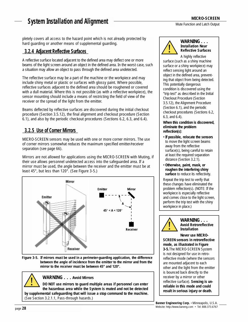
page 28Banner Engineering Corp. • Minneapolis, U.S.A.Website: http://www.baneng.com • Tel: 888.373.6767
System Installation and Alignment MICRO-SCREEN Mute Function and Latch Output
pletely covers all access to the hazard point which is not already protected byhard guarding or another means of supplemental guarding.
3.2.4 Adjacent Reflective SurfacesA reflective surface located adjacent to the defined area may deflect one or morebeams of the light screen around an object in the defined area. In the worst case, sucha situation may allow an object to pass through the defined area undetected.
The reflective surface may be a part of the machine or the workpiece and mayinclude shiny metal or plastic or surfaces with glossy paint. Where possible,reflective surfaces adjacent to the defined area should be roughened or coveredwith a dull material. Where this is not possible (as with a reflective workpiece), thesensor mounting should include a means of restricting the field of view of thereceiver or the spread of the light from the emitter.
Beams deflected by reflective surfaces are discovered during the initial checkoutprocedure (Section 3.5.12), the final alignment and checkout procedure (Section6.1), and also by the periodic checkout procedures (Sections 6.2, 6.3, and 6.4).
3.2.5 Use of Corner MirrorsMICRO-SCREEN sensors may be used with one or more corner mirrors. The useof corner mirrors somewhat reduces the maximum specified emitter/receiverseparation (see page 66).
Mirrors are not allowed for applications using the MICRO-SCREEN with Muting, iftheir use allows personnel undetected access into the safeguarded area. If amirror must be used, the angle between the receiver and the emitter must be atleast 45°, but less than 120°. (See Figure 3-5.)
WARNING . . .Installation NearReflective Surfaces
A highly reflectivesurface (such as a shiny machinesurface or a shiny workpiece) mayreflect sensing light around anobject in the defined area, prevent-ing that object from being detected.This potentially dangerouscondition is discovered using the“trip test” as described in the InitialCheckout Procedure (Section3.5.12), the Alignment Procedure(Section 6.1), and the periodiccheckout procedures (Sections 6.2,6.3, and 6.4).When this condition is discovered,eliminate the problemreflection(s):• If possible, relocate the sensors
to move the light screen beamsaway from the reflectivesurface(s), being careful to retainat least the required separationdistance (Section 3.2.1).
• Otherwise, paint, mask, orroughen the interfering shinysurface to reduce its reflectivity.
Repeat the trip test to verify thatthese changes have eliminated theproblem reflection(s). (NOTE: If theworkpiece is especially reflectiveand comes close to the light screen,perform the trip test with the shinyworkpiece in place.)
!
WARNING . . .Avoid RetroreflectiveInstallation
Never use MICRO-SCREEN sensors in retroreflectivemode, as illustrated in Figure 3-5.The MICRO-SCREEN Systemis not designed for use in retro-reflective mode (where the sensorsare mounted adjacent to eachother and the light from the emitteris bounced back directly to thereceiver by a mirror or otherreflective surface). Sensing is un-reliable in this mode and couldresult in serious injury or death.
!
WARNING . . . Avoid Mirrors
DO NOT use mirrors to guard multiple areas if personnel can enterthe hazardous area while the System is muted and not be detected
by supplemental safeguarding that will issue a stop command to the machine.(See Section 3.2.1.1, Pass-through hazards.)
!
Figure 3-5. If mirrors must be used in a perimeter-guarding application, the differencebetween the angle of incidence from the emitter to the mirror and from themirror to the receiver must be between 45° and 120°.
Emitter Mirror
Receiver
45° < A < 120°
A

page 29Banner Engineering Corp. • Minneapolis, U.S.A.Website: http://www.baneng.com • Tel: 888.373.6767
System Installation and AlignmentMICRO-SCREEN Mute Function and Latch Output
Figure 3-6. Installation of multiple MICRO-SCREEN systems. Alternate emitters andreceivers to avoid optical crosstalk.
b) Two systems stacked.
c) Two systems at right angles.
a) Two systems in a horizontal plane.
Corner mirrors and stands are available from Banner; see page 88.
3.2.6 Installation of Multiple MICRO-SCREEN SystemsWhenever the emitter and receiver pairs of two or more MICRO-SCREEN Systemsare located adjacent to one another, there is potential for optical crosstalk to take
place between systems. To minimize optical crosstalk, alternate the emitters andreceivers, as shown in Figure 3-6.
When three or more systems are installed in a horizontal plane, (as shown for twopairs in Figure 3-6), optical crosstalk may occur between sensor pairs whoseemitter and receiver lenses are oriented in the same direction. In this situation,

page 30Banner Engineering Corp. • Minneapolis, U.S.A.Website: http://www.baneng.com • Tel: 888.373.6767
System Installation and Alignment MICRO-SCREEN Mute Function and Latch Output
optical crosstalk may be controlled by mounting these sensor pairs exactly in linewith each other within one plane, or by adding a mechanical light barrier betweenthe pairs.
3.3 Mounting ProcedureSensor MountingBanner MICRO-SCREEN System emitters and receivers are small, lightweight, andeasy to handle during mounting. The mounting brackets (supplied) allow ±30°rotation.
V-Series emitter/receiver pairs 1422 to 1892 mm (56" to 72") long may be spacedfrom 15 cm to 6 m (6" to 20') apart. All other emitter/receiver pairs may be spacedfrom 15 cm to 9 m (6" to 30') apart. The maximum distance between an emitterand its receiver is reduced if corner mirrors are used (see alignment information,page 66).
From a common point of reference, make measurements to locate the emitter andreceiver in the same plane with their midpoints directly opposite each other. Important: The connector ends of both sensors must point in the same direction(see drawings and WARNING, page 27). Mount the emitter and receiver bracketsusing M6 bolts and Keps nuts (all supplied); see Figure 3-8.
Mount the emitter and receiver in their brackets and position the windows of thetwo units directly facing each other. Measure from one or more reference planes(e.g., the building floor) to the same point(s) on the emitter and receiver to verifytheir mechanical alignment. If the units are positioned exactly vertical or horizontalto the floor, a carpenter’s level is useful for checking alignment. A straightedge or astring extended between the sensors also helps with positioning. Also check “by
Figure 3-7. Emitter and receiver mounting bracket dimensions
Slots have Clearance forM3 Screws (supplied) andAllow for ±30º Rotation
10.7 mm(0.41")12.7 mm
(0.50")
Material: Cold Rolled SteelFinish: Black, Zinc Plated, Chromate Dip
15.7 mm(0.63")23.2 mm
(0.92")
26.7 mm(1.05")
27.2 mm(1.07")
ø15.2 mm(0.60")
2x R 6.4 mm(0.25")
2x ø4.8 mm(0.19")
14.0 mm(0.54")
15.7 mm(0.63") 31.87 mm
(1.25")20.0 mm(0.79")
7.1 mm(0.28")
5.8 mm(0.23")
42.4 mm(1.67")
2.3 mm(0.09")
Min. Radius

page 31Banner Engineering Corp. • Minneapolis, U.S.A.Website: http://www.baneng.com • Tel: 888.373.6767
System Installation and AlignmentMICRO-SCREEN Mute Function and Latch Output
Figure 3-8. Emitter and receiver mounting
NOTE: MICRO-SCREEN sensor brackets aredesigned to mount directly to MSASeries stands (page 88), using thehardware supplied with the stands.
4" to 24" Emitters and Receivers
MICRO-SCREEN Mounting Hardware(supplied with each emitter and receiver)
28" to 72" Emitters and Receivers*
* 28" to 36" sensors include one center bracket and clamps to belocated at the midpoint along the sensor’s length.
40" to 72" sensors include two center brackets and clamps to belocated at 1/3 of the sensor’s length from each end (as shown here).
eye” for line-of-sight alignment. Make any necessary final mechanical adjustments,and hand-tighten the bracket hardware. A detailed alignment procedure is given inSection 6.1.
Center Bracket MountingCenter mounting brackets must be used with longer sensors to provide sensorstability. Sensors 28" to 36" long are supplied with one center bracket, whichshould be positioned at the center of the sensor’s length. Sensors 40" to 72" longare supplied with two center brackets, which should be positioned 1/3 of thesensor’s length from each sensor end. Refer to Figure 3-8 for the following steps.
1) Spread the clamp and snap over the back of the sensor so that the clamp issecurely fastened to the sensor without blocking any beams.
2) Compress the foam spacer and slide the clamp along the length of the sensorhousing to align the clamp with the center mounting bracket as shown inFigure 3-8. Three separate mounting holes are provided on the clamp to allowfor all possible mounting configurations.
3) Connect the clamp to the center bracket using the M3 screw supplied.

page 32Banner Engineering Corp. • Minneapolis, U.S.A.Website: http://www.baneng.com • Tel: 888.373.6767
System Installation and Alignment MICRO-SCREEN Mute Function and Latch Output
Figure 3-9. Emitter and receiver mounting dimensions and location of defined area
Y
27.9 mm(1.10")
17.0 mm(0.67")
L1
L2L3
25.4 mm(1.00")
31.8 mm(1.25")
R13 mm (0.5")Minimum Bend
ø8.1 mm(0.32") max.
StandardModels
Housing LengthL1
Distance Between Bracket HolesL2 L3
V-SeriesModels
Defined AreaY
Emitter USE424 Receiver USR424 137 mm (5.4") 171 mm (6.7") 108 mm (4.2") 102 mm (4")
Emitter USE824Receiver USR824 239 mm (9.4") 273 mm (10.7") 209 mm (8.2") 203 mm (8")
Emitter USE1224Receiver USR1224 340 mm (13.4") 374 mm (14.7") 311 mm (12.2") 305 mm (12")
Emitter USE1624Receiver USR1624 442 mm (17.4") 476 mm (18.7") 412 mm (16.2") 406 mm (16")
Emitter USE2024Receiver USR2024 544 mm (21.4") 578 mm (22.7") 514 mm (20.2") 508 mm (20")
Emitter USE2412Receiver USR2412
Emitter USE2424Receiver USR2424 645 mm (25.4") 679 mm (26.7") 616 mm (24.2") 610 mm (24")
Emitter USE2824Receiver USR2824 747 mm (29.4") 781 mm (30.7") 717 mm (28.2") 711 mm (28")
Emitter USE3212Receiver USR3212
Emitter USE3224Receiver USR3224 848 mm (33.4") 882 mm (34.7") 819 mm (32.2") 813 mm (32")
Emitter USE3624Receiver USR3624 950 mm (37.4") 984 mm (38.7") 920 mm (36.2") 914 mm (36")
Emitter USE4012Receiver USR4012
Emitter USE4024Receiver USR4024 1052 mm (41.4") 1086 mm (42.7") 1022 mm (40.2") 1016 mm (40")
Emitter USE4424Receiver USR4424 1153 mm (45.4") 1187 mm (46.7") 1124 mm (44.2") 1118 mm (44")
Emitter USE4812Receiver USR4812
Emitter USE4824Receiver USR4824 1255 mm (49.4") 1289 mm (50.7") 1225 mm (48.2") 1219 mm (48")
Emitter USE5612Receiver USR5612Emitter USE6412Receiver USR6412Emitter USE7212Receiver USR7212
1458 mm (57.4") 1491 mm (58.7") 1427 mm (56.2") 1422 mm (56")
1661 mm (65.4") 1694 mm (66.7") 1631 mm (64.2") 1626 mm (64")
1864 mm (73.4") 1897 mm (74.7") 1834 mm (72.2") 1829 mm (72")
70 mm (2.75")Minimum
R13 mm (0.5")Minimum Bend

page 33Banner Engineering Corp. • Minneapolis, U.S.A.Website: http://www.baneng.com • Tel: 888.373.6767
System Installation and AlignmentMICRO-SCREEN Mute Function and Latch Output
Routing the CablesConnect the shielded cables to the emitter and receiver (quick-disconnect models).Route them (per local wiring code for low-voltage dc control cables) to the controlbox mounting location. The same cable type is used for both emitter and receiver.The cables should also be trimmed to length; do not trim the cables until you arecertain that you have routed all cables properly. Emitter and receiver cable lengthsmay not exceed 50' (each). Contact factory Applications Department if either orboth cables must be longer than 50'. The cable braid at the control box connectionpoints may be either removed or twisted together with the drain wire (see page37). IMPORTANT: Use ONLY Banner MICRO-SCREEN cables (see page 87).
Mounting the Control Box Mount the MICRO-SCREEN System control box in a convenient location that is freefrom heavy impulse force and high-amplitude vibration. The control box and anyauxiliary Reset switches must be located outside the guarded area, where theswitch operator has a full unobstructed view of the entire guarded area and anyassociated hazards as the Reset is performed. The control box and any auxiliaryReset switches must not be reachable from within the guarded area and must beprotected (through the use of rings or guards, for example) against unauthorized orinadvertent operation. Mounting hole information is given in Figure 3-10 (below).
The MICRO-SCREEN controllers should be configured before initial checkout anduse. Controller configuration is done at the banks of DIP switches along the edgeof each controller module (Figures 3-11 and 3-12). The controller will automaticallysense the length and style of the emitter and receiver, and set its response timeaccordingly.
273.0 mm(10.75")
25.4 mm(1.00")
12 x ø7.5 mm (0.30")
25.4 mm(1.00")
25.4 mm(1.00")
25.4 mm(1.00") 101.4 mm
(4.00")
260.0 mm(10.24")
85.0 mm(3.35")
295.0 mm(11.62")
BANNER ENGINEERING CORPORATION9714 10th Ave. No.• Minneapolis, MN 55441 •612-544-3164
MODEL NO. USCC-1L2M MICRO-SCREEN® Control Box
LIGHTSCREENDIAGNOSTICDISPLAY
LIGHT SCREEN INDICATORS
STEADY: FLASHING:
BLOCKED LOCKOUTCLEAR BLANKINGRESET ALIGNMENT
SYSTEM INDICATORS
SYSTEMDIAGNOSTICDISPLAY
STEADY: FLASHING:
OVERRIDE LOCKOUTOUTPUT ONRESET WAITING FOR RESET
RATED SUPPLY VOLTAGERATED SUPPLY CURRENTFUSE RATINGRESPONSE TIME (See Manual)ENCLOSURE RATINGTEMPERATURE RATINGFSD1, FSD2, SSD RATINGAUX CONTACTS RATINGBLANKING SETUPPERIODIC CHECK PROCEDUREE-STOP RESPONSE TIME
115V ac, 50/60Hz500 mA ac MAX.1.0 A ac, 250V ac48 msUL / CSA TYPE 13, IP640 - 50 C (32 - 122 F)230V ac, 4A Resistive10 VA, 125V ac/dc, 500 mASee Instruction ManualSee Instruction Manual25 ms
230V ac, 50/60Hz250 mA ac MAX.500 mA ac, 250V ac
24V dc2.5 A dc MAX.Internal Resetable
RUN
LIGHTSCREENRESET
SYSTEMRESET
RUN
For use with USE/R... Series Emitters/Receivers and QDU-5..C cables
Electrical shock hazard exists when Control Box door is open. Use extreme caution. Access to the Control Box interior to be byqualified service personnel only (see instruction manual).Always disconnect all power from the MICRO-SCREEN System and from the machine before making wire connections or before replacing any components.
WARNING
Figure 3-10. Control box dimensions and mounting hole locations
WARNING . . .The Control Box mustbe mounted outside
the guarded area at a locationwhich provides an unobstructedview of the entire guarded area,including all danger points. Inaddition, it must NOT be possibleto reach the Key Reset switchfrom inside the guarded area.Failure to do so could result inserious injury or death.
!

3.4 Controller Board ConfigurationBecause the Light Screen Controller and the SystemController each have redundant microprocessors, each boardhas two identical DIP switch banks (Bank A and Bank B);each pair must be set identically. Failure to set Banks A and Bidentically will cause a lockout condition.
Power must always be OFF when changing DIP switchsettings. Changing DIP switch settings with power ON willcause a lockout condition (See Section 5, pages 55-58 forKey Reset routines and troubleshooting).
3.4.1 Light Screen Controller Board ConfigurationThe parameters to be manually configured on the LightScreen controller are:
• Light Screen Controller Auto Power-up,
• One- or Two-Beam Floating Blanking,
• Fixed Blanking (if available).
NOTE: Switch numbers, e.g. “SW1,” refer to both switchbanks A and B.
System Auto Power-up:SW1 ON = Auto Power-up EnabledSW1 OFF = Auto Power-up Disabled *(See Section 2.2)
1-Beam Floating Blanking:SW2 ON = 1-Beam floating blanking enabledSW2 OFF = 1-Beam floating blanking disabled *(See Section 2.1)
2-Beam Floating Blanking:SW3 ON = 2-Beam floating blanking enabledSW3 OFF = 2-Beam floating blanking disabled *(See Section 2.1)
NOTE: Both 1- and 2-Beam Floating Blanking switches set to ON will cause a lockout.
page 34Banner Engineering Corp. • Minneapolis, U.S.A.Website: http://www.baneng.com • Tel: 888.373.6767
System Installation and Alignment MICRO-SCREEN Mute Function and Latch Output
WARNING . . .Blanking Considerations
If blanking is enabled (either fixed orfloating), be aware of the differences in minimumobject sensitivity, depth penetration factor (Dpf),and required light screen separation distance forthe various settings. See Section 3.2.1 for furtherinformation.
!
Light ScreenDiagnostic Display
Bank "A"SW1: Auto Power-UPSW2: 1-Beam Floating BlankingSW3: 2-Beam Floating Blanking
Bank "B"SW1: Auto Power-UPSW2: 1-Beam Floating BlankingSW3: 2-Beam Floating Blanking
ON OFF
OFF
OFFON
Emergency StopSwitch Connections(see section 3.5.10)
Program Mode LEDProgram Set SwitchProgram/Run Slide Switch
Fixed Blanking Models Only
Red
Green
Yellow
Program = OUTRun = IN
Figure 3-11. Light Screen controller board
FloatingBlankingProgram
Standard Series Sensors
2-beam
V-Series Sensors
20.3 mm (0.80")
Maximum Sizeof Undetected
Objects
MinimumObject
Sensitivity
Maximum Sizeof Undetected
Objects
MinimumObject
SensitivityOFF (Not applicable) 19.1 mm (0.75") (Not applicable) 31.8 mm (1.25")
1-beam 7.6 mm (0.30") 31.8 mm (1.25") 20.3 mm (0.80") 57.5 mm (2.25")
44.5 mm (1.75") 45.7 mm (1.80") 82.6 mm (3.25")
Fixed Blanking:Fixed blanking (if used;available on Control BoxUSCC-2L2M only) isprogrammed during the initialcheckout procedure using theProgram switches located onthe light screen controllerboard (see Figure 3-11). SeeSection 3.5.12.1 for completeinformation.
*Factory default setting.

page 35Banner Engineering Corp. • Minneapolis, U.S.A.Website: http://www.baneng.com • Tel: 888.373.6767
System Installation and AlignmentMICRO-SCREEN Mute Function and Latch Output
3.4.2 System Controller Board ConfigurationThe parameters to be manually configured on the System controller are:
• System Auto Power-up,• Monitored Mute Lamp output,• One-Way (directional) or Two-Way (non-directional) Mute Initiate Sequence• One-Channel or Two-Channel EDM, and• Backdoor Time Out.
NOTE: Switch numbers, e.g. “SW1,” refer to both switch banks A and B.
System Auto Power-up:SW1 ON = Auto Power-up EnabledSW1 OFF = Auto Power-up Disabled*(See Section 2.2)
Monitored or Non-Monitored Mute Lamp:SW2 ON = Monitored mute lamp output*SW2 OFF = Mute lamp output not monitored(See Section 2.11.3)
One-Way or Two-Way Mute Initiate:SW3 ON = Two-way mutingSW3 OFF = One-way muting*(See Section 2.11.7)
One-Channel or Two-Channel EDM:SW4 ON = Two-channel EDM enabled*SW4 OFF = One-channel EDM enabled(See Section 2.10)
Backdoor Timer Settings:SW5 OFF = 30 sec. (Mute on Power-Up Disabled)*SW6 OFF
SW5 OFF = 60 sec. (Mute on Power-Up Disabled)SW6 ON
SW5 ON = OFF (Mute on Power-Up Disabled)SW6 OFF
SW5 ON = OFF (Mute on Power-Up Enabled)SW6 ON See Section 2.11.5 for complete information.
*Factory default setting.
SystemDiagnostic Display
ON OFF
OFF
OFFON
Bank "A"SW1: Auto Power-UPSW2: Monitored/Non-Monitored LampSW3: Two/One-Way (Non-Directional/Directional)SW4: Two/One-Channel Monitoring (EDM)SW5: Backdoor TimerSW6: Backdoor Timer
Bank "B"SW1: Auto Power-UPSW2: Monitored/Non-Monitored LampSW3: Two/One-Way (Non-Directional/Directional)SW4: Two/One-Channel Monitoring (EDM)SW5: Backdoor TimerSW6: Backdoor Timer
Red – Override/Lockout
Green – Output ON/OFF
Yellow – Reset/Waiting for Reset
Figure 3-12. System controller board

page 36Banner Engineering Corp. • Minneapolis, U.S.A.Website: http://www.baneng.com • Tel: 888.373.6767
System Installation and Alignment MICRO-SCREEN Mute Function and Latch Output
3.5 Electrical Hookup and CheckoutsMake the electrical connections in the order presented in Sections 3.5.1 through3.5.16. Exercise care when removing control box knockouts, to prevent dam-aging the contents of the control box.
The following wiring connections are located inside the control box:
• Emitter and receiver cables• System power• Output relay connections (FSD1, FSD2, and SSD) • Monitor Relays – Light Screen and System• Light Screen Key Reset switch and test input• Muting device connections• Override connections• Mute lamp• System Key Reset switch• Mute enable input• EDM inputs
Several conduit knockouts are provided around the sides of the control box.When completing the wiring in the following sections, select the knockout locations closest to the internal control box connection points to be accessed(refer to Figures 3-14 and 3-15).
NOTE: Except for emitter and receiver cable entries (for which cable glands aresupplied), it is the user’s responsibility to maintain NEMA 13 sealing atall cable entries into the control box. Wiring barriers inside the controlbox can accept conductors no larger than #14 AWG. The wires used shouldhave an insulation temperature rating of at least 90°C (194°F).
Figure 3-13. MINI-SCREEN with Muting control box knockout locations
WARNING . . .Proper ElectricalHookup
• Electrical hookup must be madeby Qualified Personnel and mustcomply with NEC (NationalElectrical Code) and local stan-dards.
• Make no more connections tothe MICRO-SCREEN System thanare described in Sections 3.5.1through 3.5.14 of this manual.Connection of other wiring orequipment to the MICRO-SCREENSystem could result in seriousbodily injury or death.
!
76.2 mm(3.00")
50.8 mm(2.00")
54.0 mm(2.12")
22.0 mm(0.87")
35.0 mm x 6(1.38")
22.0 mm(0.87")
26.0 mm(1.02")
26.0 mm(1.02")
30.0 mm(1.18")
48.0 mm(1.89")
54 mm(2.13")
NOTE:All knockouts measureø0.875" for 1/2" conduit fittings
BANNER ENGINEERING CORPORATION9714 10th Ave. No.• Minneapolis, MN 55441 •612-544-3164
MODEL NO. USCC-1L2M MICRO-SCREEN® Control Box
LIGHTSCREENDIAGNOSTICDISPLAY
LIGHT SCREEN INDICATORS
STEADY: FLASHING:
BLOCKED LOCKOUTCLEAR BLANKINGRESET ALIGNMENT
SYSTEM INDICATORS
SYSTEMDIAGNOSTICDISPLAY
STEADY: FLASHING:
OVERRIDE LOCKOUTOUTPUT ONRESET WAITING FOR RESET
RATED SUPPLY VOLTAGERATED SUPPLY CURRENTFUSE RATINGRESPONSE TIME (See Manual)ENCLOSURE RATINGTEMPERATURE RATINGFSD1, FSD2, SSD RATINGAUX CONTACTS RATINGBLANKING SETUPPERIODIC CHECK PROCEDUREE-STOP RESPONSE TIME
115V ac, 50/60Hz500 mA ac MAX.1.0 A ac, 250V ac48 msUL / CSA TYPE 13, IP640 - 50 C (32 - 122 F)230V ac, 4A Resistive10 VA, 125V ac/dc, 500 mASee Instruction ManualSee Instruction Manual25 ms
230V ac, 50/60Hz250 mA ac MAX.500 mA ac, 250V ac
24V dc2.5 A dc MAX.Internal Resetable
RUN
LIGHTSCREENRESET
SYSTEMRESET
RUN
For use with USE/R... Series Emitters/Receivers and QDU-5..C cables
Electrical shock hazard exists when Control Box door is open. Use extreme caution. Access to the Control Box interior to be byqualified service personnel only (see instruction manual).Always disconnect all power from the MICRO-SCREEN System and from the machine before making wire connections or before replacing any components.
WARNING

page 37Banner Engineering Corp. • Minneapolis, U.S.A.Website: http://www.baneng.com • Tel: 888.373.6767
System Installation and AlignmentMICRO-SCREEN Mute Function and Latch Output
3.5.1 External Key Reset SwitchesIf it is not possible to mount the control box so that it complies with the warningat left, external Reset switches must be provided for the installation that cancomply with the warning.
When wiring external switches, the corresponding control box-mounted KeyReset switches should be disconnected (or, if this is not possible, the keysremoved and placed under supervisory control). The Light Screen Resetconnection is located at TB1 “Light Screen Reset a/b” (see Figure 3-13). TheSystem Reset connection is located at TB7 “System Reset a/b”. Loose wires fromthe Key Reset switches must be secured (e.g., tape or wire-tie the loose ends) sothey do not cause shorts within the control box.
3.5.2 Emitter and Receiver HookupThe emitter and receiver cables require two control box knockouts. Two cablegland strain relief fittings are supplied with each control box for the entrance ofemitter and receiver cables into the control box. Emitter and receiver cables bothconnect to wiring barrier TB2 (Figure 3-14). Route the cables through theknockouts nearest to barrier TB2. Only the use of Banner cables (see page 87)can ensure reliable communication of data between the controller and the sensors. Match the color-coded terminals of wiring barrier TB2 to colors of thewires in each 5-conductor cable.
Double-check your wiring; incorrect wiring can lead to component damage.There are no user adjustments or connections inside the MICRO-SCREEN emitteror receiver.
WARNING . . . Reset Switch LocationLight Screen andSystem Key Reset
switches are mounted in the controlbox front cover. The control box, orany external System Resetswitch(es), must be accessibleonly from outside, and in full viewof, the hazardous area. Resetswitches must also be out of reachfrom within the safeguardedspace, and must be protectedagainst unauthorized orinadvertent operation (e.g.,through the use of rings or guards).If any areas are not visible from theReset switches, additional means ofsafeguarding must be provided.
!
a
2a2b
1a1b
b
abTESTa
ab
3a 1a3b 1b
4a 2a4b 2b
1a 2a1b 2b
– –+ +
LIGHT SCREEN AUX
MUTING DEVICES
OVERRIDE
a
ab
b
MUTE LAMP
MUTE ENABLEMUTE a SYSTEM RESET b
24V dcCOM
abSYSTEM AUX
b+12V dc
COMT / RT / R
DRAIN
LIGHT SCREEN RESET
LIGHTSCREEN
CONNECTIONS
SSD
TB1
TB3
TB7
TB4
TB5
TB6
TB2
TB9
TB8
Relay Pack
SystemController
BoardMonitoring
LightScreen
ControllerBoard
ab
FSD 2
ab
FSD 1
115V acTB11
230V acTB10
LN
Power Select
Fuse
Figure 3-14. MICRO-SCREEN System electrical connections
Trim braided shieldflush with cable
Trim foil shieldflushwith cable
Uninsulateddrain wire
Emitter and Receiver Cable Preparation
Cable Color CodeColor DescriptionBrown = +12V dcBlue = CommonWhite = T/RBlack = T/RUninsulated = Drain
The “drain wire” is the uninsulatedstranded wire which runs between thebraided shield and the foil shield.Remove the foil shield at the point wherethe wires exit the cable. The braidedshield may be either removed or twistedtogether with the drain wire forconnection to wiring barrier TB2.

page 38Banner Engineering Corp. • Minneapolis, U.S.A.Website: http://www.baneng.com • Tel: 888.373.6767
System Installation and Alignment MICRO-SCREEN Mute Function and Latch Output
3.5.3 Muting Application DesignFollowing are typical applications where muting is used. See Appendix C for moredetailed information.
• Entry/Exit ApplicationsThe muting devices are placed to allow the entry or exit of a pallet or cart ofwork materials to enter or exit a workstation without tripping the Light Screen,and without allowing the entrance of personnel into the hazardous area.
• Home or Station ApplicationsThe muting devices must be placed to mute the safety light screen only when ahazard does not exist or is in another area so that personnel are not exposed toany hazard.
• Robot Load/Unload Station ApplicationThe “Station” muting application uses independent safety light screen circuits,each with its own muting circuit and sensors to protect work locations. When arobot is active in Station A, for example, Station B Light Screen is muted.
• Turret Table ApplicationA “Turret Table” application is similar to the Robot Load/Unload Station mutingapplication, except that any movement of the table ends the mute.
• Power Press ApplicationsThe muting devices are placed so that the mute is initiated only during the non-hazardous, opening portion of the cycle (typically the machine upstroke).
WARNING . . . User is Responsiblefor Safe Applicationof this Product
The muting application examplesdescribed in Appendix C depictgeneralized guarding situations.Every guarding application has aunique set of applicationrequirements. Extreme care isurged to ensure that all legalrequirements are met and that allinstallation instructions arefollowed.
In addition, any questions regardingsafeguarding should be directed tothe factory applications departmentat the telephone number oraddresses listed on the front cover.
!
WARNING . . .Muting is allowedonly during the non-hazardous portion of
the machine cycle (OSHA1910.217©(3)(iii)(d), and ANSIB11.19(1990) section 4.2.3.3.7).
!

page 39Banner Engineering Corp. • Minneapolis, U.S.A.Website: http://www.baneng.com • Tel: 888.373.6767
System Installation and AlignmentMICRO-SCREEN Mute Function and Latch Output
3.5.4 Mute Device Installation and HookupThe user is required by OSHA and ANSI to arrange, install, and operate the safetysystem so as to protect personnel and minimize the possibility of safeguardingdefeat.
Indication that the safety light screen is muted (bypassed) must be provided andbe readily observable (ANSI B11.19 section 4.2.3.3.3). Failure of this indicationshould be detectable and prevent the System from muting. If this is not possible,the operation of the indicator should be verified at suitable intervals.
Mute devices must meet a 3-second simultaneity requirement to activate muting;that is, they must be activated within 3 seconds of one another.
General Muting Device RequirementsThe muting devices (typically sensors or switches) must, at a minimum, complywith the following requirements:
1) There must be a minimum of two independent hardwired muting devices.
2) The muting devices must either both have normally open contacts; or onedevice with a PNP output and one device with a NPN output, both of whichmust fulfill the “input requirements” listed in the specifications (page 85).These contacts must close when the switch is actuated, and must open whenthe switch is not actuated or in a power OFF condition.
3) The activation of the inputs to the muting function must be from separatesources. These sources must be mounted separately in order to prevent anunsafe muting condition resulting from misadjustment, misalignment, or asingle common mode failure. (For example, physical damage to the mountingsurface could cause both muting devices to be knocked out of alignment,resulting in false muting input signals.) Only one of these sources may passthrough, or be affected by, a programmable logic controller or similar device.
4) The muting devices must be installed so that they can not be easily defeatedor bypassed.
5) The muting devices must be mounted so that their physical position andalignment can not be easily changed.
6) It must not be possible for environmental conditions to initiate a mutecondition (e.g., extreme airborne contamination).
7) The muting devices must not be set to use any delay or other timing functions(unless such functions are accomplished so that no single component failureprevents the removal of the hazard, subsequent machine cycles are preventeduntil the failure is corrected, and no hazard is created by extending the mutedperiod).

page 40Banner Engineering Corp. • Minneapolis, U.S.A.Website: http://www.baneng.com • Tel: 888.373.6767
System Installation and Alignment MICRO-SCREEN Mute Function and Latch Output
3.5.5 Mute Device HookupThe control box provides supply voltage, if required, and input connections forthe muting devices (see Figure 3-15). One or two pairs of muting devices(typically sensors or switches) must be used; these pairs are designated M1-M2and M3-M4. The M1 input (1b) and the M3 input (3a) are PNP (sourcing). TheM2 input (2a) and the M4 input (4b) are NPN (sinking). Also available are fourterminals to supply power (+24V dc at 500 mA) to the muting devices, which arelabeled “+” and “-.”
The current draw of all devices, including the mute lamp, must not exceed 500 mA.
Figure 3-16. Two photoelectrics as M1 and M2, using relay output
Figure 3-15. TB4 hookup
WARNING . . . Avoid HazardousInstallations
Two or four independent positionswitches (at M1-M2 or M3-M4)must be properly adjusted orpositioned so that they close onlyafter the hazard no longer exists,and open again when the cycle iscomplete or the hazard is againpresent. If improperly adjusted orpositioned, injury or death couldresult.
The user has the responsibility tosatisfy all local, state, and nationallaws, rules, codes, and regulationsrelating to the use of safetyequipment in any particularapplication. It is extremelyimportant to be sure that allappropriate agency requirementshave been met and that allinstallation and maintenanceinstructions contained in theappropriate manuals are followed.
!
+–
+–
+–
+–
3a3b–+
4a4b
–+
2a2b
1b1a
Figure 3-17. Four limit switches as M1, M2, M3, and M4
3a3b–+
4a4b
–+
2a2b
1b
CarrierBasket
LightScreen
1aM1 M3
M2 M4E
R
3a3b–+
4a4b
–+
2a2b
1b1a M1
M2
TB4
+24V dc
M3
M4

page 41Banner Engineering Corp. • Minneapolis, U.S.A.Website: http://www.baneng.com • Tel: 888.373.6767
System Installation and AlignmentMICRO-SCREEN Mute Function and Latch Output
3.5.6 Mute Lamp Location and HookupTB6 provides connection terminals for one input, Mute Enable (ME a/b), and oneoutput, Mute Lamp (ML a/b) (see Figure 3-19). The Mute Lamp (ML) output is toprovide a visible indication when the safeguarding function of the safety lightscreen is muted. This indication must be readily observable. Failure of thisindication should be detectable and prevent the System from being muted, or theoperation of the indicator should be verified at suitable intervals (see 2.11.3).
The System controller board can be configured for a monitored or non-monitoredmute lamp (see 3.4.2, page 35). If the installation is governed by European (CE)regulations, the mute lamp must be “monitored” (SW2 = ON, banks A and B).This output may also be used as an input to control logic (e.g., a PLC) if “non-monitored” is selected (SW2 = OFF, banks A and B). The current draw of alldevices, including the mute lamp, must not exceed 500 mA.
3.5.7 Mute Enable HookupThe control box provides connection terminals for the Mute Enable input (ME a/b) (see Figure 3-20). Mute Enable gives the user the ability to “frame” orcreate a “window of opportunity” when a mute can occur. The mute enable inputis an isolated contact that must be closed before the System can be muted. Afterthe System is muted, opening of the Mute Enable input has no effect, but it mustbe re-closed before the System can be muted again.
Typical Mute Enable functions include:
1) Contact(s) from machine control logic (e.g., selector switches, relay logic, orPLC/PC logic) to create a window for a mute to begin.
2) Closed or jumpered contact(s) to allow a mute on power up (when selected;see Section 2.11.5).
3) Jumpered input to allow a mute, if mute enable is not used.
4) Open to prevent the initiation of the mute function.
Figure 3-18. Four sensors as M1, M2, M3, and M4 using semiconductor outputs andpower connections
CarrierBasket
R
E
–+
–+
–+
–+
–+
3a3b–+
4a4b
–+
2a2b
1b1a
NPN NPN
PNP PNP
–+
–+
–+
Figure 3-19. Monitored lamp hookup
ab
ba
TB6
24V dc 4W typical (white)
ML
ML
ME
NPN (Sinking) Output+24V dc
ab
Figure 3-20. Mute Enable hookup
ab
ba
TB6
ML ME

page 42Banner Engineering Corp. • Minneapolis, U.S.A.Website: http://www.baneng.com • Tel: 888.373.6767
System Installation and Alignment MICRO-SCREEN Mute Function and Latch Output
3.5.8 External Device Monitoring (EDM) HookupTB8 provides connection terminals for the External Device Monitoring input(1a/1b and 2a/2b), and is located above the SSD, FSD1 and FSD2 outputs.External Device Monitoring (EDM) must be wired in one of three configurations(see Section 3.4.2):
• One-Channel Monitoring, SW4 Bank A&B = OFF• Two-Channel Monitoring, SW4 Bank A&B = ON• No Monitoring, SW4 Bank A&B = ON
Figure 3-21. External Device Monitoring hookups
2aTB8
2b1b1a
MPCE1
MPCE2Jumper
2a2b
1b1a
MPCE1
TB8
MPCE2
2a2b
1b1a
TB8Jumpers
One-Channel Monitoring(SW4 = OFF)
Two-Channel Monitoring(SW4 = ON)
No Monitoring(SW4 = ON)
1a1b
2b2a TB5
Figure 3-22. Override switch hookup
3.5.9 Override Switch HookupThe control box provides connection terminals for the Override switches (seeFigure 3-22). See Section 2.11.6 and the warning at right before connectingswitches.
CAUTION . . . Limit Use ofOverride Function
The Override functionis not for machine setup orproduction; it is to be used onlyto clear the defined area ifmaterial becomes “stuck” in thedefined area. When Override isused, it is the user’sresponsibility to install and useit according to current standards(see Section 2.11.6). In addition,the requirements listed instandards NFPA79 (Section 9.15)and IEC204-1 (Section 9.2.4)must be satisfied.
!
CAUTION . . .JumpersIf the application does
not require this function, theExternal Device Monitoring inputsmust be jumpered and Two-channel EDM must be selected. Itis the user’s responsibility toensure that this does not createa hazardous situation.
!

page 43Banner Engineering Corp. • Minneapolis, U.S.A.Website: http://www.baneng.com • Tel: 888.373.6767
System Installation and AlignmentMICRO-SCREEN Mute Function and Latch Output
3.5.10 Emergency Stop Switch HookupAs shown in Figure 3-23 the E-stop switch must provide one or two contactswhich are closed when the switch is armed. Once activated, the E-stop switchmust open all its contacts, and must be returned to the closed contact positiononly by means of a deliberate action (such as twisting, pulling, or unlocking). Theswitch should be a “positive-opening type,” as described by IEC947-5-1. Amechanical force applied to such a button (or switch) is transmitted directly to thecontacts, forcing them open. This ensures that the switch contacts will openwhenever the switch is activated. NFPA 79 section 13.2, Emergency Stop Devices,specifies the following additional switch (“stop control”) requirements:
• Emergency Stop push buttons shall be located at each operator controlstation and at other operating stations where emergency shutdown shallbe required.
• Stop and Emergency Stop push buttons shall be continuously operablefrom all control and operating stations where located.
• Actuators of Emergency Stop devices shall be colored RED. Thebackground immediately around the device actuator shall be coloredYELLOW. The actuator of a push-button-operated device shall be of thepalm or mushroom-head type.
• The Emergency Stop actuator shall be a self-latching type.
NOTE: Some applications may have additional requirements. The user must referto all relevant regulations.
WARNING . . .Emergency StopSwitch Wiring
• Whenever two or moreEmergency Stop switches areconnected to the same MICRO-SCREEN control box, contacts ofthe corresponding pole of eachswitch must be connectedtogether in series. Never connectthe contacts of multipleEmergency Stop switches inparallel to the MICRO-SCREENcontroller. Parallel connection oftwo or more Emergency Stopswitches to one MICRO-SCREENcontroller defeats the switchcontact monitoring ability of themodule and creates an unsafecondition which could result inserious injury or death.
• Also, when two or moreEmergency Stop switches areused, each switch must beindividually actuated (engaged),then re-armed and the MICRO-SCREEN System controllerreset. This allows the controllerto check each switch and itswiring to detect faults. Failure totest each switch individually inthis manner could result inundetected faults and create anunsafe condition which couldresult in serious injury or death.This check must be performedduring periodic checkouts (seeSection 6).
!
Figure 3-23. Emergency Stop Switch hookup
LightScreen
ControllerBoard
User-SuppliedE-Stop Switch
1234

page 44Banner Engineering Corp. • Minneapolis, U.S.A.Website: http://www.baneng.com • Tel: 888.373.6767
System Installation and Alignment MICRO-SCREEN Mute Function and Latch Output
3.5.11 External Device Monitoring and System Power(Temporary Connection)
For the initial checkout procedure, the External Device Monitoring (EDM, seesection 3.5.8) must be temporarily configured for “No Monitoring” (jumper TB81a-1b, jumper TB8 2a-2b, and turn SW4 switches to ON; refer to Figure 3-21).This will allow the MICRO-SCREEN System to be checked out, by itself, beforepermanent connections are made to the guarded machine.
Ensure the power has been removed from machine or ensure that power is notavailable to the machine controls or actuators, and ensure the machine control(MPCEs) are not connected to the FSD and SSD outputs at this time. Permanentconnections will be made after MICRO-SCREEN initial checkout (see Section3.5.12.).
Connection of System AC power is at the L and the N terminals of control boxwiring barrier TB9. Ensure that the input power has been properly selected atTB10 (230V ac) and TB11 (115V ac). Connection of +24V dc is at TB7 (+24V dcand com). All wiring must comply with NEC and local wiring codes. Do notoperate the MICRO-SCREEN System without a proper earth ground connection ateither of the symbols.
3.5.12 MICRO-SCREEN System Initial CheckoutThe initial checkout procedure will first check the Safety Light Screen portion ofthe System. Once the Light Screen is verified, the Muting function and Overridefunctions will be verified. Follow the checkout procedure for each of the featuresbeing used (Mute and/or Override).
This initial checkout procedure must be performed by a Qualified Person (seeWARNING, Section 3.1). It must be done after configuring the system andconnecting the emitter, receiver, input/output devices, and temporary EDM andpower to the MICRO-SCREEN control box, but before the MICRO-SCREEN isconnected to the machine to be guarded.
The procedure is performed on two occasions:
• To ensure proper installation when the system is first installed, and
• To ensure proper system function whenever any maintenance or modification isperformed on the system or on the machinery being guarded by the System.(See Section 6 for a schedule of required checkouts.)

page 45Banner Engineering Corp. • Minneapolis, U.S.A.Website: http://www.baneng.com • Tel: 888.373.6767
System Installation and AlignmentMICRO-SCREEN Mute Function and Latch Output
3.5.12.1 Safety Light Screen Initial Checkout ProcedureThe Light Screen controller has three operating modes: POWER UP, Key RESET,and RUN. Monitor the six status indicators on the control box (and/or the LightScreen status indicators on the receiver) and refer to Figures 2-4 and 2-5 on pages13 and 14.
1) Enter POWER-UP mode by applying power to the control box. With both AutoPower-ups OFF, the System will power up in a lockout condition (yellow LightScreen indicator only will double-flash). With Auto Power-up ON, the Systemwill automatically enter the RUN mode (step 3). NOTE: Both Key Resets mustbe in the RUN position at power-up.
2) Enter the Light Screen Controller Key RESET mode by turning the left keyclockwise to the RESET position. The yellow Light Screen indicator will glowsteadily.
Hold the switch in RESET position for at least 1/2 second. This allows time forthe microprocessors to run a startup diagnostic check routine.
3) Enter RUN mode by turning the left key counterclockwise from RESET positionto RUN position.
If one or both red status indicator(s) begins to flash when the system is placedin RUN mode, an internal lockout condition exists. Refer to Section 5.1 to deter-mine the cause of the lockout.
If the red and yellow Light Screen status indicators come ON, the defined area isnot clear (one or more light beams are obstructed) or the system is out of align-ment. This is a trip condition. If this occurs, check the defined area forobstruction(s). The red Light Screen indicator will be ON steadily. The yellowLight Screen indicator will be flashing to indicate the relative number of “made”(cleared) light beams; the faster the flash rate, the more beams are made. Thetwo-digit Light Screen Diagnostic Display on the control box will indicate the totalnumber of blocked beams. If all beams are blocked, the red Light Screen indicatorwill be ON steadily, with yellow and green Light Screen indicators both OFF.
If beams are obstructed by one or more objects which will remain fixed inposition, the fixed blanking feature may be used (available on control box USCC-2L2M only). Proceed to step 4 to program fixed blanking. NOTE: Fixed blankingshould only be used when the objects being blanked cannot be moved out ofthe defined area.
If the MICRO-SCREEN System is properly aligned, blanking is properly set, andall obstructing objects are removed from the defined area, the green and yellowLight Screen indicators should come ON after step 3 is performed (the greenLight Screen indicator will flash if blanking is ON, and the yellow Light Screenindicator should be ON steady). If the MICRO-SCREEN System is being set upfor the first time, or if the green and yellow Light Screen indicators do notcome ON during step 3, perform the alignment procedure in Section 6.1.When the emitter and receiver are aligned properly, tighten the emitter andreceiver mounting hardware in position and repeat steps 1-3 above.
Important: Do not perform a System Key Reset at this time. Steps 4, 5 and 6must be completed first, and then the Muting Initial Checkoutprocedure, Section 3.5.12.2, must be followed.
NOTE: Proceed directly to step 5 if fixed blanking is not to be programmed.
Fixed Blanking NotesA) Fixed blanking must be set
within 4 minutes of turning theProgram/Run switch toPROGRAM, or a lockout willoccur, and the procedure mustbe restarted.
B) Floating blanking can beselected to eliminate nuisancelockouts resulting fromunstable clear beams at theedge of fixed objects.
C) Any fixed object in the definedarea must occupy the entirewidth (from emitter toreceiver) of the defined area.Otherwise, hard guarding mustbe added to fill any opening inthe defined area created byfixed blanking (see warning,page 46).
D) The green status indicatorswill flash to indicate use offixed and/or floating blanking.

page 46Banner Engineering Corp. • Minneapolis, U.S.A.Website: http://www.baneng.com • Tel: 888.373.6767
System Installation and Alignment MICRO-SCREEN Mute Function and Latch Output
4) Fixed blanking (control box model USCC-2L2M only). The fixed blankingfeature may be programmed if beams are blocked by one or more fixedobjects. Fixed blanking requires an emitter/receiver pair with 16 or more beams(over 4" long). Fixed blanking is limited to 30% of the total number ofbeams, up to a maximum of 12 beams (see chart below). Contact factoryApplications Department if your application requires fixed blanking of a greaternumber of beams. Programming of fixed blanking involves a simple “teaching”process; it is accomplished using the Diagnostic Display and the Programswitches located on the Light Screen controller board (Figure 3-11).
WARNING . . .Hard Guarding MayAlso Be Required
If any object that is to beignored by fixed blanking doesnot, itself, completely preventaccess to the danger point(s),you must install hard guardingto prevent access past theobject.
Openings in the hard guardingmaterial must meet OSHA criteria(see OSHA 1910.217, Table O-10).
Failure to hard guard anyopening caused by fixedblanking or failure to adequatelyincrease the separation distancewill create an unsafe conditionwhich could lead to seriousinjury or death.
!
WARNING . . .Final SwitchingDevice
The output relays ofthe MICRO-SCREEN System mustbe the final switching devices forthe machinery being guarded.Never wire an intermediatedevice (e.g., a programmablelogic controller - PLC), other thana safety relay, between eitherFSD and the machine primarycontrol elements (Reference ANSIB11.1-1988. Appendix B4). To doso could result in serious bodilyinjury or death.
!
CAUTION . . .Shock Hazard
Electrical shockhazard exists when the MICRO-SCREEN System control box isconnected to the guardedmachine. Use extreme caution toavoid electrical shock at all times.Always disconnect all powerfrom the MICRO-SCREEN Systemand the guarded machine beforemaking any connections orreplacing any component.
*Assumes all blanked beams are adjacent; if multiple areas are blanked (multiple objectsignored) the total blanked area increases slightly.
To prepare for programming of fixed blanking, do the following:
a) Remove all power from the control box (and from the machine to becontrolled, if the System is already wired to the machine).
b) Make sure that Auto Power-up and Floating Blanking programming switches(on the Light Screen controller board, Figure 3-11) are all turned to OFF.
c) Make sure that the Program/Run switch (Figure 3-11) is in the RUNposition (in).
Apply power to the control box (only). The yellow System status indicator willdouble-flash to indicate the System is ready for a Key Reset. DO NOT perform aKey Reset at this time.
Move the Program/Run switch on the Light Screen controller to the Programposition (out). The Program Mode LED will flash and the Diagnostic Display willindicate the total number of beams blocked.
Simulate any mechanical vibration or shock which might be encountered in theapplication and verify that the readout of beams blocked remains stable. Takesteps to eliminate any intermittent beams.
When the number of beams blocked is stable, as indicated by the Light ScreenDiagnostic Display, push the Program Set switch push button on the LightScreen controller (Figure 3-11) for 1/2 to 2 seconds and release. If theprogramming is accepted, the Program Mode LED will stop flashing and go ONsteady. Programming will be rejected if the Program Set switch is helddepressed too long, or not long enough.
If too many beams are blocked, programming is rejected and the DiagnosticDisplay will flash error code 10. If this occurs, check sensor alignment and validblanking criteria (see chart above).
Turn the Program/Run switch to the RUN (in) position. The Program/Run LEDwill go OFF.
DefinedArea
Beams inLight Screen
Maximum FixedBlanked Beams
Total FixedBlanked Area*
Stan
dard
Ser
ies 4" 8 0 N.A.
8" 16 4 2.2"
12" 24 7 3.7"
16" 32 9 4.7"
20" to 48" 40 to 96 12 6.2"
V-Se
ries 24" 24 7 7.7"
32" 32 9 9.7"
40" to 72" 40 to 72 12 12.7"

page 47Banner Engineering Corp. • Minneapolis, U.S.A.Website: http://www.baneng.com • Tel: 888.373.6767
System Installation and AlignmentMICRO-SCREEN Mute Function and Latch Output
Now perform a Light Screen Key Reset. The yellow Light Screen statusindicators will come ON steady, and the green should be flashing to indicatethat blanking is in use.
Remove power from the control box and reconfigure Auto Power-Up andfloating blanking as required for the application. Reapply power and perform aLight Screen Key Reset (if Auto Power-Up is not in use).
5) Perform a System Key Reset (same procedure as a Light Screen Key Reset,performed with the right-hand Key switch); this should result in the green andyellow System status indicators coming ON, and the FSDs closing. At anytime, if one or both red status indicator(s) begins to flash when the Systemgoes into RUN mode, an internal lockout condition exists. Refer to Section 5.1to determine the cause of the lockout.
6) Next, trip test the MICRO-SCREEN Light Screen for object detection capabilityusing the specified test pieces supplied with the control box. To perform thetrip test, both Key Reset switches must be in the RUN (counterclockwise)position, the yellow Light Screen status indicator must be ON steady, and thegreen Light Screen status indicator must either be ON steady (if blanking isOFF) or flashing (if blanking is ON).
NOTE: Verify that the Muting function is not enabled at this time.
Figure 3-24. MICRO-SCREEN Systemtrip test
19.1 mm (0.75") dia. Model STP-2
31.8 mm (1.25") dia.Model STP-4
31.8 mm (1.25" ) dia.Model STP-4
57.5 mm (2.25") dia.Model STP-5
44.5 mm (1.75") dia. Model STP-3
82.6 mm (3.25") dia.Model STP-9
Appropriate Test Pieces for Trip Test
Floating blanking OFF
1-beam floating blanking ON
2-beam floating blanking ON
Standard SeriesEmitters and Receivers
V-SeriesEmitters and ReceiversFloating Blanking Program
Pass the specified test piece, very slowly, down the length of the defined areain three paths: close to the emitter, close to the receiver, and midway betweenthe emitter and receiver (Figure 3-24). In each case, the red Light Screen statusindicator should come ON and remain ON for as long as the test piece remainsin the defined area. When the test piece is removed from the defined area, thegreen Light Screen status indicator must come ON (or flash, if floating blankingis ON). If the green Light Screen status indicator comes ON at any time whenthe test piece is within the defined area, check for reflective surfaces andunguarded areas created by the use of fixed blanking (see WARNINGS, page28). Do not continue until the situation is corrected.
NOTE: The green System status indicator will be OFF after the interruption hasbeen removed. After each pass, reset the System by performing a SystemKey Reset.
If the MICRO-SCREEN System fails any of these checks, do not attempt to usethe System or the guarded machine until the reason for the failure(s) is identi-fied and all failures are corrected.
If the MICRO-SCREEN System passes all of the checks in Section 3.5.12.1, go onto Section 3.5.12.2, Muting Initial Checkout Procedure.
If Muting or Override is not used, then proceed to Section 3.5.13.
How to Clear Fixed Blanking
To clear fixed blanking, removepower from the control box and allobjects from the defined area.Repeat step 4. See page 57 for errorcodes.

page 48Banner Engineering Corp. • Minneapolis, U.S.A.Website: http://www.baneng.com • Tel: 888.373.6767
System Installation and Alignment MICRO-SCREEN Mute Function and Latch Output
3.5.12.2 Muting Initial Checkout ProcedureEnsure that the system passes the initial checkout procedure described in Section3.5.12.1.
1) Continuing from section 3.5.12.1, verify that the MICRO-SCREEN has beenreset and the green and yellow Light Screen and System Status indicators areON. If the yellow System status indicator is double-flashing (indicating theMICRO-SCREEN System is waiting for a System Reset of a latched condition),perform a System Key Reset. At any time, if one or both red statusindicator(s) begins to flash, an internal lockout condition exists. Refer toSection 5.1 to determine the cause of the lockout.
If the Muting function is not used, proceed to Section 3.5.12.3.
During the initial checkout procedure of the Muting feature, if possible, verifythat the power has been removed or is otherwise not available to the machineactuators responsible for hazardous motion. At all times ensure thatpersonnel are not exposed to any hazard.
2) Mute the System by blocking (or activating) both mute devices (typically M1-M2) simultaneously (within 3 seconds).
3) Verify that the Mute indicator comes ON. If not, check the indicator and itswiring, verify that the mute enable input is closed, and check the DiagnosticDisplay for error codes.
4) Interrupt the safety light screen’s defined area with the appropriate test piece;verify the red Light Screen status indicator comes ON, the green indicator isOFF, and the yellow indicator is flashing. Also, verify that the green and yellowSystem status indicators are ON.
NOTE: If the 30- or 60-second Backdoor Timer feature has been selected, theSystem Diagnostic Display will begin to count down; otherwise a flashingdash will appear on the display.
5) Clear the defined area (before the Backdoor Timer expires) and verify that thegreen and yellow Light Screen status indicators come ON. Clear (deactivate)the mute devices before the Backdoor Timer expires and verify the Muteindicator goes OFF. The green and yellow System status indicators shouldremain ON.
6) Verify that it is not possible for a single individual to initiate a mute conditionby triggering the mute devices (for example, by blocking both photoelectricbeams or actuating both switches) and being able to pass through the definedarea without being detected and without issuing a stop command to themachine (where the red System status indicator comes ON, the FSD contactsopen, and a reset of the latch condition is required). Do not expose anyindividual to hazard while attempting to mute the System.
7) Verify that it is not possible for personnel to pass in front of, behind, or nextto the muted object without being detected and without issuing a stopcommand to the machine.
8) If one-way (directional) muting has been selected, verify that the System cannot be muted by blocking (or activating) M3-M4 before M1-M2. Do notexpose any individual to hazard while attempting to mute the System.

page 49Banner Engineering Corp. • Minneapolis, U.S.A.Website: http://www.baneng.com • Tel: 888.373.6767
System Installation and AlignmentMICRO-SCREEN Mute Function and Latch Output
3.5.12.3 Override Checkout ProcedureIf the Override feature is used, the following checkout procedure must becompleted; otherwise proceed to Section 3.5.13.
Ensure that the System passes the initial checkout procedures described inSections 3.5.12.1 and 3.5.12.2.
Continuing from Section 3.5.12.2, with the Light Screen controller in RUN modeand the System has been reset (the green and yellow Light Screen and Systemstatus indicators should be ON, and the FSDs closed; refer to Figures 2-4 and 2-5, pages 13 and 14).
1) Ensure that the positioning of the Override switches allows the operator fullview of the hazardous area and the defined area. Ensure that the location isnot in reach from within the safeguarded space.
2) With Muting de-activated, interrupt the light screen with the appropriate testpiece; verify that the red Light Screen status indicator comes ON, the greenindicator is OFF, and the yellow indicator is flashing. Also, verify that the greenSystem status indicator is OFF and yellow System status indicator is ON.
3) Three seconds after interrupting the defined area, initiate an Override byturning both Override switches to ON (hold in ON position if necessary)simultaneously (within 3 seconds).
4) With the defined area still interrupted, verify that both red status indicatorsare ON, the yellow Light Screen status indicator is flashing at a rateproportional to the number of clear beams, the green System status indicatoris ON, and the FSDs are closed.
5) Continue to interrupt the defined area; after 10 seconds, verify that theOverride drops out. To initiate another Override, return switches to the OFF(open) condition, wait 3 seconds, and then re-close the Override switchessimultaneously (within 3 seconds).
6) Clear the defined area and perform a System Key Reset; the green and yellowSystem status indicators should come ON, and the FSDs should close. If oneor both red System status indicator(s) begin to flash when the System goesinto RUN mode, an internal lockout condition exists. Refer to Section 5.1 todetermine the cause of the lockout.

page 50Banner Engineering Corp. • Minneapolis, U.S.A.Website: http://www.baneng.com • Tel: 888.373.6767
System Installation and Alignment MICRO-SCREEN Mute Function and Latch Output
3.5.13 Output Relay ConnectionsOutput relay connections are made at the FSD1 (Final Switching Device 1), FSD2(Final Switching Device 2), and SSD (Secondary Switching Device) terminals onthe control box (Figure 3-25). These relays are energized (contacts closed) in nor-mal operation when no obstructions are in the defined area. All relays becomede-energized (their contacts open) in a lockout condition. Relays FSD1 and FSD2(only) de-energize in a latch condition. Before continuing, read NOTICE RegardingMPCEs, below right.
The FSD1 output relay connects to Machine Primary Control Element #1 (MPCE 1) on the guarded machine. MPCE 1 is an electrically powered element ofthe guarded machine that directly controls the normal operating motion of themachine; it must be last (in time) to operate when motion is either initiated orarrested. The output contact of relay FSD1 must be connected, as shown in Figure3-25, to control power to Machine Primary Control Element #1. The switching ca-pacity of relay FSD1 is 250V ac max., 4 amps max. (resistive load).
The FSD2 output relay connects to Machine Primary Control Element #2 (MPCE 2) on the guarded machine. MPCE 2 is an electrically powered elementof the guarded machine (in a different control path from MPCE 1) that directlycontrols the normal operating motion of the guarded machine; it must be last (intime) to operate when machine motion is either initiated or arrested. The outputcontact of relay FSD2 must be connected, as shown in Figure 3-25, to controlpower to Machine Primary Control Element #2. The switching capacity of relayFSD2 is 250V ac max., 4 amps max. (resistive load).
Many different types of mechanisms are used to arrest dangerous machine mo-tion. Examples include mechanical braking systems, clutch mechanisms, andcombinations of brakes and clutches. Additionally, control of the arresting schememay be hydraulic or pneumatic.
As a result, MPCEs may be of several control types, including a wide variety ofcontactors and electromechanical valves. If your machine documentation leavesany doubt about the proper connection points for the MICRO-SCREEN Systemoutput relay contacts, do not make any connections. Contact the machine builderfor clarification regarding connections to the MPCEs and MSCE.
The SSD output relay connects to the Machine Secondary Control Element(MSCE) on the guarded machine. The MSCE is an electrically powered element ofthe guarded machine (independent of the MPCEs) that is capable of removingpower from the prime mover of the dangerous part of the machine in the event ofan emergency. The output contacts of the SSD relay must be connected, as shownin Figure 3-25, to the Machine Secondary Control Element such that, if a lockoutcondition occurs, the motive power will be removed from the machine. The switch-ing capacity of the SSD relay is 250V ac max., 4 amps max. (resistive load).
NOTICE Regarding MPCEsEach of the two Machine PrimaryControl Elements (MPCE 1 andMPCE 2) must be capable ofimmediately stopping the dangerousmachine motion, irrespective of thestate of the other. These twochannels of machine control neednot be identical, but the stop timeperformance of the machine (Ts,used to calculate the separationdistance) must take into account theslower of the two channels.
Some machines offer only onePrimary Control Element. For suchmachines, it is necessary to duplicatethe circuit of the single MPCE to adda second Machine Primary ControlElement. Refer to Figure 3-25 orconsult the machine manufacturerfor additional information.
CAUTION . . .Shock Hazard
Electrical shockhazard exists when the MICRO-SCREEN System control moduleis connected to the guardedmachine. Use extreme caution toavoid electrical shock at all times.Always disconnect all power fromthe MICRO-SCREEN System andthe guarded machine before making any connections orreplacing any component.
WARNING . . .Final SwitchingDevice
The output relays ofthe MICRO-SCREEN System mustbe the final switching devices forthe machinery being guarded.Never wire an intermediatedevice (e.g., a programmablelogic controller - PLC), other thana safety relay, between eitherFSD and the machine primarycontrol elements (Reference ANSIB11.1-1988. Appendix B4). To doso could result in serious bodilyinjury or death.
!

page 51Banner Engineering Corp. • Minneapolis, U.S.A.Website: http://www.baneng.com • Tel: 888.373.6767
System Installation and AlignmentMICRO-SCREEN Mute Function and Latch Output
Monitoring
MICRO-SCREEN Control Box
TB8
TB8
TB9
TB7
TB10 TB11
N (V ac)
24V dc
COM
L (V ac)PowerSelect
230V ac 115V ac
EarthGround 115/230 V ac
(Ensure properpower input
has beenselected)
For ac power:
2-Channel External Device Monitoring (EDM)
MICRO-SCREEN Control Box
1-Channel ExternalDevice Monitoring (EDM)
MPCE22a1a
1b2b
MPCE1
MPCE22a
1a
1b2b
a
b
a
b
MPCE1Jumper
SecondarySwitching
Device
SSD
Final SwitchingDevice #2
FSD2
a
bFinal Switching
Device #1
FSD1
EarthGround
dcCommon
For dc power:+24V dc @ 2.5A
MSCE
*
MPCE2
*
*
* Arc Suppression (see warning)
MachineSecondaryControlElement
MachinePrimaryControlElement
MachinePrimaryControlElement
MachineControlCircuit
L (V ac)or
+ (V dc)
N (V ac)or
Common (V dc)
MPCE1
Figure 3-25. MICRO-SCREEN System with Muting generic interface
WARNING . . . Arc Suppressor InstallationIf arc suppressors are used, they MUST be installed as shown across the coils of the machine controlelements. NEVER install suppressors directly across the contacts of the MICRO-SCREEN switchingdevices! It is possible for suppressors to fail as a short circuit. If installed directly across the contacts of a
MICRO-SCREEN switching device, a short-circuited suppressor will create an unsafe condition.
WARNING . . . Output Contacts NecessaryAll MICRO-SCREEN System output contacts (FSD1, FSD2, and SSD) must be used. The generalized wiringconfiguration, shown here, is provided only to illustrate the importance of proper installation. The specificwiring of the MICRO-SCREEN System to any particular machine is solely the responsibility of the installer
and end user.
!
!
Figure 3-25 (below) shows output relay connections in a generic interfacing situation.The connections between the MICRO-SCREEN System outputs and the machine primary and secondary control elements must be direct, and arranged so that anysingle line fault or earth fault will not result in a circuit failure to a potentiallydangerous state.

page 52Banner Engineering Corp. • Minneapolis, U.S.A.Website: http://www.baneng.com • Tel: 888.373.6767
System Installation and Alignment MICRO-SCREEN Mute Function and Latch Output
3.5.14 External Device Monitoring (Permanent Connection)After the initial checkout of Section 3.5.12 has been successfully completed, theEDM bypass circuit, installed in Section 3.5.11, must be removed completely. TheExternal Device Monitoring input then must be properly configured andconnected to the closed monitoring contacts of the MPCEs (see Sections 2.10,3.4.2 and 3.5.8). Refer to the NOTICE Regarding MPCE Monitoring Hookup, atright.
After power is connected to the MICRO-SCREEN System and the output relaycontacts are connected to the machine to be guarded, the operation of theMICRO-SCREEN System with the guarded machine must be verified before thecombined System may be put into service. To do this, a Qualified Person mustperform the Commissioning Checkout Procedure described in Section 6.2.
3.5.15 Monitor Relay OutputsTwo non-safety-related relay outputs are available at TB3: Light Screen AUX andSystem AUX. These monitoring contacts are for light-duty, non-safety relatedcontrol functions, such as an input to a programmable logic controller (PLC).See Figures 2-4 and 2-5 in Section 2.4 for detailed output status in relationshipto the LED status indicators and the safety outputs (FSD1, FSD2, and SSD).
3.5.16 Accessory ConnectionsLight Screen Remote TestLight Screen Remote Test input connects to Test a and Test b at TB1 (see Figure 3-14, page 37). When connected together (shorted) for a minimum of 50milliseconds, a blocked beam condition is simulated for as long as theconnection is made.
Light Screen ResetLight Screen Reset input connects to Reset a and Reset b at TB1 (see Figure 3-14, page 37). It is functionally equivalent to the Light Screen Key Reset switch(on the left side of the control box front cover).
System ResetSystem Reset input connects to TB7 terminals a and b (see Figure 3-14, page37). It is functionally equivalent to the System Key Reset switch (on the right sideof the control box front cover).
If an external switch is connected to either reset input, then:
• The corresponding control box Key Reset switch should be disconnected, or
• The corresponding control box Key Reset switch key should be removed andplaced under supervision.
NOTICE RegardingMPCE Monitoring
HookupIt is strongly recommendedthat one normally closedmonitoring contact of eachMPCE be wired (as shown inFigure 3-25, page 51) as MPCEmonitor. If this is done, properoperation of the MPCEs will beverified.
MPCE monitoring contactsmust be used in order tomaintain control reliability.

page 53Banner Engineering Corp. • Minneapolis, U.S.A.Website: http://www.baneng.com • Tel: 888.373.6767
System Installation and AlignmentMICRO-SCREEN Mute Function and Latch Output
In any case, the control box and any external resets must be located so thatSystem reset is possible only from outside, and in full view of, the hazardousarea. The switches must also be out of reach from within the safeguarded space.If any hazardous areas are out of view from the switch location(s), additionalmeans of safeguarding must be provided.
Using a Key switch provides some level of personal control, because the key maybe removed. This will hinder a reset while the key is under the control of anindividual, but must not be relied upon solely to guard against accidental orunauthorized reset.

page 54Banner Engineering Corp. • Minneapolis, U.S.A.Website: http://www.baneng.com • Tel: 888.373.6767
Operating Instructions MICRO-SCREEN Mute Function and Latch Output
4. Operating Instructions
4.1 Security ProtocolThe MICRO-SCREEN control box has a lockable cover and two key-operatedfront-panel Reset switches.
In order to prevent access by unauthorized personnel, and to ensure that alllockout conditions come to the attention of a person qualified to deal with them,a lock must be inserted in the lockable cover and the key (or combination) to thislock must be kept in the possession of a Qualified Person as defined inANSI/ASME B30.2-1983 (see Glossary). Qualified Persons only should haveaccess to the interior of the MICRO-SCREEN System control box.
The key to the front-panel Reset switches should be available only to a Designated Person or Persons. A Designated Person is one who is identified and designated in writing, by the employer, as being appropriately trained andqualified to perform a specified checkout procedure. A machine operator whomeets these requirements may be a Designated Person.
4.2 Periodic Checkout RequirementsIn addition to the checkouts that are performed by a Qualified Person or persons atthe time that the MICRO-SCREEN System is installed and put into service, thefunctioning of the MICRO-SCREEN System and the machine it guards must beverified on a regular periodic basis to ensure proper operation. This is abso-lutely vital and necessary. Failure to ensure proper operation can lead toserious injury or death.
See Section 6 for checkout schedules and procedures.
WARNING . . .Verify ProperOperation
The Banner MICRO-SCREEN System can do the jobfor which it was designed only ifit and the machine it guards areoperating properly, bothseparately and together. It is theuser’s responsibility to verify properoperation, on a regular basis,as instructed in Section 4.2 andSection 6.
If the MICRO-SCREEN Systemand the guarded machine do notperform exactly as outlined inthe checkout procedures, thecause of the problem must befound and corrected before thesystem is put back into service.Failure to correct such problemscan result in serious bodilyinjury or death.
!

page 55Banner Engineering Corp. • Minneapolis, U.S.A.Website: http://www.baneng.com • Tel: 888.373.6767
Troubleshooting and MaintenanceMICRO-SCREEN Mute Function and Latch Output
5. Troubleshooting and Maintenance
5.1 Troubleshooting Lockout ConditionsA lockout condition causes the output relays FSD1, FSD2, SSD, and System AUXto open, shutting down the MPCEs and MSCE of the guarded machine. A lockoutcondition resulting from an internal fault is indicated by the red statusindicator(s) flashing.
A power-up/power interrupt lockout is indicated by the yellow status indicator(s)double-flashing, and is normal if one or both Auto Power-Up features are turnedOFF (factory default). This type of lockout requires only the proper Key Resetroutine for operation to continue.
A lockout condition will occur:
Power-up/Power Interrupt Lockouts• Routinely upon power-up of the MICRO-SCREEN System (unless Auto
Power-up is ON; see Figures 2-4 and 2-5, pages 13 and 14); or• If power to the MICRO-SCREEN System is interrupted (unless Auto
Power-up is ON; see Figures 2-4 and 2-5).Internal Lockout Conditions
• If either Key switch is in the RESET position at power-up (with AutoPower-up ON); or if either Key switch is switched to RESET while theSystem is in RUN mode;
• If the Program/Run switch (Figure 3-11) is in the PROGRAM position atpower-up;
• If Floating Blanking switches are in the ON position when theProgram/Run switch is switched to the PROGRAM position;
• If both 1-beam and 2-beam Floating Blanking switches are in the ONposition;
• If fixed blanking is not set within approximately 4 minutes of moving theProgram/Run switch to the PROGRAM position;
• If Fixed Blanking has been programmed, and any fixed object is removedfrom or moved within the defined area;
• If an FSD (Final Switching Device – see Glossary) relay does not “dropout” within its specified time;
• If the SSD (Secondary Switching Device – see Glossary) relay has de-energized;
• If corresponding control box switch settings are inconsistent with eachother or if they are changed while the System is in RUN mode;
• If the self-checking circuits of either microprocessor detect a componentfailure within the MICRO-SCREEN System itself; or
• If either (or both) Emergency Stop switch contacts open.
WARNING . . .Power Failures
Power failures orother MICRO-SCREENSystem lockout
conditions should always beinvestigated immediately by aQualified Person. With the exception of power-up/powerinterrupt lockouts, a lockout is adefinite indication of a problemand should be investigated atonce. Attempts to continue tooperate machinery by bypassing the MICRO-SCREENSystem are dangerous and couldresult in serious bodily injury ordeath.
!
CAUTION . . .High Voltage
Dangerous voltagesare present inside the
MICRO-SCREEN System controlbox whenever ac power to themachine control elements is ON.Exercise extreme caution when-ever ac voltage is or may bepresent!

page 56Banner Engineering Corp. • Minneapolis, U.S.A.Website: http://www.baneng.com • Tel: 888.373.6767
Troubleshooting and Maintenance MICRO-SCREEN Mute Function and Latch Output
Key Reset Routine
Important: The Light Screen controller must be reset before a System Key Resetcan be performed. See figures 2-4 and 2-5 (pages 13 and 14) forproper indicator and output status conditions.
If both the red Light Screen and System status indicators are flashing:
A) Attempt to reset the Light Screen controller first by turning the Light Screenkey from RUN to RESET for approximately 1/2 second (wait for solid yellow),and then returning the key to the RUN position. If the green and yellow LightScreen status indicators come ON (or begin to flash) proceed directly to step“D.”
B) If the red Light Screen status indicator stops flashing and comes ON solid(with the yellow Light Screen status indicator single-flashing or OFF), the faulthas been cleared, but the light screen is either out of alignment or one ormore beams are blocked. Realign or remove the obstruction (see Section2.11.6, Override); the green and yellow Light Screen status indicators shouldcome ON (green will flash if blanking is ON). If this is accomplished, go tostep “D.”
C) If the Light Screen controller is still in a lockout condition, note the error codeon the Light Screen Diagnostic Display. See page 57 for a list of Light Screenerror codes and possible causes and/or corrective measures of the faultcondition.
If only the System red status indicator is flashing and the green and yellowLight Screen status indicators are ON (green will flash if blanking is ON):
D) Attempt to reset the System controller by turning the System Reset Key fromRUN to RESET for approximately 1/2 second (wait for solid yellow), and thenreturn the key to the RUN position. If the green and yellow System statusindicators come ON, the System has been reset and the outputs should beclosed.
E) If the System controller is still in a lockout condition, note the error code onthe Muting Diagnostic Display. See page 58 for a list of System error codesand possible causes of the fault condition.
If the lockout condition was due to a momentary power interruption that hasbeen corrected, the MICRO-SCREEN will now operate normally. Upon recoveryfrom a power interruption, checkout procedure 6.3 on page 72 must beperformed.

page 57Banner Engineering Corp. • Minneapolis, U.S.A.Website: http://www.baneng.com • Tel: 888.373.6767
MICRO-SCREEN Mute Function and Latch Output Troubleshooting and Maintenance
5.2 Diagnostic DisplaysA lockout condition resulting from an internal Systemfault is indicated by the red status indicators flashing,and an error code number appearing in either or both ofthe Diagnostic Displays. In this case, the QualifiedPerson must note the error code and interpret the causeof the lockout from the tables in Figures 5-1 and 5-2.These diagnostic tables are also found inside the controlbox on the side of the control boards.
The MICRO-SCREEN System will not operate if its self-checking circuits detect an internal problem. Neither KeyReset will have any effect until the problem is corrected.Take the corrective measure(s) corresponding to theerror code, then perform the appropriate Key Resetsequence. If further assistance is required, contact yourBanner field service engineer or the factory ApplicationsEngineering Department.
If no status indicators are ON, power to the System mayhave been lost. The green LED on the power supplyboard indicates the presence (LED ON) or absence (LEDOFF) of dc power at the power supply board. It ispossible for power to be present at the input of thepower supply even if the dc Power LED is OFF.
Very carefully check for voltage across terminals L andN (or + and -) of wiring barrier TB9 (for ac powerinput), or across 24V dc and COM terminals of TB7 (fordc power input). If voltage is not present, power to theMICRO-SCREEN System has been lost, and the cause isoutside the system.
Check for 12V dc at connector block TB2. If 12V dc isnot present there, turn off the power to the control boxand check the fuse. If the fuse is bad, replace it (Section5.3.1). If the fuse is good, and 12V dc is still not presentat TB2, a power supply failure has occurred.
0
Error No. Error Type/Action
- System is OK
1Relay Signal Error• Replace Relay/Power Supply• Replace Light Screen
Controller
2Key Input Error• Check Key Position• Invalid Key Reset• Replace Key Switch
3Controller Error• Replace Light Screen
Controller
4Receiver Error• Check Receiver Cable• Replace Receiver
5Emitter Error• Check Emitter Cable• Replace Emitter
6Communication Error• Check Cable Connections• Observe Noise Indicator• Replace Emitter/Receiver
7DIP Switch Error• Check Switch Settings• Replace Light Screen
Controller
8CPU Error• Replace Light Screen
Controller
9E-Stop Input Error• Check E-Stop Circuit• Replace Light Screen
Controller• Replace Relay/Power Supply
10 System Error• Check Fixed Beams
11 Power Up Error• Check Prog/Run Switch
E-Stop Open• Check E-Stop Circuit• Replace Light Screen
Controller• Replace Relay/Power Supply
12Programming Error• Too Much Time• Floating Blanking ON
NOTE: Flashing decimal point indicatesnoisy environment
Figure 5-1. Light Screen Controller Board Diagnostic Display andinterpretation of error codes

page 58Banner Engineering Corp. • Minneapolis, U.S.A.Website: http://www.baneng.com • Tel: 888.373.6767
MICRO-SCREEN Mute Function and Latch OutputTroubleshooting and Maintenance
Error No. Error Type/Action
- System is OK
31Relay Signal Error• Replace Relay/Power Supply• Replace System Controller
32System Reset Key Input Error• Check System Reset Key Position• Invalid System Key Reset• Replace System Key Switch
33 Muting Controller Error• Replace System Controller
34Light Curtain Error• Check Light Screen Diagnostics• Replace Light Screen Controller
35Override Input Error• Check Override Input Wiring• Replace Override Input Switch
36Muting Lamp Error• Check Muting Lamp Connection• Replace Light Bulb
37DIP Switch Error• Check Switch Settings• Replace System Controller
38MPCE 1 Error• Check MPCE 1 Monitors Wiring• Check DIP Switch Settings• Replace System Controller
39MPCE 2 Error• Check MPCE 2 Monitors Wiring• Check DIP Switch Settings• Replace System Controller
40Two-Channel Monitor Error• Check Wiring of MPCE 1
and MPCE 2• Replace Muting System Controller
50 Back Door Timing Expired• See Manual (Section 3.4.2)
51 Muting Simultaneity Error• See Manual (Section 3.5.4)
Figure 5-2. System Controller Board Diagnostic Display and interpretation oferror codes

page 59Banner Engineering Corp. • Minneapolis, U.S.A.Website: http://www.baneng.com • Tel: 888.373.6767
Troubleshooting and MaintenanceMICRO-SCREEN Mute Function and Latch Output
5.3 Effects of Electrical and Optical NoiseThe MICRO-SCREEN System is designed and manufactured to be highly resistantto electrical and optical noise and to operate reliably in industrial settings.However, serious electrical and/or optical noise may cause a random latchcondition. In very extreme cases, a lockout is possible. In order to minimize theeffects of transitory noise, the MICRO-SCREEN System will respond to noise onlyif the noise is detected on multiple consecutive scans. The decimal point of theDiagnostic Display will flash to indicate the presence of electrical or optical noise.This indicator can be used to track down particularly offensive noise sources (seesidebar at left). Simply observe the decimal point indicator while shutting down orisolating the suspected sources.
5.4 Servicing and Maintenance
5.4.1 Fuse Testing and ReplacementTurn OFF power to the control box and the machine being guarded beforeproceeding.
The MICRO-SCREEN System control box fuse is located in a fuseholder on thepower supply board (see Figure 3-14, page 37). Remove the fuse from the holder.Visually inspect the fuse and/or test its conductivity using an ohm meter or acontinuity tester. The fuse is a 3AG or 5x20 mm slow-blow type (see specifica-tions, page 84).
5.4.2 Control Boards and Relay/Power Supply ReplacementMICRO-SCREEN Systems are designed for reliability. While replacement of thecontroller or relay/power supply boards is not normally required, thesecomponents have been designed to be easily replaceable as a convenience to thecustomer. See the instructions included with the replacement board. To maintaincontrol reliability, use only Banner-supplied replacement relays with forced-guided contacts. See Replacement Parts, page 89.
NOTE: Do not open the emitter or receiver housing. The emitter and receivercontain no field-replaceable components. If repair is necessary, returnthe unit to the factory. Do not attempt to repair an emitter or receiveryourself.
Electrical and Optical Noise
Check the following if the reddecimal point of the Light ScreenDiagnostic Display is flashing:
• Poor connection betweencontrol box and earth ground
• Drain wire of emitter and/orreceiver not connected to TB2(see Figure 3-14)
• Sensor wires or output wiresrouted too close to “noisy”wiring
• Optical interference fromadjacent light screens or otherphotoelectrics
WARNING . . .Shut Down MachineryBefore ServicingThe machinery con-
nected to the MICRO-SCREENSystem must not be operating atany time during this procedure.You may be working close to ahazardous area of your machinerywhile servicing the MICRO-SCREENSystem. Servicing the MICRO-SCREEN System while thehazardous machinery isoperational could result in seriousbodily injury or death.
!
WARNING . . .Use Only GenuineBanner ReplacementParts
If replacement parts are ever required, always use only genuineBanner-supplied replacement parts(see page 61). Do not attempt tosubstitute parts from another manufacturer. To do so couldimpair the operation of the MICRO-SCREEN System and could resultin serious bodily injury or death.
!
CAUTION . . .AC Voltage Danger
Dangerous voltages arepresent inside the
MICRO-SCREEN System controlbox whenever ac power to themachine control elements is ON.Exercise extreme caution whenever ac voltage is or may bepresent! Always disconnect allpower from the MICRO-SCREENSystem and the guarded machinebefore making any wire connectionsor before replacing any component.
The control box should be openedand/or serviced only by a QualifiedPerson (see Section 4.1).

page 60Banner Engineering Corp. • Minneapolis, U.S.A.Website: http://www.baneng.com • Tel: 888.373.6767
MICRO-SCREEN Mute Function and Latch OutputTroubleshooting and Maintenance
5.4.3 CleaningThe MICRO-SCREEN System control box is constructed of welded steel with ablack polyester paint finish, and is rated NEMA 13 (IP64). It may be cleaned usingmild detergent or window cleaner and a soft cloth.
MICRO-SCREEN emitters and receivers are constructed of aluminum with ayellow painted finish and are rated NEMA 4, 13 (IP65). Lens covers are acrylic.Emitters and receivers are best cleaned using mild detergent or window cleanerand a soft cloth. Avoid cleaners containing alcohol, as they may damage theacrylic lens covers.
5.4.4 Warranty ServiceIf it ever becomes necessary to return a MICRO-SCREEN component to thefactory, please do the following:
1) Contact the Banner Factory Application Engineering group at the address ornumbers listed below.
Banner Engineering Corp.9714 - 10th Avenue No.Minneapolis, MN 55441
Phone: 888.373.6767email: [email protected]
They will attempt to troubleshoot the system from your description of theproblem. If they conclude that a component is defective, they will issue an RMA(Return Merchandise Authorization) number for your paperwork, and give youthe proper shipping address.
2) Pack the component(s) carefully. Damage which occurs during return shippingis not covered by warranty.

page 61Banner Engineering Corp. • Minneapolis, U.S.A.Website: http://www.baneng.com • Tel: 888.373.6767
MICRO-SCREEN Mute Function and Latch Output Alignment and Checkout
6. Alignment and CheckoutStudy each procedure from beginning to end to make sure that you understandeach step before you start. Refer all questions to the Banner ApplicationsEngineering Department: Banner Engineering Corp.
9714 - 10th Avenue No. Minneapolis, MN 55441Phone: 888.373.6767email: [email protected]
Section 6.1 is a procedure for optically aligning a MICRO-SCREEN System. Sections6.2, 6.3, and 6.4 are periodic performance checkout procedures for the MICRO-SCREEN System.
Checkouts must be performed according to checkout procedure 6.3, page 72,as follows:
1) By a Designated Person at every power-up of the MICRO-SCREEN System;
2) By a Qualified Person following the correction of every lockout condition;
3) By a Designated Person at every shift change or machine setup change;
Checkouts must be performed according to checkout procedure 6.4, page 76, as follows:
1) By a Qualified Person semi-annually (every 6 months) following installationof the MICRO-SCREEN System..
See Figures 6-1 and 6-2 on pages 62 and 63 for operating status conditions.
V-Series emitter/receiver pairs 1422 to 1892 mm (56" to 72") long may be spacedfrom 15 cm to 6 m (6" to 20') apart. All other emitter/receiver pairs may be spacedfrom 15 cm to 9 m (6" to 30') apart. The maximum distance between the sensors isreduced if corner mirrors are used (see alignment information on page 66).
6.1 MICRO-SCREEN System AlignmentThis alignment procedure begins with the assumption that the MICRO-SCREENSystem has been mechanically aligned as described in Section 3.3.
Follow the measures outlined below to maximize MICRO-SCREEN System excessgain. If reflective surfaces are near the defined area, read alignment step #5 (pages64-65) before proceeding further, to prevent possible reflection problems.
Only a Qualified Person may align the MICRO-SCREEN System, as follows:
1) Turn OFF power to the MICRO-SCREEN System and to the guarded machine.Leave power to the guarded machine OFF, and power-up the MICRO-SCREENSystem only with both keys in the RUN position.
2) The MICRO-SCREEN will power up into a power-up lockout condition (unlessAuto Power-up is ON; then proceed to step #3). Remove all obstructions fromthe defined area and perform a Light Screen Key Reset:
a) Turn the Light Screen Key clockwise to the RESET position, wait at least1/2 second, then
b) Turn the Light Screen Key counter-clockwise to the RUN position.
WARNING . . .Shut Down MachineryBefore ProceedingThe machinery
connected to the MICRO-SCREENSystem must not be operating atany time during the alignmentprocedure of Section 6.1. You maybe working close to hazardous areasof your machinery while aligning theMICRO-SCREEN System. Doing sowhile the hazardous machinery is operational could result in seriousbodily injury.
!

page 62Banner Engineering Corp. • Minneapolis, U.S.A.Website: http://www.baneng.com • Tel: 888.373.6767
Alignment and Checkout MICRO-SCREEN Mute Function and Latch Output
Applying Power toControl Box Results in aPower-up Lockout State
Turn L.S. Key toLIGHT SCREEN RESET
Position for 0.5 seconds
Turn L.S. Key to RUN
Turn SYS Key to RUN
Power-up
Light Screenontroller Reset
OperationSequence
RequiredOperation
OutputStatus
Indicator StatusLight Screen System
Is the Defined Areaclear and system latched (see right)
Turn SYS Key toSYSTEM RESET
Position for 0.5 Seconds
System Power-upComplete (see right)
See Next Pagefor Other Indicationsand Possible Causes.
If Light Screen Auto Power-up is ON when power is applied to the MICRO-SCREEN, the Light Screen Controller will perform an automatic Light Screen Reset afterpassing an internal system checkout. This places the Light Screen controller into RUNmode and allows the System Controller to be reset.
If both Light Screen and System Auto Power-up are ON when power is applied to theMICRO-SCREEN, both controllers will perform automatic resets after passing internalcheckouts. At this time, the System Controller will energize the outputs to an ON statewithout a Key Reset.
NO
NO
Yes
Yellow
Green
Red
Yellow
Green
Red
FSD1 FSD2 SSDL.S.AUX
SYSAUX
FSD1 FSD2 SSDL.S.AUX
SYSAUX
Yellow
Green*
RedFSD1 FSD2 SSD
L.S.AUX
SYSAUX
Yellow
Green*
RedFSD1 FSD2 SSD
L.S.AUX
SYSAUX
Yellow
Green
RedFSD1
LED OFF
LED ON
LED Single-Flashing
LED Double-Flashing
FSD2 SSDL.S.AUX
SYSAUX
NOTE: Both keys must be in the RUN position at power-up. The following flowchart assumes both Light Screen Auto Power-up and System Auto Power-up are OFF (see NOTES below if either Auto Power-up is ON).
L.S. = Light ScreenSYS = System
NOTE:* The green Light Screen status indicator will flash if blanking is ON.
Figure 6-1. Operating status conditions

page 63Banner Engineering Corp. • Minneapolis, U.S.A.Website: http://www.baneng.com • Tel: 888.373.6767
Alignment and CheckoutMICRO-SCREEN Mute Function and Latch Output
OutputStatus
PossibleCauses
Indicator StatusLight Screen System
Yellow**
Green
Red FSD1 FSD2 SSDL.S.AUX
SYSAUX
LED OFF
LED ON
LED Single-Flashing
LED Double-Flashing
Defined Area Blockedand is Waiting forSystem Reset(Power-up Lockout)
Yellow**
Green
Red FSD1 FSD2 SSDL.S.AUX
SYSAUX Defined Area Blocked
and System is Latched(after System Reset)
Yellow
Green
Red FSD1 FSD2 SSDL.S.AUX
SYSAUX Defined Area Clear and
System is Latchedand Waiting for Reset
Yellow**
Green
Red FSD1 FSD2 SSDL.S.AUX
SYSAUX Override Enabled
(Defined Area isBlocked and Systemis Latched)
Yellow
Green
Red FSD1 FSD2 SSDL.S.AUX
SYSAUX Lockout of Light
Screen Controller
Yellow
Green
Red FSD1 FSD2 SSDL.S.AUX
SYSAUX Lockout of System
Controller only, Defined Area Clear
Yellow**
Green
Red FSD1 FSD2 SSDL.S.AUX
SYSAUX Lockout of System
Controller only, Defined Area is Blockedand System is Latched
NOTE:** The yellow Light Screen status indicator will be OFF if the Emitter and Receiver are not aligned; otherwise it will flash at a rate proportional to the number of "made" beams.
Figure 6-2. Operating status conditions

page 64Banner Engineering Corp. • Minneapolis, U.S.A.Website: http://www.baneng.com • Tel: 888.373.6767
Alignment and Checkout MICRO-SCREEN Mute Function and Latch Output
3) Upon completion of the Light Screen Key Reset (step #2), the Light Screenstatus indicators will indicate either a blocked or a clear condition.
a) A blocked condition is indicated by the red indicator ON steady and theyellow indicator flashing at a rate proportional to the number of aligned,unblocked beams. The Light Screen Digital Display on the control box willindicate the total number of blocked beams. If all the beams are blocked,the yellow Light Screen status indicator will be OFF. Go to step #4.
b) A clear condition is indicated by the red indicator OFF and the green andyellow indicators ON steadily (green will flash if blanking is ON). Furtheralignment is not necessary.
c) A lockout condition is indicated by a flashing red Light Screen or Systemindicator. See Section 5 for troubleshooting.
4) A blocked condition after reset indicates that one or more of the beams ismisaligned or interrupted. When this occurs:
a) Check carefully for any obstructions in the path of the beams within thedefined area (the limits of which are indicated by the ends of the emitterand receiver windows; see Figure 3-9).
b) If the defined area is completely clear of obstructions, loosen the fourslotted hex M3 screws which fasten the receiver to its mounting brackets.Verify that sensors are level, then slowly rotate the receiver first to theright and then to the left while watching the status indicators on thereceiver base.
c) If the green indicator does not come ON, regardless of the receiver’sangle, loosen the emitter and rotate both sensors relative to each otheruntil the green indicator comes ON. Secure the emitter and receiver in thecenter of the area of rotation where the yellow and green indicators areON steady (green will flash if blanking is ON).
d) If the green indicator still fails to come ON, then re-check the sensormounting (see Section 3.3), and re-align if necessary.
5) “Trip test” the MICRO-SCREEN System for object detection capability usingthe test piece(s) supplied with the control box. To perform this test, both KeyReset switches must be in the RUN position, the yellow Light Screen statusindicator must be ON steady, and the green Light Screen status indicator mustbe either ON steady (if blanking is OFF) or flashing (if blanking is ON). Resetthe System (using the Key Reset procedure), if necessary, to attain this condition (see step #2).
19.1 mm (0.75") dia. Model STP-2
31.8 mm (1.25") dia.Model STP-4
31.8 mm (1.25" ) dia. Model STP-4
57.5 mm (2.25") dia.Model STP-5
44.5 mm (1.75") dia. Model STP-3
82.6 mm (3.25") dia.Model STP-9
Appropriate Test Pieces for Trip Test
Floating blanking OFF
1-beam floating blanking ON
2-beam floating blanking ON
Standard SeriesEmitters and Receivers
V-SeriesEmitters and ReceiversFloating Blanking Program

page 65Banner Engineering Corp. • Minneapolis, U.S.A.Website: http://www.baneng.com • Tel: 888.373.6767
Alignment and CheckoutMICRO-SCREEN Mute Function and Latch Output
Perform the trip test as follows:Pass the appropriate specified test piece downward through the defined area atthree points (see Figure 6-3):
a) Close to the receiver,
b) Close to the emitter, and
c) Midway between the emitter and receiver.
In each case, the red Light Screen status indicator must come ON and remain ONfor as long as the test piece is within the defined area.
The green Light Screen status indicator should come ON only when the test pieceis withdrawn from the defined area. If the green status indicator comes ON at anytime when the test piece is within the defined area, check for reflective surfaces orunguarded areas created by use of fixed blanking (see Warnings, page 76). Do notcontinue until the situation is corrected.
WARNING . . .If Trip Test Indicates aProblem
If the MICRO-SCREENSystem does not respond properlyto the trip test, do not attempt touse the System. If this occurs, theSystem cannot be relied upon tostop dangerous machine motionwhen a person or object enters thedefined area. Serious bodily injuryor death could result.
!
Figure 6-3. MICRO-SCREEN trip test

page 66Banner Engineering Corp. • Minneapolis, U.S.A.Website: http://www.baneng.com • Tel: 888.373.6767
Alignment and Checkout MICRO-SCREEN Mute Function and Latch Output
Use of Corner MirrorsMICRO-SCREEN sensors may be used with one or more MSM Series cornermirrors for guarding along more than one side of an area.
The Accessories section lists the 12 available lengths of corner mirrors forsensors up to 48" long (see page 88). These rear-surface glass mirrors are ratedat 85% efficiency; sensing range (and therefore excess gain) is reduced whenusing mirrors. The following table lists the resultant range when from one to fourMSM Series corner mirrors are used in either sensing path.
Maximum Emitter and Receiver Separation
Number of Corner Mirrors 1 2 3 4Sensor lengths from102 mm to 1219 mm (4" to 48")
8.5 m(28')
7.8 m(25.5')
7.2 m(23.5')
6.7 m(22')
WARNING . . .Mirrors and Pass-Through Hazards
DO NOT use mirrorsto guard multiple areas ifpersonnel can enter thehazardous area during the muteand not be detected bysupplemental safeguarding thatwill issue a stop command tothe machine (See Section3.2.1.1, Pass-Through Hazards).
!
Mirrors should be securely mounted to a solid, vibration-free surface. Using alevel, mount the mirror(s) exactly parallel to (in the same plane as) the sensors,with the midpoint of the mirror(s) directly in line with the midpoint of thesensors’ defined area. The upper and lower limits of the defined area of MICRO-SCREEN sensors are indicated by the ends of each sensor window, and aredimensioned in the chart on page 32.
Adjust the corner mirror(s) so that the angle of incidence of light to the mirrorequals the angle of reflection from the mirror. Referring to Figure 6-4 below, sightfrom behind one of the sensors directly towards the mirror (or the first mirror inline). When alignment is correct, you will see the straight and centered reflectionof the lens of the other sensor in the mirror.
Accessory Laser Alignment Tool, model LAT-1, is available to greatly simplify andspeed alignment for long-range applications and applications using mirrors (seepage 87).
Use the yellow alignment indicator LED corresponding to the screen beingaligned for final alignment. Also, the two-digit Light Screen Diagnostic Display onthe control box will indicate the total number of blocked beams. Refer to the datasheet (P/N 43658) packed with each MSM Series corner mirror for completeinformation on the use of corner mirrors.
Figure 6-4. Corner mirror alignment

page 67Banner Engineering Corp. • Minneapolis, U.S.A.Website: http://www.baneng.com • Tel: 888.373.6767
MICRO-SCREEN Mute Function and Latch Output Alignment and Checkout
6.2 Commissioning Checkout (To Be Performed at Installation)
Figure 6-5. Calculation of DS
The formula used to calculate the separation distance is:
Ds = K x (Ts + Tr ) + Dpfwhere:Ds = the separation distance;
K = the OSHA-recommended hand speed constant of 63" persecond (NOTE 1, below);
Ts = the overall stop time of the machine measured from the application of the “stop” signal to the final ceasing of allmotion (including stop times of all relevant control elements, measured at maximum machine velocity). See NOTE 2, below.
Tr = the response time of the MICRO-SCREEN System: .048Seconds
Dpf = the added distance due to depth penetration factor, asprescribed in OSHA 1910.217 and ANSI B11 standards:
NOTES:1) The OSHA-recommended hand-speed constant K has been
determined by various studies, and although these studies indicatespeeds of 63"/sec to over 100 in/sec, they are not conclusive determinations. The employer should consider all factors, including thephysical ability of the operator, when determining the value of K to beused.
2) Ts is usually measured by a stop-time measuring device. If the specifiedmachine stop time is used, we recommend that at least 20% be addedas a safety factor to account for clutch/brake system deterioration.
3) Use of floating blanking will always cause the required Ds to increase.
4) This number is based on object sensitivity larger than 2.5" and mayvary, depending on the standard used, such as ANSI/RIA R15.06 (1999)and EN999.
Floating Blanking Program 4" to 48"sensor pairs
24" to 72" V-Seriessensor pairs
Floating blanking OFF Dpf = 1.6"
1-beam blanking ON Dpf = 3.3" Dpf = 6.7"
2-beam blanking ON Dpf = 5.0" Dpf = 31.5" 4
Dpf = 3.3"
WARNING . . . Shock Hazard
A shock hazard exists while the control boxdoor is open. Before continuing, verify thatthe door is closed and latched.
WARNING . . . Calculate the SeparationDistance Carefully
Failure to maintain appropriate separationdistance can result in serious bodily injury ordeath.
!
This commissioning checkout must be done by a QualifiedPerson who possesses all of the manufacturer-provided information on the MICRO-SCREEN System and guardedmachine and who, by possession of a recognized degree orcertificate of professional training or who, by extensiveknowledge, training, or experience, has successfully demonstrated the ability to solve problems relating to the installation, operation, and maintenance of optoelectronicmachine guards.
6.2.1 Light Screen Commissioning CheckoutA copy of checkout results should be kept in the employer’sfiles; see OSHA 1910.217(e)(1). The Qualified Person must:
1) Examine the guarded machine to verify that it is of atype and design compatible with the MICRO-SCREENSystem. See page 2 for a list of misapplications.
2) Verify that the minimum separation distance from theclosest hazard point of the guarded machine to thedefined area is not less than the calculated distance(see Figure 6-5).
3) Verify that access to any dangerous parts of theguarded machine is not possible from any direction notprotected by the MICRO-SCREEN System, hardguarding, or supplemental guarding, and verify that allsupplemental guarding devices and hard guarding arein place and operating properly.
4) Verify that it is not possible for a person to standbetween the defined area and the dangerous parts ofthe guarded machine. Or, verify that supplementalpresence-sensing devices (as described by ANSI B11safety requirements) are in place and functioningproperly in any space between the defined area and anydanger point large enough to allow a person to standundetected by the MICRO-SCREEN System.
5) Examine the electrical wiring connections between theMICRO-SCREEN output relays and the guardedmachine’s control elements to verify the requirementsstated in Section 3.5.13.

page 68Banner Engineering Corp. • Minneapolis, U.S.A.Website: http://www.baneng.com • Tel: 888.373.6767
Alignment and Checkout MICRO-SCREEN Mute Function and Latch Output
6) Test the effectiveness of the MICRO-SCREEN System with system power ON,as described in steps (a) through (d), below. The MICRO-SCREEN controlmodule comes with three specified test pieces. Select the proper test piecebased on system configuration, per the following chart:
a) Verify that the MICRO-SCREEN System is in RUN mode (green and yellowLight Screen and System status indicators ON). See Section 5.1 for KeyReset procedure. The green Light Screen indicator will flash if blanking isprogrammed. Ensure muting is not enabled.
Figure 6-6. MICRO-SCREEN trip test
19.1 mm (0.75") dia. Model STP-2
31.8 mm (1.25") dia.Model STP-4
31.8 mm (1.25" ) dia. Model STP-4
57.5 mm (2.25") dia.Model STP-5
44.5 mm (1.75") dia. Model STP-3
82.6 mm (3.25") dia.Model STP-9
Appropriate Test Pieces for Trip Test
Floating blanking OFF
1-beam floating blanking ON
2-beam floating blanking ON
Standard SeriesEmitters and Receivers
V-SeriesEmitters and ReceiversFloating Blanking Program
WARNING . . . DoNot Use MachineUntil System IsWorking Properly
If all of the described checkscannot be verified, DO NOT USEthe MICRO-SCREEN System-guarded machine until the defect orproblem has been corrected (seeSection 5). Doing so could result inserious injury or death.
!

page 69Banner Engineering Corp. • Minneapolis, U.S.A.Website: http://www.baneng.com • Tel: 888.373.6767
Alignment and CheckoutMICRO-SCREEN Mute Function and Latch Output
b) With the guarded machine at rest, slowly pass the appropriate specified testpiece downward through the defined area at three points, taking care to holdthe test piece perpendicular to the defined area: close to the receiver column,close to the emitter column, and midway between the emitter and receivercolumns (Figure 6-6). In each case, the red Light Screen status indicatorshould come ON and remain ON and the green System status indicator mustgo OFF for as long as the test piece is within the defined area. When the testpiece is withdrawn from the defined area, the green Light Screen statusindicator should come ON. If the green Light Screen indicator comes ON at anytime when the test piece is within the defined area, check for reflective surfac-es, or unguarded areas created by use of fixed blanking (see Warnings, page76). Do not continue until the situation is corrected. (See Sections 3.2.2 and3.2.4.) Perform a System Key Reset to reset the latch after each pass of thetest piece.
c) Ensuring that muting is not enabled, initiate machine motion of the guardedmachine and, during motion, insert the appropriate specified test piece into thedefined area (perpendicular to the defined area). Do not attempt to insert thetest piece into the dangerous parts of the machine. Upon insertion of the testpiece into the defined area at any time during machine motion, the dangerousparts of the machine should come to a stop with no apparent delay. Upon re-moval of the test piece from the defined area and System Key Reset of thelatch output, verify that the machine does not automatically restart, and that theinitiation devices must be engaged to restart the machine.
d) With the guarded machine at rest, insert the appropriate specified test pieceinto the defined area and verify that it is not possible for the guarded machineto be put into motion while the specified test piece is within the defined area.
7) Test the Emergency Stop switch (if one is connected to the system). With themachine running, engage the Emergency Stop switch (to open its contacts). Verifythat the dangerous machine motion stops with no apparent delay. Test eachEmergency Stop switch, individually, when two or more switches are series-connected to a MICRO-SCREEN control module. See Warning on page 43.
8) Remove electrical power to the MICRO-SCREEN System. All output relays shouldimmediately de-energize, and should not be capable of being reactivated untilpower is re-applied and a System Key Reset is performed (unless both AutoPower-up feature are ON).
9) Test the machine stopping response time using an instrument designed for thatpurpose to verify that it is the same or less than the overall system response timespecified by the machine manufacturer. (NOTE: Banner’s Applications EngineeringDepartment can recommend a suitable instrument.)
If the Muting feature is used, the following checkout must be performed (afterthe Light Screen Commissioning Checkout has been completed).

page 70Banner Engineering Corp. • Minneapolis, U.S.A.Website: http://www.baneng.com • Tel: 888.373.6767
Alignment and Checkout MICRO-SCREEN Mute Function and Latch Output
6.2.2 Muting System Commissioning CheckoutIf the Muting feature is used, the following checkout must be performed (afterthe Light Screen Commissioning Checkout has been completed).
1) Ensure that the MICRO-SCREEN Light Screen and System have been resetand the green and yellow Light Screen and System status indicators are ON.If the yellow System status indicator is double flashing (indicating theMICRO-SCREEN is waiting for a System Reset of a latched condition), thenperform a System Key Reset. At any time, if one or both red status indicatorsbegin to flash, an internal lockout condition exists. Refer to Section 5.1 todetermine the cause of the lockout.
During the commissioning checkout procedure of the Muting feature, at alltimes ensure that personnel are not exposed to any hazard.
2) Mute the System by blocking (or activating) both mute devices (typically M1and M2), simultaneously (within 3 seconds).
3) Verify that the Mute indicator comes ON. If not, check the indicator and itswiring, verify that the mute enable input is closed, and check the SystemDiagnostic Display for error codes.
4) Interrupt the safety light screen with the appropriate test piece; verify that thered Light Screen status indicator comes ON, the green indicator is OFF, andthe yellow indicator is flashing or OFF. Also, verify that the System green andyellow status indicators are ON.
NOTE: If the 30-second or 60-second Backdoor Timer feature is selected, theSystem Diagnostic Display will begin to count down; otherwise a flashingdash will appear on the display.
5) Clear the defined area (before the Backdoor Timer expires) and verify that thegreen and yellow Light Screen status indicators come ON. Clear (ordeactivate) the mute devices and verify that the Mute indicator goes OFF. Thegreen and yellow System status indicators should remain ON.
6) Verify that it is not possible for a single individual to initiate a mute condition(by blocking both photoelectric beams, actuating both switches, or otherwisetriggering the mute devices), and pass through the defined area without beingdetected and without a stop command being issued to the machine. Do notexpose any individual to hazard while attempting to mute the System.
7) Verify that it is not possible for personnel to pass in front of, behind, or nextto the muted object without being detected and without a stop commandbeing issued to the machine.
8) If One-Way (directional) Muting has been selected, verify that a mute can notbe initiated by blocking (or activating) terminals M3 and M4 before M1 andM2. Do not expose any individual to hazard while attempting to mute theSystem.

page 71Banner Engineering Corp. • Minneapolis, U.S.A.Website: http://www.baneng.com • Tel: 888.373.6767
Alignment and CheckoutMICRO-SCREEN Mute Function and Latch Output
6.2.3 System Override Commissioning CheckoutIf the Override feature is used, the following checkout must be performed (afterthe Light Screen and Muting Commissioning Checkouts have been completed).
Verify that the Light Screen controller is in RUN mode and the System has beenreset (the green and yellow Light Screen and System status indicators ON, andthe FSDs closed). Refer to Figures 6-1 and 6-2, pages 62 and 63.
During the commissioning checkout procedure of the Override feature, at alltimes ensure that personnel are not exposed to any hazard.
1) Ensure that the positioning of the Override switches allows the operator fullview of the hazardous area and the area being guarded by the safety lightscreen. Verify that the location is not within reach from inside the safeguardedspace.
2) With Muting de-activated, interrupt the safety light screen with the appropriatetest piece; verify the red Light Screen status indicator comes ON, the greenLight Screen indicator is OFF, and the yellow Light Screen indicator isflashing. Also, verify that the green System status indicator is OFF and yellowSystem status indicator is ON.
3) After interrupting the defined area for 3 seconds, initiate an override cycle byturning both Override switches to ON (and hold in the ON position ifnecessary) simultaneously (within 3 seconds).
4) With the defined area still interrupted, verify that both red status indicatorsare ON, the yellow Light Screen status indicator is flashing at a rateproportional to the number of clear beams, the green System status indicatoris ON, and the FSDs are closed.
5) After 10 seconds, verify that the Override drops out. To initiate anotheroverride cycle, return switches to the OFF (open) condition, wait 3 seconds,and then re-close the Override switches simultaneously (within 3 seconds).
6) Clear the defined area and perform a System Key Reset; the green and yellowSystem status indicators should come ON, and the FSDs should close. If oneor both red status indicator(s) begins to flash when the System goes intoRUN mode, an internal lockout condition exists. Refer to Section 5.1 todetermine the cause of the lockout.

page 72Banner Engineering Corp. • Minneapolis, U.S.A.Website: http://www.baneng.com • Tel: 888.373.6767
Alignment and Checkout MICRO-SCREEN Mute Function and Latch Output
6.3 Shift Change, Power-up and Machine Setup Change CheckoutDaily checkout and checkouts after tooling and machine changes must beperformed by a Designated Person appointed and identified in writing by theemployer. During continuous machine run periods, this checkout must beperformed at intervals not to exceed 24 hours. A copy of checkout results shouldbe kept on or near the machine: see OSHA 1910.217(e)(1).
The Designated Person must:
1) Verify that access to the dangerous parts of the guarded machine is notpossible from any direction not protected by the MICRO-SCREEN System, hardguarding, or supplemental guarding, and verify that all supplemental guardingdevices and hard guarding are in place and operating properly.
2) Verify that the minimum separation distance from the closest danger point ofthe guarded machine to the defined area is not less than the calculateddistance. See Section 3.2.1.
3) Ensure that it is not possible for a person to stand between the defined area andthe dangerous parts of the guarded machine. Or, verify that supplementalsafeguarding is in place and functioning properly in any space between thedefined area and any danger point which is large enough to allow a person tostand undetected by the MICRO-SCREEN System.
4) Verify that the enclosure for the MICRO-SCREEN control box is latched andlocked. The key (or combination or tool) to the locking mechanism should be inthe possession of a Qualified Person.
WARNING . . . Be Sure Lockable Enclosure is Closed Before ProceedingA shock hazard exists while the lockable enclosure is open. Before continuing, verify that the lockableenclosure is closed and latched.
19.1 mm (0.75") diameter Model STP-2 31.8 mm (1.25") diameter Model STP-4
31.8 mm (1.25") diameter Model STP-4 57.5 mm (2.25") diameter Model STP-5
44.5 mm (1.75") diameter Model STP-3 82.6 mm (3.25") diameter Model STP-9
Appropriate Test Pieces for Trip Test
Floating blanking OFF
1-beam floating blanking ON
2-beam floating blanking ON
Standard Series Emitters and Receivers V-Series Emitters and ReceiversFloating Blanking Program
5) Test the effectiveness of the MICRO-SCREEN with power ON, as described insteps (a) through (d), below.
a) Verify that the MICRO-SCREEN System is in RUN mode (green andyellow System status indicators ON). See Section 5.1 for Reset proce-dure. Verify that the Muting function is not enabled.
page 73Banner Engineering Corp. • Minneapolis, U.S.A.Website: http://www.baneng.com • Tel: 888.373.6767
Alignment and CheckoutMICRO-SCREEN Mute Function and Latch Output
b) With the guarded machine at rest, pass the appropriate specified testpiece downward through the defined area at three points, perpendicularto the defined area: close to the receiver column, close to the emittercolumn, and midway between the emitter and receiver columns (seeFigure 6-6). In each case, the red indicator must come ON and remain ONfor as long as the test piece is within the defined area. When the testpiece is removed from the defined area, the green Light Screen statusindicator should come ON (if blanking is ON, the green Light Screenstatus indicator will be flashing). If the green Light Screen status indicatorcomes ON at any time when the test piece is within the defined area,check for reflective surfaces, or unguarded areas created by the use offixed blanking (see WARNINGS, page 76). Do not continue until thesituation is corrected. (See Sections 3.2.2 and 3.2.4). Perform a SystemKey Reset to reset the latch after each pass of the test piece.
c) Initiate machine motion of the guarded machine and, during motion,insert the specified test piece into the defined area (perpendicular to thedefined area). Do not attempt to insert the test piece into the dangerousparts of the machine. Upon insertion of the test piece into the definedarea at any time during machine motion, the dangerous parts of themachine should come to a stop with no apparent delay. Upon removal ofthe test piece from the defined area and System Key Reset of the latchoutput, verify that the machine does not automatically restart, and thatthe initiation devices must be engaged to restart the machine.
d) With the guarded machine at rest, insert the specified test piece into thedefined area and verify that it is not possible for the guarded machine tobe put into motion while the specified test piece is within the definedarea.
6) Test the Emergency Stop switch (if one is connected to the MICRO-SCREENSystem). With the machine running, engage the Emergency Stop switch (toopen its contacts). Verify that the dangerous machine motion stops with noapparent delay. Test each Emergency Stop switch, individually, when two ormore switches are series-connected to a MICRO-SCREEN System. SeeWARNING on page 43.
7) Check carefully for external signs of damage to the MICRO-SCREEN System,the guarded machine, and their electrical wiring. Any damage found should beimmediately reported to management.

page 74Banner Engineering Corp. • Minneapolis, U.S.A.Website: http://www.baneng.com • Tel: 888.373.6767
Alignment and Checkout MICRO-SCREEN Mute Function and Latch Output
8) If the Muting feature is used, the following checkout must be performed:
a) Verify that the Mute devices are operating properly and have not beendamaged, misaligned, or otherwise blocked or tampered with.
b) Initiate a normal mute cycle by blocking (or activating) both mute devices(typically M1 and M2) simultaneously (within 3 seconds).
c) Verify that the Mute indicator comes ON.
d) Interrupt the safety light screen with the appropriate test piece. Verify thatthe red Light Screen status indicator comes ON, the green Light Screenindicator is OFF, and the yellow Light Screen indicator is flashing or OFF.Also, verify that the System green and yellow status indicators are ON.
NOTE: If the 30-second or 60-second Backdoor Timer feature is selected, theSystem Diagnostic Display will begin to count down; otherwise a flashingdash will appear on the display.
e) Clear the defined area (before the Backdoor Timer expires) and verify thatthe green and yellow Light Screen status indicators come ON. Clear (ordeactivate) the Mute devices and verify that the Mute indicator goes OFF.The green and yellow System status indicators should remain ON.
f) Verify that it is not possible for a single individual to initiate a mutecondition by triggering the mute devices (for example, by blocking bothphotoelectric beams or actuating both switches) and then passing throughthe defined area without being detected and a subsequent stop commandbeing issued to the machine. Do not expose any individual to hazardwhile attempting to initiate a mute cycle.
g) Verify that it is not possible for personnel to pass in front of, behind, ornext to the muted object (e.g. a carrier basket) without being detected anda subsequent stop command being issued to the machine.
h) If One-Way (directional) Muting is selected, verify that a mute cycle cannot be initiated by blocking (or activating) M3 and M4 before M1 and M2.Do not expose any individual to hazard while attempting to initiate amute cycle.

page 75Banner Engineering Corp. • Minneapolis, U.S.A.Website: http://www.baneng.com • Tel: 888.373.6767
Alignment and CheckoutMICRO-SCREEN Mute Function and Latch Output
9) If the Override feature is used, the following checkout must be performed:
a) Ensure that the positioning of the Override switches allows the operatorfull view of the hazardous area and the area being guarded by the safetylight screen. Verify that the location is not within reach from inside thesafeguarded space.
b) With muting de-activated, interrupt the safety light screen with theappropriate test piece; verify the red Light Screen status indicator comesON, the green Light Screen indicator is OFF, and the yellow Light Screenindicator is flashing. Also, verify that the green Light Screen Systemstatus indicator is OFF and yellow System status indicator is flashing.
c) Three seconds after interrupting the defined area, initiate an override cycleby turning both Override switches to ON (hold in the ON position ifnecessary) simultaneously (within 3 seconds).
d) With the defined area still interrupted, verify that both red statusindicators are ON, the yellow Light Screen status indicator is flashing at arate proportional to the number of clear beams, the green System statusindicator is ON, and the FSDs are closed.
e) After 10 seconds, verify that the Override drops out. To initiate anotheroverride cycle, return switches to the OFF (open) condition, wait 3seconds, and then simultaneously re-close the Override switches.
f) Perform a System Key Reset; the green and yellow System statusindicators should come ON, and the FSDs should close. If one or both redstatus indicator(s) begins to flash when the system goes into RUN mode,an internal lockout condition exists. Refer to Section 5.1 to determine thecause of the lockout.

page 76Banner Engineering Corp. • Minneapolis, U.S.A.Website: http://www.baneng.com • Tel: 888.373.6767
Alignment and Checkout MICRO-SCREEN Mute Function and Latch Output
6.4 Semi-Annual Checkout (To Be Performed at Six-Month Intervals)This semi-annual checkout must be done by a Qualified Person. A copy of the testresults should be kept on or near the machine.
The Qualified Person must:
1) Perform the Commissioning Checkout Procedure (Section 6.2). If anydecrease in machine braking ability has occurred, make the necessaryclutch/brake repairs, readjust Ds appropriately, and re-perform the checkoutsequence of Section 6.2.
2) Examine and test the machine primary control elements (MPCEs) to ensurethat they are functioning correctly and are not in need of maintenance orreplacement.
3) Inspect the guarded machine to ensure that there are no other mechanical orstructural problems that would prevent the machine from stopping orassuming an otherwise safe condition when signalled to do so by the MICRO-SCREEN System.
4) Examine and inspect the machine controls and connections to the MICRO-SCREEN System to ensure that no modifications have been made whichadversely affect the system.
WARNING . . .Do Not Use MachineUntil System IsWorking Properly
If all of the described checkscannot be verified, DO NOT USEthe MICRO-SCREEN System or theguarded machine until the defect orproblem has been corrected (seeSection 5). Doing so could result inserious injury or death.
!
WARNING . . .Hard Guarding
If any object that isto be ignored by fixed blankingdoes not, itself, completelyprevent access to the dangerpoint(s), you must install hardguarding to prevent access pastthe object, or increase theseparation distance.
Openings in the hard guardingmaterial must meet OSHA criteria(see OSHA 1910.217, Table O-10).
Failure to hard guard any openingcaused by fixed blanking or failureto adequately increase theseparation distance will create anunsafe condition which could leadto serious injury or death. SeeSection 3.2.2.
!
WARNING . . . Reflective SurfacesIt may be possible for a highly reflective surface (a shiny machinesurface or a shiny workpiece) to reflect sensing light around an object inthe defined area, preventing that object from being detected. This
potentially dangerous condition is discovered using the trip test as described in theInitial Checkout Procedure (Section 3.5.12), the Alignment Procedure (Section 6.1),and the Periodic Checkout Procedures (Sections 6.2, 6.3, and 6.4).
When this condition is discovered, eliminate the problem reflection(s). Ifpossible, relocate the sensors to move the defined area away from the reflectivesurface(s), being careful to retain at least the required separation distance (Section3.2.1). Otherwise, paint, mask, or roughen the interfering shiny surface to reduceits reflectivity. Repeat the trip test to verify that these changes have eliminated theproblem reflection(s). See Section 3.2.4.
NOTE: If the workpiece is especially reflective and comes close to the defined area,perform the trip test with the shiny workpiece in place.
!

page 77Banner Engineering Corp. • Minneapolis, U.S.A.Website: http://www.baneng.com • Tel: 888.373.6767
Glossary of TermsMICRO-SCREEN Mute Function and Latch Output
Glossary of TermsTerms shown in italics in the definitions below are themselves defined elsewhere inthe glossary.
ANSI (American National Standards Institute): An association of industry repre-sentatives which develops technical standards, including safety standards. Thesestandards represent a consensus from a variety of industries on good practice anddesign. ANSI standards relevant to application of the MICRO-SCREEN System in-clude ANSI B11.1 (mechanical power presses), ANSI B11.2 (hydraulic powerpresses), and ANSI/RIA R15.06 (industrial robots and robot systems).
Auxiliary monitor or Alarm contact: A low-load-capacity, non-safety-related relaycontact within the MICRO-SCREEN System whose primary purpose is to commu-nicate system status to a PLC.
Auto Power-up: A feature of the MICRO-SCREEN control module which, whenswitched ON, enables the MICRO-SCREEN to be powered up (and recover from apower interruption) without the necessity of a Key Reset. When Auto Power-up isON, the MICRO-SCREEN control module automatically begins internal diagnosticsupon power-up, and automatically resets the system if it passes the diagnosticcheck. With Auto Power-up OFF, a manual Key Reset is required.
Blanking: See fixed blanking and floating blanking.
Control reliability: A method of ensuring the performance integrity of a controlsystem. Control circuits are designed and constructed so that a single failure orfault within the system does not prevent the normal stopping action from beingapplied to the machine when required, or does not create unintended machine ac-tion, but does prevent initiation of successive machine action until the failure iscorrected.
Control module: Contains the circuitry (internal to the MICRO-SCREEN System)that provides the proper voltages to the system, controls the sensing units,receives and processes information from the sensing units and the safety monitor-ing means, and provides outputs to the Final Switching Devices (FSD1 and FSD2),the Secondary Switching Device (SSD), and the Auxiliary Monitor Relay.
Controller board: A removable printed circuit board, located within the MICRO-SCREEN System control module, which contains the microprocessors and related electronic circuits.
Defined area: The “light screen” or “curtain of light” generated by the MICRO-SCREEN System. When the defined area is interrupted by an opaque object of aspecified cross section or larger, a trip condition results (see Figure 1-1).
Designated Person: A person or persons identified and designated in writing, bythe employer, as being appropriately trained and qualified to perform a specifiedcheckout procedure.

page 78Banner Engineering Corp. • Minneapolis, U.S.A.Website: http://www.baneng.com • Tel: 888.373.6767
Glossary of Terms MICRO-SCREEN Mute Function and Latch Output
Diverse redundancy: A design feature in which two components of differentdesign, running from two different instruction sets (if programmed components),constantly check all system components, including each other.
Emergency stop: The function offered by the MICRO-SCREEN control modulewhich produces a lockout condition when an (optional) Emergency Stop switch isengaged. The customer-supplied Emergency Stop switch must meet certainmechanical and electrical requirements, as described in Section 3.5.10.
Emitter: The light-emitting component of the MICRO-SCREEN System, consistingof a row of synchronized modulated infrared LEDs. The emitter, together with thereceiver (placed opposite), creates a “curtain of light” called the defined area.
Final Switching Device (FSD): The two output relays (FSD1 and FSD2) of theMICRO- SCREEN System which respond to an intrusion of the defined area by in-terrupting the circuit connecting them to the Machine Primary Control Elements(MPCEs) of the guarded machine.
Fixed Blanking: A feature that allows the MICRO-SCREEN System to beprogrammed to ignore objects (such as brackets or fixtures) that will always bepresent within the defined area, so that the presence of these objects will not causethe FSDs (Final Switching Devices) of the MICRO-SCREEN System to trip (see Tripcondition). If any of the fixed objects are moved within or removed from thedefined area, a lockout condition results.
Floating Blanking: A feature that allows the MICRO-SCREEN System to be pro-grammed to produce an intentionally disabled light beam within the light screen,which appears to move up and down (“float”) in order to allow the feeding of anobject through the light screen (the defined area) at any point along the length ofthe screen without causing a Trip condition.
The MICRO-SCREEN System offers one- or two-beam floating blanking to allowmultiple objects (usually workpiece material), to move through the defined areawithout tripping the Final Switching Devices.
Use of floating blanking increases minimum object sensitivity and the requiredseparation distance.
FMEA (Failure Mode and Effects Analysis): A testing procedure by whichpotential failure modes in a system are analyzed to determine their results oreffects on the system. Component failure modes that produce either no effect or alockout condition are permitted; failures which cause an unsafe condition (a failureto danger) are not. Banner MICRO-SCREEN Systems are extensively FMEA tested.

page 79Banner Engineering Corp. • Minneapolis, U.S.A.Website: http://www.baneng.com • Tel: 888.373.6767
Glossary of TermsMICRO-SCREEN Mute Function and Latch Output
Forced-guided contacts: Relay contacts that are mechanically linked together, sothat when the relay coil is energized or de-energized, all of the linked contactsmove together. If one set of contacts in the relay becomes immobilized, no othercontact of the same relay will be able to move. The function of forced-guidedcontacts is to enable the safety circuit to check the status of the relay. Forced-guided contacts are also known as “positive-guided contacts,” “captive contacts,”“locked contacts,” or “safety relays.” MICRO-SCREEN Systems use output relayswith forced-guided contacts.
Full-revolution devices: A type of machine drive arranged such that, once started,the machine can only be stopped when the full cycle is complete. Examples includepositive key clutches and similar mechanisms. Banner MICRO-SCREEN Systemsmay not be used with full-revolution devices.
Guarded machine: The machine whose point of operation is guarded by aMICRO-SCREEN System, and whose MPCEs and MSCE are connected to relaysFSD1, FSD2, and SSD of the MICRO-SCREEN System.
Hard guarding: Screens, bars, or other mechanical barriers that prevent a personfrom reaching over, under, or around the defined area of an installed MICRO-SCREEN System and into the point of operation of the guarded machine.
Internal lockout: A lockout condition that occurs due to an internal MICRO-SCREEN System problem. Indicated by the red status indicator LED (only)flashing. Requires the attention of a Qualified Person.
Key Reset: A key-operated switch that is used to restore the Final Switching Devices(FSDs) and Secondary Switching Device (SSD) to the ON state from a lockoutcondition. Also refers to the act of using the switch to reset the MICRO-SCREENSystem.
Latch condition: The response of the Final Switching devices (FSD) relays when anobject equal to or greater than the diameter of the specified test piece enters thedefined area. In a Latch condition, FSD1 and FSD2 simultaneously de-energize andopen their contacts. The latch must be reset after the defined area is cleared bymomentarily closing the normally open contact of the Latch Reset switch. (SeeTrip condition.)
Lockout condition: A condition of the MICRO-SCREEN System that is automatical-ly attained either: (1) when its dc supply mains are interrupted and restored, or (2)in response to certain failure signals. When a lockout condition occurs, theMICRO-SCREEN System’s FSD, SSD, and Auxiliary Monitor Relay contacts open,and a Key Reset is required to return the system to the RUN condition.
Machine primary control element (MPCE): An electrically powered element, exter-nal to the MICRO-SCREEN System, which directly controls the machine’s normaloperating motion in such a way that it is last (in time) to operate when motion iseither initiated or arrested.
page 80Banner Engineering Corp. • Minneapolis, U.S.A.Website: http://www.baneng.com • Tel: 888.373.6767
Glossary of Terms MICRO-SCREEN Mute Function and Latch Output
Machine response time: The time between the interruption by the Final SwitchingDevices (FSDs) of the electrical supply to the Machine Primary Control Element(s)(MPCEs) and the instant when the dangerous parts of the machine reach a safestate by being brought to rest.
Machine secondary control element (MSCE): A machine control element indepen-dent of the Machine Primary Control Element(s) (MPCEs), capable of removing thesource of power from the prime mover of the relevant dangerous machine parts.
Minimum object sensitivity: The minimum-diameter object that a light curtainsystem can reliably detect. Objects of this diameter or greater will be detectedanywhere in the sensing field. A smaller object can pass undetected through thecurtain of light if it passes exactly midway between two adjacent light beams.Same as MODS, Minimum Object Detection Size. See also specified test piece.
MODS (minimum object detection size): See minimum object sensitivity.
MPCE monitor contacts: The normally closed contacts of a guarded machine’sMPCEs which are connected to the MICRO-SCREEN System monitor inputs. Thesecontacts must be mechanically linked to the control elements (forced-guided).
Muting: The automatic suspension of the safeguarding function of a safety deviceduring a non-hazardous portion of the machine cycle.
OFF state (of Final and Secondary Switching Devices): In the OFF state, theoutput circuit is broken and interrupts the flow of current.
ON state (of Final and Secondary Switching Devices): In the ON state, the outputcircuit is complete and permits the flow of current.
OSHA (Occupational Safety and Health Administration); OSHA CFR 1910.217:Occupational Safety and Health Administration (a US Federal agency), Division ofthe US Department of Labor, that is responsible for the regulation of workplacesafety. OSHA regulations often follow ANSI standards, including mechanical powerpress requirements (OSHA CFR 1910.217). These regulations become law whenadopted by OSHA, and must be followed. (See page 90.)
Output relays: The devices (within the MICRO-SCREEN System) that are used toinitiate a stop signal. The MICRO-SCREEN System’s output relays (FSD1, FSD2,and SSD) use forced-guided contacts.
Point of operation: The area of the guarded machine where a workpiece ispositioned and a machine function (i.e., shearing, forming, punching, assembling,welding, etc.) is performed upon it.
Power supply board: A removable printed circuit board which contains the powersupply circuit and output relays and is located inside the MICRO-SCREEN System control module. A green LED on the power supply board lights whenever dc poweris present on the board.

page 81Banner Engineering Corp. • Minneapolis, U.S.A.Website: http://www.baneng.com • Tel: 888.373.6767
Glossary of TermsMICRO-SCREEN Mute Function and Latch Output
Power-up/power interrupt lockout: A lockout condition of the MICRO-SCREENSystem that, if Auto Power-up is OFF, occurs when the system is powered up(including upon power-up after a loss of power). Indicated by the yellow statusindicator LED (only) flashing. Requires a Key Reset by a Designated Person.
PSDI (Presence-Sensing-Device Initiation): An application in which a presence-sensing device is used to actually start the cycle of a machine. In a typicalsituation, an operator manually positions a part in the machine for the operation.When the operator moves out of the danger area, the presence-sensing devicestarts the machine (no start switch is used). The machine cycle runs tocompletion, and the operator can then insert a new part and start another cycle.The presence-sensing device continually guards the machine. Single break mode isused when the part is automatically ejected after the machine operation. Doublebreak mode is used when the part is both inserted (to begin the operation) andremoved (after the operation) by the operator. PSDI is defined in OSHA CFR1910.217. Banner MICRO-SCREEN Systems may not be used as PSDI devices onmechanical power presses, per OSHA regulation 29 CFR 1910.217.
Qualified Person: A person or persons who, by possession of a recognized degreeor certificate of professional training, or who, by extensive knowledge, training,and experience, has successfully demonstrated the ability to solve problems relat-ing to the subject matter and work (ANSI B30.2-1983).
Receiver: The light-receiving component of the MICRO-SCREEN System,consisting of a row of synchronized phototransistors. The receiver, together withthe emitter (placed opposite), creates a “light screen” or “curtain of light” calledthe defined area.
Secondary switching device (SSD): The output relay of the MICRO-SCREEN Sys-tem which, in a lockout condition, interrupts the circuit connecting it to theMachine Secondary Control Element (MSCE).
Self-checking (circuitry): A circuit with the capability to electronically verify that allof its own critical circuit components, along with their redundant backups, areoperating properly. Banner MICRO-SCREEN Systems are self-checking.
Separation distance: That distance, along the direction of approach, between theoutermost position at which the appropriate test piece will just be detected and thenearest dangerous machine parts. Also called safety distance.
Single-stroke press: See full-revolution devices.
Specified test piece: An opaque object of the minimum cross section required toplace the MICRO-SCREEN System into a trip condition when inserted into any partof the defined area. See also minimum object sensitivity.
Supplemental guarding: Additional electrosensitive safety device(s), possiblyemployed along with hard guarding measures, used for the purpose of preventinga person from reaching over, under, or around the defined area of an installedMICRO-SCREEN System and into the point of operation of the guarded machine.

page 82Banner Engineering Corp. • Minneapolis, U.S.A.Website: http://www.baneng.com • Tel: 888.373.6767
Glossary of Terms MICRO-SCREEN Mute Function and Latch Output
Trip condition: The response of the Final Switching Device (FSD) relays when anobject equal to or greater than the diameter of the specified test piece enters thedefined area. In a trip condition, FSD1 and FSD2 simultaneously de-energize andopen their contacts. A Trip condition clears automatically when the object isremoved from the defined area. (See Latch condition.)
UL (Underwriters Laboratory): A third-party organization which tests a manufac-turer’s products for compliance with appropriate Standards, electrical and/or safetycodes. Compliance is indicated by their listing mark on the product.

page 83Banner Engineering Corp. • Minneapolis, U.S.A.Website: http://www.baneng.com • Tel: 888.373.6767
SpecificationsMICRO-SCREEN Mute Function and Latch Output
MICRO-SCREEN Series Sensor SpecificationsStandard Series
(USE/USRxx24xxx)V Series 24" to 48"(USE/USRxx12xxx)
V Series 56" to 72"(USE/USRxx12xxx)
Emitter/Receiver Separation(Min/Max Range) 150 mm (6") to 9 m (30') 150 mm (6") to 9 m (30') 150 mm (6") to 6 m (20')
Minimum Object Sensitivity
Floating Blanking OFF1-Beam Floating Blanking ON2-Beam Floating Blanking ON
19.1 mm (0.75")31.8 mm (1.25")44.5 mm (1.75")
31.8 mm (1.25")57.5 mm (2.25")82.6 mm (3.25")
Defined Area See Models and Accessories, page 86.
Ambient Light Immunity >10,000 lux at 5° angle of incidence
Strobe Light Immunity Totally immune to one Federal Signal Corp. “Fireball” model FB2PST strobe
Status Indicators
Emitter: Green LED indicator for power ON indicationReceiver: Red, yellow and green Light Screen status indicators with the same functions as those
on the left side of the control box (see Control Box Specifications, page 84). Yellow alsoindicates alignment. Indicators are visible on three sides of receiver or emitter base.
Emitter and ReceiverEnclosure
Size: See Figure 3-9, page 32Materials: Aluminum; yellow polyester painted finish; acrylic lens coverRating: NEMA 4, 13; IEC IP65
Mounting Hardware
Emitter and receiver each are supplied with a pair of swivel end mounting brackets. (Sensors 28"to 36" long are supplied with one center support bracket; sensors 40" to 72" long are supplied withtwo center brackets.) Mounting brackets are 13-gauge cold-rolled black zinc chromate finishedsteel.
Cables
Emitters and Receivers with Integral Cables (USE/USRxxxxYI):Cables are 7.6 meters (25') long and measure 8.1 mm (0.32") in diameter. Conductors are 20-gauge. Cables are shielded and PVC-jacketed.
Emitters and Receivers with Integral (USE/USRxxxxY) or Pigtail (USE/USRxxxxYP2) Quick Disconnect:Integral QD connectors have a 300 mm (12") long cable, terminated with a 5-pin Euro-style quick-disconnect fitting. Mating interconnect cables are ordered separately (unless a MICRO-SCREEN kitis ordered, see Models and Accessories, page 87), and are available in lengths of 4.5 m (15'), 7.6 m (25'), and 15 m (50').
NOTE: Contact factory when cable length exceeding 15 m (50') is required. Use only Banner cables,which incorporate a shielded “twisted pair” for noise immunity on RS485 datacommunications lines. Use of other cables may result in “nuisance” trips or lockouts.
Certifications See Control Box specifications, page 85
Emitter Elements Infrared LEDs, 880 nm peak emission

page 84Banner Engineering Corp. • Minneapolis, U.S.A.Website: http://www.baneng.com • Tel: 888.373.6767
Specifications MICRO-SCREEN Mute Function and Latch Output
MICRO-SCREEN Muting Controller Specifications
System Power Requirements115V ac (50/60Hz) ± 15% @ 500 mA (50 VA),230V ac (50/60Hz) ± 15% @ 250 mA (50 VA), or24V dc ±15%, 10% maximum ripple, @ 2.5 A (60 W)
Fuse Rating (F2)115V ac: 1.0 A ac @ 250V ac (supplied)230V ac: 500 mA @ 250V ac+24V dc: Internal resettable
Response Time Light Screen: Less than 48 millisecondsE-Stop: Less than 15 milliseconds
Status LED Indicators
Light Screen Indicators (left column of LEDs):
Diagnostic Displays
Light Screen Diagnostic Display (left window) is a two-digit numeric display that indicates thecause of lockout conditions and total number of beams blocked.
System Diagnostic Display (right window) is a two-digit numeric display that indicates the causeof lockout conditions and the amount of time, in seconds, remaining for the backdoor timer.
Controls and Adjustments
• Light Screen Key Reset after power-up and light screen lockouts• Selection switches to enable floating blanking• Program switches to enable fixed blanking (USCC-2xx only)• Light Screen and System Auto Power-up selection switches• System Key Reset after power-up, system lockouts, and latched conditions• Selection switches for Monitored or Non-Monitored Muting indicator• Selection switches for One-Way or Two-Way (directional/non-directional) Muting• Selection switches for One-Channel or Two-Channel Monitoring (EDM)• Selection switches for Backdoor Timer settings and Mute-on-Power-Up
Emergency Stop Switch Input
The Emergency Stop switch (button) must offer two normally closed contacts and be capable ofswitching 50 mA @ 30V dc. Total resistance, including wiring and all switches, must not exceed30Ω for proper operation. Functional stop category 0 per NFPA 79 and EN 418, Safety Category 4 per EN 954-1.
Flashing LEDSolid LED
Yellow
Green
Red
RESET(RUN mode)
CLEAR
BLOCKED
Double Flash = Waiting for Light Screen Key Reset at Power-upSingle Flash = ALIGNMENT. Flash rate increases with the
number of sensing beams “made”, solid yellowwhen aligned and defined area clear
BLANKING ON
LOCKOUT
Flashing LEDSolid LED
Yellow
Green
Red
RESET(System)
OUTPUT ON(FSD1 & FSD2closed)
OVERRIDE
Double Flash = Waiting for System Key Reset at Power-upSingle Flash = Waiting for System Key Reset of latched
condition (manual reset of system after blockagehas been removed).
(Not Applicable)
LOCKOUT
System Indicators (right column of LEDs):

page 85Banner Engineering Corp. • Minneapolis, U.S.A.Website: http://www.baneng.com • Tel: 888.373.6767
SpecificationsMICRO-SCREEN Mute Function and Latch Output
MICRO-SCREEN Muting Controller Specifications (continued)
Light Screen Test Input Terminals must be closed for a minimum of 0.05 seconds in order to guarantee a test. Theswitching device must be capable of switching 15-50V dc at 20-100 mA.
Light Screen and System Reset Inputs
Terminals must be closed for a minimum of 0.5 seconds in order to guarantee a reset. Theswitching device must be capable of switching 15-50V dc at 20-100 mA.
External Device Monitoring(EDM) Input(s)
Two pairs of terminals are provided to monitor the state of external devices that are beingcontrolled by the FSD outputs. The device must be capable of switching 15-50V dc at 20-100 mA.
Mute Enable Input Terminals must be closed in order to start a mute; opening this input after mute has begun has noeffect. The switching device must be capable of switching 15-50V dc at 20-100mA.
Override Inputs
The two-channel inputs must be closed within 3 seconds of each other (simultaneityrequirement) and held closed during the 10-second Override. To initiate a subsequent Override,open both channels, wait 3 seconds, and then re-close both channels (within 3 seconds). Theswitching devices must be capable of switching 15-50V dc at 20-100 mA.
Muting Device InputThe muting devices work in pairs (M1 and M2, M3 and M4) and are required to be “closed” within3 seconds of each other (simultaneity requirement) to initiate a mute (assuming all otherconditions are met). Each muting device must be capable of switching 15-50V dc at 20-100 mA.
Light Screen and System Aux. Monitor Relay Outputs Reed relay; 125V ac/dc max at 500 mA max. (10VA maximum, resistive load)
Mute Lamp Output
A monitored or non-monitored (selectable) sinking output. If monitoring has been selected, thecurrent draw must be within 10 mA to 360 mA.Maximum Switching Voltage: 30V dcMaximum Switching Current: 360 mAMinimum Switching Current: 10 mASaturation Voltage: ≤1.5V dc
Output Configuration(FSD1, FSD2, SSD)
Forced-guided contact relays, 250V ac at 4 amps maximum (resistive load).Mechanical life: 10,000,000 operations (minimum)Electrical life: (at full rated load) 100,000 operations (typical)Arc suppression is recommended when switching inductive loads. See Warning on page 51
Certifications Approvals in process. Contact factory for update.
Auxiliary DC Supply Output 24V dc ± 25%, 500 mA max
Operating Conditions Temperature: 0° to +50°C (+32° to 122°F)Humidity: 95% maximum relative humidity (non-condensing)
FMEA Tested(Failure Mode and Effects Analysis)
Per requirements of IEC61496-1 (type 4)
EnclosureSize: See figure 3-10 on page 23Material: Welded steel box with black polyester powder paint finish.Rating: NEMA 13; IEC IP64

page 86Banner Engineering Corp. • Minneapolis, U.S.A.Website: http://www.baneng.com • Tel: 888.373.6767
Models and Accessories MICRO-SCREEN Mute Function and Latch Output
MICRO-SCREEN V-Series Emitters (E) and Receivers (R)
MICRO-SCREEN Standard Series Emitters (E) and Receivers (R)
MICRO-SCREEN Systems are sold in kits that include the following: a control box, an emitter and receiver of equal length and number of beams,emitter and receiver mounting hardware, and two cables. Choose 300 mm (12") pigtail quick-disconnect cables, or integral quick-disconnectfittings plus mating cables in one of 3 lengths, or unterminated, integral 7.6 m (25') cables. Cables are interchangeable between quick-disconnect emitters and receivers. See the Banner Machine Safety Products Catalog for a complete list of available kits. Components are alsoavailable separately (see chart below).
Minimum Object Detection Size = 19 mm (0.75")
1016 mm (40")
Model Number Part Number Model Number Part Number
80
Defined Area Number of Beams
Integral 7.6 m (25') Cable Models
USE4024YIUSR4024YI
Quick-disconnect Fitting Models
4251842519
102 mm (4") 8 USE424YIUSR424YI
4250042501
USE424YUSR424Y
5513455135
203 mm (8") 16 USE824YIUSR824YI
4250242503
USE824YUSR824Y
5513655137
305 mm (12") 24 USE1224YIUSR1224YI
4250442505
USE1224YUSR1224Y
5513855139
406 mm (16") 32 USE1624YIUSR1624YI
4250642507
USE1624YUSR1624Y
5514055141
508 mm (20") 40 USE2024YIUSR2024YI
4250842509
USE2024YUSR2024Y
5514355144
610 mm (24") 48 USE2424YIUSR2424YI
4251042511
USE2424YUSR2424Y
5514555146
711 mm (28") 56 USE2824YIUSR2824YI
4251242513
USE2824YUSR2824Y
5514755148
813 mm (32") 64 USE3224YIUSR3224YI
4251442515
USE3224YUSR3224Y
5514955150
914 mm (36") 72 USE3624YIUSR3624YI
4251642517
USE3624YUSR3624Y
5515155152
USE4024YUSR4024Y
5515355154
1118 mm (44") 88 USE4424YIUSR4424YI
4252042521
USE4424YUSR4424Y
5515555156
1219 mm (48") 96 USE4824YIUSR4824YI
4252242523
USE4824YUSR4824Y
5515755158
Model Number Part NumberPigtail Quick-disconnect Models
USE4024YP2USR4024YP2
4961949620
USE424YP2USR424YP2
4960149602
USE824YP2USR824YP2
4960349604
USE1224YP2USR1224YP2
4960549606
USE1624YP2USR1624YP2
4960749608
USE2024YP2USR2024YP2
4960949610
USE2424YP2USR2424YP2
4961149612
USE2824YP2USR2824YP2
4961349614
USE3224YP2USR3224YP2
4961549616
USE3624YP2USR3624YP2
4961749618
USE4424YP2USR4424YP2
4962149622
USE4824YP2USR4824YP2
4962349624
Minimum Object Detection Size = 32 mm (1.25")
Model NumberModel Number Part Number Model Number Part NumberPart NumberDefined Area Number
of BeamsIntegral 7.6 m (25') Cable Models Pigtail Quick-disconnect Models Quick-disconnect Fitting Models
USE2412YP2USR2412YP2
5445254453
USE3212YP2USR3212YP2
5445454455
USE4012YP2USR4012YP2
5445654457
USE4812YP2USR4812YP2
5445854459
USE5612YP2USR5612YP2
5130851309
USE6412YP2USR6412YP2
5131051311
USE7212YP2USR7212YP2
5131251313
610 mm (24") 24 USE2412YIUSR2412YI
5446054461
USE2412YUSR2412Y
5515955160
813 mm (32") 32 USE3212YIUSR3212YI
5446254463
USE3212YUSR3212Y
5516155162
1016 mm (40") 40 USE4012YIUSR4012YI
5446454465
USE4012YUSR4012Y
5516355164
1219 mm (48") 48 USE4812YIUSR4812YI
5446654467
USE4812YUSR4812Y
5516555166
1422 mm (56") 56 USE5612YIUSR5612YI
5131451315
USE5612YUSR5612Y
5516755168
1626 mm (64") 64 USE6412YIUSR6412YI
5131651317
USE6412YUSR6412Y
5516955170
1829 mm (72") 72 USE7212YIUSR7212YI
5131851319
USE7212YUSR7212Y
5517155172

page 87Banner Engineering Corp. • Minneapolis, U.S.A.Website: http://www.baneng.com • Tel: 888.373.6767
Models and AccessoriesMICRO-SCREEN Mute Function and Latch Output
Retrofit Mounting Bracket Kits
Cables (Two required per system, one per sensor*)
Control Box (One required per system)
DescriptionModel
NumberPart
NumberMuting control box USCC-1L2M 60108
Muting control box with fixed blanking USCC-2L2M TBA
15 m (50') cable**, straight QD connector QDU-550C
DescriptionModel
NumberPart
Number4.5 m (15') cable, straight QD connector QDU-515C 46391
7.6 m (25') cable, straight QD connector QDU-525C 46392
46393
* Not required for sensorswith integral 7.6 m (25')cable.
** Contact factoryApplications Departmentfor information oncables longer than 50'.
Documentation
USA Series Protective Mounting Stands
LAT-1 Laser Alignment Tool
Checkout Procedure Card (Semi-annual)
Instruction manual for Muting MICRO-SCREEN Systems
The following documentation is supplied with each MICRO-SCREENSystem control box. Additional copies are available at no charge.
48752
58764
Description PartNumber
Checkout Procedure Card (Daily) 61076
Description ModelNumber
PartNumber
Retrofit for STI MS43 USMB-4 55668
Retrofit for STI MS42 USMB-5 55669
Description ModelNumber
PartNumber
Self-contained visible-beam laser tool for alignment of any MICRO-SCREEN emitter/receiver pair. Includes retroreflectivetarget material and two mounting clips
LAT-1 52150
Stand Base
Description
40-inch “L” stand (w/o base)
PartNumber
57116
57115
62-inch “L” stand (w/o base) 57114
USA-PMS-40
USA-PMS-62
MSA-SB-1
ModelNumber

page 88Banner Engineering Corp. • Minneapolis, U.S.A.Website: http://www.baneng.com • Tel: 888.373.6767
MICRO-SCREEN Mute Function and Latch Output
MSA Series Stands (Base included)
Models and Accessories
MSM Series Corner Mirrors
MICRO-SCREEN Lens Shields
Reflective AreaY
HeightL2
16.5 cm (6.5") 19.1 cm (7.5")26.7 cm (10.5") 29.2 cm (11.5")35.6 cm (14") 38.1 cm (15")45.7 cm (18") 48.3 cm (19")
41.1 cm (16.2")51.3 cm (20.2")
55.9 cm (22") 58.4 cm (23")66.0 cm (26") 68.6 cm (27")76.2 cm (30") 78.7 cm (31")86.4 cm (34") 88.9 cm (35")
81.8 cm (32.2")91.9 cm (36.2")
61.5 cm (24.2")71.6 cm (28.2")
96.5 cm (38") 99.1 cm (39")106.7 cm (42") 109.2 cm (43")
MountingL1
22.1 cm (8.7")32.3 cm (12.7")
116.8 cm (46") 119.4 cm (47")127.0 cm (50") 129.5 cm (51")
122.4 cm (48.2")132.6 cm (52.2" )
102.1 cm (40.2")112.3 cm (44.2")
PartNumber43162431634316443165
MSM12AMSM16A
43166431674316843169
MSM28AMSM32A
MSM20AMSM24A
4317043171
Mirror Model
MSM4AMSM8A
4317243173
MSM44AMSM48A
MSM36AMSM40A
StandHeight
Mirror Length (Brackets Inward)
24" 4" to 12"
42" 4" to 28"4" to 24"66" 4" to 48"4" to 48"
Sensor Length(Brackets Inward)
4" to 16"
4" to 36"4" to 32"4" to 48"4" to 48"
Sensor LengthBrackets Outward)
4" to 12"
84" 4" to 48"4" to 48" 4" to 72"4" to 72"
PartNumber
43174
43175MSA-S42-1
43176MSA-S66-1
StandModel
MSA-S24-1
52397MSA-S84-1
Mirror Length (Brackets Outward)
4" to 8"
MICRO-SCREENSensor Length
Lens ShieldLength Part Number
4" 4.4" 551168" 8.4" 5511712" 12.4" 5511816" 16.4" 5511920" 20.4" 5512024" 24.4" 5512128" 28.4" 5512232" 32.4" 5512336" 36.4" 5512440" 40.4" 5512544" 44.4" 5512648" 48.4" 5512756" 56.4" 5512864" 64.4" 5512972" 72.4" 55130
L1
53.8 mm(2.12")
L2
Y
50.8 mm(2.00")
72.9 mm(2.87")
M4 x 10 mm Screw(8 supplied)
4X Bolt
Pole
H
Base
Lens ShieldModel Number
USS4USS8USS12USS16USS20USS24USS28USS32USS36USS40USS44USS48USS56USS64USS72

page 89Banner Engineering Corp. • Minneapolis, U.S.A.Website: http://www.baneng.com • Tel: 888.373.6767
MICRO-SCREEN Mute Function and Latch Output
Replacement Parts, MICRO-SCREEN System with Muting
Models and Accessories
Description ModelNumber
PartNumber
Replacement power supply board without fixed blanking USMA-PSC-1 60642
Replacement key MGA-K-1 28513Key switch MGA-KSO-1 30140
Replacement power supply board with fixed blanking USMA-PSC-2 TBA
Mounting hardware kit for one 28" to 36" emitter or receiver USCMB-1 51651
Replacement Light Screen controller board for control box USCC-1L2M USAB-1 51885
Specified test piece (.75" dia.) STP-2 43957Specified test piece (1.75" dia.) STP-3 43958Specified test piece (1.25" dia.) STP-4 43836Specified test piece (2.25" dia.) STP-5 43837Specified test piece (3.25" dia.) STP-9 50694
Mounting hardware kit for one 40" to 72" emitter or receiver USCMB-2 54976
Mounting hardware kit for one 4" to 24" emitter or receiver USMB-1 50000
Control box mounting hardware USA-MH-2 60110
Replacement Light Screen controller board for control box USCC-2L2M USAB-2 51886Replacement System controller board for control boxes USCC-1L2M and USCC-2L2M USMAL 60643
Replacement relay module MSA-RM-1 39025Replacement relay module with an additional complementary normally closed output MSA-RM-2 59689
Replacement transformer MUSA-TA-1 43834

page 90Banner Engineering Corp. • Minneapolis, U.S.A.Website: http://www.baneng.com • Tel: 888.373.6767
MICRO-SCREEN Mute Function and Latch OutputSafety Standards
U.S. Application Standards SOURCES
ANSI B11 Documents
American National StandardsInstitute11 West 42nd StreetNew York, NY 10036Telephone: (212) 642-4900
-or-
Safety DirectorAMT – The Association forManufacturing Technology7901 Westpark DriveMcLean, VA 22102-4269Telephone: (703) 827-5266
ANSI/RIA DocumentsObtain from ANSI (above) or:
Robotics Industries Association900 Victors Way, P.O. Box 3724Ann Arbor, MI 48106Telephone: (734) 994-6088
NFPA Documents
National Fire ProtectionAssociation1 Batterymarch ParkP.O. Box 9101Quincy, MA 02269-9101Telephone: (800) 344-3555
ANSI B11.1Machine Tools – Mechanical PowerPresses – Safety Requirements forConstruction, Care, and Use ofANSI B11.2Hydraulic Power Presses – SafetyRequirements for Construction, Care,and Use ofANSI B11.3Power Press Brakes – SafetyRequirements for Construction, Care,and Use ofANSI B11.4Shears – Safety Requirements forConstruction, Care, and Use ofANSI B11.5Machine Tools – Iron Workers –Safety Requirements for Construc-tion, Care, and Use ofANSI B11.6Lathes – Safety Requirements forConstruction, Care, and Use ofANSI B11.7Cold Headers and Cold Formers –Safety Requirements forConstruction, Care, and Use ofANSI B11.8Drilling, Milling, and Boring Machines– Safety Requirements for Construc-tion, Care, and Use ofANSI B11.9Grinding Machines – SafetyRequirements for Construction, Care,and Use ofANSI B11.10Metal Sawing Machines – SafetyRequirements for Construction, Care,and Use ofANSI B11.11Gear Cutting Machines – SafetyRequirements for Construction, Care,and Use ofANSI B11.12Roll Forming and Roll BendingMachines – Safety Requirements forConstruction, Care, and Use of
ANSI B11.13Machine Tools –Single – and Multiple-SpindleAutomatic Bar and ChuckingMachines – Safety Requirements forConstruction, Care, and Use ofANSI B11.14Coil Slitting Machines/Systems –Safety Requirements forConstruction, Care, and Use ofANSI B11.15Pipe, Tube, and Shape BendingMachines – Safety Requirements forConstruction, Care, and Use ofANSI B11.16Metal Powder Compacting Presses –Safety Requirements forConstruction, Care, and Use ofANSI B11.17Horizontal Extrusion Presses – SafetyRequirements for Construction, Care,and Use ofANSI B11.18Machinery and Machine Systems forthe Processing of Coiled Strip, Sheet,and Plate – Safety Requirements forConstruction, Care, and Use ofANSI B11.19Performance Criteria for the Design,Construction, Care, and Operation of Safeguarding when Referenced by theOther B11 Machine Tool SafetyStandardsANSI B11.20Machine Tools – ManufacturingSystems/Cells – Safety Requirementsfor Construction, Care, and Use ofANSI/RIA R15.06 (1999)Safety Requirements for IndustrialRobots and Robot Systems NFPA 79Electrical Standard for IndustrialMachinery 1994 Edition

page 91Banner Engineering Corp. • Minneapolis, U.S.A.Website: http://www.baneng.com • Tel: 888.373.6767
MICRO-SCREEN Mute Function and Latch Output Safety Standards
U.S. Design StandardsUL 991Tests for Safety-related ControlsEmploying Solid-state Devices
UL 1998Standard for Safety Related Software
SOURCE
Underwriters Laboratories Inc.333 Pfingsten RoadNorthbrook, IL 60062-2096Telephone: (847) 272-8800
OSHA 29 CFR 1910.212General Requirements for (Guardingof) All Machines
OSHA 29 CFR 1910.217(Guarding of) Mechanical PowerPresses
OSHA RegulationsSOURCE
Part of:Code of Federal RegulationsTitle 29, Parts 1900 to 1910
Superintendent of DocumentsGovernment Printing OfficeP.O. Box 371954Pittsburgh, PA 15250-7954Telephone: (202) 512-1800
EN 292-1, ISO/TR 12100-1Safety of Machinery – BasicConcepts, General Principles forDesign Part 1: Basic Terminology,MethodologyEN 292-2, ISO/TR 12100-2Safety of Machinery – BasicConcepts, General Principles forDesign Part 2: Technical Principalsand SpecificationsEN 294, ISO 13852Safety of Machinery – SafetyDistances to Prevent Danger ZonesBeing Reached by the Upper LimbsEN 418, ISO 13850Safety of Machinery – EmergencyStop Devices, Functional Aspects –Principles for DesignEN 574, ISO/DIS 13851Safety of Machinery – Two-handcontrol devices – Functional Aspects– Principles for DesignprEN 811, ISO 13853Safety of Machinery – SafetyDistances to Prevent Danger ZonesBeing Reached by the Lower LimbsEN 954-1, ISO 13849Safety of Machinery – Safety RelatedParts of Control Systems
EN 999, ISO/DIS 13855Safety of Machinery – The Positioningof Protective Equipment in Respect toApproach Speeds of Parts of theHuman BodyEN 1050, ISO 14121Safety of Machinery – Principles ofRisk AssessmentEN 1088, ISO 14119Safety of Machinery – InterlockingDevices Associated with Guards –Principles for Design and SelectionIEC/EN 60204-1Electrical Equipment of Machines Part 1: General RequirementsIEC/EN 61496Safety of Machinery – Electro-sensitive Protection EquipmentIEC 60529Degrees of Protection Provided byEnclosuresIEC/EN 60947-5-1Low Voltage Switchgear –Electromechanical Control CircuitDevicesIEC/EN 60947-1Low Voltage Switchgear – General Rules
European Standards
SOURCES
EN and IEC Standards
Available from:
Global Engineering Documents15 Inverness Way EastEnglewood, CO 80112-5704Phone: 1 (800) 854-7179Fax: (303) 397-2740
BS Documents
British Standards Association2 Park StreetLondon W1A 2BS
EnglandTelephone: 011-44-908-1166

page 92Banner Engineering Corp. • Minneapolis, U.S.A.Website: http://www.baneng.com • Tel: 888.373.6767
MICRO-SCREEN Mute Function and Latch OutputAppendix A
Appendix A. Mute Timing SequencesMuting Sequence with Two Muting Devices (For example, “X”-pattern Entry/Exit System, see Figure C-1, page 97)
Light Screen and System Switch Configuration*:Light Screen Auto Power-up enabled . .Light Screen Controller SW1 = ONFloating Blanking disabled . . . . . . . . . .Light Screen Controller SW2 and SW3 = OFFSystem Auto Power-up disabled . . . . . .System Controller SW1 = OFFMonitored Muting Lamp . . . . . . . . . . . .System Controller SW2 = ONTwo-Way Muting . . . . . . . . . . . . . . . . .System Controller SW3 = ONOne-Channel Monitoring . . . . . . . . . . .System Controller SW4 = OFF30-Second Backdoor Timer . . . . . . . . .System Controller SW5 and SW6 = OFF
* Configuration DIP Switches of both banks A and B on both the Light Screencontroller board and the System controller board.
Power ON
Open
Open
Open OpenClosed
OpenClosed Closed
Closed
Closed
Light Screen Controller Auto Power-up => RUN Mode
Defined Area CLEAR
Key Reset Key Reset Key Reset
BLOCKED BLOCKED BLOCKED
FSD Outputs
Less than3 seconds
Normal mute cycleFSD outputs
remain closed
Mute cycle preventeddue to open
Mute Enable input
Mute cycle preventeddue to simultaneity
not being met
EDM
OpenMute Enable
M1MuteInputs
Closed
Mute
M2
Mute Cycle
System Reset
More than3 seconds

page 93Banner Engineering Corp. • Minneapolis, U.S.A.Website: http://www.baneng.com • Tel: 888.373.6767
MICRO-SCREEN Mute Function and Latch Output Appendix A
Muting Sequence with Four Muting Devices (For example, an Entry/Exit System using four photoelectric devices; see Figure C-5,page 98)
Light Screen and System Switch Configuration*:Light Screen Auto Power-up enabled . .Light Screen Controller SW1 = ONFloating Blanking disabled . . . . . . . . . .Light Screen Controller SW2 and SW3 = OFFSystem Auto Power-up disabled . . . . . .System Controller SW1 = OFFMonitored Muting Lamp . . . . . . . . . . . .System Controller SW2 = ONOne-Way muting . . . . . . . . . . . . . . . . .System Controller SW3 = OFFOne-Channel Monitoring . . . . . . . . . . .System Controller SW4 = OFF30 Second Backdoor Timer . . . . . . . . .System Controller SW5 and SW6 = OFF
* Configuration DIP Switches of both banks A and B on both the Light Screencontroller board and the System controller board.
Power ON
Open
Open
Open OpenClosed
Closed
Closed
Light Screen Controller Auto Power-up => RUN Mode
Defined Area CLEAR
Key Reset Key Reset
BLOCKED BLOCKED BLOCKED
FSD Outputs
Less than3 seconds
Normal mute cycleFSD outputsremain closed
One-Way Muting: Mute cycle drops outand the FSD outputs open dueto M3 and M4 not closing beforeM1 or M2 open, when thedefined area is blocked.Since one-way muting has been selected, M3 and M4 can notinitiate a mute cycle.
EDM
OpenMute Enable
M1MuteInputs
Closed
Closed
Mute
M2
Mute Cycle
System Reset
M3MuteInputs
M4 Closed
Mute
Mute cycle preventeddue to mute devices M3 and M4 closingbefore M1 and M2.
Two-Way Muting:
A normal mute cycle would occur.

page 94Banner Engineering Corp. • Minneapolis, U.S.A.Website: http://www.baneng.com • Tel: 888.373.6767
MICRO-SCREEN Mute Function and Latch OutputAppendix B
Appendix B. Examples of Muting Sensors and Switches
Photoelectric Sensors (opposed mode)NOTE: Opposed-mode sensors, which initiate the muted condition when the
beam path is blocked, must be configured for dark operate and have open (non-conducting) output contacts in a power OFF condition. Examplesinclude, but are not limited to:
Q853E (emitter) and Q85VR3R-T9 (receiver) Set to Dark Operate (DO) with No Delays (SW1=0, SW2=1, SW3=1)N.O. Relay contact to mute device input (see Section 3.5.4).24 to 240V ac or 12 to 240V dcRange: maximum 23 m (75'), adjustable
EZ-Beam FamilyS18, Q25, T18, S30, Q40, and T30 Opposed Mode NPN and PNP output (one of each required) see connection diagram belowSet to Dark Operate (N.C.) output configuration10 to 30V dcRange: see catalog for specifications
MINI-BEAM FamilySM31EL (emitter) and SM31RL (receiver)Set to Dark Operate (DO)Bipolar outputs10 to 30V dcRange: maximum 30 m (100'), adjustable
Q452E (emitter) and Q45VR2R (receiver)Set to Dark Operate (DO)N.O. Relay contact to mute device input (see section 3.5.4).90 to 250V acRange: maximum 60 m (200'), adjustable

page 95Banner Engineering Corp. • Minneapolis, U.S.A.Website: http://www.baneng.com • Tel: 888.373.6767
MICRO-SCREEN Mute Function and Latch Output Appendix B
Photoelectrics (polarized-retroreflective):Warning: The user must ensure that false “proxing” (activation due to shiny orreflective surfaces) is not possible. Banner “LP” sensors with linear polarization cangreatly reduce or eliminate this effect.
NOTE: Configure sensors for Light Operate (LO or N.O.) if initiating a mute when theretroreflective target or tape is detected (e.g., home position). Configuresensors for Dark Operate (DO or N.C.) when a blocked beam path initiates themuted condition (e.g., entry/exit).
Both situations must have open (non-conducting) output contacts in a powerOFF condition.
EZ-Beam Family (10 to 30V dc supply voltage)Range values are approximate.
S18, Q25, and T18 Polarized Retroreflective ModeNPN and PNP output (one of each required)
Range: 110 mm to 400 mm (4.3" to16") using BRT-THG-3x3 or -3-100 tape80 mm to 1000 mm (3.1" to 39.4") using BRT-3 3" reflector
S30, Q40, and T30 Polarized Retroreflective ModeNPN and PNP output (one of each required)
Range: 105 mm to 1070 mm (4.1" to 42.1") using BRT-THG-3x3 or -3-100 tape90 mm to 1300 mm (3.5" to 51.2") using BRT-3 3" reflector
Q45 (10 to 30 V dc supply voltage)Range values are approximate.
Q45BB6LLP/ Q45BB6LP
Bipolar outputs LLP Range: 400 mm to 1300 mm (16" to 51.2") using BRT-THG-3x3 or -3-100 tape
600 mm to 40 m (24" to 130') using BRT-2x2 reflector
LP Range: 150 mm to 6m (6" to 20') using BRT-3 reflector
Q45 (90 to 250 V ac supply voltage)Range values are approximate.
Q45VR2LPN.O. Relay contact
LP Range: 150 mm to 6 m (6" to 20') using BRT-3 reflector
MINI-BEAM Family (10 to 30 V dc supply voltage)Range values are approximate.
SM312LPBipolar outputs
Range (both): 25 mm to 1.1 m (1" to 44") using BRT-3 reflector150 mm to 1370 mm (6" to 54"x) using BRT-THG-3x3 or -3-100 Tape

page 96Banner Engineering Corp. • Minneapolis, U.S.A.Website: http://www.baneng.com • Tel: 888.373.6767
MICRO-SCREEN Mute Function and Latch OutputAppendix B
Positive-Drive Safety Switches Caution: Two (or four) independent switches, each with a minimum of one N.C.safety contact, must be used. An application using a single switch with a singleactuator and two N.C. contacts could result in an unsafe situation.
Flatpack StyleSI-QS75MC: one N.C. contact (used for muting)
SI-QS90MD: one N.C. contact (used for muting) and one N.O. contact (used for monitoring)
SI-QS90ME: one N.C. contact (used for muting) and one N.C. contact (used for interlocking)
SI-QS90MF: one N.C. contact (used for muting), one N.C. contact (used for interlocking), and one N.O. contact (used for monitoring)
See Banner Engineering Safety catalog for other available safety switches.

page 97Banner Engineering Corp. • Minneapolis, U.S.A.Website: http://www.baneng.com • Tel: 888.373.6767
MICRO-SCREEN Mute Function and Latch Output Appendix C
Appendix C. Typical Muting Applications Entry/Exit ApplicationsThe muting devices must be placed to ensure that the points that trigger themute’s start and end are very close to the safety light screen’s sensing field. Thisprevents personnel from following, or being pushed by, the object into thehazardous area without interrupting the safety light screen before the mutewindow opens or at the time the mute window closes.
When two pairs opposed-mode photoelectrics are used as muting devices, asshown below, the crossing point of the two sensing paths must be on thehazardous side of the safety light screen. The safety light screen will beinterrupted before any personnel would be able to block both beams and mutethe system. The devices should detect the material and not the pallet or thetransport in order to hinder an individual from riding into the hazardous area.
CarrierBasket
Safe Area(free movement of personnel)
Hazardous Area(which is being protected
from personnel entry)
Hard Guarding
Safety Mat orHorizontal MountedSafety Light Screen
M1
M2
Light ScreenReceiver
Light ScreenEmitter
Figure C-1. “X”-Pattern Entry/Exit system using two pairs of opposed-modephotoelectric muting devices
Figure C-2. Horizontal photoelectric mutingdevices placed at different heights
Figure C-3. Photoelectric muting devicesplaced diagonally
Light ScreenDefined Area
M1(EmitterNotShown)
M2(Receiver)
M1(Receiver)
M2(Emitter
NotShown)
Light ScreenDefined Area M1
(EmitterNotShown)
M2(Receiver)
M2(Emitter
NotShown)
M1(Receiver)
WARNING . . .
• It must not be possible for anindividual to block bothphotoelectric beams (dasheddiagonal lines in Figure C-1) andinitiate a mute condition. Checkthe installation to verify thatunintentional muting is notpossible. The “crossing point” ofthe photoelectric beams must belocated in the hazardous area andnot be accessible to personnel (byreaching over, under, through, oraround).
• It must not be possible forpersonnel to walk in front of,behind, or next to the mutedobject (e.g., the carrier basket)without being detected andstopping the hazardous motion.Supplemental safeguarding mustbe used to prevent personnelfrom entering the hazardous areaduring a mute condition.
!

page 98Banner Engineering Corp. • Minneapolis, U.S.A.Website: http://www.baneng.com • Tel: 888.373.6767
MICRO-SCREEN Mute Function and Latch OutputAppendix C
CarrierBasket Light
Screen
M1 M3
M2 M4E
R
A ≥ (speed of line ft/sec) x 0.1 sec.B ≈ 3" (suggested position must hinder
personnel following muted object)C ≤ Length of carrier basket
– Trapping hazards must be avoided andclearance requirements complied with.
– Switch actuators can not be so long that theyallow a single person to initiate amuted condition.
– Polarized-retroreflective (with targetsmounted on carrier) and inductiveproximity sensors could be used in asimilar manner, if an individual cannot ride into the hazardous area.
One-way (directional) muting can be used in "Exit" applications to reduce the possibility of intentional defeat.
Hard Guarding
A BC
Whisker/LimitSwitches
Transfer Line
Figure C-4. Entry/exit system using 4 whisker/limit switches as muting devices
Figure C-5. An entry/exit system using four photoelectric sensors as M1, M2, M3, and M4
CarrierBasket
R
E
M1Hard Guarding
M2 M3 M4
LightScreen
A ≥ (speed of line ft/sec) x 0.1 sec.B ≈ 3" (suggested position must hinder personnel
following muted object)C ≤ Length of carrier basketD < (speed of line ft/sec) x 3.0 sec., but beams M1 and M2
must be far enough apart to hinder an individualfrom triggering both sensors.
One-way (directional) muting can be used in "Exit" applications to reduce the possibility of intentional defeat.
Safety Mat
D A
C
B D

page 99Banner Engineering Corp. • Minneapolis, U.S.A.Website: http://www.baneng.com • Tel: 888.373.6767
MICRO-SCREEN Mute Function and Latch Output Appendix C
Home or Station ApplicationsThe muting devices must be placed to ensure that the safety light screen ismuted only when the hazard does not exist or is in another area so thatpersonnel are not exposed. The muting devices must be placed so that if ahazard arises, or the hazard enters the safeguarded area, the mute willimmediately end and the safeguard will be active once again.
AutomatedDoor
HazardousArea
Light ScreenEmitter
Light ScreenReceiver
M1
M2
M3
M4
Figure C-6. A “home position” (door) muting application, using 4 safety switches asmuting devices
In “home position” muting applications, the light screen is active only whilemotion is taking place or a hazard is present, such as the closing of anautomated door. In this example, the door is interlocked and the machine can notstart until the opening is completely closed. The hazard being guarded by thelight screen is the pinch point caused by the door closing.
M3 and M4 could be two SI-QS75MC safety switches, each with a single safetycontact used for the muting input. M1 and M2 could be SI-QS90MF safetyswitches, each with two safety contacts (one for muting and one for interlocking)and one monitoring contact for a logic input.
If the light screen is also guarding hazards within the enclosure when the door isopen or preventing cycle initiation, then switches M3 and M4 would not be used.The door could also be “locked” by using locking style safety switches, such asthe SI-QM100 or SI-LS42 as M1 and M2.
WARNING . . . User is Responsiblefor Safe Applicationof this Product
The muting application examplesdescribed in Appendix C depictgeneralized guarding situations.Every guarding application has aunique set of applicationrequirements. Extreme care isurged to ensure that all legalrequirements are met and that allinstallation instructions arefollowed.
In addition, any questions regardingsafeguarding should be directed tothe factory applications departmentat the telephone number oraddresses listed on the front cover.
!

page 100Banner Engineering Corp. • Minneapolis, U.S.A.Website: http://www.baneng.com • Tel: 888.373.6767
MICRO-SCREEN Mute Function and Latch OutputAppendix C
Robot Load/Unload Station ApplicationThis “station” muting application uses two independent safety light screen circuits, each withits own muting circuit and muting devices (e.g. polarized-retroreflective photoelectrics). Theapplication also includes run bars with two-hand control, auxiliary controls, and E-Stop. Thetwo-hand control is provided at each station to safeguard the operator during the momentaryclamping action of the fixture while the safety light screen is muted.
AngledLight Screen
Station"B"
HardGuarding
Station"A"
M1A and M2AStation "A"Mute Circuit
M1B and M2BStation "B"
Mute CircuitRetroreflectiveTargets
Detail B
Station "B"Run-Bar with
Two-Hand Control,E-Stop, and
Clamping ManualRelease
Station "A"Run-Bar
AngledLight Screen
Station AWork Envelope
Clamping andWelding Fixtures
Detail A
Figure C-7. A robot load/unload application with two-station home-position muting, using polarized retroreflective photoelectricsas muting devices.
In this example, the safety light screens are angled outwards (see detail A). This providesproper separation distance from the hazards created by the robot and the clamping/weldingfixtures, while protecting against the possibility of pass-through hazards (section 3.2.1.1). Inmuting applications involving an operator, the operator must be continually detectable by thedefined area. This ensures that if a hazard arises, causing the mute to end while the operatoris present, the safety light screen will immediately issue a stop.
While the robot is at station “A”, the light screen at station “B” is muted (M1B and M2B areactive), allowing the operator to load or unload without issuing a stop command to the robot.As the robot moves out of the “A” work envelope (as defined by Station “B” mute devices,see detail B) the mute discontinues at station “B”. If the operator is still within the protectedarea, a stop command is immediately issued. As the robot moves to the work envelope ofstation “B”, the mute devices M1A and M2A activate and mute the safety light screen atstation “A.”

page 101Banner Engineering Corp. • Minneapolis, U.S.A.Website: http://www.baneng.com • Tel: 888.373.6767
MICRO-SCREEN Mute Function and Latch Output Appendix C
Turret Table ApplicationA “Turret Table” application is similar to the Robot Load/Unload Station mutingapplication, except that any movement of the table ends the mute. To accomplishthis, small retroreflective targets (or tape) are positioned so that they will initiatethe mute (the sensors must be set to “Light Operate”) only after the table hasfinished indexing. (NOTE: The example shows four pairs of targets, one pair foreach position.) When the table begins indexing again, the polarized-retroreflectivephotoelectrics immediately “lose sight” of the targets and end the mute. Sincethe rotation of the table is the hazard, the size and positioning of the targets mustprevent muting while motion is taking place.
The top of the emitter and receiver are angled outwards to maintain properseparation distance while preventing a pass-through hazard (see section 3.2.1.1).Hard guarding, or other safeguarding, must be positioned to prevent personnelfrom reaching through and accessing any hazard.
Muting Sensors and RetroreflectiveTargets at Different Heights andPositions
LoadConveyor
UnloadConveyor
MillingandDrillingOperations
M1
RetroreflectiveTargets at Each Positionto Initiate a Mute
M2
Defined Area
Hard Guarding
Load
Unload
Figure C-8. A typical application for turret table inspection or operation station muting, using retroreflective photoelectric sensorsas muting devices.

page 102Banner Engineering Corp. • Minneapolis, U.S.A.Website: http://www.baneng.com • Tel: 888.373.6767
MICRO-SCREEN Mute Function and Latch OutputAppendix C
Power Press ApplicationsMuting is allowed on power presses only during the non-hazardous portion of thecycle (e.g. the upstroke), per OSHA1910.217, ANSI B11.1, B11.2, and B11.3. Themute permits the insertion or removal of material into the press that wouldotherwise block the sensing field of the safety light screen, causing the press tostop. Muting should not be confused with “Inch” or “Jog” modes, whose manualselection may bypass the safety light screen within the machine control.
For the proper application of muting on a power press, at a minimum, two (orfour) independent position switches (such as cam-operated limit switches,inductive prox sensors, or pressure switches) must be used to initiate the muteduring the non-hazardous portion of the machine cycle. These position switcheswould be mute devices M1/M2 (and M3/M4 if used). Typically, these switcheshave normally open contacts, which are held (or actuated) closed during themute cycle.
These switches must be mounted separately to prevent misadjustment,misalignment, or a single common mode failure, which would result in animproper mute cycle or otherwise unsafe condition. They must be installed sothat they can not be easily defeated or bypassed, and their adjustment should beunder supervisory control.
The two (or four) muting devices must be properly adjusted (or positioned) sothat they close only after the hazard no longer exists and then open when thecycle is complete (top of stroke) or when the hazard is again present. Ifimproperly adjusted or positioned, injury or death could result.
In muting applications involving an operator, all pass-through hazards must beeliminated so that the operator is continually detected when in the defined area.This ensures that if a hazard arises, causing the mute cycle to end while theoperator is present, the safety light screen will immediately issue a stop. (Seebelow and Section 3.2.1.1 on pass-through hazards.)
A “pass-through hazard” is associated with applications that allow personnel topass through a safeguard, which removes or stops the hazard(s), and then allowsthe individual to continue into the hazardous area. Subsequently the individual’spresence is no longer detected, and the safeguard can not prevent the start orrestart of the machine. A pass-through can be created by as little as 75 mm (3")space between the defined area and machine frame. If the safety light screen ismuted while the individual passes through the defined area, a stop command willnot be issued and the hazard cannot be eliminated; the individual must bedetected while entering the safeguarded area and the hazardous motion muststop immediately. This is typically accomplished by supplemental safeguardingsuch as described in ANSI B11 standards or other appropriate standards.
WARNING . . .Proper Installation
The user has theresponsibility to ensure that all local,state, and national laws, rules, codes,and regulations in any particularapplication are satisfied. It is extremelyimportant to be sure that allappropriate agency requirements havebeen met. See pages 90 and 91 forappropriate standards.
!

Banner Engineering Corp. • Minneapolis, U.S.A.Website: http://www.baneng.com • Tel: 888.373.6767
MICRO-SCREEN Mute Function and Latch Output

Banner Engineering Corp., 9714 Tenth Ave. No., Minneapolis, MN 55441 • Phone: 888.373.6767 • www.baneng.com • E-mail: [email protected]
WARRANTY: Banner Engineering Corp. warrants its products to be free from defects for one year. Banner Engineering Corp. will repair orreplace, free of charge, any product of its manufacture found to be defective at the time it is returned to the factory during the warrantyperiod. This warranty does not cover damage or liability for the improper application of Banner products. This warranty is in lieu of anyother warranty either expressed or implied.