
MANUAL P OFESSIONAL ROUTER CENTER CENT O P OFESlONAL FRESADO · owners manual model no. 171.254841...
56
OWNERS MANUAL Model No. 171.254841 MANUAL DEL PROPIETARIO Modelo No. 171.254841 T P OFESSIONAL ROUTER CENTER CENT O P OFESlONAL FRESADO DE I 71255 0WNER8 MANUAL I® WARNING: Before operating product, read this manual and follow all its Safety and Operating Instructions. ADVERTENCIA: Antes de utilizar este producto, lea este manual y siga todas las instrucciones de uso y seguridad. Sears, Roebuck and Co., Hoffman Estates IL 60179 USA 171.254841 01/99 Printed in U,S.A. Hechoen los Estados Unidos
Transcript of MANUAL P OFESSIONAL ROUTER CENTER CENT O P OFESlONAL FRESADO · owners manual model no. 171.254841...
OWNERSMANUAL
Model No.171.254841
MANUAL DELPROPIETARIO
Modelo No.171.254841
TP OFESSIONALROUTER CENTER
CENT OP OFESlONALFRESADO
DE
I712550WNER8 MANUAL
I®
WARNING:Before operatingproduct, read thismanual and followall its Safetyand OperatingInstructions.
ADVERTENCIA:Antes de utilizareste producto, leaeste manual ysiga todas lasinstrucciones deuso y seguridad.
Sears, Roebuck and Co., Hoffman Estates IL 60179 USA171.254841 01/99 Printed in U,S.A. Hechoen los Estados Unidos

General Safety Instructions for Power Tools ............................................... 3
Additional Safety Instructions for Router Table .......................................... 4
Introduction ..................................................................................................... 5
Optional Router Table Accessories .............................................................. 6
Unpacking and Checking Contents .............................................................. 6
Assembly ......................................................................................................... 7
Installation ..................................................................................................... 14
Operation ....................................................................................................... 18
Parts List ....................................................................................................... 27

SAFETY GUIDELINES - DEFINITIONS
This manual contains informa-
tion that is important for you toknow and understand. This
information relates to protect-
ing YOUR SAFETY andPREVENTING EQUIPMENT
PROBLEMS. To help you rec-ognize this information, we usesymbols to the right. Please
read the manual and payattention to these sections.
[_DANGER ]
URGENT SAFETY INFORMATION -
A HAZARD THAT WILL CAUSE
SERIOUS INJURY OR LOSS OF LIFE
I _WARNING
IMPORTANT SAFETY INFORMATION -
A HAZARD THAT MIGHT CAUSE
SERIOUS INJURY OR LOSS OF LIFE
_CAUTION
INFORMATION FOR PREVENTING
DAMAGE TO EQUIPMENT
NOTE ]
INFORMATION THAT YOU SHOULD
PAY SPECIAL ATTENTION TO
,_WARNING Failure to heed all safety and operating instructions and warnings regarding use of this
product can result in serious bodily injury.
1. Know your power toolRead the owner's manual carefully. Learn its appli-cation and limitations as well as the specific potentialhazards peculiar to this tool.2. Ground all tools (unless double insulated)If tool is equipped with an approved three-conductorcord and a three-prong grounding type plug, itshould be plugged into a three hole electrical recep-tacle. If adapter is used to accommodate a two-holereceptacle, the adapter wire must be attached to aknow n ground (usually the screw securing receptaclecover plate). Never remove third prong. Never con-nect green ground wire to a terminal.3. Keep guards in placeMaintain in working order, and in proper adjustmeniand alignment.4. Remove adjusting keys and wrenchesForm a habit of checking to see that keys andadjusting wrenches are removed from tool beforeturning it ON.5. Keep work area cleanCluttered areas and benches invite accidents. Floormust not be slippery due to wax or sawdust.6. Avoid dangerous environmentDo not use power tools in damp or wet locations orexpose them to rain. Keep work area welt lighted.Provide adequate surrounding work space.7. Keep children awayAll visitors should be kept a safe distance fromwork area.
8. Make workshop child-proofUse padlocks, master switches, or remove starter keys.9. Do not force toolsThey will do the job better and safer at the rate forwhich they were designed.10. Use the right toolDo not force tool or attachment to do a job it was notdesigned to perform.11. Wear correct apparelDo not wear loose clothing, gloves, neckties or jew-elry (rings, wristwatches) that may get caught inmoving parts. Non-slip footwear is recommended.Wear protective hair covering to contain long hair.Roll long sleeves above the elbow.12. Use safety goggles (Head Protection)Wear safety goggles (must comply with ANSIStandard Z87.1) at all times. Also, use face or dustmask, if cutting operation is dusty, and ear protec-tors (plugs or muffs) during extended periods ofoperation.13. Secure workUse clamps or a vise to hold work when practical.It's safer than using your hands, and both hands arefree to operate tool.14. Do not overreachKeep proper footing and balance at all times.15. Maintain tools with care
Keep tools sharp and clean for best and safest per-formance. Follow instructions for lubricating andchanging accessories.

16.Disconnecttools beforeservicingBeforeservicing,whenchangingaccessoriessuchasblades,bits,cutters,etc.17.AvoidaccidentalstartingMakesureswitchis inOFFpositionbeforepluggingin.18.UserecommendedaccessoriesConsulttheowner'smanualfor recommendedaccessoriesandfollowtheinstructions.Theuseofimproperaccessoriesmaycausehazards.19.Neverstandon toolSeriousinjurycouldoccurif thetoolis tippedor ifthecuttingtoolis accidentallycontacted.DONOTstorematerialsaboveor nearthetoolmakingit nec-essaryto standonthetoolto reachthem.20,CheckdamagedpartsBeforefurtheruseof thetool,anyguardorotherpartthatisdamagedshouldbecarefullycheckedtoensurethatitwilloperateproperlyandperformitsintendedfunction.Checkforalignmentof movingpads,bindingof movingpads,breakageofparts,mounting,andanyotherconditionsthatmayaffectitsoperation.Aguardoranyotherpartthatisdam-agedshouldbeproperlyrepairedorreplaced.
21. Direction of feed
Feed work into a blade or cutter AGAINST the direc-
tion of rotation of the blade or cutter only.
22. Never leave tool running unattended
Turn power OFF. DO NOT leave tool until it comes
to a complete stop.
23. Keep hands away from cutting area24. Store idle tools
When not in use. tools should be stored in dry, high
or locked-up place - out of reach of children.25. Do not abuse cord
Keep cord away from heat, oil and sharp edges.26. Outdoor extension cords
When tool is used outdoors, use only extensioncords suitable for use outdoors and so marked.
27. Never use in an explosive atmosphere
Normal sparking of the motor could ignite fumes,
flammable liquids, or combustible items.
28. Drugs, alcohol, medication
Do NOT operate tool while under the influence of
drugs, alcohol, or any medication.
Read and Understand this instruction book
completely BEFORE using this product.
1. Always wear eye protection that complies withANSI Standard Z87.1.2. Noise levels vary widely with location. To avoidpossible hearing damage, wear ear plugs or earmuffs when using your router table for long periodsof time.3. For dusty operations, wear a dust mask along withsafety goggles.4. Follow the instructions in your router owner'smanual.
5. IAIAIAWARNING II Vibrations, caused by the router
during use, can cause fasteners to become loose,Before use and periodically during use, check all fas-teners to make sure that all are tight and secure.6. Do not use this product until all assembly andinstallation steps have been completed. Make sureyou have read and understood all safety and opera-tional instructions in this manual and the routerowner's manual.7. Make sure that the router bit is properly positionedand clamped in the router before making any cuts,8. Do not use the router table as a workbench orwork surface. Doing so may damage it, causing it tobe unsafe to use. A workbench should be used for
this purpose.
9. This product is designed for cutting flat work-pieces. Do not cut or attempt to cut workpieces thatare not flat.10. This product is designed for cutting wood work-pieces only. Do not use to cut metal or other non-wood materials.11. The use of auxiliary in-feed and out-feed sup-ports is strongly recommended when routing longworkpieces. Otherwise those workpieces can causethe router table to tip over.12. Keep hands clear of the router bits and workingarea.13. Make and use a push stick to move small work-pieces across the cutting area.14. Clean the router after use. The use of a wet!dryvac or vacuum equipment is recommended.15. Always make sure that work surface of the routertable is clean and free from dust, chips, and foreignparticles that can interfere with the cut you are goingto make. The use of a wet/dry vac or vacuum equip-ment is recommended.16. The fence that comes with the router table has adust collector (if available on enclosed model) towhich a wet/dry vac can be attached. The use of awet/dry vac is recommended when using the fence.17. Check the function of the guard before eachuse. Remove all dust, chips, and any other foreign

particles that can affect its function. Adjust the
guard height so that it clears the router bit or the
workpiece, whichever is taller.
18. /A/Lm WARNINGJ Never put your fingers under
the guard when the router is plugged into an electri-
cal outlet or when the router bit is rotating.
19. Always use the fence to guide the workpiece.
DO NOT work freehand unless piloted router bits are
being used.
20. Always use piloted router bits for freehand rout-
ing of irregularly shaped workpieces.
21. Always feed the workpiece AGAINST the rotationof the cutter or router bit.
22. Router bits are extremely sharp: be extra careful
when handling and using them.
23. Make sure that the router bits being used are
sharp or have been properly resharpened. This will
permit fast, efficient, and SAFE routing.
24. Some routers, when positioned in an upside
down position (such as on a router table), will drop
or fall out of the router base when the base clamp isloosened to adjust height or depth of cut, Therefore,
it is extremely important to suppod the router from
below when making these adjustments or whenever
the base clamp is loosened.
25. Always look under the router table at the router
switch when turning the router ON or OFF. DO NOT
touch anything but the switch when doing this.
NEVER reach under the router table for any reason
when the router is running, except to turn it OFF.
26. ,_WARNING Before making any cut, make
sure the router is turned OFF. the router bit is not
rotating, and the power cord is unplugged from the
electrical outlet. Then, make absolutely sure that the
guard clears the router bit and the workpiece. A trialpass, with the router turned OFF and the router bit
not turning, is strongly recommended.
27. I,A]I,luLWARNING j Never leave the router table
unattended while the router is running. Turn the router
OFF before leaving the router table for any reason.
Your Craftsman Professional Router Table comes
with the following:
• A unique 4" high unitized fence with fence guidesthat provide parallel movement.
• Scales molded into the _able top that provide fast
and accurate fence adjusT, merit for making the fo!-
lowing items:• tenons
o sliding dovetail joints
• tongue and groove joints
° edge and end grain cuts• face cuts
• The unique fence also al!ows you to perform theseadditional routing operations:
• veining° fluting
° making crown molding. making cuts up to 2-1 2" from the edge of the
workpiece toward the center of the workpiece° A specially designed push block with a quick clampfor back-up. It can clamp workpieces up to 4" widefor end grain or edge routing.• An accurate adjusting jointing fence that is quicklyadjustable to the proper depth of cut."A dust collector port on the fence to which mostwet/dry vacs can be attached.• Extensions that provide a large work surface.,, A switch, with overload protection, to control turningthe router ON and OFF. An additional accessory,such as a wet/dry vac, can also be plugged into thesecond receptacle.° A floor stand for mounting the router table.

9-25333CraftsmanProfessionalRouterAdapterPlate,for mountingnon-Craftsman 1/4" and 1/2"shank routers to the router table. The holes formounting the router must be located and drilled bythe user. The fasteners for mounting the router tothe adapter plate are not included and must beobtained separately.
9-25468 Craftsman Guide Master Router Table
Push Shoe, aids in push shoe and hold down oper-ations, aids in accurate measurement and routertable setup, transforms into a miter gauge, and givesquick setup for 1/2" sliding dovetail joints.
9-25332 Craftsman Router Table Guide Bushing,follows templates for repetitive routing of certainshapes.
Refer to Parts List on Page 27.
. Ii,_WARNING If ANY of the parts is missing,
DO NOT attempt to assemble, install, or use yourrouter table until the missing parts have been foundor replaced and your router table has been properlyand correctly assembled per this manual.• Contact your local Sears Retail Outlet for missingor replacement pads.
, In order to simplify handling and to minimize anydamage that may occur during shipping, your routertable comes unassembled.° Separate all parts from the packaging materialsand check each part against the illustrations and theparts list at the end of this manual, to make sure thatall parts have been included. Do this before discard-ing any of the packaging material.

TOOLS REQUIRED
o Slotted and Phillips screwdriver.
, Small or medium sized adjustable wrench
(or a set of nutdrivers).• Hammer•
ROUTER TABLE
1. Lay the router table, top down. on a flat surface sothat the orientation of the table is as shown in Figure 1.(BACK of the table is facing toward you.)
FIGURE 1
- qOb-Eq
TABLE /-_ "!0 32 X 1 2" LONG
! LEG J TRUSS HEAD MACHINE/_ SCREW (TYPICAL!_J
_I0 32 HEX KEPS bIUT•" _ {TYPICALI
.... _ _. L_'-'.._ _, .... j÷ i'
1
/BACK C:-
ROUTER -&BLE
2. Assemble a table leg to the table top using four#10-32 x 1/2" long truss head machine screws andfour #10-32 hex "KEPS" nuts, as shown in Figure 1and the Figure t, Assembly Detail. (Leg is shown inthe UPPER LEFT corner of router table.) DO NOTTIGHTEN at this time.3. Position the switch against the leg, as shown inFigure 1, Assembly Detail.4. Secure the switch to the leg and table top usingtwo #10-32 x 1/2" long truss head machine screws,and two #10-32 hex "KEPS" nuts.
FIGURE 1, ASSEMBLY DETAIL
_ 10 32 X 1,2" LONGTRUSS HEAD MACHINE
=/ SCREW ITYPICAL)
' \ -- ROUTER TABLE
ROUTER /!\ \ . _ -- ,10 32 HEX "KEPS" NUT
TABLE LEG _-- _ _ ' ITYP!CALI
MACHINE _ ---=- _ ...... :;-, . - {, "-
SCREW NUT "_ _'7;_" "_-1"> ' : ":(TYP CALl _ * - _ :" = -" " _ ....
f_
ASSEMB:_ v DETA'L
] There are two hex shaped]NOTE
recesses in the switch case into which the hex
"KEPS" nuts are placed, with the toothed washerside of the nuts facing out of the recesses.5. Securely TIGHTEN all fasteners.6. Assemble the remaining three table legs to thetable top using four #10-32 x 1/2" long truss headmachine screws and four #t0-32 hex "KEPS •' nuts
for each leg, as shown in Figure 2. (The BACK of
the table is facing toward you.)
7. Securely TIGHTEN all fasteners.
FIGURE 2
SWITCH
'\ RO_,-SR --
T&BLE
_--=I032 _E_ KEU5
" _--<---- " E_ _..'--" .... 7 :,_,/_ >_UT -"=C'-
. '" DE,.....1...---.:, °
__ -- _10 32 X 1 2 LD_4GROUTER &
BACK OF TABLE TRUSS HEAD ),!ACHtNEROUTER TABLE LEG SCREW T'r clCAL;
EXTENSIONS TO THE ROUTER TABLE
1. Position the router table so that the orientation isas shown in Figure 3 and Figure 3, Assembly Detail.(FRONT of the table is facing toward you.)2. Position one of the extensions alongside the rightside of the table top so that the miter slot in theextension lines up with the miter slot in table top.3. Assemble a #10-32 x 1/2" long truss headmachine screw and a #10-32 hex "KEPS" nut ateach of the holes in the extension, as shown inFigure 3 and Figure 3, Assembly Detail. DO NOT
FIGURE 3
_10 32 _EX KEPE !;_jT -- -- ROL'-En -- "10 32 X _ 2 LONGITYI_IB ALl
,+ -*t. RLE _EG TRUSS HEAD &4,mCHI_4E--_ \ c- -\ SCREW +TY_!CAL ,
/_ RIGHT SIDE..... _' / EXTENS!ON BR_CE
• ,_ f',.":--r---,_ .... ,_ __- "-
EXTE tiSIOt't,' " L. _ 'L --__ __"- ...... -_L.-'-t--
/_ EXTENSIOn, BRACE
/ \_ '_ ,10 32 HEX KECE
ROUTER _-- S\%ITCH -- %, NUT INOT _lS BLEI
TABLE _'1032X 12 LONG
'10 32 HEX "KEPS --z TRUSS HEAD MACHI_4E
NUT _NOT _ IE!BLE SCRE','v Ib_OT VfSfBLE
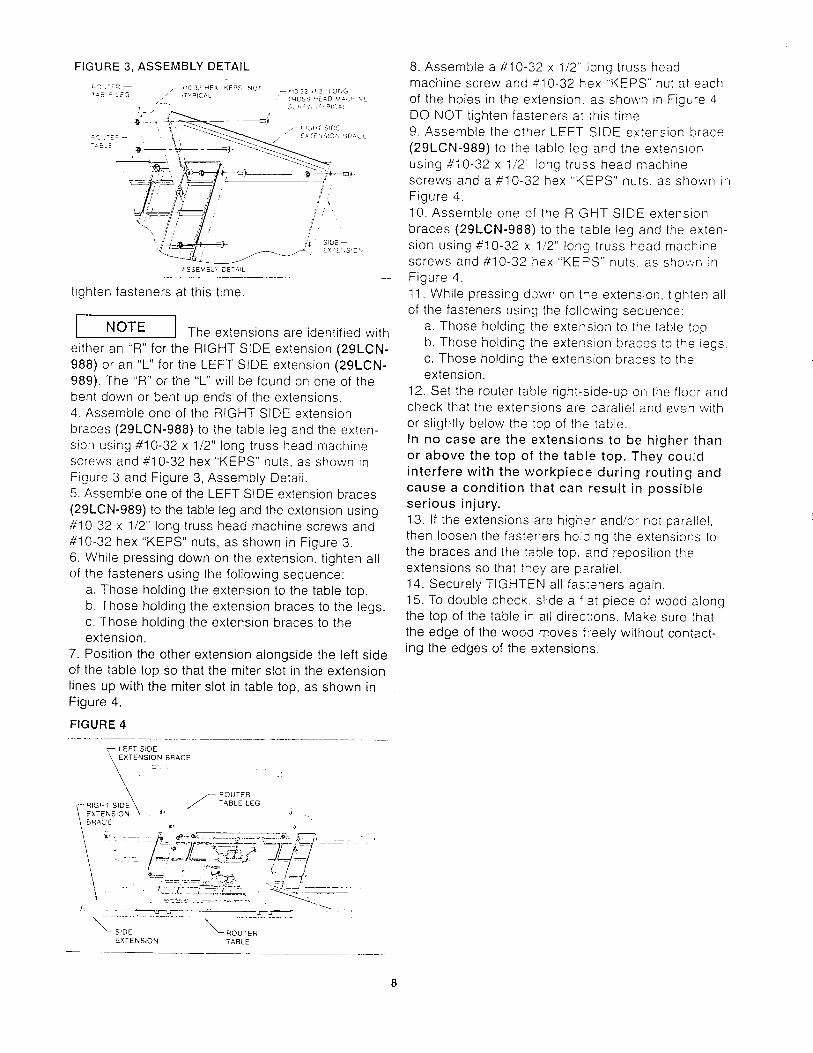
FIGURE 3, ASSEMBLY DETAIL
ASSEMBLY CETAL
tighten fasteners at this time.
I I The extensions are identified withINOTE
either an "R" for the RIGHT SIDE extension (29LCN-
988) or an "L" for the LEFT SIDE extension (29LCN-
989). The "R" or the "L" will be found on one of the
bent down or bent up ends of the extensions.4. Assemble one of the RIGHT SIDE extension
braces (29LCN-988) to the table leg and the exten-
sion using #10-32 x 1/2" long truss head machinescrews and #10-32 hex "KEPS" nuts, as shown in
Figure 3 and Figure 3, Assembly Detail.5. Assemble one of the LEFT SIDE extension braces
(29LCN-989) to the table leg and the extension using#10-32 x 1/2" long truss head machine screws and
4'10-32 hex "KEPS" nuts, as shown in Figure 3.
6. While pressing down on the extension, tighten all
of the fasteners using the following sequence:
a. Those holding the extension to the table top.
b. Those holding the extension braces to the legs.
c. Those holding the extension braces to theextension.
7. Position the other extension alongside the left side
of the table top so that the miter slot in the extension
lines up with the miter slot in table top, as shown in
Figure 4.
FIGURE 4
8. Assemble a #<10-32 x 1/2" long truss headmachine screw and _'10-32 hex "KEPS" nut at each
of the holes in the extension, as shown in Figure 4.
DO NOT tighten fasteners at this time.9. Assemble the other LEFT SIDE extension brace
(29LCN-989) to the table leg and the extension
using #10-32 x 1/2 long truss head machine
screws and a #10-32 hex "KEPS" nuts, as shown in
Figure 4.10. Assemble one of the RIGHT SIDE extension
braces (29LCN-988) to the table leg and the exten-
sion using #10-32 x 1/2" long truss head machinescrews and #10-32 hex "KEPS" nuts. as shov,.n in
Figure 4.
11. While pressing down on ti_e extension, tighten all
of the fasteners using the following sequence:
a. Those holding the extension to the table top.
b. Those holding the extension braces to the legs.
c. Those holding the extension braces to theextension.
12. Set the router table right-side-up on the floor and
check that the extensions are parallel and even with
or slightly below the top of the table.
In no case are the extensions to be higher than
or above the top of the table top. They could
interfere with the workpiece during routing and
cause a condition that can result in possible
serious injury.
13. If the extensions are higher and!or not parallel.
then loosen the fasteners hoi0ing the extensions to
the braces and the table top. and reposition the
extensions so that they are parallel.
14. Securely TIGHTEN all fas:eners again.
15. To double check, slide a fat piece of wood alongthe top of the table in all directions. Make sure that
the edge of the wood moves freely without contact-ing the edges of the extensions,

THE FLOOR STAND AND THE ROUTER TABLE
As can be seen in the LEGNOTE
ILLUSTRATION, there are four holes along theedges of the leg. These are for use on a futureaccessory product for the floor stand.
LEG ILLUSTRATION
ACCESSORYHC=ES
r
ACCESSORY
,J HOLES
J/JJ
i -_/ /
//
/-
./
° l
. /
.g/Z
The following procedure is easier to carry out if twopeople perform the task.
1. Lay the shelf, top side down, on a workbench orother sturdy surface, so that two of the corners alongthe long length of the shelf overhang the workbench,as shown in Figure 5.
I I The placement of a weight on theINOTE
shelf, as shown in Figure 5, is strongly recommendedso that the shelf will maintain its position on the work-bench and will not tip and fall off the workbench whileassembling the legs to the shelf.
FIGURE 5
-- "10 32 X " 2" _ONG
Tquss _E_'D MACHINE
SCREW _,CAL)WORKBENCH_ ............. ,
/ -- "!032 HEX ,',EroS- NUT
'TYPICAL_
PLACE _WEIGHT _-
_r _.... - -- FLOOR
....... r , _. "" STAND LEG
SHELF
_LOOR
2. Assemble a leg to one of the corners of the shelf
using four #10-32 x 1/2" long truss head machinescrews and #10-32 hex KEPS" nuts, as shown in
Figure 5.
3. Assemble a second leg in the same manner,
4. Lay the partially assembled floor stand on its side
on the floor so that the legs support the floor stand.
as shown in Figure 6.
FIGURE 6
;_C3 P_S-._'4- -- -
S I
TRU'_S HEAD LtAC_ ",E '\ '_o /..... ".L./
/
• 10 32 HEX KE_S X_T _/
_TYRICAL) z- LOWER' SHELF
C/
"k_FLOO,
5. Assemble the remaining legs to the shelf usingfour//10-32 x 1/2" long truss head machine screwsand #10-32 hex "KEPS" nuts, as shown in Figure 6.
6. SECURELY TIGHTEN ALL FASTENERS.
7. Assemble a leveling foot to each of the levelingbrackets, as shown in Figure 7.
FIGURE 7
!f
LEVELING
r_ /_/ BRACKET
t
\
t
8. Assemble the leveling brackets to each of thefloor stand legs using three #10-32 x 1/2" long trusshead machine screws and three #10-32 hex "KEPS"nuts, as shown in Figure 8.

FIGURE 8
_E_ELINGLEVEL!NG //-- _,:©_
" _"_ _ ":C 32 × ! 2 -C';G
j_'["Sg_E,',
,1032 HEX KEPS _'_gT_'_'i -_ .
:" .::, :..%
FLOOR STAND LEG\ 4',
\
9. Set the router table top side down on the floor as
shown in Figure 9. At this stage in the procedure,
employing a second person to aid you in holding
the router table and the floor stand in place is
strongly recommended•
FIGURE 9
LOWER
• , ,._ SHELF , . _ - :_r2OR _<T-_'ID LEG
• i
• • * -- :'0 32 _E: _, KEPS NUT
." . T,,p_CL L
), //--:uPPER SHELF,_ t * /
"".._ _ =:O 32 X i 2 LONG
- / TqUSS HEAD MACHh"4E SC_E,',
• [ TYPICAL
_, _ ,,_ ROUTER TABLE LEG
ROCTEB TABLE_ _ "_ S,',:TC _
10. Position the floor stand on the router table legs,as shown in Figure 9.
11. Set the upper shelf on the floor stand legs, asshown in Figure 9.
12. Line up the holes in the floor stand leg and theupper shelf with the corresponding holes in the routertable legs.
I I Inserting a nail with a large headINOTE
through one of the holes at each of the four cornersof the lower shelf will aid you in maintaining partalignment. (The truss head machine screws mayalso be used.) The nails (or screws) are removedfrom the holes when the truss head machine screwsare assembled as described in the next step.
It may be necessary, to loosen the fasteners holding
the legs to the table in order to make the holes in
table legs line up with the holes in the shelf and theholes in the floor stand legs. and so the table legs
can be made to lie fiat on the floor stand legs.
13. Assemble a ,_I0-32 x 1/2" long truss headmachine screw and #10-32 hex "KEPS" nut at each
of the holes, as shown in the Figure 9, AssemblyDetail. ORIENTATION OF THE FASTENERS MUST
BE AS SHOWN.
FIGURE 9, ASSEMBLY DETAIL
//./"
f'" _ =_ 12 _, <E_a - -
._ //- _ :.C._ _
• /
e ,
__- .. . .
UPPER S_EL_ _
_LCOR STANC -E2_
_._f/ '¢_:- ".E _ Z:E.'.
:_E"-2_- 2--: L _E.2
14. SECURELY TIGHTEN ALL FASTENERS.
INCLUDING THOSE HOLDING THE LEGS TO THE
ROUTER TABLE.
15. Set the floor stand right side up on the floor, as
shown in Figure 10.
FIGURE 10
16. Adjust the leveling feet by:
a. loosening the screws holding leveling bracketto leg,b. adjusting the height,c. retightening the screws until the floor stand isfirmly supported by the floor and does not rockback and forth.
17. It may be necessary for you to do this any timethe floor stand and router table are moved.
10
18.Checkthattheextenstonsareparallelandevenwith.orslightlybelow,thetopof thetable.
19.[A }[,,_ WARNINGj In nocasearetheextensionsto behigherthan.orabove,thetopof thetabletoporelsetheymayinterferewiththeworkpieceduringrouting.Thiscouldcausea conditionthatcanresultinpossibleseriousinjury.20. If theextensionsarehigherand/ornotparallel.thenloosenthefastenersholdingtheextensionstothebracesandto thetabietop.andrepositionthemuntiltheyareparallel.2I. SECURELYTIGHTENALLFASTENERSAGAIN.22.Todoublecheck,slidea flatpieceofwoodalongtopoftheroutertableinalldirections.Makesurethattheedgeof thewoodmovesfreelywithoutcon-tactingtheedgesoftheextensions.
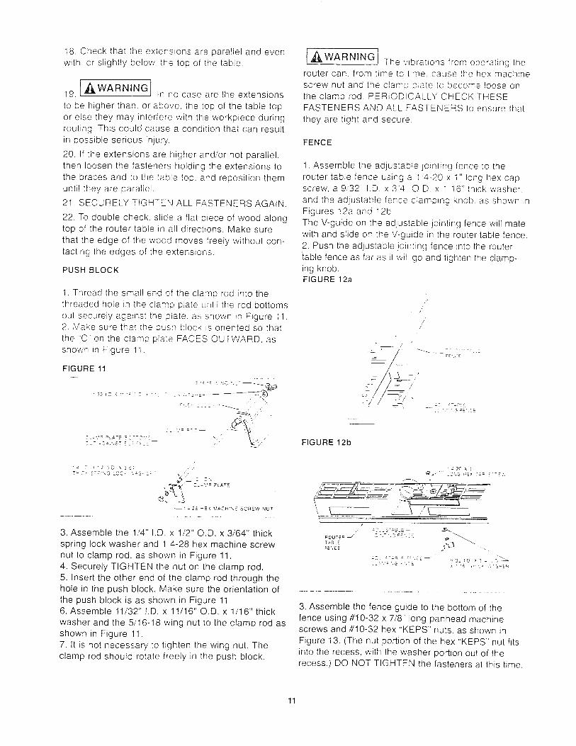
PUSHBLOCK
1.Threadthesmallendoftheclamprodintothethreadedholein theclampplateuntiltherodbottomsoutsecurelyagainsttheplate,asshowninFigure11.2. Makesurethatthepushblockisorientedsothatthe 'C ontheclampplateFACESOUTWARD,asshowninFigure1t.
FIGURE 11
"'22!DX:'": 27 ' "'4 -- --< .'.a3--_-=__'_
2_-". '= -*':._.TE -2--2".'£ ,..Z-- :_-" NST -:_:::EE
T_ C- _='_ ",G LQC* .'._-S-E:-- ,,,<,;
t4 2_. -E'( MACH:X-_- SCREW NUT
3. Assemble the 1,/4'. I.D. x 1/2" O.D. x 3/64" thick
spring lock washer and 1 4-28 hex machine screw
nut to clamp rod. as shown in Figure 11.
4. Securely TIGHTEN the nut on the clamp rod.
5. Insert the other end of the clamp rod through thehole in the push block. Make sure the orientation of
the push block is as shown in Figure 11.6. Assemble 11/32" I.D. x 11/16" O.D. x 1/16" thick
washer and the 5/16-18 wing nut to the clamp rod asshown in Figure 11.
7. It is not necessary to tighten the wing nut. Theclamp rod should rotate freely in the push block.
{,_WARNING The v{brations from operating the
router can, from time to t_me. cause the hex machine
screw nut and the clamp plate to become loose on
the clamp rod. PERIODICALLY CHECK THESEFASTENERS AND ALL FASTENERS to ensure that
they are tight and secure
FENCE
1. Assemble the adjustable jointing fence to the
router table fence using a 1'4-20 x 1" long hex capscrew, a 9'32" I.D x 34 O.D. x 1 16" thick washer.
and the adjustab!e fence clamping knob. as shown in
Figures 12a and 12b
The V-guide on the adjustable jointing fence will matewith and slide on the V-guide in the router table fence.
2. Push the adjustable jointing fence into the router
table fence as far as _twill go and tighten the clamp-
ing knob.FIGURE 12a
/
/
'&_-7
a7. _-a_LE
FIGURE 12b
"z2CX:
', \ ,,' \ ,
/
_' _Z'.-'.S =£',7B o- _"_,ROU*_Eq
TABLE _FEr;CE L >_
[-:'.'= ',G -',i-' ' _B 7_ Z" .'.ZB"_ER
3, Assemble the fence guide to the bottom of the
fence using #10-32 x 7/8" long panhead machinescrews and #10-32 hex "KEPS" nuts. as shown in
Figure 13. (The nut portion of the hex "KEPS" nut fits
into the recess, with the washer portion out of therecess.) DO NOT TIGHTEN the fasteners at this time.
11

FIGURE 13
\,/
NOTE ORIENTATION OF
,O GROOVE IN FENCE
SURFACE OF FENCE GUfDE " \, GUIDE
MUST BE FLUSH WITH _ \_BACK SURFACE OF ROUTER ' '_ FENCE GUIDE
TABLE FENCE
_'10 32 HEX 'KEPS NUT
FIGURE 14b
-- RCLTE q
--- "P:i / FENCE
4. To align the fence, position the fence on the routertable so that the fence guide fits in the channels inthe top of the table, as shown in Figure 14a.5. Insert a 1/4-20 x 1-3/4" long round headsquare neck bolt, from the underside of thetable, through the slot in the fence, as shown inFigure 14a.
FIGURE 14a
F El'ICE C L_ !,lPrNO
KNOB9,32 :D X34OD Xll£ _321D X34OD Xt:6
TH!CK WASHER THICK WASHER
",, X
, \ '
E:U'DEJ 11" SCREWSCHANNEL 154
4 20 X 13 4- LONG ROUND ROUTER TABLE '_\
HEAD SQUARE NECK BOLTx
i 4 2c x t 3 4 LONG ROUND
HEAD SQUARE NECK BOLT
6. Place a 9/32" !.D. x 3/4" O.D. x 1/16" thick washerover the bolt, as shown in Figure 14a.7. Lightly thread a fence clamping knob onto the bolt.DO NOT TIGHTEN clamping knob at this time --fence must be able to MOVE FREELY from front toback on the table.8. Repeat Steps 5 through 7 for the other side of thefence.9. Make sure that the adjustable jointing fence isinside the router table fence as far as it will go andthat the clamping knob has been securely tightened•10. Line up the front of the fence with the "0" markson the top of the router table, as shown in Figure 14b.11. TIGHTEN the fence clamping knobs MAKINGSURE THAT THE FENCE DOES N©T MOVE.12. TIGHTEN the two #10-32 x 7/8" long panheadscrews to secure the fence guide to the fence, asshown in Figure 14a.
13. Remove the fence from the table by unthreadingthe fence clamping knobs from the 1/4-20 x 1-3/4"long round head square neck bolts while holding thebolts in place from the underside of the table.14. Remove the 9!32" I.D. x 3/4" O.D. x 1/16" thickwashers from the bolts and then remove the bolts.
15. Store fasteners in a cor:venient place so theycan be used at later time.16. Assemble the overhead guard to the router tablefence using two 14" pushnLts and the 1/4" O,D. x2-11/16" long overhead guard pivot pin, as shown inFigure 15:
FIGURE 15
OVERHEAD GUARD
PP,IOT PIN-- D'.ERHEAD GL'_=D
• 4 PUSHNUT--
t
l_ '_'_ ROUTER TABLE
ROUTER TABLE FENCE--
a. Press one of the pushnuts onto one end of thepivot pin. (It will be necessary to tap the pushnutonto the overhead guard pivot pin with a hammerwhile supporting the other end of the overheadguard pivot pin.)b. Position the overhead guard on the fence sothe holes in the overhead guard line up with thethrough-hole in the router table fence• MAKESURE THE ORIENTATION OF OVERHEADGUARD ISAS SHOWN IN FIGURE 15.c. Insert the overhead guard pivot pin through thealigning holes.
12

d. Press the second pushnut onto the other end ofthe overhead guard pivot pin in the same manneras in Step a.e. Move the overhead guard up and down a fewtimes to ensure that it moves freely.
tA/LLLWARNING J Once the overhead guard has
been assembled to the fence, DO NOT remove it forany reason. Its removal can result in an unsafe oper-ating condition that can result in possible bodily injury.
PUSH BLOCK ASSEMBLY TO THE ROUTER TABLE
FENCE
FIGURE 16
1. Position the clamp plate relative to the push block,as shown in Figure I6.2. Align the rib and the V-shaped portion of the pushblock with both the groove in the front of the fenceand the V-shaped portion of the fence.3. Assemble the push block to the fence as shown inFigure 16. The push block should move freely along thefull length of the fence when the guard is in the UPposition.
NOTE J
1. It is a good practice to frequently remove the dustand chips that accumulate in use from the slidingsurfaces of the fence and the push block, and fromthe groove in the fence.2. The occasional application of a very light coatingof furniture wax to the SLIDING SURFACES ONLY,of the push block, will improve the sliding action.
MITER GAUGE
1. Assemble the protractor head to the miter bar, as
shown in Figure 17. using a #10-32 x 1/2" long trusshead machine screw.
FIGURE 17
"0 32 X ' 2- LCNG
._S -'qUSS "EA3 MACMr-,E SCP_E¢,
M_TER BA,q- --USE -_'2 '40LE
i "'o o ,.j>
NOTE ] There are two round holes in the
miter bar. Make sure the truss head screw enters the
correct hole shown.
2. Tighten truss head screw into the protractor head
so that the wcrew head just touches the miter bar but
still provides a resistance when the protractor headis rotated.
3. Assemble the knob, the 3/16" I.D. x 9/16" O.D. x
.040" thick washer and the #10-24 x 3/4" long round
head square neck bolt to the miter bar and protractor
head, as shown in Figure !8.
FIGURE 18
KNOB _ _%//--
_1_ :4 40 X 3 4" LONG
=JNHEAD MACHINE SCREW
3:16"1.D X 9:16"O D _ _/,,_-,X .040- THICK WASHE= _
,,-7%-
i r4 40 HEX
Tg%gg¢oSOUARE
4. Assemble the miter pointer to the miter bar usingthe #4-40 x 3/4" long panhead machine screw andthe #4-40 hex machine screw nut. Make sure the
miter pointer POINTS in the right direction.5. TIGHTEN screw and nut SECURELY
13
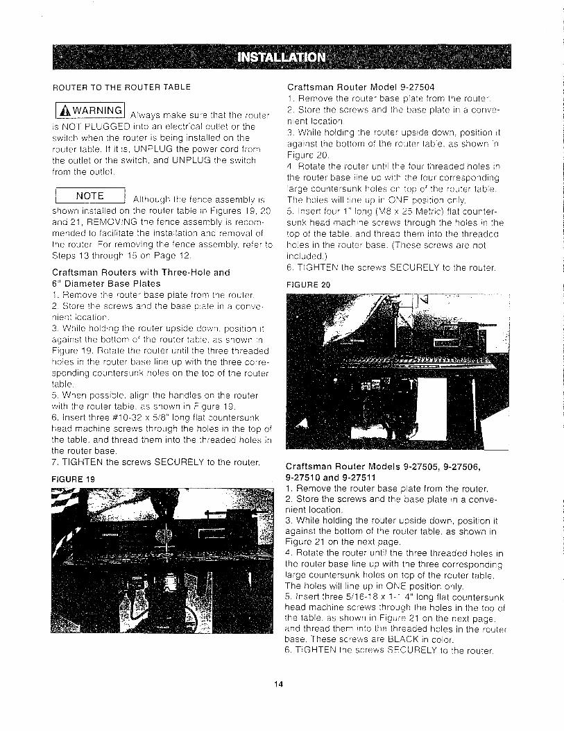
ROUTER TO THE ROUTER TABLE
[,_WARNING] Always make sure that the router
is NOT PLUGGED into an electrical outlet or the
switch when the router is being installed on the
router table. If it is, UNPLUG the power cord fromthe outlet or the switch, and UNPLUG the switch
from the outlet.
l J Although the fence assembly Js]NOTE
shown installed on the router table in Figures 19, 20
and 21, REMOVING the fence assembly is recom-mended to facilitate the installation and removal of
the router, For removing the fence assembly, refer to
Steps 13 through 15 on Page 12.
Craftsman Routers with Three-Hole and
6" Diameter Base Plates
1. Remove the router base plate from the router.
2. Store the screws and the base plate in a conve-nient location.
3. While holding the router upside down. position it
against the bottom of the router table, as shown in
Figure 19. Rotate the router until the three threaded
holes in the router base line up with the three corre-
sponding countersunk holes on the top of the routertable.
5. When possible, align the handles on the router
with the router table, as shown in Figure 19.
6. Insert three #10-32 x 5/8" long flat countersunk
head machine screws through the holes in the top ofthe table, and thread them into the threaded holes in
the router base.
7. TIGHTEN the screws SECURELY to the router.
FIGURE 19
Craftsman Router Model 9-27504
1. Remove the router base plate from the router.
2. Store the screws and the base plate in a conve-nient location.
3. While holding the router upside down, position it
against the bottom of the router table, as shown in
Figure 20.4. Rotate the router until the four threaded holes in
the router base line up with the four corresponding
large countersunk holes on top of the router table.
The holes will line up in ONE position only.
5. Insert four 1" long (M8 x 25 Metric) flat counter-
sunk head machine screws through the holes in the
top of the table, and thread them into the threaded
holes in the router base. (These screws are not
included.)6. TIGHTEN the screws SECURELY to the router.
FIGURE 20
Craftsman Router Models 9-27505, 9-27506,9-27510 and 9-275111. Remove the router base plate from the router.2. Store the screws and the base plate in a conve-nient location.3. While holding the router upside down, position itagainst the bottom of the router table, as shown inFigure 21 on the next page.4. Rotate the router until the three threaded holes inthe router base line up with the three correspondinglarge countersunk holes on top of the router table.The holes will line up in ONE position only,5. Insert three 5/16-18 x 1-1 4" tong flat countersunkhead machine screws through the holes in the top ofthe table, as shown in Figure 21 on the next page,and thread them into the threaded holes in the routerbase. These screws are BLACK in color.6. TIGHTEN the screws SECURELY to the router.
14

FIGURE21
Other Brands of RoutersIt will be necessary for you to purchase aCraftsman Professional Router Adapter Plate,(9-25333), from your local Sears Retail Outlet orthrough the Sears Catalogue.Routers with a total overall height of 13 inches orless and a base diameter of 7 inches or less can beaccommodated.
ROUTER POWER CORD TO THE SWITCH
,_.WARNING
• Make sure that the power cord from the switch box
IS NOT PLUGGED into an electrical outlet while per-
forming the following tasks. If it is plugged in.UNPLUG it.
o MAKE SURE THAT ROUTER SWITCH IS IN THE
OFF pOSITION.
1. Plug the router power cord into one of the outletson the switch box.
2. Form the excess power cord into a coil.
3. Wrap two pieces of friction tape or strong cordaround the coil at opposite sides of the coil.
4. Allow some slack so that the cord does notbecome stretched when it is plugged into the switchbox.
5. If desired, at this time plug the power cord from an
accessory, such as a web'dry vac or light, into theother outlet.
[ ,WARNING]• DO NOT plug the power cord from the router intoan electrical outlet AT THIS TIME.
• It WILL be necessary to use an extension cordbecause of the short cord on the switch box. Refer
to the upcoming section. ELECTRICAL REQUIRE-MENTS, under USING THE SWITCH for cord
specifications.
• Make sure that power cords from the router, acces-
sories, the switch box. and the extension cord DONOT and CANNOT COME IN CONTACT with the
router or any moving parts of the router.
° Make sure that power cords from the router, acces-sories, the switch box, and the extension cord D©
NOT and CANNOT INTERFERE with any routing
operation or come in contact with the workpiece.
-. The power cord from the router is to be plugged
into the electrical outlet only AFTER the setup for
your routing operation has been completed.
• Refer to the upcoming section. SWITCH BOX
OPERATION. on Page 18.
• Refer to the upcoming section. USING THE
ROUTER TABLE. on Page 20_
15
FENCE TO THE ROUTER TABLE
1. Refer to Steps 4 through 8 and Figure !4a onPage 12.
2. Adjust fence to desired location to obtain requiredcut.
NOTE I
There are two scales, with 1/16" increments, moldedinto the top of the router table to aid you in adjustingthe location of the fence.
4. TIGHTEN the knobs when the fence assembly is
aligned at the desired location.
WET/DRY VAC TO THE FENCE
The router table fence assembly has a port at theback where a wet/dry vac hose can be connected.
The port will accommodate a 2-1/2" diameter hosenozzle.
To attach, push the nozzle into the port while holding
the fence in place.
,_CAUTION I
Operating the router table without a wet/dry vac canresult in an excessive collection or build-up of saw-dust and chips under the fence assembly and theoverhead guard. This can hinder the performance ofthe router table and the fence assembly.
RECOMMENDATION: Regardless of whether awet/dry vac is being used, remove the sawdust andwood chips from under the fence assembly and theoverhead guard as needed. This removal should bedone so that the performance of either is not hin-dered.
RECOMMENDATION: It is always a good practice tokeep the work area clean. As necessary, remove thesawdust and wood chips from the top of the routertable, as well as any that has accumulated on thefloor around the router table.
,_WARNING
When doing the above, keel_ the following in mind:oThe ROUTER and THE SWITCH must be turnedOFF.
o The router bit must NOT be turning.• The router power cord must be UNPLUGGEDfrom the switch.• The power cord from the switch must beUNPLUGGED from the extension cord.
16

TABLE TOP INSERTS TO THE ROUTER TABLE
This router table comes with three table top inserts inthe following hole sizes:
o 1-1/4" diameter, for use with router bits with diame-ters up to 1-1/8"
• 1-7/8" diameter, for use with router bits with diame-ters up to 1-3/4"
o 2-1/8" diameter, for use with router bits with diame-ters up to 2"
• For router bits with diameters between 2" and 2-3/4"
the table top inserts are not used. See Figure 22.
FIGURE 22
I,_WARNINGJ A 2-3/4" diameter router bit is the
LARGEST router bit that can be SAFELY used on
this router table.
1. Select the table top insert that accommodates therouter bit to be used.
2. Assemble the insert to the table top by pressing itinto the large hole in the top of the router table, asshown in Figure 23.
3. Press down equally over the tabs on the insert sothat the tabs snap into place.
4. To remove, insert a finger in the insert hole andgently pull up until the tabs disengage the hole.When not in use. store the inserts in a convenientplace.
[,_WARNING] DO NOT attempt to remove insert
from the table top unless the router bit has beenremoved from the router.
FIGURE 23
17
GENERAL
The Power Switch is designed to be used with mostCraftsman Router Tables and Routers. It provides theconvenience of an ON-OFF switch at the front ofthe table, thus eliminating the need to reach under-neath the table to turn the router ON and OFF.
I NOTE I The electronic routers (9-1750
and 9-27501) are a special case which is explainedin the section ROUTER AND SWITCH BOXOPERATION.
The Power Switch also provides an optional simulta-neous ON-OFF control of an additional accessory,such as a light, vacuum, etc. The switch incorporatesan internal, resettable circuit breaker to provide pro-tection in overload situations.
ELECTRICAL REQUIREMENTS
In the event of a malfunction or breakdown, ground-ing provides the path of least resistance for electriccurrent in order to reduce the risk of electric shock.This switch box is equipped with an electric cord thathas an equipment grounding connector and agrounding plug. The plug must be plugged into amatching outlet that is properly installed and ground-ed in accordance with all local codes and ordinances.
DO NOT modify the plug provided if it will not fit theoutlet. Have the proper outlet installed by a qualifiedelectrician.
Improper connection of the equipment grounding con-ductor can result in risk of an electric shock. The con-ductor with insulation that has a green outer surface,with or without yellow stripes, is the equipmentgrounding conductor. If repair or replacement of theelectric cord or plug is necessary, DO NOT connectthe equipment grounding conductor to a live terminal.
Check with a qualified electrician or service person ifthe grounding instructions are not completely under-stood, or if there is doubt as to whether the switchbox is properly grounded.
Use only 14 gauge, or larger, three-wire extensioncords that have three-prong grounding plugs andthree-hole receptacles that accept the tool's plug.
Repair or replace a damaged or worn cord immediately.The electrical outlet on the back of the switch box
will accept either a two-prong plug from a DOUBLEINSULATED router or accessory, or a three-pronggrounding type plug.
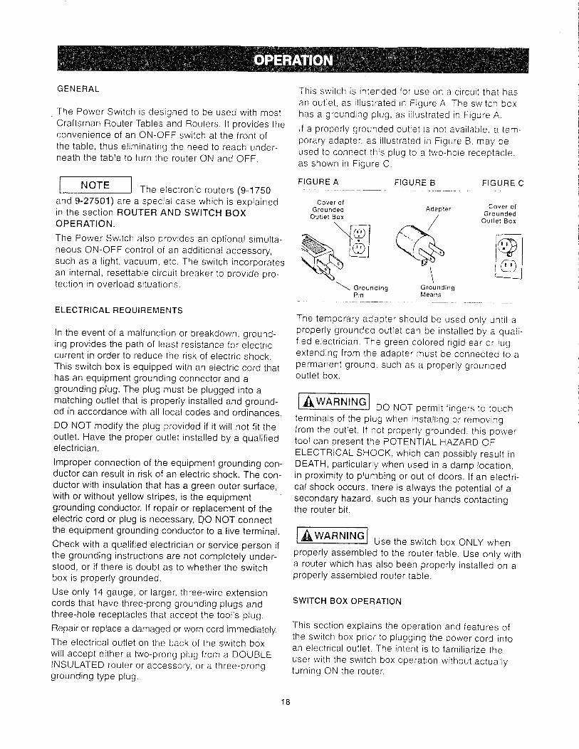
This switch is intended for use on a circuit that hasan outlet, as illustrated in Figure A. The switch boxhas a grounding plug, as illustrated in Figure A.
If a properly grounded outlet is not available, a tem-porary adapter, as illustrated in Figure B. may beused to connect this plug to a two-hole receptacle.as shown in Figure C.
FIGUREA FIGURE B FIGURE C
Cover ofGrounded Adapter Cover of
_ Grounding Grounding
Pin Means
The temporary adapter should be used only until aproperly grounded outlet can be installed by a quali-fied electrician. The green colored rigid ear or lugextending from the adapter must be connected to apermanent ground, such as a properly groundedoutlet box.
[,_WARNING DO NOT permit fingers to touch
terminals of the plug when installing or removingfrom the outlet. If not properly grounded, this powertool can present the POTENTIAL HAZARD OF
ELECTRICAL SHOCK, which can possibly result inDEATH, particularly when used in a damp location,in proximity to plumbing or out of doors. If an electri-cal shock occurs, there is always the potential of asecondary hazard, such as your hands contactingthe router bit.
['_WARNINGI Use the switch box ONLY when
properly assembled to the router table. Use only witha router which has also been properly installed on aproperly assembled router table.
SWITCH BOX OPERATION
This section explains the operation and features of
the switch box prior to plugging the power cord intoan electrical outlet. The intent is to familiarize the
user with the switch box operation without actuallyturning ON the router.
18

Theswitchboxincorporatestwopositivesafetyfea-turesto preventinadvertentswitchingONof therouterandtheunauthorized,andpossiblyhazardous,usebyothers.InadvertentswitchingONof therouteris preventedbytheclearplasticswitchcover.Thecovermustberaisedandtheswitchmanuallytog-gledto theONpositionto starttherouter.Also,thesafetykeycanbe removedto disabletheswitchboxby"locking"theswitchin theOFFposition,thuspre-ventingunauthorizedandpossiblehazardoususe.Inanemergency,theswitchcanbeturnedOFFbyslappingorstrikingtheswitchcoverwiththehand.Tooperatetheswitchbox.proceedasfollows:
l Because the switch also func-NOTE
tions as a circuit breaker, the ON position is labeledRESET on the switch. For clarity this instruction usesON in place of RESET.
1. Insert the safety key into switch box. See Figure 24.
FIGURE 24
2. To turn router ON, insert finger under switch coverand toggle switch to ON position.
3. To turn router to OFF, press switch cover.
NEVER leave router UNATTENDED until it hascome to A COMPLETE STOP.
4. To lock switch to OFF position, remove key fromswitch-box.
With the key removed from the switch box, theswitch cannot be toggled to the ON position.
I,_WARNINGJ Before proceeding any further,make sure the switch on the router is in the OFF
position and the switch lever is in the OFF position.
The switch box power cord can now be plugged intoa wall outlet.
ROUTER AND SWITCH BOX OPERATION
This section explains operation of the switch boxwith the power cord plugged into an electrical outlet.The router will turn ON when the switch is tog-gled to the ON (or RESET) position.
1. Position the ON-OFF switch on the router in the
ON position. On certain routers this will require theuse of the Switch Trigger and "LOCK-ON" button.(Consult router owner's manual.) Make sure theswitch box lever is in the OFF position whendoing this.
2. To turn the router ON, slide finger under theswitch cover and toggle the switch to the ON posi-tion. as described in the previous section.
3. To turn the router OFF. press the switch cover, asdescribed in the previous section.
SPECIAL NOTE TO OWNER'S OF MODELS
NOS. 9-1750 AND 9-27501 ROUTERS
Because these routers come with a special "LOCK-
ON feature that will not permit it to be turned ON by
the switch box (but allow router to be turned OFF by
the switch) the following method of operation is tobe used:
1. Toggle the switch box switch, as described in the
previous section. The router should NOT start even
though the trigger lock is in the "LOCK-ON" position.
(Consult router owner's manual.)
2. To start the router, depress the trigger and
engage the LOCK-ON button located on the side ofthe handle. THE ROUTER SHOULD START IMME-
DIATELY.
If the router switch is already in the "LOCK-ON" posi-tion (The "soft" and "1/4 inch" indicator lights will beflashing - consult router owner's manual), unlock thetrigger. Depress the trigger, and THE ROUTERWILL START IMMEDIATELY. Engage the "LOCK-ON" button on the side of the handle.
3, To turn the router OFF, press the switch boxswitch cover.
4. To restart the router, it will always be necessary to
perform Step 1 through Step 2.
I t In the event of an overload situa-INOTE
tion, the internal switch box circuit breaker may tripand toggle the switch to the OFF position. This willinterrupt the power to the router and/or vacuum. Ifthis occurs please do the following:
1. Unplug the switch box cord from the electrical outlet.
2. Clear the workpiece from the router table.
19

3. Correct the cause of the overload situation (i.e.the removal of too much stock or use of too high afeed rate).
4. Plug the switch box power cord into the electricaloutlet.
5. Restart the router as described in the sectionROUTER AND SWITCH BOX OPERATION on
Page t 9.
[,_WARNING] For your own SAFETY and the
SAFETY OF OTHERS, do the following when therouter table is not in use:
1. Toggle the switch lever to the OFF position andremove the key.2. Turn the router OFF.
3. Unplug the switch box power cord from the electri-cal outlet.
4. Remove the router bit from the router.
5. Make sure the router collet assembly is below thetop of the router table.
6. Store the switch box key in a safe location whereit is not available to children or other unauthorized
persons.
['_WARNINGI In the event of a power failure.
blown fuse, or router "stalling out while routing, pushthe switch cover to toggle the switch to the OFFposition and remove the key from the switch boxuntil the source of the problem has been corrected.In addition, UNPLUG the switch box from the electri-cal outlet.
USING THE ROUTER TABLE
[,_WARNING 1 BEFORE each and every use,make sure that the floor stand is STABLE on thefloor and DOES NOT rock back and forth. If it does.level the floor stand as described in a prior section.
The adjustable fence on your table is provided as aguide against which the workpiece should be held foraccuracy in routing. FREE HAND ROUTING (notholding work against the fence) is HAZARDOUS andshould be STRICTLY AVOIDED without pilotedrouter bits.
2O

ROUTING USING THE FENCE WITHOUT THE
PUSH BLOCK
Full Edge Cutting:For maximum strength and accuracy, boards to bejoined together should be smooth and true. The edgesshould be true to the workpiece surface. You can truethe edges on your router table using a straight bit.
1. Check to see if face of adjustable jointing fence isflush with the face of the router table fence. If not,loosen adjustable fence clamping knob on jointingfence and adjust. Tighten the fence clamping knobon the adjustable fence.
I J The adjustable jointing fence pro-]NOTE
vides a continuous support for the workpiece as it isfed beyond the router bit. The adjustable jointingfence compensates for the gap created after theremoval of material by the router bit.
2. Adjust depth of cut (the material you want toremove) and router bit height as described in Steps1 - 4. ADJUSTING DEPTH AND HEIGHT OF THECUT on Page 20. Tightly secure the fence and therouter as described before. (Make sure router isUNPLUGGED when making adjustments.)
3. LOWER THE OVERHEAD GUARD to the operat-ing position. (Overhead guard shown raised for rea-sons of clarity.)
4. Check your adjustments by turning the router ON,using the switch, and feeding a piece of scrap wooda few inches beyond router bit. Then stop and turnrouter OFF, using the switch.
I I Feed work AGAINST the rotationINOTE
of the cutter (in the direction shown by arrow inFigure 26).
FIGURE 26
5. Loosen the fence clamping knob on theadjustable jointing fence and move it out, flushagainst the finished edge of scrap wood. Retightenthe knob. See Figure 26.6. Repeat the test cut on the scrap wood with over-head guard DOWN.7. The router table is now ready for use.
I J For best results when jointing,]NOTE
take very shallow cuts, !/32" or less.
Edge Cutting With Non-Piloted Router Bits:1. Position the adjustable jointing fence so that its faceis flush with the face of the table fence. Tightenadjustable fence clamping knob on jointing fence. SeeFigure 27.2. Adjust depth of cut (material you want to remove)and router bit height, as described previously inADJUSTING DEPTH AND HEIGHT OF THE CUT,Steps 1 - 4 on Page 20. Tighten both fence clampingknobs to lock fence on table. Tightly secure therouter. (Make sure router is UNPLUGGED whenmaking adjustments.)3. LOWER THE OVERHEAD GUARD to the OPER-ATING POSITION. Overhead Guard shown raised for
reasons of clarity.4. Test cut a piece of scrap wood to make sureadjustments are satisfactory.
I NOTE J Feed work AGAINST the rotation]
of the cutter (in the direction shown by the arrow inFigure 27).5. The router table is now ready for use.
FIGURE 27
Overhead Guard shown raised for reasons of clarity.
21
Overhead Guard shown raised for reasons of clarity.

Edge Cutting With Piloted Router Bits:1. Position the fence in the same manner as with
non-piloted bits.
2. Move the fence back only enough to permit the
pilot to control the cutting depth• Positioning the fence
as close to the pilot as possible will serve as a back-
up and will help to prevent chances of an accident
and possible personal injury. See Figure 28.3. LOWER THE OVERHEAD GUARD to the OPER-
ATING POSITION. Overhead guard shown raised for
reasons of clarity.
4. Test cut a piece of scrap wood to make sure
adjustments are satisfactory.
NOTE J Feed work AGAINST the rotationI
of the cutter (in the direction shown by the arrow inFigure 28).5. The router table is now ready for use.
FIGURE 28
Overhead Guard shown raised for reasons of clarity.
Grooving, Fluting, And Veining:Always UNPLUG the router before making anysettings, adjustments, or changing bits.
When routing, always FEED AGAINST the rotationof the cutter. Feed workpiece in the direction ofarrow, as in Figure 28.
For maximum accuracy, one edge of your workpiece(edge sliding against the fence) must be true andstraight. Set up your fence as follows:1. Position the fence behind the router bit for thedesired cutting depth (the distance of the cut fromthe edge of the workpiece, as shown in Figure 29).Make sure the overhead guard is in place as shown.
2. Securely TIGHTEN both knobs.
3. Make the cut by sliding the straight edge of workpieceagainst the fence, as shown in Figure 30 (For eachsuccessive cut, the fence would need to be readjusted.)
FIGURE 29, VIEW FROM LEFT SIDE OF ROUTER
NOTEI Test cut a piece of scrap wood
before making your finish cut. Feed workpiece in the
direction of arrow. (Refer to Figure 30.)
FIGURE 30
I I When routing deep cuts (con-INOTE
trolled by router bit) in a workpiece, remove a small
amount of material to prevent your router from over-
loading. Repeat operation with several gradually
deeper passes until the desired depth is achieved.
END CUTTING USING THE FENCE WITHTHE PUSH BLOCK
I,_WARNINGJ End cutting is performed with the
overhead guard rotated back so that it does notcover the bit. Therefore, EXTREME CARE must be
taken when end cutting so that your fingers, hands,
or any other part of your body, DO NOT contact the
bit, which can resulT, in serious bodily injury.
When routing on ends of workpiece for making
tenons, sliding dovetails and tongue and groove
joints, the workpiece must be made smooth with
22

both the edges and the ends made true to each
other and the surfaces. A__,surfaces must be square,or at 90:, with each othe _
NOTE The push block and clamp plate
assembly will not accommodate workpieces widerthan 4".
Cutting Tenons:
1. Make certain that adjustable jointing fence is
locked in position with its face flush with that of therouter table fence.
2, Mount push block assembly on the router table
fence, as shown in Figure 16 (on Page 13) in thesection PUSH BLOCK ASSEMBLY TO THE
ROUTER TABLE FENCE.
3. Install proper table top _nsert into the table tophole.
4. Mark Lines A and "B on the edge of the work-
piece closest to the end :o be cut. Line "A" is for
FULL DEPTH OF CUT (total amount of material youwant to remove) and Line "B '_ is for FULL DESIRED
HEIGHT OF TENON. See Figure 31.
5. Position workpiece be:,veen c:amp plate and
push block so that its sloe is he!d flush against face
of the fence, the end to :e cut _s resting on theedge of the router table _op inset.: hole, and the
edge marked with Lines 'A and B is facing router
bit. Clamp workpiece in tb,is position by snugly tight-
ening the wing nut on clamp rod, while making sure
that clamp plate stays oriented on workpiece, as
shown in Figure 31. Make sure router is
UNPLUGGED when positioning and clamping work-
piece and making adjustments.
FIGURE 31
;NC =-: ESE- -- =_'SH BLOCK
C_AMP PLATE- _ /--WING NUT
" ._._.,., __ ..>__ ,,,_FE',,CE
'¢_Oq_tP_EC, E S_DE - -
AGA;NST FACE O F FENCE\
OF BOUTEN B!T
FACE OF _DL;-E =
T'_B _E PEXCE
O _ =CuTEN B" DERECT;ON
EDGE 'C = -_,BLE TOP
P4SE _,- _O-E ____ 4 MAXIMUM WIDTH
6. Slide workpiece close to the bit and adjust thefence and the router, as described before, so that
the outer most cutting edge of bit is aligned with Line
"A" and top cutting edge of bit is aligned with Line
"B." See Figure 31. Tightly secure the fence and therouter, as described before in ADJUSTING DEPTH
AND HEIGHT OF CUT on Page 20.
7. Slide push block, and therefore workpiece, back to
the position, as shown in Figure 32.
When routing, always FEED AGAINST the rotation
of the cutter. Feed workpiece in the direction shown
by the arrow in Figure 32.
FIGURE 32
8. Turn router ON. using the switch. While holdingpush block and guiding workpiece against fence withBOTH HANDS AND FINGERS a SAFE distance
from rotating bit, feed the workpiece across the bit tomake a FULL DEPTH OF CUT IN ONE PASS. as
shown in Figure 32. (DO NOT stop feeding the work-piece until it has COMPLETELY PASSED the rotat-ing bit.)
I I Clamp and test cut a piece of1NOTE
scrap wood to check your adjustments before mak-ing your finished cut.9. Turn router OFF, using the switch. Unclamp work-piece, and slide push block back to the other side ofthe bit.10. Position and clamp the opposite side of work-piece in the same manner as described in Step 5.(Make sure the wing nut is just tight enough to clampworkpiece in position and end to be cut is resting onthe router table top.) Repeat Steps 7, 8, and 9.
............... (Refer to Figure 33 on Page 24.)11. To cut ends of tenon, position and clamp work-
J Tighten wing nut just enough to]NOTE
clamp workpiece in position. OVER TIGHTENING
wing nut could cause binding in the sliding motion of
push block, which in turn may result in variations
and/or steps in the finished tenon surface when cut,
See Figure 35 on Page 2_.
piece in the same manner as in Step 5 above,
except edge of workpiece should be held flush
against face of fence and end to be cut should be
resting on the top of router table. See Figure 34 on
Page 24. Repeat Steps 7. 8, 9, and 10.
23

I NOTE t Whencuttingtenons,alwaysclampworkpiecewithendto becutrestingontheroutertabletop.Thiswillminimizestepsin finishedtenonsurfacedueto variationsin thetabletopflat-ness.(Referto Figure35.)
INOTE I Always CUT FULL DEPTH on al!four sides of tenon in one pass across the bit.
FIGURE 33
FIGURE 34
ROUTING WITHOUT USING THE FENCE
AND THE PUSH BLOCK
With Piloted Router Bits:
Without the Starting Pin:
[,_WARNING]Routing without the unitized fence
assembly and overhead guard could cause acci-
dents and possible personal injury. EXTREME
CARE must be taken for this routing operation.
Always UNPLUG the router before making any set-
ting adjustments or changing bits.
Always FEED WORKPIECE AGAINST the rotationof the cutter.
Only PILOTED router bits are to be used.
Many routing applications (as shown in Figures 36and 37) will require the fence to be removed fromthe table.
Figure 36 is an example of OUTSIDE ROUTING.
• The position of the workpiece on the router tablerelative to the router bit must be as shown.
• The direction of feed for the workpiece through the
router bit must be as shown by the direction arrowand AGAINST the rotation of the router bit.
FIGURE 36
FIGURE 35
STEPS IN FINISHED
TENON SURFACE
Figure 37 is an example of INSIDE ROUTING.,, The position of the workpiece on the router tablerelative to the router bit must be as shown.
,, The direction of feed for the workpiece through therouter bit must be as shown by the direction arrowand AGAINST the rotation of the router bit.
24

FIGURE 37 FIGURE 39
.
FREE ROUTING WITHOUT USING THE FENCE AND
THE PUSH BLOCK
Irregularly Shaped Workpieces:With Piloted Router Bits:
Without the Starting Pin:
For routing irregularly sha_ed workpieces, a startingpin is provided. The STARTING PIN is used for
'free-routing"with PILOTED router bits only Itis
NOT USED for any o,:her c_eration described in thismanual.
1. Remove the router table fence from the routertable.
2. Thread the starting pin _nto the threaded hole in
the router table top, to the right of the large hole.
(Refer to Figure 38.)
INOTEJ When not in use. the starting pin
can be stored conveniently in the storage hole at the
back of the router table top, shown in Figure 38.
FIGURE 38
Storage Hole Starting Pin
4. Gradually and slowly move the workpiece toward
the router bit untii the workpiece contacts the pilot on
the bit and cutting begins, as shown in Figure 39.The direction of feed is AGAINST the rotation of the
router bit, as shown by the arrow.
5. Move the workpiece away from the starting pin.
6. Feed the workpiece through the bit. while pressing
it against the pilot on the bit. until the cut has been
completed around the workpiece.
7. Gradually move the workpiece toward the startingpin until the workpiece contacts it.
8. Back the workpiece away from the router bit. while
maintaining contact with the starting pin, until it com-pletely clears the bit.
9. Turn the router OFF, using the switch.
ROUTING USING THE MITER GAUGE AND THE FENCE
End Cutting:Your miter gauge will serve as a handy aid whenextra support is needed for routing small workpiecesor the ends of long workpieces. See Figure 40.Guard shown raised for reasons of clarity.
FIGURE 40
3. Position the workpiece on the router able top so
that it contacts the starting pin, BUT NOT THE
ROUTER BIT, as shown in Figure 38.
25
Overhead guard shown raised for reasons of clarity.

I NOTE I For ALL routing operations
requiring use of miter gauge along with the fence,be sure to align fence with miter bar slot beforemaking any cuts. Refer to the section, FENCE, onPage 11.
Miters can be cut by loosening the protractor headknob, turning the protractor head up to 60° ineither direction and retightening the protractorhead knob.
,_WARNING]
oThe GUARD MUST BE DOWN in the OPERATING
POSITION when using the miter gauge.
oAlways HOLD the workpiece FIRMLY andSECURELY AGAINST the miter gauge, the routertable and the fence when making this cut.
• Make sure that NEITHER YOUR FINGERS,HANDS, NOR ANY OTHER PART OF YOUR BODYis in line with the router bit when using the mitergauge, or serious bodily injury can occur.
26

PARTS LIST FOR CRAFTSMAN PROFESSIONAL ROUTING CENTER MODEL NO. 171.254841
g
/ i
KEYI PART NO. I DESCRIPTION iQTYIr I Router Table Assembly_ Consists of___
1 I 29LCN-981 Professional Router Table L12 29LCN-986 Router Table LeG _ 4
3 29LCN-1120 Startinc Pin(O 5 16" Pilot_ ....... I !
4 29LCN-996-1 Table Toplnsert (O 1-1/4" 1 i ..!
5 29LCN-996-2', Table T_j__lnsert (O 1-7/8") L1
6 29LCN-996-31 Table _lnsert (O 2-1/8") I 1
7 29LCN-990 !Side Extension 2
8 29LCN-988 I Extension __ 2-9 2_9 [ __eft Side) -2-_
I Fence Assembly Consists of:
10 29LCN-994 L Router Table Fence 1
--1-12 _CN_-997! Fence _ ...... -1-
T_ __, OverheadGuar_P_otPin---_
18 29L-652 I Clamp Plate r120 _45_-323- I Fence Warning Label --T1
j (Assembled by Manufacturer) [
.... _onsists of: I -_- 29LCN-966 ! Miter Bar I 1
_- 29LCN-967_---4____co_sists of:I _
_7 2_LCN-__o_ h_ _n--_o_t_n_ t 1
KEY I PART NO. ! DESCRIPTION iQTY
28_29LCN-1118! Leveling Bracket _ ! _4
__1171 L_ve_h-ng_Foot .... i 4_-10_[ S,_itch Assembly _[ 1
30AI29LCN-1018! Switch Kev (Re_oair Part Op!y_ ...... j 1
r Bagged - Fasteners Consist of: i
31_r29A-1i13 7 _'10-32 H_x'_KKEPS'_u-t ..... ,80
33 ,29A-242-16i !/4-28 Hex Machine Screw Nut 1
3345__252-16 5,'16-18 _'7i_ Nut ,-_--
D-321 i
3,'16' I.D, x 9/16" x ,040- I 1__29A-_3-7 ! 1 '4"Washer €_p Pushnut I2
' , .... t
Thick Washer ....... i •
11/32" I.D. x 11,,16" O,D. x 1/16" ! 1_38 2_:_-_ i
-39 129A'327"5_ Thick Washer L-40 129L-469-21 Thick Spring Lock Washer !
#4-40 x 3,4" Lg. P'Hd. Mach. _ [_-
41 ]29L. I Screww/PhillipsRecess '469-22 #10-32 x 7'8" Lg. P'Hd, Math. I -_-
#10-32 x 5/8" Lg. Flat C'sunk Hd, I 32 I29LD'841-2 Screw w/ Phillips Recess
5,,16'18 x 1-1/4' Lg. Flat C'sunk Hd. I 3 o o84 .14 -q 4
#10-32 x 1/2" Lg.-_-russ Hd,_Ma h_ 782__-1Mach. Screw w/Phi!li_s Recess .L_Screw wi Philli s Recess
45 29-A_-46_20-' 1/4-20 x 1" Lg. Hex Cap Screws 1
#10-24 x 3'4" Lg. Round-He_-- 1-
S_uare Neck Bolt
47 129A-310-0 [ 14-20XsquareNeckl-3_:Lg:BoltR0und-Heea-d 2-
27

TABLE ASSEMBLY
,/
"T"f/_° _
/
/,J
, j//JJ
z
.: f/
J_c./
1
_J
MISCELLANEOUS PARTS
/
FENCE ASSEMBLY
//!
t /
/i \\
28

MITER GAUGE
!
,F
SWITCH ASSEMBLY
_L
\,
z
LEVELING BRACKET ASSEMBLY
iae_
i ,
_CYs" ../
FLOOR STAND
\\
29

GUfA DE SEGURIDAD - DEFINICIONES
Este manual contiene informaci6n
muy importante que usted debeconocer y comprender. Esta infor-macion esta. relacionada con la
protecci6n de su SEGURIDAD yla PREVENClON DE PROBLE-
MAS CON LOS EQUIPOS. Para
ayudarle a distinguir que clase deinformacion contiene, usamos los
simbolos a la derecha. Por favor,
lea el manual con atenci6n espe-cial a esas secciones.
PELIGROJINFORMACI6N INDISPENSABLE DE
SEGURIDAD. UN RIESGO QUE LE
CAUSAR.A HERIDAS MUY GRAVES
O LA MUERTE.
,_ADVERTENCIA
INFORMAClON IMPORTANTE DE
SEGURIDAD. UN RIESGO QUE
PODRiA CAUSARLE HERIDAS MUY
GRAVES O LA MUERTE.
APRECAUC,0NIINFORMACION PARA PREVENIR
DANOS A LOS EQUIPOS.
NOTA
INFORMACION QUE USTED
DEBE TENER ESPECIALMENTE
EN CUENTA.
I'_,ADVERTENClAI No seguir todas las instrucciones de manejo y seguridad referidas a este producto puede
causarle heridas fisicas graves.
1. Conozca su herramienta electrica
Lea cuidadosamente el manual del propietario.
Conozca sus aplicaciones y limitaciones, asi como lospeligros potenciales particulares de esta herramienta.
2. Conecte a tierra todas las herramientas (exceptolas que tengan doble aislamiento electrico)
Si la herramienta tiene un cable homologado de treshilos y un enchufe de tres clavijas con toma de tierra,se deber_, enchufar a una base de enchufe con tres
entradas. Si se usa un adaptador para utilizar una basecon dos entradas, el cable adaptador se debera,
conectar a tierra (habitualmente al tornitlo de fijaci6n de
la tapa del enchufe). Nunca quite la tercera clavija. Noconecte nunca el cable verde de tierra a un polo activo.
3. Mantenga las tapas en su lugarMantengalas en disposicion de trabajo, alineadas y
ajustadas correctamente.4. Retire las Ilaves de ajuste y otras herramientas
AcostQmbrese a cerciorarse de que todas las Ilaves de
ajuste y otras herramientas se han retirado antes deponer en marcha la maquina.
5. Mantenga limpia el Area de trabajoEn las zonas o bancos de trabajo desordenados son
ma.s probables los accidentes. El suelo no debe estar
resbaladizo por el uso de cera o la presencia de serrin.6. Evite los entornos peligrosos
No use las herramientas electricas en lugares humedos
o mojados, ni las use bajo la Iluvia. Trabaje en lugaresbien iluminados. Trabaje con espacio suficiente.
7. Mantenga alejados a los niflosTodos los acompa_antes deben permanecer a una
distancia prudente del Area de trabajo.
8. Tenga su taller a prueba de niflosCierrelo con candados, cerraduras o retire las tlaves de
puesta en marcha.9. No fuerce las herramientas
HarA su trabajo mejor y mAs seguro a la velocidad para
la que fueron disefiadas.10. Use la herramienta correcta
No obligue a la herramienta o accesorio a hacer un
trabajo para el que no fue dise_ado.11 .Vistase adecuadamente
No Ileve ropas demasiado amplias, guantes, corbatas,
joyas (anillos o relojes de pulsera) que puedan setatrapados por las partes moviles de la maquina. Es
recomendable usar calzado no deslizante. Pongasecobertores de pelo para recoger el pelo largo. Si Ileva
manga larga, remanguese por encima del codo.
12. Use gafas de seguridad (Protecci6n para lacabeza) Pongase siempre gafas de seguridad (deben
cumplir con la norma ANSI Standard Z87.1). Utilicetambien una mascarilla si la operacion de corte
des-prende polvo, y protectores de oidos (tapones u
orejeras) si trabaja por un periodo de tiempoprolongado.
13. Sujete bien la pieza de trabajoUse presillas o mordazas para sostener bien las
piezas cuando este trabajando. Es mb.s seguro que
sostenerlas con las manos y deja estas libres paramanejar la maquina.
14. No pierda el equilibrioMantenga los pies y el cuerpo en posicion correcta
todo el tiempo.
30

(
ff
15. Cuide del mantenimiento de las herramientas
Mantengalas afiladas y limpias para obtener unrendimiento mejor y mas seguro. Siga cuidadosamente
las instrucciones para engrasarfas y cambiar losaccesorlos.
16. Desconecte las maquinasAntes de su mantenimiento, cuando cambie accesonos
como cuchillas, fresas, piezas, etc.
17. Evite los arranques accidentales
Aseg0rese de que la caja de conexi0n estA en OFFantes de enchufar.
18. Utilice los accesorios recomendados
Consulte el manual del propietario para conocer los
accesorios recomendados y siga las instrucciones. El
uso de accesorios inadecuados puede ser peligroso.19. Nunca se apoye sobre la maquina
Se podria producir heridas graves si la herramienta sevue!ca o si toca accidentalmente la parte cortante. No
coloque materiales u objetos por encima o cerca de la
maquina de modo que sea necesario inclinarse sobre
ella para alcanzarlos.20. Compruebe las piezas estropeadas
Antes de seguir utilizando la maquina, cualquier tapa o
guarda dar_ada deberia ser comprobada paraasegurarse de que funcionara, correctamente y
cumplir__ con la funcion asignada. Compruebe laalineacion y fijeza de las pieZas moviles, la rctura de
piezas, el montaje y cualquier otra circunstancia que
pueda afectar a la operacion. Una tapa, guarda ocualquier pieza deteriorada por el tiempo, debe ser
reparada o reemplazada.
21. Direccion en la introduccion de piezasIntroduzca las piezas unicamente en contra de ladireccion de rotacion de la fresa, sierra o herramienta
de code.
22. Nunca deje la maquina funcionando sola
ApAguela. No abandone la maquina hasta que no este
completamente parada.23. Mantenga las manos alejadas de la zona de corte24. Guarde las herramientas cuando no las este
usandoCuando no esten siendo utilizadas, las herramientas
se deben guardar en un lugar seco y alto o
cerrado -lejos del alcance de los niSos.25. No fuerce el cable
Mantenga el cable alejado de fuentes de calor, aceite ybordes cortantes.
26. Alargaderas para el exterior
Cuando utilice la maquina al aire libre, utilice
alargaderas apropiadas para ese uso, que esten
etiquetadas para ello.27. Nunca use la herramienta en atmosferas
explosivasLas chispas del motor, que son normates, podrian
infiamar vapores, I[quidos inflamables o productoscombustibles.
28. Drogas, alcohol, medicamentos
No utilice la mAquina bajo la infiuencia de drogas,alcohol o cualquier medicaci6n.
Lea y comprenda este libro de instruccionesen su totalidad ANTES de usar el producto.
1. Use siempre proteccion para los ojos que cumpla laNorma ANSI Z87.1.2. Los niveles de ruido vanan ampliamente seg0n el lugar.Para evitar posibles dar_os al oido. use tapones para oidoso tapaorejas cuando vaya a usar la mesa fresadoradurante largos periodos de tiempo.3. Para operaciones que produzcan polvo, use unamascara antipolvo junto con anteojos de seguridad.4. Siga las instrucciones indicadas en el manual deusuario de su fresadora.
I1 I
5 I'&ADVERTENClAILas vibraciones, causadas por la
fresadora durante su uso, pueden afiojar los sujetadores.Antes de usar la fresadora y periodicamente durante suuso, revise todos los sujetadores para asegurarse de quetodos esten bien apretados y seguros.6. No use este producto hasta que haya comptetado todoslos pasos necesarios para armarlo e instalarlo. AsegOresede haber leido y comprendido todas las instrucciones deseguridad y operacion indicadas en este manual yen elmanual del usuario de la fresadora.
7. Asegurese de que la broca de la fresadora este enposicion correcta y totalmente sujeta en la fresadora antesde efectuar cualquier corte.8. No use la mesa fresadora como un banco o supefficiede trabajo. Si la usa de ese modo podria daharla y hacerque sea peligroso utilizarla. Se debe usar un banco detrabajo con esta finalidad.
9. Este producto esta dise_ado para cortar piezas planasde trabajo. No corte ni intente cortar piezas de trabajo queno sean planas.10. Este producto debe usarse 0nicamente para cortarpiezas de madera. No use esta fresadora para cortarmetal u otros materiales que no se sean de madera.11. Cuando se fresen piezas grandes de trabajo serecomienda enfaticamente usar soportes auxiliares parahacer avanzar la pieza hacia la fresadora y hacerla salirde ella. Si no se usan esos soportes auxiliares la mesafresadora podrfa volcarse.12. Mantenga las manos lejos de las brocas fresadoras ydel Area de trabajo.13. Elabore y use un trozo de madera de empuje paramover las piezas peque_as de trabajo a Io largo del a.reade corte.14. Limpie la fresadora despues de usarla. Se recomiendausar un equipo de aspiracion h0meda o seca.15. Asegurese de que la superficie de trabajo de la mesafresadora este limpia y libre de polvo, astillas y partfculasextra,as que puedan interferir con el corte que usted va arealizar. Se recomienda usar un equipo de aspiracion demateriales h0medos y secos.16. La guia que viene con ta mesa fresadora tiene uncolector de polvo (si esta disponibte en un modelocerrado) al cual se le puede conectar una aspiradora paramateriales secos o h0medos. AI usar la guia serecomienda el uso de una aspiradora para materialesh0medos o secos.
31

17.Compruebeetfuncionamientodelresguardoantesdecadauso.Eliminetodoelpolvo,astillasydemasparticulasextraSasquepuedanafectarsufuncionamiento.Ajustelaalturadelresguardo,detalmaneraquenointerfieranitoquelasbrocasfresadoraso lapiezadetra-bajo,o laquetencjama.salturadelasdos.
/A I
t ADVERTENOIAJsusde0osdebajo del resguardo cuando la fresadora este enchufadaen una toma de corriente electrica o cuando la broca
fresadora este girando.19. Use siempre ta gufa para encaminar eldesplazamiento de la pieza de trabajo.NO TRABAJE A MAN© ALZADA a menos que se estenusando brocas fresadoras tipo pi!oto.20. Use siempre brocas fresadoras tipo piloto para lostrabajos de fresado a mano alzada de piezas de trabajoque tengan forma irregular.21.Haga avanzar siempre la pieza de trabajo CONTRA larotacion de la cuchilla o la broca.22. Las brocas fresadoras son extremadamente afiladas;actOe con suma cautela al manejarlas y usarlas.23. AsegQrese de que las brocas fresadoras que se estenusando esten bien afiladas o se les haya vuelto a afilarapropiadamente. Esto permitira fresar con rapidez,eficiencia y SEGURIDAD.
24. Algunas fresadoras, cuando se las coloca en posici0n_nvertida. como, por ejemplo, en una mesa fresadora, sesaldran o caeran de la base de la fresadora cuando seafioja la abrazadera de base para ajustar la altura o laprofundidad de code. Por consiguiente.esextremadamente importante apoyat la fresadora desdeabajo cuando se efectuen estos ajustes o siempre que seafloje la abrazadera.25. Mire siempre debajo de la mesa fresadora alinterruptor de la fresadora cuando vaya a apagar oencender la fresadora. Toque solamente el interruptorcuando vaya a encender o apagar la fresadora. Nuncaponga su mano debajo de la mesa fresadora por ningunarazon cuando la fresadora este funcionando, salvo para
apa_arla,
26. IA!,_I_ADVERTENCIA Antes de efectuar cualquier
corte, asegurese de que la fresadora este apagada, labroca fresadora no este girando y el cordon dealimentaci6n electrica este desconectado de la toma decorriente. Despues asegurese completamente de que elresguardo no tropieza con la broca de la fresadora y lapieza de trabajo. Se recomienda enfa.ticamente realizar unpase de prueba con la fresadora apagada y la brocafresadora sin girar.
/A i27. [,&ADVERTENClAI Nunca deje la mesa de la
fresadora funcionando sola sin su atencion. Apague lafresadora antes de dejar la mesa fresadora por cualquierrazon.
Su mesa Craftsman viene con los siguientes accesorios:- Una guia unitaria Qnica de 4 pulgadas de altura conorientadores de guionan movimiento paralelo.• Escalas moldeadas en la parte superior de la mesa quepermiten el ajuste rb,pido y exacto de la guia para hacer lossiguientes tipos de trabajo:
° espigas• juntas deslizantes en cola de milanoo juntas machihembradas• cortes de bordes y cortes de veta en los extremos,, cortes de refrer_tar
• La guia t]nica tambien permite que usted realice lassiguientes operaciones adicionales de fresado:
• veteado• acanaladura- hacer moldeados de corona- hacer cortes de hasta 2-1/2 pulgadas desde el bordede la pieza de trabajo hacia el centro de la pieza detrabajo.
o Un bloque de empuje especialmente diseSado con unrapido sistema sujetador como respaldo. Puede sujetarfirmemente las piezas de trabajo de hasta 4 pulgadas deancho para trabajos de fresado de veta de extremo ofresado de bordes.° Una guia para juntar de ajuste exacto que es ra.pidamenteajustable a la profundidad apropiada de corte.° Un puerto colector de polvo en la guia al cual puedenconectarse la mayoria de las aspiradoras de materialeshOmedos y secos.,, Extensiones que proporcionan una amplia superficie detrabajo.° Un interruptor, con protecci6n contra sobrecargas, paracontrolar el encendido y el apagado de la fresadora. En lasegunda toma tambien se puede conectar un accesorioadicional como una aspiradora de materiales humedos ysecos.
° Un soporte de piso para montar la mesa fresadora.
32

9-25332 Manguito gu_'a de la mesa fresadora Craftsman,s_gue las plantillas para el fresado repet_two de ciertaformas.
9-25333 Placa adaptadora profesional Craftsman para
montar fresadoras de espiga de 1_4 y 1 2 pulgada que nosean marca Craftsman. El usuario debe situar y perforar losorificios para montar la fresadora. No se incluyen lossuletadores para montar la fresadora en la placa deladaptador y, por Io tanto, estos sujetadores se debenobtener por separado.
9-25468 Zapata maestra guJ'a de empuje para la mesafresadora Craftsman, ayuda en las operaciones conzapata de empuje y sujecion: ayuda en la medici6n exacta yla configurac_6n de la mesa fresadora, se transforma en unagu_a de inglete y permite establecer una rapidacopfiguracion para las juntas deslizantes en cola de milano
de 1 2 pulgada.
Consulte la lista de piezas en la Page 53.
./A/I.,QADVERTENClAj si falta cualquiera de las piezas,
no intente armar, instalar o usar su mesa fresadora hastaque todas las piezas faltantes esten en sus manos o lashaya reemplazado y su mesa fresadora este armada enforma correcta y completa segun Io indicado en estemanual.• Comuniquese con su Tienda Sears o el Centro Sears deServicio de su Iocalidad para obtener cualquier piezafaltante o piezas de repuesto.• Para simplificar el manejo y reducir al minimo cualquierdaho que pueda ocurrir durante el transporte, su mesafresadora se embala y Ilega a usted desarmada.• Separe todas las piezas de los materiales de empaque ycompruebe cada pieza comparb, ndola con las itustracionesy la lista de piezas al final de este manual, para asiasegurarse de que se hayan incluido todas laspiezas.Hagalo antes de desechar cualquiera de losmateriales de embalaje.
33

HERRAMIENTASREQUERIDAS• DestornilladorparatornillosdecabezaranuradaydestomilladorPhillips.• Llaveajustablepeque_ao mediana(ounjuegodeIlavesparatuercas).oMartillo
MESAFRESADORA1.Tiendalamesafresadora,conlacarasuperiorhaciaabajo,sobreunasuperficieplana,demodoquelaorientaciondelamesasealaqueseilustraenlaFigura1.(LaPARTEPOSTERIORdelamesaquedahaciausted.)
FIGURA1Pata de lamesa de lafresadora
/"_,\ #10-32 x 1/2" Lg. tornillode cabz, segmental (tipico)
,j", #10-32 Tuerca hexagonal
\\ ,,"_ KEPS (tipico),k\
Interru_
Parte posteriorde la mesa dela fresadora
2. Monte una pata de la mesa en la cara superior de lamesa usando cuatro tornillos de cabeza segmental parametal #10-32 x 1/2 pulgada de largo y cuatro tuercas"KEPS" hexagonales #10-32, segOn se itustra en la Figura1 y la Figura 1, Detalle del conjunto. (La pata se muestraen la esquina IZQUIERDA SUPERIOR de la mesafresadora.) NO APRIETE en este momento.3. Coloque en posicion correcta el interruptor contra lapata, seg0n se ilustra en la Figura 1, Detalle del conjunto.4. Asegure el interruptor a la la pata y la cara superior de lamesa usando dos tornillos de cabeza segmental para metal#10-32 x 1/2 pulgada de largo y dos tuercas "KEPS"hexa-gonales #10-32.
FIGURA 1, DETALLE DE MONTAJE
#10-32 x 1/2" Lg. tornillo
Pata de la ,_ de cabz. segmental (tipico)
mes a fresa_-"_ Xi\k,, _ _/
v\_ ',_ #10-32 Tuerca hexagonal
\ '"'ii:o
/ / / ', i/_ 2 "Interruptor_ / _===/ ' " _,_'_' '_( ,"
INOTA I Hay dos hendiduras con formahexagonal en la cubierta del interruptor en las cuales secolocan las tuercas "KEPS" hexagonales, con el lado de laarandela dentada de las tuercas de frente hacia fuera delas hendiduras.5. APRIETE firmemente todos los sujetadores.6. Monte las tres patas restantes de la mesa en la carasuperior de la mesa usando cuatro los tornillos de cabezasegmental para metal #10-32 x 1/2 pulgada de largo ycuatro tuercas "KEPS" hexagonales #10-32 para cadapata, segun se ilustra en la Figura 2. (La PARTEPOSTERIOR de la mesa queda hacia usted.)7. APRIETE firmemente todos los sujetadores.
FIGURA 2
Interruptor _"
._ _ #10-32 Tuerca, ,. hexagonal
"_,._\ , KEPS (tipico)
_._- , .-__ -_ /
_ #10-32 x 1/2" Lg,
Parte posterior de la tornillo de cabz.mesa de la fresadora segmental (tipico)
EXTENSIONES PARA LA MESA FRESADORA1. Coloque en posici6n correcta la mesa fresadora demodo que la orientaci6n sea la que se ilustra en la Figura 3y la Figura 3, Detalle del conjunto. (La parte FRONTAL dela mesa queda hacia usted.)2. Coloque en posici6n correcta una de las extensionesjunto al borde derecho de la cara superior de la mesa demodo que la ranura de inglete en la extensi6n se alineecon la ranura de inglete en la cara superior de la mesa.3. Monte un tornillo de cabeza segmental para metal #10-32 x 1/2 pulgada de largo y una tuerca "KEPS" hexagonal#10-32 en cada uno de los orificios en la extensi6n, segunse ilustra en la Figura 3 y Figura 3, Detalle del conjunto.NO APRIETE los sujetadores en este momento,
FIGURA 3
#10-32 Tuerca hexagonal #10-32 x 1/2" Lg. tornitloKEPS (ti£ico) de cabz. segmental (tfpico)
\ / Oono.o0e', _ " / extension (derecho)
..\, /_,_'-'//" _._. ""7/_, ,4,':=7----_ Extensi6n
/ --_'_-.... ext ensi6n
Interruptor _ (izquierdo)
34

FIGURA3,DETALLEDEMONTAJE
nal KEPS (tipiq._J_ de cabz. segmental (tipico)
_- Gancho de
extension
(derecho)
,/
/ Extension
lado
Mesa fresadora
I Las exter_s_ones se identifican con unaNOTA
"R" para la extension del LADO DERECHO (29LCN-988) ocon una "L" para la extension del LADO IZQUIERDO(29LCN-989). Hallara. la "R" o ta "L" en uno de losextremos doblados hacia arriba o doblados hacia abajo delas extensiones.
4. Monte uno de apoyos de la extension del LADODERECHO (29LCN-988) en la pata de la mesa yen laextension usando los tornillos de cabeza segmental parametal #10-32 x 1/2 pulgada de largo y las tuercas "KEPS"hexagonales #10-32, segun se ilustra en la Figura 3,Detalle de! conjunto.5. Monte uno de apoyos de la extension del I_ADOIZQUIERDO (29LCN-989) en la pata de la mesa yen laextension usando los tornillos de cabeza segmental parametal #10-32 x 1,,2 pulgada de largo y las tuercas "KEPS"hexagonales #10-32, segun se ilustra en la Figura 3.6. Presionando la extension hacia abajo, apriete todos lossujetadores en el siguiente orden:
a. Los que sostienen la extension en la cara superior dela mesa.b. Los que sostienen los apoyos de la extension en laspatas,c. Los que sostienen los apoyos de la extension en laextension.
7. Coloque la otra extension junto al borde izquierdo de lacara superior de la mesa de modo que la ranura de ingleteen la extension se a!inee con la ranura de inglete en lacara superior de la masa. segun se itustra en la Figura 4.
FIGURA 4
Gancho de extensi6n
(izquierdo) ,_i,-_ ----_-i_
Extensi , _,de lado_ . , ,,___
..... \ • --_.. _ -_'_
Jiho:..........w ........-Mesa fresadora
extension (derecho)
8. Monte un tornillo de cabeza segmental para metal #10-32 x 1,'2 pulgada de largo y tuerca "KEPS" hexagonal #10-
32 en cada uno de los orificJos en la extension, segun seilustra en la Figura 4. No apriete los sujetadores en estemomento.
9. Monte et otro apoyo LATERAL IZQUIERDO de la
extension (29LCN-989) en la pata de la mesa y en laextension usando los torndlos de cabeza segmental parametal _'10-32 x 1/2 pulgada de largo y las tuercas 'KEPS"hexagonales #10-32, segun se dustra en la Figura 4.10. Monte uno de apoyos de la extension del LADO
DERECHO (29LCN-988) en la pata de la mesa yen laextension usando los tornitlos de cabeza segmental parametal #10-32 x 1,2 pulgada de largo y las tuercas "KEPS"hexagonales #10-32, segun se ilustra en la Figura 4.11. Presionando la extension hacia abaio, apriete todos lossujetadores en el siguiente orden:
a. Los que sostienen la extension en la cara suoerior dela mesa.
b. Los que sostienen los apoyos de la extension en lasparas.
c. Los que sostienen los apoyos de la extension en laextension.
12. Coloque la mesa fresadora con el iado derecho haciaarriba en el piso y compruebe que las extensiones esten
paralelas y uniformes a la misma altura o levemente debajode la la cara superior de la mesa.En ningun caso deberan quedar las extensiones masalta o encima de la cara superior de la mesa. Podrian
interferir con la pieza de trabajo durante el fresado ycrear una condicion que puede ocasionar graveslesiones.
13. Si las extensiones quedaron mas elevadas y/o noesta.n en posicion paralela con la cara superior de la mesa,entonces afloje los sujetadores que sostienen las
extensiones en los apoyos y la cara superior de la mesa yvuelva a colocar las extensiones de forma que queden enposiciOn.14. APRIETE firmemente todos los sujetadores otra vez.15. Para cerciorarse de que todo estb, en orden, deslice un
pedazo piano de madera a Io largo de la cara superior dela mesa en todas las direcciones. Asegurese de que elborde de la madera se mueva libremente sin entrar encontacto con los bordes de las extensiones.
35

ELSOPORTEDEMESAYLAMESAFRESADORA
I NOTA I Como puede verse en la
ILUSTRACION DE LA PATA, hay cuatro orificios a Io largode los bordes de la pata. Estos orificios se usara.n en unproducto accesorio futuro para el soporte de piso.
ILUSTRACION DE LA PATA
Orificios delaccesorio
Oriflciosdel
accesorlo
El procedimiento siguiente es mas f&cil de realizar si dospersonas realizan la tarea.
1. Ponga el estante, con el lado superior hacia abajo, sobreun banco de trabajo o una superficie bien firme y resistentede modo que dos de las esquinas en el lado largo delestante sobresalgan mas alia del banco de trabajo, segQnse ilustra en la Figura 5.
L JLa colocaci6n de un peso sobre elINOTA
estante, segQn se ilustra en la Figura 5, se recomiendaabiertamente, de modo que el estante mantenga suposici6n correcta en el banco de trabajo y no se incline y nose caiga del banco de trabajo mientras se monten las patasen el estante.
FIGURA 5
#10-32 x 1/2" Lg. tornillode cabz. segmental (ti'pico)Banco de trabajo
Co,oca, ._.......... -,;:v:i..
• -/ ---:':r'_ ' I_':, #10-32 Tuerca\'7/ ',' _ _ 'i' _ \ hexagonal KEPS
_"'i' ;/'" ,. , _' -V' (tlplco)
Estante Inf. . ,)_ :,,,, , ',',, ',. _paraelsoporte , ,, . , ;
de piso ' ,_ ...... " Pata del soporte' _ "L: de plso
2. Monte una pata a una de las esquinas del estanteusando cuatro tornillos de cabeza segmental para metal#10-32 x 1/2 pulgada de largo y las tuercas "KEPS"hexagonales #10-32, segun se ilustra en la Figura 5.3. Monte una segunda pata de manera semejante.4. Ponga el soporte de piso parcialmente montado en sulado en el piso de modo que las paras apoyen el soporte de
piso, segun se ilustra en la Figura 6.
FIGURA 6
#10-32 x 1/2" Lg. t_tornillo de cabz. _ _ I-_'_
#10-32 Tuerca
hexagonal KEPS It
(tipico). !..._. /
Estante inf, .../-_" \" -.._
p:rapisoel soporte - "_'_'==='====.l=_
_ta del
soportede piso
5. Monte las patas restantes en el estante usando cuatrotornillos de cabeza segmental para metal #10-32 x 1/2pulgada de largo y las tuercas "KEPS" hexagonales #10-32,seg0n se ilustra en la Figura 6.6. APRIETE FIRMEMENTE TOD©S LOS SUJETADORES.7. Monte una pata niveladora en cada uno de los soportesniveladores, segQn se ilustra en la Figura 7.
FIGURA 7
Soporte nivelador
./_ Pata niveladora
8. Monte los soportes niveladores en cada uno de las patasdel soporte de piso usando tres tornillos de cabezasegmental para metal #'10-32 x 1/2 pulgada de largo y trestuercas "KEPS" hexagonales #10-32, segQn se ilustra en laFigura 8.
FIGURA 8
Soporte nivelador _"\ Pata niveladora_\\ "/
hexagonal KEPS _ ,1_._ _/
o ,<-...."-----<':,4'' -,°°°,soporte de piso
36
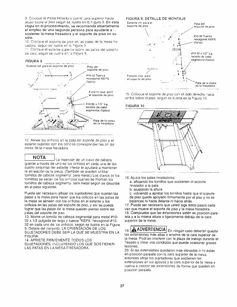
9 Coloque la mesa fresadora con la cara superior haciaabajo sobre el p_so segun se flustra en la Figura 9. En estaetapa en el procedimiento, se recomienda abiertamenteel empleo de una segunda persona para ayudarle asostener la mesa fresadora y el soporte de piso en susitio.
10. Coloque el soporte de p_so en las patas de la mesa fie-sadora, segun se flustra en la Figura 9.11. Coloque el estante superior sobre las patas del soportede ptso, seg0n se ilustra en :a Figura 9.
FIGURA 9
Estante inf. para el soporte de piso Pata del
i,_:.''": #10-32 Tuerca
,2" hexagonal KEPS,/
: ," /(hpic°)
4'
." I Estante sup. para
el soporte de piso
#10-32 x 1/2" Lg.tornillo de cabz.
segmental (tipico)
Pata de la mesade la fresadora
FIGURA 9, DETALLE DE MONTAJE
Estante inf. para el Pata del
soporte de piso - soporte de piso
, _ #10-32 Tuerea' ' _"" '_ hexagonal KEPS
(tipico)
_°
/Estante sup. para
el soporte de piso
#10-32 x 1/2" Lg._' tornillo de cabz.
j'
,_ segmental (tipico)
Pata de la mesade la fresadora
15. Coloque el soporte de piso con el lado derecho haciaarriba sobre el piso, segun se ilustra en la Figura 10.
FIGURA 10
12. Alinee los orificios en la pata del soporte de piso y elestante superior con los orificios correspondientes en laspatas de la mesa fresadora.
J La insercion de un clavo de cabeza/NOTA
grande a traves de uno de los orificios en cada una de lascuatro esquinas del estante inferior le ayudara, a mantenerla alineacion de la pieza. (Tambien se pueden utilizartornillos de cabeza segmental para metal.) Los clavos (o lostornillos) se sacan de los orificios cuando se montan lostornillos de cabeza segmental para metal segQn se describeen el paso siguiente.
Puede ser necesario aflojar los sujetadores que sujetan laspatas a la mesa para hacer que los orificios en las patas dela mesa se alineen con los orificios en el estante y losorificios en las patas del soporte de piso, y asi se puedaIograr que las patas de la mesa queden planas sobre lasparas del soporte de piso.13. Monte un tornillo de cabeza segmental para metal #10-32 x 1/2 pulgada de largo y tuerca "KEPS" hexagonal #10-32 en cada uno de los orificios, segQn se ilustra en la Figura9, Detalle det conjunto. LA ORIENTAClON DE LOSSUJETADORES DEBE SER LA QUE SE MUESTRA EN LAFIGURA.14. APRIETE FIRMEMENTE TODOS LOSSUJETADORES, INCLUYENDO LOS QUE SOSTIENENLAS PATAS EN LA MESA FRESADORA.
16. Ajuste los patas niveladoras:a. aflojando los tornillos que sostienen el soportenivelador a la patab. ajustando la alturac. volviendo a apretar los tornillos hasta que el soportede piso quede apoyado firmemente por el piso y no sebalancee ni hacia delante ni hacia atras.
17. Puede ser necesario que usted siga estos pasos cadavez que mueve el soporte de piso y la mesa fresadora.18. Compruebe que las extensiones esten en posici6n para-lela y a la misma altura o ligeramente debajo de la carasuperior de la mesa.
19. A/_ADVERTENClAj En ningun caso deberb,n quedar
las extensiones ma.s altas o encima de la cara superior dela mesa. Podrian interferir con la pieza de trabajo durante elfresado y crear una condicion que puede ocasionar graveslesiones.
20. Si las extensiones quedaron mas elevadas o no esta.nen posicion paralela con la cara superior de la mesa,entonces afloje los sujetadores que sostienen lasextensiones en los apoyos y la cara superior de la mesa yvuelva a colocar las extensiones de forma que queden enposicion paralela.
37

21.APRIETEFIRMEMENTETODOSLOSSUJETADORESOTRAVEZ.22.Paracerciorarsedequetodoestb,enorden,desliceunpedazopianodemaderaa Iolargodelacarasuperiordelamesaentodaslasdirecciones.Aseguresedequeelbordedelamaderasemuevalibrementesinentrarencontactoconlosbordesdelasextensiones.
BLOQUEDEEMPUJE1.Enrosqueelextremopequer_odelabarrasujetadorafirmementeenelorificioroscadoenlaplacasujetadorahastaquelabarrasalgahaciafueraconseguridadcontralaplaca,segOnseilustraenlaFigura11.2.Cercioresedequeelbloquedeempujeesteorientadodemodoquela"C"enlaplacasujetadoraquedehaciafuera,segunseilustraenlaFigura11.3.Montelaarandeladeseguridadconresortede1/4depulgadadeD.I.x 1/2pulgadadeD.E.x 3_64depulgadadeespesory latuercahexagonaldetornilloparametalde1/4-28aiabarrasujetadora,segunseilustraenlaFigura11.4.APRtETEfirmementelatuercaenlabarrasujetadora.5.Inserteelotroextremodelabarrasujetadoraatravesdelorificioenelbloquedeempuje.CercioresedequelaorientaciondelbloquedeempujesealaqueseilustraenlaFigura11.6.Montelaarandelade11/32D.I,x 11/16D,E.x 1/16depulgadadeespesory latuercademariposa5/16-18enlabarrasujetadorasegOnseilustraenlaFigura11.
FIGURA1111/32" D.I, x 11/16" D.E. x 1/16"
de espesor, arandela
Bloque de empuje
Placa sujetadora hacia eli fondo contra la superficie
', 1/4" I.D. x 112"
i x 3/64" de espesor,
arandela de seg.
con res. _
Barra sujetadora
"C" en la Placaetadora
5/16-18Tuerca de
mariposa
1/4-28 Tuerca para torn. hexagonal
7. No es necesario apretar la tuerca de mariposa. La barrasujetadora debe girar libremente en el bloque de empuje.
IA/ILLADVERTENClAj Ocasionaimente, las vibracionesproducidas por el funcionamiento de la fresadora puedenhacer que la tuerca del tornillo hexagonal para metal y laplaca sujetadora se aflojen en la barra sujetadora, REVISEPERIQDICAMENTE EST©S SUJETADORES Y TODOSLOS SUJETADORES para asegurarse de que esten bienapretados y seguros.
GUiA1. Monte ta guia ajustable para trabajos de junta en la guiade la mesa fresadora usando un tornillo prisionerohexagonal de 1/4-20 x 1 pulgada de largo, una arandela de9/32 D.I. x 3/4 D.E. x 1/16 de pulgada de espesor y laperilla sujetadora de la guia ajustable, como se muestra enlas Figuras 12a y 12b. La guia en forma de "V" en la guiaajustable para trabajos de junta se deslizara acoplandosecon la guia en forma de "V" en la guia de la mesafresadora.
2. Empuje la guia ajustable para trabajos de junta hastameterla en la guia de la mesa fresadora Io ma.s adentroposible y apriete la perilla sujetadora.
FIGURA 12a
mesa fresadora
Gul'a ajustable paratrabajos de junta
FIGURA 12b
1/4-20 x 1" Lg. tornillo
• . prisionero hexagonalGula ajustable para ,trabajos de junta
Gui'a de D.E. x 1116" de t_la mesa espesor, arandelafresadora
Perilla ajustable
sujetadora de la guia
3. Monte el sistema de orientaci6n de la gufa en la parteinferior de la guia usando los tornillos de cabezatroncoconica para metales #10-32 x 7/8 de pulgada delargo y las tuercas "KEPS" hexagonales #10-32, segQn seilustra en la Figura !3. (La parte de la tuerca de la tuerca"KEPS" entra en ia hendidura y la parte de la arandelaqueda fuera de la hendidura.) NO APRIETE los sujetadoresen este momento.
38

FIGURA13_td-32X77a"delargo,tornillo cabz. troncoconica
Guia dela mesa _ _
fresadora "_ "_ '_
, \
_ I 'Note la orientacion del surco
enet orientador de la gu_....._._ '_,
Superficie de orientador de la guia --'--"-- _ "\
debe estar al ras con la superficie pos- #10-32 Tuerca "_ Orientador
terior de la guia de la mesa fresadora hexagonal KEPS de la guia
FIGURA 14a
Perilla sujetadora 9/32" DJ. x 3/4" D.E. x 1/16"
de la gui'a de espesor, arandela
c
de la guiaCanal de lamesa fresadora
#10-32 x 7/8"
de largo,tornillo cabz.troncoc6nica
1/4-20 x 1-3/4" Lg. perno de cabezaredonda y cuello cuadrado
4. Para alinear la gufa, coloque en posicidn correcta la guiaen la mesa fresadora de modo que e! sistema deorientacion de la guia entre en los canales en la carasuperior de la mesa, como se muestra en la Figura 14a,5. Inserte un perno de cabeza redonda y cuello cuadradode 1/4-20 x 1-3/4 pulgadas de largo desde la cara inferiorde la mesa, a traves de la ranura en la guia, como semuestra en la Figura 14a.6. Coloque una arandela de 9/32 D.l. x 3/4 D.E. x 1/16 depulgada de espesor sobre el perno, como se muestra en laFigura 14a.7. Enrosque ligeramente una perilla sujetadora de la guiasobre el perno. NO APRIETE la perilla sujetadora en estaguia en este momento; la guia debe poder MOVERSELIBREMENTE desde la parte frontal hasta la parteposterior en la mesa.8. Repita los pasos del 5 al 7 para el otro lado de la guia.9. Cerciorese de que la guia ajustable para trabajos dejunta este Io mas adentro posible de la guia de la mesafresadora y que la perilla sujetadora se haya apretado conseguridad.10. Alinee la parte frontal de la guia con las marcas "0" enla cara superior de la mesa fresadora, como se muestra enla Figura 14b.11. APRIETE las perillas sujetadoras.de la guiaCERCIOR,_,NDOSE DE QUE LA GUIA NO SE MUEVE.12. APRIETE los dos tornillos de cabeza troncoconica #10-32 x 7/8 de pulgada de largo para asegurar et sistema deorientacion de la guia a la guia, como se muestra en la
Figura 14a.
FIGURA 14b
Marca "0"
//
//
/
• 1o ! z\ _' '. '/
13. Quite la guia de la mesa desenroscando las perillassujetadoras de la gu_a de los pernos de cabeza cuadrada ycuello redondo 1/4-20 x 1-3/4 pulgadas de largo mientrasque sostiene los pernos en su sitio desde la cara inferior deta mesa.
" 14. Quite las arandelas 9/32 D.I. x 3/4 D,E, x 1/16 depulgada de espesor de los pernos y seguidamente quitelos pernos.15. Guarde los sujetadores en un lugar conveniente paraque los pueda utilizar mas adelante.16. Monte el resguardo superior en la guia de la mesafresadora usando dos tuercas de empuje de 1/4 depulgada y e! pasador pivote de] resguardo superior 1/4 D.E.x 2-11/16 pulgadas de largo, segun se ilustra en laFigura 15:
a. Presione una de las tuercas de empuje hasta ponerlasobre un extremo del pasador pivote. (Sera necesariogolpear ligeramente la tuerca de empuje sobre elpasador pivote del resguardo superior con un martillomientras se apoya el otro extremo del pasador pivotedel resguardo superior.)b. Coloque en posici6n correcta el resguardo superioren la gufa de modo que los orificios en el resguardosuperior se alineen con agujero pasante en la gu[a de lamesa fresadora. CERCIORESE DE QUE LAORIENTACION DEL RESGUARDO SUPERIOR SEA LAQUE SE ILUSTRA EN LA FIGURA 15.c, Inserte el pasador pivote del resguardo superior atraves de los orificios de alineacion.d. Presione la segunda tuerca de empuje sobre el ottoextremo del pasador pivote del resguardo superior deigual forma como Io hizo en el paso "a".
FIGURA 15
1/4" Tuerca de Pasador pivote del
empuje con resguardo sup.arandela
Resguardo superior
1/4" Tuerca de empuje
39

e. Mueva el resguardo superior hacia arriba y haciaabajo unas cuantas veces para asegurarse de que semueve libremente.
rAI[, ADVERTENClAI Una vez que el resguardo superior
se haya montado a la guia, NO LO QUITE por ningunarazon. Su retiro puede dar lugar a una condicion defuncionamiento inseguro que puede ocasionar posibleslesiones corporates.
CON JUNTO DEL BLOQUE DE EMPUJE EN LA GUIA DELA MESA FRESADORA
1. Coloque en posici6n correcta la placa sujetadora enrelacion con el bloque de empuje, seg0n se ilustra en laFigura 16.2. Alinee el saliente y la parte en forma de V del bloque deempuje con el surco en la parte frontal de la guia y la parteen forma de V de la guia.3. Monte el bloque de empuje en la guia segun se ilustraen la Figura 16. El bloque de empuje debe moverselibremente a Io largo de toda la guia cuando el resguardoesta, en posici6n LEVANTADA.
FIGURA 16
La parte en forma />V del bloque de
empuje
\
Saliente
Placa
sujetad°ra_, i
BIoque de empuje
La parte en formaV de la gufa
Rebaje
NOTA
t. Es una buena pra,ctica quitar con frecuencia el polvo ylas astillas que se acumulan con el uso desde lassuperficies deslizantes de la guia y del bloque de empuje ydesde el surco en la guia.2. La aplicaci6n ocasional de una capa muy ligera de cerapara muebles alas SUPERFICIES DESLIZANTESsolamente del bloque de empuje mejorara, la acciondeslizante.
GUiA DE INGLETE
1. Monte la cabeza del transpodador en la barra de inglete.segun se ilustra en la Figura 17, usando un tornillo decabeza segmental para metal #10-32 x 1/'2 pulgada delargo.I I
I NOTA I Hay dos orificios redondos en la barrade inglete. Cerciorese de que el tornillo de cabezasegmental entre en el orificio correcto indicado
FIGURA 17
#10-32 x 1/2" Lg. tornillo
"q de cabz. segmental\
/ '
Barra de Use este
inglete
orificio
Cabeza de
transportador
2. Apriete el tornillo de cabeza segmental en la cabeza deltransportador de modo que la cabeza del tornillo apenastoque la barra de inglete pero todavia proporcione unaresistencia cuando se gira la cabeza del transportador.3. Monte la perilla, la arandela 3/16 D.t. x 9/16 D.E. x 0.040pulgada de espesor y el perno de cabeza redonda y cuellocuadrado #10-24 x 3/4 de pulgada a la barra de inglete y lacabeza del transportador, segQn se ilustra en la Figura 18.
FIGURA 18
Perilla_
3/16" D.I. x 9/16" x .040 L_;de espesor, arandela
Cabeza de ///// _
transportador_O//i_ _____7I _//_ i
Barra de inglete
#4-40 x 3/4" de
largo, tornillo cabz.
troncoconica
Puntero
de inglete
_. Tuerca
_'_i hexagonal
.-._ del numero
f,o(_ de cabeza redonda y
cuello cuadrado
4. Monte el puntero del inglete en la barra de ingleteusando el tornillo de cabeza troncoconica para metales#4-40 x 3/4 de pulgada de Fargo y la tuerca del tornillohexagonal para metales #4-40. Cerciorese de que elpuntero del inglete APUNTE en la direccion correcta.5. APRIETE FIRMEMENTE el tornillo y la tuerca.
40

FRESADORA EN LA MESA FRESADORA
[^I[LLADVERTENCIAjCerc,orese siempre de que la
fresadora NO ESTE CONECTADA a una toma de corriente
cuando se este instalando la fresadora en la mesa fresado-ra. S_ esta conectada. DESENCHUFE el cordon de
alimentaci6n electrica del er_chufe o el interruptor ydesenchufe el interruptor del enchufe
NOTA Aunque el conjunto de la guia se
muestra instalado en la mesa fresadcra en las figuras 19,20 y 21. se recomienda qu_tar el conjunto de la guia para
facititar la instalacion y el ret:ro de la fresadora. Para quitarel conjunto de la guia, consulte la los pasos del 13 at 15 enla pagina 39.
Fresadoras Craftsman con placas de base de tresorificios y 6 pulgadas de diametro1. Quite la placa de base de fa fresadora.
2. Guarde los tornillos y la ptaca de base en un lugarconveniente.
3. Mientras sostiene la fresadora al reves, coloquela enposicion correcta contra la cara inferior de la mesa
fresadora, segun se ilustra en la Figura 19. Haga girar tafresadora hasta que los tres orificios roscados en la basede la fresadora queden alineados con los tres orificios
embutidos correspondientes en la cara superior de la mesafresadora.
4. Cuando sea posible, alinee las manijas en la fresadoracon la mesa fresadora, segun se ilustra en la Figura 19.5. Inserte tres tornillos de cabeza embutida plana parame-tales #10-32 x 5/8 de pulgada de largo a traves de losorificios en la cara superior de la mesa y enrosquelos enlos orificios roscados en la base de la fresadora.6. APRIETE los tornillos FIRMEMENTE en la fresadora,
FIGURA 19
Fresadora Craftsman Modelo 9-27504
1. Quite ta placa de base de la fresadora.
2. Guarde los tornillos y la placa de base en un lugarconveniente.
3. Mientras sostiene la fresadora al reves, co!oquela enposicion correcta contra la cara inferior de la mesafresadora, segun se ilustra en la Figura 20.4. Haga girar la fresadora hasta que los cuatro orificiosroscados en la base de la fresadora queden alineados conlos cuatro orificios embutidos grandes correspondientesencima de la mesa fresadora. Los orificios se alinearan en
UNA SOLA posicion correcta unicamente.
5. Inserte cuatro tornil!os de cabeza embutida plana parametales de 1 pulgada de largo (M8 x 25 metricos) a travesde los orificios en la cara superior de la mesa yenrosque!os en los orificios roscados en la base de lafresadora. (Estos tornillos no vienen con la fresadora.)6. APRIETE FIRMEMENTE los tornillos en la fresadora.
FIGURA 20
Fresadoras Craftsman Modelos 9-27505, 9-27506,9-27510 y 9-275111. Quite la placa de base de la fresadora.2. Guarde los tornillos y la placa de base en un lugarconveniente.
3. Mientras sostiene la fresadora al reves, col6quela enposici6n correcta contra la cara inferior de la mesafresadora, segt_n se ilustra en la Figura 21 en la p#.ginasiguiente.4. Haga girar la fresadora hasta que los tres orificiosroscados en la base de la fresadora queden alineados conlos tres orificios embutidos grandes correspondientesencima de la mesa fresadora. Los orificios se alinearan enUNA SOLA posicion correcta Onicamente.5. Inserte cuatro tornillos de cabeza embutida plana parametales 5/16-18 x 1-1/4 de pulgada de largo a traves delos orificios en la cara superior de la mesa, como semuestra en la Figura 21 en la pagina siguiente yenrosquelos en los orificios roscados en la base de lafresadora. Estos tomillos son de color negro.6. APRIETE FIRMEMENTE los tornillos en la fresadora.
41

FIGURA21 ENTRAR EN CONTACTO con +a fresadora o ntnguna p,ezamovil de la fresadora.
• Cerciorese de que los cordones de alimentac_0n electnca
de la fresadora, de los accesenos, de la caja de! _nterruptory del cable de extens_0n NO INTERFIERAN NI PUEDANINTERFERIR con ninguna operac+0n de fresado o TOCARla pieza de trabajo.• El cordon de aIimentaci0n electrica de ta fresadora debeser conectado en la toma de corriente solamente
DESPUES que se ha terminado la configurac_on para su
eperaci0n de fresado.o Consulte la sigutente secc_on. OPERAClON de la CAJA
de! INTERRUPTER, en la pag_na 45.• Consulte la siguiente secci0n, use DE LA MESAFRESADORA, en la pagina .46.
Fresadoras de otras marcasSen& necesario que usted compre una placa adaptadoraprofesional para fresadoras Craftsman (9-25333), en suTienda Sears local o colocando el pedido mediante elcat,:ilogo Sears.Las fresadoras con una altura total de 13 pulgadas omenos y un diametro de base de 7 pulgadas o menospueden adaptarse con dicha placa profesiona!.
CORDON DE ALIMENTACION ELI_CTRICA ALINTERRUPTER
[_ADVERTENCIA 1° Cerciorese de que el cordon de alimentacion electrica deia caja del interrupter NO ESTE CONECTADO en una
toma de corriente mientras realice las tareas siguientes.Si esta conectado, DESCON#CTELO.o CERCIORESE DE QUE EL INTERRUPTER DE LA
FRESADORA ESTE EN LA POSICION DE APAGADO
(OFF).
1. Conecte et cord6n de alimentacion electrica de la
fresadora en uno de los enchufes en la caja del interrupter.2. Enrolle el cordon de alimentacion electrica sobrante.3. Envuelva los lades opuestos del rollo del cordon con dospedazos de cinta adhesiva o con un cordel resistente.4. Deje cierta holgura de mode que el cordon no se estirecuando se conecta en la caja del interrupter.5. Si 1odesea, en este memento enchufe el cordon dealimentacion electrica de un accesorio come. per ejemplo,una aspiradora para materiales secos y hOmedos o una luzen el otro enchufe.
,_ADVERTENCIA- NO CONECTE el cordd_n de alimentacion electrica de lafresadora en una toma de ¢orriente EN ESTE MEMENTO." SERA, NECESARIO utilizar un cable de extension debido
a Io corto del cordon en la caja del interrupter: Consulte lasiguiente seccion. REQUISITES ELECTRICOS. en elapartado use DEL INTERRUPTER dende hallara lasespecificaciones del cordon., Cerci0rese de que los cordones de alimentacion electricade la fresadora, de los accesor+os, de la caja del interruptery de! cable de extension NO TOQUEN Y NO PUEDAN
42

GUIA EN LAMESA FRESADORA
1 Consultelospasos 4 a8 , a F_gura 14aen la pag_na39
2. Aluste la guia er' el lugar ceseado para obtener ei corlerequerido.
i 13 Hay dos escalas con r_crementos _e 1_16 de pulgada.moldeadas en la cara su#er:c- de la mesa fresadora paraayudarleen elajuste de uga ,dela gu;a.4 APRIETE las periiras cuar_co el conlunto de la guia estealineado en el lugar deseadc
ASPIRADORA DE MATERIALES HUMEDOS Y SECOSEN LA GUIA
El conjunto de la guEa de ia _esa fresadora [iene un puertoen la parte posterior dor'de p._ede conectarse unamanguera de asp_radora de --ater_ales secos y humedosEl puerto permute la conex:cr' _e una boquilla de manguerade 2-1i2pulgadasde dJame:ro Para unirlaat puerto.empujela boquitladentrode Puerto m_entras sestiene laguLa en su sitio.
,_PRECAUCl0N El funcionamiento de la mesa
fresadora sin una aspiradora 2ara materiales secos yhumedos puede dar iugar a upa recoleccion excesiva o auna acumulacion de aserrin v astillas debajo del conjuntode la guia y del resguardo suoerior. Esto puede
obstaculizar el func_enamier':c de la mesa fresadora y delconjunto de la gu_a
RECOIVlENDACION: skn _mpc_ar s_ se esta o no se esta
utilizando una asp_radora para materiales secos yhumedos, quite las astillas y e_ aserrin ta madera debajodel conjunto de la guia y dei "esguardo superior segun seanecesario. AI quitar las astillas y el aserrin acumulado sepermite el buen funcionamien;o del conjunto de la guia ydel resguardo superior.RECOMENDACION: es siemare una buena practicamantener el area de traoajo _mpia. Segun seanecesario.quite las astillas y el aserrin ce la cara superior de ta mesafresadora, asi como cualquier cantidad de aserrin y astillasque se haya acumulado en ei piso alrededor de la mesafresadoratable.
,_ADVERTENCIA]AI hacer Io indicado arriba, tenga en cuenta Io siguiente:
o La FRESADORA y EL INTERRUPTOR deben estarapagados.• La broca fresadora NO debe estar girando.° El cordon de alimentacion electrica de la fresadora
debe estar DESCONECTADO del interruptor.• El cordon de alimentacion electrica del interruptor debeestar desconectado del cable de extension.
INSERTOS DE LA CARA SUPERIOR A LA MESA
FRESADORAEsta mesa fresadora viene con tres insertos de la cara
superior de la mesa en los siguientes tama_os de orificio:o 1-1/4 pulgadas de diametro, para usarlos con brocasfresadoras de diametros de hasta 1-1/8 pulgadas- 1-7/8 pulgadas de diametro, para usarlos con brocasfresadoras de diametros de hasta 1-3/4 pulgadas• 2-1/8 pulgadas de d_ametro, para usarlos con brocasfresadoras de diametros de hasta 2 pulgadas
• Para las brocas fresadoras con d_ametros entre 2 y2-3,4 pulgadas no se utdizan los _nsertos de la carasuperior de la mesa. Vease ia Figura 22
FIGURA 22
,_ADVERTENCIA Una broca fresadora de 2-3/4
pulgadas de diametro es la broca fresadora MASGRANDE que se puede utilizar CON SEGURIDAD en estamesa fresadora.
1. Seleccione el inserto de la cara superior de la mesa quemejor se adapte a la broca fresadora que se utilizara_.2. Monte el inserto en la cara superior de la mesapresiona.ndolo en et orificio grande en la cara superior de lamesa fresadora, segun se ilustra en la Figura 23.3. Presione abajo con igual presion sobre las lengOetas enel inserto de modo que las lengOetas encajen a presion ensu sitio.
4. Para quitar el inserto, meta un dedo en el orificio delinserto y tire suavemente hacia arriba hasta que las
lengOetas se salgan del orificio. Cuando no se le estenusando, guarde los insertos en un lugar conveniente,
,_ADVERTENClA NO TRATE DE quitar el inserto de
la cara superior de la mesa a menos que se haya quitadola broca de la fresadora.
FIGURA 23
43

ASPECTOS GENERALES
El interruptor electrico esta. diser_ado para utilizarse con lamayoria de las mesas fresadoras y fresadoras Craftsman.Brinda la comodidad de tener un interruptor deencendido-apagado en la parte frontal de la mesa.
eliminando asi la necesidad de extender la mano pordebajo de la mesa para apagar y encender la fresadora.
1NOTAI La fresadora electronica (9-27510) es
un caso especial que se explica en la seccionOPERACION DE LA CAJA DE INTERRUPTORES Y LAFRESADORA.
El interruptor electrico tambien proporciona un control deencendido-apagado simultb, neo opcional de un accesorio
adicional como, por ejemplo, una luz, una aspiradora, etc.El interruptor incorpora un interruptor reajustable interno decircuito, para proporcionar la proteccion en situaciones de
sobrecarga.
REQUERIMIENTOS ELECTRICOS
En caso de un real funcionamiento o una averia, la puestaa tierra de la fresadora proporciona la trayectoria de menosresistencia para la corriente electrica reduciendo asi elriesgo de descargas electricas para el usuario, Esta cajade interruptores est#, equipada con un cordon dealimentacion electrica que tiene un conductor de puesta atierra y un enchufe con puesta a tierra. El enchufe debeconectarse en un enchufe correspondiente que esteinstalado y puesto a tierra correctamente de acuerdo contodos los codigos y ordenanzas locales.
NO MODIFIQUE el enchufe provisto si este no entra en latoma de corriente. Haga que un electricista cualificadoinstale et enchufe apropiado.
La conexion incorrecta del conductor de puesta a tierrapuede producir riesgos de descarga electrica. El conductorcon el aislamiento que tiene una superficie externa verde,con o sin rayas amarillas, es el conductor de puesta atierra. Si es necesario reparar o reemplazar el cordon o elenchufe electrico, NO CONECTE el conductor de puesta atierra con un terminal con corriente.
Consulte a un electricista o a una persona cualificada deservicio si no entiende totalmente las instrucciones depuesta a tierra o si tiene alguna duda de si la caja deinterruptores esta. puesta a tierra correctamente.
Utilice solamente cables de extension de calibre 14, o uncalibre mayor, de tres conductores que tengan tres puntasy tomas de corriente de tres orificios que acepten elenchufe de la herramienta.
Repare o substituya inmediatamente un cordon dar_ado odesgastado.
La toma de corriente en la parte posterior de la caia deinterruptores de la fresadora aceptara un enchufe de dos
puntas de una fresadora o un accesorio con DOBLEAISLAMIENTO o un eachufe de tres puntas con puesta atierra.
Este interruptor esta diseRado para el uso en un circuito
que tenga una toma de corriente, segun se ilustra en lafigura A. La caja de tnterruptores tiene un enchufe conpuesta a tierra, segun se itustra en la figura A.
Si no se dispone de un enchufe correctamente puesto atierra, se puede utifizar un adaptador temporal, segun seitustra en la figura B. para conectar este enchufe con unatoma de dos orificios, como se muestra en la figura C.
FIGURA A FIGURA B FIGURA C
CL_bierta de la
caja con pues-ta a tierra
_Espiga de
puesta a tierra
Adaptador
Medio de pues-ta a tierra
Cubierta de la
caja con pues-ta a Nerra
El adaptador temporal debe ser utilizado solamente hastaque un enchufe correctamente puesto a tierra pueda serinstalado por un electricista cualificado. El tal6n o la orejetarfgida de color verde que sale del adaptador se debeconectar con una tierra permanente como, por ejemplo,una caja de enchufe correctamente puesta a tierra.
,_ADVERTENClA NO PERMITA QUE LOS DEDOS
TOQUEN LOS TERMINALES DEL ENCHUFE ALINSTALAR O QUITAR EL ENCHUFE. SI ESTAHERRAMIENTA ELECTRICA NO EST, _,
CORRECTAMENTE PUESTA A TIERRA, PUEDENCREARSE POSIBLES PELIGROS DE DESCARGAS
ELC:CTRICAS, QUE PUEDEN CAUSAR INCLUSOMUERTES, PARTICULARMENTE CUANDO SE UTILIZAEN UN LUGAR HOMEDO, CERCA DE INSTALACIONESDE PLOMER[A O ALAIRE LIBRE. SI OCURRE UNDESCARGA EL#:CTRICA, HAY SIEMPRE LA
POSIBILIDAD DE PELIGROS SECUNDARIOS COMO,POR EJEMPLO, QUE SUS MANOS ENTREN ENCONTACTO CON LA BROCA FRESADORA.
,_ADVERTENClAJ UTtLICE LA CAJA DE
m
INTERRUPTORES SOLAMENTE SI ESTA EST, _,MONTADA CORRECTAMENTE EN LA MESAFRESADORA. UTILfCELA SOLAMENTE CON UNAFRESADORA QUE TAMBtEN ESTE INSTALADACORRECTAMENTE EN UNA MESA FRESADORA
ARMADA SEGUN LAS INSTRUCCIONES.
44
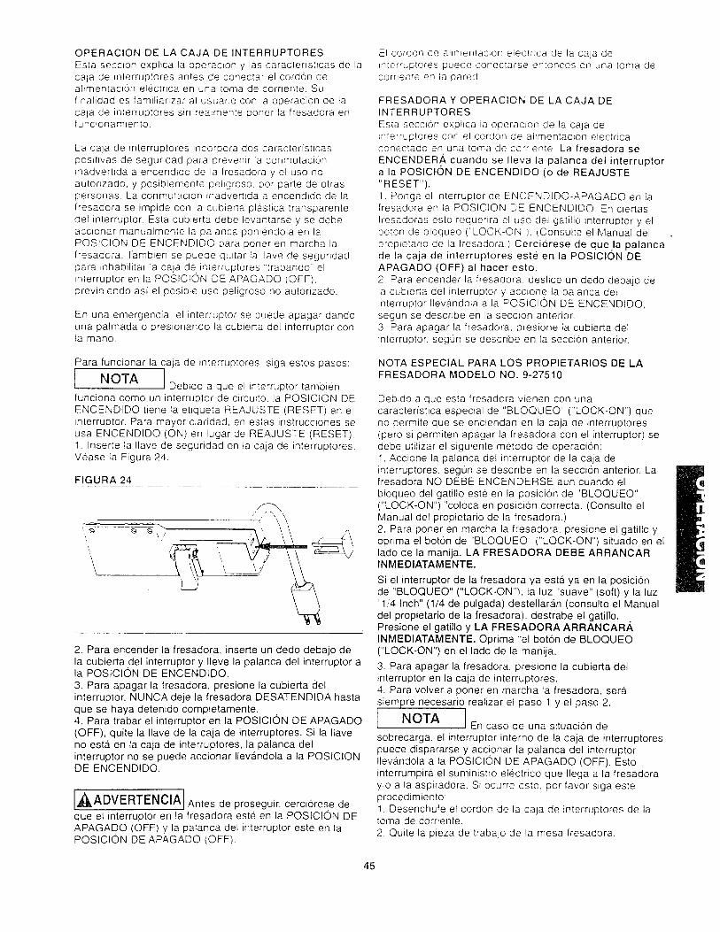
OPERACIONDELACAJADEINTERRUPTORESEstasecc_onexphcataoperac_onylascaractenst_casdelacajadernterruptoresantesdeconectarelcordondeahmentac_0nelectrlcaenunatomadecornente.SufinatidadesfamiliarizaralusuarioconlaoperaciondelacaladeinlerruptoressinreaLmenteponertafresadoraenfunc_onamtento.
Lacaiadeinterruptores_ncorporadoscaracterishcaspos_twasdesegundadparaoreven_rlaconmutac_onEnadvertidaaencendidodetafresadoray elusonoautorizado,y posiblementepehgroso,porparledeotraspersonas.Laconmutact0n_r'advertidaaencendidodelafresadoraseimpideconlacubiertaplasticatransparentedelinterruptor.EstacubiertadebetevantarseysedebeaccionarmanuaJmentelapalancapon_endolaenlaPOSICIONDEENCENDIDOparaponerenmarchalafresadora.TambiensepuedequitarlaI!avedeseguridadpara_nhabilitarlacajadein_erruptores'trabando"elinterruptorenlaPOSICIONDEAPAGADO(OFF),previniendoasielposibteusopeligrosonoautorizado.
Enunaemergencia,elinterruptorsepuedeapagardandounapalmadaopresionandotacubiertadelinterruptorconlamano.
Para funcionar la caja de interruptores, siga estos pasos:
I Debido a que el interruptor tambienNOTA
funciona como un interruptor de circu_to, la POSICION DE
ENCENDIDO tiene la etiqueta REAJUSTE (RESET) en elinterruptor. Para mayor claridad, en estas instrucciones seusa ENCENDIDO (ON) en lugar de REAJUSTE (RESET).1. Inserte la Ilave de seguridad en la caja de interruptores.Vease la Figura 24.
FIGURA 24
• <:j
\
'_J,\i,
2. Para encender la fresadora, inserte un dedo debajo dela cubierta del interruptor y IIeve la palanca del interruptor ala POSlCION DE ENCENDIDO.
3. Para apagar la fresadora, presione la cubierta delinterruptor. NUNCA deje la fresadora DESATENDIDA hastaque se haya detenido completamente.4. Para trabar el interruptor en la POSlClON DE APAGADO(OFF). quite la Ilave de la caja de interruptores. Si la Ilaveno esta. en la caja de interruptores, la palanca delinterruptor no se puede accionar Ileva.ndola a la POSICI©NDE ENCENDIDO.
^ I,_ADVERTENClAj Antes de proseguir, cerciorese deque el interruptor en la fresadora este en la POSICION DEAPAGADO (OFF) y la palanca del interruptor este en laPOSICION DE APAGADO iOFF).
El cordon de ahr,nentac_on electr_ca de la caja de_n[erruptores puede conectarse en[onces en una [oma decornenle en ia pared
FRESADORAY OPERACION DE LACAJADEINTERRUPTORES
Esta secc_0n exphca la operacEon de la caja deEnterruptores con el cordon de alrmentac_on electr]caconectado en unatoma deccrnente La fresadora se
ENCENDER,,&, cuando se Ileva la palanca del interruptora la POSlCl0N DE ENCENDIDQ (o de REAJUSTE
"RESET").!. Ponga el _nterruptor de ENCENDIDO-APAGADO en lafresadora en la POSICION DE ENCENDIDO. En c_ertas
fresadoras esto requerira el uso det gatillo interruptor y elboron de bloqueo ("LOCK-ON). (Consutte el Manual del
prop_etario de la fresadora,) Cerciorese de que la palancade la caja de interruptores este en la PQSlClON DE
APAGADO (OFF) al hacer esto.2. Para encender la fresadora, deslice un dedo debajo dela cubierta del interruptor y acc_one la palanca del_nterruptor Ileva, ndola a la POSICION DE ENCENDIDO,segun se describe en la secc_on anterior.
3. Para apagar la fresadora, presione la cubierta delinterruptor, segun se describe en ta seccion anterior,
NOTA ESPECIAL PARA LOS PROPIETARIOS DE LAFRESADORA MODELO NO. 9-27510
Debido a que esta fresadora vienen con una
caracteristica especial de "BLOQUEO" ("LOCK-ON") queno permite que se enciendan en la caja de interruptores(pero si permiten apagar la fresadora con el interruptor) sedebe utilizar el siguiente metodo de operacion:1, Accione la palanca del interruptor de la caja deinterruptores, segun se descnbe en la seccion anterior. Lafresadora NO DEBE ENCENDERSE aun cuando el
bloqueo del gatillo este en la posicion de 'BLOQUEO"("LOCK-ON") "coloca en posicion correcta. (Consulte elManual del propietario de la fresadora.)2. Para poner en marcha la fresadora, presione el gatillo yoprima et boton de "BLOQUEO" ("LOCK-ON") situado en ellado de la manija. LA FRESADORA DEBE ARRANCARINMEDIATAMENTE.
Si el interruptor de la fresadora ya esta ya en la posicion
de "BLOQUEO" ("LOCK-ON%, la luz "suave" (soft) y la luz"1/4 Inch" (1/4 de pulgada) destellara, n (consulte el Manual
del propietario de la fresadora), destrabe el gatillo.Presione el gatillo y LA FRESADORA ARRANOAR.&INMEDIATAMENTE. Optima "el boton de BLOQUEO
("LOCK-ON") en el lado de la manija.
3. Para apagar la fresadora, presione la cubierta delinterruptor en la caja de interruptores.4. Para volver a poner en marcha la fresadora, serasiempre necesario realizar el paso 1 y el paso 2.
INOTA
I En caso de una situacion de
sobrecarga, el interruptor interno de la caja de interruptores
puede dispararse y accionar ta palanca del interruptorIlevandola a la POSICION DE APAGADO (OFF). Esto
interrumpira el suministro electrico que Ilega a la fresadorayo a la aspiradora. Si ocurre esto. por favor siga esteprocedimiento:
1. Desenchufe el cordon de la caja de interruptores de latoma de corriente.
2. Quite la pieza de trabaio de la mesa fresadora.
45

3. Corrija la causa de la situacion de sobrecarga (es decir,quite el exceso de material de trabajo o reduzca lavelocidad de avance del material).
4. Conecte el cordon de alimentacion electrica de la cajade interruptores en la toma de corriente.5. Vuelva a poner en marcha la fresadora segun se
.describe en la seccion QPERACl0N DE LA FRESADORA
Y LA CAJA DE INTERRUPTORES en la pagina 45.
,_ADVERTENCIA Para su propia SEGURIOAD y la
SEGURIDAD DE OTRAS PERSONAS, siga esteprocedimiento cuando no se este usando la mesafresadora:
1. Accione la patanca del interruptor Ilev&.ndola a laPOSICION DE APAGADO (OFF) y quite la llave.2. Apague la fresadora.3. Desenchufe el cordon de alimentacion electrica de la
caja de interruptores de la toma de corriente.4. Quite la broca fresadora de la fresadora.
5. Cerciorese de que el conjunto de la boquilla de lafresadora este debajo de la cara superior de la mesafresadora.
6. Guarde la Ilave de la caja de interruptores en un lugarseguro fuera del alcance de los niSos u otras personas noautorizadas.
A],_ADVERTENClA 1En caso de un apagon, un fusible
quemado, o el "atascamiento" de la fresadora mientras serealiza el trabajo de fresado, presione la cubierta delinterruptor para accionar la palanca del interruptorIlevandola a la POSICION DE APAGADO (OFF) y quite laIlave de la caja de interruptores hasta que se hayacorregido la fuente del probiema. Ademas. desconecte lacaja de interruptores de la toma de corriente.
USO DE LA MESA FRESADORAr f
[,_ADVERTENClA l ANTES DE cada uso, cerciorese de
que el soporte de piso este bien ESTABLE en el piso y NOse balancee ni hacia delante ni hacia atr,-Ss.Si nota atgunbatanceo, nivele el soporte de piso segQn se describe enuna secci6n anterior.
La guia ajustable en su mesa sirve como una guia contrala cual se debe sostener la pieza de trabajo para Iograr laexactitud en el trabajo de fresado. FRESAR A MANOALZADA (sin sostener la pieza de trabajo contra la guia) espeligroso y SE DEBE EVlTAR TERMINANTEMENTE si nose est,_ trabajando con brocas fresadoras tipo piloto.
AJUSTE DE LA PROFUNDIDAD Y LA ALTURA DECORTE
IDESENCHUFE la fresadora para estos ajustes. Haga girarel resguardo superior hacia arriba para tener accesocompleto a la broca fresadora y realizar los ajustes.Seleccione una tabla lisa con bordes bien parejos y rectosOtras recomendaciones son las sigu_entes:1. Marque las tineas "A"y "B "en el extremo de estetablero. La linea "A" indica la profundidad deseada del
corte (la cantidad de material que usted desea quitar) y lalinea "B" indioa la altura deseada de code. Vea la Figura25.
2. Coloque esta tabla contra la cara de la guia de la mesafresadora con el borde descansando sobre la cara superior
de la mesa y el extremo marcado con las lineas "A" y "B"cerca de la broca. Vea la Figura 25. (Antes de realizar losajustes, cerciorese de que la fresadora esteDESCONECTADA.)
3. Afloje ambas perillas grandes para permitir elmovimiento de la guia y para moverse hacia delante yhacia atras hasta que el filo mas externo de la brocafresadora se alinee con la linea " A". Apriete ambasperillas.
4. Levante o baje la fresadora hasta que la parte superiordel filo de la broca se alinee con la linea "B". (Consulte suManual de propietario de la fresadora donde hallarb,instrucciones para ajustar su fresadora correctamente,)Despues de hacer este ajuste, asegurese de que lafresadora ESTE FIRMEMENTE APRETADA en la base dela fresadora, la broca ESTE FIRMEMENTE APRETADA en
el portabrocas de la fresadora y la base de la fresadoraESTE FIRMEMENTE SUJETA a la cara superior de lamesa fresadora.
5. Quite la tabla de la g.uia y baje el resguardo superiorIleva, ndoto a la POSICION DE OPERACION.
[,_ADVERTENClA I No ponga a funcionar la fresadora
si cualquier parte de la broca entra en contacto con elresguardo superior.
INOTAI Usted debe utilizar una tabla de
desecho en lugar de la pieza de trabajo real mientras haceestos ajustes.
FIGURA 25
Ll'nea "A" Linea "B"
46

TRABAJOS DE FRESADO USANDO LA GUIASIN
BLOQUE DE EMPUJE
Corte completo de bordea:Para ;ograr la maxima fuerza y preo, s_on, ias '.aoias que seensamblaranjuntasdeben seriisas y rectas Los bordesdebe'- ser rectos respecto a la superfloe de 'a p_eza detrabao Usted puede rechf:carlos bordes e _ su mesafresaaora usando una broea rectificadora,
t Compruebe para ver si !a cara de ia guia ajustable para
trabaios de junta esta at ras con ta eara de :a guia de lamesa fresadora. S_ no es as_. afioje la perilia suietadora dela gu;a ajustable en la guia para trabajos de junta yajustela. Apriete la periFa s_letadora de la guia en la gu_a
ajusta_te
JNOTAJ La gula ajustabie sara t'abalos de junta
propcrciona un soporte cor_t_nuo para la p_eza de trabalocuando se la hace avanzar mas alia de la broca fresadora.
La gu_a ajustable para trabajos de junta compensa para elmargen libre que queda despues de pasar et material porla broca fresadora.
2. Ajuste la profundidad y la altura dei corte (el material queusted desea quitar) de la broca fresadora segun sedescribe en los pasos 1 - ".4..en la secci0n "AJUSTE DE LAPROFUNDIDAD Y LA ALTURA DEL CQRTE" en la pa.gina
46. Asegure firmemente la guia y la fresadora segun sedescribio anteriormente. (Antes de intentar reatizar
cualquier aluste, cerci6rese de que la fresadora estedesconectada.)3. BAJE EL RESGUARDO SUPERIOR poniendolo en laposlcion correcta de operacion. (Para mayor claridad, el
resguardo superior se muestra levantado.)4. Compruebe sus ajustes encendiendo la fresadora,usando el interruptor, y haciendo avanzar un pedazo de
madera de desecho algunas pulgadas ma.s all,a de la brocafresadora. Entonces detenga y apague la fresadora usando
el interruptor.
Haga avanzar la pieza de trabajo contraNOTA
la rotacion del borde cortante (en la direcci0n indicada porla flecha en la Figura 26).
FIGURA 26 -
5 Atlole la cerdla suletadora de ',a gu,a en ia guia ajustabiepara tra_ajos de jur'la y muevala haoa fuera, pon_endola aras cor':ra e! horde acabado de la madera de desecho
Vueb,,a a apretarla penlla Vea !a Figura266 Res_ta e! corte de prueba en la madera de desecho eor_
el resguardo suoenor ABAJO7' La mesa fresadora eslara hsta para su uso en esemome_[o
1NOTAJ Para obtener los mejores resultados er"
los tra_alos de lunta, haga cortes muy superficiales, de1 32 de pulgada o menos.
Corte de bordes con brocas fresadoras sin piloto:1 Coioque en posic_on correcta la guia ajustable paratrabajcs de junta de modo que su cara quede al ras con la
cara de la gu_a de ta mesa. Apriete la perilla sujetadora dela gu_a alustable en la guia para juntar. Vea la Figura 27.2. A/uste la profundidad y la altura de', corte (es decir, elmatenal que usted desea quitar) de la broca fresadora,seg0n se describio previamente en el AJUSTE DE LA
• PROFUNDIDAD Y LA ALTURA DEL CORTE, pasos 1 - 4en la pag_na 46. Apriete ambas perillas sujetadoras de la
gufa para trabar la guia en la mesa. Asegure firmemente lafresadora. (Antes de intentar realizar cualquier ajuste,
cerci0rese de que la fresadora este DESCONECTADA).3. BAJE EL RESGUARDO SUPERIOR poniendolo en la
posicion correcta de operaci6n. Para mayor claridad, elresguardo superior se muestra levantado.4. Haga un corte de prueba con un pedazo de madera dedesecho para cerciorarse de que los ajustes sonsatisfactorios.
Haga avanzar el trabajo CONTRA laNOTA
rotacion del borde cortante (en la direccion indicada por la
flecha en la Figura 27).5. La mesa fresadora estara, lista para su uso en esemomento.
FIGURA 27
Para mayor claridad, el resguardo superior se muestra levantado
Para mayor claridad, el resguardo superior se muestra levantado
47

Corte de bordes con brocas fresadoras con piloto:1. Coloque en posic_6n correcta la guia de Jgual formacomo Io hizo con las brocas sin piloto.2. Mueva hacia arras la guia solamente Io justo parapermitir que el piloto controle la profundidad de! code.Co!ocar la gu_a Io m#,s cerca posible del piloto servira
como respaldo y ayudara a prevenir las probabilidades deque ocurra un accidente y posibles dar_os corporales. Veala Figura 28.3. BAJE EL RESGUARDO SUPERIOR poniendolo en laPOSICION CORRECTA DE OPERACION. Para mayorclaridad, el resguardo supenor se muestra tevantado.4. Haga un corte de prueba con un pedazo de madera dedesecho para cerciorarse de que los ajustes sonsatisfactorios.
J Haga avanzar el trabajo CONTRA la/NOTA
rotacion del borde cortante (en la direccion indicada por laflecha en la Figura 28).5. La mesa fresadora estara lista para su uso en esemomento.
FIGURA 28
FIGURA 29, VISTA DESDE LA IZQUIERDA DE LA FRESADORA
Localizaci0n Parle frontal de la gu_adel corte /
Resguardo Broca fresadora
Pieza de trabajo
Parte sup. de lafresadora
/ Fresadora
Profundidad
del corte
NOTA Haga un corte de prueba con un
pedazo de madera de desecho antes de hacer su codefinal. Haga avanzar ta pieza de trabajo en la direcci0n de lafiecha. (Consutte la Figura 30.)
FIGURA 30
\\\\
Para mayor claridad, el resguardo superiorse muestra levantado
TRABAJOS DE SURCOS, ACANALADURAS Y VETASDESCONECTE siempre la fresadora antes de efectuarcualquier graduaci6n o ajuste o antes de cambiar la broca.
AI fresar, HAGA SIEMPRE AVANZAR la pieza de trabajocontra la rotacion del borde cortante. Haga avanzar lapieza de trabajo en la direccion de la flecha, como en laFigura 28.
Para Iograr la maxima precision, un borde de su pieza detrabajo (el borde que se desliza situa.ndolo contra la guia)debe estar pedectamente alineado y recto. Configure suguia de la siguiente manera:1. Coloque en posicion correcta la guia detras de la brocafresadora para la profundidad deseada de corte (ladistancia del corte desde el borde de la pieza de trabajo,segt]n se ilustra en la Figura 29). Cerciorese de que elresguardo superior este en su sitio segun se muestra en lafigura.2. APRIETE firmemente ambas perillas.3. Haga el corte deslizando el borde recto de la pieza detrabajo contra la guia, segun se ilustra en la Figura 30.(Para cada corte sucesivo, seria necesario reajustar laguia.)
f JAI fresar cortes profundos (controlados]NOTA
por la broca fresadora) en una pieza de trabajo, quite unapequet_a cantidad de material para impedir la sobrecargade su fresadora. Repita la operacion con varios pases quese hacen cada vez ma,s profundos hasta Iograr laprofundidad deseada.
CORTE DE EXTREMOS USANDO LA GUiA CON ELBLOQUE DE EMPUJE
El
[,_ADVERTENClAJ El corte de extremos se realiza conel resguardo superior volteado hacia atra.s de modo que nocubra la broca. Por io tanto, debe ACTUAR CON SUMACAUTELA cuando corte extremos para proteger sus dedos,manos o cualquier otra parte de su cuerpo. NO TOQUE LABROCA, puesto que podrian ocurrir graves lesionescorporales.
AI fresar los extremos de la pieza de trabajo para hacerespigas, juntas deslizantes de cola de milano y juntasmachihembradas, la pieza de trabajo debe estar lisa conlos bordes y los extremos rectilineos entre siy lassuperficies. Todas las superficies deben ser rectas o estaren un angulo de 90" entre si.
48

INOTAI El bloque de empuje y ei conjunto de Ia
placa sujetadora no daran buenos resultados con p_ezasde trabajo que tengan mas de 4 pulgadas de ancho
Corte de espigas1. Asegurese de que la gu_a alustable para trabajos dejunta este trabada en pos_c',on con su cara al ras contra lacara de la guia de la mesa fresadora
2. Monte el conlunto del bloque de empuje en la guia de lamesa fresadora, segun se ilustra en la Figura 16 (en lapagma 40) en la secci6n CON JUNTO DEL BLOQUE DEEMPUJE A LA GUfA DE LA MESA FRESADORA.
3. Instale el inserto apropiado de la cara superior de lamesa en el orificio de la cara superior de la mesa.4. Marque ]as lineas "A" y 'B en et borde de la pieza detrabajo m#,s cercano al extremo que desea cortar. La linea'A"es para la PROFUNDIDAD COMPLETA DE CORTE (la
cantidad total de material que usted desea qurtar) y la linea"B" es para la ALTURA DESEADA COMPLETA DE LA
ESPIGA. Vea la Figura 31.5. Coloque en posici6n correcta la pieza de trabajo entre laplaca sujetadora y et b!oque de empuje, de modo que su
lado quede al ras contra la cara de la guia. e! extremo quedesea cortar quede descansando sobre el borde del orificio
del inserto de la cara supenor de la mesa fresadora y elborde marcado con las Lineas "A" y 'B" quede hacia labroca fresadora. Sujete firmemente la pieza de trabajo enesta posici6n apretando firmemente la tuerca de mariposasobre la barra sujetadora, m_entras se asegura de que laplaca sujetadora quede odentada hacia la pieza de trabajo.como se muestra en la Figura 31. Cerci6rese de que la
fresadora este DESCONECTADA cuando vaya a colocaren posici6n y sujetar la pieza de trabajo y realizar ajustes.
FIGURA 31
Parle lateral de la
pieza de trabajodebe dar su cara alras eontra contra la
cara de la gu_a
Filo superiorde le brocafresadora
Pieza de trabajo Tuerca de
Placa mariposa
sujetadora
Guia
:lue de
empuje
Borde exterior
fresadora
Inserto de la cara
superior de la mesa
Borde del orificio del inserto
en la cara superior de la tabla
t
Linea "A"
4 pulgadas m;_ximode ancho
t I Apriete la tuerca de mariposa justo IoINOTA
suficiente para sujetar firmemente la pieza de trabajo en laposicion correcta. APRETAR EXCESIVAMENTE la tuercade mariposa podria eausar agarrotamiento en elmovimiento deslizante del bloque de empuje. Io que a suvez puede causar variaciones y/o peldaSos en la superficiede la espiga acabada al cortarla. Vea la Figura 35 en la
pa.gina 50.6. Deslice ta pieza de trabajo cerca de la broca y ajuste laguia y la fresadora, segun se describio anteriormente, demodo que el borde mas hacia fuera de la broca quedealineada con la linea 'A" y el filo superior de la broca estealineado con la hnea "B"."Vea la Figura 31.
Apne[e f_rmemente ia guia y Pa fresadora, segun sedescribe0 an[er_ormen[e en la secoon AJUSTE DE LAPROFUNDIDAD Y DE LA ALTURA DEL CQRTE en la
pagma 467. Deshce e! bloque de empuje y. por Io tanto, la p_eza detrabajo, de regreso a su pos_ci6n anterior, segun se ilustraen la Figura 32
AI fresar. HAGA SIEMPRE AVANZAR la pieza de trabajoCONTRA la ro[ac_0n del borde codante. Haga avanzar lap_eza de [rabajo en la dJrecc_on indicada pot la flecha en laFigura 32.
8. Encienda la fresadora, usando el interruptor. Mientras
sostiene el bloque de empuje y dirige la pieza de trabajocontra fa guia con AMBAS MANOS Y TODOS LOS
DEDOS a una distancia prudencial de la broca que gira,haga avanzar la pieza de trabajo a traves de la broca parahacer UN CORTE DE PROFUNDIDAD COMPLETA EN UN
SOLO PASE, segun se ilustra en la Figura 32. (NO DEJE
de hacer avanzar la pieza de trabajo hasta que HAYAPASADO TOTALMENTE por la broca.)
I I Sujete firmemente y haga un corte deINOTA
prueba con un pedazo de madera de desecho paracomprobar sus ajustes antes de hacer su corte acabado.9. APAGUE la fresadora, usando el interruptor. Destrabe lapieza de trabajo y deslice el bloque de empuje de regresoal otro lado de la broca.
10. Coloque en posici6n correcta y sujete firmemente ellado opuesto de la pieza de trabajo de igual manera segQnse describe en el paso 5. (Cerci6rese de que la tuerca demariposa esta apretada justo Io suficiente para sujetarfirmemente la pieza de trabajo y el extremo que va a cortareste descansando sobre ta cara superior de la mesa
fresadora,l Repita los pasos 7, 8 y 9. (Consulte la Figura33 en la pagina 50.)11. Para cortar los extremos de la espiga, coloque en
posici6n correcta y sujete firmemente la pieza de trabajo deigual forma como Io hizo en el paso 5 indicado arriba, con
la diferencia de que el borde de la pieza de trabajo debesostenerse a ras contra la cara de la guia y el extremo quese cortara debe reposar sobre la cara superior de la mesafresadora, Vea la Figura 34 en la pagina 50. Repita lospasos 7. 8, 9 y 10.
49

IAIcortarlasespigas,sujeteslempreINOTA
firmemente la pieza de trabajo con el extremo que deseacortar reposando sobre la cara superior de ta mesafresadora. Esto reducira al minimo las marcas tipo peldaho
en la superficie acabada de la espiga debidas a Iasvariaciones en la parte plana de la cara superior de lamesa. (Consulte la Figura 35.)
INOTA I CORTE SIEMPRE LA PROFUNDIDAD
COMPLETA en los cuatro lados de la espiga en un solopase a traves de la broca.
FIGURA 33
FIGURA 34
/\-
TRABAJO DE FRESADOAMANOALZADA USANDOLA GUiA Y EL BLOQUE DE EMPUJE
Con brocas fresadoras tipo piloto:Sin el pasador de arranque:
[,_ADVERTENCIA Fresar sTn el conjunto de la guia
un=taria y et resguardo supenor podria causar accidentes yposibles les_ones corporates. Se debe actuar conEXTREMA CAUTELA en esta operacl0n de fresado
DESCONECTE siempre la fresadora antes de efectuar
cualquier graduacion o ajuste o antes de cambiar la broca.
Haga avanzar siempre la pieza de trabajo contra larotacion del borde cortante
Solamente deben utilizarse las brocas fresadoras tipopiloto.
Muchas aplicaciones de fresado (como se muestra en lasfiguras 36 y 37) requeriran quitar la guia de la mesa,
La Figura 36 es un ejemplo del FRESADO EXTERNO.o La posicion correcta de la pieza de trabajo en la mesafresadora en relacion con la broca fresadora debe ser laque se muestra en la figura.• La direccion de avance de la pieza de trabajo a traves dela broca fresadora debe ser segun se indica en la figuracon la fiecha de la direccion y CONTRA la rotacion de labroca fresadora.
FIGURA 36
FIGURA 35
Escalones en
la superficie
de la espiga
50

LaFigura37esunejemptodelFRESADOINTERNQ• La pos_c_0n correcta de la pieza de trabajo en la mesatresadora en relac_0n con la broca fresadora debe set la
que se muestra en la figura• La d_recc_6n de avance de la p_eza de trabalo a traves dela broca fresadora debe ser segun se _ndica en la hguracon la flecha de la direcc_0n '/ CONTRA ta rotacr0n de labroca fresadora.
FIGURA 37
3 Coloque en postc_on correcta ia pceza de trabajo en ]acara supertor de la mesa tresadora de mode que entre encontacto con el pasador de arranque, PERO NO CON LA
BROCA FRESADORA, segun se itustra en la Figura 38
FIGURA 39
TRABAJO DE FRESADO A MANO ALZADA SIN USARLA GUiA Y EL BLOQUE DE EMPUJE
Piezas de trabajo de forma irregular:Con brocas fresadoras tipo piloto:
Sin el pasador de arranque:
Para fresar piezas de trabajo de ferma irregular, seproporc_ona un pasador de arranque. El pasador dearranque se utitiza para 'el fresado a mane alzada" con lasbrocas fresadoras tipo piloto solamente, No se utiliza paranrnguna otra operacion descrita en este manual.1. Quite ta guia de la mesa fresadora.2. Enrosque el pasador de arranque en el orificio roscadoen la cara superior de la mesa fresadora, a la derecha delorificio grande. (Consulte la Figura 38.)
Cuando no se le este usando, elNOTA
pasador de arranque se puede guardar convenientementeen el orificio de almacenamiento en ta parte posterior de la
cara superior de la mesa fresadora, come se ilustra en laFigura 38.
FIGURA 38
Orificio
4. Mueva gradual y lentamente la pieza de trabajo hacia labroca fresadora hasta que la pieza de trabajo entre encontacto con el piloto en la broca y comience el code,segun se ilustra en la Figura 39. La direccion de avance es
CONTRA la rotacion de la broca fresadora, segun semuestra en la figura per la fiecha.5. Mueva la pieza de trabajo lejos distancib, ndola del
pasador de arranque.6. Haga avanzar la pieza de trabajo a traves de la broca.mientras la presiona contra el piloto en la broca, hasta quese haya terminado el corte alrededor de la pieza detrabajo.7. Mueva gradualmente la pieza de trabajo hacia elpasador de arranque hasta que la pieza de trabajo entra encontacto con 61.
8. Haga retroceder la pieza de trabajo distanciandola de labreca fresadora, mientras mantiene el contacto con el
pasador de arranque, hasta que pase limpiamente per todala broca.
9. Apague la fresadora, usando el interrupter.
51

TRABAJOSDEFRESADOUSANDOLAGUiADEINGLETEYLAGUiA
Corte de extremos:
Su guia de inglete servir&, como un practico aditamento
auxiliar cuando se neces_te soporte adicional para fresarpiezas de trabajo pequefias o los extremos de piezas de
trabajo largas. Vea la Figura 40. Por razones de claridad, elresguardo se muestra en posicion levantada,
FIGURA 40
Para mayor claridad, el resguardo superior se muestra levantado
]
!I
t I Para TODAS LAS operaciones deINOTA
fresado que requieren el uso de la guia de inglete junto conla guia, asegQrese de alinear la gu[a con la ranura de labarra de inglete antes de hacer cualquier corte. Consulte laseccion "GUIA" en la pagina 38.
Los ingletes pueden ser cortados aflojando la perilla de lacabeza del transportador, dando vuelta a la cabeza deltransportador hasta 60 ° en cualquier direccion y volviendoa apretar la perilla de la cabeza del transportador.
,_ADVERTENClA, E! RESGUARDO DEBE ESTAR ABAJO en la POSICIONDE OPERACION al usar la gu[a de inglete.o SOSTENGA siempre la pieza de trabajo FIRMEMENTE yCON SEGURIDAD CONTRA la gul'a de inglete, la mesafresadora y la guia al hacer este corte.- Cerciorese de que NI SUS DEDOS NI SUS MANOS NICUALQUIER OTRA PARTE DE SU CUERPO esten enh'nea con la broca fresadora cuanclo use la guia de inglete;si no actua con suma cautela podrian ocurrir graveslesiones corporales.
52

LISTA DE PIEZAS PARA ELCENTRO PROFESIONAL CRAFTSMAN DE FRESADO MODELO NO. 171.254841
®
@ -- @
© @@ @ @ @@@
@@ @@
J _ j
CLAVE_PIEZA No.
1 !29LCN-981
2 29LCN-986
3 29LCN-1120
4 29LCN-996-1
5 129LCN-996-2
6 29LCN-996-3
7 !29LCN-990
8 ]29LCN-988
9 129LCN-989r
i ..... El conjunto__de la g ufa_-10 [29LCN-994 Gu_a ce la mesa fresadora
11 129LCN-758 . Guia #,,_Jstable
12 129LCN-99T Orientador de la guia13 !29LCN-10.14 . Peril[a sujetadora de la guia
DESCRIPCION CTD
El conjunto de mesa fresadora :
Mesa. fresadora pro.fesional 1
Patas mara la mesa fresadora 4
Pasaccr de arranque (,O 5 16" Piloto) 1
tnser-:c de mesa !O 1-!4") 1
Inser:,c de mesa !O 1-7'8'/ t
lnser!..c de mesa ,O 2-1 8") 1
Extens cn lateral ............. 2
Ganci-o de extension (derecho) 2
Gancr'c de extensi6n (izquierdo) 2
_+
1
1
...... L__314129LCN-760
15!29LCN-757
16 29LCN-759 .
17 29L-651
18 29L-652
t945A-324
20 45A-323
I
21 29LCN-966
22 29L-293-323 31L-560
24 29LCN-967
I
25 29LCN-992
26 29LCN-98727129LCN-993
• R esgua_rd0superior - ........... : 1_
PasaCcr piyote d_el res_guardo__su£. _.1
Bloque de emp_yje .................. __1._
Barra suietadora- ..... 'Ptaca .s_yjetadora I
Etiqueta de la gufa 1
Cmontada por el fabricante)_
Etique',a de advertencia en la guia 1
(montacta_lQor e! f.ab ri¢_an_!_e)............
Conjunto d e gu(a d_e__{_ngl_e_te_:......
Barra ae inglete ....... _I
Cabeza de transportadgr _ ._L_ 1Perilla 1
Puntero de inglete . , 1.... [ --
Conjunto de soportede piso:
Eslante sup. para el soporte de piso 1 1
Pata para soporte de piso .i 4
Estante inf. para el soioorte de piso. 1
CLAVE PIEZA NO. ] DESCRIPCION ICTD
28 29LCN-1118 ! Soporte nivetador ! 4
29 29LCN-1117 i_Pata niveladora I 4
30 29LCN-1019!_Conjunto de interru]otores } 1
30A 29LCN-10181Llave de interrupt_Pieza de rep.)[ 1
Sujetadores en bolsa:i
31 29A-1!13 #t0-32 Tuerca hexaqonal KEPS 1 80
32 29A-242-15 #4-40Tuercaparatorn. hexaqonal i 1
33 29A-242-16 1,"4-28 Tuerca para torn. hexagonal I 1
34 129A-252-i6 [5/'16-18 Tuerca de mar!{:7osa__ - !___1
35 ;29GD;321 i 1/4" Tuerca de empuje con arandela r 236 29A-306-37 3/16" D.I.x 9/'16' x .040 de i 1
- .L espesor, arandela !__. h
37 29A-306-41 9/32" D.I.x 3/4" D,E.x 1'16" de i 3
espesor, arandela ':38-29A 306-< I 1/32"u.I.x 11,' 6"D.E.x 1/16" ', 1
L
.................. de e sp_esor, arandela i-39 29A-327-5 1/4" I.D. x 1,'2" O.D. x 3/64" de ! 1
I
espesor, arandela de secl. con res, i
#4-40 x 3/4" de largo, tornilto cabz. ! 140 29L-469-21
I troncoconica y_ranura PhilliosI
.... -4 ............
41 29L-469-22 #10-32 x 7,87'de largo, tornillo cabz. 2
troncoc6nica y ranura PhilliDs ._
42 29LD-841-2 #10-32 x 5/8" de largo, tornillo cabzl 3embutida ]i ranura Phill!ps
43 29LD-841-141 5/16-18 x 1-1'4" de Igo, tornillo cabz' 3
_,,!e mbytid_a_z__r.any r_,a.Ph!IIIp__s_
44:29A-970-5 I #10-32 x 1 2" Lg. tornillo de cabz. 78
. segmental y ranura Phillips
1/4-20 x 1" Lg. tornillo prisionero 145 !29A-246-20 I hexagon,a I (perno hex. acabado)
46 [29A-310-20 #10-24 x 3/4" Lg. pernodecabeza 1
:, redonda y cuello cuadrado
47 _29A-310-07 1/4-20 x 1-3,'4" Lg. perno de cabeza 2redonda v cuello cuadrado
53

CON JUNTO DE LA MESA
/
//
//
/,, ,,/
/ '
/ O.
\\/
CONJUNTO DE LA GUfA
@
DIVERSAS OTRAS PIEZAS
54
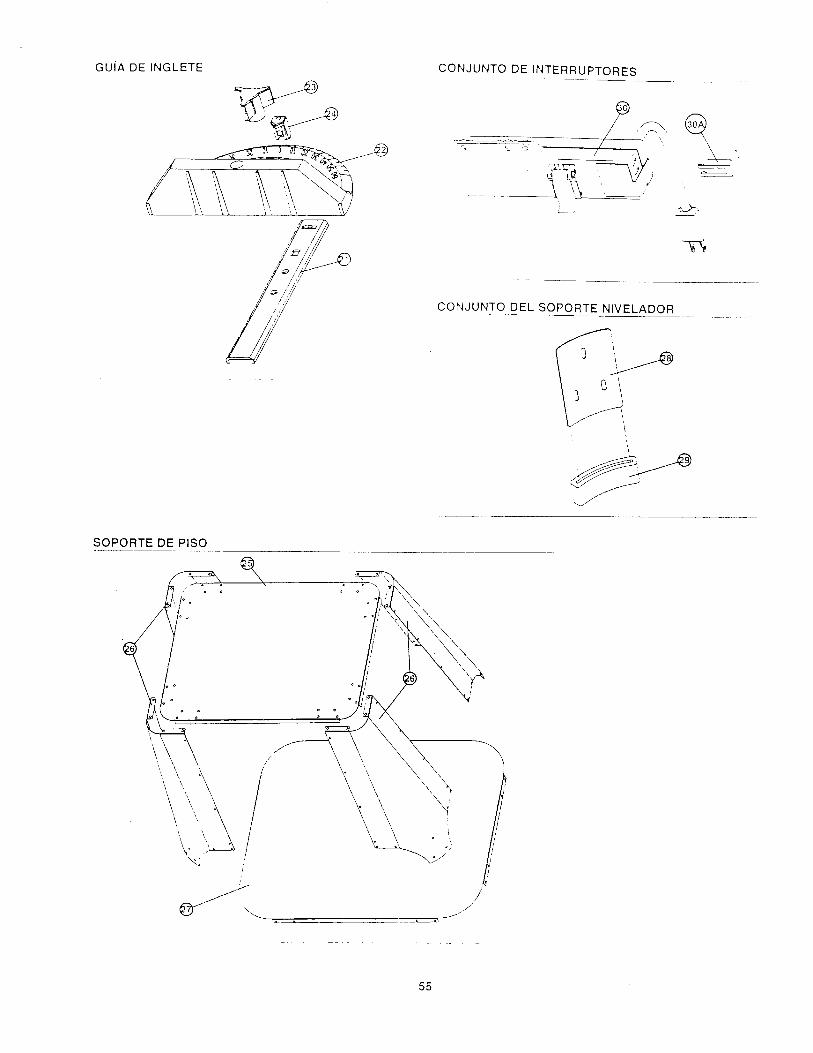
GUiA DE INGLETE CON JUNTO DE INTERRUPTORES
< /_'
CON JUNTO DEL SOPORTE NIVELADOR
SOPORTE DE PISO
\ \.
\\
\\
55

For Missing Partsor
Technical AssistanceCall
1-800-624-0488
When corresponding, always give the followinginformation as shown in the list.
1. The PART NUMBER
2. The PART DESCRIPTION
3. The MODEL NUMBER: 171.254841
4. The ITEM NAME - PROFESSIONAL ROUTING
CENTER
Para obtener cualquierpieza faltante o asistencia
tecnica, Ilame al1-800-624-0488
Cuando corresponda, de siempre la siguiente informa-cion indicada en la lista.
Printed in U.S.A.
Impreso en los Estados Unidos01 ,"99
1. NUMERO DE PIEZA
2. DESCRIPCION DE LA PIEZA
3, NUMERO DE MODELO: 171.254841
4. NOk,'IBRE DEL ARTICULO - CENTRO
PROFESIONAL DE FRESADO
r