Manual No.: 16617025 Instruction Manual Revision A Date of ...
40
Duramin-100 Instruction Manual Manual No.: 16617025 Revision A Date of Release 2018.08.10
Transcript of Manual No.: 16617025 Instruction Manual Revision A Date of ...

Duramin-100 Instruction Manual
Manual No.: 16617025 Revision A
Date of Release 2018.08.10

Duramin-100 Instruction Manual
2

Duramin-100 Instruction Manual
3
Automatic Micro/Macro hardness tester for Automatic Micro/Macro hardness testing of solid materials. The machine is designed to be used with indenters specially designed for this purpose and fixed in the turret of the motorized test head. Samples are secured on a fixed anvil or optional motorized XY-stage. For load ranges 10 gf-62.5 kgf, 10 gf-150 kgf, and 10 gf-250 kgf The hardness tester meets the applicable DIN, ISO-EN, ASTM and JIS standards. The machine is for use in a professional working environment (e.g. a materialography laboratory). Duramin-100 AC1/AC2/AC3
Intended use:
Models:
IMPORTANT
READ the instruction manual carefully before use. Keep a copy of the manual in an easy-to-access place for future
reference.

Duramin-100 Instruction Manual
4
Always state Serial No and Voltage/frequency if you have technical questions or when ordering spare parts. You will find the Serial No. and Voltage on the type plate of the machine itself. We may also need the Date and Article No of the manual. This information is found on the front cover. The following restrictions should be observed, as violation of the restrictions may cause cancellation of Struers legal obligations: Instruction Manuals: Struers Instruction Manuals may only be used in connection with Struers equipment covered by the Instruction Manual. Struers assumes no responsibility for errors in the manual text/illustrations. The information in this manual is subject to change without notice. The manual may mention accessories or parts not included in the present version of the equipment. Original instructions. The content of this manual are the property of Struers. Reproduction of any part of this manual without the written permission of Struers is not allowed. All rights reserved. © Struers 2018. Struers Pederstrupvej 84 DK-2750 Ballerup Denmark Telephone +45 44 600 800 Fax +45 44 600 801

Duramin-100 Instruction Manual
5
Duramin-100 Safety Precaution Sheet
Read carefully before use
1. Ignoring this information and mishandling of the equipment canlead to severe bodily injuries and material damage.
2. The operator(s) must read the Safety and User’s Guide sectionsof this manual and the relevant sections of the manuals for anyconnected equipment and accessories.
3. The machine must be installed in compliance with local safetyregulations.
4. Do not operate the equipment at a voltage other than the powervoltage that is indicated. Doing so can cause fires.
5. Do not twist or damage the power cords. Damaged power cordscan cause fire and/or electric shock.
6. Do not block the ventilation. Blocking the ventilation can causeheat to accumulate inside the machine, which in turn, cangenerate fire.
7. The machine must be placed on a safe and stable support.Failure to do so can affect the proper working and cause theequipment to fall down and/or cause accidents and injuries. Allsafety functions and guards of the machine must be in workingorder.
8. Do not modify this equipment. Doing so can cause fire and/orelectric shock.
9. Do not disassemble this equipment. Doing so can cause electricshock.
10. Do not open any panel on the machine. High voltages existinside the machine and may cause electrical shocks topersonnel.

Duramin-100 Instruction Manual
6
11. Do not allow the machine to become wet. Fires can occur ifwater gets inside the equipment. If water or other liquid does getinside the equipment, turn off the power to the equipment’s mainunit, disconnect the power supply, and call technical service.
12. In case of fire, alert bystanders, the fire brigade and cut power.Use a powder fire extinguisher. Do not use water.
13. Do not connect/ disconnect power with wet hands. Doing so canresult in electric shock.
14. If malfunctions, smoke or unusual noises are observed - turn offthe power, disconnect the power supply and call technicalservice.
15. Disconnect the power supply prior to any cleaning, maintenanceor service.Failure to do so can result in electric shock.
16. If two persons work together, make sure to communicate clearlyto avoid injuries.
The equipment should only be used for its intended use and as detailed in the Instruction Manual.
The equipment is designed for use with accessories supplied by Struers. If subjected to misuse, improper installation, alteration, neglect, accident or improper repair, Struers will accept no responsibility for damage(s) to the user or the equipment.
Dismantling of any part of the equipment, during service or repair, should always be performed by a qualified technician (electromechanical, electronic, mechanical, pneumatic, etc.)

Duramin-100 Instruction Manual
7
Icons and typography
Struers uses the below icons and typographical conventions. A list of the Safety Messages used in this manual can be found in the chapter on Cautionary Statements.
ELECTRICAL HAZARD indicates an electrical hazard which, if not avoided, will result in death or serious injury.
DANGER indicates a hazard with a high level of risk which, if not avoided, will result in death or serious injury.
WARNING indicates a hazard with a medium level of risk which, if not avoided, could result in death or serious injury.
CAUTION indicates a hazard with a low level of risk which, if not avoided, could result in minor or moderate injury.
CRUSHING HAZARD indicates a crushing hazard which, if not avoided, could result in mi-nor, moderate or serious injury.
NOTE: indicates a risk of damage to property, or the need to proceed with special care.
HINT: indicates additional information and tips.
Icons and Safety Messages
General Messages

Duramin-100 Instruction Manual
8
The 'colour inside' logo on the cover page of this Instruction Manual indicates that it contains colours which are considered to be useful for the correct understanding of its contents. Users should therefore print this document using a colour printer.
Bold type indicates button labels or menu options in software programs
Italic type indicates product names, items in software programs or figure titles
Bullets indicates a necessary work step
Colour Inside Logo
Typographic conventions

Duramin-100 Instruction Manual
9
Page Table of Contents
1.Getting StartedGeneral Device Description ............................................................. 11 Unpacking Duramin-100 .................................................................. 11 Location .......................................................................................... 12 Lifting Duramin-100 ......................................................................... 13 Placing Duramin-100 ....................................................................... 14
Levelling ................................................................................. 14 Removing the Lifting Bar ........................................................ 14 Removing the Transport Plate ................................................ 15
Checking the Contents .................................................................... 16 Getting Acquainted with Duramin-100 ............................................. 17
USB Drive and WiFi Adapter .................................................. 18 Rear plate .............................................................................. 18
Power Supply .................................................................................. 19 Connecting the Tester ............................................................ 19
Assembling the Monitor ................................................................... 20 Connecting the Monitor .......................................................... 21
Installing an XY-Stage ..................................................................... 22
2.Basic OperationsFront Panel Controls ....................................................................... 23 Software .......................................................................................... 24 Start-up ........................................................................................... 24 Overview Screen ............................................................................. 26
Main Menu ............................................................................. 26 Test Result Window ............................................................... 26 Test Settings .......................................................................... 26 Graph ..................................................................................... 26 Dashboard Controls ............................................................... 26
Perform a Test ................................................................................ 27
3.MaintenanceGeneral Cleaning ............................................................................ 28 Daily Maintenance ........................................................................... 28 Weekly Maintenance ....................................................................... 28
Cleaning Surfaces .................................................................. 28 Weekly Inspection .................................................................. 28
Yearly Safety Test ........................................................................... 28 Replacing the Fuse ......................................................................... 29 Calibration ....................................................................................... 29
4.Struers Knowledge ................................................................. 30
5.Trouble-Shooting .................................................................... 31
6.Service ...................................................................................... 32

Duramin-100 Instruction Manual
10
7.Disposal .................................................................................... 33
8.Transport and Storage ........................................................... 34
9.Cautionary Statements .......................................................... 35 List of Safety Messages in the Manual ............................................ 35
10.Legal and Regulatory ........................................................... 36 FCC Notice ..................................................................................... 36
11.Technical Data ...................................................................... 37

Duramin-100 Instruction Manual
11
1. Getting Started Duramin-100 is an automatic hardness tester that offers the most common-used hardness testing methods for all types of stable and non-explosive metals. The test operator starts the procedure by positioning – and eventually – securing the sample to the anvil or stage. A wide range of clamping tools and vices are available to fit your needs. Via the included software, the operator selects the test type and presses start on the stand-alone touch screen. The software calculates the values instantly and stores them on the internal hard drive. Afterwards, the data can be moved to a memory stick or to a network drive. In the unlikely situation of an accident or unforeseen incident, the operator can hit the emergency stoop to bring the machine to a standstill Refer to the DURAMIN-100: HOW TO UNPACK instructions delivered with Duramin.
NOTE: Take care whilst handling Duramin. Do not expose to external impact. Do not tilt over 30 degrees. Do not touch the turret. NOTE: Store the packing crate and foam packaging for use whenever Duramin is transported/re-located. Failure to use the original packaging and fittings could cause severe damage to the tester and will void the warranty. Carefully open and remove the top of the packing crate. Remove one side of the packing crate. Remove the monitor, box of accessories and other loose items. Carefully lift the foam pieces to access Duramin. Remove the plastic covering.
General Device Description
Unpacking Duramin-100

Duramin-100 Instruction Manual
12
Duramin must be placed close to the power supply. Duramin is designed to be placed on a rigid, stable workbench
with a horizontal surface.
Recommended workbench dimensions. Height of table (X) follows local preferences.
To facilitate easy access for service technicians, allow sufficient space around the machine. Install Duramin in a vibration-free location.
NOTE: Vibrations can lead to inaccurate measurements and must be avoided. A simple way of detecting vibrations is to set up a tray of water and watch for ripples on the surface.
HINT: Sources of vibration can include: Passers-by (persons walking past), a road with heavy traffic, cranes, equipment generating vibrations, equipment generating sound (acoustic vibration), exposure to wind or air conditioning fans. If possible, install the hardness tester on the ground floor of a building and away from exits or doorways.
Location
Vibration-free Location

Duramin-100 Instruction Manual
13
A crane, lifting bar (approx. 75cm length, 25mm diameter) and lifting straps1 are required to lift the machine from the packing crate. The crane should have a minimum lifting capacity of twice the weight of the machine.
NOTE: Take care whilst handling Duramin. Do not expose to external impact. Do not tilt over 30 degrees. Do not touch the turret. Check that the crane has a free pathway from the lifting point to
the final location.
Remove the bolts that secure the transportation plate to the pallet.
Remove the plastic hole covers. Insert the lifting bar. Place the lifting straps securely around the lifting bar. Ensure that
the straps do not press on the tester. Carefully lift Duramin out of the packing crate. While lifted, remove the transportation plate. Mount the four adjustable vibration dampers . Make sure that the dampers are of equal height. Lift Duramin to its final location.
NOTE: DO NOT place the lifting bar or the lifting straps through the space in the tester’s cover.
1 Lifting straps must be approved to at least twice the weight of the machine.
Lifting Duramin-100

Duramin-100 Instruction Manual
14
To eliminate possible wear and tear or the tester’s mechanical structure, the tester should be levelled once it is in its final location. Check that the XY-stage is level. If not: Turn the vibration damper in the rear right hand corner, to level
the XY-stage.
Remove the lifting bar. Re-mount the two black hole covers.
NOTE: Keep the lifting bar for future use.
Placing Duramin-100 Levelling
Removing the Lifting Bar

Duramin-100 Instruction Manual
15
Remove the transport safety before turning on the tester. The motorized XY-stage will automatically move to perform a reference search on initialization.
NOTE: Damage to the stage will result if the tester is switched on with the transport safety plate mounted. Unscrew the six screws securing the transport safety plate at the rear. Keep the plate and screws for use whenever the machine is to
be relocated.
Removing the Transport Plate (Motorized XY-stage option only)

Duramin-100 Instruction Manual
16
In the packing crate you should find the following parts: 1 Duramin-100 (Hardness Tester) 1 Accessories Case 1 15“ Monitor (2nd monitor optional) 1 Keyboard (Option) 1 Mouse (Option) Indenter(s) and objective lens(es) 1 Wireless Mouse and keyboard (Option) 2 Power cables 1 USB cable to monitor 1 HDMI to DVI cable 1 Spare fuse 1 Certificate of calibration on USB 1 USB Wi-Fi Adapter 1 Cables for motorized XY-stage (Option) 1 ASUS Bluetooth dongle (Option) Please consult your order confirmation to check that all the accessories ordered are included in the delivery.
HINT: Some components or parts may be packaged separately and may not be included in the accessory case or may have been installed on the hardness tester. HINT: The actual packaging and accessories may appear different to those shown in the picture.
Checking the Contents
Accessories Case Standard Accessories
Optional Accessories

Duramin-100 Instruction Manual
17
Take a moment to familiarise yourself with the location and names of the Duramin-100 components.
1. Turret 2. XY-stage 3. Z-axis control buttons 4. Emergency stop 5. Scroll wheel for fine fo-
cus 6. Levelling adjustment 7. Hole for lifting bar 8. QR code 9. Touchscreen monitor 10. XY-stage connection
11. Main Power 12. Main power connection 13. USB connections 14. HDMI connection 15. Network (RJ-45 LAN con-
nection)
Getting Acquainted with Duramin-100
Power Connections

Duramin-100 Instruction Manual
18
The USB drive contains direct and indirect calibration documents.
The USB WiFi adapter allows for cable-free communication with the machine.
Information on the model number, serial number, weight, date of manufacture, and power requirements can be found on the type plate on the back of the machine.
USB Drive and WiFi Adapter
Rear plate

Duramin-100 Instruction Manual
19
Always remember to switch the power off when installing electrical equipment!
ELECTRICAL HAZARD The machine must be earthed. Check that the mains voltage corresponds to the voltage stated on
the type plate on the side of the machine. Incorrect voltage may result in damage to the electrical circuit.
Duramin-650 is shipped with 2 types of Mains cables: The 2-pin (European Schuko) plug is for use on single-phase connections. If the plug supplied on this cable is not approved in your country, then the plug must be replaced with an approved plug. The leads must be connected as follows: Yellow/green: earth (ground) Brown: line (live) Blue: neutral The 3-pin (North American NEMA 5-15P) plug is for use on single -phase connections. If the plug supplied on this cable is not approved in your country, then the plug must be replaced with an approved plug. The leads must be connected as follows: Green: earth (ground) Black: line (live) White: line (live) Standard IEC 320 connector: Connect the power cable to the machine. (IEC 320 connector). Connect to the mains power supply.
Power Supply Connecting the Tester
Connection to the Machine

Duramin-100 Instruction Manual
20
Contents of the monitor box: 1 monitor with base 1 HDMI-DVI cable 1 USB cable, and European power cords.
HINT: The dual monitor option will be delivered with 2 monitor boxes. Remove the monitor’s rear panel. Slide the panel off to expose the connection ports.
Remove the two black plastic pieces around the monitor stand
joint. Adjust the stand angle.
If necessary loosen the two nuts around the joint using a 13 mm hexagonal wrench.
Lay the monitor face down on a flat surface. Unscrew the four screws on the rear of the monitor. Position the stand on the back of the monitor and line up the four
holes with the four screw holes. Check that the label TOP will be at the top of the monitor when it is upright.
Tighten the four screws to attach the monitor to the stand.
Assembling the Monitor

Duramin-100 Instruction Manual
21
Plug the USB cable into the USB port, HDMI cable to the HDMI port, and the power cord adapter to the power port on the rear of the tester.
Check that all plugs are connected correctly and replace the rear panel of the monitor.
NOTE: Only monitors supplied by Struers may be connected to Duramin. Failure to adhere to this may result in material damage. The monitors will be labelled Screen L and Screen R. The ports at the rear of the Duramin will also be labelled Screen L and Screen R.
Connect the correct USB and HDMI cables to the corresponding
Screen L and Screen R ports. The power cable for the 2nd monitor must be plugged into a
mains power socket. The mains power socket must be easily accessible and located between 0.6 m - 1.9 m (2½” – 6’) above floor level. (An upper limit of 1.7 m (5’ 6”) is recommended).
Connecting the Monitor
Dual Monitor Option

Duramin-100 Instruction Manual
22
HINT: The XY-stage is usually delivered already mounted on the machine.
NOTE:. Switch Duramin OFF at the mains when installing or /removing an XY-stage. Failure to comply may result in damage to the tester. Move the spindle to its top position. Use a soft cloth to wipe any dirt or debris from the mat surfaces
of the dovetail connection. Carefully slide the stage into the dovetail connection. Tighten the fixation screw to secure the stage in place. Connect the cable to the motorized XY-stage and to the
connection on the machine.
Perform a few hardness tests on a dummy sample to securely
seat the stage.
NOTE: The Duramin software must be configured correctly when a motorized XY-stage is mounted or removed. NOTE: The range of force that can be applied is limited when using an XY-stage. Check that XY-stage is set to On in the Duramin software. Failure to do so may result in overload and possible damage to the stage. Excessive overload may result in irreparable damage!
Installing an XY-Stage
Connection for motorized XY-stage
Dovetail connection
Fixation screw

Duramin-100 Instruction Manual
23
2. Basic Operations
1. Spindle up/down 2. Scroll wheel for fine
adjustment 3. Emergency stop
MAIN SWITCH The main switch is located on the rear of the machine. The main switch will be illuminated when the power is turned on.
The EMERGENCY STOP is located on the front of the machine. Emergency Stop − Push the red button to Activate. − Turn the red button clockwise to Release.
NOTE: Do not use the Emergency stop for operational stop of the machine during normal operation. BEFORE releasing (disengaging) the Emergency stop, investigate the reason for activating the Emergency stop and take any necessary corrective action.
Front Panel Controls

Duramin-100 Instruction Manual
24
Duramin-100 is operated through the Duramin software. A short description of the software is included in this manual. Please refer to the Duramin software manual for a detailed description of the software functions. Switch the machine on.
The Duramin software will initialize and the following progress bar will appear on the monitor:
HINT: Make sure that the emergency stop is not activated during start-up. After initialization, the following screen appears:
Alternatively, use the external keyboard and mouse to operate Duramin-100. Your first Username and password.
Username: Admin Password: none
Press Ok.
Software
Start-up
The actual screen may appear different depending on the configuration and model of the Duramin-100.
To prevent scratching the screen, avoid using sharp objects

Duramin-100 Instruction Manual
25
HINT: The default username is not case sensitive. HINT: For instructions on how to add new users, please refer to the Software manual. If the emergency stop is activated during start-up, a failure message will appear. Release the emergency stop. Press System, then Exit.
Switch Duramin Off using the Main switch, then switch on again
to start initialization.
Start-up After Emergency Stop
Exit

Duramin-100 Instruction Manual
26
The overview screen is primarily divided into 5 main areas.
The Main Menu is used to select the test method and scale required as well as adjusting settings and other functions. The Test Result Window shows an image of the indent (or the indent pattern) and a list of the indents performed. The Test Settings menus are used to select test patterns and to perform additional functions. The Graph shows an illustration of the results obtained. The Dashboard Controls are used to move the turret and select the indenter or objective to be used, fine positioning of the spindle light controls and to start the indentation process.
HINT: Please refer to the Duramin Software manual for a detailed description of the software and its functions.
Overview Screen
Main Menu
Test Result Window
Test Settings
Graph
Dashboard Controls
Main Menu
Objective view
Dashboard Controls
Test settings
Graph
Test result

Duramin-100 Instruction Manual
27
Consider the following as your basic test. Follow these steps: Check that the sample surface is smooth and even. Check that the sample surface is free from oxide scale, foreign
matter and completely free from lubricants. Setup the tester with the required type of test, scale (load) and
required indenter. Place the specimen on the anvil / XY-stage. .
Press Start to start the test. The testing procedure will proceed automatically.
.
The start button will turn into a red stop button. Press Stop to interrupt the test. (Do not use the Emergency Stop unless necessary).
CAUTION Do not place your hand between the sample and the indenter.
NOTE: The first reading on the sample should not be considered in the statistics.
Perform a Test
Starting the test

Duramin-100 Instruction Manual
28
3. Maintenance Keep Duramin-100 as clean as possible.
To ensure a longer lifetime for your equipment Struers strongly recommends regular cleaning.
Clean all accessible surfaces with a soft, damp cloth.
HINT: Do not use a dry cloth as the surfaces are not scratch resistant. Do not use aggressive or abrasive products. Grease and oil can be removed with ethanol or isopropanol.
NOTE: Never use acetone, benzol or similar solvents. Clean painted surfaces and the control panel with a soft damp
cloth and common household detergents. Inspect the following parts before every hardness test or at least
weekly. Part Attention Action Precaution Indenter Tip dirty Wipe
indenter Do not bend the indenter shaft
Objective or lens
Lens surface polluted
Wipe lens Do not scratch the objective or lens
Anvil Rust Remove rust
Do not bring the stage into contact with the turret.
Test block Rusted Replace test block
Do not use rusted test blocks
The emergency stop is the only safety device on a Duramin. Follow these steps to test it:
Start the machine. Hit emergency stop.
If the machine powers off, all is OK. If the machine does not stop, call Struers Service.
General Cleaning
Daily Maintenance Machine
Weekly Maintenance Cleaning Surfaces Weekly Inspection
Yearly Safety Test
Duramin-100 Instruction Manual
29
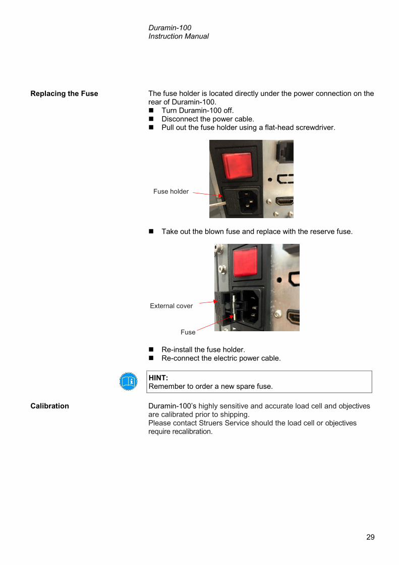
The fuse holder is located directly under the power connection on the rear of Duramin-100. Turn Duramin-100 off. Disconnect the power cable. Pull out the fuse holder using a flat-head screwdriver.
Take out the blown fuse and replace with the reserve fuse.
Re-install the fuse holder. Re-connect the electric power cable.
HINT: Remember to order a new spare fuse. Duramin-100’s highly sensitive and accurate load cell and objectives are calibrated prior to shipping. Please contact Struers Service should the load cell or objectives require recalibration.
Replacing the Fuse
Calibration
Fuse holder
External cover
Fuse

Duramin-100 Instruction Manual
30
4. Struers Knowledge The need for fast, robust and well proven test methods for materials verification is inevitable. Vickers, Knoop, Rockwell and Brinell methods, with a countless number of loads and indenter geometries, gives an almost countless number of procedures, suitable for simple characterization of a large fraction of existing materials.
HINT: Visit the Struers Hardness testing website for a comprehensive introduction to the principles of hardness testing, useful troubleshooting tips and the latest application knowledge in the field. Click on the link: Struers - Ensuring Certainty / Knowledge / Hardness testing OR Scan the QR code on the Duramin tag on your machine to go to the web-site.

Duramin-100 Instruction Manual
31
5. Trouble-Shooting Some of the minor malfunctions can be resolved by restarting the tester: Press System, then Exit. Click on the exit icon on the taskbar to shut down the embedded
PC.
Switch Duramin Off, then switch on again to start initialization.
NOTE: Failure to follow the above procedure may cause you to loose all your stored data.
Error Explanation Action Start-up failure The emergency stop is activated - Release the emergency stop.
- Restart the tester. Max down reached! The maximum down position of the
force actuator has been reached.
Motor failure! Failure of force application motor. - Restart the tester. If the error remains, contact Struers Service.
System not initialized! Failure of Software communication. - Restart the tester. If the error remains, contact Struers Service.
Failed to open connection to AUX on EURP AUX Virtual Com Port (COM3)
Failure of Software communication. - Restart the tester. - Press System, then Exit. - Switch Duramin Off, then switch
on again to start initialization. If the error remains, contact Struers Service.
Load motor is not in home position - Press Escape. - Then press Start. If this does not help, - Restart the tester. If the error remains, contact Struers Service.
Exit

Duramin-100 Instruction Manual
32
6. Service Struers recommends that a regular service check be carried out after every 1500 hours of use. Servicing must be carried out by Struers Field Engineers, or skilled personnel specifically trained by Struers.
NOTE. Safety critical components must be replaced at least after a lifetime of 20 years2. Contact Struers Service for information. Struers offers a range of comprehensive maintenance plans to suit the requirements of our customers. This range of services is called ServiceGuard. The maintenance plans include equipment inspection, replacement of wear parts, adjustments/calibration for optimal operation, and a final functional test.
2 According to EN ISO 13849-1

Duramin-100 Instruction Manual
33
7. Disposal
Equipment marked with a WEEE symbol contain electrical and electronic components and must not be disposed of as general waste. Please contact your local authorities for information on the correct method of disposal in accordance with national legislation.

Duramin-100 Instruction Manual
34
8. Transport and Storage
NOTE: Store the packing crate, foam packaging, bolts and fittings for use whenever Duramin is transported/re-located. Failure to use the original packaging and fittings could cause severe damage to the tester and will void the warranty. Follow these steps: 1. Familiarize yourself with the DURAMIN-100: HOW TO UNPACK
document 2. Disconnect Duramin from power. 3. Mount the transport plate on the motorized XY-stage (if present). 4. Place the lifting straps3 securely on the lifting bar. 5. Move the machine to its new position. If the machine is bound for long-time storage or shipping, follow these steps: 6. While lifted, remove the feet. 7. Line up the holes on the transport plate with the bolts on the ma-
chine. Fasten the machine to the plate. 8. Place the machine on the pallet. 9. Secure the transport plate with bolts and nuts to the pallet. 10. Mount the sides of the crate. 11. Place the accessories box, and other loose items in the crate. To
keep the machine dry, place a desiccant (silica gel) in the box, too.
12. Mount the lid of the crate.
NOTE: Always use the lifting bar when moving the machine. Failure to use the lifting bar could cause severe damage to the machine and will void the warranty. NOTE: Always transport the hardness testing machine in an upright position. NOTE: DO NOT ship or transport the tester without the correct packing materials.
3 Lifting Straps must be approved to at least twice the weight of the machine.

Duramin-100 Instruction Manual
35
9. Cautionary Statements
ELECTRICAL HAZARD The machine must be earthed. Check that the mains voltage corresponds to the voltage stated on
the type plate on the side of the machine. Incorrect voltage may result in damage to the electrical circuit.
CAUTION Do not place your hand between the sample and the indenter.
List of Safety Messages in the Manual

Duramin-100 Instruction Manual
36
10. Legal and Regulatory This equipment has been tested and found to comply with the limits for a Class A digital device, pursuant to Part 15 of the FCC Rules. These limits are designed to provide reasonable protection against harmful interference when the equipment is operated in a commercial environment. This equipment generates, uses, and can radiate radio frequency energy and, if not installed and used in accordance with the Instruction Manual, may cause harmful interference to radio communications. Operation of this equipment in a residential area is likely to cause harmful interference in which case the user will be required to correct the interference at his own expense. Pursuant to Part 15.21 of the FCC Rules, any changes or modifications to this product not expressly approved by Struers ApS could cause harmful radio interference and void the user’s authority to operate the equipment
FCC Notice

Duramin-100 Instruction Manual
37
11. Technical Data
Subject Specifications Electrical Data Power supply 100 V AC – 240 V AC, 50/60Hz,
single phase
Power consumption (Idle) 60 W
Power consumption (Load) 72 W
Power consumption (Max) 159 W
Power consumption (Standby) 30 W
Residual Current Circuit Breaker
Type A, 30 mA is required.
Weight Duramin-100 M1/M2/M3 101 Kg/ 223 lbs
Duramin-100 A1/A2/A3 112 Kg/ 247 lbs
Duramin-100 AC1/AC2/AC3 112 Kg/ 247 lbs
Operating Environment
Noise level Less than 70 dB (A) measured at idle running, at a distance of 1.0 m/39.4” from the machine.
Surrounding temperature 10-35 °C / 40-105 °F Recommended: 21 ± 3 °C / 70 ± 5 °F
Humidity 10%-90% RH (Non-condensing) NOTE: No condensation may form on the machine.
Safety standards
Please refer to the Declaration of Conformity
HINT: Please refer to the Duramin-100 brochure for further details.

Duramin-100 Instruction Manual
38

Duramin-100 Instruction Manual
Contents of the Declaration of Conformity Manufacturer Struers ApS
Pederstrupvej 84 DK-2750 Ballerup, Denmark Telephone +45 44 600 800
Herewith declares that Name: Models: Function: Type:
Duramin-100 AC1/ AC2/ AC3 Hardness Tester 066161XX
fulfils all the relevant provisions of the: Machinery Directive 2006/42/EC
and is in conformity with the: EMC Directive 2014/30/EC
RoHS Directive 2011/65/EU
Supplementary Information
according to the following standard(s): EN ISO 12100:2010, EN ISO 13849-1:2008/AC:2009, EN ISO 13850:2008, EN 60204-1:2006/AC:2010.
according to the following standard(s): EN 55011:2009/A1:2010, EN61326-1:2013, EN 61000-3-2:2014, EN 61000-3-3:2013. according to the following standard(s): EN 50581:2012.
The equipment complies with the following standards:
The above has been declared according to the global approach, module A.
Authorized to compile the Technical File:
Klavs Tvenge Director of Business Development Struers ApS Pederstrupvej 84 DK-2750 Ballerup, Denmark
39

Pederstrupvej 84 DK-2750 Ballerup Denmark