Manual Microwave Pulse Switch - Hawk Measure manual.pdf · Shiploader/Stacker/Reclaimer MPS - MPR...
35
Manual Flow/no flow. Plugged/blocked chute detection. Low level measurement (bins, crushers etc). High level measurement (bins, crushers etc). Product on conveyor detection. Rail/truck load out position detection. • • • • • • Anti-collision crane detection. Blocked feeder pipes for pneumatic and dense phase filling, air slides etc. Replacement of tilt switches. Versatile Power Supply 90-250VAC 24VDC, 48VDC. Certification ATEX, SAA/IECEx, CE, (CSA, FM pending) • • • • • Typical Uses: Microwave Pulse Switch Solid/Liquid Level 10.525GHz Sender/Receiver Remote & Integral Versions A higher level of performance SAFE ALTERNATIVE TO NUCLEAR SWITCHES REPLACES TILT SWITCHES MRA - MRS - MRR Remote Microwave Pulse Switch (Standard) MRA - MRS-H - MRR-H Remote Microwave Pulse Switch (Hi Power) MRA - MRRH3-00 - MRR-H - MRSH - MRS Remote Microwave Pulse Switch. Shiploader/Stacker/Reclaimer MPS - MPR Integral Microwave Pulse Switch MSEQ SEQUENCER Multi unit sequencer MDS FLOW UNIT Installation and operating instructions Function Point level switching for presence or absence of solid and liquid materials. Environmentally and personally safe replacement for nucleonic switches. Not restricted by OSHA or FCC regulations. Caution sign posting not required. Primary areas of application Any application where microwave energy is absorbed ny application where microwave energy is absorbed by the material being monitored, including replacement of traditional contact switching devices used in mining, sand and gravel quarries, cement plants, pulp paper, plastic, rubber, coal fired power plants, steel mills, aluminium smelters, food, pharmaceuticals and other manufacturing
Transcript of Manual Microwave Pulse Switch - Hawk Measure manual.pdf · Shiploader/Stacker/Reclaimer MPS - MPR...

Manual
Flow/no flow.
Plugged/blocked chute detection.
Low level measurement (bins, crushers etc).
High level measurement (bins, crushers etc).
Product on conveyor detection.
Rail/truck load out position detection.
•
•
•
•
•
•
Anti-collision crane detection.
Blocked feeder pipes for pneumatic and dense phase filling, air slides etc.
Replacement of tilt switches.
Versatile Power Supply 90-250VAC 24VDC, 48VDC.
Certification ATEX, SAA/IECEx, CE, (CSA, FM pending)
•
•
•
•
•
Typical Uses:
Microwave Pulse Switch Solid/Liquid Level10.525GHz Sender/ReceiverRemote & Integral Versions
A higher level of performance
SAFEALTERNATIVETO NUCLEAR
SWITCHES
REPLACESTILT
SWITCHES
MRA - MRS - MRRRemote Microwave Pulse Switch (Standard)
MRA - MRS-H - MRR-HRemote Microwave Pulse Switch (Hi Power)
MRA - MRRH3-00 - MRR-H - MRSH - MRSRemote Microwave Pulse Switch. Shiploader/Stacker/Reclaimer
MPS - MPRIntegral Microwave Pulse Switch
MSEQ SEQUENCERMulti unit sequencer
MDS FLOW UNIT
Installation and operating instructions
FunctionPoint level switching for presence or absence of solid and liquid materials. Environmentally and personally safe replacement for nucleonic switches. Not restricted by OSHA or FCC regulations. Caution sign posting not required.
Primary areas of applicationAny application where microwave energy is absorbedny application where microwave energy is absorbed by the material being monitored, including replacement of traditional contact switching devices used in mining, sand and gravel quarries, cement plants, pulp paper, plastic, rubber, coal fired power plants, steel mills, aluminium smelters, food, pharmaceuticals and other manufacturing

Microwave Pulse Switch - Presence & Absence Detection MANUAL Rev 1.0
2
Proprietry Notice
The information contained in this publication is derived in part from proprietary and patent data. This informationhas been prepared for the express purpose of assisting operating and maintenance personnel in the efficient use of the instrument described herein.
Publication of this information does not convey any rights to use or reproduce it, or to use for any purpose other than in connection with the installation, operation and maintenance of the equipment described herein.
WARNING
This instrument contains electronic components that are susceptible to damage by static electricity. Proper handling procedures must be observed during the re-moval, installation, or handling or internal circuit boards or devices.
Handling Procedure1. Power to unit must be removed.2. Personnel must be grounded, via wrist strap or other safe, suitable means before any printed circuit board or other internal device isinstalled, removed or adjusted.3. Printed circuit boards must be transported in a con-ductive bag or other conductive container. Boards must not be removed from protective enclosure until the im-mediate time of installation. Removed boards must be placed immediately in a protective container for trans-port, storage, or return to factory.
Comments:
This instrument is not unique in its content of ESD (elec-trostatic discharge) sensitive components. Most modern electronic designs contain components that utilize metal oxide technology (NMOS, CMOS, etc.). Experience has proven that even small amounts of static electricity can damage or destroy these devices. Damaged com-ponents, even though they appear to function properly, exhibit early failure.
Introduction
Table of Contents
Principle of Operation 3
Specifications:Remote 4Integral 5Doppler 7
Facial Descriptions:Remote 8Integral 9Doppler 10
Applications 11
Special Application 12
Mounting 13
System Wiring, Setup & Calibration 18
Dimension Drawings & Diagrams 19
Sequencer Installation 27
Troubleshooting 28
Safety Information 33
Warranty 33
Part Numbering 34
Specifications 36

Microwave Series3
Sultan 234 Series
Microwave Pulse Switch - Presence & Absence Detection MANUAL Rev 1.0
REMOTE SYSTEM
The Hawk Microwave Pulse Sender-Receiver Remote System is comprised of three electrically isolated units:- the Sender, Receiver and Amplifier. The sender-receiv-er units are mounted facing each other. For best per-formance it is essential that they be mounted securely and correctly aligned.
The sender emits a burst of microwave energy toward the receiver, which is designed around a tuned mi-crowave detector. This burst of energy is transmitted approximately 200 times each second. While the line of sight is interrupted by a sufficiency reflective or absorb-ent material the energy will not reach the receiver, and therefore the receiver will not detect the transmission.
The receiver is designed to switch a relay when it’s detector changes state. Time delays between detec-tor change and relay switching is set via two single turn potentiometers; there is a potentiometer for the make (signal detected) delay and another for the break (signal interrupted) delay. In each case the relay will switch only after the detector state has been maintained (since it’s change) for the respective time: any further change of state during a time-out period will override the previous change.
The sensitivity of the detector is adjusted by a potentiom-eter. By this adjustment, compensation can be made for partially reflective or partially absorbing materials. Simi-larly, it can be adjusted so that it will change state when only a fraction of the beam is blocked. There are two sensitivity adjustment potentiometers, one for a coarse adjustment and the other for a fine adjustment.
In the Amplifier unit there are three LED lamps; one indi-cates that power is applied, another indicates that a valid signal is detected, and the other indicates that the relay is energized. In the sender unit the only lamp is the one indicating that power is applied.
INTEGRAL SYSTEM
The Hawk Microwave Pulse Sender-Receiver Integral System was created for process control applications requiring highly reliable non-contact absence/presence monitoring. The flexibility of the system allows for not only point level indication, but also flow/no flow, proximity sensing, absence/presence and plug chute detection in many different processes.
The Integral system consists of the Microwave Pulse Sender (MPS) unit and Microwave Pulse Receiver (MPR) unit. Each unit can be powered by 115Vac/240Vac or 24Vdc, mounted by flange or 3”NPT weld-
ment and is provided in an SM listed NEMA 4X enclo-sure for maximum flexibility.
The MPS unit has one LED indicator for power and a 100mA/250Vac fuse. It also has a TEST push-button for ease of setup and troubleshooting. Inside the MPR, there are three LED indicators for the following: power, signal detect and relay energized indications as well as a user accessible 100mA/250Vac fuse.
The MPS unit contains a tuned microwave diode that emits a continuous stream (approximately200 bursts each second) of microwave energy towards the MPR unit. The MPR contains a tuned microwave detector which will only accept signals from the MPS. When the sender and receiver are mounted in a direct line of sight and correctly aligned, the receiver will detect interrup-tions of these bursts. In effect, there is a microwave beam between the sender and receiver. While the line of sight is clear, the MPR will detect an uninterrupted stream. When the beam is interrupted by a sufficiently conductive material, the receiver detector will sense the interruptions and change states. This change of detec-tor states activates the relay, thus giving the basis for absence/presence indication.
Sensitivity of the receiver in the MPR is controlled by two single turn potentiometers: one for fine adjustment and the other for coarse adjustment. The sensitivity adjust-ment allows for compensation when monitoring partially conductive material. Similarly, it can be adjusted so that it will change state when only a fraction of the beam is interrupted.
The SPDT relay of the MPR unit can be set to either energize or de-energize when the beam is broken. This selection is made via the two-position slide switch next to the power input terminals.
The MPR unit also contains two time delays for control-ling and fine tuning its relay operation: the make (signal detected) and break (signal interrupted) adjustments. Each delay is independently adjustable by a single turn potentiometer from 100ms to 30 seconds. The relay will switch only after the detector state (signal/no signal) has been maintained for the time specified by the set point on the potentiometer. Any time there is a change in state, the timers are automatically reset.
For a more detailed list of specifications, please refer to the Specifications section of this manual.
Principle of Operation

Microwave Pulse Switch - Presence & Absence Detection MANUAL Rev 1.0
4
MDS DOPPLER SYSTEM
The Hawk MDS series microwave doppler flow switch was developed for use in process applications requiring highly reliable non-contact product flow detection. The system operates bysending out bursts of microwave energy toward the target product being monitored. The target product will reflect some of the microwave energy back to the MDS system where it is processed to deter-mine if the product is flowing.
The MDS system uses the Doppler principle to de-termine if the product is moving by monitoring small charges in the reflected signal frequency. When product flow is detected, a timer is initiated and after the user set time-out period, the relay output is switched. The system also has adjustable sensitivity to compensate for products that may partially reflect the microwave energy.
The SPST relay can be set to either energise or de-ener-gise when product flow is detected. Three LED indicators are provided to indicate power, flow detection, and relay energised status.
The system is available in either an integral or remote housing and is powered by 115Vac, 240Vac or 24Vdc. The system is housed in a FM listed NEMA 4X housing and is mounted using the standard 3 inch NPT weldment or flange.
Principle of Operation
Remote - MPA MRS/MRR MRS-H/MRR-H
Input Voltage: 240Vac nominal, 200-270Vac acceptable, 50-60 Hz 115Vac nominal, 100-130Vac acceptable, 50-60 HzAC supply line fuse: 100mA, 250VacAmplifier unit includes terminals for 24Vdc power supply
Power Consumption:MRA <5VA Remote Amplifier
Power Density: (MRS/MRR) (MRS-H/MRR-H)Rated from Sender to Receiver at approximately 20µW/cm2. No interconnecting wiring between Sender and Re-ceiver. Complies with FCC Title Rules Part 15. Caution sign posting not required.
Transmitted Signal:Frequency: 10.525 GHz, 25 MHzAverage Power Density: 20µW/cm typical linearly polar-ised fieldBeam angle (3dB) approximately 30° (conservative)
Range:Maximum range under ideal conditions:105m (340ft)Expected maximum practical range:65m (215ft)Minimum range under ideal conditions:10cm (4”)Expected minimum practical range:20cm (8”)(Note: Minimum ranges are dependent on application conductivity)
L.E.D IndicatorsMPS: power on (green)MPR: power on (green), signal detect (red), relay state (amber)
Mounting:3” male NPT thread or four 6mm (.250in)blind bolt holes in flange.a) 3” weldments supplied for standardintegral mounting.b) Flange is used for remote mount in highvibration applications - isoiation shockmounts are available.2. 4” weldments with PTFE (teflon), UHMW, ceramic, firebrick windows.3. Ceramic window assemblies - rectangular.4. Firebrick window assemblies available on custom basis - rectangular - circular.5. 2” NPT sight glass window.6. Waveguides - custom assemblies available.
Specifications - Remote

Microwave Series5
Sultan 234 Series
Microwave Pulse Switch - Presence & Absence Detection MANUAL Rev 1.0
Specifications Remote (con’t)
Adjustments:MPS: Test switch - momentary push-buttonMPR: Single turn coarse and single turn fine adjustment potentiometers for set point.Relay time delays adjustable from 100msto 30 seconds via two independenton/signal make and off/signal breakpotentiometers with automatic reset.
Fall-safe:Switch selectable - presence or absence ofmaterial.High level fail-safe position: relay is activated when ma-terial is presentLow level fail-safe position: relay is activated when no material is present
Temperature:MPS & MPR: -30°C to +65°C (-20°F to +150°F) Note: for higher temperature applications, remote mounting with windows is necessary. Customwaveguide assemblies can also be provided.UHMW Window: +80°C (+176°F)Ceramic Window: Consult factory formanufacturer’s specifications.Firebrick Assemblies: Consult factory formanufacturer’s specifications.
Cabling Entry(ies):MPS: 1 X 10mm (3/8” NPT)MPR: 2 X 10mm (3/8” NPT)
Relay Contact Output:MPR: SPDT - 10amps @ 250Vac resistive10amps @ 125Vac resistive
Enclosure:VALOXSAA LISTED
Specifications - Remote Specifications - Integral
Integral - MPS - MPR
Input Voltage:115Vac nominal, 100-130Vac acceptable, 50-60Hz240Vac nominal, 200-270Vac acceptable, 50-60HzAC supplys lined fuse: 100mA, 250VacBoth MPS & MPR units include terminalsfor 24Vdc supply power
Power Consumption:MPS < 2VAMPR < 3VA
Power Density:Rated from emitter (MPS) to receiver (MPR) at approxi-mately 20μW/cm . No interconnection wiring between emitter and receiver. Complies with FCC Title Rules Part 15. Caution sign posting not required.
Transmitted Signal:Frequency: 10.525 GHz, + 25 MHz
Average Power Density: 20RW/cm2 typical Linearly Polarized FieldBeam angle (3dB) approximately 30 degrees (conserva-tive)
Range:Maximum range under ideal conditions: 105m (340 ft.)Expected maximum practical range: 65m (215 ft.)Minimum range under ideal conditions: 10cm (4 in.)Range (cont): Expected minimum practical range: 20cm (8 in.)Note: Minimum ranges are dependent onapplication conductivity.
L.E.D. Indicators:MPS: power on (green)MPR: power on (green), signal detect (red), relay state (amber)
Mounting:1. 3” male NPT thread or four 6mm (.250in.) blind bolt holes in flange.a) 3” weldments supplied for standard integral mounting.b) Flange is used for remote mount in high vibration ap-plications - isolation shock mounts are available.2. 4” weldments with PTFE (teflon), UHMW, ceramic, firebrick windows.3. Ceramic window assemblies - rectangular.4. Firebrick window assemblies available on custom basis - rectangular - circular.5. 2” NPT sight glass window.6. Waveguides - custom assemblies available.

Microwave Pulse Switch - Presence & Absence Detection MANUAL Rev 1.0
6
Specifications Integral - MPS - MPR (con’t)
Input Voltage:115Vac nominal, 100-130Vac acceptable, 50-60Hz240Vac nominal, 200-270Vac acceptable, 50-60HzAC supplys lined fuse: 100mA, 250VacBoth MPS & MPR units include terminals for 24Vdc sup-ply power
Power Consumption:MPS < 2VAMPR < 3VA
Power Density:Rated from emitter (MPS) to receiver (MPR) at approxi-mately 20μW/cm . No interconnecting wiring between emitter and receiver. Complies with FCC Title Rules Part 15. Caution sign posting not required.
Transmitted Signal:Frequency: 10.525 GHz, + 25 MHz
Average Power Density: 20RW/cm2 typical Linearly Polarized FieldBeam angle (3dB) approximately 30 degrees (conserva-tive).
Range:Maximum range under ideal conditions: 105m (340 ft.)Expected maximum practical range: 65m (215 ft.)Minimum range under ideal conditions: 10cm (4 in.)Expected minimum practical range: 20cm (8 in.)Note: Minimum ranges are dependent onapplication conductivity.
L.E.D. Indicators:MPS: power on (green)MPR: power on (green), signal detect (red), relay state (amber)
Mounting:1. 3” male NPT thread or four 6mm (.250in.) blind bolt holes in flange.a) 3” weldments supplied for standardintegral mounting.b) Flange is used for remote mount in highvibration applications - isoiation shockmounts are available.2. 4” weldments with PTFE (teflon), UHMW, ceramic, firebrick windows.3. Ceramic window assemblies - rectangular.4. Firebrick window assemblies available on custom basis - rectangular - circular.5. 2” NPT sight glass window.6. Waveguides - custom assemblies available.Adjustments:
MPS: Test switch - momentary push-buttonMPR: Single turn coarse and single turn fine adjustment potentiometers for set point.Relay time delays adjustable from 100ms to 30 seconds via two independent on/signal make and off/signal breakpotentiometers with automatic reset.
Fall-safe:Switch selectable - presence or absence of material.High level fail-safe position: relay is activated when ma-terial is present.Low level fail-safe position: relay is activated when no material is present.
Temperature:MPS & MPR: -30°C to +65°C (-20°F to +150°F)Note: for higher temperature applications, remote mount-ing with windows is necessary. Custom waveguide as-semblies can also be provided.UHMW Window: +80°C (+176°F)Ceramic Window: Consult factory for manufacturer’s specifications.Firebrick Assemblies: Consult factory for manufacturer’s specifications.
Cabling Entry(ies):MPS: 1 X 10mm (3/8” NPT)MPR: 2 X 10mm (3/8” NPT)
Relay Contact Output:MPR: SPDT - 10amps @ 250Vac resistive10amps @ 125Vac resistive
Enclosure:VALOXSAA LISTEDMeets Class 2, Div 1, Group E, F & G (DlP-Dust Ignition Proof) classification.FM Approval Pending.Windows: UHMW (ultra-high molecular weight) polyeth-ylene standard PTFE (teflon) available,(see part numbering).
Sealing:IP67 (NEMA 4X)
Shipping Weights:MPS: 4.5kg (10 lbs.)MPR: 4.5kg (10 lbs.)

Microwave Series7
Sultan 234 Series
Microwave Pulse Switch - Presence & Absence Detection MANUAL Rev 1.0
Specifications - Doppler Switch
Doppler Switch - MDS
Input Voltage:240Vac nominal, 200-270Vac acceptable, 50-60 Hz115Vac nominal, 100-130Vac acceptable, 50-60 HzAC supply line fuse: 100mA, 250VacUnits have terminals for 24Vdc supply power.
Power Consumption:<3VA
Power Density:Rated from emitter at approximately 20μW/cm2. Complies with FCC Title Rules Part 15. Caution sign posting not required.
Transmitted Signal:Frequency: 10.525 GHz, ±25 MHzAverage Power Density: 20μW/cm2 typical Lin-early Polarised FieldBeam angle (3dB) approximately 30o(conservative)
Range:Maximum range under ideal conditions: 10m (33 ft.)Expected maximum practical range: 5m (16 ft.)Minimum range under ideal conditions: 0cm (0 in)Expected minimum practical range: 1cm (0.4 in)Note: Ranges are dependent on application reflectivity.
L.E.D. Indicators:Power on (green) Signal detect (red)Relay state (amber) EMI indicator (red)
Mounting:1. 3” male NPT thread or four 6mm(0.25 in.) blind bolt holes in flangea) 3” weldments supplied for standard integral mountingb) Flange is used for remote mount in high vibration applications-isolation shock mounts are available2. 4” weldments with PTFE (teflon) and UHMW windows3. Ceramic window assemblies4. Firebrick window assemblies available on custom basis5. 2” NPT sight glass window6. Flanged Pipe Mount.
Adjustments:Test switch - momentary push-buttonSingle turn coarse and single turn fine adjust-ment potentiometers for set point.
Relay time delays adjustable from 100ms to 30 seconds via two independent on/signal make and off/signal breakpotentiometers with automatic reset.
Fail-safe:Switch selectable - presence or absence of material flowHigh level fail-safe position: relay is activated when flow is presentLow level fail-safe position: relay is activated when no material flow is present
Temperature:-30°C to +65°C (-20°F to +150°F)Note: for higher temperature applications, remote mount-ing with windows is necessary. Custom waveguide as-semblies can also be provided.UHMW Window: Consult factory for manufacturer’s specifications.Firebrick Assemblies: Consult factory for manufacturer’s specifications.
Cabling Entry:3 x 10mm (3/8” NPT)
Relay Contact Output:SPDT - 10amps @ 250Vac resistive10amps @ 125Vac resistive
Enclosure:NEMA 4X. IP67/IP66SAA LISTEDMeets Class 2, Div 1, Group E, F & G (DIPDust Ignition Proof) classification.FM Approval Pending
Sealing:NEMA 4X
Shipping Weight:4.5kg (10lb)
Microwave Pulse Switch - Presence & Absence Detection MANUAL Rev 1.0
8
HILO
HILO
1
4
10
-30 sec0.3
1
4
10
-30 sec0.3
MPR-0LD1 -
APPLIED
Serial No. MXXXXXXX
MICROWAVE PULSE RECEIVERPOWER
LD2 -
LD3 -
DETECTEDSIGNAL
ENERGISEDRELAY
AFTER DELAY
RECEIVESENSITIVITY
(A=B)
ONDELAY
OFFDELAY
RV2
100mA
EUTR
AL
CTIV
E
ENA +24VAR
THEAR
TH
AC FUSEREV
RELAYNORM
RV1
RV2
P TSR U WVTO
MPS
FROMMPS
Polyester coatedmild steel pipe
1" N.P.T.
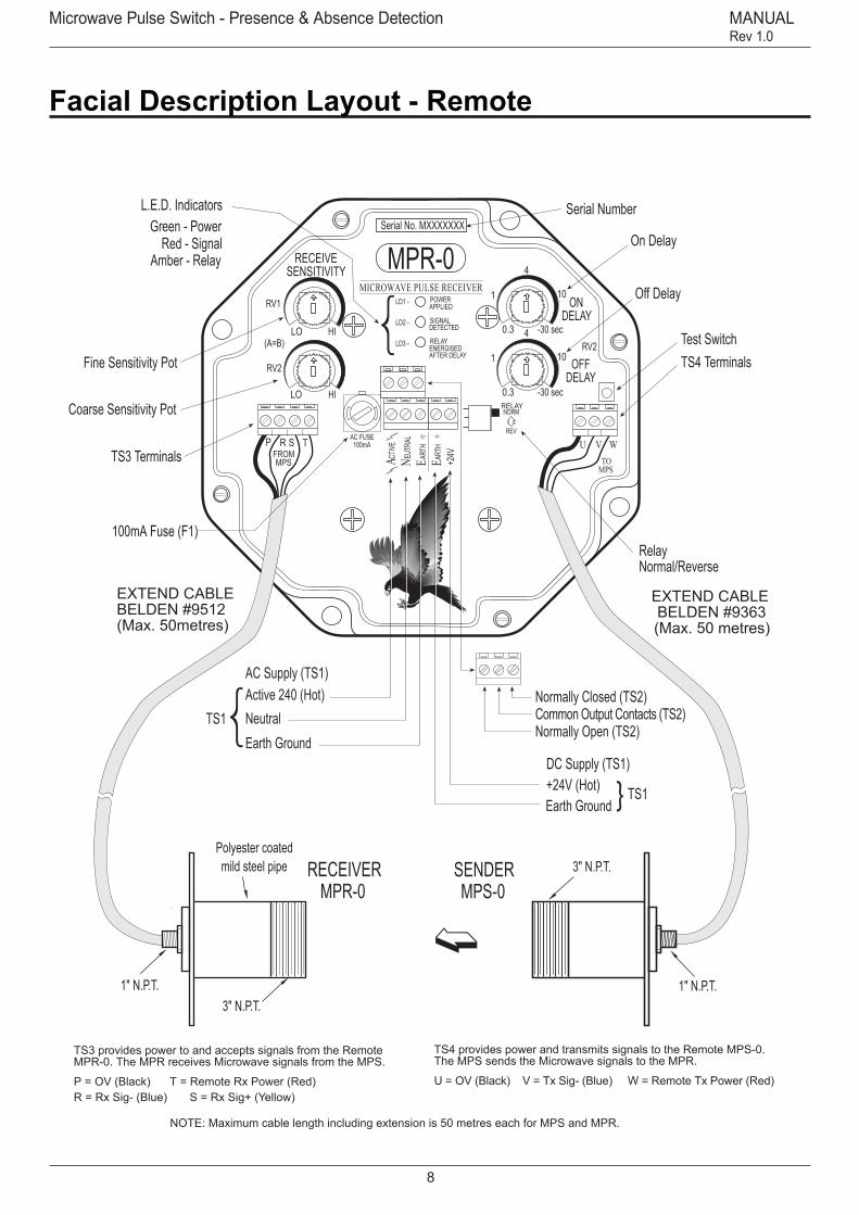
TS3 provides power to and accepts signals from the RemoteMPR-0. The MPR receives Microwave signals from the MPS.
P = OV (Black) T = Remote Rx Power (Red)R = Rx Sig- (Blue) S = Rx Sig+ (Yellow)
TS4 provides power and transmits signals to the Remote MPS-0.The MPS sends the Microwave signals to the MPR.
U = OV (Black) V = Tx Sig- (Blue) W = Remote Tx Power (Red)
NOTE: Maximum cable length including extension is 50 metres each for MPS and MPR.
RECEIVERMPR-0
3" N.P.T.
Active 240 (Hot)
Earth GroundNeutral
100mA Fuse (F1)
+24V (Hot)Earth Ground
Coarse Sensitivity Pot
Off Delay
On Delay
Normally Closed (TS2)Common Output Contacts (TS2)Normally Open (TS2)
DC Supply (TS1)
RelayNormal/Reverse
Serial Number
TS1
TS1
AC Supply (TS1)
Fine Sensitivity Pot
TS3 Terminals
TS4 TerminalsTest Switch
EXTEND CABLEBELDEN #9512(Max. 50metres)
EXTEND CABLEBELDEN #9363(Max. 50 metres)
Green - PowerL.E.D. Indicators
Red - SignalAmber - Relay
1" N.P.T.
SENDERMPS-0
3" N.P.T.
Facial Description Layout - Remote

Microwave Series9
Sultan 234 Series
Microwave Pulse Switch - Presence & Absence Detection MANUAL Rev 1.0
Facial Description Layout - Integral
MPR - RECEIVER
MPS - SENDER
100mA Fuse (F1)
Serial Number
Test Switch (SW1)(cancels MPS transmission)
Green - PowerL.E.D. Indicators
MPS-0LD1 -
APPLIED
Serial No. MXXXXXXX
MICROWAVE PULSE SENDERPOWER
DCINPUT
100mA
EUTR
AL
CTIV
E
ENA ARTH
AC FUSE
Active 240 (Hot)
Earth GroundNeutralTS1
AC Supply (TS1)+24V
OV (Ground)
DC Supply (TS2)
+24V
4OV
TEST
Not Used
Coarse Sensitivity Pot
100mA Fuse (F1)
Off Delay
On Delay
Normally Closed (TS2)Common Output Contacts (TS2)Normally Open (TS2)
RelayNormal/Reverse
Serial Number
Fine Sensitivity Pot
TP5 Positive
Green - PowerL.E.D. Indicators
Red - SignalAmber - Relay
HILO
HILO
1
4
10
-30 sec0.3
1
4
10
-30 sec0.3
MPR-0LD1 -
APPLIED
Serial No. MXXXXXXX
MICROWAVE PULSE RECEIVERPOWER
LD2 -
LD3 -
DETECTEDSIGNAL
ENERGISEDRELAY
AFTER DELAY
RECEIVESENSITIVITY
(A=B)
ONDELAY
OFFDELAY
RV2
100mA
EUTR
AL
CTIV
E
ENA +24VAR
THEAR
TH
AC FUSEREV
RELAYNORM
RV1
RV2
Active 240 (Hot)
Earth GroundNeutralTS1
AC Supply (TS1)
+24V (Hot)Earth Ground
DC Supply (TS1)
TS1
TP6 Gnd
SENS.LO HI
EMI IndicatorSensitivity Lo/Hi Switch
Alignmentindicator
0–2.8Vdc

Microwave Pulse Switch - Presence & Absence Detection MANUAL Rev 1.0
10
Facial Description - Doppler Switch
NOTE: Maximum cable length including extension is 50 metres.
HILO
HILO
1
4
10
-30 sec0.3
1
4
10
-30 sec0.3
MDALD1 -
APPLIED
Serial No. MXXXXXXX
MICROWAVE PULSE RECEIVERPOWER
LD2 -
LD3 -
DETECTEDSIGNAL
ENERGISEDRELAY
AFTER DELAY
RECEIVESENSITIVITY
(A=B)
ONDELAY
OFFDELAY
RV2
100mA
EUTR
AL
CTIV
E
ENA +24VAR
THEAR
TH
AC FUSEREV
RELAYNORM
RV1
RV2
P TSRRX
Active 115/240Vac
Earth Ground
Neutral
100mA Fuse (F1)
+24V (Hot)
Earth Ground
Sensitivity 'B' Pot
Off Delay
On Delay
Normally ClosedCommon Output ContactNormally Open
DC Supply
Relay mode
Serial Number
TS1
TS1
AC Supply
Sensitivity 'A' Pot
(TS3) Terminals
Test Switch
EXTEND CABLEBELDEN #9512(Max. 50 metres)
L.E.D. IndicatorsGreen - Power
Red - SignalAmber - Relay
(TP5) Positive(TP6) Gnd
EMI Indicator
P = OV (Black)S = Rx Sig (Blue)T = Remote Rx Power (Red)(Remote Version only)
To remote RX/TX Module(Remote Versions only)
1" BSPNipple
Polyester coated steel
3" N.P.T.
Remote RX/TX Module
MDR
Relay Terminals (TS2)

Microwave Series11
Sultan 234 Series
Microwave Pulse Switch - Presence & Absence Detection MANUAL Rev 1.0
HILO
HILO
1
4
10
-30 sec0.3
1
4
10
-30 sec0.3
MPR-0LD1 -
APPLIED
Serial No. MXXXXXXX
MICROWAVE PULSE RECEIVERPOWER
LD2 -
LD3 -
DETECTEDSIGNAL
ENERGISEDRELAY
AFTER DELAY
RECEIVESENSITIVITY
(A=B)
ONDELAY
OFFDELAY
RV2
100mA
EUTR
AL
CTIVE
ENA +24VAR
THEAR
TH
AC FUSEREV
RELAYNORM
RV1
RV2
P TSR U WVTO
MPSFROMMPS
HILO
HILO
1
4
10
-30 sec0.3
1
4
10
-30 sec0.3
MPR-0LD1 -
APPLIED
Serial No. MXXXXXXX
MICROWAVE PULSE RECEIVERPOWER
LD2 -
LD3 -
DETECTEDSIGNAL
ENERGISEDRELAY
AFTER DELAY
RECEIVESENSITIVITY
(A=B)
ONDELAY
OFFDELAY
RV2
100mA
EUTR
AL
CTIVE
ENA +24VAR
THEAR
TH
AC FUSEREV
RELAYNORM
RV1
RV2
P TSR U WVTO
MPSFROMMPS
Solid Level - Cyclone BinHigh/Low Level
Receiving unit
Sending Unit
Sending Unit
Receiving unit
High
Low
Product Movement/Flow Detection
ConveyorMoving product on conveyors
Flow detectionFlowing solids / powders
ConveyorMoving product on conveyors
Coal Feeder
Moving product on conveyors
MDS
HILO
HILO
1
4
10
-30 sec0.3
1
4
10
-30 sec0.3
MPR-0LD1 -
APPLIED
Serial No. MXXXXXXX
MICROWAVE PULSE RECEIVERPOWER
LD2 -
LD3 -
DETECTEDSIGNAL
ENERGISEDRELAY
AFTER DELAY
RECEIVESENSITIVITY
(A=B)
ONDELAY
OFFDELAY
RV2
100mA
EUTR
AL
CTIVE
ENA +24VAR
THEAR
TH
AC FUSEREV
RELAYNORM
RV1
RV2
P TSR U WVTO
MPSFROMMPS
Applications
HILO
HILO
1
4
10
-30 sec0.3
1
4
10
-30 sec0.3
MPR-0LD1 -
APPLIED
Serial No. MXXXXXXX
MICROWAVE PULSE RECEIVERPOWER
LD2 -
LD3 -
DETECTEDSIGNAL
ENERGISEDRELAY
AFTER DELAY
RECEIVESENSITIVITY
(A=B)
ONDELAY
OFFDELAY
RV2
100mA
EUTR
AL
CTIVE
ENA +24VAR
THEAR
TH
AC FUSEREV
RELAYNORM
RV1
RV2
P TSR U WVTO
MPSFROMMPS
HILO
HILO
1
4
10
-30 sec0.3
1
4
10
-30 sec0.3
MPR-0LD1 -
APPLIED
Serial No. MXXXXXXX
MICROWAVE PULSE RECEIVERPOWER
LD2 -
LD3 -
DETECTEDSIGNAL
ENERGISEDRELAY
AFTER DELAY
RECEIVESENSITIVITY
(A=B)
ONDELAY
OFFDELAY
RV2
100mA
EUTR
AL
CTIVE
ENA +24VAR
THEAR
TH
AC FUSEREV
RELAYNORM
RV1
RV2
P TSR U WVTO
MPSFROMMPS
Typical Microwave Applications• Feeder pipe coal/ore • Flow/no flow • Blocked chute
Receiving unit High Level
Receiving unitLow Level
Sending Unit
Sending Unit
Receiving unitBlocked Chute Detector

Microwave Pulse Switch - Presence & Absence Detection MANUAL Rev 1.0
12
Special Application
Boom Protection For Shiploaders, Stackers, Reclaimers
Equipment: Microwave Pulse Switch.
Type: MRA Microwave Remote Amplfier MRS Microwave Remote Sender MRRH3 Microwave Remote Receiver Special
Type: MPS Microwave Pulse Sender (Integral Version) MPRH3 Microwave Pulse Receiver Special (Inte gral Version)
The Hawk “special” Microwave Pulse Receiver has been specially designed for the use of “Boom Protection Ap-plications”, for Shiploaders, Stackers and Reclaimers will operate using the standard Microwave sender and ampli-fier, or the High powered versions.
Hawk has noted that with different boom designs and especially telescopic mechanical configurations on ship-loaders, that there were times when cancellation signals appeared, turning the instrument off, when clearly, the path between the sender and receiver, were clearly not blocked.
To eliminate the cancellation signals simply and still pro-vide a microwave sender/receiver combination that was simple to set up and calibrate, we designed hardware into a slightly larger Receiver housing that overcame the cancellation signal effects.
Using the MRRH3 or the MPRH3 Receiver will still allow the instrument to detect small enough targets like a 50mm guard rail for the shiploader, but has also increased the maximum range to 150 metres using the sender units, MRS and the MPS. If the MRS-H and the MPS-H High powered sender versions were used then the maximum range extends beyond 250 metres.
Wiring specifications remain the same for all Microwave versions, remote and integral systems.
The Boom Protection Microwave system will obiviously work under heavy rain, fog, dusty enviro-ments for Ship-loader, Reclaimer or Stacker applications.
10.0m Cable standard
1" BSP nipple
UHMW Window
P.C.D. 241.0mm
4 x 22.0 holes thruequi-spaced on
6" ANSI Flange Notch Alignment Indicator
238.0
230. 0mm
(9" )15. 0m
m( 0 .6")
280. 0 mm
( 11" )
165.5mm (6.5")10.0m Cable standard
1" BSP nipple
Mild steelPowder coat nnish
HILO
HILO
1
4
10
-30 sec0.3
1
4
10
-30 sec0.3
MPR-0LD1 -
APPLIED
Serial No. MXXXXXXX
MICROWAVE PULSE RECEIVERPOWER
LD2 -
LD3 -
DETECTEDSIGNAL
ENERGISEDRELAY
AFTER DELAY
RECEIVESENSITIVITY
(A=B)
ONDELAY
OFFDELAY
RV2
100mA
EUTR
AL
CTIVE
ENA +24VAR
THEAR
TH
AC FUSEREV
RELAYNORM
RV1
RV2
P TSR U WVTO
MPS
FROMMPS
Active 240 (Hot)
Earth Ground
Neutral
100mA Fuse (F1)
+24V (Hot)Earth GroundNote: 48 VDC Optional
Course Sensitivity Pot
O Delay
On Delay
Normally Closed (TS2)CommonOutput Contacts (TS2)Normally Open (TS2)
DC Supply (TS1)
RelayNormal/Reverse
Serial Number
TS1
TS1
AC Supply (TS1)
Fine Sensitivity Pot
TS3Terminals
TS 4 TerminalsTest Switch
EXTEND CABLEBELDEN #9512(Max. 50metres)
EXTEND CABLEBELDEN #9363(Max. 50metres)
Green - PowerL.E.D. Indicators
Red - SignalAmber - Relay
RECEIVERMRRH3-00
SENDERMRSH-00MRS-00

Microwave Series13
Sultan 234 Series
Microwave Pulse Switch - Presence & Absence Detection MANUAL Rev 1.0
Mounting
General Guidelines
1. The microwave beam is a polarized form of energy. As such, it is necessary to align the units in the same spatial plane. If the units do not have the same orienta-tion the amount of received energy is diminished. At 90° to each other, the detector is blind and cannot detect the beam. The actual angle of mounting is not relevant, so long as both the MPS & MPR have the same angle and elevation.See figure B.
2. When looking for a mounting location, try to locate and mount the units flush and where minimal buildup will occur. The system can penetrate through generous amounts of buildup of various products; however, the better the position, the more reliable it will operate.
3. The systems energy cannot penetrate through steel linings or other conductive linings. You must cut a view-ing window and use an appropriate weldment.
4. For high vibration applications, it is necessary to iso-late the electronics to keep them from being damaged. This is accomplished using the optional 4” UHMW or tef-lon windows. The microwave sender and receiver should be mounted to a stable structure (I-beam, handrail) to isolate them from the vibration. Isolation shock mounts can also be provided to help isolate the electronics.See Figure C.
5. For applications which exceed 140 degrees Fahren-heit (precipitators, cement cyclones, etc.), it is necessary to use remote mounting microwaves with waveguide assemblies. This allows the electronics to be placed in an area where ambient temperatures do not exceed the maximum allowable temperature for the electronics. Firebrick and ceramic windows are best suited for high temperature applications. It is necessary to contact the factory for this type of application, however, Figure D is providedas a general guideline for such applications.
MDS Doppler System
1. Mount the MDS in an area where the product flow is to be monitored.
2. Ensure there is low vibration on the mounting if the product flow is low.
3/ Mount the MDR sender-receiver in a position where stationary material will not build upon the sensor face. Ensure the face of the sensor is flush with the inside of
the flow chamber. (if used in a closed environment)4. Correctly wire the MDR to the MDA as per the con-nection diagram. If extension cableis used, S and T are single cables. The remainder are all then combined to form a solid ground connection back to terminal labelled P.
5. RV1 and RV2 must be adjusted together with the potentiometer positional arrows both basically aligned in the same direction. They are parallel potentiometers. Begin at minimum anti-clockwise position.
6. Position Lo-Hi slide switch to low position.
7. Apply power to the unit. The green LED LD1 will be illuminated.
8. When material is flowing at normal speed, slowly in-crease RV1 and then RV2, then RV1 then RV2 etc. until flow is detected. Flow is detected when the Red LED LD2 is illuminated.
9. The yellow LED, LD3 will be illuminated when the relay becomes energised.
10. The relay energisation is timed via an ON delay and OFF delay potentiometers ON delay is the delay when LD2 is constantly illuminated prior to the relay pulling in. When LD2 is no longer illuminated (i.e. no flow) the de-lay before the relay switches off is controlled by the OFF delay potentiometer.
11. When LD2 is illuminated increase RV1 and RV2 by a further 15% (approx.) of the adjusted distance from the zero position. This allows for some variation in the flow indeed - the larger the percentage used the greater the flow change needed before the relay switches.
12. Intermittent flow surges can be removed via the ON delay OFF delay potentiometers
13. If you increase RV1 and RV2 to maximum and LD2 is not illuminated, decrease anti-clockwise back to zero. Slide the slide switch LO-HI to the Hi position and repeat the slow step by step adjustment of RV 1 and RV2.
If possible stop the flow to ensure the sensitivity (RV1 and RV2) are set correctly. The time delays can be checked without stopping the flow of the material. The push button on the RHS of the board is a press to test push button. This simulates no received flow signal and consequently you can adjust your on and off delays.

Microwave Pulse Switch - Presence & Absence Detection MANUAL Rev 1.0
14
Mounting
GENERAL GUIDELINES cont’d
Figure A: Mounting Angles
Figure B: 1. MPS/MPR Beam Elevation
)RPM(tinUgnivieceR)SPM(tinUgnidneS
Microwave Beam
Correct ElevationMaximum Signal Strength to Receiver
Incorrect ElevationMinimum Signal Strength to Receiver
Sending Unit (MPS)Receiving Unit (MPS)

Microwave Series15
Sultan 234 Series
Microwave Pulse Switch - Presence & Absence Detection MANUAL Rev 1.0
Mounting
Specific Applications
1. When mounting to monitor in a flowing product such as coal, ore or wood chips, position the microwave path out of the direct flow stream. If at all possible, go be-hind the flow stream or well in front of the flow stream. This will prevent any possibility of unwanted trips due to abnormal product flow from the conveying system. See Figure E.
2. When mounting to monitor for absence/presence or plugged chute conditions, the MPS & MPR must be mounted opposite each other observing correct elevation and orientation. The system should be mounted in such a way so that as product backs up, the beam will be broken. Refer to Figure E for an example.
3. When mounting to monitor flow/no flow and plugged chute conditions, one MDS and one MPS/MPR units must be used. The MPS and MPR provide the plugged chute detection and are mounted opposite each other in the same manner as the standard plugged chute detection arrangement. The MDS however, is mounted directly above the MPR unit.
4. When using the system as a proximity switch, the mounting arrangement is application dependent and must ensure proper operation even under worst case conditions. Please consult your representative or the factory for specific mounting arrangements.
5. Mounting of the Microwave Pulse system on sloped vessel walls can be accomplished using the Microwave Adjustable Mount. This system allows the microwaves to be mounted to a sloped surface and then adjusted horizontally for optimum performance and operation. The adjustable mount has an integral 4” weldment with UHMW polyethylene or PTFE (teflon) window options. Also included with the bracket is a vibration isolation kit (shock mounts) to help protect the electronics from damage. Each side wall of the vessel must not exceed 30 degrees from the vertical centerline. To mount the adjustable bracket, simply weld the 4” weldment directly to the vessel, install the window, mount the microwave and adjust horizontally.See Figure G (page 11).
Figure E - Mounted as Block Chute Switch
Figure F: Flow/No FlowPRODUCT
FLOW
MDS Flow / No FlowSwitch
PRODUCT FLOW
Sending Unit(MPS)
Receiving Unit(MPR)

Microwave Pulse Switch - Presence & Absence Detection MANUAL Rev 1.0
16
Mounting
Figure C: High Vibration Flange Mounting Detail
Flange Mounted to anIsolated Permanant SupportStructure i.e.I-Beam,and Rail, etc., forHigh Vibration Applications.Microwave should be awayfrom normal material flow.
Note: Distance betweenmicrowave face and windowshould not exceed 75mm (3")for all applications(UHMW/PTFE Windows,Sight Glass, Ceramic Brickand Firebrick assemblies).
Sending Unit(MPS)
Receiving Unit (MPR)
Stable SupportStructure
CustomerSuppliedMountingBracket
Product Flow
Figure D: High Temperature Remote
Hopper/Feeder (Not to Scale)
Ceramic or Firebrick AssemblyW/Antenna Support Bracket
High Temperature Area(Ambient Higher than 140°)
Wave Guides
MPR Remote MPS Remote
Normal Temperature Area(Ambient Lower than 140°)

Microwave Series17
Sultan 234 Series
Microwave Pulse Switch - Presence & Absence Detection MANUAL Rev 1.0
Specific Applications Mounting cont'dFigure G: MPS/MPR and MRS/MRR Adjustable Mount
XX
Product Flow
Sending Unit(MPS)
Receiving Unit(MPR)
Isolation Mount
Adjustable microwavemounting bracketwelded to vessel wall.W / UHMW or TeflonWindow
X = 30°Maximum
Hooper/Feeder
Mounting

Microwave Pulse Switch - Presence & Absence Detection MANUAL Rev 1.0
18
Wiring
While there is no interconnecting wiring required for the microwave system, care must be taken to ensure that each unit’s individual wiring is correct prior to applying initial power. Reference Figure A for specific termina-tion’s on each unit.
1. The MPS is supplied with one 10mm (3/8” NPT) con-duit entry hole pre-drilled in the enclosure while the MPR has two 10mm (3/8” NPT) entry holes. The MRA has three 10mm (3/8” NPT) entry holes.
2. The only wiring required by the MPS unit is that of in-put voltage. This is accomplished using the TS1 terminal block and 16AWG wire or larger.
3. The MPR will require relay wiring as well as input voltage wiring. This is accomplished using terminal block TS1 for the input voltage and terminal block TS2 for the relay. All terminations require 16AWG wire or larger.
4.The MRA is wired similarly to both MPS and MPR (see connection diagram for details)
Setup & Initial Calibration
After completing the mounting and wiring procedures it will be necessary to perform initial checks of the system. These checks include the following:
1. Verify that the units are mounted securely and that the conduit entry angles and elevation are the same. Also check to verify there is a clear line of sight between the Sender and Receiver units.
2. Ensure that all wiring is correct and that there are no bare wires protruding from the terminal connectors on the units. Check the input supply voltages prior to con-necting it to the units.
Once you are satisfied with the installation, apply power to the system and perform the following checks. If the answer to any question is NO, then go to the trouble-shooting section of this manual.
1. Is the power indicator (LD1) on both the MPS/MPR & MRA showing green?
2. On the MPR, turn potentiometers A & B fully clock-wise. Is the signal detect indicator (LD2) showing red?
3. Have someone else depress the TEST push-button on the MPS while you watch the signal detect (LD2) on the MPR/MRA. Does the indicator go on and off with respect to the TEST push-button?
System Wiring, Setup & Calibration
4. Toggle the relay normal/reverse switch (SW1) on the MPR. Does the relay energized indicator (LD3) go on and off with respect to the movements of SW1 ?
Once you have completed the above checks, it will then be necessary to adjust the MPR/MRA for your particular process. With a clear line of sight between the Sender and Receiver, turn both potentiometers A & B fully coun-ter-clockwise.
1. The signal detect (LD2) will turn off. Slowly turn both A & B together in a clockwise direction until the signal detect indicator (LD2) begins to flicker. From this point, itis essential to move potentiometer A extremely slow as it is a fine adjustment. Further adjust potentiometer A clockwise just to the point where LD2 stays on steady without flickering.
2. Next, adjust both time delay potentiometers to the 12 o’clock position. Break the beam if possible. It is prefer-able that this is done via the application but for initial adjustment of the delays you can simulate the beam being blocked by depressing the TEST push-button on the MPS unit. This will stop (interrupt) transmission of the beam.
3. Adjust the ON DELAY to obtain the desired delay after the TEST push-button is released. Adjust the OFF DELAY to obtain the desired delay after the TEST push-button is depressed.
4. Set SW1 on the MPR unit for the desired relay ener-gization mode. NORM will provide an energized relay while the signal is detected and REV will provide an energized relay when the signal is lost.
5. If the product fails to break the beam, adjust the sensi-tivity counter-clockwise until the signal detect (LD2) light goes out, then adjust approximately 1/10 of a turn further counter-clockwise.
If the set-up was completed without product, it may be necessary to make final adjustments with the process running and product moving between the Sender/Re-ceiver units. The hi-lo sensitivity should be left on hi. If the product fails to block the beam, you should then revert to the lo sensitivity setting.

Microwave Series19
Sultan 234 Series
Microwave Pulse Switch - Presence & Absence Detection MANUAL Rev 1.0
160mm (6.3")
135mm (5.25")
135m
m(5
.25"
)
160m
m(6
.3")
UHMWWindow
4 X Ø22.0 holes thru equispaced on 241 P.C.D.
6" ANSI Flange
UHMW Window
MICROWAVE REMOTE AMPLIFIER (MRA) - Overall Dimensions
MICROWAVE REMOTE SENDER/RECEIVER - HIGH POWER (MRS-H/MRR-H)Overall Dimensions
MICROWAVE REMOTE SENDER/RECEIVER (MRS/MRR) - Overall Dimensions
145m
m(5
.7")
170mm (6.8")
4 x 5.0mm holes
137m
m(5
.4")
61.5
mm
(5.4
")25
.5m
m(1
")61.5mm (5.4") 25.5mm (1")
61.5
mm
(5.4
")25
.5m
m(1
")25.5mm (1") 61.5mm (5.4")
1" BSP nipple
6" (150mm)Polyester coated mild steel pipe
15mm(0.6")
230mm (9")
280mm (11")
165m
m(6
.5")
15mm (0.6")
1" BSP nipple
Polyester coated mild steel pipe
130mm (5")
192mm (7.6")
3" N.P.T.
1" BSP nipple
4 x 5.0mm holes
137m
m(5
.4")
61.5
mm
(5.4
")25
.5m
m(1
")
61.5mm (5.4") 25.5mm (1")
61.5
mm
(5.4
")25
.5m
m(1
")
25.5mm (1") 61.5mm (5.4")
Polypropylene housing and ange
175mm (6.9")
237mm (9.3")
XXXm
m(X
.X")
Drawing A
Microwave Pulse Switch - Presence & Absence Detection MANUAL Rev 1.0
20
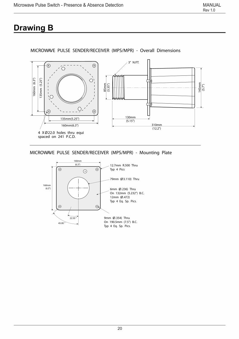
MICROWAVE PULSE SENDER/RECEIVER (MPS/MPR) - Mounting Plate
MICROWAVE PULSE SENDER/RECEIVER (MPS/MPR) - Overall Dimensions
160mm(6.3")
22.50
160mm(6.3")
45.00
9mm (Ø.354) ThruOn 190.5mm (7.5") B.C.Typ 4 Eq. Sp. Pics.
6mm (Ø.236) ThruOn 132mm (5.232") B.C.12mm (Ø.472)Typ 4 Eq. Sp. Pics.
79mm (Ø3.110) Thru
12.7mm R.500 ThruTyp 4 Pics
160mm(6.3")
160m
m(6
.3")
310mm(12.2")
3" N.P.T.
85m
m(3
.35"
)
130mm(5.15")
145m
m(5
.7")
4 X Ø22.0 holes thru equispaced on 241 P.C.D.
135m
m(5
.25"
)
135mm(5.25")
Drawing B

Microwave Series21
Sultan 234 Series
Microwave Pulse Switch - Presence & Absence Detection MANUAL Rev 1.0
Dimensions
Remote Microwave Doppler System - Remote Amplier (MDA)
160mm (6.3")14
5mm
(5.7
")
170mm (6.8")
4 x 5.0mm holes
137m
m(5
.4")
61.5
mm
(5.4
")25
.5m
m(1
")
61.5mm (5.4") 25.5mm (1")
61.5
mm
(5.4
")25
.5m
m(1
")
25.5mm (1") 61.5mm (5.4")
Integral Microwave Doppler System (MDI)
310mm(12.2")
3" N.P.T.
85m
m(3
.35"
)
130mm(5.15")
145m
m(5
.7")
160mm(6.3")
160m
m(6
.3")
4 X Ø22.0 holes thru equispaced on 241 P.C.D.
135m
m(5
.25"
)
135mm(5.25")
Remote Microwave Doppler System - Remote Sensor (MDR)
135mm (5.25")
135m
m(5
.25"
)
160m
m(6
.3")
UHMWWindow
1" BSP nipple
Polyester coated mild steel pipe
130mm (5")
192mm (7.6")
3" N.P.T.
Drawing C

Microwave Pulse Switch - Presence & Absence Detection MANUAL Rev 1.0
22
Drawing D
3" & 4" Weldment Window
3" & 4" UHMW Polyethylene/Ceramic Window
3" & 4" Teon/Ceramics Window
147.6mm(Ø5.81)
120.
7mm
(4.7
5")
4" N.P.T.
5.1mm(0.20")
5.1mm(0.20")
83.7
mm
(3.3
0")
5.1mm(0.20")
3" N.P.T.
5.1mm(0.20")
25.4mm(1.0")
3" N.P.T.
10.2mm (0.40")
Ø.312 Typ2 Pics
56.2mm (2.21")
Ø.312 Typ2 Pics
56.2mm (2.21")
25.4mm(1.0")
3" N.P.T.
10.2mm (0.40")25.4mm(1.0")
4" N.P.T.
10.2mm (0.40")
25.4mm(1.0")
4" N.P.T.
10.2mm (0.40")

Microwave Series23
Sultan 234 Series
Microwave Pulse Switch - Presence & Absence Detection MANUAL Rev 1.0
Drawing E
Ceramic Heat Shield Mount
Ceramic Brick
Ceramic Brick Mount Assembly
152.4mm (6.0")
317.5mm (12.5")
152.4mm (6.0")
101.6mm(4.0")

Microwave Pulse Switch - Presence & Absence Detection MANUAL Rev 1.0
24
76.2mm(3.0")
Assembly View; Firebrick Mount
419.1mm (16.5")
228.6mm (9.0")
50.8mm(2.0")
215.9mm(8.5")
114.3mm(4.5")
Isometric View; Firebrick Mount
Firebrick; Firebrick Mount
152.4mm (6.0")
114.3mm(4.5")
Drawing F

Microwave Series25
Sultan 234 Series
Microwave Pulse Switch - Presence & Absence Detection MANUAL Rev 1.0
Waveguide WR90 Cone
Waveguide WR90 Straight
Waveguide WR90 Bend
Note: "A" = Per ApplicationFinish Per Application
32mm(1.275")
33mm(1.283")
23mm(0.890")
10mm(0.90")
41mm(1.625")
41mm(1.625")
33mm (1.283")
33mm(1.283")
4mm (Ø.172) ThruTyp 4 Pics
FB
GTAW
"A"
Note: "A" = Per ApplicationFinish Per Application
FB
FBGTAW
"A"
33mm(1.283")
4mm (Ø.172) ThruType 8 Pics 33mm (1.283")
Drawing G

Microwave Pulse Switch - Presence & Absence Detection MANUAL Rev 1.0
26
DRAWING H
DRAWING I
Glass Window
19.9mm (0.78")6.3mm (0.25")
Adjustable Microwave Bracket
2" N.P.T.
135mm (5.3") (Ø.400) Thru
116mm (4.6")
147mm (5.8")
336mm (13.2")
225mm(8.9")
Drawing H, I

Microwave Series27
Sultan 234 Series
Microwave Pulse Switch - Presence & Absence Detection MANUAL Rev 1.0
Sequencer
The Microwave Pulse Sequencer is powered by mains or 24Vdc, it is a self-contained unit which synchronises the pulsing of up to 6 microwave units. Each unit is allocated a unique ‘time slot’ in sequence, in which that unit may transmit (and receive). This means that no 2 units will be operating at once, eliminating the possibility of interfer-ence between units.
Installation involves connecting a pair of wires from the sequencer to the U&V terminals on each MRA. No inter-nal modification of the MRA is required.
A green flashing LED indicates that: (a) the sequencer is powered and;(b) that its oscillator is running
Sequencer - Installation
Specifications
Power: 110-120 or 220-240Vac 50 or 60 Hz or 24VdcOutputs: Active-low with internal 470Ω pull-up to +5vOutput pulse width: 341.3 µSTime between pulses: 5.46mSInternal Timebase: Quartz Crystal
MICROWAVE PULSE SEQUENCER – MSEQ
Connection Sequenced Outputs: 1-6 to V Terminal — Ground to U Terminal
MRA
U V W
GNDBLACK(Screen)
BLUE
RED
P E S T
TO MRS(SENDER)
TO MRR(RECEIVER)
FUSE
MSEQMICROWAVE PULSER SEQUENCER
A N E 1 2 3 4 5 6
POWER240VacOR
24Vdc
To otherMRA UNITSas required
FUSE
Top Row = GNDBottom RowSEQUENCEDOUTPUTS
Green LED: Power ONRed LED: PULSE
+24VOV
USE TWISTED PAIRSCREENING OPTIONAL
GROUND
USE TWISTEDPAIRS
Installation

Microwave Pulse Switch - Presence & Absence Detection MANUAL Rev 1.0
28
Troubleshooting
System Inoperative
Yes
SystemInoperative/Either
MPS or MPR or Both
IsPower Applied to
Both Units
Check Voltage andApply PowerTo Both Units
No
No
No
No
IsLD1 Lit Greenon both units
Line ofSight Clear Between
MPS & MPR?
Is LD2on MPR Lit Red?
Proceed to VerifyRelayOperation Consult Factory
IsAlignment ofMPS & MPR
Correct
Clear Line ofSight Between
MPS & MPR
Check Input Voltageand Fuses/ReplaceFuses if Necessary
Correct Alignment sothat the conduit entryholes on the MPS &
MPR are at thesame angle
No
Yes
Yes
Yes
Yes
If the fuses continue to blowafter replacement, consultthe factory

Microwave Series29
Sultan 234 Series
Microwave Pulse Switch - Presence & Absence Detection MANUAL Rev 1.0
Troubleshooting (con’t)
With LD2 a steady red,toggle SW1 on
MPR unit.
Does LD3on MPR unit toggle
on/o/on...?No
NoDoes
LD3 toggleon/o/on...?
Proceed toSensitivity Adjustments
Return SW1on MPR to original
Position.
Yes
Yes
Consult Factory
Consult Factory
Have someone depressthe TEST buttonseveral times on
the MPS unit While youmonitor LD3

Microwave Pulse Switch - Presence & Absence Detection MANUAL Rev 1.0
30
Troubleshooting (con’t)
Sensitivity Adjustments
Process Active?
Sensitivity Adjustmentsmust be made with anactive process. Ensure
that the process isactive!
Yes
No
False Tripor
No Trip
Proceed toNo Trip Adjustments
page 22
Proceed toFalse Trip Adjustments
page 22
If the setup procedure inthis manual was notfollowed during installation,it will be necessary tocomplete it now.
START

Microwave Series31
Sultan 234 Series
Microwave Pulse Switch - Presence & Absence Detection MANUAL Rev 1.0
Troubleshooting (con’t)
LD2Still Intermittent?
Adjust ReceiverSensitivity
Yes
No
START
False Trip Adjustment
LD2Steady or FlashingLD2 Signal Indication is
intermittentLD2 Signal Indicator
Steady
Decrease ReceiverSensitivity
Increase RelayTime Delay
Return to NormalOperations
Return to NormalOperations
Return to NormalOperations

Microwave Pulse Switch - Presence & Absence Detection MANUAL Rev 1.0
32
Troubleshooting (con’t)
Yes
NoIs Product in Path?
Product must be inpath for signal to be
attenuated and correctadjustment
Adjust RelayTime Delay
Return to NormalOperations
No Trip Adjustment
Yes
NoLD2
Signal Present?
AdjustReceiver Sensitivity
START

Microwave Series33
Sultan 234 Series
Microwave Pulse Switch - Presence & Absence Detection MANUAL Rev 1.0
Safety Information
FCC REGULATIONS:
Qualifications -
The Federal Communications Commission imposes strict requirements on radiating sources such as the MPS/MPR, MRS/MRR/MRA,MRS-H/MRR-H/MRA Microwave Pulse Systems. This unit is tested to, and meets these requirements, which include operating fre-quency and stability, harmonic and spuriousgenerations and power output. The Hawk Microwave Pulse System complies with FCC Rules Part 15 for industrial controls. No licenses or approvals are required to use the system.
Requirements -(A) OSHA - 10mW/cm2of radiated power.(B) ANSI - 5mW/cm2 of radiated power.
The Hawk MPS/MPR, MRS/MRR/MRA, MRS-H/MRR-H/MRA Microwave Pulse Systems have 20µW/cm2 of radiated power.
Note: The Hawk MPS/MPR, MRS/MRR/MRA,MRS-H/MRR-H/MRA Microwave Pulse Systemsare well be-low the stringent safety standards required by both the above governing bodies. It is regarded as a totally SAFE level control and may be used with no special precau-tions.
Warranty
Hawk control products will be replaced, put in good op-erating condition, or the purchase price refunded, at the option of Hawk, free of charges except transportation, if defective in their manufacture, labeling, packaging ,or shipping, and if notice of said defect is received by Hawk with in one year from the date of shipment.
The cost of such replacement, repair or refund or price shall be the exclusive remedy for any breach of warranty, and Hawk shall not be liable to any person for conse-quential damages for injury or commercial loss resulting from any breach of any warranty particular purpose, and makes no other warranty, express or implied, including implied warranty arising from course of dealing or usage of trade.

Microwave Pulse Switch - Presence & Absence Detection MANUAL Rev 1.0
34
Part Numbering
RMS & IMS MICROWAVE UNIT Model RMS Remote Microwave set with sender, Receiver and Amplifier without 3” weldment MRS Remote Microwave Sender without 3” weldment. MRR Remote Microwave Receiver without 3” weldment. MRA Remote Microwave Amplifier RMSH High Power Remote Microwave set with sender, Receiver and Amplifier without weldment MRSH High Power Remote Sender without weldment MRRH High Power Remote Receiver without weldment MRAH High Power Remote Microwave Amplifier MRR3 Remote Microwave Receiver with Signal Recognition Stability IMS Integral Microwave System with Sender and receiver without 3” Weldemnt MPS Integral Microwave Sender without 3” Weldemnt MPR Integral Microwave Receiver without 3” Weldemnt MPR3 Integral Microwave Receiver with Signal Recognition Stability MSEQ Microwave Sequencer Unit Power Supply 240 240 Vac Volt 220 220 Vac Volt 115 115 Vac Volt 48 48 Vdc Volt Outputs 0 Standard relay Output 6 Solid State Relay Output Facing Material 0 UHMW Polyethylene 1 PTFE Teflon for complete set pair 2 PTFE Teflon for sender or receiver, each W1 Wave guide connector for set pair W2 Wave guide connector for sender or receiver, each Z Special request
ATEX Approvals X not required A22 ATEX Zone 22 A22 ATEX Zone 22 for a complete set
Cable length 10 10m cable (Standard) 30 30m cable for MRS, MRR, MRSH, MRRH 30S 30m cable for RMS 50 50m cable for MRS, MRR, MRSH, MRRH 50S 50m cable for RMS X Not required
RMS 240 0 0 X 10
Part Numbering

Microwave Series35
Sultan 234 Series
Microwave Pulse Switch - Presence & Absence Detection MANUAL Rev 1.0
Mounting Accessories MA 0 3” Weldment each 1 2” Glass window each 3 3” UHMW Windows & Weldment each 4 4” UHMW Windows & Weldment each 5 6” UHMW Windows & Weldment each 6 3” PTFE Windows & Weldment each 7 4” PTFE Windows & Weldment each 8 6” PTFE Windows & Weldment each 9 9’ x 4,5” Fire brick each 10 6” x 4” ceramic brick each 11 Shock insulation mounts pack of 4 12 Adjustable mounting UHMW windows each 13 Adjustable mounting PTFE windows each 14 Remote wave guide Assembly 15 Mounting Flange pipe 16 3” Ceramic window & weldment each 17 4” Ceramic window & 4” weldment each 18 4” Microwave Weldment only each 19 3” Stainless steel Weldment only for UHMW each 20 4” UHMW Windows only each 21 3” UHMW Windows only each 22 4” Stainless steel Weldment only for UHMW each MA 0
Full Part Number
Electronics + Mounting Accessories
RMS 240 0 0 X 10 + MA 0
Part Numbering
Hawk Measurement Systems15-17 Maurice CrtNunawading VIC 3131AustraliaPhone: +61 3 9873 4750Fax: +61 3 9873 [email protected]
Hawk Measurement America3911 W. Van Burren STE B-7Phoenix, Arizona 85009USAPhone: +1 888 HAWKLEVEL (1 888 429 5538)Fax: +1 602 353 [email protected]
Contact
![IEEE TRANSACTIONS ON MICROWAVE THEORY AND …...gyro-traveling wave amplifier and microwave pulse compressor. ... (BWOs) and traveling wave tubes (TWTs)[1], and magnetrons ... theory](https://static.fdocuments.us/doc/165x107/60fa9241534b8a2a11167629/ieee-transactions-on-microwave-theory-and-gyro-traveling-wave-ampliier-and.jpg)