Manual LDU3000/3000A
20
Manual LDU3000/3000A Version-E121024
Transcript of Manual LDU3000/3000A

Manual LDU3000/3000A
Version-E121024

Manual LDU3000/3000A
Page 2
Important Information General Before using your ALGE-TIMING device read the complete manual carefully. It is part of the device and contains important information about installation, safety and its intended use. This manual cannot cov-er all conceivable applications. For further information or in case of problems that are mentioned not at all or not sufficiently detailed, please contact your ALGE-TIMING representative. You can find contact details on our homepage www.alge-timing.com Safety Apart from the information of this manual all general safety and accident prevention regulations of the legislator must be taken into account. The device must only be used by trained persons. The setting-up and installation must only be exe-cuted according to the manufacturer’s data. Intended Use The device must only be used for its intended applications. Technical modifications and any misuse are prohibited because of the risks involved! ALGE-TIMING is not liable for damages that are caused by improper use or incorrect operation. Power supply The stated voltage on the type plate must correspond to voltage of the power source. Check all con-nections and plugs before usage. Damaged connection wires must be replaced immediately by an au-thorized electrician. The device must only be connected to an electric supply that has been installed by an electrician according to IEC 60364-1. Never touch the mains plug with wet hands! Never touch live parts! Cleaning Please clean the outside of the device only with a smooth cloth. Detergents can cause damage. Never submerge in water, never open or clean with wet cloth. The cleaning must not be carried out by hose or high-pressure (risk of short circuits or other damage). Liability Limitations All technical information, data and information for installation and operation correspond to the latest status at time of printing and are made in all conscience considering our past experience and knowledge. Information, pictures and description do not entitle to base any claims. The manufacturer is not liable for damage due to failure to observe the manual, improper use, incorrect repairs, technical modifications, use of unauthorized spare parts. Translations are made in all conscience. We assume no liability for translation mistakes, even if the translation is carried out by us or on our behalf. Disposal If a label is placed on the device showing a crossed out dustbin on wheels (see drawing), the European directive 2002/96/EG applies for this device. Please get informed about the applicable regulations for separate collection of electrical and electronical waste in your country and do not dispose of the old devices as household waste. Correct disposal of old equipment protects the environment and humans against negative con-consequences! Copyright by ALGE-TIMING GmbH All rights reserved. Any duplication, either in full or in part, requires the prior written consent of the copyright holder.

Manual LDU3000/3000A
Page 3
Table of Contents 1 Chapter I: Functions and Installation of LDU3000(A). .............................................. 4 1.1 Functions of LDU3000(A) ..................................................................................... 4 1.2 Installation of LDU3000A ...................................................................................... 6
2 Chapter II: Wiring and Application of LDU3000(A) .................................................... 7 2.1 Signal Diagram of IMPOSA Screen system .......................................................... 7 2.2 LDU3000/LDU300A- Connection to LED Screen .................................................. 8 2.3 LDU3000/LDU3000A-Connection to Light Sensor .............................................. 10 2.4 LDU3000/A-Connection and Communication to Computer ................................. 11 2.4.1 RS232 ............................................................................................................................................ 11 2.4.2 Communication via RS485 ............................................................................................................ 13 2.4.3 Communication via Ethernet .......................................................................................................... 13 2.5 Connection VPU3000 and LDU3000 via Optical Fiber ........................................ 13
3 Chapter III: Maintenance of LDU3000(A) .................................................................. 14 3.1 Backup LDU3000 to Computer ........................................................................... 14 3.2 Restoration and Maintenance ............................................................................. 14 3.2.1 Replacement of LDU3000.............................................................................................................. 14 3.2.2 Replacement of Optical Fiber and Optical Fiber Plug .................................................................... 14
4 Explanation for QS5003 in LDU3000HUB ................................................................ 18 4.1 Layout of QS5003 ............................................................................................... 18 4.1.1 Functions of Interfaces .................................................................................................................. 18 4.1.2 2.3 Functions of Dip Switch SW1 ................................................................................................... 18 4.2 Devices and Parts ............................................................................................... 19
Brief Introduction This document covers three chapters:
Chapter I: Functions and Installation LDU3000(A)
Chapter II: Connection and Application LDU3000(A) (offline and synchronous connections)
Chapter III: Maintenance LDU3000(A) (backup, maintenance, functions of control boards)

Manual LDU3000/3000A
Page 4
1 Chapter I: Functions and Installation of LDU3000(A).
1.1 Functions of LDU3000(A) LDU3000: for indoor applications and fast installation of moveable LED screens, e.g., IM-POSA Kwik system.
483
396
68.5
250
283253
65
LDU3000RUN
POWER
435

Manual LDU3000/3000A
Page 5
LDU3000A:For outdoor use, with IP level of 54.
fig.1
350
450
120
LDU3000A
fig. 2
Functions • With a maximum of 16 signal outputs • Can be connected to VPU3000 to form a synchronous playing system • Can be used alone as an offline system; can control maximum resolution of 1024X768 • Communications: Fiber Optic (for synchronous system), Ethernet (Offline), RS232 (for
updating), RS485 • Can be connected to Light Sensor and examine the real-time ambient brightness, in or-
der to adjust the brightness of screen automatically.

Manual LDU3000/3000A
Page 6
1.2 Installation of LDU3000A LDU3000A is waterproof and suitable for outdoor installation. It can be installed on the mid-dle of the right side of LED screen (rear view). LDU3000A can be fixed to frameworks with the below dimension:
LDU3000A
496
290
34
128
350
450
Fig.3
LDU3000A
396
390
42
350
450
128
Fig.4

Manual LDU3000/3000A
Page 7
2 Chapter II: Wiring and Application of LDU3000(A)
2.1 Signal Diagram of IMPOSA Screen system
5002
CON2CON3
JP7
SW
1S
W2
J1
J2
J3
J4
J5
J6
JP2
JP4
JP12
5002
CON2CON3
JP7
SW
1S
W2
J1
J2
J3
J4
J5
J6
JP2
JP4
JP12
TX+ RTX- B
RS+ G RS- Y
5002
CON2CON3
JP7
SW
1S
W2
J1
J2
J3
J4
J5
J6
JP2
JP4
JP12
TX+ RTX- B
RS+ G RS- Y
TX+ RTX- B
RS+ G RS- Y
5002
CON2CON3
JP7
SW
1S
W2
J1
J2
J3
J4
J5
J6
JP2
JP4
JP12
5002
CON2CON3
JP7
SW
1S
W2
J1
J2
J3
J4
J5
J6
JP2
JP4
JP12
TX+ RTX- B
RS+ G RS- Y
5002
CON2CON3
JP7
SW
1S
W2
J1
J2
J3
J4
J5
J6
JP2
JP4
JP12
TX+ RTX- B
RS+ G RS- Y
TX+ RTX- B
RS+ G RS- Y
5002
CON2CON3
JP7
SW
1S
W2
J1
J2
J3
J4
J5
J6
JP2
JP4
JP12
5002
CON2CON3
JP7
SW
1S
W2
J1
J2
J3
J4
J5
J6
JP2
JP4
JP12
TX+ RTX- B
RS+ G RS- Y
5002
CON2CON3
JP7
SW
1S
W2
J1
J2
J3
J4
J5
J6
JP2
JP4
JP12
TX+ RTX- B
RS+ G RS- Y
TX+ RTX- B
RS+ G RS- Y
A1-1A1-2A1-m
A2-1A2-2A2-m
An-1An-2An-m
Rear View
CON2 CON2 CON2CON3CON3CON3
CON2 CON2 CON2CON3CON3CON3
CON2 CON2 CON2CON3CON3CON3
TX+ RTX- B
RS+ G RS- Y
CON2
LDU3000A HUB BOX
TX+ RTX- B
RS+ G RS- Y
CON2
TX+ RTX- B
RS+ G RS- Y
CON2
GND
RS485
RS232
OPEN
MODECOM1SEL
TABLE OF SEL
LUM SENSOR
VCC
VCC
LUM
LUM
RS-
RS+
SEL
GND
GND D-
D+
RXD2
RXD1
TXD1
TXD2
LINK
ACTGNDCL
CH
+5V
P13
P12
P11
P10
P9
P8
P7
P6
P5
P4
P3
P2
P1
SENSOR COM2 COM1
CON5
CON7CON1
QS5003
CON9CON8
SW1
P14
P15
P16 DC 5V
P1
P2
Pn
P1P2
DVI OUT DVI IN
VGA INUSB
RS232Video S-Video
Fiber optic
VPU 3000PC
AC INPUT 84~260V USB
DVI DVI VGA
RS232
CVBS 1
S_VIDEOPb
YPr
CVBS 2
CVBS 3CVBS 4
INPUT
DVI
OUTPUT3 25
RXDGND TXD
VGA Synchronous
PC
RS232
Enthernet
OFFLINE
Fig.5

Manual LDU3000/3000A
Page 8
2.2 LDU3000/LDU300A- Connection to LED Screen 1) When LDU3000 HUB box is connected to screen, the cabinet on top/bottom of the first row from right of the screen (back view) should be connected to Port No.1 in LDU3000; the cabinet of the second row should be connected to Port No.2 in LDU3000 and so on.
1 3 5 7 9 11 13 15
161412108642
RS485D- D+
CHANNEL TX RX
ETHERNET
SENSOR
AC
INPU
T 8
4~26
0V
5002
CON2CON3
JP7
SW
1S
W2
J1
J2
J3
J4
J5
J6
JP2
JP4
JP12
5002
CON2CON3
JP7
SW
1S
W2
J1
J2
J3
J4
J5
J6
JP2
JP4
JP12
5002
CON2CON3
JP7
SW
1S
W2
J1
J2
J3
J4
J5
J6
JP2
JP4
JP12
A1-1A1-2A1-m
CON3CON3CON3
TX+ RTX- B
RS+ G RS- Y
CON2
TX+ RTX- B
RS+ G RS- Y
CON2
TX+ RTX- B
RS+ G RS- Y
CON2
1
2
n
Rear View
LDU3000 HUB箱
Fig.6

Manual LDU3000/3000A
Page 9
2)When LDU3000A HUB box is connected to screen, the cabinet on the right of the first line of the screen (back view) should be connected to output Port No.1 in mainboard QS5003 in-sided the LDU3000A; the cabinet of the second line should be connected to output Port No.2 in mainboard QS5003 and so on.
5002
CON2CON3
JP7
SW1
SW2
J1
J2
J3
J4
J5
J6
JP2
JP4
JP12
5002
CON2CON3
JP7
SW1
SW2
J1
J2
J3
J4
J5
J6
JP2
JP4
JP12
5002
CON2CON3
JP7
SW1
SW2
J1
J2
J3
J4
J5
J6
JP2
JP4
JP12
A1-1
A2-1
An-1
CON3
CON3
CON3
TX+ RTX- B
RS+ G RS- Y
CON2
LDU3000A HUB箱
TX+ RTX- B
RS+ G RS- Y
CON2
TX+ RTX- B
RS+ G RS- Y
CON2
GND
RS485
RS232
OPEN
MODECOM1SEL
TABLE OF SEL
LUM SENSOR
VCC
VCC
LUM
LUM
RS-
RS+
SEL
GND
GND
D-D+RXD2
RXD1
TXD1
TXD2
LINK
ACTGND
CLCH+5V
P13P12
P11P10
P9P8
P7P6
P5P4
P3P2
P1
SENSOR COM2 COM1
CON5
CON7CON1
QS5003
CON9CON8
SW1
P14P15
P16 DC 5V
P1
P2
Pn
Rear View
Fig.7 Note: for more about QS5003, please refer to the appendix.

Manual LDU3000/3000A
Page 10
2.3 LDU3000/LDU3000A-Connection to Light Sensor 1) Light Sensor
Fig.8 2) LDU3000 Connect the provided Light Sensor directly to the sensor interface at the back of LDU3000, see the picture below:
CHANNEL 2TX RX
CHANNEL 1TX RX
CH2CH1
Fig.9 3) LUD3000A Connect the provided Light Sensor directly to the sensor CON interface on mainboard QS5003 of LDU3000A, see the picture below:
LDU3000A HUB Box
GND
RS485
RS232
OPEN
MODECOM1SEL
TABLE OF SEL
LUM SENSOR
VCC
VCC
LUM
LUM
RS-
RS+
SEL
GND
GND D-
D+
RXD2
RXD1
TXD1
TXD2
LINK
ACT
GNDCL
CH
+5V
P13
P12
P11
P10
P9
P8
P7
P6
P5
P4
P3
P2
P1
SENSOR COM2 COM1
CON5
CON7CON1
QS5003
CON9CON8
SW1
P14
P15
P16 DC 5V
Fig.10

Manual LDU3000/3000A
Page 11
2.4 LDU3000/A-Connection and Communication to Computer
GND
RS485
RS232
OPEN
MODECOM1SEL
TABLE OF SEL
LUM SENSOR
VC
CV
CC
LUM
LUM
RS
-
RS
+
SE
L
GN
D
GN
D
D-
D+
RX
D2
RX
D1
TXD
1
TXD
2
LIN
K
AC
T
GN
D
CL
CH
+5V
P13P12
P11P10
P9P8
P7P6
P5P4
P3P2
P1
SENSOR COM2 COM1
CON5
CON7 CON1
QS5003
CON9CON8
SW1
P14P15
P16 DC 5V
Fig.11
There are two independent COM interfaces in mainboard QS5003 of LDU3000(A)
• COM1: RS232 or RS485; If SEL (connecting to GND) is selected, the communication should be RS232; If SEL is suspended, the communication be RS485; RS232 and RS485 cannot be used together.
• COM2: RS232 There is one Ethernet interface in mainboard QS5003 of LDU3000/A.
• CON1: Ethernet interface For more about QS5003, please refer to the explanation below.
2.4.1 RS232 1) Where the system is offline, RS232 cable may be used to communicate with QS5003 to change screen content or settings. 2 )W here it is V QS5003. Note: No matter if it is an offline or a synchronous system, the communication of RS232 must be considered while doing the wiring. Because RS232 is short in commu-nication distance, RS232 interface should be prepared at the bottom of screen (or bot-tom of supporting columns) while doing the wiring, in order that personnel can con-nect the screen to laptop.

Manual LDU3000/3000A
Page 12
3) Connection of RS232 COM1:
GND
RS485
RS232
OPEN
MODECOM1SEL
TABLE OF SEL
LUM SENSOR
VCC
VCC
LUM
LUM
RS-
RS
+
SEL
GN
D
GN
D
D-
D+
RXD
2
RXD
1
TXD
1
TXD
2
LIN
K
AC
T
GN
D
CL
CH
+5V
P13
P12
P11
P10
P9
P8
P7
P6
P5
P4
P3
P2
P1
SENSOR COM2 COM1
CON5
CON7 CON1
QS5003
CON9CON8
SW1
P14
P15
P16 DC 5V
GN
DR
XD
1
TXD
1Fig.12
COM2:
GND
RS485
RS232
OPEN
MODECOM1SEL
TABLE OF SEL
LUM SENSOR
VC
CV
CC
LUM
LUM
RS-
RS+
SE
L
GN
D
GN
D
D-
D+
RX
D2
RX
D1
TXD
1
TXD
2
LIN
K
AC
T
GN
D
CL
CH
+5V
P13
P12
P11
P10
P9P8
P7P6
P5P4
P3P2
P1
SENSOR COM2 COM1
CON5
CON7 CON1
QS5003
CON9CON8
SW1
P14
P15
P16 DC 5V
GN
DR
XD
2
TXD
2
Fig.13

Manual LDU3000/3000A
Page 13
2.4.2 Communication via RS485
GND
RS485
RS232
OPEN
MODECOM1SEL
TABLE OF SEL
LUM SENSOR
VC
CV
CC
LUM
LUM
RS-
RS
+
SE
L
GN
D
GN
D
D-
D+
RX
D2
RX
D1
TXD
1
TXD
2
LIN
K
AC
T
GN
D
CL
CH
+5V
P13
P12
P11
P10
P9
P8
P7
P6
P5
P4
P3
P2
P1
SENSOR COM2 COM1
CON5
CON7 CON1
QS5003
CON9CON8
SW1
P14
P15
P16 DC 5V
RS
-R
S+
Fig.14 2.4.3 Communication via Ethernet Where the system is offline, Ethernet cable may be used to connect mainboard QS5003 of LDU3000A to COM1 interface.
2.5 Connection VPU3000 and LDU3000 via Optical Fiber There two optical fiber interfaces in LDU, with one for data transmission, the other for hot backup.
Fiber optic
1 3 5 7 9 11 13 15
161412108642
RS485D- D+
CHANNEL TX RX
ETHERNET
SENSOR
AC
INP
UT
84~
260V
LDU 3000
VPU 3000
AC INPUT 84~260V USB
DVI DVI VGA
RS232
CVBS 1
S_VIDEOPb
YPr
CVBS 2
CVBS 3CVBS 4
INPUT
DVI
OUTPUT3 25
RXDGND TXD
Fig.15 In order not to affect the screen door from opening and closing, the wire and cables must fol-low along the suction canals at the bottom of cabinets, see the picture below:

Manual LDU3000/3000A
Page 14
3 Chapter III: Maintenance of LDU3000(A)
3.1 Backup LDU3000 to Computer IMPOSA Tools program should be used. For operation details, please refer to User’s Manual of IMPOSA Tools. Then you can save the LDU information to computer. 1. Select Tool\Backup LDU date\Save to computer 2. Select a location for saving backup file and name the file to be saved. 3. Press “Backup” button to start backing up and wait until it stops.
3.2 Restoration and Maintenance 3.2.1 Replacement of LDU3000
• Replace the mainboard inside LDU. Change for a new LDU mainboard, and connect it to power supply, communication cables and optic fiber. Do make sure that all con-nections are the same as before.
• Configure Parameters. Open IMPOSA Tools and select Tool\Recover\Recover from computer, and confirm the prompting message, open the LDU backup file from your computer, for example, backup.LDU.
• Press Restore to start backing up and then wait until it ends. You can follow the same operations to update all the LDU(s) (if there are many LDUs).
• Switch off and restart the power supply of LDU. • Check if the screen can work normally.
3.2.2 Replacement of Optical Fiber and Optical Fiber Plug Optical Fiber should be multimode.
• For outdoor use, the optical fiber is usually fusion spliced by expertise on-site and does not need to change.
• For indoor use, optical fiber is usually grafted in the optical fiber connector. So you need to be careful when inserting or unplugging the optical fiber head, not to damage it.
• Please take the following steps to unplug the optical fiber:
Step 1

Manual LDU3000/3000A
Page 15
Step 2
Step 3
Step 4

Manual LDU3000/3000A
Page 16
Step 5
Step 6 Please take the following steps to insert the optical fiber.
Step 1

Manual LDU3000/3000A
Page 17
Step 2
Step 3

Manual LDU3000/3000A
Page 18
Appendix 4 Explanation for QS5003 in LDU3000HUB
4.1 Layout of QS5003
4.1.1 Functions of Interfaces P1-P16: Data output interfaces, respectively connected to input of the first cabinet for each line of the screen. Counted from top to bottom, the number is P1, P2, and P3… … COM1: RS232 or RS485; If SEL (connecting to GND) is selected, the communication should be RS232; if SEL is suspended, it should be RS485. COM2: RS232 COM7: Sensor CAN bus interface for light sensor, temperature sensor, humidity sensor.
4.1.2 2.3 Functions of Dip Switch SW1 DIP1~DIP4=AD (4 ….0) Address Range :0~ 7 Note: “0” means ON, “1” means OFF.
Optical Interface Dip Switch SW1
Ethernet Signal Output Port Port for light sen-sor
Port for Tempe-rature and Humidity
COM2 port COM1port Power Input
Data Port
Manual LDU3000/3000A
Page 19
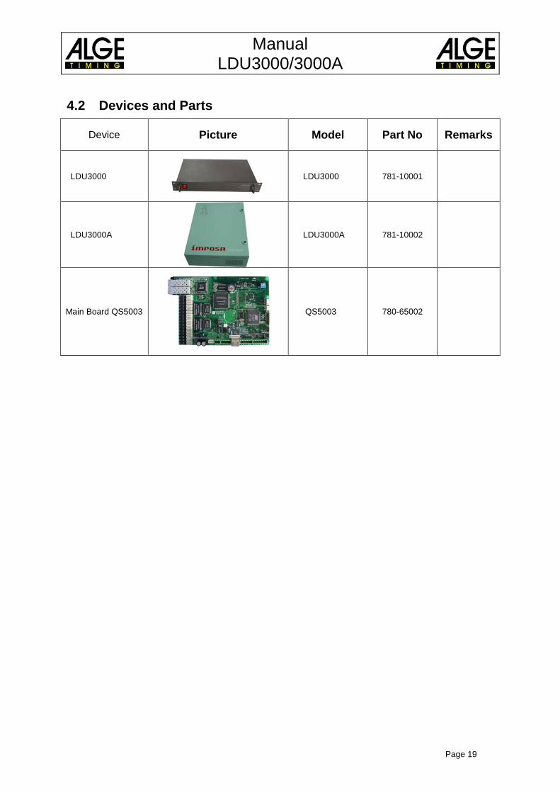
4.2 Devices and Parts
Device Picture Model Part No Remarks
LDU3000
LDU3000 781-10001
LDU3000A
LDU3000A 781-10002
Main Board QS5003
QS5003 780-65002

Manual LDU3000/3000A
Page 20
Subject to changes
Copyright by
ALGE-TIMING GmbH Rotkreuzstr. 39
6890 Lustenau / Austria www.alge-timing.com