Manual G450 with Track Changes VER102407 - … / ISA-12.13.01-2000. 6 Design Hook for carrying strap...
44
Operation and Maintenance Manual G450 Operation Manual Worldwide Manufacturer of Gas Detection Solutions
Transcript of Manual G450 with Track Changes VER102407 - … / ISA-12.13.01-2000. 6 Design Hook for carrying strap...

Operation and Maintenance Manual
G450Operation Manual
Worldwide Manufacturer of Gas Detection Solutions


GfG Products for Increased Safety
Congratulations on your purchase of a high technology product from GfG – you have made an excellent choice!
Our detectors are characterized by reliability, safety, peak performance and economic efficiency. They comply with national and international directives.
This manual will help you operate the detector quickly and safely.
Please take note of these instructions before putting the device into operation!
If you have any questions, please feel free to contact us.
GfG Instrumentation, Inc. 1194 Oak Valley Drive, Ste 20 Ann Arbor, MI 48108 USA
Phone: (800) 959-0329 or (734) 769-0573 Fax: (734) 769-1888 E-mail: [email protected] Website: www.gfg-inc.com
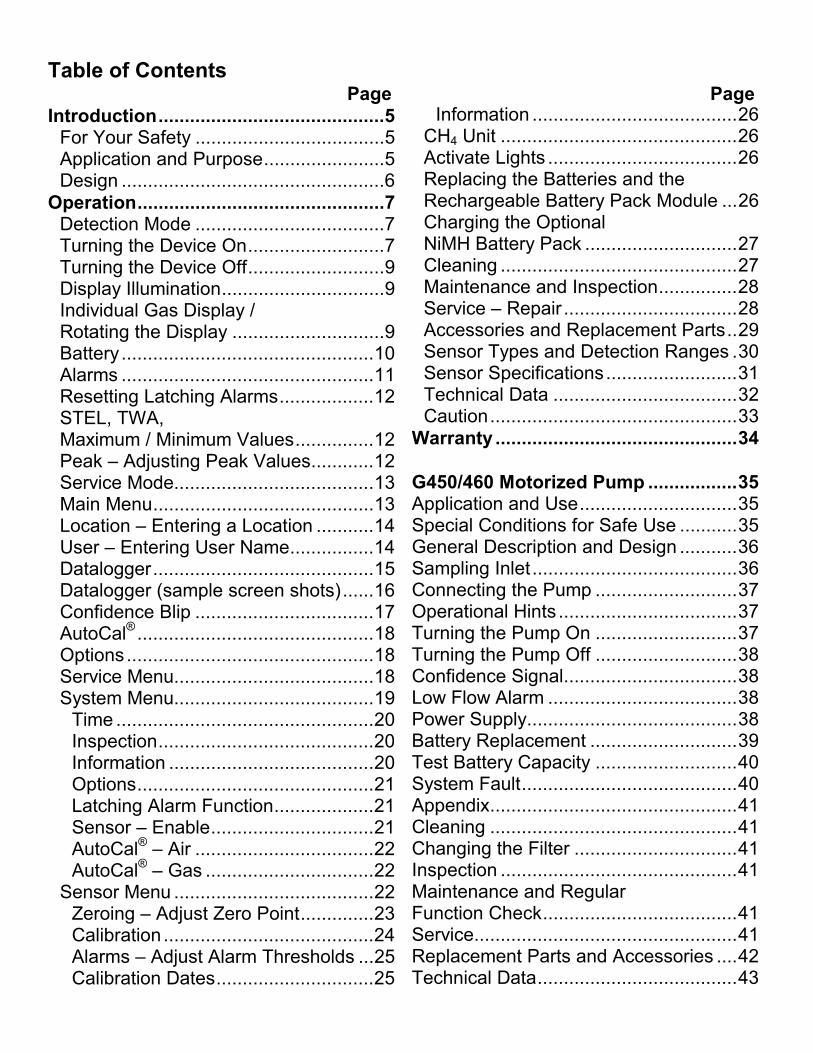
Table of Contents Page Page Introduction...........................................5
For Your Safety ....................................5 Application and Purpose.......................5 Design ..................................................6
Operation...............................................7 Detection Mode ....................................7 Turning the Device On..........................7 Turning the Device Off..........................9 Display Illumination...............................9 Individual Gas Display / Rotating the Display .............................9 Battery................................................10 Alarms ................................................11 Resetting Latching Alarms..................12 STEL, TWA, Maximum / Minimum Values...............12 Peak – Adjusting Peak Values............12 Service Mode......................................13 Main Menu..........................................13 Location – Entering a Location ...........14 User – Entering User Name................14 Datalogger..........................................15 Datalogger (sample screen shots)......16 Confidence Blip ..................................17 AutoCal®.............................................18 Options...............................................18 Service Menu......................................18 System Menu......................................19
Time .................................................20 Inspection.........................................20 Information .......................................20 Options.............................................21 Latching Alarm Function...................21 Sensor – Enable...............................21 AutoCal® – Air ..................................22 AutoCal® – Gas ................................22
Sensor Menu ......................................22 Zeroing – Adjust Zero Point..............23 Calibration ........................................24 Alarms – Adjust Alarm Thresholds ...25 Calibration Dates..............................25
Information .......................................26 CH4 Unit .............................................26 Activate Lights ....................................26 Replacing the Batteries and the Rechargeable Battery Pack Module ...26 Charging the Optional NiMH Battery Pack .............................27 Cleaning .............................................27 Maintenance and Inspection...............28 Service – Repair .................................28 Accessories and Replacement Parts..29 Sensor Types and Detection Ranges .30 Sensor Specifications.........................31 Technical Data ...................................32 Caution...............................................33
Warranty ..............................................34 G450/460 Motorized Pump .................35 Application and Use..............................35 Special Conditions for Safe Use ...........35 General Description and Design ...........36 Sampling Inlet .......................................36 Connecting the Pump ...........................37 Operational Hints ..................................37 Turning the Pump On ...........................37 Turning the Pump Off ...........................38 Confidence Signal.................................38 Low Flow Alarm ....................................38 Power Supply........................................38 Battery Replacement ............................39 Test Battery Capacity ...........................40 System Fault.........................................40 Appendix...............................................41 Cleaning ...............................................41 Changing the Filter ...............................41 Inspection .............................................41 Maintenance and Regular Function Check.....................................41 Service..................................................41 Replacement Parts and Accessories ....42 Technical Data......................................43

5
Introduction
For Your Safety Like any piece of complex equipment, the GfG G450 will do the job it is designed to do only if it is used and serviced in accordance with the manufacturer's instructions. CAUTION: For safety reasons, this equipment must be operated and
serviced by qualified personnel only. Read and understand the instruction manual completely before operating or servicing this device.
The warranties made by GfG with respect to the product are voided if the product is not used and serviced in accordance with the instructions in this manual. Please protect yourself and your employees by following them. The above does not alter statements regarding GfG's warranties and conditions of sale and delivery.
Application and Purpose The G450 is a handheld detector for personal protection from gas hazards. The detector measures continuously in diffusion mode and gives visual and audible alarms if a gas-induced danger arises. The G450 is designed for conformity with ATEX II2G Ex ia IIC T4 or T3, for use in hazardous locations, and carries the following approvals:
cCSAus Class I, Division 1, Group A, B, C, and D Hazardous locations Temp code T3 CSA C22.2 No. 152 ANSI / ISA-12.13.01-2000
6
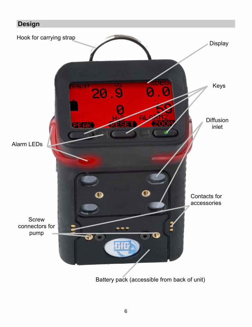
Design
Hook for carrying strap
Alarm LEDs
Diffusion inlet
Keys
Display
Contacts for accessories
Battery pack (accessible from back of unit)
Screw connectors for
pump
7
Operation GfG recommends frequent verification of accuracy. The safest course of action is to verify accuracy with a known concentration of gas prior to each day’s use. If the readings are less than 90% or greater than 120% (-10% to +20% accuracy) the detector must be calibrated before use. In compliance with c-CSA (Canada) the following requirements must be observed: CAUTION: Before each use, sensitivity must be tested on a known
concentration of CO, H2S and combustible gas (depending on which sensors are installed) equivalent to 25 to 50% of the full scale concentration. Accuracy must be within -0 to 20% of the actual measurement.
Accuracy may be corrected by performing an AutoCal® adjustment (see calibration). Detection Mode
Turning the Device On
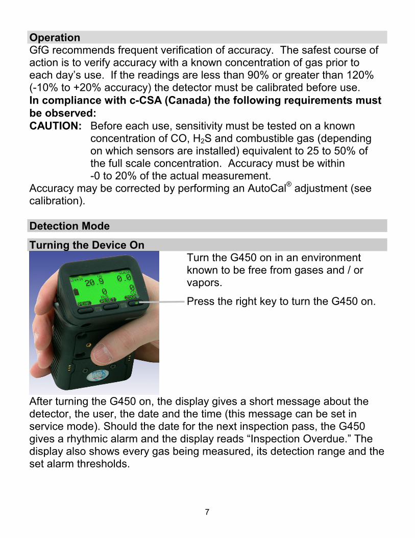
Turn the G450 on in an environment known to be free from gases and / or vapors.
Press the right key to turn the G450 on.
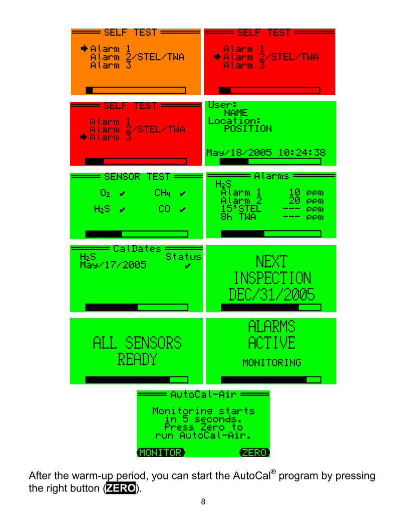
After turning the G450 on, the display gives a short message about the detector, the user, the date and the time (this message can be set in service mode). Should the date for the next inspection pass, the G450 gives a rhythmic alarm and the display reads “Inspection Overdue.” The display also shows every gas being measured, its detection range and the set alarm thresholds.
8
After the warm-up period, you can start the AutoCal® program by pressing the right button (ZERO).
9
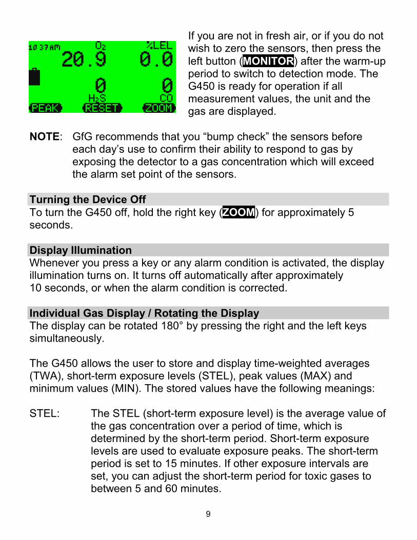
If you are not in fresh air, or if you do not wish to zero the sensors, then press the left button (MONITOR) after the warm-up period to switch to detection mode. The G450 is ready for operation if all measurement values, the unit and the gas are displayed.
NOTE: GfG recommends that you “bump check” the sensors before
each day’s use to confirm their ability to respond to gas by exposing the detector to a gas concentration which will exceed the alarm set point of the sensors.
Turning the Device Off
To turn the G450 off, hold the right key (ZOOM) for approximately 5 seconds.
Display Illumination Whenever you press a key or any alarm condition is activated, the display illumination turns on. It turns off automatically after approximately 10 seconds, or when the alarm condition is corrected.
Individual Gas Display / Rotating the Display The display can be rotated 180° by pressing the right and the left keys simultaneously.
The G450 allows the user to store and display time-weighted averages (TWA), short-term exposure levels (STEL), peak values (MAX) and minimum values (MIN). The stored values have the following meanings: STEL: The STEL (short-term exposure level) is the average value of
the gas concentration over a period of time, which is determined by the short-term period. Short-term exposure levels are used to evaluate exposure peaks. The short-term period is set to 15 minutes. If other exposure intervals are set, you can adjust the short-term period for toxic gases to between 5 and 60 minutes.
10
TWA: The time-weighted average (TWA) is the average value of the gas concentration over an 8 hour working shift. For calculating the total dose, the G450 uses all gas levels measured since the detector was turned on.
MIN / MAX: Minimum and peak values measured since the detector was
switched on or since the stored values were reset.
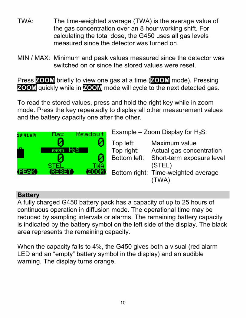
Press ZOOM briefly to view one gas at a time (ZOOM mode). Pressing ZOOM quickly while in ZOOM mode will cycle to the next detected gas. To read the stored values, press and hold the right key while in zoom mode. Press the key repeatedly to display all other measurement values and the battery capacity one after the other.
Example – Zoom Display for H2S:
Top left: Maximum value Top right: Actual gas concentration Bottom left: Short-term exposure level
(STEL) Bottom right: Time-weighted average
(TWA)
Battery A fully charged G450 battery pack has a capacity of up to 25 hours of continuous operation in diffusion mode. The operational time may be reduced by sampling intervals or alarms. The remaining battery capacity is indicated by the battery symbol on the left side of the display. The black area represents the remaining capacity.
When the capacity falls to 4%, the G450 gives both a visual (red alarm LED and an “empty” battery symbol in the display) and an audible warning. The display turns orange.
11
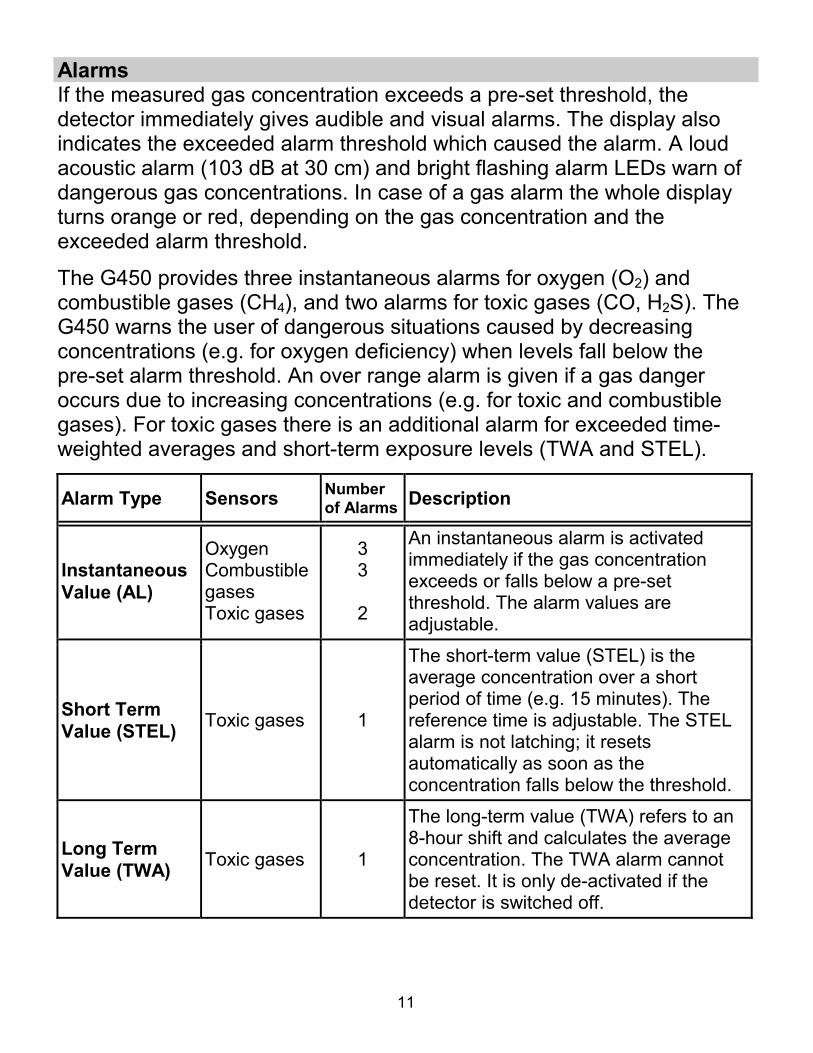
Alarms If the measured gas concentration exceeds a pre-set threshold, the detector immediately gives audible and visual alarms. The display also indicates the exceeded alarm threshold which caused the alarm. A loud acoustic alarm (103 dB at 30 cm) and bright flashing alarm LEDs warn of dangerous gas concentrations. In case of a gas alarm the whole display turns orange or red, depending on the gas concentration and the exceeded alarm threshold.
The G450 provides three instantaneous alarms for oxygen (O2) and combustible gases (CH4), and two alarms for toxic gases (CO, H2S). The G450 warns the user of dangerous situations caused by decreasing concentrations (e.g. for oxygen deficiency) when levels fall below the pre-set alarm threshold. An over range alarm is given if a gas danger occurs due to increasing concentrations (e.g. for toxic and combustible gases). For toxic gases there is an additional alarm for exceeded time-weighted averages and short-term exposure levels (TWA and STEL).
Alarm Type Sensors Number of Alarms Description
Instantaneous Value (AL)
Oxygen Combustible gases Toxic gases
3 3 2
An instantaneous alarm is activated immediately if the gas concentration exceeds or falls below a pre-set threshold. The alarm values are adjustable.
Short Term Value (STEL) Toxic gases 1
The short-term value (STEL) is the average concentration over a short period of time (e.g. 15 minutes). The reference time is adjustable. The STEL alarm is not latching; it resets automatically as soon as the concentration falls below the threshold.
Long Term Value (TWA) Toxic gases 1
The long-term value (TWA) refers to an 8-hour shift and calculates the average concentration. The TWA alarm cannot be reset. It is only de-activated if the detector is switched off.
12
Resetting Latching Alarms For alarms 2 and 3, when alarms are set to latching you must reset an activated alarm by pressing the RESET key. Alarm 1 will automatically reset when the gas danger has passed. If the detection range of the CH4 sensor is exceeded, the display will read “OVER RANGE” instead of a value for gas concentrations above 110% LEL. To protect the sensor from damage, the device turns off the sensor. However, the audible and visual alarms and the “OVER RANGE” message remain active. The alarms must be reset by pushing the RESET key. The display will read: “Fresh air?” If you have made sure that there is no combustible gas in the vicinity of the CH4 sensor, press yes to resume detection.
STEL, TWA, Maximum / Minimum Values When you turn the G450 on, the unit begins to measure continuously in diffusion mode. All concentrations are shown on the display. In addition, short term and long-term averages (STEL and TWA) are calculated for toxic gases; for non-toxic gases peak and minimum values (MAX and MIN) are stored. The stored values can be read from the display by accessing the applicable display mode. WARNING: To avoid possible personal injury, do not turn off the detector
during a work shift. TWA, STEL and MAX readings are reset when the G450 is turned off.
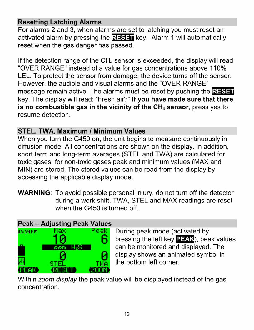
Peak – Adjusting Peak Values
During peak mode (activated by pressing the left key PEAK), peak values can be monitored and displayed. The display shows an animated symbol in the bottom left corner.
Within zoom display the peak value will be displayed instead of the gas concentration.

13
Pressing RESET during peak mode will reset the peak memory to the current gas concentration. Pressing RESET during zoom display will reset the peak memory and the peak value memory to the current gas concentration. By pressing PEAK again peak mode is deactivated. Service Mode Hold the middle key (RESET) for approximately 5 seconds to activate service mode. In the service mode the program parameters of the G450 can be adjusted and changed. A menu highlights the different adjustment possibilities. Several menu points require an access code (0011) to prevent accidental modification of important functions. In service mode all alarms are deactivated. All adjustments in service mode are menu-controlled. The 3 keys stand for the function which is shown in the bottom line of the display. The main menu is displayed first when you enter service mode. Main Menu The menu points are: 1. Location (the physical location of the G450) 2. User (user identity) 3. Datalogger (adjust datalogger function) 4. Confidence blip (adjust intervals) 5. Service (start service menu) 6. AutoCal® 7. Options (adjust alarm volume and display contrast) The keys’ functions are explained in the bottom line of the display. In the main menu the keys have the following functions:
Left key (↓↓ scroll down) Middle key (SELECT) select menu point Right key (DETECT) back to detection mode

14
Location – Entering a Location From a deposited table one location out of a hundred possible locations can be selected. The first two digits stand for the number of the table entry. With the exception of “00” all other 99 entries can only be edited with a PC. Within “00” up to 15 letters / figures can be entered, which will be stored as operational place in the G450. Entry is automatically completed when the cursor reaches the end mark (>). When Location is selected by the middle key (SELECT), the following is displayed, and the keys have the following functions:
First a location number is specified: EDIT - Change location name EXIT - Back to main menu ↑↑ - Change location number
After selecting a location number (by pressing the right key – ↑↑) the location entry will be displayed. To change the location, press the left key (EDIT). The following is displayed, and the keys have the following functions:
ABC↓↓ - Select symbol – move down <<>> - Enter the blinking letter or
figure and move the cursor to the right
012↑↑ - Select symbol – move up User – Entering User Name From a deposited table one entry out of ten possible entries can be selected. The first two digits stand for the number of the table entry. Except for “00,” the other 9 entries can only be edited with a PC. Within “00” up to 15 characters can be entered, which will be stored as “IDENTIFICATION” in the G450. Entry is automatically completed when the cursor reaches the end mark (>). The entry process for user name (ID) is the same as that of the location entry.
15
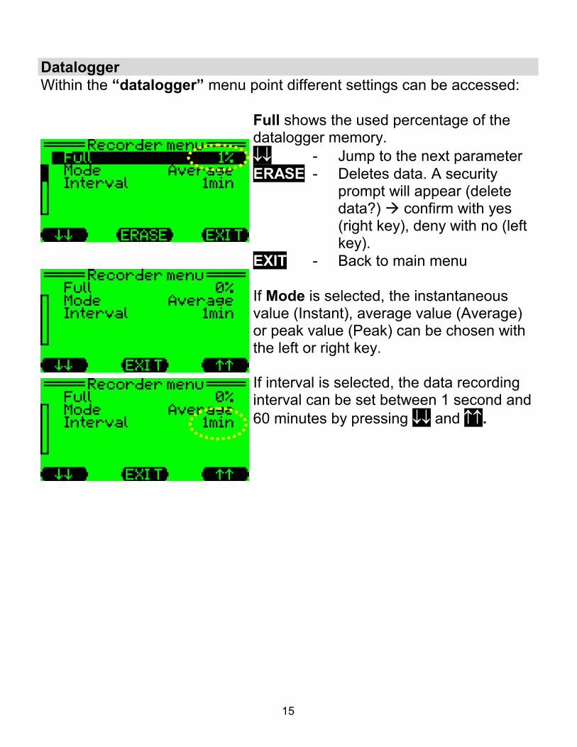
Datalogger Within the “datalogger” menu point different settings can be accessed:
Full shows the used percentage of the datalogger memory. ↓↓ - Jump to the next parameter ERASE - Deletes data. A security
prompt will appear (delete data?) confirm with yes (right key), deny with no (left key).
EXIT - Back to main menu If Mode is selected, the instantaneous value (Instant), average value (Average) or peak value (Peak) can be chosen with the left or right key. If interval is selected, the data recording interval can be set between 1 second and 60 minutes by pressing ↓↓ and ↑↑.
16
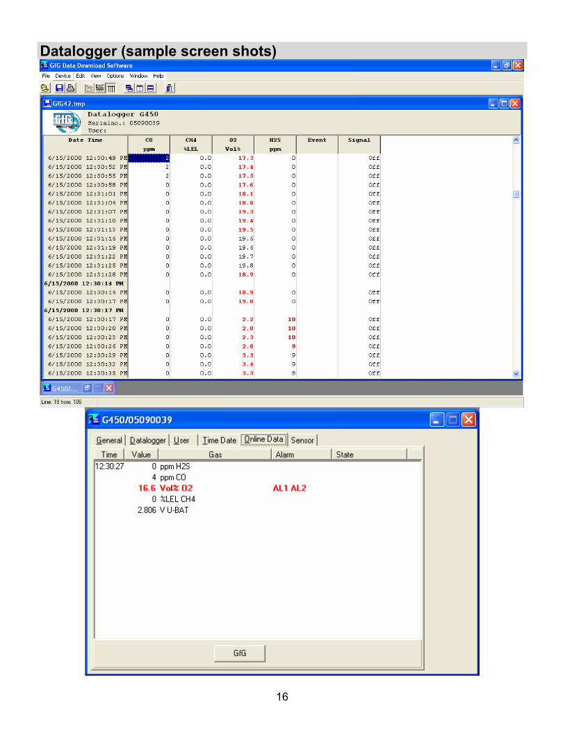
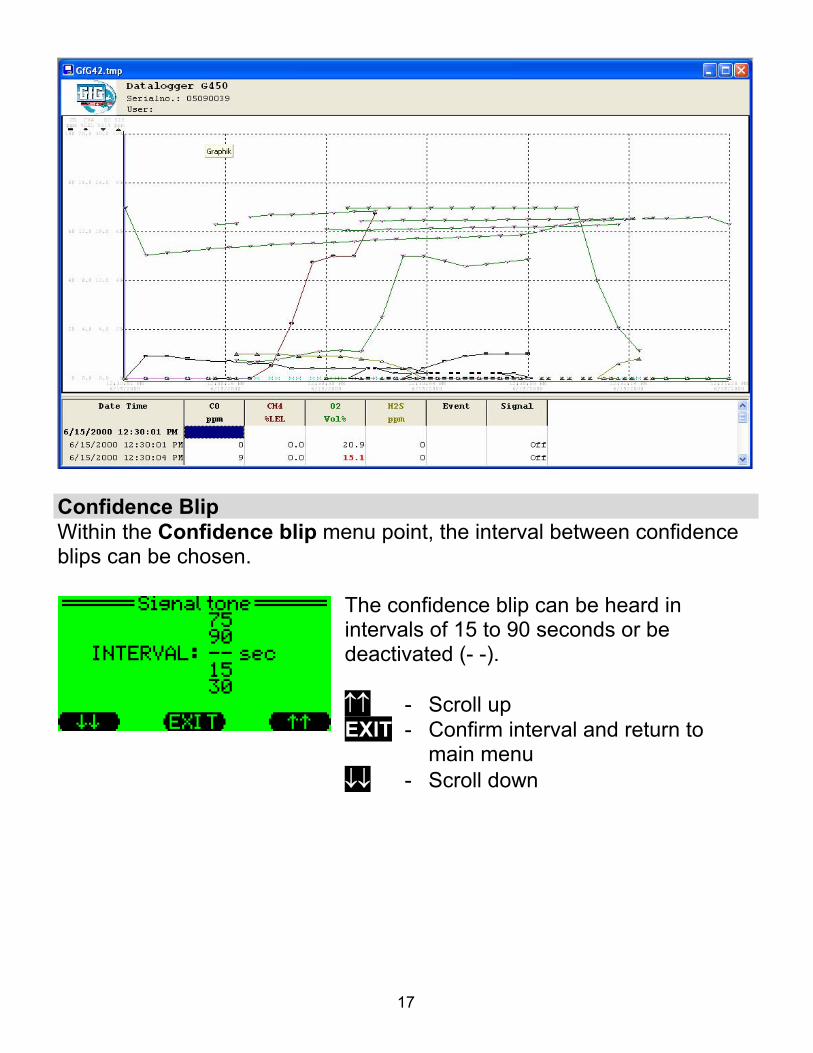
Datalogger (sample screen shots)
17
Confidence Blip Within the Confidence blip menu point, the interval between confidence blips can be chosen.
The confidence blip can be heard in intervals of 15 to 90 seconds or be deactivated (- -). ↑↑ - Scroll up EXIT - Confirm interval and return to
main menu ↓↓ - Scroll down

18
AutoCal® The AutoCal® menu point can be selected in the main menu or occurs automatically when the calibration adapter (Smart Cap) is connected. Within the AutoCal® menu point the device can be calibrated with fresh air (ZERO) or test gas (CAL).
ZERO - AutoCal® with fresh air CAL - AutoCal® with test gas EXIT - Back to main menu
Options Within Options you can adjust • The buzzer volume (90 dB or 103 dB) • The screen contrast: 1 (very low) up to 15 (very high)
↓↓ - Scroll down CHANGE - Change selected parameter EXIT - Back to main menu
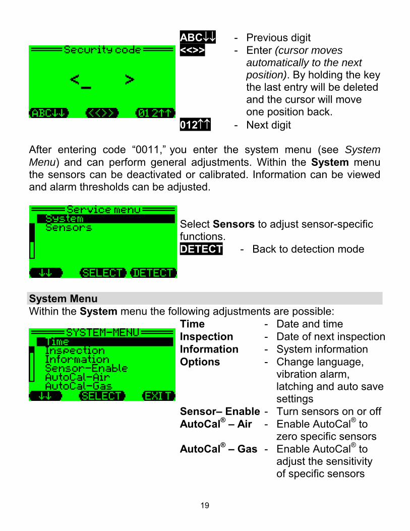
Service Menu Enter the service menu by selecting Service. Within the service menu the G450 program parameters can be adjusted. This menu point is only accessible with the code “0011.” The code prevents important functions from being changed by mistake or by unauthorized persons. In service mode all alarms are suppressed.
19
ABC↓↓ - Previous digit <<>> - Enter (cursor moves
automatically to the next position). By holding the key the last entry will be deleted and the cursor will move one position back.
012↑↑ - Next digit After entering code “0011,” you enter the system menu (see System Menu) and can perform general adjustments. Within the System menu the sensors can be deactivated or calibrated. Information can be viewed and alarm thresholds can be adjusted.
Select Sensors to adjust sensor-specific functions. DETECT - Back to detection mode
System Menu Within the System menu the following adjustments are possible:
Time - Date and time Inspection - Date of next inspection Information - System information Options - Change language,
vibration alarm, latching and auto save settings
Sensor– Enable - Turn sensors on or off AutoCal® – Air - Enable AutoCal® to
zero specific sensors AutoCal® – Gas - Enable AutoCal® to
adjust the sensitivity of specific sensors

20
Time The blinking parameter is selected by pressing SELECT. >> moves to the next parameter. EXIT returns to the system menu.
To change a parameter, the following options are available: ↓↓ - Decreases value EXIT - Confirms value ↑↑ - Increases value
Inspection The date of the next maintenance or inspection can be entered under the Inspection menu. When the date arrives, the G450 will automatically sound an alarm. If the inspection date passes, the G450 will give a reminder every time it is switched on. Within the system menu, select Inspection.
EXIT - Back to system menu SELECT - Selects the blinking
parameter >> - Moves to the next
parameter To change a parameter: ↓↓ - Decreases value EXIT - Confirms value ↑↑ - Increases value
Information The unit type (G450), software version, serial number and battery type can be viewed in the system menu point Information.

21
Options In the Options menu point, the language can be changed, the vibrating alarm can be activated or deactivated and the latching and auto save features can be turned on or off. ↓↓ - Scroll down CHANGE - Change setting for the selected option EXIT - Return to system menu
Latching Alarm Function The detector is shipped with the latching alarm function disabled. If the alarms are set to latch, the audible and visual alarms will persist until the alarm is acknowledged by pressing the center key (RESET). To enable latching alarms, press the left key (↓↓) until Latching is highlighted. Press the center key (CHANGE) to enable latching alarms. Sensor – Enable Each individual sensor can be activated or deactivated for each measurement. This function is necessary for applications in which a gas does not need to be measured or if the G450 will be upgraded with different sensors. ON or OFF indicates the status of the sensor (active or inactive). An indicator in parenthesis – (ON) or (OFF) – means that the sensor is not available. These indicators have the same meaning in the AutoCal® – Air and AutoCal® – Gas menus.
ON - Sensor active OFF - Sensor inactive (ON) / (OFF) - Sensor not available ↓↓ - Scroll down On / Off - Activate/deactivate sensor EXIT - Return to system menu
22
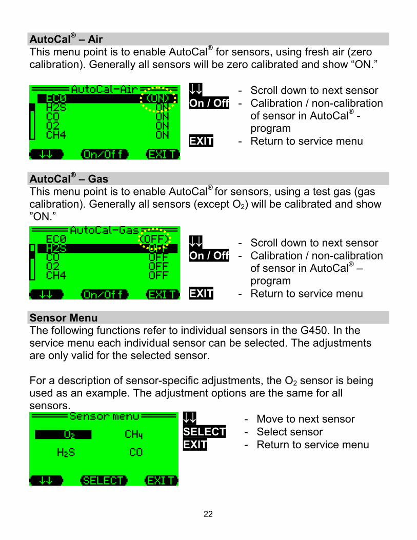
AutoCal® – Air This menu point is to enable AutoCal® for sensors, using fresh air (zero calibration). Generally all sensors will be zero calibrated and show “ON.”
↓↓ - Scroll down to next sensor On / Off - Calibration / non-calibration
of sensor in AutoCal® - program
EXIT - Return to service menu AutoCal® – Gas This menu point is to enable AutoCal® for sensors, using a test gas (gas calibration). Generally all sensors (except O2) will be calibrated and show ”ON.”
↓↓ - Scroll down to next sensor On / Off - Calibration / non-calibration
of sensor in AutoCal® – program
EXIT - Return to service menu
Sensor Menu The following functions refer to individual sensors in the G450. In the service menu each individual sensor can be selected. The adjustments are only valid for the selected sensor. For a description of sensor-specific adjustments, the O2 sensor is being used as an example. The adjustment options are the same for all sensors.
↓↓ - Move to next sensor SELECT - Select sensor EXIT - Return to service menu
23
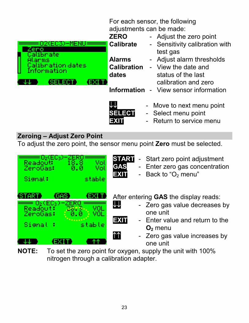
For each sensor, the following adjustments can be made: ZERO - Adjust the zero point Calibrate - Sensitivity calibration with
test gas Alarms - Adjust alarm thresholds Calibration - View the date and dates status of the last
calibration and zero Information - View sensor information ↓↓ - Move to next menu point SELECT - Select menu point EXIT - Return to service menu
Zeroing – Adjust Zero Point To adjust the zero point, the sensor menu point Zero must be selected.
START - Start zero point adjustment GAS - Enter zero gas concentration EXIT - Back to “O2 menu”
After entering GAS the display reads: ↓↓ - Zero gas value decreases by
one unit EXIT - Enter value and return to the
O2 menu ↑↑ - Zero gas value increases by
one unit NOTE: To set the zero point for oxygen, supply the unit with 100%
nitrogen through a calibration adapter.
24
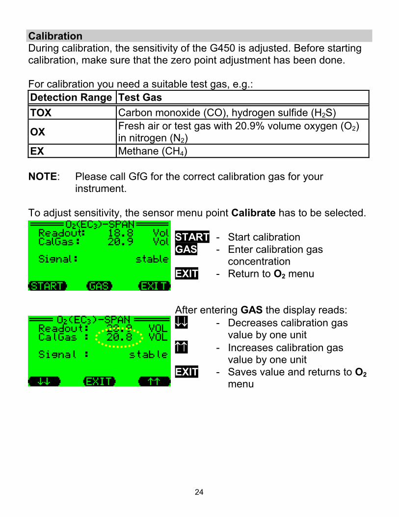
Calibration During calibration, the sensitivity of the G450 is adjusted. Before starting calibration, make sure that the zero point adjustment has been done. For calibration you need a suitable test gas, e.g.: Detection Range Test Gas TOX Carbon monoxide (CO), hydrogen sulfide (H2S)
OX Fresh air or test gas with 20.9% volume oxygen (O2) in nitrogen (N2)
EX Methane (CH4)
NOTE: Please call GfG for the correct calibration gas for your instrument.
To adjust sensitivity, the sensor menu point Calibrate has to be selected.
START - Start calibration GAS - Enter calibration gas
concentration EXIT - Return to O2 menu
After entering GAS the display reads: ↓↓ - Decreases calibration gas
value by one unit ↑↑ - Increases calibration gas
value by one unit EXIT - Saves value and returns to O2
menu
25
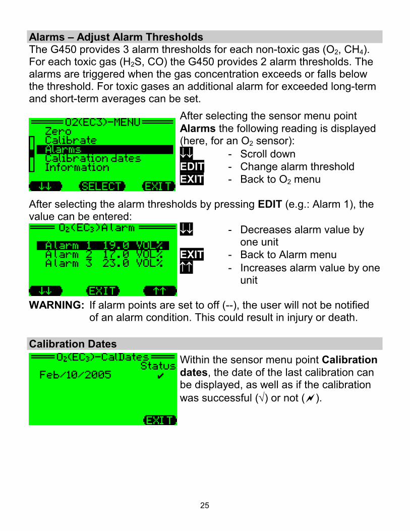
Alarms – Adjust Alarm Thresholds The G450 provides 3 alarm thresholds for each non-toxic gas (O2, CH4). For each toxic gas (H2S, CO) the G450 provides 2 alarm thresholds. The alarms are triggered when the gas concentration exceeds or falls below the threshold. For toxic gases an additional alarm for exceeded long-term and short-term averages can be set.
After selecting the sensor menu point Alarms the following reading is displayed (here, for an O2 sensor): ↓↓ - Scroll down EDIT - Change alarm threshold EXIT - Back to O2 menu
After selecting the alarm thresholds by pressing EDIT (e.g.: Alarm 1), the value can be entered:
↓↓ - Decreases alarm value by one unit
EXIT - Back to Alarm menu ↑↑ - Increases alarm value by one
unit
WARNING: If alarm points are set to off (--), the user will not be notified of an alarm condition. This could result in injury or death.
Calibration Dates
Within the sensor menu point Calibration dates, the date of the last calibration can be displayed, as well as if the calibration was successful (√) or not ( ).
26
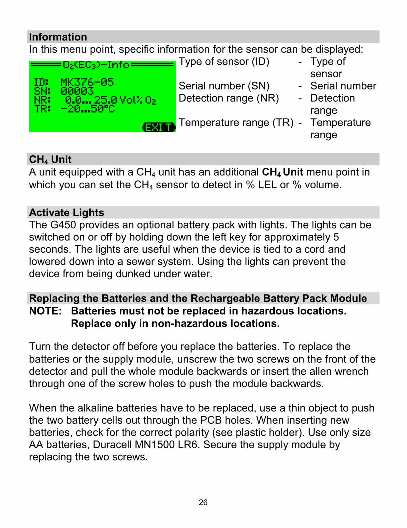
Information In this menu point, specific information for the sensor can be displayed:
Type of sensor (ID) - Type of sensor
Serial number (SN) - Serial number Detection range (NR) - Detection
range Temperature range (TR) - Temperature
range
CH4 Unit A unit equipped with a CH4 unit has an additional CH4 Unit menu point in which you can set the CH4 sensor to detect in % LEL or % volume.
Activate Lights The G450 provides an optional battery pack with lights. The lights can be switched on or off by holding down the left key for approximately 5 seconds. The lights are useful when the device is tied to a cord and lowered down into a sewer system. Using the lights can prevent the device from being dunked under water. Replacing the Batteries and the Rechargeable Battery Pack Module NOTE: Batteries must not be replaced in hazardous locations.
Replace only in non-hazardous locations. Turn the detector off before you replace the batteries. To replace the batteries or the supply module, unscrew the two screws on the front of the detector and pull the whole module backwards or insert the allen wrench through one of the screw holes to push the module backwards. When the alkaline batteries have to be replaced, use a thin object to push the two battery cells out through the PCB holes. When inserting new batteries, check for the correct polarity (see plastic holder). Use only size AA batteries, Duracell MN1500 LR6. Secure the supply module by replacing the two screws.
27
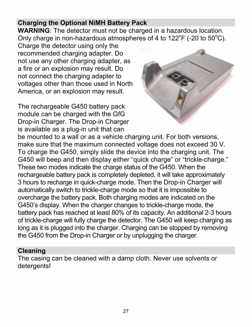
Charging the Optional NiMH Battery Pack WARNING: The detector must not be charged in a hazardous location. Only charge in non-hazardous atmospheres of 4 to 122oF (-20 to 50oC). Charge the detector using only the recommended charging adapter. Do not use any other charging adapter, as a fire or an explosion may result. Do not connect the charging adapter to voltages other than those used in North America, or an explosion may result. The rechargeable G450 battery pack module can be charged with the GfG Drop-in Charger. The Drop-in Charger is available as a plug-in unit that can be mounted to a wall or as a vehicle charging unit. For both versions, make sure that the maximum connected voltage does not exceed 30 V. To charge the G450, simply slide the device into the charging unit. The G450 will beep and then display either “quick charge” or “trickle-charge.” These two modes indicate the charge status of the G450. When the rechargeable battery pack is completely depleted, it will take approximately 3 hours to recharge in quick-charge mode. Then the Drop-in Charger will automatically switch to trickle-charge mode so that it is impossible to overcharge the battery pack. Both charging modes are indicated on the G450’s display. When the charger changes to trickle-charge mode, the battery pack has reached at least 80% of its capacity. An additional 2-3 hours of trickle-charge will fully charge the detector. The G450 will keep charging as long as it is plugged into the charger. Charging can be stopped by removing the G450 from the Drop-in Charger or by unplugging the charger. Cleaning The casing can be cleaned with a damp cloth. Never use solvents or detergents!

28
Maintenance and Inspection Maintenance includes service, calibration and adjustment, as well as repair if it is necessary. Gas monitoring devices can react differently depending on environmental conditions. It is important, independent from maintenance duties, to test the device before putting it into operation each day. Bump testing before each use is highly recommended. Service – Repair WARNING: To avoid personal injury or damage to the detector, use only
the specified replacement parts. A function test must be executed before the first operation and at least once a year. This test comprises (depending on use and sensor exposure to poisons and contamination): • Check zero point • Charge battery (optional) • Check pump (optional) and diffusion inlets • Test display with standard test gas (bump test) and adjust, if necessary • Check alarm signals • Test response time NOTE: GfG recommends that you “bump check” the sensors before
each day’s use to confirm their ability to respond to gas by exposing the detector to a gas concentration which will exceed the alarm set point of the sensor.
Any G450 repair must be done according to the manufacturer’s instructions and with genuine spare parts. Return to GfG for proper service.
29
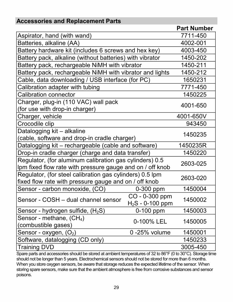
Accessories and Replacement Parts Part NumberAspirator, hand (with wand) 7711-450 Batteries, alkaline (AA) 4002-001 Battery hardware kit (includes 6 screws and hex key) 4003-450 Battery pack, alkaline (without batteries) with vibrator 1450-202 Battery pack, rechargeable NiMH with vibrator 1450-211 Battery pack, rechargeable NiMH with vibrator and lights 1450-212 Cable, data downloading / USB interface (for PC) 1650231 Calibration adapter with tubing 7771-450 Calibration connector 1450225 Charger, plug-in (110 VAC) wall pack (for use with drop-in charger) 4001-650
Charger, vehicle 4001-650V Crocodile clip 943450 Datalogging kit – alkaline (cable, software and drop-in cradle charger) 1450235
Datalogging kit – rechargeable (cable and software) 1450235R Drop-in cradle charger (charge and data transfer) 1450220 Regulator, (for aluminum calibration gas cylinders) 0.5 lpm fixed flow rate with pressure gauge and on / off knob 2603-025
Regulator, (for steel calibration gas cylinders) 0.5 lpm fixed flow rate with pressure gauge and on / off knob 2603-020
Sensor - carbon monoxide, (CO) 0-300 ppm 1450004
Sensor - COSH – dual channel sensor CO - 0-300 ppm H2S - 0-100 ppm 1450002
Sensor - hydrogen sulfide, (H2S) 0-100 ppm 1450003 Sensor - methane, (CH4) (combustible gases) 0-100% LEL 1450005
Sensor - oxygen, (O2) 0 -25% volume 1450001 Software, datalogging (CD only) 1450233 Training DVD 3005-450 Spare parts and accessories should be stored at ambient temperatures of 32 to 86°F (0 to 30°C). Storage time should not be longer than 5 years. Electrochemical sensors should not be stored for more than 6 months. When you store oxygen sensors, be aware that storage reduces the expected lifetime of the sensor. When storing spare sensors, make sure that the ambient atmosphere is free from corrosive substances and sensor poisons.
30
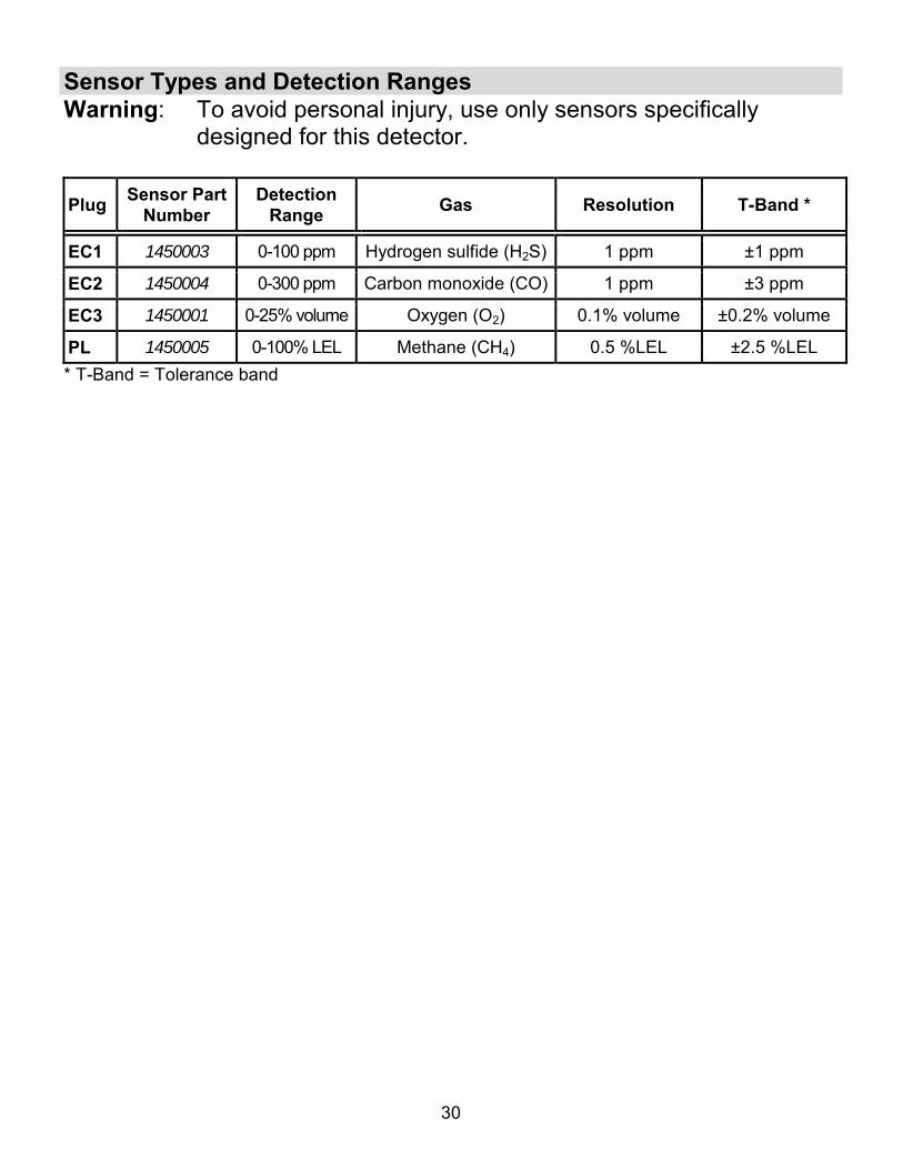
Sensor Types and Detection Ranges Warning: To avoid personal injury, use only sensors specifically
designed for this detector.
Plug Sensor Part Number
Detection Range Gas Resolution T-Band *
EC1 1450003 0-100 ppm Hydrogen sulfide (H2S) 1 ppm ±1 ppm
EC2 1450004 0-300 ppm Carbon monoxide (CO) 1 ppm ±3 ppm
EC3 1450001 0-25% volume Oxygen (O2) 0.1% volume ±0.2% volume
PL 1450005 0-100% LEL Methane (CH4) 0.5 %LEL ±2.5 %LEL * T-Band = Tolerance band
31
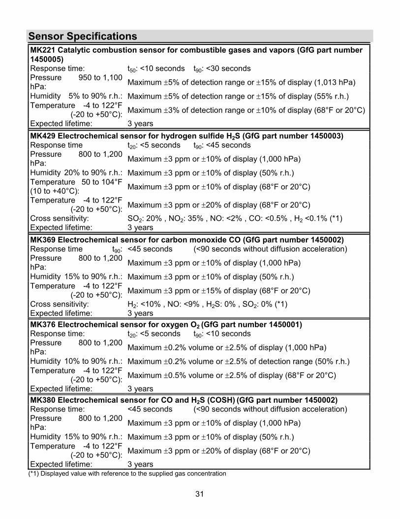
Sensor Specifications MK221 Catalytic combustion sensor for combustible gases and vapors (GfG part number 1450005) Response time: t50: <10 seconds t90: <30 seconds Pressure 950 to 1,100 hPa: Maximum ±5% of detection range or ±15% of display (1,013 hPa)
Humidity 5% to 90% r.h.: Maximum ±5% of detection range or ±15% of display (55% r.h.) Temperature -4 to 122°F (-20 to +50°C): Maximum ±3% of detection range or ±10% of display (68°F or 20°C)
Expected lifetime: 3 years MK429 Electrochemical sensor for hydrogen sulfide H2S (GfG part number 1450003) Response time t20: <5 seconds t90: <45 seconds Pressure 800 to 1,200 hPa: Maximum ±3 ppm or ±10% of display (1,000 hPa)
Humidity 20% to 90% r.h.: Maximum ±3 ppm or ±10% of display (50% r.h.) Temperature 50 to 104°F (10 to +40°C): Maximum ±3 ppm or ±10% of display (68°F or 20°C)
Temperature -4 to 122°F (-20 to +50°C): Maximum ±3 ppm or ±20% of display (68°F or 20°C)
Cross sensitivity: SO2: 20% , NO2: 35% , NO: <2% , CO: <0.5% , H2 <0.1% (*1) Expected lifetime: 3 years MK369 Electrochemical sensor for carbon monoxide CO (GfG part number 1450002) Response time t90: <45 seconds (<90 seconds without diffusion acceleration) Pressure 800 to 1,200 hPa: Maximum ±3 ppm or ±10% of display (1,000 hPa)
Humidity 15% to 90% r.h.: Maximum ±3 ppm or ±10% of display (50% r.h.) Temperature -4 to 122°F (-20 to +50°C): Maximum ±3 ppm or ±15% of display (68°F or 20°C)
Cross sensitivity: H2: <10% , NO: <9% , H2S: 0% , SO2: 0% (*1) Expected lifetime: 3 years MK376 Electrochemical sensor for oxygen O2 (GfG part number 1450001) Response time: t20: <5 seconds t90: <10 seconds Pressure 800 to 1,200 hPa: Maximum ±0.2% volume or ±2.5% of display (1,000 hPa)
Humidity 10% to 90% r.h.: Maximum ±0.2% volume or ±2.5% of detection range (50% r.h.) Temperature -4 to 122°F (-20 to +50°C): Maximum ±0.5% volume or ±2.5% of display (68°F or 20°C)
Expected lifetime: 3 years MK380 Electrochemical sensor for CO and H2S (COSH) (GfG part number 1450002) Response time: <45 seconds (<90 seconds without diffusion acceleration) Pressure 800 to 1,200 hPa: Maximum ±3 ppm or ±10% of display (1,000 hPa)
Humidity 15% to 90% r.h.: Maximum ±3 ppm or ±10% of display (50% r.h.) Temperature -4 to 122°F (-20 to +50°C): Maximum ±3 ppm or ±20% of display (68°F or 20°C)
Expected lifetime: 3 years (*1) Displayed value with reference to the supplied gas concentration
32
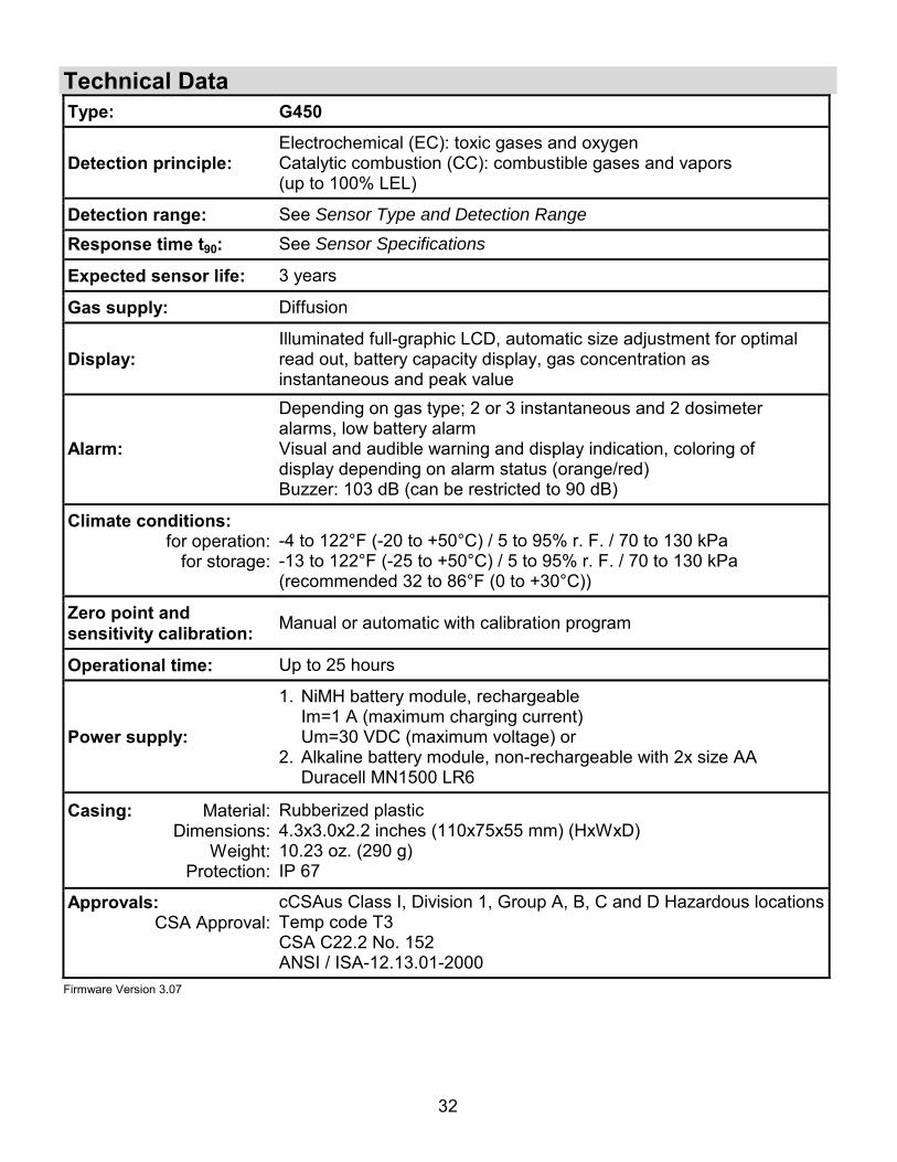
Technical Data Type: G450
Detection principle: Electrochemical (EC): toxic gases and oxygen Catalytic combustion (CC): combustible gases and vapors (up to 100% LEL)
Detection range: See Sensor Type and Detection Range
Response time t90: See Sensor Specifications
Expected sensor life: 3 years
Gas supply: Diffusion
Display: Illuminated full-graphic LCD, automatic size adjustment for optimal read out, battery capacity display, gas concentration as instantaneous and peak value
Alarm:
Depending on gas type; 2 or 3 instantaneous and 2 dosimeter alarms, low battery alarm Visual and audible warning and display indication, coloring of display depending on alarm status (orange/red) Buzzer: 103 dB (can be restricted to 90 dB)
Climate conditions: for operation:
for storage:
-4 to 122°F (-20 to +50°C) / 5 to 95% r. F. / 70 to 130 kPa -13 to 122°F (-25 to +50°C) / 5 to 95% r. F. / 70 to 130 kPa (recommended 32 to 86°F (0 to +30°C))
Zero point and sensitivity calibration: Manual or automatic with calibration program
Operational time: Up to 25 hours
Power supply:
1. NiMH battery module, rechargeable Im=1 A (maximum charging current) Um=30 VDC (maximum voltage) or
2. Alkaline battery module, non-rechargeable with 2x size AA Duracell MN1500 LR6
Casing: Material: Dimensions:
Weight: Protection:
Rubberized plastic 4.3x3.0x2.2 inches (110x75x55 mm) (HxWxD) 10.23 oz. (290 g) IP 67
Approvals:
CSA Approval: cCSAus Class I, Division 1, Group A, B, C and D Hazardous locations Temp code T3 CSA C22.2 No. 152 ANSI / ISA-12.13.01-2000
Firmware Version 3.07
33
Caution Substituting components may hinder intrinsic safety. For safety reasons, this equipment must be operated and serviced by qualified personnel only. Read and understand the user manual completely before operating or servicing this device.
Do not use the detector if it is damaged. Before you use the detector, inspect the case. Look for cracks or missing parts.
If the detector is damaged or something is missing, contact GfG Instrumentation, Inc. immediately.
Calibrate the detector before first-time use and then on a regular schedule, depending on use and sensor exposure to poisons and contaminants.
GfG recommends that you “bump test” the sensors before each use to confirm their ability to respond to gas. To do this, expose the detector to a gas concentration that exceeds the alarm set points. Manually verify that the audible and visual alarms are activated. Calibrate if the readings are not within the specified limits.
It is recommended that the combustible sensor be checked with a known concentration of calibration gas after any known exposure to catalyst contaminants/poisons (sulfur compounds, silicon vapors, halogenated compounds, etc).
The combustible sensor is factory calibrated to 50% LEL methane. If monitoring a different combustible gas in the % LEL range, calibrate the sensor using the appropriate gas.
High off-scale readings may indicate an explosive concentration. Only the combustible gas detection portion of this instrument has been assessed for performance by CSA International.
Protect the combustible sensor from exposure to lead compounds, silicones and chlorinated hydrocarbons. Although certain organic vapors (such as leaded gasoline and halogenated hydrocarbons) may temporarily inhibit sensor performance, in most cases the sensor will recover after calibration.
For use only in hazardous locations where oxygen concentrations do not exceed 20.9% volume (v/v).
Any rapidly increasing reading followed by a declining or erratic reading may indicate a gas concentration beyond the upper scale limit, which may be hazardous.
34
Extended exposure of the G450 to certain concentrations of combustible gases and air may stress detector elements, which can seriously affect the device’s performance. If an alarm occurs due to a high concentration of combustible gases, recalibration should be performed, or if needed, the sensor replaced.
Do not test the combustible sensor’s response with a butane cigarette lighter; doing so can damage the sensor.
Do not expose the detector to electrical shock and/or severe continuous mechanical shock.
Do not attempt to disassemble, adjust or service the detector unless instructions for that procedure are contained in the manual and/or that part is listed as a replacement part.
Electromagnetic interference (EMI) signals may cause incorrect operation of this detector.
Warranty GfG Instrumentation warrants our products to be free from defects in material and workmanship when used for their intended purpose, and agrees to remedy any such defect or to furnish a new part (at the option of GfG Instrumentation) in exchange for any part of any product that we manufacture that under normal use is found to be defective; provided that the product is returned, by the purchaser, to GfG’s factory, intact, for our examination, with all transportation costs prepaid, and provided that such examination reveals, in our judgment, that it is defective. This warranty does not extend to any products that have been subjected to misuse, neglect, accident, or unauthorized modifications; nor does it extend to products used contrary to the instructions furnished by us or to products that have been repaired or altered outside of our factory. No agent or reseller of GfG Instrumentation may alter the above statements.

35
G450/460 Motorized Pump
Application and Use The G450/460 motorized pump ensures personal safety in atmospheric conditions in combination with the portable gas detectors of the G400 series. The G450/460 pump is designed for use in explosion endangered areas and is designed for conformity with ATEX II2G Ex ia IIC T4 or T3. Special Conditions for Safe Use In hazardous locations the G450/460 pump must be used properly; i.e., the pump (with a G400 series gas detector) must be carried with you and must not be laid down unattended (to prevent electrostatic charge). The pump must be attached to the G400 gas detector before entering a hazardous location. It must not be disconnected from the detector in the hazardous location. Always pay attention to the ignition protection and the temperature class of the gas detector.

36
General Description and Design The G450/460 pump is a very small and convenient supplemental module for the G400 series gas detector. It allows gas sampling from a safe distance, without exposing the user to hazardous locations. The pump has its own power supply, which works independently from that of the G400 series monitor.
Sampling Inlet The sampling inlet is on the bottom of the pump body. Here you can attach accessories for taking gas samples (hose adapter with sampling line, probe, GfG telescopic probe).
Sampling inlet
Connection for gas sampling accessories
37
Connecting the Pump Attach the G450/460 pump to the G400 series gas detector and secure it with the thumbscrews. For permanent attachment to the G400 series gas detector you can attach the pump with 2 additional screws (included). You will find the mounting holes for the additional screws under the red sensor cover. To access the holes, slide the sensor cover upwards – push the lock smoothly with a screw driver – and remove it. Once the screws are in place, replace the sensor cover and slide it downwards. To remove the pump from the G400 series monitor, remove all attached screws.
Operational Hints
NOTE! If the red sensor cover is slid upwards forcefully, it may slip over its lock and the diffusion inlets will not be properly covered. This may result in false detection, since ambient air could dilute the concentration of the gas sample. Make sure, therefore, that the diffusion inlets are closed properly.
For sampling gases from sewers, rooms or drains, a hose (with or without a telescopic probe) that is plugged into the intake can be used. As the response time heavily depends on the internal volume of the intake hose, the length should be as short as possible. For the minimum pump time (Tmin in seconds) please adhere to the following calculation:
Tmin = 20s + 3s / m*Lhose + TTele
Lhose = length of hose (inner diameter 5 mm) in meters TTele = 10 s with telescopic probe, 0 s without
Turning the Pump On Slide the red sensor cover upwards to turn the pump on. With sufficient battery capacity the pump motor starts after a short delay (approximately 1 second). The battery capacity is indicated by flashing signals (see Test Battery Capacity). The proper operation of the pump is indicated by a continuously lit green LED (see Test Battery Capacity).
38
Turning the Pump Off Slide the red sensor cover downwards to turn the pump off. The pump should be turned off after detection to prevent unnecessary use of the batteries.
Confidence Signal During sampling, a green LED remains continuously lit to indicate trouble-free operation.
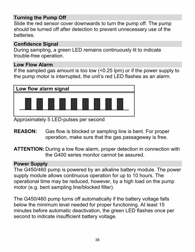
Low Flow Alarm If the sampled gas amount is too low (<0.25 lpm) or if the power supply to the pump motor is interrupted, the unit’s red LED flashes as an alarm. Low flow alarm signal
Approximately 5 LED-pulses per second REASON: Gas flow is blocked or sampling line is bent. For proper
operation, make sure that the gas passageway is free. ATTENTION: During a low flow alarm, proper detection in connection with
the G400 series monitor cannot be assured.
Power Supply The G450/460 pump is powered by an alkaline battery module. The power supply module allows continuous operation for up to 10 hours. The operational time may be reduced, however, by a high load on the pump motor (e.g. bent sampling line/blocked filter). The G450/460 pump turns off automatically if the battery voltage falls below the minimum level needed for proper functioning. At least 15 minutes before automatic deactivation, the green LED flashes once per second to indicate insufficient battery voltage.

39
Battery Replacement NOTE: The pump must not be opened in hazardous locations. Do not
replace the alkaline battery module in hazardous locations. Always turn the pump off before replacing the alkaline battery module. Check for the correct polarity of the new 1.5 V AA alkaline batteries (see Battery Holder). The correct battery type is: DURACELL PROCELL MN1500 LR6 AA. NOTE: The batteries may only be replaced in safe areas. Check for
correct polarity when inserting the batteries (see the picture inside the battery tray). With incorrect polarity the pump will not turn on.
To replace the batteries, separate the battery tray from the pump: unscrew the screws on the front and pull the battery tray out of the unit. Please adhere to disposal requirements!
Battery tray
40
NOTE: • Batteries must not be replaced in hazardous locations • Check for the correct polarity of the new batteries (see the picture on
inner side of battery tray)! • Check for correct insertion of the battery tray (characters on front must
be right side up)! Tighten all screws after inserting the battery tray.
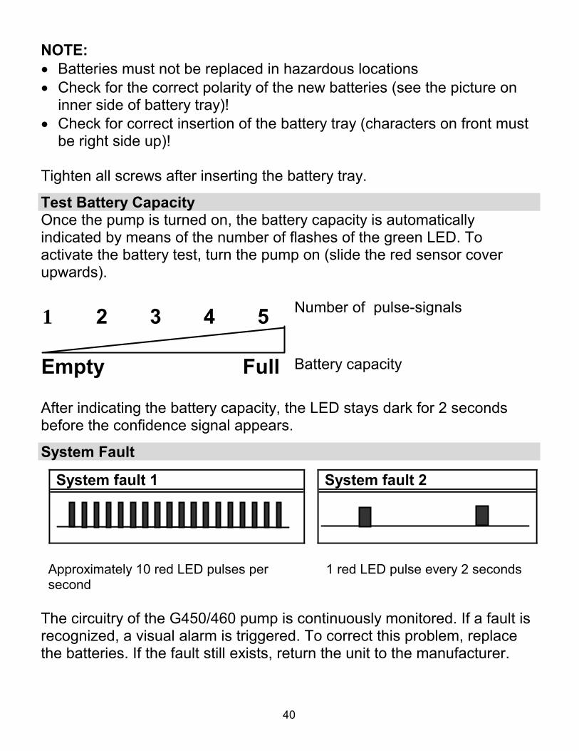
Test Battery Capacity Once the pump is turned on, the battery capacity is automatically indicated by means of the number of flashes of the green LED. To activate the battery test, turn the pump on (slide the red sensor cover upwards). 1 2 3 4 5
Empty Full
Number of pulse-signals
Battery capacity
After indicating the battery capacity, the LED stays dark for 2 seconds before the confidence signal appears.
System Fault
System fault 1
Approximately 10 red LED pulses per second
System fault 2
1 red LED pulse every 2 seconds
The circuitry of the G450/460 pump is continuously monitored. If a fault is recognized, a visual alarm is triggered. To correct this problem, replace the batteries. If the fault still exists, return the unit to the manufacturer.
41
Appendix
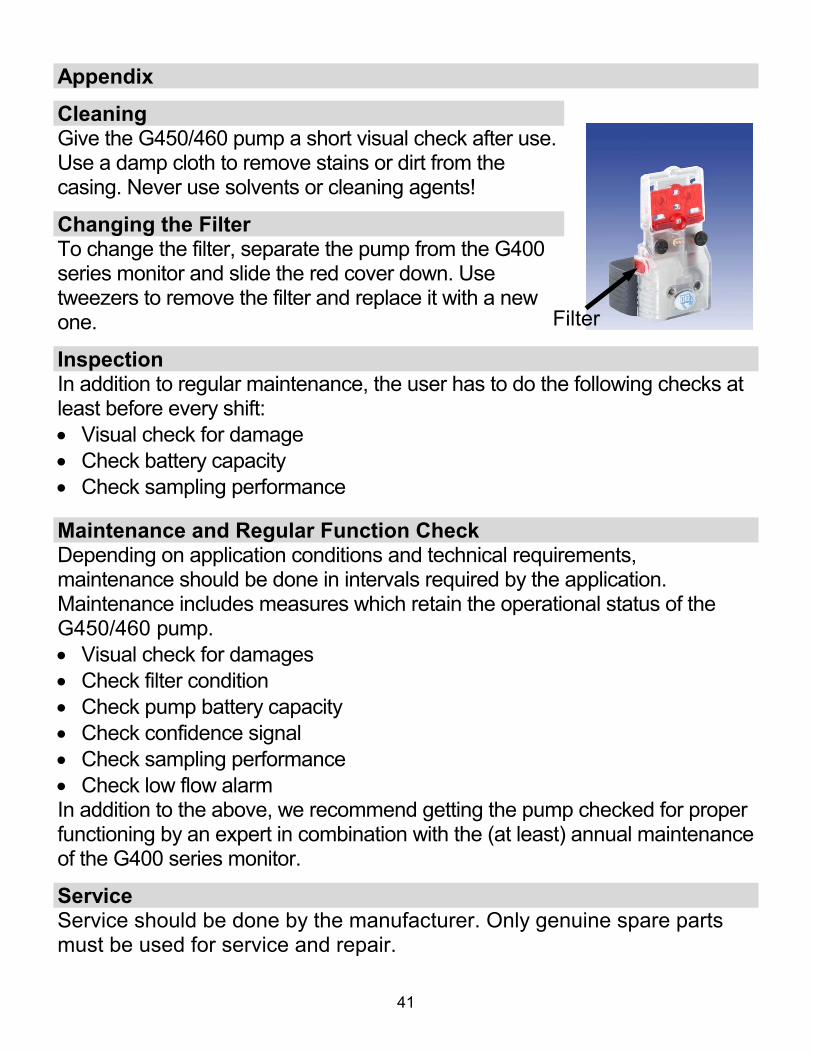
Cleaning Give the G450/460 pump a short visual check after use. Use a damp cloth to remove stains or dirt from the casing. Never use solvents or cleaning agents!
Changing the Filter To change the filter, separate the pump from the G400 series monitor and slide the red cover down. Use tweezers to remove the filter and replace it with a new one.
Inspection In addition to regular maintenance, the user has to do the following checks at least before every shift: • Visual check for damage • Check battery capacity • Check sampling performance
Maintenance and Regular Function Check Depending on application conditions and technical requirements, maintenance should be done in intervals required by the application. Maintenance includes measures which retain the operational status of the G450/460 pump. • Visual check for damages • Check filter condition • Check pump battery capacity • Check confidence signal • Check sampling performance • Check low flow alarm In addition to the above, we recommend getting the pump checked for proper functioning by an expert in combination with the (at least) annual maintenance of the G400 series monitor.
Service Service should be done by the manufacturer. Only genuine spare parts must be used for service and repair.
Filter
42
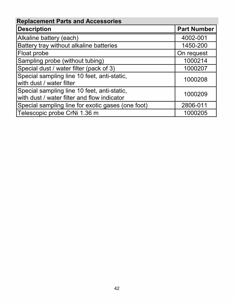
Replacement Parts and Accessories Description Part NumberAlkaline battery (each) 4002-001 Battery tray without alkaline batteries 1450-200 Float probe On request Sampling probe (without tubing) 1000214 Special dust / water filter (pack of 3) 1000207 Special sampling line 10 feet, anti-static, with dust / water filter 1000208
Special sampling line 10 feet, anti-static, with dust / water filter and flow indicator 1000209
Special sampling line for exotic gases (one foot) 2806-011 Telescopic probe CrNi 1.36 m 1000205

43
Technical Data Type: G450/460 Motorized Pump Pump performance:
0.50 lpm for 0 mm water column 0.35 lpm for 300 mm water column Maximum 100 m hose length (depending on gas and hose)
Gas supply: Sampling inlet during pump mode or diffusion inlet Indication and Alarm:
Green LED: Indication of battery capacity and confidence signal Battery alarm Red LED: Low flow alarm and system fault
Power supply: Alkaline battery module (grey casing), non-rechargeable with 2x Mignon 1.5 V type DURACELL PROCELL MN1500 LR6 AA
Operational time: Approximately 10 hours
Climate Condition: For operation: -4 to 131°F (-20 to +55°C) / 5 to 95% r. h.
For storage: -13 to 131°F (-25 to +55°C) / 5 to 95% r. h. (recommended: 32 to 86°F (0 to +30°C))
Casing: Material: Rubberized compound
Dimensions: 4.29x2.68x.83 inches (109x68x21 mm) (HxWxD) Weight: 6.35 ounces (180 g) with alkaline battery module
Protection: IP 40 Firmware Version 2.00

1194 Oak Valley Drive, Suite 20Ann Arbor, Michigan 48108 USA
Phone: (800) 959-0329 or (734) 769-0573Fax: (734) 769-1888
E-mail: [email protected]: www.gfg-inc.com
GfG reserves the right to change part numbers, prices, and/or technical information without notice. 7004-450 102407