Manual for TFAH-ES70/80/50 and TFAH-ES70/80 · User’s Manual for ION-B Systems ... networks,...
41
Page 1 Manual for TFAH-ES70/80/50 and TFAH-ES70/80 MN024-15
Transcript of Manual for TFAH-ES70/80/50 and TFAH-ES70/80 · User’s Manual for ION-B Systems ... networks,...

Page 1
Manual
for TFAH-ES70/80/50
and TFAH-ES70/80
MN024-15

User’s Manual for ION-B Systems
Page 2 Manual TFAH-ES70_80_50.doc
DISCLAIMER:
This document has been developed by CommScope, and is intended for the use of its customers and customer support personnel. The information in this document is subject to change without notice. While every effort has been made to eliminate errors, CommScope disclaims liability for any difficulties arising from the interpretation of the information contained herein. The information contained herein does not claim to cover all details or variations in equipment, nor to provide for every possible incident to be met in connection with installation, operation, or maintenance. This document describes the performance of the product under the defined operational conditions and does not cover the performance under adverse or disturbed conditions. Should further information be desired, or should particular problems arise which are not covered sufficiently for the purchaser’s purposes, contact CommScope.
CommScope reserves the right to change all hardware and software characteristics without notice.
COPYRIGHT:
© Copyright 2015 CommScope Inc. All Rights Reserved.
This document is protected by copyright. No part of this document may be reproduced, stored in a retrieval system, or transmitted, in any form or by any means, electronic, mechanical photocopying, recording, or otherwise without the prior written permission of CommScope.
TRADEMARKS
All trademarks identified by ® or ™ are registered trademarks or trademarks, respectively, of CommScope. Names of products mentioned herein are used for identification purposes only and may be trademarks and / or registered trademarks of their respective companies.
Andrew Wireless Systems GmbH, 02-April-2015

Page 3
TABLE OF CONTENTS 1.1. About CommScope 4
1.2. International Contact Addresses for Customer Support 5
2. GENERAL INTRODUCTION OF ION-B PRODUCTS 7
2.1. THE FEATURES 7
2.2. BRIEF DESCRIPTION OF ION-B 7
2.3. ION-B FEATURES 8
2.4. TYPICAL ION-B APPLICATIONS 9
2.5. THE ION-B REMOTE UNIT AND ITS RELEVANT ACCESSORIES 10
3. TFAH-ES70/80/50 & TFAH-ES70/80 11
3.1. Case U Remote Unit 11 3.1.1. Specifications 11 3.1.2. Health and Safety 14 3.1.3. TFAx Case U Mechanical Installation 17 3.1.4. Wall Mounting Procedure 20 3.1.5. TFAx Case U Electrical Installation 23
3.1.5.1. General 23 3.1.5.2. Grounding (Earthing) 25 3.1.5.3. Mains Power Connection 26 3.1.5.4. Antenna Connection 29 3.1.5.5. Alarm Ports 30
3.2. Low Power RU Optical Installation 31 3.2.1. Optical-Fiber-Cable Connection - Rules 31 3.2.2. Optical cable installation 33 3.2.3. RU Power Supply Replacement 36
4. TECHNICAL SUPPORT 40
4.1. Contact Addresses 40
4.2. Returning Equipment 41

User’s Manual for ION-B Systems
Page 4 Manual TFAH-ES70_80_50.doc
1.1. ABOUT COMMSCOPE CommScope is the foremost supplier of one-stop, end-to-end radio frequency (RF) solutions. Part of the CommScope portfolio are complete solutions for wireless infrastructure from top-of-the-tower base station antennas to cable systems and cabinets, RF site solutions, signal distribution, and network optimization. CommScope has global engineering and manufacturing facilities. In addition, it maintains field engineering offices throughout the world. Andrew Wireless Systems GmbH based in Buchdorf/ Germany, which is part of CommScope, is a leading manufacturer of coverage equipment for mobile radio networks, specializing in high performance, RF and optical repeaters. Our optical distributed networks and RF repeater systems provide coverage and capacity solution for wireless networks in both indoor installations and outdoor environments, e.g. tunnels, subways, in-trains, airport buildings, stadiums, skyscrapers, shopping malls, hotels and conference rooms. Andrew Wireless Systems GmbH operates a quality management system in compliance with the requirements of ISO 9001 and TL 9000. All equipment is manufactured using highly reliable material. To maintain highest quality of the products, comprehensive quality monitoring is conducted at all fabrication stages. Finished products leave the factory only after a thorough final acceptance test, accompanied by a test certificate guaranteeing optimal operation. This product meets the requirements of the R&TTE directive and the Declaration of Conformity (DoC) itself. A current version of the CE DoC is included in this manual CD delivered *. Any updated version of the DoC is available upon request from the local sales offices or directly from CommScope via the local Customer Support at one of the addresses listed in the following chapter. According to the DoC, our "CE"-marked equipment can be used in all member states of the European Union.
F Note: Exceptions of and national deviations from this intended use may be possible. To observe corresponding local particularities and regulations, please refer to the respective documents (also in national language) which are included in the manual CD delivered.
* In case the Declaration of Conformity (DoC) for the product was not included in the manual CD
delivered, it is available upon request from the local sales offices or directly from CommScope at one of the addresses listed in the following chapter.
To make the most of this product, we recommend you carefully read the instructions in this manual and commission the system only according to these instructions. For technical assistance and support, please also contact the local office or CommScope directly at one of the addresses listed in the following chapter.

User’s Manual for ION-B Systems
Page 5
1.2. INTERNATIONAL CONTACT ADDRESSES FOR CUSTOMER SUPPORT
Canada
AMER ICAS
United States CommScope Canada Andrew LLC, A CommScope Company
Mail 505 Consumers Road, Suite 803 Toronto M2J 4V8, Canada Mail 620 North Greenfield Parkway
Garner, NC 27529, U.S.A.
Phone +1-905-878-3457 (Office) +1-416-721-5058 (Cell) Phone +1-888-297-6433
Fax +1-905-878-3297 Fax +1-919-329-8950 E-mail [email protected] E-mail [email protected]
Caribbean & South American Region Caribbean & Central American Region CommScope Cabos do Brasil Ltda. CommScope Mexico S.A. de C.V.
CALA Tech Support for Distributed Coverage & Capacity Solutions (DCCS) products: Rua Guaporanga, 49 Praça Seca – Rio de Janeiro – RJ ZIP: 21320-180, Brazil
CALA Tech Support for Distributed Coverage & Capacity Solutions (DCCS) products: Av. Insurgentes Sur 688, Piso 6 Col. Del Valle, CP: 03100 Mexico City, Mexico
Phone +1-815-546-7154 (Cell) +55-15-9104-7722 (Office) Phone +52-55-1346-1900 (Office)
Fax + 55-15-2102-4001 Fax +52-55-1346-1901 E-mail [email protected] E-mail [email protected]
China, India and Rest of Asia
APAC
Australia & New Zealand Andrew International Corporation Andrew Corporation (Australia) Pty Ltd.
Room 915, 9/F Chevalier Commercial Centre 8 Wang Hoi Rd Kowloon Bay, Hong Kong
Unit 1 153 Barry Road Campbellfield VIC 3061, Australia
Phone +852-3106-6100 Phone +613-9300-7969 Fax +852-2751-7800 Fax +613-9357-9110 E-mail [email protected] E-mail [email protected]
Middle East & North Africa
Africa &
Middle East
South Africa CommScope Solutions International Inc.
(Branch) Andrew Wireless Solutions Africa
(PTY) LTD
PO Box 48 78 22 Unit 3206, Floor 32, Jumeirah Business Center 5, Jumeirah Lakes Towers, Dubai, United Arab Emirates
11 Commerce Crescent West Eastgate, Sandton PO Box 786117 Sandton 2146 South Africa
Phone +971 4 390 09 80 Phone + 27 11-719-6000 Fax +971 4 390 86 23 Fax + 27 11-444-5393 E-mail [email protected] E-mail [email protected]

User’s Manual for ION-B Systems
Page 6 Manual TFAH-ES70_80_50.doc
United Kingdom
EUROPE
Scandinavia Andrew Wireless Systems UK Ltd Andrew Norway (AMNW)
Unit 15, Ilex Building Mulberry Business Park Fishponds Road Wokingham Berkshire RG41 2GY, England
P.O. Box 3066 Osloveien 10 Hoenefoss 3501 Norway
Phone +44-1189-366-792 Phone + 47 32-12-3530 Fax +44-1189-366-773 Fax + 47 32-12-3531 E-mail [email protected] E-mail [email protected]
Germany France Andrew Wireless Systems GmbH CommScope France
Mail Industriering 10 86675 Buchdorf Germany
Mail Immeuble Le Lavoisier 4, Place des Vosges 92052 Courbevoie, France
Phone +49-9099-69-0 Phone +33-1 82 97 04 00 Fax +49-9099-69-930 Fax +33-1 47 89 45 25 E-mail [email protected] E-mail [email protected]
Austria Switzerland Andrew Wireless Systems (Austria) GmbH CommScope Wireless Systems AG
Mail Weglgasse 10 2320 Wien-Schwechat Austria
Mail Tiergartenweg 1 CH-4710 Balsthal Switzerland
Phone +43-1706-39-99-10 Phone +41-62-386-1260 Fax +43-1706-39-99-9 Fax +41-62-386-1261 E-mail [email protected] E-mail [email protected]
Italy Iberia Region - Spain & Portugal CommScope Italy S.r.l., Faenza, Italy Andrew España S.A. A CommScope Company
Mail Via Mengolina, 20 48018 Faenza (RA) Italy
Mail Avda. de Europa, 4 - 2ª pta. Parque Empresarial de la Moraleja Alcobendas, Madrid 28108, Spain
Phone +39-0546-697111 Phone +34-91-745-20 40 Fax +39-0546-682768 Fax +34-91-661-87 02 E-mail [email protected] E-mail [email protected]
Czech Republic
CommScope Solutions Czech Republic
C-Com, spol. s r.o
Mail U Moruší 888 53006 Pardubice, Czech Republic
Phone +49 871 9659171 (Office) +49 171 4001166 (Mobile)
Fax +49 871 9659172 E-mail [email protected]

User’s Manual for ION-B Systems
Page 7
2. GENERAL INTRODUCTION OF ION-B PRODUCTS
2.1. THE FEATURES ION-B is an innovative platform designed in order to provide an effective and flexible coverage to a large variety of indoor scenarios. Thanks to its high modularity, its low power consumption, and its full-transparency to protocols and modulation formats, ION-B is the perfect plug&play solution to distribute any wireless standard (including GSM, GPRS, EDGE, CDMA, W-CDMA, and LTE to the in-building environments requiring reliable and interference-free communications, as well as high traffic capacity and maximum flexibility about future expansions. These unique features make the ION-B platform suitable also for applications to critical areas experiencing difficulties in establishing and keeping phone calls, while its compact design always guarantees a minimum aesthetic impact.
2.2. BRIEF DESCRIPTION OF ION-B ION-B is a Distributed Antenna System (DAS) based on the Radio-over-Fibre (RoF) technology, and capable of carrying wireless mobile signals through the 700MHz - 2700MHz frequency range regardless of their protocol and their modulation format. The system has two basic components, a Master Unit and a Remote Unit. The Master Unit is made of one or more subracks typically connected to the BTS (Base Transceiver Station) through either a repeater (RF interface) or a coaxial cable. Each Remote Unit is connected with a dedicated pair of single-mode optical fibres (one for UL and one for DL) to the Master Unit. These optical fibres work on 1310 nm wavelength and provide low losses and almost unlimited bandwidth, available for future system developments.
ION-B System Block Diagram
ION-B is a modular system whose basic components are: · one Master Unit made of one or more subracks, each providing 12 module slots.
Each slot can host either an active or a RF passive device (chosen among the wide range of ION-B options), in order to meet the planned design requirements;
· a variable number of Remote Units (TFAx), whose function is feeding the antenna passive network;
· a proper number of indoor antennas, suitable to provide radio coverage to the area. ION-B is fully compatible with any type of indoor antennas;
· the optical cables required to connect the 19” subracks to the TFAx.
User’s Manual for ION-B Systems
Page 8 Manual TFAH-ES70_80_50.doc
2.3. ION-B FEATURES The following lines report a brief summary of ION-B main features: · multiband 2G, 2.5G, 3G, and 4G compatible: ION-B is completely transparent to
any transmission protocol and modulation format, and it can distribute any 2G, 2.5G, 3G, and 4G wireless standard. In addition, it allows to carry also the WLAN (802.11b/g) service over the same infrastructure;
· modular configuration for flexible design: by properly setting some parameters like
the amount of RUs and the antenna locations, the ION-B architecture can follow the environment specific features in order to obtain the most effective radio coverage of the indoor area. The modularity of the system allows easy modifications for future growth and increasing traffic;
· easy to install: the intelligent plug & play ION-B system includes an Automatic
Gain Control (AGC), that eliminates system gain variations regardless of optical loss. This avoids the need for field adjustments, thus reducing design, installation and optimization time.
· low-power consumption: establishing a “quasi line-of-sight propagation” towards
all mobile phones inside the area, ION-B works with low power levels. Low power levels have two great advantages: 1) allow mobile phones to work at lower power levels, thus limiting the radiated emissions and increasing their battery life; 2) allow a better control of interference effects between adjacent cells.
· central supervision functions: all individual alarms of ION-B system are available
to both local and remote connections. Detailed alarm information is provided by special software (i.e. by Supervision or Maintenance software tools) running on a locally connected host, as well as any information about alarm status and alarm history is available to remote connections via TCP/IP protocols, SNMP agent, or HTTP servers. This alarm information is visible also by means of LEDs present on the front panels of both the MU and the RUs;
· multiple-carriers system: there are no restrictions on the number of carriers that
the ION-B can convey. Obviously, the more carriers per service, the less power per carrier;
· remote power supply: in case mains cannot be used for the Remote Units, ION-B
offers a centralised power supply option, which distributes both a DC low-voltage (-48V) power and the optical signals through a composite fibre optic/copper cable;
· wide variety of RF passive devices: the connections between the DAS and the
local BTSs are able to be arranged so as to get the best fit for the customers needs. ION-B equipment provides RF splitters/combiners, cross band couplers, attenuators, and duplexers for UL/DL paths, thus allowing maximum in design flexibility;
· high reliability: high MTBF (Mean Time Between Failure).

User’s Manual for ION-B Systems
Page 9
2.4. TYPICAL ION-B APPLICATIONS Due to its unique features, the ION-B is an ideal solution for radio coverage in a variety of situations: Multi-operator shared infrastructures: each mobile operator has its own carrier which needs to be transported without interfering with the others. The ION-B is capable of transmitting multiple carriers simultaneously while providing independent level adjustments for each of them, ensuring maximum performance and reducing infrastructure costs. High rise buildings: RF signals from surrounding macro cells or external BTSs are usually quite strong inside high rise buildings and can cause so much interference that indoor mobile communications often become impossible. By strategically placing antennas along the exterior walls of the building, the signal to noise ratio can be optimized. This interference control solves many problems, such as the “ping pong” effect that sometimes is experienced when a mobile frequently changes from indoor to outdoor coverage. Exhibitions, conventions, and shopping centers: the critical aspect of these environments is their high traffic loads, which are furthermore also highly variable. Thus, the main goal in these cases is to set up radio coverage enabling the effective management of these variable traffic loads, with neither undervalued nor overvalued infrastructure expenses. A unique feature of the ION-B is that RF frequencies can be allocated quickly when and where they are needed, thus reducing implementation costs. This makes the ION-B an ideal solution for temporary or last minute requests (such as conferences). Airports: require both modular and flexible radio coverage in order to meet their current needs while also foreseeing future expansions. The ION-B is able to manage heavy traffic loads, providing a high level of quality with minimum environmental impacts, its modularity also allows for future expansions. Corporate buildings: inside a corporate building, frequent disruptions during mobile communications may limit business transactions. These environments are often complex and densely populated while having specific requirements: heavy traffic capacity, high expectations regarding quality of service, full compatibility with wireless standards and future expandability. The ION-B guarantees high quality radio coverage in all of the above conditions and maintains maximum flexibility while managing any possible traffic conditions. Subways and densely populated metropolitan areas: These areas are distinguished by large surface areas, and may require RUs to be placed far away from the BTSs. The ION-B guarantees signal integrity for distances up to 3km, while through the wideband interconnect link option, distances of 20km can be reached. Moreover, these environments require gradual investments, because initially operators tend to provide radio coverage only in the busiest areas, and then extend it in order to reach complete coverage later. The modularity of the ION-B helps operators to gradually expand the system. Often, large cities set up seamless and reliable radio systems for emergency services. In these cases, the required RF infrastructure needs to be unobtrusive and environmental friendly; this can be achieved using an ION-B DAS. When redundancy is required, two interleaved ION-B systems can be used, management and supervision for these systems can be remotely established by means of an external modem and an open protocol such as SNMP.
User’s Manual for ION-B Systems
Page 10 Manual TFAH-ES70_80_50.doc
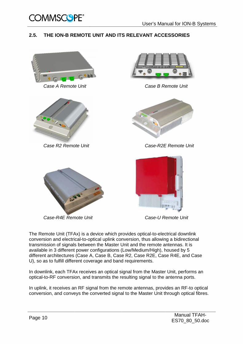
2.5. THE ION-B REMOTE UNIT AND ITS RELEVANT ACCESSORIES
Case A Remote Unit Case B Remote Unit
Case R2 Remote Unit Case-R2E Remote Unit
Case-R4E Remote Unit Case-U Remote Unit
The Remote Unit (TFAx) is a device which provides optical-to-electrical downlink conversion and electrical-to-optical uplink conversion, thus allowing a bidirectional transmission of signals between the Master Unit and the remote antennas. It is available in 3 different power configurations (Low/Medium/High), housed by 5 different architectures (Case A, Case B, Case R2, Case R2E, Case R4E, and Case U), so as to fulfill different coverage and band requirements. In downlink, each TFAx receives an optical signal from the Master Unit, performs an optical-to-RF conversion, and transmits the resulting signal to the antenna ports. In uplink, it receives an RF signal from the remote antennas, provides an RF-to optical conversion, and conveys the converted signal to the Master Unit through optical fibres.

User’s Manual for ION-B Systems
Page 11
The ION-B Remote Units are available both with power supply 90÷264 Vac and with power supply -60÷-36 Vdc. Each ION-B Remote Unit is provided with a suitable internal or external power adapter. Last, each ION-B Remote Unit has a wideband auxiliary channel, which can be exploited for dedicated RF distribution through external boosters.
3. TFAH-ES70/80/50 & TFAH-ES70/80
3.1. CASE U REMOTE UNIT
3.1.1. Specifications
Dimensions: mm 500 x 480 x 205
(inches 19.7 x 18.9 x 8.1)
Weight: Please refer to the Remote Unit dedicated e-catalog entry in order to know the updated data about the weight of your Case U Remote Unit.
Case U Remote Unit
Case U Remote Units are available with and without the red cover, which serves for indication of public safety services equipment.

User’s Manual for ION-B Systems
Page 12 Manual TFAH-ES70_80_50.doc
Case U connectors
A Status LED G Power supply connector B Alarms lower band H Grounding bolts C Alarms higher band(s) I UL/DL antenna port higher band(s) D Expansion UL port J UL lower band, not connected in 2 band E Expansion DL port K DL lower band, not connected in 2 band F UL / DL optical ports
Antenna Port In the two band configuration the RU has one duplexed N-female antenna port for transmitting and receiving signals to and from distributed antennas. In the three band configuration the RU also has two non-duplexed N-female antenna ports and for UL and DL. These RF ports can be connected directly to an antenna (i.e. using RF jumper cables) or through splitters, allowing additional antennas to be fed by the RU.
Status LED The status LED provides a visual warning of an alarm condition. The color of the LED indicates the severity of the alarm.
Expansion Ports The Expansion UL and Expansion DL ports are QMA female connectors that are used to connect to a CommScope expansion unit to provide additional bands.
K J
F D
I
A
B C D E
H G I J
F
K
User’s Manual for ION-B Systems
Page 13
Optical Ports The LC-APC optical connectors are used to send and receive the signals between the RU and the Master Unit’s OTRx modules.
· A DL optical port receives downlink signals from the MU OTRx. · A UL optical port transmits uplink signals to the MU OTRx.
Mains Connector The RU receives its power through the Mains connector . The type of connector is dependent on the RU model. A 4-pin Amphenol connector is used for AC models and standard DC models. A 7-pin Amphenol connector is used for DC models powered by a dual cable supply.
Alarm connectors The RU has two alarm relay outputs that can be used report alarms to external devices. The Alarm connectors , lower band and , higher bands are 5-pin Binder connectors.
C
F
B
G

User’s Manual for ION-B Systems
Page 14 Manual TFAH-ES70_80_50.doc
3.1.2. Health and Safety 1. Danger: Obey all general and regional installation and safety regulations relating
to work on high voltage installations, as well as regulations covering correct use of tools and personal protective equipment.
2. Danger: Before opening the unit, disconnect mains power.
3. Danger: Laser radiation! Do not stare into the beam; do not view it directly or with optical instruments.
4. Danger: Due to power dissipation, the Remote Unit may reach a very high temperature. Do not operate this equipment on or close to flammable materials. Use caution when servicing the unit.
5. Warning: Read and obey all the warning labels attached to the unit. Make sure that all warning labels are kept in a legible condition. Replace any missing or damaged labels.
6. Warning: It is the responsibility of the network provider to implement prevention measures to avoid health hazards associated with radiation from the antenna(s) connected to the unit.
7. Warning: Only authorized and trained personnel are allowed to open the unit and get access to the inside.
8. Warning: Only license holders for the respective frequency range are allowed to operate this unit.
9. Warning: Make sure the repeater settings are correct for the intended use (refer to the manufacturer product information) and regulatory requirements are met.
10. Warning: Use this equipment only for the purpose specified by the manufacturer. Do not carry out any modifications or fit any spare parts, which are not sold or recommended by the manufacturer. This could cause fires, electric shock, or other injuries.
11. Warning: For installations which have to comply with European EN50385 exposure compliance requirements, the following Power Density limits/guidelines (mW/cm²) according to ICNIRP are valid:
o 0.2 for frequencies from 10 MHz to 400 MHz o F (MHz) / 2000 for frequencies from 400 MHz to 2 GHz o 1 for frequencies from 2 GHz to 300 GHz

User’s Manual for ION-B Systems
Page 15
12. Warning: For installations, which have to comply with FCC RF exposure requirements, the antenna selection and installation must be completed in a way to ensure compliance with those FCC requirements. Depending on the RF frequency, rated output power, antenna gain, and the loss between the repeater and antenna, the minimum distance D to be maintained between the antenna location and human beings is calculated according to this formula:
where
· P (mW) is the radiated power at the antenna, i.e. the max. rated repeater output power in addition to the antenna gain minus the loss between the repeater and the antenna.
· PD (mW/cm²) is the allowed Power Density limit acc. to 47 CFR 1.1310 (B) for general population / uncontrolled exposures which is
o F (MHz) / 1500 for frequencies from 300MHz to 1500MHz o 1 for frequencies from 1500MHz to 100.000MHz
RF exposure compliance may need to be addressed at the time of licensing, as required by the responsible FCC Bureau(s), including antenna co-location requirements of 1.1307(b)(3).
13. Caution: Installation of this equipment is in full responsibility of the installer, who has also the responsibility, that cables and couplers are calculated into the maximum gain of the antennas, so that this value, which is filed in the FCC Grant and can be requested from the FCC data base, is not exceeded. The industrial boosters are shipped only as a naked booster without any installation devices or antennas as it needs for professional installation.
14. Caution: Only suitably qualified personnel are allowed to work on this unit and only after becoming familiar with all safety notices, installation, operation and maintenance procedures contained in this manual.
15. Caution: Keep operating instructions within easy reach and make them available to all users.
16. Caution: Corresponding local particularities and regulations must be observed. For national deviations, please refer to the respective documents included in the manual CD that is delivered with the unit.
17. Caution: Although the Remote Unit is internally protected against overvoltage, it is strongly recommended to ground (earth) the antenna cables close to the repeater’s antenna connectors for protection against atmospheric discharge.
18. Caution: ESD precautions must be observed! Before commencing maintenance work, use the available grounding (earthing) system to connect ESD protection measures.

User’s Manual for ION-B Systems
Page 16 Manual TFAH-ES70_80_50.doc
19. Note: For a Class A digital device or peripheral: This equipment has been tested and found to comply with the limits for a Class A digital device, pursuant to part 15 of the FCC Rules. These limits are designed to provide reasonable protection against harmful interference when the equipment is operated in a commercial environment. This equipment generates, uses, and can radiate radio frequency energy and, if not installed and used in accordance with the instruction manual, may cause harmful interference to radio communications. Operation of this equipment in a residential area is likely to cause harmful interference in which case the user will be required to correct the interference at his own expense.
20. Note: This unit complies with European standard EN60950.
Equipment Symbols Used / Compliance Please observe the meanings of the following symbols used in our equipment and the compliance warnings:
Symbol Compliance Meaning / Warning
--- FCC
For industrial (Part 20) signal booster: WARNING: This is NOT a CONSUMER device. It is designed for installation by FCC LICENSEES and QUALIFIED INSTALLERS. You MUST have an FCC LICENSE or express consent of an FCC Licensee to operate this device. Unauthorized use may result in significant forfeiture penalties, including penalties in excess of $100,000 for each continuing violation. For (Part 90) signal booster:
CE
Alert sign to R&TTE To be sold exclusively to mobile operators or authorized installers – no harmonized frequency bands, operation requires license. Intended use: EU and EFTA countries
Indicates conformity with the R&TTE directive 1999/5/EC certified by the notified body no. 0700.

User’s Manual for ION-B Systems
Page 17
3.1.3. TFAx Case U Mechanical Installation
Each Case U Remote Unit kit includes:
1. a RU TFAx
2. a power supply plug
1. Warning: Do not install the unit in a way or at a place where the specifications
outlined in the Environmental and Safety Specifications leaflet of the supplier are not met.
2. WARNING: IMPROPER INSTALLATION CAN LEAD TO EQUIPMENT FALLING CAUSING SERIOUS PERSONAL INJURY OR DAMAGE TO EQUIPMENT. The installer must verify that the supporting surface will safely support the combined load of the electronic equipment and all attached hardware and components. The screws and dowels (wall anchors) used should also be appropriate for the structure of the supporting wall.
3. Warning: It is recommended to use the mounting hardware delivered by the manufacturer only. If different mounting hardware is used, the specifications for stationary use of the Remote Unit must not be exceeded.
4. F Note: Exceeding the specified load limits may cause the loss of warranty!
5. Warning: The unit is considerably heavy. Ensure there is adequate manpower to handle the weight of the system.
6. Caution: Due to power dissipation, the Remote Unit may reach a very high temperature. Ensure sufficient airflow for ventilation.
7. Attention: This device is for indoor use only. 8. Note: When connecting and mounting the cables (RF, optical, mains, ...) ensure
that no water can penetrate into the unit through these cables. 9. Note: Observe all additional rules or restrictions regarding mounting that apply to
specific Remote Unit types.
If any different or additional mounting material is used, ensure that the mounting remains as safe as the mounting designed by the manufacturer. Ensure that the static and dynamic strengths are adequate for the environmental conditions of the site. The mounting itself must not vibrate, swing or move in any way that might cause damage to the Remote Unit.
Specified torques must be observed for certain mounting procedures according to the following table:
Type Pins Hex nuts Screws Thread M 6 M 6 M6 Specified torques 3.3 Nm 3.3 Nm 3.3 Nm
Specified torques

User’s Manual for ION-B Systems
Page 18 Manual TFAH-ES70_80_50.doc
Wall-Mounting
1. Check the suitability of the wall-mounting kit and the wall.
2. Install the wall-mounting bracket using 4 M6 screw anchors (not included*) or suitable lag bolts according to the drilling layout. Confirm that the bracket is securely fastened to the wall. Installer must verify that the supporting surface will safely support the combined load of the electronic equipment and all attached hardware and components.
* The M6 screw anchors are not included as part of the RU delivery because the suitable type depends on the on-site conditions (wall structure and materials). Use screw anchors that are appropriate for the mounting surface.
Wall-mounting bracket

User’s Manual for ION-B Systems
Page 19
3. Attach an M6 threaded pin to the Remote Unit by inserting it into the threaded
hole adjacent to the power supply and turning it clockwise. Tighten the pin securely with a socket wrench.
RU threaded pin power supply side
4. Attach an M6 threaded pin to the Remote Unit by inserting it into the threaded hole above the handle and turning it clockwise. Tighten the pin securely with a socket wrench.
RU threaded pin narrow side

User’s Manual for ION-B Systems
Page 20 Manual TFAH-ES70_80_50.doc
3.1.4. Wall Mounting Procedure
1. Follow the instructions for mounting the bracket and installing the threaded pins.
2. Install the Remote Unit on the wall-mounting bracket by lifting the RU into place and using both handles and lowering it down onto the bracket. The M6 pins must align with the slots in the bracket to support the RU.
Place RU onto wall mounting bracket

User’s Manual for ION-B Systems
Page 21
3. Fasten the lower section of the Remote Unit to the bracket using a washer
and an M6x12 screw (on both sides). Slide a washer over each screw and then insert the screw and tighten it securely.
Install M6x12 screws and washers for single mount
4. Fasten the Remote Unit to the bracket using a washer and M6 nut. Slide the washer over the threaded pins that you installed previously and then screw the nut onto the pins (on both sides) and tighten securely.
Attach M6 nut to threaded pins for single mount

User’s Manual for ION-B Systems
Page 22 Manual TFAH-ES70_80_50.doc
5. Confirm that all screws and nuts have been fastened and the unit is securely
mounted to the wall.
Completed RU Mount

User’s Manual for ION-B Systems
Page 23
3.1.5. TFAx Case U Electrical Installation
3.1.5.1. General 1. Warning: This unit contains dangerous voltages. Loss of life, severe personal
injury, or property damage can be the result if the instructions contained in this manual are not followed.
2. Caution: It is compulsory to ground (earth) the unit before connecting the power supply. A grounding bolt is provided on the cabinet to connect the ground-bonding cable.
3. Caution: Although the remote unit is internally protected against overvoltage, it is strongly recommended to ground (earth) the antenna cables close to the antenna connectors of the remote unit for protection against atmospheric discharge. In areas with strong lightning, it is strongly recommended to install additional lightning protection.
4. Caution: If the mains connector of the remote unit is not easily accessible, a disconnect device in the mains power circuit must be provided within easy reach.
5. Caution: Before connecting or disconnecting the mains connector at the remote unit, ensure that mains power supply is disconnected.
6. Caution: Make sure that an appropriate circuit breaker acting as a disconnect device (as required by IEC/EN60950-1) and an overcurrent limiting device are connected between mains power and the Remote Unit.
7. Caution: A connection of the mains supply to a power socket requires the power socket to be nearby the remote unit.
8. Caution: Incorrectly wired connections can destroy electrical and electronic components.
9. Caution: To avoid corrosion at the connectors caused by electrochemical processes, the material of the cable connectors must not cause a higher potential difference than 0.6 V (see electrochemical contact series).
10. Note: Use an appropriate torque wrench for the coupling torque of N-type connectors (2 Nm / 1.5 lb/ft), with 13/16 in opening to tighten the N-type antenna connectors. For example, use torque wrench of item no. 244379 available from the CommScope e-catalog. Do NOT use your hands or any other tool (e.g. a pair of pliers)! This might cause damage to the connector and lead to a malfunction of the Remote Unit.
11. Caution: For unstabilized electric networks, which frequently generate spikes, the use of a voltage limiting device is advised.

User’s Manual for ION-B Systems
Page 24 Manual TFAH-ES70_80_50.doc
12. Caution: The unit complies with the surge requirement according to EN 61000-4-5 (fine protection); however, installation of an additional medium (via local supply connection) and/or coarse protection (external surge protection) is recommended depending on the individual application in order to avoid damage caused by overcurrent.
13. Caution: Observe the labels on the front panels before connecting or disconnecting any cables.
14. Caution: Take care for Class B applications not to exceed the max.radiated outputpower of 5W (erp).
For example: The maximum measured RF Power out is 31 dBm per channel, so the maximum antenna gain (x) can be calculated as follow: Limit = 5 W (erp) = 37 dBm 37 dBm > 31 dBm + x ------> x = 37 dBm – 31 dBm = 6 dBd x dBi = 6 dBd + 2.15 = 8.15 dBi The antenna and cable, that will be used for the complete system, should have a gain lower than 8.15 dBi, relative to a dipol. The antenna gain was calculated by a cable loss of 0dB.
1 channel with 31dBm 8.15 dBi 2 channel with 28 dBm 11.15 dBi 4 channel with 25 dBm 14.15 dBi
If the cable has a loss of 2dB => the gain of the antenna must be lower than 10.15 dBi
1 channel with 31dBm 10.15 dBi 2 channel with 28 dBm 13.15 dBi 4 channel with 25 dBm 16.15 dBi

User’s Manual for ION-B Systems
Page 25
3.1.5.2. Grounding (Earthing) The RU must be grounded (earthed). 1. Connect an earth-bonding cable to the grounding bolt(s) connection provided on
the outside of the remote unit (near the Mains connector). Do not use the grounding connection to connect external devices.
Grounding bolts Grounding bolt, schematic view
2. After loosening the hex nut, connect the earth-bonding cable between the two washers as illustrated in the figures above.
3. Then, fasten all parts again by tightening the hex nut.
4. Connect the other end of the ground wire to a suitable permanent ground following local electrical code practices.

User’s Manual for ION-B Systems
Page 26 Manual TFAH-ES70_80_50.doc
3.1.5.3. Mains Power Connection Before connecting electrical power to the units, the system must be grounded (earthed) as described in the previous chapter. The Mains power must be connected to the Mains connector of the unit for operation of the RU. A power cable is delivered with each RU. The type of power cable delivered is dependent on the type of power supply in the RU. The AC power cable is a 3.2 m (10.5 ft) 16 AWG cable with a 4-pin Amphenol C016 series plug on one end to connect to the RU Mains connector. The other end of the cable is un-terminated with 3 end splices to connect to the AC power source. A 10 m (33.7 ft) AC power cable is also available as an option.
4-Pin Amphenol C016 Series
Pin Name Color 1 Phase Brown 2 Neutral Blue 3 n.c. n.c 4 Ground Yellow /
Green
AC power cable AC power cable
The standard DC power cable is a 3.2 m (10.5 ft) 13 AWG cable with a 4-pin Amphenol C016 series plug on one end to connect to the RU Mains connector. The other end of the cable is un-terminated with 2 end splices to connect to the -48 Vdc power source.
4-Pin Amphenol C016 Series
Pin Name Color 1 n.c n.c 2 –48V Black 3 0V Red 4 n.c. n.c
DC power cable DC power cable
User’s Manual for ION-B Systems
Page 27
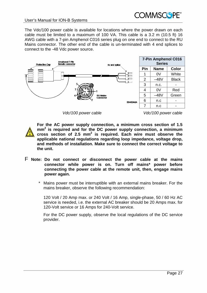
The Vdc/100 power cable is available for locations where the power drawn on each cable must be limited to a maximum of 100 VA. This cable is a 3.2 m (10.5 ft) 16 AWG cable with a 7-pin Amphenol C016 series plug on one end to connect to the RU Mains connector. The other end of the cable is un-terminated with 4 end splices to connect to the -48 Vdc power source.
7-Pin Amphenol C016 Series
Pin Name Color 1 0V White 2 –48V Black 3 n.c. - 4 0V Red 5 –48V Green 6 n.c - 7 n.c -
Vdc/100 power cable Vdc/100 power cable
For the AC power supply connection, a minimum cross section of 1.5
mm2 is required and for the DC power supply connection, a minimum cross section of 2.5 mm2 is required. Each wire must observe the applicable national regulations regarding loop impedance, voltage drop, and methods of installation. Make sure to connect the correct voltage to the unit.
F Note: Do not connect or disconnect the power cable at the mains
connector while power is on. Turn off mains* power before connecting the power cable at the remote unit, then, engage mains power again.
* Mains power must be interruptible with an external mains breaker. For the mains breaker, observe the following recommendation:
120 Volt / 20 Amp max. or 240 Volt / 16 Amp, single-phase, 50 / 60 Hz AC service is needed, i.e. the external AC breaker should be 20 Amps max. for 120-Volt service or 16 Amps for 240-Volt service.
For the DC power supply, observe the local regulations of the DC service provider.

User’s Manual for ION-B Systems
Page 28 Manual TFAH-ES70_80_50.doc
Use the following method to install and connect the Mains power to the RU:
1. Locate the Mains power cable that was delivered with the RU.
2. Locate or install a suitable power junction box or receptacle near the RU and route the power cable from the power source to the RU. Do not connect the cable to the RU’s Mains connector at this time. The power source must be interruptible.
3. The Mains cable must be properly secured observing local regulations and electrical codes. Be sure to allow enough slack in the cable at the RU to plug or unplug the cable into the Mains connector of the RU.
4. Wire the power cable to the junction box or receptacle. (Vdc/100 cable) depending on the type of power supply used by the RU.
5. With the cable’s Mains plug disconnected from the RU, turn the circuit breaker on, unscrew the plug’s protective cover, and carefully test the plug with a voltmeter to ensure that the voltage and polarity are correct.
6. Once the testing has been completed, turn off the circuit breaker.
7. Unscrew the protective cover from the Mains connector of the RU.
8. Insert the plug into the Mains connector and tighten the clamping ring until it is hand tight. Do not over-tighten the clamping ring.
Connect Mains plug
Clamping ring
Mains plug
Mains connector

User’s Manual for ION-B Systems
Page 29
3.1.5.4. Antenna Connection The Remote Unit has one N-type antenna connector(s). For mounting the cable connector, it is recommended to refer to the corresponding documentation of the connector manufacturer. The bending radius of the antenna cables must remain within the given specifications. The selection of cable and antenna is an important consideration. On the one hand, a cable with higher loss is less expensive but, on the other hand, it impairs performance.
Use an appropriate torque wrench for the coupling torque of N-type connectors (2 N-m / 1.5 lb/ft), with 13/16 in opening to tighten the N-type antenna connectors. For example, use torque wrench of item no. 244379 available from the CommScope e-catalog. Do NOT use your hands or any other tool (e.g. a pair of pliers)! This might cause damage to the connector and lead to a malfunction of the Remote Unit.
To minimize passive inter-modulation (PIM) distortion, attention must be paid to the physical condition of the connector junctions. Do not use connectors that show signs of corrosion on the metal surface. Prevent the ingress of water into the connector. Attach and torque the connectors properly.
1. Route the antenna cable from the antenna or splitter to the base of the RU. 2. Cut the cable to length and terminate the cable with an N-type male connector. 3. Remove the red plastic protective cover from the N-type female connector. 4. Using an appropriate torque wrench, connect the cable to the antenna port of
the RU.
N-type antenna connector
Antenna cable
User’s Manual for ION-B Systems
Page 30 Manual TFAH-ES70_80_50.doc
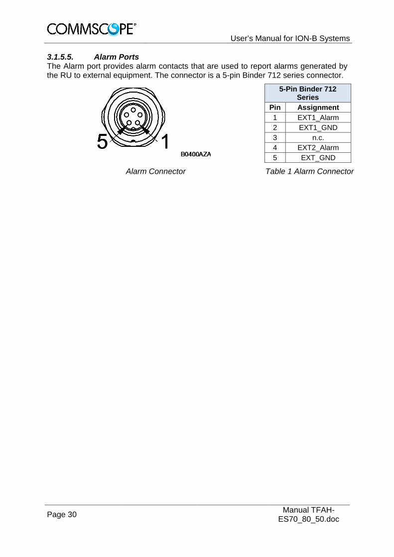
3.1.5.5. Alarm Ports The Alarm port provides alarm contacts that are used to report alarms generated by the RU to external equipment. The connector is a 5-pin Binder 712 series connector.
5-Pin Binder 712 Series
Pin Assignment 1 EXT1_Alarm 2 EXT1_GND 3 n.c. 4 EXT2_Alarm 5 EXT_GND
Alarm Connector Table 1 Alarm Connector

User’s Manual for ION-B Systems
Page 31
3.2. LOW POWER RU OPTICAL INSTALLATION
3.2.1. Optical-Fiber-Cable Connection - Rules Main optical system parameters: Fiber:
· Single mode fiber, type is 9.5/125 µm · Fiber-cable connectors LC/APC
ION-U system: · The pigtails for the connection between Master Unit and Remote Unit must
have a sufficient length. Protection for the optical fibers must be provided where the fibers feed into the units.
· The system attenuation of the optical fibers, including the connectors, must not exceed 5 dB.
System attenuation and attenuation of optical components must be determined. This can be achieved by measuring attenuation and reflection with an appropriate measuring instrument. For pigtails, a total value of < 0.4 dB (measured to a reference plug) can be assumed due to the dead zone of the reflectometer. These measurements must be made with a sufficient length of optical fiber, at the input and output of the device which has to be measured. Fiber-System Installation: Fiber-cable connectors have to be of the same type (LC/APC) as the connectors used for the unit. The fiber-optic cables are connected to the optical transceiver. Angled connectors are not compatible with straight optical connectors;
non-compatibility of connectors will result in permanent damage to both connectors.
Before connecting the fiber cables, follow the procedure below to ensure optimized performance. It is important for these procedures to be carried out with care:
· Remove fiber-optic protective caps just before making the fiber connections. Do not leave any LC/APC connectors open as they may attract dirt. Unused optical connectors must always be covered by their caps.
· Do not bend the fiber-optic cable in a tight radius (< 5 cm) as this may cause
damage to the cable and interrupt transmission.

User’s Manual for ION-B Systems
Page 32 Manual TFAH-ES70_80_50.doc
· Using high-grade alcohol and lint-free cotton cleaning swabs, clean the end of the fiber-optic cable that will be inserted in the optical connectors on the donor interface box. Use a fiber end-face inspection tool to scan both, the class fiber and its surrounding area.
· Check for dirt on the cladding, chips/pits, dirt on the ferrule, and scratches.
· Connect the fiber-optic cables by inserting the cable end into the laser
receptacle.
· Do not use any index-matching gels or fluids of any kind in these connectors. Gels are intended for laboratory use and attract dirt in the field.
F Note: Care should be taken when connecting and disconnecting fiber-
optic cables - use the connector housing to plug or unplug a fiber. Scratches and dust significantly affect system performance and may permanently damage the connector. Always use protective caps on fiber-optic connectors not in use.
Cleaning Procedure for Fiber-Optical Components Any contamination in the fiber connection results in additional optical transmission loss which could cause whole system failure. It is thus recommended that every fiber connector be inspected and cleaned prior to mating. The goal is to eliminate any dust or contamination and to provide a clean environment for the fiber-optic connection. When you clean fiber components, always complete the following steps carefully:
1. Turn off the ION-U system (laser sources) before you inspect fiber connectors.
Never look into a fiber while the system lasers are on! 2. Check the connectors or adapters with a fiberscope before cleaning. 3. If the connector is dirty, clean it with a lint-free wipe (dry cleaning). 4. Inspect the connector. 5. If the connector is still dirty, repeat the dry cleaning technique. 6. Inspect the connector. 7. If the connector is still dirty, clean it with 99% isopropyl alcohol (wet cleaning)
followed immediately with a dry clean in order to ensure no residue is left on the surface.
8. Repeat steps 5 through 7 until surface is clean. Note: For a more detailed description, please refer to:
http://www.cisco.com/en/US/tech/tk482/tk876/technologies_white_paper09186a0080254eba.shtml

User’s Manual for ION-B Systems
Page 33
3.2.2. Optical cable installation
1. Locate the Optics connector cover on the lower right side of the RU. Loosen the four cover screws, remove the cover, and set it aside. Removing this cover allows access to the UP and DL optical connectors.
Remove optics cover
2. Remove the sealing nut from the optical cable gland at the bottom of the RU.
Remove sealing nut
Sealing nut
Cover Screws
Optical connectors

User’s Manual for ION-B Systems
Page 34 Manual TFAH-ES70_80_50.doc
3. Remove the split-seal and clamp jacket.
Split-seal and clamp jacket
4. Insert the optical cables through the sealing nut and the clamp jacket.
5. Then insert the optical cables through the opening in the cabinet.
6. Connect the optical cables to the proper UL and DL LC/APC connectors.
Optical cables connected
Split-seal
Sealing nut Clamp jacket
Connect LC/APC optical
cables

User’s Manual for ION-B Systems
Page 35
7. Separate the two halves of the split-seal. Place one cable into the hole and the other in the groove of each half of the split-seal. Insert the spit seal into the clamp jacket.
Place cables into split-seal
8. Insert the clamp jacket with split seal to the connector socket and fasten them with the sealing nut.
Optical cable installed
9. Replace the optics metal cover and tighten the four screws that were loosened in step 1.
Split-seal
Clamp jacket
Sealing nut
Connector socket

User’s Manual for ION-B Systems
Page 36 Manual TFAH-ES70_80_50.doc
3.2.3. RU Power Supply Replacement The power supply for the RU is a field replaceable module. The type of power supply used by the RU (AC, DC, or Vdc/100) is dependent on the model number of the RU. Before starting any maintenance on the RU, read the health and safety
warnings in chapter 4.2.1.
1. Switch off the circuit breaker supplying power to the RU.
2. Once you have confirmed that the power has been shutdown, remove Mains power connector from the RU.
Disconnect Mains power
3. Locate the power supply on the right side of the Remote Unit.
RU power supply location
Mains plug
Power supply

User’s Manual for ION-B Systems
Page 37
4. Use a #2 Phillips head or slotted screwdriver to loosen the 8 universal slot/Phillips captive power supply screws and carefully remove the supply. The weight of the power supply must be supported as you loosen the screws to prevent damage to the supply.
8 RU power supply screws
5. Carefully remove the power supply from the unit. Do not attempt to support the weight of the supply with the attached input and output cables.
RU power supply with cables
6. Locate the input cable connector for the power supply on the right side of the supply.
7. Loosen the 3 Phillips head terminal screws and remove the connector.
RU power supply input cable
Mains connector
Loosen 8 universal slot/Phillips screws

User’s Manual for ION-B Systems
Page 38 Manual TFAH-ES70_80_50.doc
8. Locate the output connector for the power supply on the left side of the supply.
9. Loosen the 2 Phillips head screws and remove the output connector.
RU power supply output cable
10. Remove the defective supply.
RU with power supply removed
11. Replace the defective power supply with the new power supply. It is very important to confirm that the replacement supply is the same type as the original supply. The AC, DC, and Vdc/100 supplies are not interchangeable.
12. Reconnect the input and output connectors, and tighten the associated terminal screws.
RU with replacement power supply
User’s Manual for ION-B Systems
Page 39
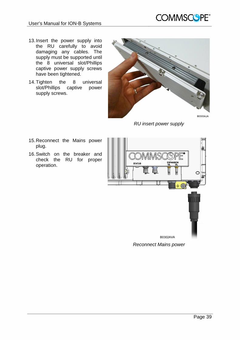
13. Insert the power supply into the RU carefully to avoid damaging any cables. The supply must be supported until the 8 universal slot/Phillips captive power supply screws have been tightened.
14. Tighten the 8 universal slot/Phillips captive power supply screws.
RU insert power supply
15. Reconnect the Mains power plug.
16. Switch on the breaker and check the RU for proper operation.
Reconnect Mains power

User’s Manual for ION-B Systems
Page 40 Manual TFAH-ES70_80_50.doc
4. TECHNICAL SUPPORT
4.1. CONTACT ADDRESSES The ION-B is developed by:
Commscope Italy Srl Via Pier De Crescenzi 40
48018 Faenza, Italy Tel: +39.0546.697111 Fax: +39.0546.682768
For further information about the product, please write to: [email protected]

User’s Manual for ION-B Systems
Page 41
4.2. RETURNING EQUIPMENT Before returning any equipment to the manufacturer for repairation or replacement, the customer should give prior notice to the manufacturer and ask for the ‘Return Material Authorisation’ (RMA request). RMA REQUEST FORM
Company name Address Contact person Invoice number Delivery note № of pieces Model 1) Serial Number 1) Lot1) Year1) Description of the failure/ defect
1) Please refer to the serial label Upon accepting your RMA request, the manufacturer will assign you a unique RMA code. You will therefore be able to return the equipment to the manufacturer. Please remember that:
· each piece of equipment must be packaged with care before shipment;
· a copy of the RMA request form must be included with the returning equipment, with clear indication of the RMA code you received from the manufacturer.
The returned pieces are able to be repaired (where possible) or replaced (when no repairations can be carried out). These operations are performed under warranty (please see the warranty conditions specified in the sales contract) or out-of-warranty. In the latter case, we will send you a bill for equipment repairation or replacement. When returning the repaired or replaced equipment, the manufacturer will issue a check report, which will be included in the packaging together with the returned pieces. The customer will be informed of any corrective actions suggested for quality assurance.
![Apha slides tfah sanyal slides[1]](https://static.fdocuments.us/doc/165x107/557c653ad8b42a855d8b46d1/apha-slides-tfah-sanyal-slides1.jpg)


![Apha slides tfah hep b & c wang slides[1]](https://static.fdocuments.us/doc/165x107/557c63d6d8b42a3e2c8b4c1b/apha-slides-tfah-hep-b-c-wang-slides1.jpg)