![Water level indicator [autosaved]](https://static.fdocuments.us/doc/165x107/587996bd1a28ab95318b6a91/water-level-indicator-autosaved.jpg)
manual for LDZX-KB, KBS (220V) · 10. low water level indicator light 11.water-shortage indicator...
20
1 JD Operation Manual LDZX Vertical Pressure Steam Sterilizer ﹙Simple Pressure Vessel﹚ (Please read the manual carefully before operating this machine) LDZX-30KBS □ LDZX-40KBS □ LDZX-50KBS □ LDZX-75KBS □
Transcript of manual for LDZX-KB, KBS (220V) · 10. low water level indicator light 11.water-shortage indicator...

1
JD
Operation Manual LDZX Vertical Pressure Steam Sterilizer
﹙Simple Pressure Vessel﹚
(Please read the manual carefully before operating this machine)
LDZX-30KBS □
LDZX-40KBS □
LDZX-50KBS □
LDZX-75KBS □

2
Catalogue ⅠSummary………………………………………………………… (2)
ⅡTechnical Characteristics of the Sterilizer………………………(2)
Ⅲ Technical Parameters……………………………………………(3)
Ⅳ Installation Requirements………………………………………(4)
ⅤOperation of the Sterilizer…………………………………………(4)
Ⅵ Care and Maintenance of the Sterilizer………………………(14)
Ⅶ Structure Chart and Electrical Diagram………………………(16)
Ⅷ Precautions………………………………………………………(17)
3
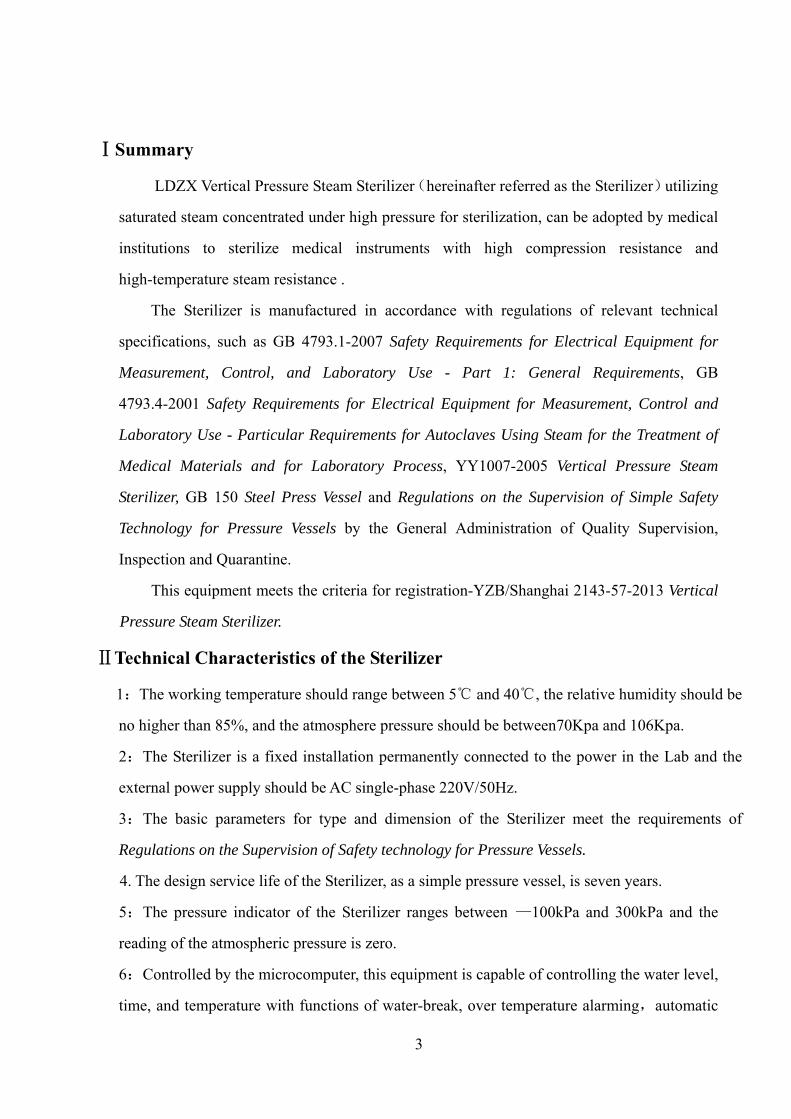
ⅠSummary
LDZX Vertical Pressure Steam Sterilizer(hereinafter referred as the Sterilizer)utilizing
saturated steam concentrated under high pressure for sterilization, can be adopted by medical
institutions to sterilize medical instruments with high compression resistance and
high-temperature steam resistance .
The Sterilizer is manufactured in accordance with regulations of relevant technical
specifications, such as GB 4793.1-2007 Safety Requirements for Electrical Equipment for
Measurement, Control, and Laboratory Use - Part 1: General Requirements, GB
4793.4-2001 Safety Requirements for Electrical Equipment for Measurement, Control and
Laboratory Use - Particular Requirements for Autoclaves Using Steam for the Treatment of
Medical Materials and for Laboratory Process, YY1007-2005 Vertical Pressure Steam
Sterilizer, GB 150 Steel Press Vessel and Regulations on the Supervision of Simple Safety
Technology for Pressure Vessels by the General Administration of Quality Supervision,
Inspection and Quarantine.
This equipment meets the criteria for registration-YZB/Shanghai 2143-57-2013 Vertical
Pressure Steam Sterilizer.
ⅡTechnical Characteristics of the Sterilizer
1:The working temperature should range between 5℃ and 40℃, the relative humidity should be
no higher than 85%, and the atmosphere pressure should be between70Kpa and 106Kpa.
2:The Sterilizer is a fixed installation permanently connected to the power in the Lab and the
external power supply should be AC single-phase 220V/50Hz.
3:The basic parameters for type and dimension of the Sterilizer meet the requirements of
Regulations on the Supervision of Safety technology for Pressure Vessels.
4. The design service life of the Sterilizer, as a simple pressure vessel, is seven years.
5:The pressure indicator of the Sterilizer ranges between —100kPa and 300kPa and the
reading of the atmospheric pressure is zero.
6:Controlled by the microcomputer, this equipment is capable of controlling the water level,
time, and temperature with functions of water-break, over temperature alarming,automatic
4
power failure and protection against low water level.
7:Warning tags are attached in appropriate places to alert the user. The user is supposed to
read through the accompanying documents to master the operation of the Sterilizer.
8:The working pressure of this Sterilizer is 0.142MPa and there should be no noise if
operated normally.
9:The equipment is equipped with reliable protective earthing connection with a clear
grounding tag.
10:After sterilization, the vent valve at the bottom of the equipment will make the sterilized
items (except wares and solutions) drier as residual steam can be emitted from the valve.
11:The Sterilizer utilizes pressurized saturated steam, produced from heating medical
distilled water, to sterilize medical instruments.
12:Protection Class: 1, Pollution Degree: 2, Overvoltage Category: II, Operating Conditions:
Continuous Operation
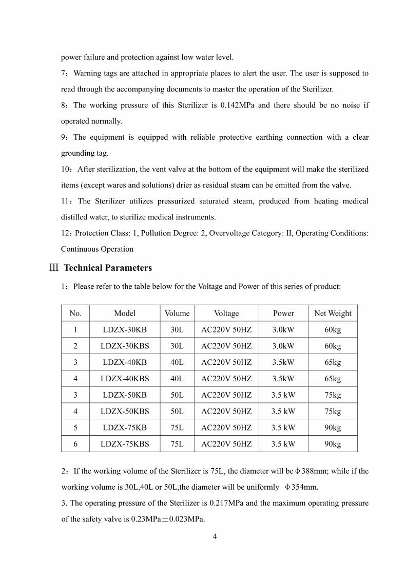
Ⅲ Technical Parameters
1:Please refer to the table below for the Voltage and Power of this series of product:
No. Model Volume Voltage Power Net Weight
1 LDZX-30KB 30L AC220V 50HZ 3.0kW 60kg
2 LDZX-30KBS 30L AC220V 50HZ 3.0kW 60kg
3 LDZX-40KB 40L AC220V 50HZ 3.5kW 65kg
4 LDZX-40KBS 40L AC220V 50HZ 3.5kW 65kg
3 LDZX-50KB 50L AC220V 50HZ 3.5 kW 75kg
4 LDZX-50KBS 50L AC220V 50HZ 3.5 kW 75kg
5 LDZX-75KB 75L AC220V 50HZ 3.5 kW 90kg
6 LDZX-75KBS 75L AC220V 50HZ 3.5 kW 90kg
2:If the working volume of the Sterilizer is 75L, the diameter will beφ388mm; while if the
working volume is 30L,40L or 50L,the diameter will be uniformly φ354mm.
3. The operating pressure of the Sterilizer is 0.217MPa and the maximum operating pressure
of the safety valve is 0.23MPa±0.023MPa.

5
4:The RT14~RT18 fuse (10×38mm,380V 32A )on the Sterilizer can effectively cut off the
overrun short-circuit current.
Ⅳ Installation Requirements
1:Before using the equipment, the operator should refer to the accompanying documents for the
operation and familiarize himself on the safety items on the documents.
2:The protective grounding wire of the Sterilizer should be
reliably connected to the outside grounding.
3:The power required for the Sterilizer is AC 220V 50HZ 25A.
4:The Sterilizer is permanently connected to the network power.
The breaker (see picture C), as a disconnecting device for the Sterilizer,
should be installed on the inner wall of the building where operation is
conveniently performed, with a transverse distance of at least 1 meter
away from the sterilizer itself and at a height of 1.2 meters above the ground. Before connected to
the breaker, the power wires should be firmly fixed to the building in case they fall off. For the
three wires connected to the network power, the wire diameters are uniformly 2.5 mm, and of them
the brown one L is live wire, the blue one N is zero line and the yellow-green one G is protective
grounding wire. The model of over-current protection device for the breaker is NDMIL50/2N30.
5: Caster wheels are equipped at the bottom of the sterilizer to facilitate handling. When the
equipment is moved to a specific location, it should be stopped by caster breakers or fixed
with a space block to avoid further slipping.
Ⅴ Operation of the Sterilizer
1: Product Identifications Instruction
(1):Control Panel
Picture A Picture B
Picture C

6
1. digital display window(upper)- red: for reading working conditions display
2. high-temperature indicator light
3. heating status light
4. low-temperature indicator light
5. key for “increase”
6. key for “confirmation”
7. key for “decrease”
8. low water level indicator light
9. water-shortage indicator light
10. high water level indicator light
11. power switch
12. digital display window(lower)- green: temperature and time setting
13. shift key
Picture D
(2):Warning Tags Picture E
Watch out (please refer to the
accompanying documents)!
Caution! Hot Protective Conductor
Terminal Blocks
2: Instructions on the Placement of the Sterilizer
(1)The Sterilizer must be put alone in an independent spacious room with good ventilation
and smooth floor. No other equipment or caustic goods shall be put in the same room with it.
(2)The equipment must be put in the position where it can be conveniently operated and
switched off and no other objects should be placed in the 60cm- diameter circle with the
Sterilizer as the center.
(3)The fuse, heating tube, solid state relay, pressure gauge, safety valve and sealing ring on
7
the equipment are all consumables that the equipment should be placed in a position where
these parts and components can be easily disassembled and installed.
(4)Incrustation and deposits will emerge after the equipment has been repeatedly used,so that
the Sterilizer should be placed in a position with a sewer where cleaning is convenient.
3:Operation of the Equipment
The service life of the Sterilizer as a simple pressure vessel is seven years. It is
unnecessary to have the accompanying documents of the pressure vessel registered in the
local auditing agency for filing. Once it comes to the end of his service life, the Sterilizer is
supposed to be scrapped and it can not be reused unless being regularly checked by the local
Inspection and Testing Institution with Regular Inspection of Pressure Vessels as the
reference. The operator must be well trained to familiarize with the operation of the pressure
vessel. Each operation must be performed in accordance with the requirements of instruction
book to prevent any mis-operation or accidents. When the equipment is working, someone
professional must be available to avoid any accident. Once the pressure vessel has come into
use, no patching or welding repairs should happen to the shell of the sterilizer. The safety
valve should be sent to the Supervision and Inspection Institution for verification at least
once a year.
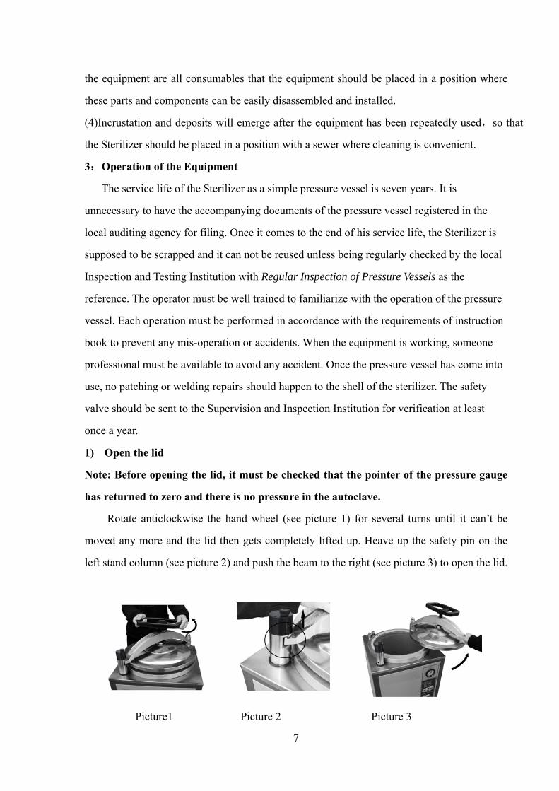
1) Open the lid
Note: Before opening the lid, it must be checked that the pointer of the pressure gauge
has returned to zero and there is no pressure in the autoclave.
Rotate anticlockwise the hand wheel (see picture 1) for several turns until it can’t be
moved any more and the lid then gets completely lifted up. Heave up the safety pin on the
left stand column (see picture 2) and push the beam to the right (see picture 3) to open the lid.
Picture1 Picture 2 Picture 3
8
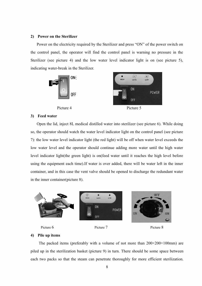
2) Power on the Sterilizer
Power on the electricity required by the Sterilizer and press “ON” of the power switch on
the control panel, the operator will find the control panel is warning no pressure in the
Sterilizer (see picture 4) and the low water level indicator light is on (see picture 5),
indicating water-break in the Sterilizer.
Picture 4 Picture 5
3) Feed water
Open the lid, inject 8L medical distilled water into sterilizer (see picture 6). While doing
so, the operator should watch the water level indicator light on the control panel (see picture
7): the low water level indicator light (the red light) will be off when water level exceeds the
low water level and the operator should continue adding more water until the high water
level indicator light(the green light) is on(feed water until it reaches the high level before
using the equipment each time).If water is over added, there will be water left in the inner
container, and in this case the vent valve should be opened to discharge the redundant water
in the inner container(picture 8).
Picture 6 Picture 7 Picture 8
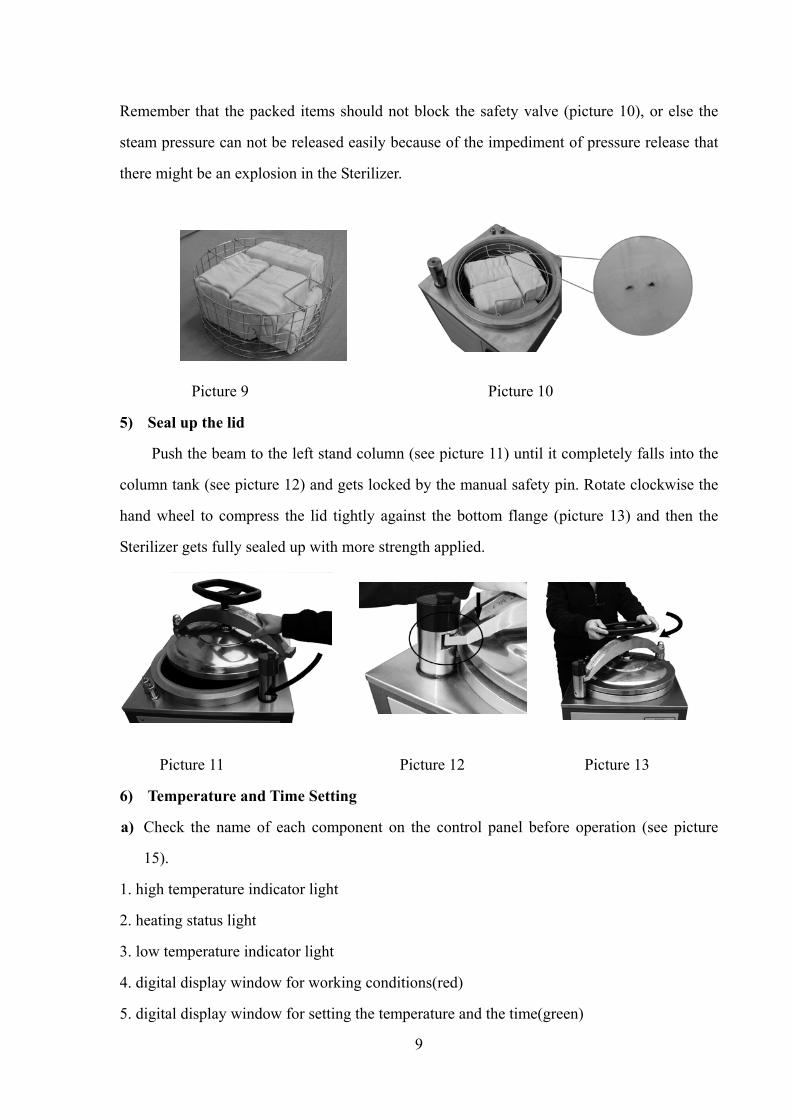
4) Pile up items
The packed items (preferably with a volume of not more than 200×200×100mm) are
piled up in the sterilization basket (picture 9) in turn. There should be some space between
each two packs so that the steam can penetrate thoroughly for more efficient sterilization.
9
Remember that the packed items should not block the safety valve (picture 10), or else the
steam pressure can not be released easily because of the impediment of pressure release that
there might be an explosion in the Sterilizer.
Picture 9 Picture 10
5) Seal up the lid
Push the beam to the left stand column (see picture 11) until it completely falls into the
column tank (see picture 12) and gets locked by the manual safety pin. Rotate clockwise the
hand wheel to compress the lid tightly against the bottom flange (picture 13) and then the
Sterilizer gets fully sealed up with more strength applied.
Picture 11 Picture 12 Picture 13
6) Temperature and Time Setting
a) Check the name of each component on the control panel before operation (see picture
15).
1. high temperature indicator light
2. heating status light
3. low temperature indicator light
4. digital display window for working conditions(red)
5. digital display window for setting the temperature and the time(green)

10
6. key for “confirmation”
7.key for “increase”
8. shift key
9.key for “decrease”
10. low water level indicator light
11.water-shortage indicator light
12. high water level indicator light
13.power switch
b) Digital readouts on the control panel when powered on(see picture 15)
The upper red digital readouts display the working temperature while the lower green
digital display window is for temperature and time setting. The temperature can be adjusted
in a range from 50 to1℃ 34℃(once the temperature is more than 2℃ higher than the set
value, the microcomputer will give out high-temperature alarm and then heating suspends),
and the safety valve will open automatically to release pressure if the temperature goes
higher than 134℃. The time can be set in a range from 0 to 99 hours (with the actual
effective time determined by the water level of the Sterilization). The time displayed on the
control panel goes in the form of the countdown and the timer will not start counting down
time until the temperature within the Sterilizer has reached the set value(the timer is
incapable of timing when the safety valve has opened automatically to release pressure).
Operating Steps for Setting Temperature
① Press the key for confirmation (picture 16) to activate the adjusting block of the
setting window (green); if the green digital readouts are (picture 17) flickering, it indicates
that setting can be started now.
Picture 16 Picture 17
② Press the key for increase (picture18) to increase the temperature or key for
decrease (picture18) to reduce the temperature. Having set the temperature, the
Picture 15
11
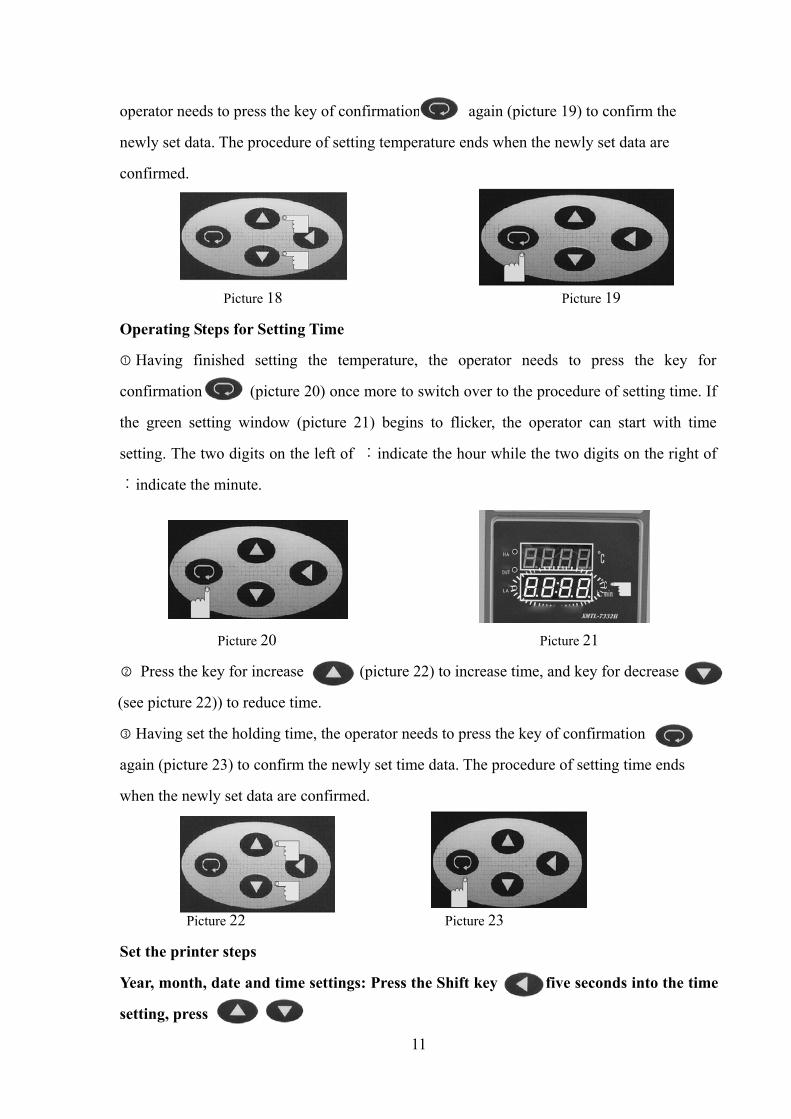
operator needs to press the key of confirmation again (picture 19) to confirm the
newly set data. The procedure of setting temperature ends when the newly set data are
confirmed.
Picture 18 Picture 19
Operating Steps for Setting Time
① Having finished setting the temperature, the operator needs to press the key for
confirmation (picture 20) once more to switch over to the procedure of setting time. If
the green setting window (picture 21) begins to flicker, the operator can start with time
setting. The two digits on the left of ︰indicate the hour while the two digits on the right of
︰indicate the minute.
Picture 20 Picture 21
② Press the key for increase (picture 22) to increase time, and key for decrease
(see picture 22)) to reduce time.
③ Having set the holding time, the operator needs to press the key of confirmation
again (picture 23) to confirm the newly set time data. The procedure of setting time ends
when the newly set data are confirmed.
Picture 22 Picture 23
Set the printer steps
Year, month, date and time settings: Press the Shift key five seconds into the time
setting, press

12
Key to set the Year Year, TH current month, day a few numbers, T-24-hour clock
Enter key to confirm.
Warning
If setting fails or there is wrong operation, the data should be reset. The operator only
needs to press the key for confirmation (picture 24) to choose temperature or time.
When the green setting window is flickering, resetting can be started.
The shift key (function key) (see picture 25) which is used to shift data when the
digital readouts are flickering, make possible the fast data adjustment.
Picture 24 Picture 25
7) Sterilization
① When the temperature and time has been set, the heating light on the control panel will
be on (green light)(see picture 26), the Sterilizer is proceeding with heating(with temperature
and pressure increasing at the same time ). With the temperature of the Sterilizer reaches the
set value, the heating light (green light) will be off, and the machine will undergo countdown
to sterilization with the residual time displayed in the setting window (Picture 27)on the
control panel.
Picture 26 Picture 27
② For different items to be sterilized, the value of time, temperature and pressure can be
determined with a reference to the following Reference Table. However these values are
subject to relevant technical standards for sterilization.

13
Reference Table for Items to Be Sterilized table 1
Items Holding
Time( minute )
Relative Steam
Temperature( )℃
Relative Steam
Pressure(MPa)
rubber 15 ~121 0.1~0.105
dressing 30-45 121~126 0.105~0.142
ware 15 121~126 0.105~0.142
instrument 10 121~126 0.105~0.142
solution 20-40 121~126 0.105~0.142
③ For items demanding strict temperature uniformity, the master vent and drain valve must
be rotated left appropriately(picture 28) in the process of sterilization to let out a little steam
and in this way the temperature throughout the Sterilizer can be unified.
Note: when rotating to the left, the steam can be
emitted, while rotating to the right, water can be
drained off.
④ If choosing manual control, when the operator makes the temperature value on the
control panel 137 , ℃ the safety valve will open automatically to release pressure
(temperature) and the time needed for sterilization has to be controlled manually. The
maximum working pressure of the safety valve is 0.23 Mpa+0.023MPa (indicated by the
arrow in Picture 29). The safety valve should be examined regularly before use, for its
flexibility and reliability (Picture 30) and it must be verified and calibrated at least once a
year. If the pressure of the Sterilizer exceeds the maximum working pressure of the safety
valve-0.23 Mpa+0.023MPa, the safety valve must be replaced with a qualified one to avoid
possible explosion caused by overpressure within the pot.
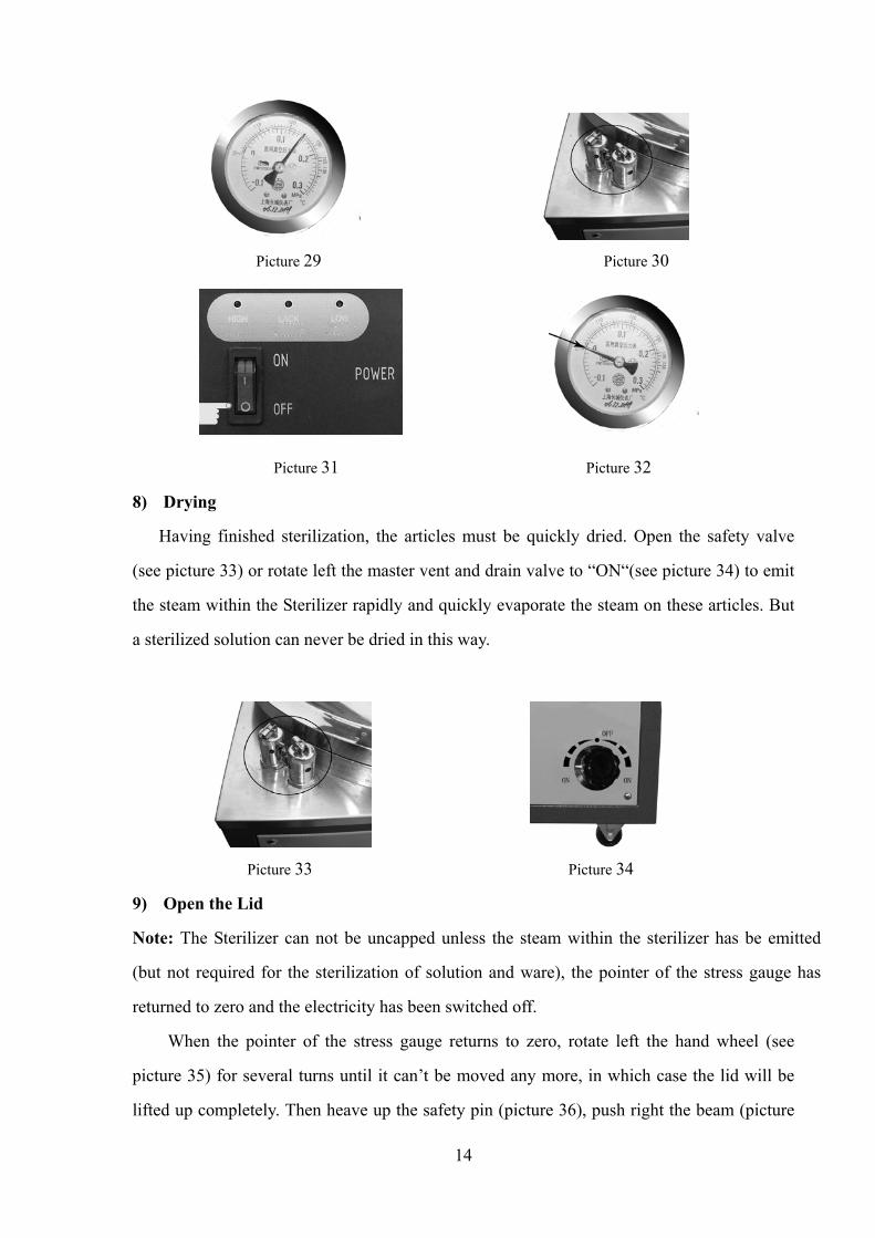
⑤ Having finished sterilization, the heating system will be automatically closed (expect
manual control). With holding time over, the control panel automatically switches to “End”.
Then the operator should press “OFF” on the power switch (see picture 31) to cut off power.
When the pointer of the pressure gauge returns to zero as demonstrated on picture 32, the
operator should open the safety valve or the master vent and drain valve to let off the residual
steam in the sterilizer.
Picture 28
14
Picture 29 Picture 30
Picture 31 Picture 32
8) Drying
Having finished sterilization, the articles must be quickly dried. Open the safety valve
(see picture 33) or rotate left the master vent and drain valve to “ON“(see picture 34) to emit
the steam within the Sterilizer rapidly and quickly evaporate the steam on these articles. But
a sterilized solution can never be dried in this way.
Picture 33 Picture 34
9) Open the Lid
Note: The Sterilizer can not be uncapped unless the steam within the sterilizer has be emitted
(but not required for the sterilization of solution and ware), the pointer of the stress gauge has
returned to zero and the electricity has been switched off.
When the pointer of the stress gauge returns to zero, rotate left the hand wheel (see
picture 35) for several turns until it can’t be moved any more, in which case the lid will be
lifted up completely. Then heave up the safety pin (picture 36), push right the beam (picture

15
37) to move away the lid. A sterilization cycle thus ends here.
Picture 35 Picture 36 Picture 37
Care and Maintenance Ⅵ
If any parts or components need to be replaced, the operation must be performed by the
qualified person that has received professional trainings or the one from the manufacturer.
Prior to the replacement, the professional must first disconnect the breaker to emit the
residual steam and wait until the pointer of the pressure gauge returns to zero. The safety
valve must be sent for verification at least once a year.
Fault Analysis and Troubleshooting
o. Fault Phenomenon Cause Analysis Troubleshooting
1
The actual temperature of the
pressure gauge doesn’t agree
with the digit displayed.
There is cold air in the Sterilizer. Open the master vent and
drain valve appropriately.
2
The water level is above the high
water level but the indicator light
(green light) is off.
The inner bore of water level
regulator gets blocked.
Dredge the pipe.
3
The high water level indicator
light (green light) is on without
having the temperature displayed
increased.
a. Holding time has not been set.
b. The solid state relay is broken.
c. The tubular electric heating
element is broken.
Set holding time.
The professional replaces the
broken solid state relay.
The professional replaces the
broken tubular electric
heating element.
4 The outer shell of the Sterilizer
is electrified while it is working.
a. The tubular electric heating
element is broken.
b. No grounding wire.
The professional replaces the
broken part. The professional
fixes the grounding wire.
5
The red digital display window
shows- - - -
a. The temperature transmitter is
broken.
b. The computer control panel is
broken.
The professional replaces the
broken parts.
Table 2
16
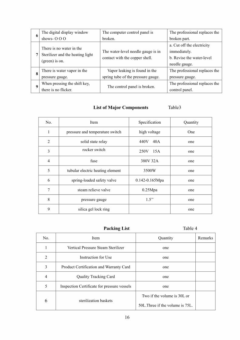
6 The digital display window
shows- O O O
The computer control panel is
broken.
The professional replaces the
broken part.
7
There is no water in the
Sterilizer and the heating light
(green) is on.
The water-level needle gauge is in
contact with the copper shell.
a. Cut off the electricity
immediately.
b. Revise the water-level
needle gauge.
8 There is water vapor in the
pressure gauge.
Vapor leaking is found in the
spring tube of the pressure gauge.
The professional replaces the
pressure gauge.
9 When pressing the shift key,
there is no flicker. The control panel is broken.
The professional replaces the
control panel.
List of Major Components Table3
Packing List Table 4
No. Item Quantity Remarks
1 Vertical Pressure Steam Sterilizer one
2 Instruction for Use one
3 Product Certification and Warranty Card one
4 Quality Tracking Card one
5 Inspection Certificate for pressure vessels one
6 sterilization baskets Two if the volume is 30L or
50L.Three if the volume is 75L.
No. Item Specification Quantity
1 pressure and temperature switch high voltage One
2 solid state relay 440V 40A one
3 rocker switch 250V 15A one
4 fuse 380V 32A one
5 tubular electric heating element 3500W one
6 spring-loaded safety valve 0.142-0.165Mpa one
7 steam relieve valve 0.25Mpa one
8 pressure gauge 1.5’’ one
9 silica gel lock ring one

17
1、Fault analysis and troubleshooting (see table 2).
2、List of major components (see table 3).
3、Packing list (see table 4).
Ⅶ Structure Chart and Electrical Diagram
1.hand wheel 2.right stand column 3.safety valve, steam release valve 4.castor wheel
5. safety pin 6.left stand column 7. vent and drain valve 8.beam
9. lid 10. autoclave body 11. pressure gauge 12. control panel
Electrical Diagram
SH power switch; ST touch controlled panel; BL water level sensor; BH temperature sensor
SWJ-8003 computer-controlled circuit board; QT1 temperature controlled switch;
HR pressure indicator light; HBR buzzer;QT2 temperature/voltage controlled switch;
QT3 micro-interlock switch; L N G electrical wire; BY transformer;
18
PrecautionsⅧ
1. When loading articles to be sterilized, the safety valve and vent valve can not be
blocked and enough space must be saved for a free flow of air or else the safety valve
and vent valve will not be able to work normally, in which case accidents may happen.
2. When sterilizing a solution, the solution should be filled in a heat-resistant glass
bottle. The volume of the solution should be no more than 3/4 of the total cubage of the
glass bottle, and the bottle neck should be stopped with cotton fabric rather than
hole-free rubber or cork.
Be cautious: When finishing sterilizing a solution, the steam can not be released
immediately. You have to wait until the pointer of the pressure gauge returns to zero
before you emit the residual steam.
3. Articles of different types or different sterilization requirements, like dressing and
solution, can never be put together for sterilization to avoid any damage.
4. If the pointer of the pressure gauge has returned to zero after sterilization, but the lid
can not be easily unveiled, the operator needs to adjust the vent valve to let outside air
get into the sterilizer, in which case the vacuum will be eliminated and the lid can be
opened then.
5. If the pointer of the pressure gauge points to wrong figures or can not return to zero
after being repeatedly used, the pressure gauge should be examined and repaired or
replaced. It should be calibrated with the standard pressure gauge regularly, and if it fails
to work, it should be replaced.
6. The Sterilizer shall be kept clean and dry for longer service term. The rubber seal is
aging as it is used day and day that it should be replaced regularly.
7. Instructions on the replacement of the fuse and other components: when plugged into a power
supply, but the power source indicator light is off, the operator should check if the fuse has been
damaged. If found broken, the fuse should be replaced immediately to rework the equipment.
8. The safety valve equipped on the Sterilizer should be sent to the local supervision
department for validation. If found out of the specification, the safety valve should be
replaced timely to avoid any accidents

19
9. The manufacturer shall replace or repair a broken component for free on condition
that the user operates strictly in accordance with rules in Instructions for Use and he or
she has altered no internal structure of the component within 12 months from the date of
purchase.
10. Protective Conductor Terminal; Caution! Hot; Caution! Danger
(please refer to the accompanying documents).
11. The electric parts of the equipment can be bought from us or replaced with identical
ones with safety certification in the market.
12. The Sterilizer coming under the category of simple pressure vessel must make the
medical distilled water as the media for sterilization. The service life for the Sterilizer is
seven years.
13. The equipment should be cleaned once a week. When cleaning it, brush off the
incrustant attached to the inner container with a hairbrush, and then scrub it clean with a
piece of clean cloth.
14. If any components listed in table 3 need replacing, the personnel responsible shall
contact the manufacturer for help instead of disassembling them himself/herself.

20
1. The nut shown in the picture should be checked regularly and the Sterilizer can not be
until the nut is screwed down, 2. As a special pressure vessel, the equipment should be separately placed in an
independent room where only the professional with qualified license can perform the operation and maintenance of the equipment.