Manual Eixos Diferenc MS113 2012-06 ING - Meritor - Home · 5 - Removal and disassembly ... M14 x...
47
Edition october/11 MAINTENANCE MANUAL Differential Axle MS - 113
Transcript of Manual Eixos Diferenc MS113 2012-06 ING - Meritor - Home · 5 - Removal and disassembly ... M14 x...

Edition october/11
MAINTENANCE MANUAL
Differential Axle
MS - 113

MAINTENANCE MANUAL
Index
1 - Notes to Technical Assistance ........................................................................... 03
2 - Exploded View MS-113 ...................................................................................... 04
3 - Exploded View MS-113 Plus .............................................................................. 05
4 - Introduction ......................................................................................................... 06
5 - Removal and disassembly .................................................................................. 07
6 - Prepare Parts for Assembly ................................................................................ 13
7 - Assembly and Installation ................................................................................... 21
8 -TorqueSpecifications ......................................................................................... 35
9 - Lubrication .......................................................................................................... 36
10 - Towing Instructions ............................................................................................. 38
11 - Special Tools ...................................................................................................... 40
12 - Failures and Causes ........................................................................................... 41


3
Notes about Technical Assistance
MAINTENANCE MANUAL
Before you Begin
CAUTIONThIs MANUAL INCLUdEs ThE MOdELs Ms-113 ANd Ms-113 PLUs.ThIs MANUAL PrOvIdEs INsTrUCTIONs fOr MErITOr’s MOdEL Ms-113 ANd Ms-113 PLUs sINgLE-rEdUCTION rEAr AxLE.1. rEAd ANd UNdErsTANd ALL INs-
TrUCTIONs ANd PrOCEdUrEs BEfO-rE yOU BEgIN TO sErvICE COMPO-NENTs.
2. rEAd ANd OBsErvE ALL WArNINg ANd CAUTION hAzArd ALErT MEssA-gEs IN ThIs PUBLICATION. ThEy PrO-vIdE INfOrMATION ThAT CAN hELP PrEvENT sErIOUs PErsONAL INjUry, dAMAgE TO COMPONENTs, Or BOTh.
3. fOLLOW yOUr COMPANy’s MAINTE-NANCE ANd sErvICE, INsTALLATION, ANd dIAgNOsTICs gUIdELINEs.
4. UsE sPECIAL TOOLs WhEN rEqUIrEd TO hELP AvOId sErIOUs PErsONAL INjUry ANd dAMAgE TO COMPO-NENTs.
hazard Alert Messages and Torquesymbols
WArNINg
A Warning alerts you to an instruction or procedure that you must follow exactly to avoid serious perso-nal injury and dama-ge to components.
CAUTION
A Caution alerts you to an instruction or procedure that you must follow exactly to avoid damage to components.
TOrqUE
This symbol alerts you to tighten faste-ners to a specified torque value.
OBsErvATION
An OBSERVATION supply informations and suggestions that will help you to provide propper tech-nical assistance to a componente.

Exploded view Ms-113
4 MAINTENANCE MANUAL
1- Locknut, M32 x 1.5 13- Inner Bearing Cap 25- Side Gear
2- Fork 14-Differential Case 26- Differential Pinion Shaft
3- Seals 15- Differential Cap Capscrew, M14 x 2.0 27- Differential Halve
4- Screws, M5 x 1,0 16- Cotter Pins 28- Differential Case Capscrew, M14 x 1.75
5- Lock Plate 17- Thrust Washer 29- Differential-to-Housing Capscrew, M12 x 1.75 x 60
6- Pinion Case 18- Thrust Washer 30- Differential-to-Housing Capscrew, M12 x 1.75 x 30
7- O-Ring 19- Adjusting Ring 31- Breather
8- Outer Bearing Cap 20- Bearing Cap 32- Axle Housing
9- Outer Bearing Cone 21- Bearing Cone 33- Fill Plug
10- Drive Pinion 22- Ring Gear 34- Drain Plug
11- Shim 23- Differential Halve — Ring Gear Side 35- Axle Shaft
12- Inner Bearing Cone 24- Thrust Washer

5
Exploded view Ms-113 Plus
MAINTENANCE MANUAL
1- Locknut, M32 x 1,5 13- Inner Bearing Cone 25- Side Gear
2- Fork 14- Differential Cage 26- Differential Pinion Shaft
3- Seals 15- Differential Cap Capscrew, M14 x 2.0 27- Differential Halve
4- Screws, M5 x 1,0 16- Cotter Pins 28- Differential Case Capscrew, M14 x 1.75
5- Lock Plate 17- Thrust Washer 29- Differential-to-Housing Caps-crew, M12 x 1.75 x 60
6- Lock Plate 18- Thrust Washer 30- Differential-to-Housing Caps-crew, M12 x 1.75 x 30
7- O-Ring 19- Adjusting Ring 31- Breather
8- Outer Bearing cap 20 -Bearing cap 32- Axle Housing
9- Outer Bearing Cone 21- Bearing Cone 33- Fill Plug
10- Drive Pinion 22- Ring Gear 34- Drain Plug
11- Shim 23- Differential Halve — Ring Gear Side 35- Axle Shaft
12- Inner Bearing Cone 24- Thrust Washer

Introduction
6 MAINTENANCE MANUAL
Meritor’s model MS-113 and MS-113 Plus sin-gle-reduction rear axle have a single-reduction differential, which is front-mounted into the axle housing. Figure 1.1. The differential has a hy-poid drive pinion and ring gear set. Bevel gears are used in the differential assembly. All bearin-gs in the differential are tapered roller bearings.When the differential operates, there is normal differential action between the wheels all the time.
1 - ADJUSTING RING2 - DIFFERENTIAL3 - RING GEAR AND DRIVE PINION4 - TAPERED ROLLER BEARING5 - TAPERED ROLLER BEARING6 - HOUSING7 - SIDE GEAR8 - COTTER PIN
Figure 1.1
WArNINgTo prevent serious eye injury, always wear safe eye protection when you perform vehicle maintenance or service.Park the vehicle on a level surface. Block the wheels to prevent the vehicle from moving. Support the vehicle with safety stands. Do not work under a vehicle supported only by jacks. Jacks can slip and fall over. Serious personal injury and damage to components can result.Use a brass or leather mallet for assembly and disassembly procedures. Do not hit steel parts with a steel hammer. Pieces of a part can break off and cause serious personal injury.
removalAxle shafts from the Axle Assembly1. Park the vehicle on a level surface. Block the
wheels to prevent the vehicle from moving.2. Raise the rear end of the vehicle so that the
rear wheels are off the ground. Support the vehicle with safety stands. Figure 2.1.
3. Place a drain pan under the rear axle.4. Remove the drain plug from the bottom of the
axle housing. Drain the lubricant from the as-sembly. Install the drain plug and tighten it to 35 lbs.ft minimum.
5. Disconnect the driveline universal joint from the pinion input Fork on the differential. Fi-gure 2.2.
Figure 2.1
1 - SAFETY STANDS

7
removal and disassembly
MAINTENANCE MANUAL
6.Remove the capscrews from the flangesofboth axle shafts. Figure 2.3.
7. Mark each axle shaft before you remove it from the axle assembly.
Figure 2.3
differential from the Axle housing1. Place a hydraulic roller jack under the diffe-
rential.Figure 2.4.
Figure 2.4
NOTE: Two capscrews in the TOP of the differential housing secure.2. Remove all of the capscrews that secure
the carrier to the axle housing, except the two capscrews in the TOP.
3. Loosen the two capscrews in the TOP of the differential, but do not remove them.
1 - FULL ROUND BEARING CAPS
2 - END FORK3 - FORK SADDLE4 - WELD FORK 5 - BEARING STRAP 6 - CAPSCREWS7 - EASY-SERVICE BEARING
CAPS8 - SPIDER9 - SLIP FORK10 - CAPSCREWS11 - END FORK 12 - WELD FORK13 - SLIP FORK
14 - SPIDER15 - CAPSCREWS16 - END FORK17 - WELD FORK18 - SLIP FORK19 - SPIDER20 - CAPSCREWS21 - END FORK 20 - LIP FORK23 - TUBING24 - SPIDER25 - WELD FORK
1 - CAPSCREW2 - AXLE SHAFT FLANGE3 - AXLE SHAFT HUB
1 - WOOD BLOCK2 - ROLLER JACK
EASY SERVICE™
SERIE WING PERMALUBE™
SERIE “RPL” PERMALUBE™
Figure 2.2

removal and disassembly
8 MAINTENANCE MANUAL
4. Loosen the differential by striking the moun-tingflangeatseveralpointswithadead-blowhammer. Remove the two capscrews in the TOP of the differential that secure to the axle housing.
5. Use a hydraulic roller jack and lever with a round end to remove the carrier from the axle housing. Take care when you use the lever so that you don’t damage the carrier or housing flange.
WArNINgTo avoid serious personal injury and damage to components, take care when using lifting devi-ces during service and maintenance procedu-res. Inspect a lifting strap to ensure that it is not damaged. Do not subject lifting straps to shocks or drop-loading.6. Use a lifting tool to place the differential into a
carrier stand. Figure 2.5.
see the section 9 to build a stand.
differential Case and ring gear
Figure 2.5
1 - DIFFERENTIAL2 - REPAIR STAND
NOTE: Before working on the differential, inspect the gear set for damage. If the gear set is not damaged, it can be reused. Measure the ba-cklash of the gear set and record the dimen-sion. figure 2.6. see the section 4.1. Remove the cotter pins from the side gear
adjusting rings. Figure 2.7.
Figure 2.6
Figure 2.71 - COTTER PIN
2. Remove the differential bearing cap caps-crews and the cap. Figure 2.8.
3. Remove the differential adjusting ring and Bearing cap from bolted-on bearing cap side. Figure 2.9.

9
removal and disassembly
MAINTENANCE MANUAL
Figure 2.8
1 - CAPSCREWS2 - DIFFERENTIAL CAP
1 - BEARING CAP2 - ADJUSTING RING
Figure 2.9
4. Remove the differential assembly and place it onto a workbench.
5. Remove the differential adjusting ring and Bearing cap from integral bearing cap side.
drive pinion cage1. Fasten a Fork bar onto the Fork to hold the
Fork when you remove the locknut. Figure 2.10. See the Section 9 to build a Fork bar.
2. Remove the Fork locknut. Figure 2.11. Remo-ve the Fork bar.
1 - FORK BAR
Figure 2.10
Figure 2.11
1 - LOCK PLATE2 - CAPSCREW3 - PINION CAGE4 - FORK LOCKNUT
3. Remove the Fork from the drive pinion.• IftheForkistightonthedrivepinion:Usea
puller to remove the Fork.4. Remove the lock plate capscrews and the
lock plate. Figure 2.12.5. Use a spanner wrench to unscrew the pinion
cage from the carrier.6. Remove the pinion cage and the drive pinion
from the differential.7. Remove the drive pinion inner Bearing cap
from the differential.

removal and disassembly
10 MAINTENANCE MANUAL
1 - CAPSCREW2 - LOCK PLATE
Figure 2.12
disassembly
WArNINgObserve all warnings and cautions provided by the press manufacturer to avoid damage to components and serious personal injury.
differential Case and ring gear Ms-1131. Remove the capscrews from the differential
case. Figure 2.13.
Figure 2.13
1 - CAPSCREWS
2. Separate the differential case halves. Figu-re 2.14. Remove the thrust washer and side gear. Figure 2.15.
3. Remove the differential pinion shaft, differen-tial pinions and thrust washers. Figure 2.16
4. Remove the side gear and thrust washer.Fi-gure 2.17. Use a brass hammer to remove the ring gear from the differential case. Figu-re 2.18.
Figure 2.14
Figure 2.15
Figure 2.16
1 - THRUST WASHER2 - SIDE GEAR
1 - DIFFERENTIAL PINION2 - THRUST WASHER3 - DIFFERENTIAL PINION SHAFT

11
removal and disassembly
MAINTENANCE MANUAL
1 - SIDE GEAR2 - THRUST WASHER
Figure 2.17
1 - RING GEAR2 - DIFFERENTIAL CASE
Figure 2.18
5. Use a bearing puller or a press to remove the bearing cones from both halves of the differen-tial case. Figure 2.19.
1 - DIFFERENTIAL CASE
Figure 2.19
differential Case and rear ring gear Ms-113 Plus
1. Remove the ring gear capscrews. Figure 2.20.
Figure 2.201 - CAPSCREW
2. Separate the case halves. Figure 2.21. Re-move the thrust washer and the pinion. Figu-re 2.22.
3. Remove the differential pinion shaft, the side gears and the thrust washers. Figure 2.23.
4. Remove the side gear and thrust washer. Fi-gure 2.24. Use a brass hammer to remove the differential case. Figure 2.25.
Figure 2.21

removal and disassembly
12 MAINTENANCE MANUAL
Figure 2.22
1 - THRUST WASHER2 - SIDE GEAR
Figure 2.23
Figure 2.24
1 - SIDE GEAR2 - THRUST WASHER3 - DIFERENTIAL PINION SHAFT
1 - SIDE GEAR2 - THRUST WASHER
1 - RING GEAR2 - DIFFERENTIAL CASE
5. Use a bearing puller or press to remove the bearing cones of the two halves of the diffe-rential case. Figure 2.26.
1 - DIFFERENTIAL CASE
drive Pinion1. Remove and discard the pinion cage O-ring.
Figure 2.27.
1 - PINION CAGE2 - O-RING3 - OUTER BEARING CAP 4 - OUTER BEARING CONE5 - DRIVE PINION6 - SHIM7 - INNER BEARING CONE
Figure 2.25
Figure 2.26
Figure 2.27
13
Prepare Parts for Assembly
MAINTENANCE MANUAL
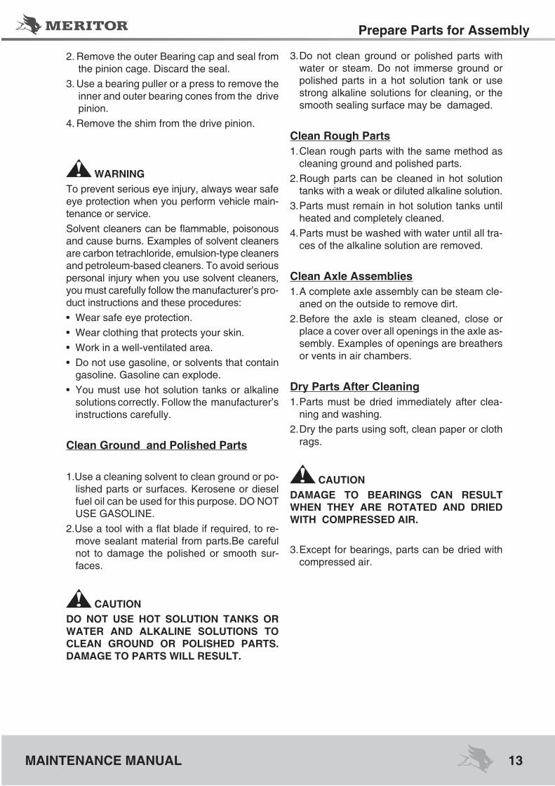
2. Remove the outer Bearing cap and seal from the pinion cage. Discard the seal.
3. Use a bearing puller or a press to remove the inner and outer bearing cones from the drive pinion.
4. Remove the shim from the drive pinion.
WArNINgTo prevent serious eye injury, always wear safe eye protection when you perform vehicle main-tenance or service.Solventcleanerscanbeflammable,poisonousand cause burns. Examples of solvent cleaners are carbon tetrachloride, emulsion-type cleaners and petroleum-based cleaners. To avoid serious personal injury when you use solvent cleaners, you must carefully follow the manufacturer’s pro-ductinstructionsandtheseprocedures:• Wearsafeeyeprotection.• Wearclothingthatprotectsyourskin.• Workinawell-ventilatedarea.• Donotusegasoline,orsolventsthatcontain
gasoline. Gasoline can explode.• Youmustusehotsolution tanksoralkaline
solutions correctly. Follow the manufacturer’s instructions carefully.
Clean ground and Polished Parts
1.Use a cleaning solvent to clean ground or po-lished parts or surfaces. Kerosene or diesel fuel oil can be used for this purpose. DO NOT USE GASOLINE.
2.Useatoolwithaflatbladeifrequired,tore-move sealant material from parts.Be careful not to damage the polished or smooth sur-faces.
CAUTIONdO NOT UsE hOT sOLUTION TANks Or WATEr ANd ALkALINE sOLUTIONs TO CLEAN grOUNd Or POLIshEd PArTs. dAMAgE TO PArTs WILL rEsULT.
3. Do not clean ground or polished parts with water or steam. Do not immerse ground or polished parts in a hot solution tank or use strong alkaline solutions for cleaning, or the smooth sealing surface may be damaged.
Clean rough Parts1. Clean rough parts with the same method as
cleaning ground and polished parts.2. Rough parts can be cleaned in hot solution
tanks with a weak or diluted alkaline solution.3. Parts must remain in hot solution tanks until
heated and completely cleaned.4. Parts must be washed with water until all tra-
ces of the alkaline solution are removed.
Clean Axle Assemblies1. A complete axle assembly can be steam cle-
aned on the outside to remove dirt.2. Before the axle is steam cleaned, close or
place a cover over all openings in the axle as-sembly. Examples of openings are breathers or vents in air chambers.
dry Parts After Cleaning1. Parts must be dried immediately after clea-
ning and washing.2. Dry the parts using soft, clean paper or cloth
rags.
CAUTIONdAMAgE TO BEArINgs CAN rEsULT WhEN ThEy ArE rOTATEd ANd drIEd WITh COMPrEssEd AIr.
3. Except for bearings, parts can be dried with compressed air.

Prepare Parts for Assembly
14 MAINTENANCE MANUAL
Prevent Corrosion on Cleaned Parts1. Apply axle lubricant to cleaned and dried
parts that are not damaged and are tobe as-sembled.
2. To store parts, apply a special material that prevents corrosion to all surfaces. Wrap cle-aned parts in a special paper that will protect the parts from moisture and prevent corro-sion.
Inspect PartsIt is very important to inspect all parts carefully and completely before the axle or differential be assembled. Check all parts for wear and repla-ce damaged parts.1. Inspect the cup, cone, rollers and cage of all
tapered roller bearings in the assembly. If any of the following conditions exist, replace the bearing.
• The center of the large-diameter end of therollers is worn level with or below the outer surface. Figure 3.1.
• Theradiusatthelarge-diameterendoftherol-lers are worn to a sharp edge. Figure 3.1.
• There isavisible rollergroove in thecuporcone inner race surfaces. The groove can be seen at the small or large-diameter end of both parts. Figure 3.2.
• Therearedeepcracksorbreaksinthecup,cone inner race or roller surfaces. Figure 3.2.
• Therearebrightwearmarksontheoutersur-face of the roller cage. Figure 3.3.
• Thereisdamageontherollersandonthesur-faces of the cup and cone inner race that tou-ch the rollers. Figure 3.4.
• There isdamageonthecupandcone innerrace surfaces that touch the rollers. Figure 3.5.
Figure 3.1
1 - WORN RADIUS2 - WORN SURFACE
1 - CRACK2 - WEAR GROVES Figure 3.2
1 - WEAR MARKSFigure 3.3
1 - MARKS AND CHEMICAL ATTACK BY CORROSION CAVITY
Figure 3.4

15
Prepare Parts for Assembly
MAINTENANCE MANUAL
• DIFFERENTIALPINIONSHAFTFigure3.7.• Teeth and splines of both differential side
gears• Teethandboreofalldifferentialpinions
Figure 3.5
1 - SPALLING AND FLAKING
CAUTIONdrIvE PINION ANd rINg gEAr ArE MAChI-NEd As A MATChEd sET. WhEN yOU rE-PLACE EIThEr A drIvE PINION Or A rINg gEAr, yOU MUsT rEPLACE BOTh PArTs As A MATChEd sET. dO NOT MIx OLd ANd NEW PArTs. dAMAgE TO COMPONENTs CAN rEsULT.
2. Inspect pinions and gears for wear or dama-ge. Replace gears that are worn or damaged.
CAUTIONA ThrUsT WAshEr, dIffErENTIAL sIdE gEAr ANd PINION gEAr ArE MAChINEd As A MATChEd sET. WhEN yOU rEPLA-CE ANy Of ThEsE PArTs, yOU MUsT INsTALL A NEW MATChEd sET. dO NOT MIx OLd ANd NEW PArTs. dAMAgEd TO COMPONENTs CAN rEsULT.
3. Inspect the following main differential assem-bly parts for wear or stress. Replace parts that are damaged. Figure 3.6 and 3.7.
• Insidesurfacesofbothcasehalves• Bothsurfacesofallthrustwashers• ThedifferentialpinionshaftFigure3.6.
1 - CASE HALVES2 - PINION AND THRUST WASHER3 - SIDE GEAR AND THRUST WASHER4 - DIFFERENTIAL PINION SHAFT
Figure 3.6
1 - CASE HALVES2 - PINION AND THRUST WASHER3 - SIDE GEAR AND THRUST WASHER4 - DIFFERENTIAL PINION SHAFT
4. Inspect axle shafts for wear and cracks at the flange, shaft and splines. Replace theaxle shafts, if required.

Prepare Parts for Assembly
16 MAINTENANCE MANUAL
repair or replace PartsNOTE: Threads must be without damage and clean so that accurate adjustments and correct torque values can be applied to fasteners and parts.
1. Replace any fastener if corners of the head are worn.
2. Replace washers if damaged.3. Replace gaskets, oil seals or grease seals at
the time of axle or differential repair.4. Clean parts and apply new silicone gasket
material where required when the axle or di-fferential is assembled. Figure 3.7.
5. Remove nicks, marks and burrs from parts withmachinedorgroundsurfaces.Useafinefile,indiastone,emeryclothorcrocuscloth.
6. Clean and repair threads of fasteners and ho-les. Use a die, a tap of the correct size, or a finefile.
1 - REMOVE SILICONE GASKET FROM PARTS
Figure 3.8
repair Welding on Axle housingsFor Complete Welding Instructions on Meritor Drive Axle HousingsSee the Maintenance Manual 8, Drive Axle Housings. To obtain this publication, see the Service Notes page on the front inside cover of this manual.
WArNINgWear safe clothing and eye protection when you use welding equipment. Welding equip-ment can burn you and cause serious personal injury. Follow the operating instructions and sa-fety procedures recommended by the welding equipment manufacturers.Axle weld locations and welding procedures must adhere to Meritor‘s standards. Welding at locations other than those authorized by Me-ritor will void the warranty and can reduce axle beam fatigue life. Serious personal injury and damage to components can result.Meritor permits drive axle housing assembly repair welding in the following locations only.• Housing-to-coverweldjoints• Snorkelwelds• Housingseamweldsbetween the suspen-
sion attaching brackets• Bracketweldingtothedriveaxlehousing
Prepare the Axle
WArNINgThehightemperaturecausedbytheopenfla-me from the cutting torch can ignite the oil in the axle housing and can cause serious perso-nal injury.
1. Remove the oil drain plug from the bottom of the axle housing and drain the lubricant from the assembly.
CAUTIONrEMOvE ThE dIffErENTIAL frOM ThE AxLE hOUsINg BEfOrE yOU WELd ONTO AN AxLE. dO NOT WELd ONTO AN AxLE WITh ThE dIffErENTIAL INsTALLEd. ELECTrICAL ArChINg ANd dAMAgE TO COMPONENTs CAN rEsULT.

17
Prepare Parts for Assembly
MAINTENANCE MANUAL
2. Remove the differential from the axle housing. See the correct Meritor differential mainte-nance manual or the vehicle manufacturer’s instructions.
CAUTIONrEMOvE ThE BrAkE AIr ChAMBErs BEfOrE yOU WELd ONTO AN AxLE. dO NOT ExPOsE A BrAkE AIr ChAMBEr TO MOrE ThAN 250°f (121°C). dAMAgE TO ThE AIr ChAMBEr CAN rEsULT.3. Remove the wheel-end components and
brake air chambers from the axle. See the correct Meritor brake maintenance manual or the vehicle manufacturer’s instructions.
4. For housing-to-cover welds, clean the outsi-de housing-to-cover weld area 2.00-3.00-in-ches (50.8-76.2 mm) past each end or side of the crack. Clean the inside area where the cover mates with the housing. Clean the area completely around the cover. Use a wire brush and a cleaning solvent that will remove dirt and grease from these areas. Figure 3.9..
1 - CLEAN THIS AREA
5. For suspension bracket welds, clean both lo-wer and upper suspension brackets and the areas of the axle housing around each bra-cket. Use a wire brush and a cleaning solvent that will remove dirt and grease from these areas.
Figure 3.9
WArNINgThe axle housing must be 70°F (21°C) or war-mer before you weld onto the axle. Do not weld onto a cold axle or weld cold parts onto an axle. Cracks in the weld area, damage to compo-nents and serious personal injury can result.
6. Ensure that the axle housing temperature measures 70°F (21°C) or warmer.
• If the axle housing temperature measureslessthan70°F(21°C):Storetheaxleinahe-ated room until the housing reaches the cor-rect temperature.
7. Heat the damaged area to approximately 300°F (149°C) before you begin welding.
8. Use suitable weld wire electrodes when you weld. Suitable weld wire electrodes include either BS EN 499 – E 42 2 B 32 H5 or BS EN 440 – G 42 2 M GSi (American Welding Society equivalents E7018 and ER70S3, respectively).
9. For complete welding instruction, see the Maintenance Manual 8. To obtain this publi-cation, see the Service Notes page on the front inside cover of this manual.
do Not Bend or straighten a damageddrive Axle housing
WArNINgReplace damaged or out-of-specification axlecomponents. Do not bend, repair or recondition axle components by welding or heat-treating. A bent axle beam reduces axle strength, affects vehicle operation and voids Meritor’s warranty. Serious personal injury and damage to compo-nents can result.
Always replace a damaged drive axle housing. Do not bend or straighten a damaged hou-sing, which can misalign or weaken it, and void Meritor’s warranty.
Prepare Parts for Assembly
18 MAINTENANCE MANUAL
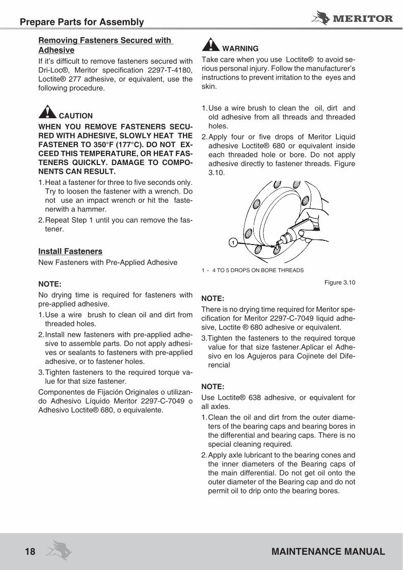
removing fasteners secured with AdhesiveIfit’sdifficulttoremovefastenerssecuredwithDri-Loc®, Meritor specification 2297-T-4180,Loctite® 277 adhesive, or equivalent, use the following procedure.
CAUTIONWhEN yOU rEMOvE fAsTENErs sECU-rEd WITh AdhEsIvE, sLOWLy hEAT ThE fAsTENEr TO 350°f (177°C). dO NOT Ex-CEEd ThIs TEMPErATUrE, Or hEAT fAs-TENErs qUICkLy. dAMAgE TO COMPO-NENTs CAN rEsULT.1.Heatafastenerforthreetofivesecondsonly.
Try to loosen the fastener with a wrench. Do not use an impact wrench or hit the faste-nerwith a hammer.
2. Repeat Step 1 until you can remove the fas-tener.
Install fastenersNew Fasteners with Pre-Applied Adhesive
NOTE:No drying time is required for fasteners with pre-applied adhesive.1. Use a wire brush to clean oil and dirt from
threaded holes.2. Install new fasteners with pre-applied adhe-
sive to assemble parts. Do not apply adhesi-ves or sealants to fasteners with pre-applied adhesive, or to fastener holes.
3. Tighten fasteners to the required torque va-lue for that size fastener.
Componentes de Fijación Originales o utilizan-do Adhesivo Líquido Meritor 2297-C-7049 o Adhesivo Loctite® 680, o equivalente.
Figure 3.10
WArNINgTake care when you use Loctite® to avoid se-rious personal injury. Follow the manufacturer’s instructions to prevent irritation to the eyes and skin.
1. Use a wire brush to clean the oil, dirt and old adhesive from all threads and threaded holes.
2.Apply four or five drops of Meritor Liquidadhesive Loctite® 680 or equivalent inside each threaded hole or bore. Do not apply adhesive directly to fastener threads. Figure 3.10.
1 - 4 TO 5 DROPS ON BORE THREADS
NOTE:There is no drying time required for Meritor spe-cificationforMeritor2297-C-7049liquidadhe-sive, Loctite ® 680 adhesive or equivalent.3.Tighten the fasteners to the required torque
value for that size fastener.Aplicar el Adhe-sivo en los Agujeros para Cojinete del Dife-rencial
NOTE: Use Loctite® 638 adhesive, or equivalent for all axles.1. Clean the oil and dirt from the outer diame-
ters of the bearing caps and bearing bores in the differential and bearing caps. There is no special cleaning required.
2. Apply axle lubricant to the bearing cones and the inner diameters of the Bearing caps of the main differential. Do not get oil onto the outer diameter of the Bearing cap and do not permit oil to drip onto the bearing bores.

19
Prepare Parts for Assembly
MAINTENANCE MANUAL
3. Apply a single continuous bead of adhesive to the bearing bores in the differential and bearing cap. Apply the adhesive around the circumference of the smooth, ground surfa-ces only. On the integral cap side, apply the adhesive near the thread end. Do not apply adhesive onto the threaded areas. Figure 3.11.
Figure 3.12
1 - ADHESIVE2 - BEARING CAP3 - DIFFERENTIAL CASE
Figure 3.11
NOTE:Loctite 638 adhesive, or equivalent will dry in approximately two hours. Perform Steps 4 and 5 within two hours from the time you apply the adhesive. If two hours have passed since ap-plication, clean the adhesive from the parts and apply new adhesive.4. Install the main differential assembly, Bea-
ring caps and bearing cap into the differen-tial. The Bearing cap of the integral bearing cap side must be assembled from the thre-ad side. See the Section 4. Remove excess adhesive after assembly.
5. Adjust the preload of the differential bearin-gs, backlash and tooth contact patterns of the gear set as required. See the Section 4.
Applying Three Bond 1216 silicone gasket Material or Equivalent
WArNINgWhen you apply some silicone gasket materials, small amounts of acid vapor are present. To pre-vent serious personal injury, ensure that the work area is well ventilated. If the silicone gasket mate-rialgetsintoyoureyes,flushthemwithwaterfor15 minutes. Have your eyes checked by a physi-cian as soon as possible.
NOTE: The following silicone gasket products or equi-valentcanbeusedforMeritorcomponents:• SiliconeGasketmaterialThreeBondnumber
TB 1216 (Grey) or equivalent.• Loctite® Ultra grey Adhesive/Sealant num-
ber18581.• Meritorgasketmaterial/partnumber2297-F-
7052. To obtain this gasket material, see the Service Notes page on the front inside cover of this manual.
1.Useatoolwithaflatblade,ifrequired,tore-move all old gasket material from surfaces. Figure 3.12.
2. Use a cleaning solvent to clean the surfaces where you will apply silicone gasket material. Remove all oil, grease, dirt and moisture wi-thout damaging the mating surfaces. Figure 3.12.
1 - REMOVE THE OLD SEAL MATERIAL DIFFERENTIAL CARRIER PRESENTATION
CAUTIONAPPLy sILICONE gAskET MATErIAL IN A CONTINUOUs 1/8- INCh (3 MM) BEAd. If yOU UsE MOrE ThAN ThIs AMOUNT, ThE gAskET MATErIAL CAN BrEAk Off ANd PLUg LUBrICATION PAssAgEs. dAMA-gE TO COMPONENTs CAN rEsULT.
3.Applya1/8-inch(3mm)diametercontinuousbead of the silicone gasket material around one surface. Also apply the gasket material around the edge of all fastener holes on that surface. Figure 3.13.

Prepare Parts for Assembly
20 MAINTENANCE MANUAL
4. Assemble the components immediately to per-mit the silicone gasket material to compress evenly between the parts. Tighten fasteners to the required torque value for that size faste-ner. See the Section 6.
5.Wait 20 minutes before filling the assemblywith the correct lubricant. See the Section 7.
Figure 3.13
1 - DIAMETER SILICONE GASKET BEAD
gEAr sETsSee the following examples for information on identifying gear sets with matched parts. always check match numbers to verify that the gear set you will install had matched parts. Figure 3.14.
ALTERNATE LOCATIONS1 - PART NUMBER, TOOTH COMBINATION NUM-
BER, GEAR SET MATCH NUMBER, PINION CONE VA-RIATION NUMBER
2 - PART NUMBER, TOOTH COMBINATION NUMBER3 - GEAR SET MATCH NUMBER, PINION CONE VARIA-
TION NUMBER 4 - PART NUMBER, TOOTH COMBINATION NUM-
BER, GEAR SET MATCH NUMBER 5 - PART NUMBER, TOOTH COMBINATION NUM-
BER GEAR SET MATCH NUMBER
Figure 3.14
Examplesring gear and drive Pinion set
36787
36786
PArT NUMBEr LOCATION
Conventional Ring Gear
Conventional Drive Pinion
On the front face or outer diameter
At the end at thre-ads
gear set tooth combination number
At the ed at threads
gear set teeth drive Pinion loca-tion
ring gear loca-tion
On the front face or outer diameter
5-37 = gear set has afive-toothdrive
pinion and a 37-tooth ring gear
gear set match numbers
NOTE: Meritor’s drive pinions and ring gears are only available as matched sets. Each gear in a set has an alpha-numeric match number.

21
Assembly and Installation
MAINTENANCE MANUAL
At the end of the gear head
Location number drive pinion loca-tion
ring gear loca-tion
On the front face or outer diameterM29
Pinion Cone variation Number
NOTE: don’t use the pinion cone variation number when you check for a matched gear set. Use this number when you adjust the pinion dep-th in the differential. see the section 4.
At the end of the pinion gear head
Pinion Cone (PC) variation number
drive Pinion loca-tion
ring gear loca-tion Ubicación de la Corona
On the outer diameter
PC+3 +2+0,01 mmPC-5 -1 -0,02 mm
WArNINgTo prevent serious eye injury, always wear safe eye protection when you perform vehicle main-tenance or service. Observe all warnings and cautions provided by the press manufacturer to avoid damage to components and serious per-sonal injury.
Assemblydrive Pinion1. Apply lubricant to the new O-ring, differen-
tial threads, O-ring bore, pinion cage threa-ds and the inner and outer bearings Figure 4.1. To obtain this lubricant, see the Service Notes page on the front inside cover of this manual.
1 - PINION CAGE2 - O-RING3 - OUTER BEARING CAP4 - OUTER BEARING CONE5 - DRIVE PINION6 - LOCTITE 6807 - SHIM8 - INTERNAL BEARING CONE
Figure 4.1
2. Install the new O-ring in the Pinion housing.3. Install the shim (6) in the drive pinion.4. Use a press to install the pinion bearing’s in-
ternal and external cone.
Assembly of the Pinion seal into the Pinion Case1. Apply axel lubricant onto the pinion and di-
fferential case nuts and in the seal housing before assembly (if the seal is not rubberized externally). Figure 4.2.
OIL
Figure 4.2

Assembly and Installation
22 MAINTENANCE MANUAL
2.Support the differential case, position the pinion seal, and using a proper tool and a press, position and assembly into its hou-sing. See Figure 4.3.
3. Check the maximum clearance of 1,0 mm between the seal and the pinion case surfa-ce.SeeFigure4.3.Important:Themaximumvariation must be 0,5 mm along the seal pe-rimeter.
1,0 max.
Figure 4.3
differential Case and rear ring gearMs-1131. Use a press to install the bearing cones onto
both halves of the differential case.
Assembly of the Bearing Cones onto Both halves of the differential Case
1. Install the bearing cones onto both halves of the differential case using a proper tool and a press. See Figure 4.4.
Figure 4.4
NOTE:• Makesurethatthebearingconesarefree
of burrs;• Make sure that during the pressing, the
housing material is not being pulled;• Makesurethattheconesarecompletely
touching their respective.
CAUTIONhEAT ThE rINg gEAr BEfOrE sEATINg IT ONTO ThE dIffErENTIAL CAsE. dO NOT PrEss A COLd rINg gEAr ONTO ThE dIffErENTIAL CAsE. A COLd rINg gEAr WILL dAMAgE ThE dIffErENTIAL CAsE BECAUsE Of ThE TIghT fIT.
2. Heat the ring gear. A maximum temperatu-re of 340°F (170°C) can be applied at the gear web. The temperature at the gear te-eth must not exceed 250°F (120°C). Wear safe clothing and gloves while working with the hot ring gear.
3. Position the differential case on a workben-ch with the bearing cone on top.
4. Place the ring gear over the differential case immediately after the gear is heated.
Apply in the bearing pe-rimeter a string of about 1 mm in diameter - or equivalent 680 076703.

23
Assembly and Installation
MAINTENANCE MANUAL
• Iftheringgeardoesnotfiteasilyonthedi-fferentialcase:Heatthegearagain.
5. Align the ring gear and differential case capscrew holes. Rotate the ring gear as ne-cessary.
6. Use a feeler gauge to inspect for gaps between the ring gear and the differential case.
• Ifthegapexceeds0.001-inch(0.025mm)atmore than three places with an arc length greater than 1.0-inch (25.4 mm): Inspectthe differential case and ring gear for wear or damage. Repair or replace parts as ne-cessary.
7. Turn the differential case over on the work-bench so that the bearing cone is on the bottom.
8. Apply lubricant to the differential pinion shaft, thrust washers, differential pinions and side gears. To obtain this lubricant, see the Service Notes page on the front inside cover of this manual.
9. Install the thrust washer and side gear into the differential case. Figure 4.5.
10. Slide the differential pinions and thrust wa-shers onto the differential pinion shaft. Fi-gure 4.6.
11. Position the differential pinion shaft in the differential case on top of the side gear. The holes in the differential pinion shaft must align with the capscrew holes in the diffe-rential case. Figure 4.7.
12. Install the side gear and thrust washer over the differential pinions. Figure 4.8.
13. Position the case half over the side gear. Figure 4.9.
1 - SIDE GEAR2 - THRUST WASHER
Figure 4.5
1 - DIFFERENTIAL PINION2 - THRUST WASHER3 - DIFFERENTIAL PINION SHAFT
Figure 4.6
1 - ALIGN HOLES Figure 4.7
1 - THRUST WASHER2 - SIDE GEAR
Figure 4.8
Figure 4.9

Assembly and Installation
24 MAINTENANCE MANUAL
14. IInstall the capscrews through both diffe-rential case halves and into the ring gear. Use a CRISSCROSS pattern to tighten thecapscrewslikespecificationbelow:ForM14 screws, apply toque at an angle of 63 +4/-0Lb.foot(85+5/-0N.m+60º+5º/-0º)
15. Inspect the differential gears rotating resis-tance. Use the following procedure.
NOTE: • Makesurethatthebearingconesarefree
of burrs;• Make sure that during the pressing, the
housing material is not being pulled;• Makesurethattheconesarecompletely
touching their respective.
CAUTIONhEAT ThE rINg gEAr BEfOrE sEATINg IT ONTO ThE dIffErENTIAL CAsE. dO NOT PrEss A COLd rINg gEAr ONTO ThE dIffErENTIAL CAsE. A COLd rINg gEAr WILL dAMAgE ThE dIffErENTIAL CAsE BECAUsE Of ThE TIghT fIT.
2. Heat the ring gear. A maximum temperature of 340°F (170°C) can be applied at the gear web. The temperature at the gear teeth must not exceed 250°F (120°C). Wear safe clo-thing and gloves while working with the hot ring gear.
3. Position the differential case on a workbench with the bearing cone on top.
4. Place the ring gear over the differential case immediately after the gear is heated.
• Iftheringgeardoesnotfiteasilyonthediffe-rentialcase:Heatthegearagain.
5. Align the ring gear and differential case capscrew holes. Rotate the ring gear as ne-cessary.
6. Use a feeler gauge to inspect for gaps betwe-en the ring gear and the differential case.
• Ifthegapexceeds0.001-inch(0.025mm)atmore than three places with an arc length greaterthan1.0-inch(25.4mm):Inspectthedifferential case and ring gear for wear or da-mage. Repair or replace parts as necessary. Check the differential case and ring gear for wear or damage. Fix or replace the parts as necessary.
7. Turn the differential case over on the work-bench so that the bearing cone is on the bottom.
Figure 4.10
Figure 4.11
Assembly of the Bearing Cones onto Both halves of the differential Case 1. Use a press to install the bearing cones onto
both halves of the differential case
Assembly of the Bearing Cones onto Both halves of the differential Case
1. Install the bearing cones onto both halves of the differential case using a proper tool and a press. See Figure 4.11.
1 - CAPSCREWS
25
Assembly and Installation
MAINTENANCE MANUAL
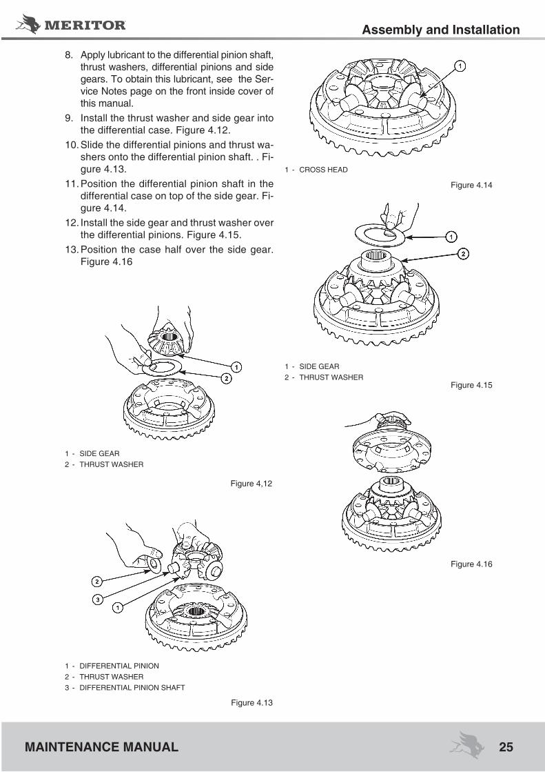
8. Apply lubricant to the differential pinion shaft, thrust washers, differential pinions and side gears. To obtain this lubricant, see the Ser-vice Notes page on the front inside cover of this manual.
9. Install the thrust washer and side gear into the differential case. Figure 4.12.
10. Slide the differential pinions and thrust wa-shers onto the differential pinion shaft. . Fi-gure 4.13.
11. Position the differential pinion shaft in the differential case on top of the side gear. Fi-gure 4.14.
12. Install the side gear and thrust washer over the differential pinions. Figure 4.15.
13. Position the case half over the side gear. Figure 4.16
Figure 4.14
Figure 4,12
Figure 4.13
1 - SIDE GEAR2 - THRUST WASHER
1 - DIFFERENTIAL PINION2 - THRUST WASHER3 - DIFFERENTIAL PINION SHAFT
1 - CROSS HEAD
Figure 4.15
1 - SIDE GEAR 2 - THRUST WASHER
Figure 4.16

Assembly and Installation
26 MAINTENANCE MANUAL
Figure 4.17
14. Install the capscrews through both diffe-rential case halves and into the ring gear. Use a CRISSCROSS pattern to tighten the capscrewsshownbelow:
1. For screws M12, apply toque angle of 37 + 7/-0Lb.(50+10/-0N.m+60º+10º/-0º)
2. For screws M14, apply toque angle of 63 + 4/-0Lb.(85+5/-0N.m+60º+5º/-0º)
15. Inspect the differential gears rotating resis-tance. Use the following procedure
1 - CAPSCREWS
differential gears rotating resistance1. Make an inspection tool using an axle shaft
that matches the spline size of the differen-tial side gear. Cut the shaft to approximately 12-inches (304.8 mm). Weld a nut onto the end of the shaft. Figure 4.18.
1 - APROXIMATELY 12” (305 MM)2 - SIDE VIEW3 - WELD NUT TO END OF SHAFT4 - END VIEW
Figure 4.18
2. Place the differential and ring gear assembly in a vise. Install soft metal covers over the vise jaws to protect the ring gear.
3. Install the tool into the differential until the spines on the tool are engaged with one side gear.
4. Place a torque wrench onto the nut onto the tool and rotate the differential gears. Read the value indicated on the torque wrench.
• Ifthetorquevalueisgreaterthan50lb-ft(68N.m):Disassemblethedifferentialcaseandinspect parts for wear or damage. Repair or replace parts as necessary. Reassemble the differential case and repeat Steps 2 through 4.
InstallationPinion Cage onto the differential
1. Place the pinion cage onto the differential. Use your hands to screw the pinion cage into the differential to verify that the cage is cor-rectly installed.
2. Install the Fork locknut onto the drive pinion shaft. Do not install the Fork at this time.
3. Use appropriate tools to screw the pinion cage into the differential while rotating the pi-nion to seat the bearings.
4. Tighten the pinion cage to adjust the drive pi-nion bearing preload. Check the preload by rotating the pinion by the Fork locknut with a torque wrench. Figure 4.19. The correct tor-que is 5-20 lb.-in (5.8-23 N.m).
5. Position the pinion cage lock plate. Figure 4.20.
• If the lockplatedoesnotmatchoneof thefour possible positions: Tighten the pinioncage while checking the preload to keep it wi-thinspecification.
6. Install the capscrews and tighten them to 10-13lb-ft(14-18N•m).RemovetheForklock-nut.

27
Assembly and Installation
MAINTENANCE MANUAL
differential Case and ring gear 1. Install the Bearing cap and adjusting ring into
the bore of the integral bearing cap side of the differential.
2. Install the differential case and ring gear as-sembly into the differential.
3. Install the Bearing cap and adjusting ring into the differential on the bolted-on bearing cap side.
4. Position the cap onto the differential. Install the capscrews and tighten them to 115-140 lb-ft (155-190 N.m).
5. Adjust the differential bearings preload and ring gear backlash. Check the tooth contact patterns.
Adjust differential Bearing PreloadUse Method 1 or Method 2 below to adjust di-fferential bearing preload.
Specifications
Figure 4.21
1 - CAPSCREWS2 - LOCK PLATE
Figure 4.19
7. Install the Fork and locknut onto the drive pi-nion shaft.
8. Fasten a Fork bar to the Fork to hold the dri-ve pinion in position when you tighten the lo-cknut. Figure 4.21. See the Section 9 to build a Fork bar.
9. Tighten the locknut to 740-920 lb-ft (1000-1245N•m).
Remove the Fork bar.
1 - SPECIAL TOOL
Figure 4.20
differential bearing pre-load
5-20 lb-pol
(5,8-23,0 N.m)
Expansion between Bearing caps
0,006-0,013 pol.
(0,15-0,33 mm)
450 lbs.pé
Method 11. Attach a dial indicator onto the differential mountingflangesothatthepointerisagainstthe ring gear’s back surface.
2. Use a T-bar wrench to loosen the bearing ad-justing ring that is opposite the ring gear. Fi-gure 4.23. The dial indicator will show a small amount of endplay.

Assembly and Installation
28 MAINTENANCE MANUAL
Figure 4.22
Figure 4.23
1 - LEVER WRENCH2 - ADJUSTING RING OPPOSITE RING GEAR
3. Use one of the following procedures to move the differential and ring gear to the LEFT and RIGHT while you read the dial indicator.
A. Insert two lever between the bearing ad-justing rings and the ends of the differential case. Figure 4.24. The lever must not touch the differential bearings.
B. Insert two lever between the differential case, or the ring gear and the carrier at locations other thanspecified inStepA.Figure4.25.The lever must not touch the differential bea-rings.
1 - LEVER MUST NOT TOUCH BEARINGS.
Figure 4.24
1 - LEVER MUST NOT TOUCH BEARINGS.
Figure 4.25
4. Tighten the bearing adjusting ring until the dial indicator reads ZERO endplay. Move the differential ring to the LEFT and RIGHT as needed. If necessary, repeat Step A or B.
5. Tighten each bearing adjusting ring one no-tch from ZERO. Proceed to Check Ring Gear Runout (Radial Movement) in this section.
Method 21. Hand-tighten both adjusting rings against the
differential bearings. 2. Use a micrometer to measure the opposite
surfaces of the bearing caps at X or Y. Figu-res 4.26 e 4.27. Record the measurement
3. Tighten each bearing adjusting ring one no-tch.
4. Measure the opposite surfaces of the bea-ring caps at X or Y again. Compare the mea-surement with the one you obtained in Step 2.
Figure 4.26

29
Assembly and Installation
MAINTENANCE MANUAL
Figure 4.27Figure 4.28
1 - MICROMETER
5. Subtract the measurement you obtained in Step 2 from the measurement in Step 4. The difference is the amount the bearing caps have expanded. See the following example.
• If the measurement is 0.006-0.013-inch(0.15-0.33 mm): Proceed to Check RingGear Runout (Radial Movement) in this sec-tion.
• Ifthemeasurementisnotwithinthespecifi-cationsabove:RepeatSteps3and4asne-cessary
sample differential Bearing Preload Calcu-lation
x or y Measu-rement Before Tightening Ad-justing rings
x or y Measu-rement After
Tightening Ad-justing rings
Amount Bearing Caps have Expan-
ded
13,927 inch.
353,74 mm
13,936 inch.
353,97 mm
0,009 inch.
0,23 mm
Check ring gear run Out (radial Mo-vement)
1. Attach a dial indicator onto the differential’s mountingflange.Figure4.28.
2. Adjust the dial indicator so that the pointer is against the ring gear’s back surface. Set the dial indicator to ZERO.
3. Rotate the differential and ring gear. Read the dial indicator. Runout must not exceed 0.008-inch (0.200 mm).
• If runout exceeds the specification above:Remove the differential and ring gear assem-bly from the differential. See the Section 2 and Steps 4-5 below.
• If runout is within specification: Proceed toRing Gear Backlash in this section.
4. Check the differential parts including the case for wear and damage. Repair or repla-ce parts as necessary.
5. Install the differential and ring gear into the case. Repeat the preload adjustment of the differential bearings.
ring gear Backlash
Specifications
Backlash setting ran-ge for old gear sets
0,008 - 0,018 inch.
(0,20 - 0,46 mm)
Backlash setting for new gear sets
0,005 - 0,015 inch.
(0,13 - 0,25 mm)
After checking the tooth contact patterns, the backlash can be adjustedwithin specificationlimits, if needed. To change the location of the pattern, use the following procedures.

Assembly and Installation
30 MAINTENANCE MANUAL
1.Attachadialindicatorontothemountingflan-ge of the differential. Figure 4.29.
2. Adjust the dial indicator so that the plunger or pointer is against the tooth surface.
Figure 4.29
3. Adjust the dial indicator to ZERO. Hold the dri-ve pinion in position.
4. After reading the dial indicator, rotate the di-fferential and ring gear a small amount in both directions against the drive pinion teeth.
• Ifthebacklashreadingiswithinspecification:Check the tooth contact patterns.
• Ifthebacklashreadingisnotwithinspecifica-tion:Adjustbacklashasnecessary.
5. Loosen one bearing adjusting ring one no-tch, then tighten the opposite ring the same amount. Figures 4.30 e 4.31.
• To increase backlash: Move the ring gearaway from the drive pinion.
• Todecreasebacklash:Movetheringgearto-ward the drive pinion.
1 - TIGHTEN ADJUSTING RING THIS SIDE.
2 - INCREASE BACKLASH.3 - LOOSEN ADJUSTING RING THIS
SIDE.
Figure 4.30
1 - TIGHTEN ADJUSTING RING THIS SIDE
2 - INCREASE BACKLASH3 - LOOSEN ADJUSTING RING THIS
SIDE
Figure 4.31
NOTE: When you adjust backlash, only move the ring gear. do not move the drive pinion.6. Repeat Steps 2-5 until the backlash is within specifications.
Check the Tooth Contact Patterns (Ba-cklash) of the gear setIn the following procedures, movement of the contact pattern in the length of the tooth is indi-cated as toward the heel or toe of the ring gear. Figure 4.32.Always check tooth contact patterns on the dri-ve side of the gear teeth. Figure 4.35.
1 - TOE2 - HEEL
Figure 4.32

31
Assembly and Installation
MAINTENANCE MANUAL
1. Adjust the backlash of a new gear set to 0.005-0.015-inch (0.13-0.38 mm). Adjust the backlash of an old gear set to the setting that you measured before the differential was di-sassembled. See the Ring Gear Backlash in this section.
2. Apply a marking compound onto approxima-tely 12 gear teeth of the ring gear. Rotate the ring gear so that the 12 gear teeth are next to the drive pinion. Figure 4.34.
Figure 4.34
3. Rotate the ring gear forward and backward so that the 12 gear teeth go past the drive pinion six times to get the contact patterns. Repeat if needed to get a clearer pattern. Fi-gure 4.34
4. Look at the contact patterns on the ring gear teeth. Compare the patterns to Figures 4.35, 4.36 and 4.37.
• Thelocationofgoodhand-rolledcontactpat-terns for new gear sets is toward the toe of the gear tooth and in the center between the top and bottom of the tooth. Figure 4.35.
• Whenthedifferentialisoperated,agoodpat-tern will extend approximately the full length of the gear tooth. The top of the pattern will be near the top of the gear tooth. Figure 4.38.
• The location of a good hand-rolled contactpattern for an old gear set must match the wear pattern in the ring gear. The new con-tact pattern will be smaller in area than the old wear pattern.
Figure 4.351 - GOOD HAND-ROLLED PATTERN
Figure 4.361 - HIGH PATTERN
Figure 4.371 - LOW PATTERN

Assembly and Installation
32 MAINTENANCE MANUAL
Figure 4.39
Figure 4.381 - GOOD PATTERN IN OPERATION
A high contact pattern indicates that the drive pinion was not installed deep enough into the differential. A low contact pattern indicates that the drive pinion was installed too deep in the dif-ferential. • If the contact patterns require adjustment:
Continue by following Step 5 to move the contact patterns between the top and bot-tom of the gear teeth.
• Ifthecontactpatternsareinthecenterofthegearteeth:ContinuebyfollowingStep6.
5. Adjust the position of the drive pinion in the differential to move the contact patterns be-tween the top and bottom of the gear teeth. Use the following procedure.
A. Disassemble the Fork, pinion cage and the drive pinion. See the Section 2.
B. Remove the inner bearing cone from the drive pinion. See the Section 2.
C. Change the bearing shim. • To correct a high contact pattern, Figure
4.36:Replace thebearingshimwitha thi-cker shim.
• To correct a low contact pattern, Figure4.37:Replacethebearingshimwithathin-ner shim.
D. Install the inner bearing cone onto the drive pinion. Install the drive pinion into the dif-ferential. See the appropriate procedures in this section.
E. Repeat Steps 2-5 until the contact patterns are in the center between the top and bot-tom of the gear teeth. Figure 4.35
6. Adjust the backlash of the ring gear within thespecificationrangetomovethecontactpatterns to the correct location in the length of the gear teeth. See the Ring Gear Ba-cklash in this section.
A. Decrease backlash to move the contact patterns toward the toe of the ring gear tee-th. Figure 4.39.
B. Increase backlash to move the contact pat-terns toward the heel of the ring gear teeth. Figure 4.40.
C. Repeat Steps 2-4 and 6 until the contact patterns are at the correct location in the length of the gear teeth.
1 - MOVE PATTERN TOWARD TOE, LOOSEN ADJUSTING RING THIS SIDE
2 - DECREASE BACKLASH3 - TIGHTEN ADJUSTING RING
1 - MOVE PATTERN TOWARD TOE, LOOSEN ADJUSTING RING THIS SIDE
2 - DECREASE BACKLASH3 - LOOSEN ADJUSTING RING
Figure 4.40

33
Assembly and Installation
MAINTENANCE MANUAL
7. Install the cotter pins into the adjusting rings so that the large end is between the adjusting ring lugs. Bend the tabs out flat against theoutboard side of the leg caps in two places. Figure 4.41.
1 - COTTER PINS
Figure 4.41
differential into the Axle housing
WArNINgSolvent cleaners can be flammable, poiso-nous and cause burns. Examples of solvent cleaners are carbon tetrachloride, emulsion--type cleaners and petroleum-based cleaners. To avoid serious personal injury when you use solvent cleaners, you must carefully follow the manufacturer’s product instructions and these procedures:• Wearsafeeyeprotection.• Wearclothingthatprotectsyourskin.• Workinawell-ventilatedarea.• Donotusegasoline,orsolventsthatcontain
gasoline. Gasoline can explode. • Youmustusehotsolution tanksoralkaline
solutions correctly. Follow the manufacturer’s instructions carefully. When you apply some silicone gasket materials, small amounts of acid vapor are present. To prevent serious personal injury, ensure that the work area is well ventilated. If the silicone gasket material getsintoyoureyes,flushthemwithwaterfor15 minutes. Have your eyes checked by a physician as soon as possible.
1. Clean the inside of the axle housing and the differential mounting surfaces. Use a clea-ning solvent and rags to remove dirt. Blow dry the cleaned areas with air. See the Sec-tion 3.
2. Inspect the axle housing for damage. Re-pair or replace the axle housing. See the Section 3.
3.Apply liquid adhesive Meritor specification2297-T-4180, or equivalent, into the threa-ded holes in the axle housing. To obtain this threadlocker, see the Service Notes page on the front inside cover of this manual. See the Section 3.
4. Apply silicone gasket material onto the diffe-rential mounting surface of the housing. See the Section. 4
WArNINgTo avoid serious personal injury and damage to components, take care when using lifting devices during service and maintenance pro-cedures. Inspect a lifting strap to ensure that it is not damaged. Do not subject lifting straps to shocks or drop-loading.5. Install the differential into the axle hou-
sing. Use a hydraulic roller jack or a lifting tool.
6. Install capscrews in the four corner loca-tions around the differential and axle hou-sing. Hand-tighten the fasteners. Figure 4.42
Figure 4.42

Assembly and Installation
34 MAINTENANCE MANUAL
7. Carefully push the differential into position. Ti-ghten the four capscrews two or three turns each in a CRISSCROSS pattern.
8. Repeat Step 7 until the four capscrews are tightened to 83-110 lb-ft (110-150 N.m).
9. Install the remaining capscrews and tighten them to 83-110 lb-ft (110-150 N.m).
Axle shafts in the Axle Assembly1. Clean the mating surfaces of the axle shaft flangeandthewheelhub.
2.Apply a 1/8-inch (3 mm) diameter bead ofRTV sealant around the mating surface of the hub and around the edge of each fastener hole.
3. Install the axle shaft into the housing. The axleshaftflangemustfitflatagainstthewhe-el hub.
fill the Axle with Lubricant1. Park the vehicle on a level surface. 2.Removethefillplugfromtheaxlehousing.3. Fill the axle housing with the correct lubricant
until the lubricant level is to the bottom of the fillplughole.SeetheSection7.
4.Install thefillplugand tighten it to35 lb-péminimum.
5. Road test the vehicle in an unloaded condition for one to two miles (1.6-3.2 km). Do not exce-ed25mph(40km/h).
6. Recheck the lubricant level. Adjust the lubri-cant level as necessary.
Figure 4.43
1 - CAPSCREW2 - AXLE SHAFT FLANGE3 - AXLE SHAFT HUB
4. Install the capscrews and tighten them to 105-115 lb-ft (140-155 N.m).
5. Connect the driveline universal joint to the pi-nion input Fork on the differential.
6. Remove the safety stands. Lower the vehi-cle. Remove the blocks from the wheels.

35
TorqueSpecifications
MAINTENANCE MANUAL
fastener dimensions Torque lb.-foot (N.m)
1- Fork Locknut M32 x 1,5 740-920 (1000-1245)
2- Adjusting Ring Lock Plate Capscrews M6 x 1,0, Class 10.9 10-13 (14-18)
3- Differential Case Caps-crews
M12 x 1,75, Class 10.9 (MS-113) M14 x 1,75, Class 10.9 (MS-113 Plus)
37 + 7/-0 Lb.ft (50+10/-0 N.m+60º+10º /-0º63+4/-0Lb.ft(85+5/-0N.m+60º+5º/-0º
4- Differential Cap Caps-crews M14 x 2,0, Class 10.9 115-140 (155-190)
5 e 6- Differential Case Caps-crew
41 x 1467 (short)41 x 1465 (long)
83-110 (110-150)
7- Axle Shaft capscrews M12 x 1,75 105-115 (140-155)
8- Fill plug 0,75-14 35 minimum9- Drain plug 0,50-14 35 minimum
10- Breather plug 297U6937 20 lb.Inch

Lubrication
36 MAINTENANCE MANUAL
description Specification
Pinion Bearing Preload Rolling Torque 5-20 lb-inch. (5,8 – 23,0 N.m)
Differential Bearing Preload 5-20 lb-inch. (5,8 – 23,0 N.m)
Expansion between Bearing cap 0,006 – 0,013 inch. (0,15 – 0,33 mm)
Differential Gears Rotating Resistance 50 lb-inch (68 N.m)
Ring Gear Runout 0,008 inch. (0,200 mm) maximum
Backlash Setting Range for Old Gear Sets 0,008 – 0,018 inch (0,20 – 0,46 mm)
Backlash Setting Range for Old Gear Sets 0,005 – 0,015 inch (0,13 – 0,25 mm)
Lubrication Capacity
Ms seriesLiters
6,8
OilChangeIntervalsandSpecificationsforalltractiverearaxles(1)
Ocupación o Operación del Vehículo
Recreational Vehicle Trailer Commercial Vans
Beverage Truck
Rescue Truck
Urban Delivery
School bus
FirefightersTruck
Utilitarian Municipal Truck
Initial Oil Change No longer required since January 1st 1993
Oil level check Every25.000miles(40.000km)orfleetmaintenanceinterval(whichevercomesfirst)
Every 10.000 miles (16.000 km), once amonth, or fleetmaintenance interval(whichevercomesfirst)
Petroleum based oil chan-ge in the axle with or without pumpandfilter.
Every 100.000 miles (160.000 km) Or annually, whi-chevercomesfirst
Every 50.000 miles (80.000 km) or annu-ally,whichevercomesfirst
Synthetic Oil change in the axlewithoutpumporfilter(2)
Every 250.000 miles (400.000 km) Or annually, whi-chevercomesfirst
Every 100.000 miles (160.000 km) or an-nually,whichevercomesfirst
Synthetic Oil change in the axlewithpumpandfiltersys-tem (2)
Every 500.000 miles (800.000 km) Every 250.000 miles (400.000 km)
Filter Exchange in the axle withpumpsystemandfilter Every 100.000 miles (160.000 km) Every 100.000 miles (160.000 km)
(1) If a No-Spin differential (non-slip) is installed, change the oil (petroleum based or synthetic) in intervals of 40,000 miles (64,000 km) or maximum range of 50,000 miles (80,000 km).
(2) This interval only applies to semi-synthetic oils and fully approved synthetic. Approved lubricants for Tractive Rear Axle relative to the approved list of oil for axle with extended drain period. To obtain this publication, see the sheet for Comments on Technical Assistance on the inside cover of this manual.
(3) Thefirstoilchange(mineraltype)shouldbebetween2000and5000km.
37
Lubrication
MAINTENANCE MANUAL
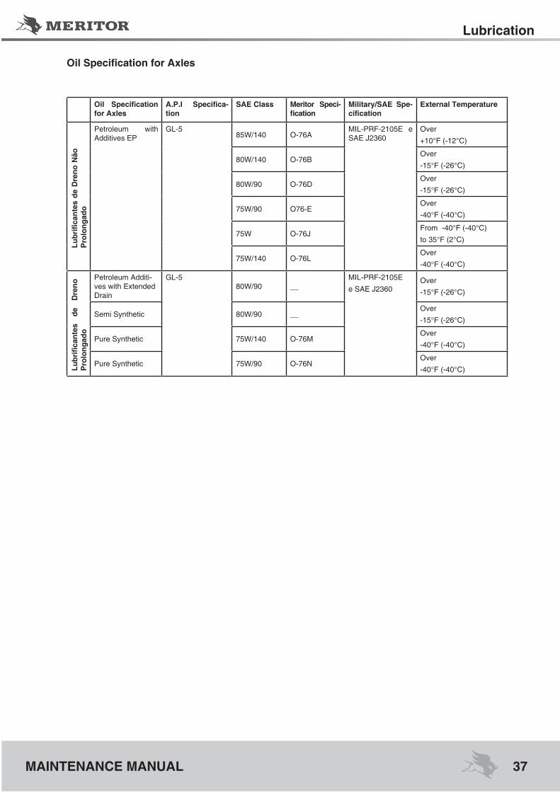
OilSpecificationforAxles
Oil Specificationfor Axles
A.P.I Specifica-tion
sAE Class Meritor speci-fication
Military/sAE spe-cification
External Temperature
Petroleum with Additives EP
GL-585W/140 O-76A
MIL-PRF-2105E e SAE J2360
Over
+10°F (-12°C)
80W/140 O-76BOver
-15°F (-26°C)
80W/90 O-76DOver
-15°F (-26°C)
75W/90 O76-EOver
-40°F (-40°C)
75W O-76JFrom -40°F (-40°C)
to 35°F (2°C)
75W/140 O-76LOver
-40°F (-40°C)
Petroleum Additi-ves with Extended Drain
GL-580W/90 __
MIL-PRF-2105E
e SAE J2360Over
-15°F (-26°C)
Semi Synthetic 80W/90 __Over
-15°F (-26°C)
Pure Synthetic 75W/140 O-76MOver
-40°F (-40°C)
Pure Synthetic 75W/90 O-76NOver
-40°F (-40°C)
LubrificantesdeDreno
Não
Pro
long
ado
LubrificantesdeDreno
P
rolo
ngad
o

Towing Instructions
38 MAINTENANCE MANUAL
WArNINgTo prevent serious eye injury, always wear safe eye protection when you perform vehicle main-tenance or service.When transporting a vehicle with the wheels of one or both drive axles on the road, it is possi-ble to damage the axles if the wrong procedu-re is used before transporting begins. Meritor recommends that you use the following pro-cedure.
Before Towing or drive-Away
WArNINgEngage the parking brake to prevent the vehi-cle from moving before you begin maintenan-ce or service procedures that require you to be under the vehicle. Serious personal injury can result.
1. Apply the vehicle parking brakes using the switch inside the cab of the vehicle.
NOTE: remove both axle shafts from the axle(s) that will remain on the road when the vehi-cle is transported.
2.Removethecapscrewsfromtheflangeoftheaxle shafts. Figure 7.1.
Figure 7.1
1 - CAPSCREW2 - AXLE SHAFT FLANGE 3 - AXLE SHAFT HUB
3. Identify each axle shaft that is removed from the axle assembly so they can be installed in the same location after transporting or repair iscompleted.Example:Matchmarkamatingaxle shaft and hub.
4. Remove the axle shaft from the axle assem-bly. Figure 7.1.
5. Install a cover over the open end of each hub where an axle shaft was removed. This will prevent dirt from entering the bearing cavity and loss of lubricant.
NOTE:If an air supply will be used for the brake system of the transported vehicle, continue with steps 6 and 7, otherwise continue with step 8.
6. Connect an auxiliary air supply to the brake system of the vehicle that is being transpor-ted. Before moving the vehicle, charge the brake system with the correct amount of air pressure to operate the brakes. See the ins-tructions supplied by the vehicle manufactu-rer for procedures and specifications. If anauxiliary air supply is not used, continue with Step 8.
7. When the correct amount of air pressure is in the brake system, release the parking brakes of the vehicle that is being transported. Step 8 is not required.
WArNINg When you work on a spring chamber, carefully follow the service instructions of the chamber manufacturer. Sudden release of a compres-sed spring can cause serious personal injury.
8. If there are spring parking brakes on the axle(s) that will remain on the road when the vehicle is transported, and they cannot be released by air pressure, manually compress and lock each spring so that the brakes are released. See the manufacturer’s instructions.

39
Towing Instructions
MAINTENANCE MANUAL
After Towing or drive-Away
WArNINgEngage the parking brake to prevent the vehi-cle from moving before you begin maintenan-ce or service procedures that require you to be under the vehicle. Serious personal injury can result
1. If an auxiliary air supply was used, apply the vehicle parking brakes using the switch insi-de the cab of the vehicle. If an auxiliary air supply was not used, begin with Step 2.
WArNINgWhen you work on a spring chamber, carefully follow the service instructions of the chamber manufacturer. Sudden release of a compres-sed spring can cause serious personal injury.
2. Apply the vehicle spring parking brakes by manually releasing each spring that was compressed before transporting started. See the manufacturer’s instructions.
3. Disconnect the auxiliary air supply, if used, from the brake system of the vehicle that was transported. Connect the vehicle’s air supply to the brake system.
4. Remove the covers from the hubs.
NOTE: Continue with steps 5-6 to install all axle shafts.
5. Install the axle shaft into the axle housing and differential in the same location it was remo-ved from.Theflangeof theaxleshaftmustbeflatagainstthehub.Rotatetheaxleshaftor the driveline as necessary to align the spli-nesandtheholesintheflangewiththestudsin the hub. Figure 8.1.
6. Install the capscrews. Tighten the capscrews to 105-115 lb-ft (140-155 N.m).
7. Check the lubricant level in the axles and hubs where the axle shafts were removed. SeetheSection7 forspecificationsand in-tervals. For Manual 1, Preventive Mainte-nance and Lubrication. To obtain this publi-cation, see the Service Notes page on the front inside cover of this manual.
special Tools
40 MAINTENANCE MANUAL
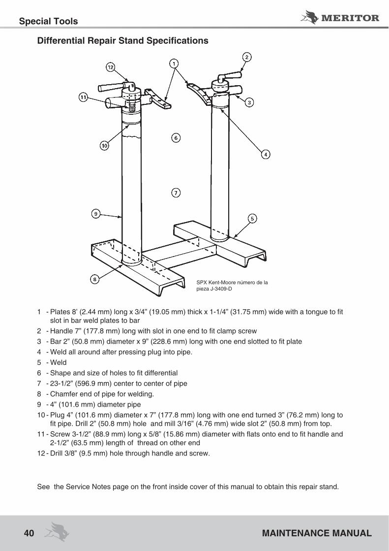
DifferentialRepairStandSpecifications
1 -Plates8’(2.44mm)longx3/4”(19.05mm)thickx1-1/4”(31.75mm)widewithatonguetofitslot in bar weld plates to bar
2 -Handle7”(177.8mm)longwithslotinoneendtofitclampscrew3 -Bar2”(50.8mm)diameterx9”(228.6mm)longwithoneendslottedtofitplate4 - Weld all around after pressing plug into pipe. 5 - Weld 6 -Shapeandsizeofholestofitdifferential7 -23-1/2”(596.9mm)centertocenterofpipe8 - Chamfer end of pipe for welding. 9 - 4” (101.6 mm) diameter pipe 10 - Plug 4” (101.6 mm) diameter x 7” (177.8 mm) long with one end turned 3” (76.2 mm) long to
fitpipe.Drill2”(50.8mm)holeandmill3/16”(4.76mm)wideslot2”(50.8mm)fromtop.11-Screw3-1/2”(88.9mm)longx5/8”(15.86mm)diameterwithflatsontoendtofithandleand
2-1/2”(63.5mm)lengthofthreadonotherend12-Drill3/8”(9.5mm)holethroughhandleandscrew.
SPX Kent-Moore número de la pieza J-3409-D
See the Service Notes page on the front inside cover of this manual to obtain this repair stand.

41
failures and Causes
MAINTENANCE MANUAL
how to make a fork Bar 1. Measure dimensions A and B of the Fork you
are servicing. Figure 8.1.
1 - FORK
Figure 8.1
2. Calculate dimensions C and D of the Fork bar by adding 0.125-0.250-inch (3.175-6.35 mm) to dimensions A and B of the Fork. Fi-gure 8.2.
WArNINgWear safe clothing and eye protection when you use welding equipment. Welding equip-ment can burn you and cause serious perso-nal injury. follow the operating instructions and safety procedures recommended by the welding equipment manufacturer.
3. To make the box section, cut and weld 1.0-inch x 2.0-inch (25.4 mm x 50.8 mm) mild steel square stock according to dimensions C and D. Figure 8.2.
4. Cut a 4.0-foot x 1.25-inch (1.21 m x 31.75 mm) piece of mild steel round stock to make the Fork bar handle. Center weld this piece to the box section. Figure 8.2.
• ToincreaseForkbarrigidity:Weldtwoanglepieces onto the handle.
1 - SPECIAL TOOLFigure 8.2
Overview of damaged Components 1. flexing overload:One look at the drive pinion shows the enti-re breakage as rough and crystalline. Broken parts showing surfaces like this clearly indicate that the damages were instantaneous and cau-sed by shock. Figure 9.1
Figure 9.1

failures and Causes
42 MAINTENANCE MANUAL
Figure 9.2
2. flexing fatigue:Flexion fatigues at the root are originated by shockand/orrepetitiveoverload,causingcra-cks found in the roots of the teeth of the gear. As the mileage increases, the initial cracks in-creases and the gear teeth will progressively weaken until the break occurs.Flexion fatigue in the root of the drive pinion te-eth is characterized by the same type of beach marksleftontheaxlesthathasflexionfatiguefailure caused by rotation. When only two or three teeth breaks, this indicates that the cause may have been an instantaneous shock load. Fatigue-induced by shock loads will also show origins that are also in line. If all the remaining teeth are broken, the likely cause was a severe shock load with continuous application of volta-ge or overload of the vehicle.Thebeachmarkscausesflexionfatiguecracksat the root, starting at the root of all affected teeth and progress to the hardened surface of the drive pinion and ring gear set teeth. Figure 9.2.
3. fatigue Initiated by shock:Shock loads are often severe enough to break the gear’s teeth at the root, parting axles in two and causing other failures as well. Often, sho-ck loads do not produce instantaneous failure, but leave the component weakened or with a crack. Depending on the severity of the shock, thedefinite failuremayoccuronlyaftermanykilometers. Figure 9.3.
Figure 9.3
4. flank CrackingFlank cracking usually causes the peeling of a metal surface very similar to what is a failure by chipping (spalling). However, a gear with cracks in thesideswilldevelopfirst longitudi-nal breaks along the surface of the gear tooth. Once these cracks appear, the failure occurs quickly. Many times, just one tooth gives a sign of decay while the other teeth are intact. But when breaks appear, soon the metal between thembeginstoflakeofftheteeth.Figure9.4.

43
failures and Causes
MAINTENANCE MANUAL
Lubrication5. Exhausted Additive damage:Meritor axles requires lubricants that meet thespecificationsEP(ExtremePressure)withadditives’baseofsulfur/phosphorus.Tofunc-tion, the required oil isGL-5, as specified L--PRF-2105E. Inappropriate grade lubricant with additives depleted or in situations of low oil level (or no oil) can take the ring gear and drive pinion to provide a lubrication failure cha-racterized by contact wear pattern, which is known as “crow’s foot”. Such patterns are des-cribed as lines or grooves in the teeth of the gear. Figure 9.5. and Figure 9.6.Meritor transmissions require that the lubri-cants are for heavy-duty engine (straight gra-de) or GL-1 petroleum with corrosion and oxi-dation inhibitor (mineral or synthetic).Lubricants for tractive axles MUST NOT be used in transmissions, as well as lubricants for transmissions MUST NOT be used in tractive axes. The mixture of the two lubricants acce-lerates deterioration and premature wear of parts in the assembly. For more information see the lubrication Maintenance Manual No. 1, Lubrication.
Figure 9.5
Figure 9.6
Figure 9.4

failures and Causes
44 MAINTENANCE MANUAL
Figure 9.7
The drive pinion teeth deteriorate until it assu-mes the form of a knife blade due to inadequa-te lubrication or the use of exhausted lubricant (old). Figure 9.7

MAINTENANCE MANUAL
Always use the Technical Manuals from...

Always use original parts
For more details, see the Spare Parts Catalog
Customer service
0800 55 55 30
Purchase the CD-ROM failure analysis of components of the axistraction
Customer ServiceAv. João Batista, 825 - Osasco - SP - 06097-105
0800 55 55 30
AfterMarket (Replace parts)Rod. Presidente Castelo Branco Km 30,5 - n° 11.250 - Barueri - SP - 06421-400
0800 55 55 30
www.meritor.com/brasil