manual digitrax decoder dn163
8
DN163K0a Fits Kato N-P42 Genesis, PA-1, E8 and Other Locomotives Features: n Digitrax LocoMotion ® System-Your locomotives look like the real thing. The Digitrax LocoMotion™ System makes them run like the real thing, too! Torque Compensation for smooth as silk silent operation. 128 Speed Step operation (14 or 28 steps can also be used). Momentum with acceleration and deceleration. Normal Direction of Travel is user selectable. Switching Speed feature for easier and faster access to yard speeds. 3 Step Speed Tables set start, mid and max voltage for custom control. 28 Step Speed Tables with 256 level resolution for precise control. n Scalable Speed Stabilization (BackEMF) with simple setup & 256 level resolution. n SuperSonic motor drive for silent operation. n FX 3 Functions for prototypical lighting effects: Constant Brightness Lighting with directional or independent control. Realistic Effects like Ditch lights, Mars lights, strobes, and many more. Dynamic and Static Qualifiers operate functions based on direction, F0 on or off, loco direction and F0, and whether loco is moving. Function Remapping of 14 functions for custom function setup. Master Light Switch turns off all lights & functions with one keystroke. Advanced Consist Function Controls n Plug ‘N Play design makes installation quick and easy. n Golden-White LEDs for added realism. n Transponder equipped ready for transponding on your layout. Compatible with digital surround sound systems. n All Mode Programming with Operations Mode Read Back-read back CV values right on the mainline. n Decoder Factory CV Reset with or without speed table initialize. n Motor Isolation Protection helps prevent damage to your loco and decoder. n Basic, Advanced & UniVersal Consisting n 2 Digit and 4 Digit Addressing n DCC Compatible n FCC Part 15, Class B RFI compliant ©2010 Digitrax, Inc. www.digitrax.com 1 Complete Train Control Run Your Trains, Not Your Track! N Scale Mobile Decoder DCC Plug ‘N Play 1.5 Amp/2.0 Amp Peak 6 FX 3 Functions, 0.5 Amp
-
Upload
modelismo-del-tren -
Category
Documents
-
view
224 -
download
2
description
manual digitrax decoder dn163
Transcript of manual digitrax decoder dn163
DN163K0aFits Kato N-P42 Genesis, PA-1, E8 and Other Locomotives
Features:n Digitrax LocoMotion® System-Your locomotives look like the real thing.
The Digitrax LocoMotion™ System makes them run like the real thing, too!
Torque Compensation for smooth as silk silent operation.
128 Speed Step operation (14 or 28 steps can also be used).
Momentum with acceleration and deceleration.
Normal Direction of Travel is user selectable.
Switching Speed feature for easier and faster access to yard speeds.
3 Step Speed Tables set start, mid and max voltage for custom control.
28 Step Speed Tables with 256 level resolution for precise control.
n Scalable Speed Stabilization (BackEMF) with simple setup & 256 levelresolution.
n SuperSonic motor drive for silent operation.
n FX3 Functions for prototypical lighting effects:
Constant Brightness Lighting with directional or independent control.
Realistic Effects like Ditch lights, Mars lights, strobes, and many more.
Dynamic and Static Qualifiers operate functions based on direction,
F0 on or off, loco direction and F0, and whether loco is moving.
Function Remapping of 14 functions for custom function setup.
Master Light Switch turns off all lights & functions with one keystroke.
Advanced Consist Function Controls
n Plug ‘N Play design makes installation quick and easy.
n Golden-White LEDs for added realism.
n Transponder equipped ready for transponding on your layout.Compatible with digital surround sound systems.
n All Mode Programming with Operations Mode Read Back-read back CVvalues right on the mainline.
n Decoder Factory CV Reset with or without speed table initialize.
n Motor Isolation Protection helps prevent damage to your loco and decoder.
n Basic, Advanced & UniVersal Consisting
n 2 Digit and 4 Digit Addressing
n DCC Compatible
n FCC Part 15, Class B RFI compliant
©2010 Digitrax, Inc. www.digitrax.com 1
Complete Train ControlRun Your Trains, Not Your Track!
N Scale
Mobile Decoder DCC Plug ‘N Play
1.5 Amp/2.0 Amp Peak6 FX3 Functions, 0.5 Amp
©2010 Digitrax, Inc. www.digitrax.com 2
Parts List1 DN163K0a Decoder 1 Instruction sheet
Installation InformationSee the Digitrax Decoder Manual for complete decoder test procedures, instal-
lation instructions, programming and technical information. Digitrax manuals
and instructions are updated periodically. Please visit www.digitrax.com for the
latest versions, technical updates and additional locomotive-specific installation
instructions.
Installation Instructions - Kato N-Scale P42 Genesis Locomotive
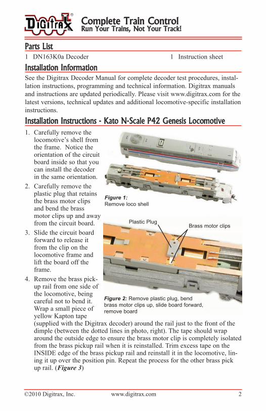
1. Carefully remove thelocomotive’s shell fromthe frame. Notice theorientation of the circuitboard inside so that youcan install the decoderin the same orientation.
2. Carefully remove theplastic plug that retainsthe brass motor clipsand bend the brassmotor clips up and awayfrom the circuit board.
3. Slide the circuit boardforward to release itfrom the clip on thelocomotive frame andlift the board off theframe.
4. Remove the brass pick-up rail from one side ofthe locomotive, beingcareful not to bend it.Wrap a small piece ofyellow Kapton tape(supplied with the Digitrax decoder) around the rail just to the front of thedimple (between the dotted lines in photo, right). The tape should wraparound the outside edge to ensure the brass motor clip is completely isolatedfrom the brass pickup rail when it is reinstalled. Trim excess tape on theINSIDe edge of the brass pickup rail and reinstall it in the locomotive, lin-ing it up over the position pin. Repeat the process for the other brass pickup rail. (Figure 3)
Complete Train ControlRun Your Trains, Not Your Track!
Figure 1:
Remove loco shell
Plastic PlugBrass motor clips
Figure 2: Remove plastic plug, bend
brass motor clips up, slide board forward,
remove board
©2010 Digitrax, Inc. www.digitrax.com 3
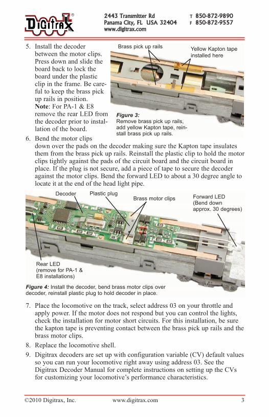
5. Install the decoderbetween the motor clips.Press down and slide theboard back to lock theboard under the plasticclip in the frame. Be care-ful to keep the brass pickup rails in position. Note: For PA-1 & e8remove the rear LeD fromthe decoder prior to instal-lation of the board.
6. Bend the motor clipsdown over the pads on the decoder making sure the Kapton tape insulatesthem from the brass pick up rails. Reinstall the plastic clip to hold the motorclips tightly against the pads of the circuit board and the circuit board inplace. If the plug is not secure, add a piece of tape to secure the decoderagainst the motor clips. Bend the forward LeD to about a 30 degree angle tolocate it at the end of the head light pipe.
7. Place the locomotive on the track, select address 03 on your throttle andapply power. If the motor does not respond but you can control the lights,check the installation for motor short circuits. For this installation, be surethe kapton tape is preventing contact between the brass pick up rails and thebrass motor clips.
8. Replace the locomotive shell.
9. Digitrax decoders are set up with configuration variable (CV) default valuesso you can run your locomotive right away using address 03. See theDigitrax Decoder Manual for complete instructions on setting up the CVsfor customizing your locomotive’s performance characteristics.
2443 Transmitter Rd T 850-872-9890Panama City, FL USA 32404 F 850-872-9557www.digitrax.com
Brass pick up rails Yellow Kapton tape
installed here
Figure 3:Remove brass pick up rails,add yellow Kapton tape, rein-stall brass pick up rails.
Figure 4: Install the decoder, bend brass motor clips overdecoder, reinstall plastic plug to hold decoder in place.
Decoder Plastic plugBrass motor clips Forward LED
(Bend down approx. 30 degrees)
Rear LED(remove for PA-1 &E8 installations)
©2010 Digitrax, Inc. www.digitrax.com 4
Customizing Your Decoder Your Digitrax decoder is ready to run and will operate using address 03 with no
additional programming. For a more prototypical railroading experience, your
decoder can be customized for your specific locomotive by programming some
of the Configuration Variables, or CVs, available. See the Digitrax Decoder
Manual or the Digitrax web site for more information.
Changing the Decoder AddressThe first CV most people change is the decoder address. This allows you to
independently control each loco with a unique address. Digitrax decoders are
shipped with CV01 (AD2), the two digit address, set to 03. Following is a brief
description of how to change the decoder address with a Digitrax DT series
throttle. See your Starter Set Manual for complete programming instructions.
1. Place the loco on the programming track. Go into Program Mode on your system.
On DT400/DT402 press PROG. On DT300, DT100 & DT200 press RUN/STOP &
FN/F0.
2. Choose AD2 for 2 digit addressing or AD4 for 4 digit addressing (DT400/DT402
and DT300). (Ad for DT100 & DT200, see set manual for 4 digit instructions).
3. Choose the address you want to set up for the decoder.
4. Complete address programming. On DT400/DT402 press ENTER. On DT300,
DT100 & DT200 press SEL.
Note: CV29 must also be programmed to enable 4 digit addressing, this is
done automatically by the DT400/DT402 & DT300 but not on earlier throttles.
Momentum-CV03 & CV04Momentum is part of the LocoMotion System. Acceleration is controlled by
CV03 and deceleration by CV04. Both come from the factory set to 000. A
range of 000 to 031 is available for both accel and decel. Try CV03:003 and
CV04:000 as a starting point for experimenting with momentum.
Speed Tables-How the Loco Responds to the ThrottleWith Digitrax LocoMotion, there are two types of speed tables: 3 Step Tables
and High Resolution 28 Step Tables. Please see your Decoder Manual for a dis-
cussion of the 28 Step Tables. The 3 Step Tables are set up by programming 3
CVs: Start Voltage (CV02), Mid point Voltage (CV06) and Max Voltage
(CV05). These values are set at 000 at the factory. All have a range of values
from 000 to 255. We recommend the following CV values as a starting point for
experimenting with speed tables.
Complete Train ControlRun Your Trains, Not Your Track!
Switching Speed, Normal Direction of Travel & Scaleable SpeedStabilization (Back EMF) FeaturesSwitching speed is controlled by CV54. The factory setting is 000 for OFF. Toturn on the switching speed feature, program CV54 to a value of 001. Whenthis feature is on, use F6 to activate and deactivate switching speed. With thefeature on the throttle’s target speed is effectively reduced by about 50% andthe effects of accel and decel programmed into the decoder are reduced by 1/4.This is useful for yard switching operations.
Normal Direction of Travel is controlled by CV29. See your decoder manualfor additional information on the settings for CV29.
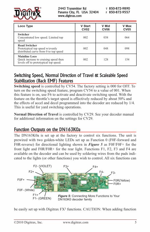
Function Outputs on the DN163K0aThe DN163K0a is set up at the factory to control six functions. The unit is
prewired with two golden-white LeDs set up as Function 0 (F0F-forward and
F0R-reverse) for directional lighting shown in Figure 5 as F0F/F0F+ for the
front light and F0R/F0R+ for the rear light. Functions F1, F2, F3 and F4 are
available on the decoder and can be used by soldering wires from the pads indi-
cated to the lights (or other functions) you wish to control. All six functions can
be easily set up with Digitrax FX3 functions. CAUTION: When adding function
2443 Transmitter Rd T 850-872-9890Panama City, FL USA 32404 F 850-872-9557www.digitrax.com
Loco Type V Start V Mid V MaxCV02 CV06 CV05
SwitcherConcentrated low speed. Limited top 002 038 064speed
Road SwitcherPrototypical top speed w/evenly 002 048 098distributed curve from 0 to top speed
Mainline LocoQuick increase to cruising speed then 002 128 154levels off to prototypical top speed.
F2- (VIOLET)
F4-
F0R(Yellow)F0R+
F1+F1- (GREEN)
F4+
F2+
F3+
F0F+
F0F- (White)
F3-
Figure 5: Connecting More Functions to Your DN163K0 decoder family
©2010 Digitrax, Inc. www.digitrax.com 5

©2010 Digitrax, Inc. www.digitrax.com 6
wires, be very careful that the wires you add do not come into contact with any
other pads or components on the board where they might create a short circuit.
The DN163K0a decoder for the Kato P42 Genesis locomotive is set up with fac-
tory-installed golden-white LeDs for forward and reverse lighting. If you
remove the rear LeD for installation in the PA-1 or e8, the headlight will be on
in the forward direction and off in reverse. The LeDs and other lights you add
can easily be set up using the decoder’s CVs to create many different Digitrax
FX3 prototypical lighting effects. The following example shows just one possi-
bility.
Function Remapping Function remapping allows you to program the function outputs of your
decoder to be controlled by selected function keys on your throttle. Please
consult the Digitrax Decoder Manual or website for information on function
remapping.
Quick Start for Digitrax FX3 Lighting Effects for the P42 GenesisThe prototype of the P42 Genesis uses ditch lights in conjunction with the
headlight. To set up
ditch lights on your P42
follow these instruc-
tions:
1. Install theDN163K0a decoderin the locomotive,test for proper oper-ation.
2. Install two incandes-cent 1.5V/15mAlamps (or LeDs) asshown in Figures 5& 6. We stronglyrecommend theincandescent lampsfor realism. Theleads from thelamps/LeDs are sol-dered to F1/F1+pads on the decoder (Figure 6) for the left ditch light and F4/F4+ pads forthe right ditch light.
3. Use a 3/16’ piece of 1/16” thick foam tape to mount the lamps on the frame.
Complete Train ControlRun Your Trains, Not Your Track!
Figure 6: Ditch Lights
Headlight1/16” thick
foam tape
Left Ditch light
wired to
decoder’s F1 &
F1+ pads
Front end
of lamps
front end
of frame
Right ditch
light wired to
decoder’s F4
& F4+ pads
3/16”
5/16”
©2010 Digitrax, Inc. www.digitrax.com 7
Leave a 5/16” clearance betweenthe front of the lamp and the frontedge of the frame for the light pipeto be re-installed. Use tweezers andbe very careful not to break thelamp when bending the lamp leads.
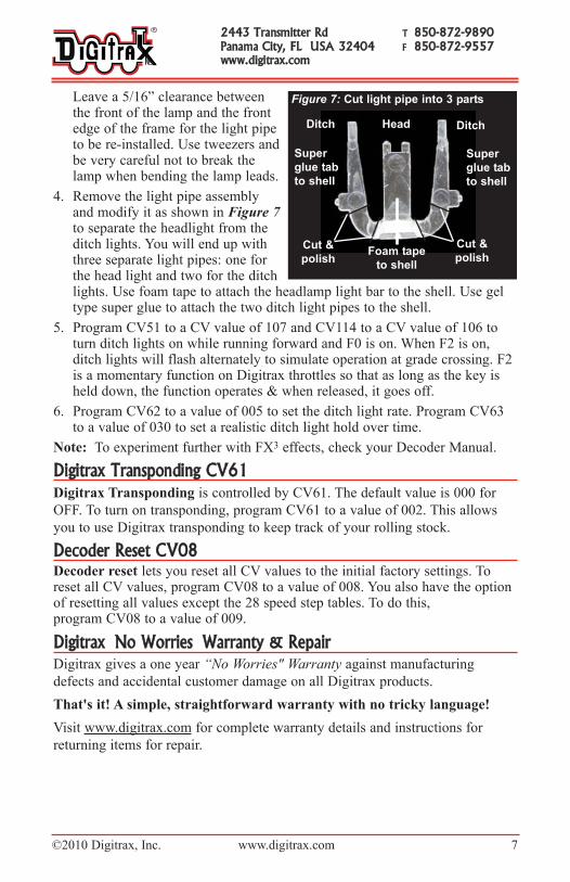
4. Remove the light pipe assemblyand modify it as shown in Figure 7
to separate the headlight from theditch lights. You will end up withthree separate light pipes: one forthe head light and two for the ditchlights. Use foam tape to attach the headlamp light bar to the shell. Use geltype super glue to attach the two ditch light pipes to the shell.
5. Program CV51 to a CV value of 107 and CV114 to a CV value of 106 toturn ditch lights on while running forward and F0 is on. When F2 is on,ditch lights will flash alternately to simulate operation at grade crossing. F2is a momentary function on Digitrax throttles so that as long as the key isheld down, the function operates & when released, it goes off.
6. Program CV62 to a value of 005 to set the ditch light rate. Program CV63to a value of 030 to set a realistic ditch light hold over time.
Note: To experiment further with FX3 effects, check your Decoder Manual.
Digitrax Transponding CV61Digitrax Transponding is controlled by CV61. The default value is 000 for
OFF. To turn on transponding, program CV61 to a value of 002. This allows
you to use Digitrax transponding to keep track of your rolling stock.
Decoder Reset CV08Decoder reset lets you reset all CV values to the initial factory settings. Toreset all CV values, program CV08 to a value of 008. You also have the optionof resetting all values except the 28 speed step tables. To do this, program CV08 to a value of 009.
Digitrax �No Worries�Warranty & RepairDigitrax gives a one year “No Worries" Warranty against manufacturing
defects and accidental customer damage on all Digitrax products.
That's it! A simple, straightforward warranty with no tricky language!
Visit www.digitrax.com for complete warranty details and instructions for
returning items for repair.
2443 Transmitter Rd T 850-872-9890Panama City, FL USA 32404 F 850-872-9557www.digitrax.com
Figure 7: Cut light pipe into 3 parts
Ditch
Super
glue tab
to shell
Foam tape
to shell
Cut &
polish
Super
glue tab
to shell
Head Ditch
Cut &
polish

Made in U.S.A.
307-3
002-0
000
2443 Transmitter RoadPanama City, FL 32404
www.digitrax.comT 850-872-9890F 850-872-9557
DN163K0aKato N-Scale P42 Genesis, PA-1, E8 & Other Locos
Available
Computer InterfaceComputer InterfaceDecoder ProgrammerDecoder ProgrammerSound ProgrammerSound Programmer
TM
EEMPIREMPIRE B BUILDERUILDERSuperSuper
00 00 00 00