MANUAL DEL DISPOSITIVO DE MEDICIÓN FIXTURE AND...
28
MANUAL DEL DISPOSITIVO DE MEDICIÓN FIXTURE AND GAGE INSTITUTO TECNOLOGICO DE PACHUCA INGENIO ITP
Transcript of MANUAL DEL DISPOSITIVO DE MEDICIÓN FIXTURE AND...

MANUAL DEL DISPOSITIVO
DE MEDICIÓN
FIXTURE AND GAGE
INSTITUTO TECNOLOGICO DE PACHUCA
INGENIO ITP

2
MANUAL DEL DISPOSITIVO
DE MEDICIÓN
FIXTURE AND GAGE
Team members:
Integrante 1. Isabel Muñoz Anaya Integrante 2. Marle García Acosta
Integrante 3. Rubén Martínez Chávez Integrante 4. Izhar Oswaldo Escudero Ornelas
Nombre del Profesor: Francisco Alfonso Chiapa Téllez
INTRODUCTION
The design and development of checking Fixture for automotive components is a tool for the
verification and dimensional analysis of mass-produced parts.
This manual, is elaborated in order to have a document that specifies clearly the operation of the
measuring device, which simulates the conditions of assembly, ensuring that the dimensions of the
parts are within the specifications of design with the reference standard ASME Y-14.5M-1994, this
arises with the need to optimize the processes of validation. During the project, are used tools like
SOLIDWORKS; enable them to meet the objective.
It seeks to work in the design and manufacture of device that complies with their respective function
in a more simple way to the one currently used, to ensure not only security and stability of the place,
but also of the operator and user.
This manual is a medium for identify with the different mechanisms, it is demonstrated by images, the
dimensions and specifications used in design of the piece, leaving in clear their components and
measures used. Your query allows to identify with clarity the functions that make up the mechanism
used; as well as also seeks to provide those elements to reach the excellence in the development of
its function.

3
MANUAL DEL DISPOSITIVO
DE MEDICIÓN
FIXTURE AND GAGE
This document is generally observed and is an instrument of information and frequent consultation for
the industrial area of the organization-, also for enrich your content and keep it updated, is suitable to
perform revisions each year, or in his case when there are been some changes.
PURPOSE
Check conditions simulating parts assembly, performing a repetitive control in lots of parts, ensuring
the same alignment and position regardless of the person performing it.
OBJECTIVE
Design and manufacture a measuring device for dimensional verification of the piece with part
number 90428152, combining knowledge of mechanical design and 3D design metrology regulations
within no more than 6 weeks.

4
MANUAL DEL DISPOSITIVO
DE MEDICIÓN
FIXTURE AND GAGE
ACTIVITIES´S SCHEDULE
NUMBER ACTIVITY RESPONSABLE DATE
1 Integration Team Ing. Alfonso Chiapa 13.09.16
2 Inscription the event Isabel Muñoz Anaya 16.09.16
3 Part delivery by GMC Ing. Alfonso Chiapa 23.09.16
4 First team meeting to establish work plan EQUIPO 01.10.16
5 Theoretical research EQUIPO 01.10.16
6 Cover page, Introduction, Objective, Purpose Marle García 03.10.16
7 PROJECT DEVELOPMENT EQUIPO 04.10.16
8 Making Process Part Oswaldo, Rubén, Isabel 04.10.16
9 Sized piece Oswaldo, Rubén, Isabel 05.10.16
10 2D and 3D part design Oswaldo, Rubén, Isabel 11.10.16
11 Search Indicators Ing. Alfonso Chiapa 11.10.16
12 Defining CRITICAL and VARIABLE EQUIPO 13.10.16
13 Proposals Prototyping EQUIPO 13.10.16
14 Definition of Materials EQUIPO 13.10.16
15 Drawing measuring device Rubén, Oswaldo 17.10.11
16 DELIVERY OF FIRST PREVIEW EQUIPO 21.10.16
17 RR analysis Jesús, Rubén, Isabel 24.10.16
18 Cost analysis Marle García 24.10.16
19 Manufacturing about Checking Fixture EQUIPO 31.10.16
20 Instructive Measurement Device EQUIPO 07.11.16
21 Device Maintenance Plan Oswaldo, Rubén, Isabel 07.11.16
22 Conclusions EQUIPO 14.11.16
23 Learned lessons EQUIPO 21.11.16
24 Bibliography EQUIPO 21.11.16
25 DELIVERY OF MANUAL EQUIPO 23.11.16
26 FINAL PRESENTATION EQUIPO 01.12.16

5
MANUAL DEL DISPOSITIVO
DE MEDICIÓN
FIXTURE AND GAGE
1. MANUFACTURING PROCESS
The manufacturing process for the fender arch part number 90428152 through a process diagram, is
described with each of the operations performed as briefly described.
Mold Injection Shakeout Assembly
Operations
1. Close mold
2. Create empty
3. Inject polymer
4. Maintain pressure within the mold
5. Remove pressure and let Quench
6. Remove and close the mold.
7. Pack

6
MANUAL DEL DISPOSITIVO
DE MEDICIÓN
FIXTURE AND GAGE
Inspections
1. Inspection
Warehouse
1. Store in finished products.
The process is performed by molding injection; it consists of different operations, inspection and
storage of finished product, described below:
1. Close mold.
In the first operation, the injection unit fills the filler material and the polymer melts.
2. Create empty.
The vacuum is created in the mold so that there is not a body or agent that can interrupt the injection
process.
3. Inject polymer.
The polymer is injected and the valve is opened, with the spindle which acts as a piston, the material
is passed through the nozzle or gate into the mold cavities.
4. Maintain pressure inside the mold.
The pressure is kept constant to ensure that the part has the right dimensions, because it tends to
shrink when is cooled.
5. Quench
The pressure is removed.
The valve is closed and the spindle rotates to upload material. The piece ends in the mold for
cooling, and this time is the most expensive because is the longest.
7
MANUAL DEL DISPOSITIVO
DE MEDICIÓN
FIXTURE AND GAGE
6. Remove
The press releases the pressure and the mold is opened; expel bars molded out of the cavity piece.
The clamping unit closes the mold and the cycle can be restarted.
7. Pack
The last operation consists of packing the piece to transport it to a warehouse of finished product.
1. Inspection
Inspection of the piece is performed to verify its quality, this inspection is done before packing the
product.
1. Warehouse
The process culminates with the store the finished product. 2. PIECE DRAWING
For the design of the part, the tolerances established in ASME Y 14.5M-1994 are taken as reference,
as follows:
2D PIECE DRAWING
2D PIECE DRAWING


10
MANUAL DEL DISPOSITIVO
DE MEDICIÓN
FIXTURE AND GAGE
DEFINITION OF CRITICAL AND VARIABLE POINTS
The analysis of critical points and variables to be measured in the piece with part number
90428152, it is taken into account that the points that must measure the device are the
following:
Distance between centers: An important point to measure is the distance that exists from
one staple to another, so you must know the distance between centers of the 7 staples.
Angle of inclination of the staples: It is observed that the inclination of the 7 staples is
different, reason why the measurement device counts on 7 pins according to each staple.
Part length: The length of the part is critical because it is not possible to assemble the part
when it does not meet the tolerances.
Part height: The height of the piece is measured with the analog indicator, which indicates
if it meets the correct height of the part.
Thickness: The thickness is measured with a micrometer, it is considered important
because it is as you can see errors in the injection molding.
Critical Points to measure
For this Control device the critical points which have been selected to be measure are
divided in two categories, the first one are by variable and the second are by attribute. The
Variables are the length between each staple and the thickness of the part. The attributes to
be measure are the total length of the part and the width. We take these points into
consideration because they are the best way to measure crucial characteristics of these parts
with the more variation. In the next drawings are been show these critical points to be
measure with their respective measurements.

11
1° The length between each staple from the part
2° The whole length of the part
3° The thickness of the part 4° The width of the part
Variable Attribute

12
3. DESIGN OF MEASURING DEVICE The design of the measuring device is made taking into account the variables and critical points to be
measured.
In the way, an analysis of repeatability and reproducibility is carried out, which is shown below the
design of the measuring device.
Analysis R&R: System to determining the error rate between the measurements, the
method and the equipment used.
Number Instrument ID Measurement Reach
Resolution Characteristics to be measure
1 Analogyc Indicator
PR-01 +/-0,006 0,01mm Heigh
2 Micrometer PR-02 +/- 0,00005 0,01mm Thickness

14
Departament Quality Control
Instructive Number IN –I-01
Instructive Name Repeatability and Reproducibility
Source Document ISO : 7.0 Realización del Producto
Fecha: 23/11/16 Versión: Original Page 1 of 3
1.0 PROCESS OWNER: Design engineering
2.0 PURPOSE:
2.0 The purpose of this document is to establish the mechanisms and steps applicable in the preparation of an R & R study
2.1 This procedure applies in analyzing the variation of a measurement system so that preventive and corrective actions are carried out in a corresponding way.
2.2 Is responsibility of the area manager to check and ensure that the equipment is calibrated.
2.3 Is responsibility of the manager area to designated the competent personal for the study
.
3.0 INSTRUCTIONS:
3.0 Select by means of the sampling system of the company the piece to be measurement
3.1 Identify the selected sample.
3.2 Use a vibration free ant temperatura controlled area
3.3 Use an indelible marker to mark critical measurement points
3.4 The selection of sample parts is critical for an appropriate analysis and depends entirely on the design of the MSA study, the purpose of the measurement system and the availability of the samples of the parts.
3.5 Define the number of observers, number of parts of the sample and the number of repeated readings
3.6 Verify that the measuring equipment is calibrated
3.7 Ensure that the measurement method is measuring the dimension of the required characteristic
3.8 The measuring instrument must have a discrimination of at least one tenth of the expected process variation for the characteristic to be measured. For example, if the characteristic variation is 0.001 "the computer must be able to read a change of 0.0001".
3.9 Select three operators that normally use the study equipment and an auxiliary for data recording.
3.10 Check that the main indicator hand shows zero before starting a measurement.
3.11 Each operator must place the measuring device at each marked point and must make at least 2, or at most, 3 repetitions.
Controlled Document, in force for use by the Quality Management System

15
Departament Quality Control
Instructive Number IN –II-01
Instructive Name Repeatability and Reproducibility
Source Document ISO : 7.0 Realización del Producto
Fecha: 23/11/16 Versión: Original Page 2 of 3
3.12 The Measurements should be made in random order to ensure that any variation or change is randomly distributed throughout the study.
3.13 The evaluator should not know which of the numbered pieces he is measuring to avoid any repetition due to the recognition of the piece.
3.14 The person performing the study should know which of the numbered parts are being measured and record the data appropriately.
3.15 The study should be controlled and observed by a person who understands the importance of conducting a reliable study.
3.16 The auxiliary operator carrying out the study collects the data and appends them to the FO-01 format.
3.17 Acceptance criteria
GRR DESICION COMMENTS
Under 10 percent Generally considered to be an acceptable measurement system.
Recommended, especially useful when trying to classify parts or when tightened process control I required.
10 percent to 30 percent May be acceptable for some applications
Decision should be bassed upon. For example, importance of application measurement, cost of measurement device, cost for rework or repair.
Over 30 percent Considered to be unacceptable
Every effort should be made to improve the measurement system.
This condition may be addressed by the use of an appropriate measurement strategy: for example, using the average result of several readings of the same part characteristic in order to reduce final measurement variation.
Controlled Document, in force for use by the Quality Management System

16
Departament Quality Control
Instructive Number IN –II-01
Instructive Name Repeatability and Reproducibility
Source Document ISO : 7.0 Realización del Producto
Fecha: 23/11/16 Versión: Original Page 3 of 3
4.0 DEFINITIONS
R&R: System to determining the percentage of error between the measurements, the method and the equipment used
4.0 REFERENCES
Norma ASME Y14.5M-1994
5.0 RECORDS
N/A
6.0 MATERIALS
Indelible marker
Maintenance form
7.0 APPENDIX
N/A
8.0 HISTORICAL REVIEW
N/A
Brief description of the changes made
9.0 APROBADO
Revision date
Brief description of the changes made
To review Revision number Made by Approved by
23/03/10 Revisión 00 Isabel Muñoz Anaya Alfonso Chiapa Téllez
Controlled Document, in force for use by the Quality Management System

17
3.63.22.82.42.01.6
25
20
15
10
5
0
Media 2.765
Desv.Est. 0.5057
N 60
MEASUREMENTS
Fre
cu
en
cia
THICKNESS HISTOGRAMNormal

18
Estudio R&R del sistema de medición - método ANOVA
R&R del sistema de medición para MEASUREMENTS
Nombre del sistema de medición : GAGE R&R
Fecha del estudio: 24.11.16
Notificado por: MARLE GARCIA
Tolerancia: 0.6 mm
Misc: TICKNESS
Tabla ANOVA de dos factores con interacción
Fuente GL SC MC F P
PIECE 9 15.0633 1.67370 2286.94 0.000
OPERATOR 2 0.0029 0.00145 1.98 0.167
PIECE * OPERATOR 18 0.0132 0.00073 2.83 0.006
Repetibilidad 30 0.0077 0.00026
Total 59 15.0871
α para eliminar el término de interacción = 0.05
R&R del sistema de medición
%Contribución
Fuente CompVar (de CompVar)
Gage R&R total 0.000531 0.19
Repetibilidad 0.000258 0.09

19
Reproducibilidad 0.000273 0.10
OPERATOR 0.000036 0.01
OPERATOR*PIECE 0.000237 0.08
Parte a parte 0.278828 99.81
Variación total 0.279359 100.00
%Var.
Desv.Est. Var. estudio estudio
Fuente (DE) (6 × DE) (%VE)
Gage R&R total 0.023040 0.13824 4.36 Acceptable Repetibilidad 0.016073 0.09644 3.04
Reproducibilidad 0.016508 0.09905 3.12
OPERATOR 0.005978 0.03587 1.13
OPERATOR*PIECE 0.015387 0.09232 2.91
Parte a parte 0.528041 3.16825 99.90
Variación total 0.528544 3.17126 100.00
Número de categorías distintas = 32
R&R del sistema de medición para MEASUREMENTS

20
MANUAL DEL DISPOSITIVO
DE MEDICIÓN
FIXTURE AND GAGE
4. ESTIMATED COST ANALYSIS VS REAL COST
COST ANALYSIS
Prime material Quantity Unit Cost Total
MDF 1 $300.00 $300.00
Analogic indicator 1 $700.00 $700.00
Micrometer 1 $243.00 $243.00
Nylamen 1 $500.00 $500.00
Clapms 3 $304.72 $914.16
Workforce
Workforce 12 hrs $130.00 $1,560.00
Indirect costs
Calibration certificate 2 $240.00 $480.00
Total $4,454.16
ESTIMATED COST = $3,250.00
REAL COST = $4,454.16

21
MANUAL DEL DISPOSITIVO
DE MEDICIÓN
FIXTURE AND GAGE
5. MEASUREMENT DEVICE INSTRUCTION
1. Place part with the part containing staples, upwards, in the control device.
2. Attach part to the clamping mechanism by means of clamps.
3. Verify that the part has the appropriate length using the silhouette of the control device.
4. Activate the Go / No Go mechanism by turning it clockwise to measure the height of the part with
the GAGE.
5. Using the pin mechanism, check the distances between centers and turn the pins into the
corresponding clamps.
6. Measure the thickness of the piece using a tip micrometer in the marked areas to determine that
the thickness of the piece is correct.
7. Fill corresponding format of results obtained and conclusions.
8. Remove clamping mechanism for part release.

22
Departament Quality Control
Plan Number PL –I-01
Instructive Name Maintenance Plan
Source Document ISO : 7.0 Realización del Producto
Fecha: 25/11/16 Versión: Original Page 1 of 6
PROCESS OWNER Design engineering
PURPOSE
In every company one of the most important aspects is the maintenance of equipment, machinery and facilities, as an adequate maintenance plan increases the useful life of these reducing the need for spare parts and minimizing the annual cost of the material used. Without adequate maintenance the machinery interrupts its operation very frequently, considerably altering the production programs and failing customers. In many cases, it causes an increase in the quantity of material in process, which implies:
More space used.
Greater immobilized investment.
Quality problems in the accumulated product.
Unmotivated staff.
Increased waste of materials.
Higher costs in repairs.
Therefore it can be said that maintenance affects:
Efficiency.
The costs.
The quality.
Reliability. Therefore the purpose of maintenance is:
1. Avoid, reduce and repair flaws in the assets of the organization. 2. Reduce the severity of faults that are not avoided. 3. Avoid unnecessary stopping or machine downtime. 4. Avoid accidents. 5. Avoid environmental damage. 6. Avoid incidents and increase safety for people. 7. Preserve the goods produced in safe and pre-established conditions of
operation. 8. To achieve an efficient and rational use of energy. 9. Improve the functions and the useful life of the goods.
INSTRUCTIONS
Control devices
The control devices do not require much more than a periodic visual inspection. The devices
must also be protected against contamination and kept in suitable places for storage. To this
end, the activities to be followed to maintain the control device will be named.
Controlled Document, in force for use by the Quality Management System

23
3.1. Periodic Inspection - The industrial control equipment should be inspected periodically.
Intervals between inspections should be based on ambient and operating conditions and
adjusted as required. It is suggested to carry out an initial inspection 3 to 4 months after
installation.
3.2. Contamination - If inspection reveals that dust, dirt, moisture or other contaminants
have entered the control equipment, the cause must be eliminated. This may indicate a
poorly or incorrectly selected enclosure, unsealed enclosure openings (conduit or other), or
incorrect operating procedures. Replace any improperly selected housing with one that is
suitable for the ambient conditions. Dirty, wet or contaminated control devices should be
replaced unless they can be effectively cleaned by suction or with a cloth. Compressed air is
not recommended for cleaning because it can dislodge dirt, dust or debris from other parts of
the equipment or damage delicate parts.
3.3. Operating mechanisms - Verify proper operation and absence of adhesion or binding.
Replace broken, deformed or worn assemblies and parts according to the lists of spare parts
for individual products. Check and tighten loosened insurers. Apply lubrication if directed by
individual products.
3.4. Replacement - Use only replacement parts and devices recommended by the
manufacturer to maintain the integrity of the equipment. Make sure all parts are appropriate
for the model, series, and inspection level of the equipment.
3.5. Final revision - After maintenance or repair of industrial controls, always test the control
system to ensure its correct operation under controlled conditions to avoid hazards in case of
malfunction.
A checklist will be handled for maintenance of control device which is shown below:
24
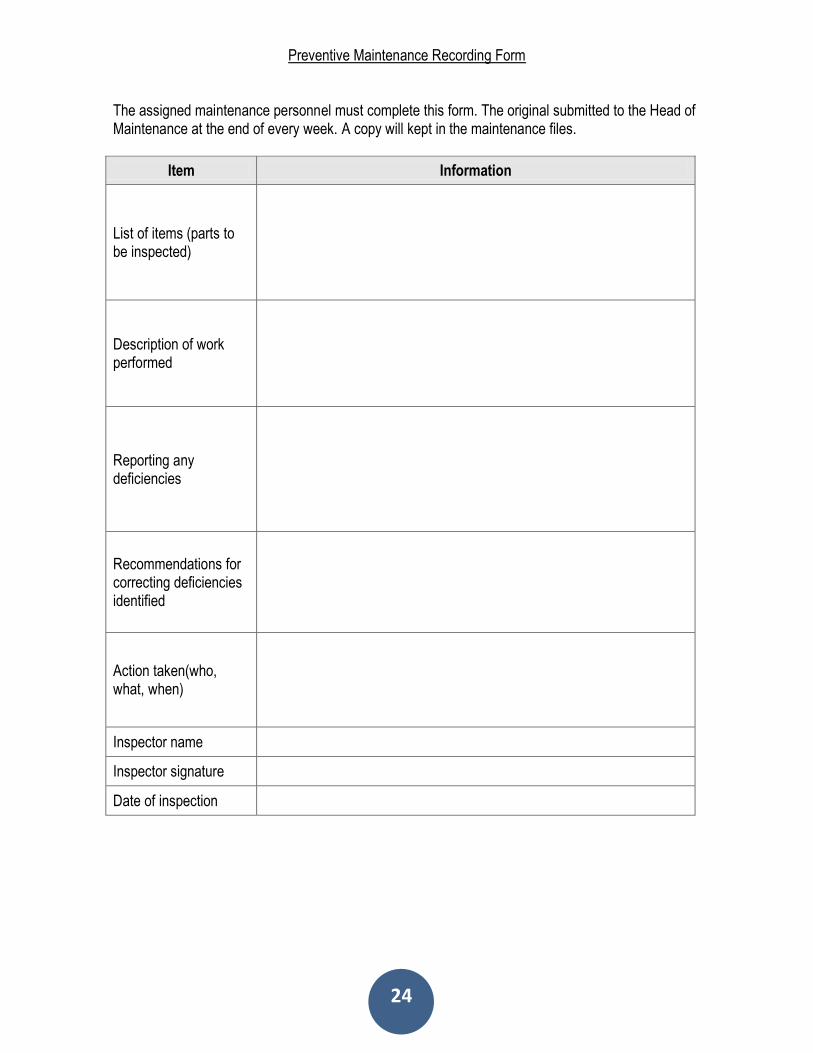
Preventive Maintenance Recording Form
The assigned maintenance personnel must complete this form. The original submitted to the Head of Maintenance at the end of every week. A copy will kept in the maintenance files.
Item Information
List of items (parts to be inspected)
Description of work performed
Reporting any deficiencies
Recommendations for correcting deficiencies identified
Action taken(who, what, when)
Inspector name
Inspector signature
Date of inspection

25
Maintenance Service Log
Date Equipment Service Performed Performed By
26
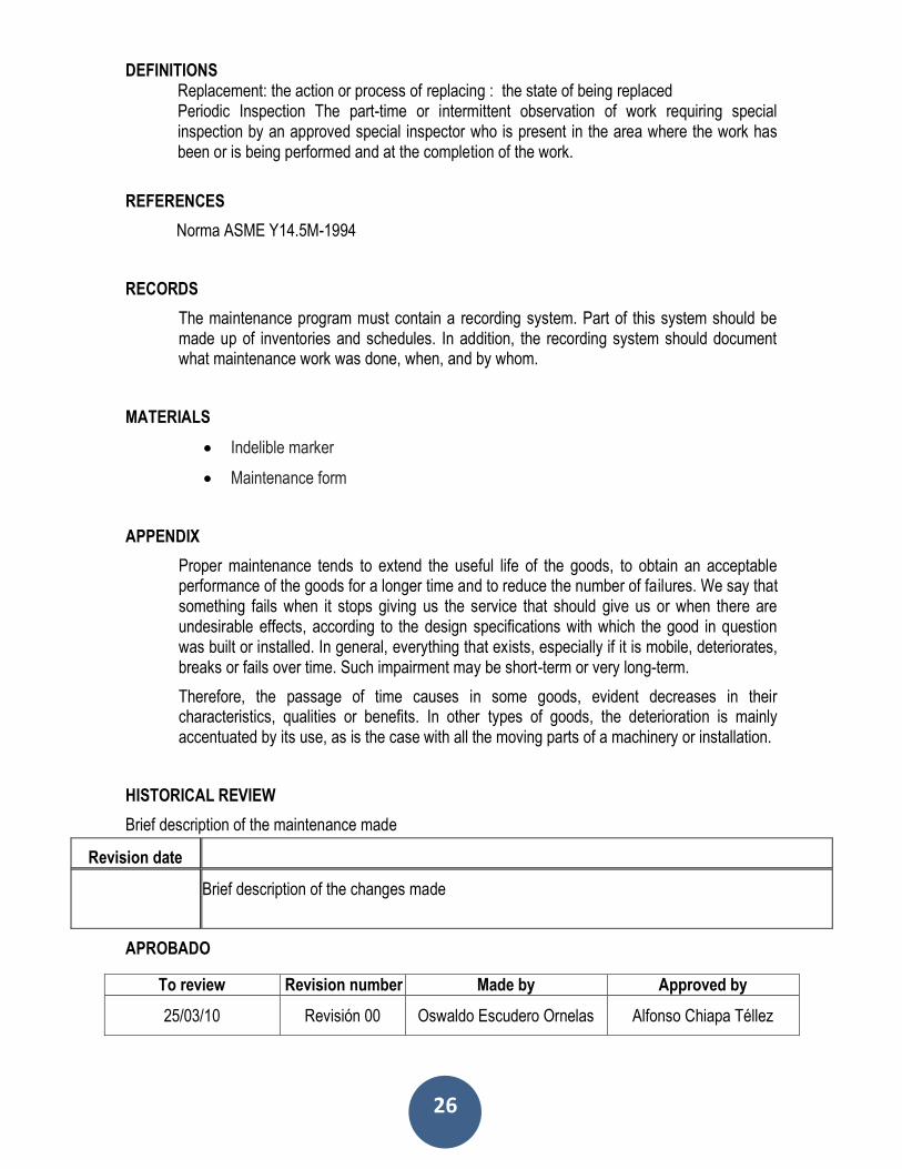
DEFINITIONS Replacement: the action or process of replacing : the state of being replaced Periodic Inspection The part-time or intermittent observation of work requiring special inspection by an approved special inspector who is present in the area where the work has been or is being performed and at the completion of the work.
REFERENCES
Norma ASME Y14.5M-1994
RECORDS
The maintenance program must contain a recording system. Part of this system should be made up of inventories and schedules. In addition, the recording system should document what maintenance work was done, when, and by whom.
MATERIALS
Indelible marker
Maintenance form
APPENDIX
Proper maintenance tends to extend the useful life of the goods, to obtain an acceptable performance of the goods for a longer time and to reduce the number of failures. We say that something fails when it stops giving us the service that should give us or when there are undesirable effects, according to the design specifications with which the good in question was built or installed. In general, everything that exists, especially if it is mobile, deteriorates, breaks or fails over time. Such impairment may be short-term or very long-term.
Therefore, the passage of time causes in some goods, evident decreases in their characteristics, qualities or benefits. In other types of goods, the deterioration is mainly accentuated by its use, as is the case with all the moving parts of a machinery or installation.
HISTORICAL REVIEW
Brief description of the maintenance made
APROBADO
Revision date
Brief description of the changes made
To review Revision number Made by Approved by
25/03/10 Revisión 00 Oswaldo Escudero Ornelas Alfonso Chiapa Téllez

27
MANUAL DEL DISPOSITIVO
DE MEDICIÓN
FIXTURE AND GAGE
6. CONCLUSIONS In conclusion, the project that we had done has contributed in a very important way to the
development of control devices in which we finished the execution and manufacture of an instruction
for the use of the device. This project leaves us many important things that reflect on the quality of a
product. Within the points that we consider to be more important for the Project is the real needs of
the people who work day by day with the control devices and how to make easier this process of
quality.
7. LEARNED LESSONS
In terms of learning, it has been significant since teamwork, learning to know the skills of each
member and get the best of each person, in addition to gaining knowledge of metrology, automotive
parts design, in this case the design Of the dashboard of a Chevy, and consequently the design of
the device to measure that piece, developing the creativity for the manufacture of the device.
An important point has also been the fact of being a multidisciplinary team, because with the
knowledge of both careers has been able to work to meet the project objective.
8. BIBLIOGRAPHY
[1] BENTLEY J. Sistemas de Medición, Principios y Aplicaciones. Editorial CECSA. México (2000) [2] DOEBELIN E. Measurment Systems Aplication and Design. Editorial McGRAW-HILL. Japan (1975). [3] GARCÍA A. Tolerancias, Ajustes y Calibres. Editorial URMO. España (1969). [4] GONZÁLEZ C. ZELENY R. Metrología. Editorial McGRAW-HILL. México (1998). [5] HOLZBOCK W. Instrumentos para Medición y Control. Editorial CECSA. México (1974). [6] Norma ASME Y14.5M-1994 Consulta en línea. Disponible en http://www.dgpengshun.com/uploadfile/2015/0402/20150402103816482.pdf

28