Manual de Sudura PDH
13
www.PDHcenter.com PDH Course S150 www.PDHonline.org Page 1 of 13 Structural Steel Welding Semih Genculu, P.E. Course Content Arc welding requires striking a low-voltage, high-current arc bet ween an electrode and the workpiece. The intense heat generated w ith this arc melts the base metal and allows the joining of two components. The characteristic of the metal that is being welded and the jo int type dictates the welding parameters and the procedure that needs to be followed to obtain a sound weld joint. Typical Arc Welding Processes: Shielded metal arc welding (SMAW): Shielded metal arc welding, which is also known as stick welding, is the most widely used process. The arc is struck between the metal to be welded and a flux coated consumable electrode. The molten flux (slag) covers the hot weld deposit and protects it from the environment. SMAW Process Gas metal arc welding (GMAW): This process is also referred to as metal inert-gas (MIG) welding uses an unc oated continuous wire. The weld area is shielded from contamination by the gas that is fed through the welding torch. The mode of metal transfer (spray, glo bular, short-circuiting, pulsed-arc) is varied by adjusting the amperage and the shielding gases used depending on the welding position and the type of joint.
-
Upload
stan-adrian -
Category
Documents
-
view
254 -
download
1
Transcript of Manual de Sudura PDH

7/26/2019 Manual de Sudura PDH
http://slidepdf.com/reader/full/manual-de-sudura-pdh 1/13
www.PDHcenter.com PDH Course S150 www.PDHonline.org
Page 1 of 13
Structural Steel Welding
Semih Genculu, P.E.
Course Content
Arc welding requires striking a low-voltage, high-current arc between an electrode and theworkpiece. The intense heat generated with this arc melts the base metal and allows the joining of two components. The characteristic of the metal that is being welded and the jointtype dictates the welding parameters and the procedure that needs to be followed to obtain asound weld joint.
Typical Arc Welding Processes:
Shielded metal arc welding (SMAW): Shielded metal arc welding, which is also known asstick welding, is the most widely used process. The arc is struck between the metal to bewelded and a flux coated consumable electrode. The molten flux (slag) covers the hot welddeposit and protects it from the environment.
SMAW Process
Gas metal arc welding (GMAW): This process is also referred to as metal inert-gas (MIG)welding uses an uncoated continuous wire. The weld area is shielded from contamination bythe gas that is fed through the welding torch. The mode of metal transfer (spray, globular,short-circuiting, pulsed-arc) is varied by adjusting the amperage and the shielding gases useddepending on the welding position and the type of joint.

7/26/2019 Manual de Sudura PDH
http://slidepdf.com/reader/full/manual-de-sudura-pdh 2/13
www.PDHcenter.com PDH Course S150 www.PDHonline.org
Page 2 of 13
GMAW Process
Flux-cored arc welding (FCAW): The shielding gases and slag are provided by the
decomposing flux that is contained within the electrode. Auxiliary shielding is also used incertain instances where deeper penetration is needed.
Gas tungsten arc welding (GTAW): Also known as tungsten inert-gas (TIG), the processuses a non-consumable electrode. The shielding gas is again fed through the welding torch.Welding may be accomplished without the addition of filler metal, which is advantageousespecially for thin walled parts.
GTAW Process
Shielding gases:
The primary purpose of the shielding gas is to protect the molten weld from contamination anddamage by the surrounding atmosphere. Although plain inert gases may not be suitable for

7/26/2019 Manual de Sudura PDH
http://slidepdf.com/reader/full/manual-de-sudura-pdh 3/13
www.PDHcenter.com PDH Course S150 www.PDHonline.org
Page 3 of 13
all applications, mixtures with reactive gases (i.e. oxygen, nitrogen, hydrogen and carbondioxide) in controlled quantities will produce stable and relatively spatter-free metal transfer.
Argon: Argon by itself is frequently used for MIG welding of nonferrous metals. A mixture of argon and oxygen or argon and carbon dioxide is usually preferred for ferrous metals. Thehigh-density arc that is created by argon permits the energy to go into the work piece as heatresulting in a narrow bead width with deep penetration.
Helium: has higher thermal conductivity and arc voltage than argon, which causes it toproduce broader weld beads. Because helium is a very light gas, higher flow rates must beused for effective shielding. This characteristic is beneficial in overhead welding.
Carbon dioxide: is widely used for steels. Higher welding speed, better joint penetration andsound deposits with good mechanical properties can be achieved. Carbon dioxide is not aninert gas as the argon and helium and breaks down into carbon monoxide and free oxygenunder the heat of the arc. The oxygen is used to superheat the weld metal transferring acrossthe arc.
Arc welding defects:
Most welds contain defects. The question is to determine if they are significant consideringthe application. Sometimes discontinuities that may not affect mechanical properties mayreduce corrosion performance. The heat-affected zone (HAZ) is the main consideration whenevaluating the soundness of the weld joint. The HAZ may be considered as a discontinuitybecause of the metallurgical alterations that may occur as a result of the welding heat. Graingrowth, phase transformations, formation of precipitates or overaging (degradation of heattreat properties in precipitation hardened alloys) all has a drastic effect on the properties of theHAZ.
Porosi ty : gas pockets or voids that are found in welds
Causes Remedies
Excessive hydrogen, nitrogen or oxygen in welding atmosphere
Use low hydrogen welding process, filler metals high in deoxidizers, increase shieldinggas flow
High solidification rate Use preheat or increase heat input
Dirty base metal Clean joint faces and adjacent surfaces
Dirty filler wire Use clean wire and store fillers in a clean area
Improper arc length, welding current or
electrode manipulation
Modify welding parameters and techniques
Volatilization of zinc from brass Use copper-silicon filler, reduce heat input
Galvanized Steel Use E7010 electrode and manipulate the archeat to volatilize the galvanizing (zinc) aheadof the molten weld pool
Excessive moisture in electrodecovering or on joint surfaces
Use recommended procedures for baking andstoring electrodes, preheat base metal
High sulfur base metal Use electrodes with basic slagging reactions

7/26/2019 Manual de Sudura PDH
http://slidepdf.com/reader/full/manual-de-sudura-pdh 4/13
www.PDHcenter.com PDH Course S150 www.PDHonline.org
Page 4 of 13
Macrograph showing porosity
Slag inc lus ions: The oxides or other nonmetallic inclusions that become entrapped in theweld metal. They may be caused by contamination or inadequate cleaning between weldpasses. The slag derived from fluxes employed during welding needs to be cleaned in multipass operations.
Tungsten inc lus ions: In the TIG process the touching of the electrode to the weld metal maycause transfer of the tungsten particles into the weld metal.
Inadequate penetration: When the actual penetration of a weld into the base metal is lessthan specified in the design, the discontinuity is called inadequate or lack of penetration. Thiscondition may result from improper joint design, insufficient welding heat, incorrect bevel angleor poor control of the welding arc. Macrograph below shows the lack of root penetration in afillet weld.
Macrograph showing lack of root penetration
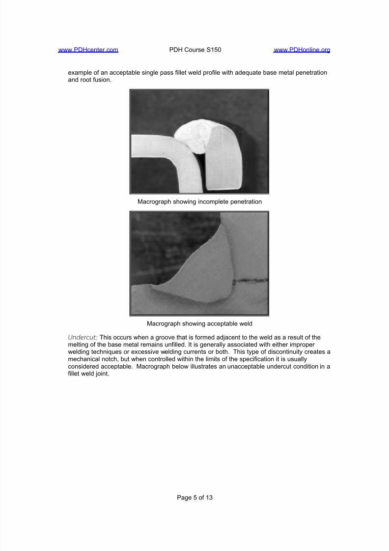
Incomplete fusion: Lack of fusion occurs when the weld and base metal fail to adequatelyfuse together. It may be caused by not raising the temperature of the base metal or previouslyapplied weld metal to the melting point or failure to remove the slag or mill scale. Theshielding gas can also influence the penetration; Typically helium is added for nonferrousmetals and carbon dioxide is added for ferrous metals (to argon) to increase penetration. Thefirst macrograph below shows incomplete penetration whereas the second illustration is for an
7/26/2019 Manual de Sudura PDH
http://slidepdf.com/reader/full/manual-de-sudura-pdh 5/13
www.PDHcenter.com PDH Course S150 www.PDHonline.org
Page 5 of 13
example of an acceptable single pass fillet weld profile with adequate base metal penetrationand root fusion.
Macrograph showing incomplete penetration
Macrograph showing acceptable weld
Undercut : This occurs when a groove that is formed adjacent to the weld as a result of themelting of the base metal remains unfilled. It is generally associated with either improper welding techniques or excessive welding currents or both. This type of discontinuity creates amechanical notch, but when controlled within the limits of the specification it is usuallyconsidered acceptable. Macrograph below illustrates an unacceptable undercut condition in afillet weld joint.

7/26/2019 Manual de Sudura PDH
http://slidepdf.com/reader/full/manual-de-sudura-pdh 6/13
www.PDHcenter.com PDH Course S150 www.PDHonline.org
Page 6 of 13
Macrograph showing undercut
Weld profi le: The profile of a finished weld may have a considerable effect on theperformance under dynamic loading conditions. Overlap, excessive reinforcement or mismatch can provide stress concentration points where fatigue cracks can initiate. Typicalunacceptable butt and fillet weld profiles are shown below along with an example of poor fit-up(mismatch):
Macrograph showing poor fit-up (butt weld)

7/26/2019 Manual de Sudura PDH
http://slidepdf.com/reader/full/manual-de-sudura-pdh 7/13
www.PDHcenter.com PDH Course S150 www.PDHonline.org
Page 7 of 13
Arc str ikes: They are caused by the unintentional melting of the base metal outside the welddeposit area by the welding arc. It can create localized hard or soft spots, cracking or undercut. Any cracks or blemishes caused by arc strikes should be ground to a smooth
contour.
Cracks: Cracks occur in weld or base metal when localized stresses exceed the ultimatestrength of the metal. They are often associated with mechanical or metallurgical stressconcentration points. Cracks can be classified as hot or cold cracks. Hot cracks develop atelevated temperatures during solidification. Cold cracks (or sometimes referred to as delayedcracks) develop after solidification. Hot cracks propagate between grains (intergranular) coldcracks propagate both between and through the grains (inter and transgranular cracks).
Surface cracks on a weld bead
Micrograph showing intergranular cracking

7/26/2019 Manual de Sudura PDH
http://slidepdf.com/reader/full/manual-de-sudura-pdh 8/13
www.PDHcenter.com PDH Course S150 www.PDHonline.org
Page 8 of 13
Macrograph showing cracks in the HAZ
Cracks: Hot cracks, cold cracks or microfissures can form in the weld or in the base metal
Causes Remedies
Highly rigid jointPreheatRelieve residual stresses mechanicallyMinimize shrinkage stresses using backstepsequence
Excessive dilution (i.e. the change inchemical composition of the depositedweld caused by the admixture of the
base metal or previous weld bead)
Change welding current and travel speedWeld with covered electrode negative; butter the joint faces prior to welding (buttering is todeposit surfacing metal to providemetallurgically compatible weld for thesubsequent passes)
Poor fit-up Reduce root opening
Small weld bead Increase electrode size, raise welding current,reduce travel speed
High sulfur base metal Use filler metal low in sulfur
Excessive distortion Change to balanced welding on both sides of joint
Crater cracking Fill crater before extinguishing the arc
High residual stresses Redesign weldment, change weldingsequence, apply intermediate stress relief
High hardenability Preheat, increase heat input, heat treatwithout cooling to room temperature

7/26/2019 Manual de Sudura PDH
http://slidepdf.com/reader/full/manual-de-sudura-pdh 9/13
www.PDHcenter.com PDH Course S150 www.PDHonline.org
Page 9 of 13
Photograph illustrating crater cracking resulting from abrupt weld termination (MIG process, aluminum weld)
The effect of carbon equivalent:
The final metallurgical structure of the weld zone is determined by the type of steel and thecooling rate. The cooling rate is very important when heat-treatable (hardenable) steels areinvolved. Increasing the initial temperature of the base metal being welded has the effect of reducing the cooling rate. Preheat is often used for this purpose. The carbon equivalent(C.E.) may be considered as the main factor in estimating preheat need. Generally, thehigher the carbon content of a steel, the greater the tendency to form a hard and brittle HAZ.This necessitates the use of preheat and low hydrogen electrodes. Carbon, however, is notthe only element that influences hardenability. Other elements in steel also are responsible for the hardening and loss of ductility that occur with rapid cooling. One of the various empiricalformulas used to determine carbon equivalent is given in the Structural Steel Welding Code(AWS D1.1) as follows:
%C.E.= %C + % (Mn+Si)/6+ % (Cr+Mo+V)/5 + % (Ni+Cu)/15
The approximate recommended preheat temperatures based on C.E. are:
For up to 0.45%…………preheat is optional
0.45-0.60%………………200-400ºF
Over 0.60%……………....400-700ºF
Usually a steel that requires preheating must also be kept at this temperature between weldpasses. The heat input of the welding process is adequate to maintain the required interpasstemperature on most weldments. On massive components this may not be the case and torch
heating between passes may be required. Since the purpose of preheating is to reduce thequench rate, the same slow cooling rate must be accomplished for all passes.
Besides the widely used carbon equivalent criteria, the following factors should also beconsidered when determining the need for preheat/post weld heat treat: code requirements,section thickness, restraint, ambient temperature, filler metal hydrogen content and previouscracking problems.
AWS Classifications:
The American Welding Society numbering system tells a lot about the properties and usabilityof the electrode. Using the stick electrode numbering system as a representative example:

7/26/2019 Manual de Sudura PDH
http://slidepdf.com/reader/full/manual-de-sudura-pdh 10/13
www.PDHcenter.com PDH Course S150 www.PDHonline.org
Page 10 of 13
The prefix “E” designates an arc-welding electrode. The first two digits of a four-digit number and the first three digits of a five-digit number indicate tensile strength. For example, E7018 isa 70,000-psi tensile strength electrode while E10018 designates a 100,000-psi one.
The next to last digit indicates the position. 1 is for all position, 2 is for flat and horizontal and 3is for flat, horizontal, vertical down and overhead. The last two digits together are for a“usability” rating which indicates the type of electrode coating and the correct polarity to use. An example would be “18” for iron powder, low hydrogen with AC or DC+.
Weld Symbols:
When welds are specified on fabrication drawings a set of symbols are used to describe thetype and size of the weld. They can typically be described as a simplified cross section of theactual weld. Some representative symbols are shown below. A complete set of symbols isgiven in a standard published by the American Welding Society.
A welding symbol, on the other hand, includes a weld symbol and supplementary informationsuch as the arrow, dimensions, finish symbols, specification and process. The basic elements
of a welding symbol are shown below along with several examples.

7/26/2019 Manual de Sudura PDH
http://slidepdf.com/reader/full/manual-de-sudura-pdh 11/13
www.PDHcenter.com PDH Course S150 www.PDHonline.org
Page 11 of 13
Standard location of elements of a welding symbol

7/26/2019 Manual de Sudura PDH
http://slidepdf.com/reader/full/manual-de-sudura-pdh 12/13
www.PDHcenter.com PDH Course S150 www.PDHonline.org
Page 12 of 13
Weld Qualifications:
Most fabrication documents require qualification of welding procedures and welders. AWSCode D1.1 is the governing document for structural steel welding. A welding procedurespecification (WPS) provides detail welding conditions for a specific application containing theessential variables that require requalification of procedures when the variables are changedbeyond specified limits. Typical weld procedures should, at a minimum, contain informationabout the base materials that are to be welded, the welding process, the filler metaldesignation, type of current and range, arc voltage and travel speed, joint design andtolerances, surface preparation, positions of welding, preheat and interpass temperatures,interpass cleaning and post weld heat treat as needed.

7/26/2019 Manual de Sudura PDH
http://slidepdf.com/reader/full/manual-de-sudura-pdh 13/13
www.PDHcenter.com PDH Course S150 www.PDHonline.org
Page 13 of 13
Groove and fillet weld positions
Actual welding parameters used to produce an acceptable test joint and the results of thequalification tests (typically x-ray, tensile and bend) are documented in a procedurequalification record (PQR). Welders are required to demonstrate their ability to produce soundwelds by submitting coupons that are either radiographed or mechanical tested to obtainwelder performance qualifications (WPQ). Welders are also required to be qualified within thedefined limits of each position (e.g. flat welding test does not qualify the welder for performingvertical or overhead welding).