Manual - Darley
18
. Copyright @ Controls, Inc P.O. Box 368 • Sharon Center, OH 44274 Phone 330.239.4345 • Fax 330.239.2845 • www.controlsinc.com Product Manual Pump Display & Control Panel Mechanical Engines Part Number: MVP-M1104 Revision: 1.0
Transcript of Manual - Darley

.
Copyright @ Controls, Inc
P.O. Box 368 • Sharon Center, OH 44274
Phone 330.239.4345 • Fax 330.239.2845 • www.controlsinc.com
Product Manual
Pump Display & Control Panel Mechanical Engines
Part Number: MVP-M1104 Revision: 1.0

CONTROLS, INCORPORATED
C O N T R O L S Y S T E M S & S O L U T I O N S
2
TABLE OF CONTENTS
PANEL INFORMATION…………………………………………………………………………………………………………………………….3
ACTUATOR CALIBRATION PANEL CONNECTORS
MVP-704R MODULE………………………………………………………………………………………………………………………………….5
INSTALLATION INFORMATION……...........………………………………….………………………………………………....5
MODULE CONNECTOR ……...................………………………...………………………………………………………………….6
ENGINE ALARMS, CODES AND MESSAGES…………………………………………………………….…...……..7
ALARM ANNUNCIATION AND CODE READER PANEL INDICATION LAMPS
CONTROL PANEL ANALOG AND DIGITAL INPUTS…………………………………………..……………..…9
CONTROL PANEL OUTPUTS…………………………………………………………………………………………………..10
MENU SYSTEM……………………………………………………………….………………..…………………………..……….…..…11
MENU ACCESS, EXIT AND NAVIGATION MENUS TO VIEW INFORMATION MENUS TO CONFIGURE MODULE SETTINGS
MSG-104R MODULE……………………………………………………………………………………………………………………………….16
MODULE CONNECTOR ……...................………………………...……………………….……………………………………….16
CONTROL PANEL ANALOG AND DIGITAL INPUTS…………………………………………..…………..…17
MENU SYSTEM……………………………………………………………….………………..…………………………….…….…..…18
MENU ACCESS, EXIT AND NAVIGATION MENUS TO VIEW INFORMATION MENUS TO CONFIGURE MODULE SETTINGS

CONTROLS, INCORPORATED
C O N T R O L S Y S T E M S & S O L U T I O N S
3
PANEL INFORMATION
J1939 Mechanical Actuator Calibration
Prior to operation, the J1939 Actuator requires calibration with the MVP-704. This will require
the following steps:
With the engine running, go to the Throttle Configuration Menu
Press up arrow until the screen displays Calibrate Actuator. Change to Yes.
Adjust the engine speed to the desired minimum speed and press enter for yes.
Adjust the engine speed to the desired maximum speed and press enter for yes
Press enter to save the change
Recycle Power
MVP-704
Throttle
Power Switch
Note: switches for the main
and remote panels must be
in alternate positions for
active power.
Pump Primer Start/Stop
MSG-104

CONTROLS, INCORPORATED
C O N T R O L S Y S T E M S & S O L U T I O N S
4
Panel Connectors
Main/Remote Connector –Deutsch 8 pin (DT04-08PA)
Terminating Resistor / Remote Connector –Deutsch 8 pin (DT06-8S)
8 Pin Main/Remote Harness Connector
Pin Function
1 Battery Positive
2 Switched B+
3 J1939 High
4 J1939 Low
5 Battery Positive
6 Prime Button
7 Prime Button
8 Battery Negative
8 Pin Terminating /Remote Harness Connector
Pin Function
1 Open
2 Switched B+
3 J1939 High
4 J1939 Low
5 Open
6 Open
7 Open
8 Battery Negative
CONTROLS, INCORPORATED
C O N T R O L S Y S T E M S & S O L U T I O N S
5
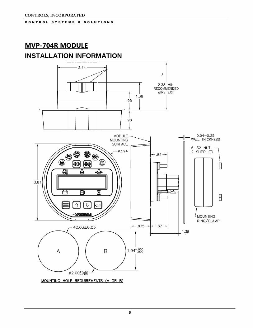
MVP-704R MODULE
INSTALLATION INFORMATION

CONTROLS, INCORPORATED
C O N T R O L S Y S T E M S & S O L U T I O N S
6
MODULE CONNECTOR INFORMATION
BATTERY +
CAN HIGH
CAN LOW
SPEED INPUT
N/A
BATTERY -
BATTERY -
START/STOP INPUT
N/A
N/A
N/A
N/A
N/A
1
2
3
4
5
6
1
2
3
4
5
6
CONTROLS, INCORPORATED
C O N T R O L S Y S T E M S & S O L U T I O N S
7
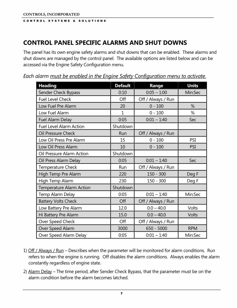
CONTROL PANEL SPECIFIC ALARMS AND SHUT DOWNS
The panel has its own engine safety alarms and shut downs that can be enabled. These alarms and
shut downs are managed by the control panel. The available options are listed below and can be
accessed via the Engine Safety Configuration menu.
Each alarm must be enabled in the Engine Safety Configuration menu to activate.
Heading Default Range Units
Sender Check Bypass 0:10 0:05 – 1:00 Min:Sec
Fuel Level Check Off Off / Always / Run
Low Fuel Pre Alarm 20 0 - 100 %
Low Fuel Alarm 1 0 - 100 %
Fuel Alarm Delay 0:05 0:01 – 1:40 Sec
Fuel Level Alarm Action Shutdown
Oil Pressure Check Run Off / Always / Run
Low Oil Press Pre Alarm 15 0 - 100 PSI
Low Oil Press Alarm 10 0 - 100 PSI
Oil Pressure Alarm Action Shutdown
Oil Press Alarm Delay 0:05 0:01 – 1:40 Sec
Temperature Check Run Off / Always / Run
High Temp Pre Alarm 220 150 - 300 Deg F
High Temp Alarm 230 150 - 300 Deg F
Temperature Alarm Action Shutdown
Temp Alarm Delay 0:05 0:01 – 1:40 Min:Sec
Battery Volts Check Off Off / Always / Run
Low Battery Pre Alarm 12.0 0.0 – 40.0 Volts
Hi Battery Pre Alarm 15.0 0.0 – 40.0 Volts
Over Speed Check Off Off / Always / Run
Over Speed Alarm 3000 650 - 5000 RPM
Over Speed Alarm Delay 0:05 0:01 – 1:40 Min:Sec
1) Off / Always / Run – Describes when the parameter will be monitored for alarm conditions. Run
refers to when the engine is running. Off disables the alarm conditions. Always enables the alarm
constantly regardless of engine state.
2) Alarm Delay – The time period, after Sender Check Bypass, that the parameter must be on the
alarm condition before the alarm becomes latched.

CONTROLS, INCORPORATED
C O N T R O L S Y S T E M S & S O L U T I O N S
8
Indicator Lamps .
Engine Fault Lamp
Engine Alarm Lamp

CONTROLS, INCORPORATED
C O N T R O L S Y S T E M S & S O L U T I O N S
9
CONTROL PANEL ANALOG AND DIGITAL INPUTS The panel has one analog input and up to one digital input available to monitor other components, senders or signals. These inputs can be used for a number of purposes including alarms and shut downs.
Input Heading Default Options Connector Pin
Digital 1
Normally Open Open / Closed
B 1 Function Start/Stop
Message None
Check Always Off / Always / Run
Digital Outputs
1) Alarm – Engine shutdown when active with display message as assigned. A red lamp will also
be illuminated.
2) Pre Alarm – Warning message will be displayed along with a yellow lamp when active.
3) Pre Alarm & Alarm - Energizes an external audible alarm when a pre alarm or alarm condition
is present. Pressing the ENTER button will silence.
4) Alarm Horn - Energizes an external audible alarm when an alarm condition is present.
Pressing the ENTER button will silence.
5) Engine Run - Relay will be active when engine RPM is greater than 600. Typically used to
drive an auxiliary circuit such as louvers or send a signal to a monitoring station.
6) Low Oil Press Alarm - Relay closes if a low oil pressure shutdown is detected.
7) High Coolant Temp Alarm - Relay closes if a high engine temperature shutdown is detected.
8) Over Speed Alarm - Relay closes if an over speed shutdown is detected.
9) Over Crank Alarm - Relay closes if an over crank alarm is detected.
10) Low Fuel Level Alarm - Relay closes if a low fuel level shutdown is detected.
11) Fuel / Run - Relay will be active during an engine start request and while the engine is
running.
12) Custom 1 - Reserved for OEM applications.
13) Preheat - Relay will be active during programmed preheat period. Used to drive a preheat
relay.

CONTROLS, INCORPORATED
C O N T R O L S Y S T E M S & S O L U T I O N S
10
Digital Function Activation
1) Off / Always / Run – Describes when the parameter will be monitored for alarm conditions. Run refers to when the engine is running. Off disables the alarm conditions. Always enables the alarm constantly regardless of engine state.
2) Alarm Delay – The time period, after Sender Check Bypass, that the parameter must be on the alarm condition before the alarm becomes latched.
CONTROL PANEL RELAY OUTPUTS The panel has three relay outputs available to signal other devices based on predefined events. These Outputs can be used for a number of purposes including engine operation or driving an audible alarm.
Input Heading Default Connector Pin
Relay 1
B 2 Function None
Polarity Positive
Initial State On
Input Heading Default Connector Pin
Relay 2
B 5 Function None
Polarity Positive
Initial State Off
Input Heading Default Connector Pin
Relay 3
B 6 Function None
Polarity Positive
Initial State Off
CONTROLS, INCORPORATED
C O N T R O L S Y S T E M S & S O L U T I O N S
11
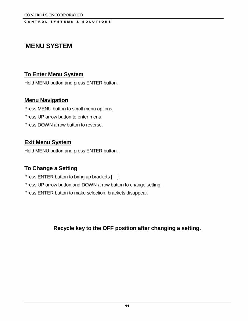
MENU SYSTEM
To Enter Menu System
Hold MENU button and press ENTER button.
Menu Navigation
Press MENU button to scroll menu options.
Press UP arrow button to enter menu.
Press DOWN arrow button to reverse.
Exit Menu System
Hold MENU button and press ENTER button.
To Change a Setting
Press ENTER button to bring up brackets [ ].
Press UP arrow button and DOWN arrow button to change setting.
Press ENTER button to make selection, brackets disappear.
Recycle key to the OFF position after changing a setting.

CONTROLS, INCORPORATED
C O N T R O L S Y S T E M S & S O L U T I O N S
12
Main Menus
Main Menus Sub Menus
Active Engine Fault Codes View/Scroll Active Fault Codes
Stored Engine Fault Codes View/Scroll Stored Fault Codes
Engine Parameters View ECU Engine Information
(% Load, Torque, Oil Temp, etc.)
Emissions Parameters Regen Options (Auto, Inhibit, Request)
DEF Level
Regen Active/Not Active View
Regen Inhibited/Not Inhibited View
DPF Out Gas Temperature View
DPF Differential Pressure View
Engine Identification Engine Model # View
Engine Serial # View
Module Information Control Unit Part# View
Control Unit Software Version View
Controller Setup Quick Setup (1)
(PASSWORD PROTECTED) Engine Parameter Configuration (2)
Input Configuration (3)
Output Configuration (4)
Throttle Configuration (5)
Engine Safety Configuration (6)
Module Configuration (7)
Display Configuration (8)
CAN Configuration (9)
Maintenance Configuration (10)
Emissions Configuration (11)
To access the controller setup menus, a password is required. The password is 4345.
Configuration Menus
Viewing Menus

CONTROLS, INCORPORATED
C O N T R O L S Y S T E M S & S O L U T I O N S
13
Configuration Menus
(1) Quick Setup Multiplex Type (Default = Main Electronic)
Engine Type (Default = Electronic T3)
Engine Manufacturer (Default = John Deere)
TSC Minimum Speed
TSC Min @ Actuator Position %
TSC Maximum Speed
TSC Max @ Actuator Position %
Performance Display
(2) Eng. Parameter Configuration Engine Type
Parameter Selection (Speed, Coolant Temp., Oil Pressure, Fuel
Level, Voltage, Hour Meter)
Parameter Setup (Varies based on parameter)
(3) Input Configuration Configure Selection (Channels/Message)
Digital 1 Setup (Default to Start/Stop)
(4) Output Configuration Configure Selection (Channels/Message)
Relay 1-3 Setup
(5) Throttle Configuration Throttle Type (Default = Momentary)
Cooperative TSC Mode (Default = Remote)
TSC Minimum Speed
TSC Min @ Actuator Position %
TSC Maximum Speed
TSC Max @ Actuator Position %
TSC Bump Speed
TSC Ramp Rate
Throttle Curve
Multi State Speeds 1-4
Speed Limit
Torque Derate Limit
Calibrate Actuator (default = No)

CONTROLS, INCORPORATED
C O N T R O L S Y S T E M S & S O L U T I O N S
14
(6) Engine Safety Configuration Sender Check By-Pass (Default = 0:10)
Parameter Selection (Fuel Level, Oil Pressure, Temperature, Battery,
Over speed, Speed Limit, Derate to Shutdown)
Parameter Settings (vary based on selection)
(7) Module Configuration Preheat Time
Low Power Mode
Power Save Delay
Multiplex Comm Mode
Multiplex Timeout
Pre-Alarms Displayed (Default = 4)
Check Run Criteria
Clear Operation Log (Default = No)
Clear Alarm Log (Default = No)
Clear # of Starts
Engine Run Criteria
Engine Stop Criteria
(8) Display Configuration English/Metric Selection
Performance Display Off/On
Fuel Display
(9) CAN Configuration Engine Manufacturer
TSC1 Address (Default = 3) Others available
Source Address (Default = 44) Others available
Engine Address (Default = 0) Others available
Speed Transmit On/Off
Temperature Transmit On/Off
Oil Pressure Transmit On/Off
Fuel Level Transmit On/Off
Voltage Transmit On/Off
Hours Transmit On/Off
Faults Transmit
(10) Maintenance Configuration Service Messages
Schedule Selection
Schedule Reset
Schedule Interval
Schedule Warning
Schedule Trip
Schedule Message
CONTROLS, INCORPORATED
C O N T R O L S Y S T E M S & S O L U T I O N S
15
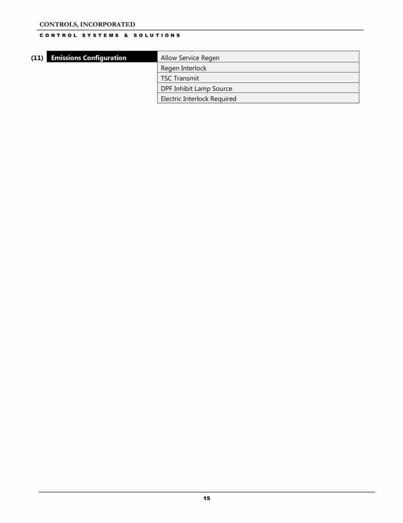
(11) Emissions Configuration Allow Service Regen
Regen Interlock
TSC Transmit
DPF Inhibit Lamp Source
Electric Interlock Required
CONTROLS, INCORPORATED
C O N T R O L S Y S T E M S & S O L U T I O N S
16
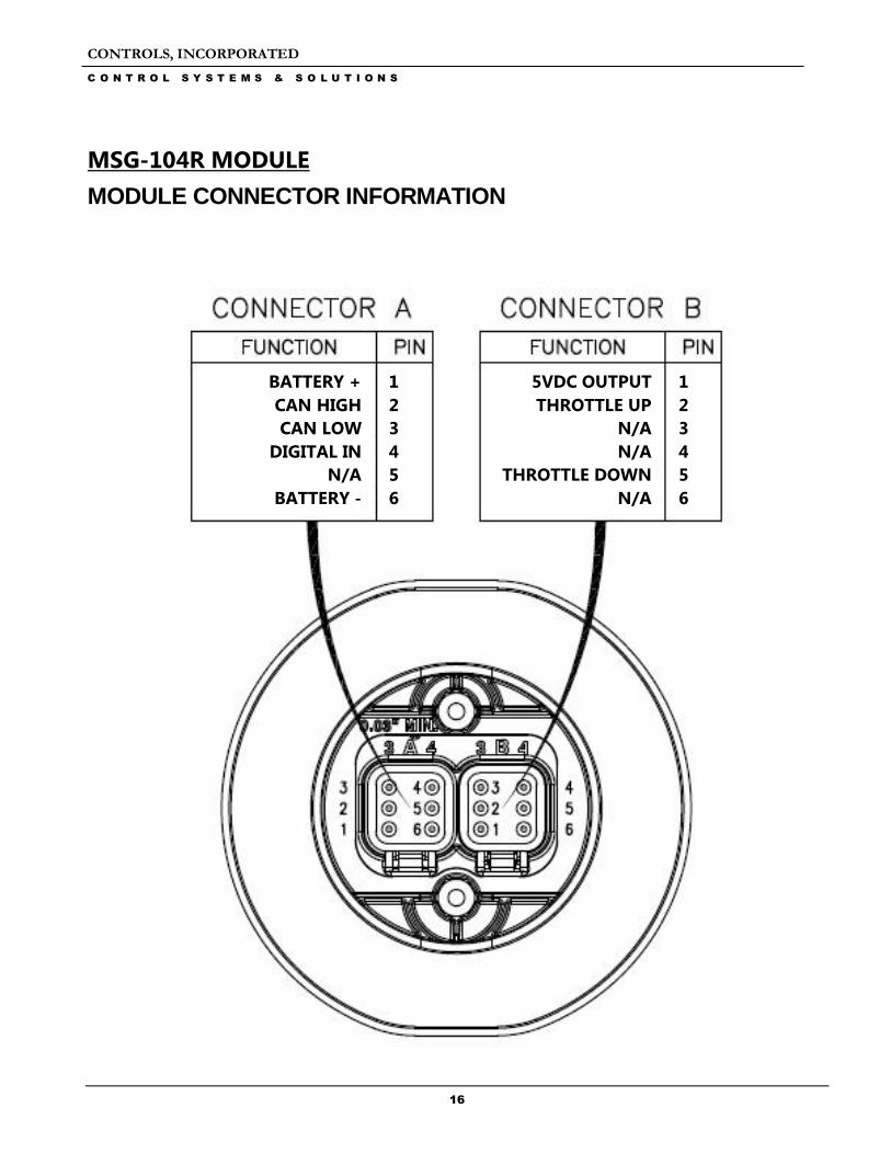
MSG-104R MODULE
MODULE CONNECTOR INFORMATION
BATTERY +
CAN HIGH
CAN LOW
DIGITAL IN
N/A
BATTERY -
BATTERY -
5VDC OUTPUT
THROTTLE UP
N/A
N/A
THROTTLE DOWN
N/A
1
2
3
4
5
6
1
2
3
4
5
6

CONTROLS, INCORPORATED
C O N T R O L S Y S T E M S & S O L U T I O N S
17
CONTROL PANEL ANALOG AND DIGITAL INPUTS The panel has four digital input available to monitor other components, senders or signals. These inputs can be used for a number of purposes including alarms and shut downs.
Input Heading Default Options Connector Pin
Digital 1
Normally Open Open / Closed
A 4 Function None
Message None
Check Always Off / Always / Run
Digital 2
Normally Open Open / Closed
B 2 Function Throttle Up
Message None
Check Always Off / Always / Run
Digital 3
Normally Open Open / Closed
B 5 Function Throttle Down
Message None
Check Always Off / Always / Run
Digital 6
Normally Open Open / Closed
A 5 Function None
Message None
Check Always Off / Always / Run

CONTROLS, INCORPORATED
C O N T R O L S Y S T E M S & S O L U T I O N S
18
MENU SYSTEM
Main Menus
Main Menus Sub Menus
Alarm Event Log View/Scroll Logged Alarms (32 max)
Module Information Control Unit Part# View
Control Unit Software Version View
Controller Setup Pressure Configuration (1)
(PASSWORD PROTECTED) Input Configuration (2)
Pressure Safety Configuration (3)
CAN Configuration (4)
To access the controller setup menus, a password is required. The password is 4345.
Configuration Menus
(1) Pressure Configuration Parameter
Pressure Source
Pressure Input Channel
Pressure Minimum
Pressure Maximum
Current Pressure
Zero Trim Calibration
(2) Input Configuration Configure Selection (Channels/Message)
Digital 1-4 Setup
(3) Pressure Safety Configuration Pressure Check (Default = Off)
Low Pressure Pre Alarm @ (Default = 0 psi)
Low Pressure Alarm @ (Default = 0 psi)
High Pressure Pre Alarm @ (Default = 500 psi)
High Pressure Alarm @ (default = 500 psi)
Pressure Alarm Delay (Default = 0:05)
Pressure Hysteresis (Default = 5 psi)
(4) CAN Configuration Pressure Transmit
Configuration Menus
Viewing Menus