Manual Cooler CNPS9500A LED
9
User’s Manual CNPS9500A LED www.ZALMAN.com Ver.150811 Intel Socket 1155/1156/1151/1150/775 CPUs AMD Socket FM2/FM1/AM3+/AM3/AM2+/AM2 CPU & APUs To ensure safe and easy installation, please read the following precautions.
description
Manual Cooler CNPS9500A LED
Transcript of Manual Cooler CNPS9500A LED

User’s ManualCNPS9500A LED
www.ZALMAN.com
Ver.150811
Intel Socket 1155/1156/1151/1150/775 CPUsAMD Socket FM2/FM1/AM3+/AM3/AM2+/AM2 CPU & APUs
To ensure safe and easy installation,please read the following precautions.
1.COM
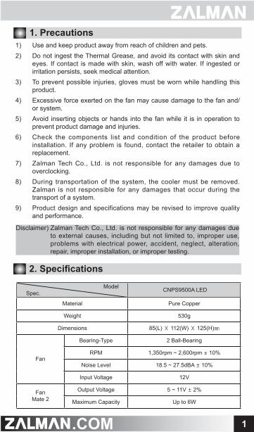
2. Specifications
ModelSpec. CNPS9500A LED
Material Pure Copper
Weight 530g
Dimensions 85(L) Ⅹ 112(W) Ⅹ 125(H)㎜
Fan
Bearing-Type 2 Ball-Bearing
RPM 1,350rpm ~ 2,600rpm ± 10%
Noise Level 18.5 ~ 27.5dBA ± 10%
Input Voltage 12V
FanMate 2
Output Voltage 5 ~ 11V ± 2%
Maximum Capacity Up to 6W
1. Precautions1) Use and keep product away from reach of children and pets.2) Do not ingest the Thermal Grease, and avoid its contact with skin and
eyes. If contact is made with skin, wash off with water. If ingested or irritation persists, seek medical attention.
3) To prevent possible injuries, gloves must be worn while handling this product.
4) Excessive force exerted on the fan may cause damage to the fan and/ or system.
5) Avoid inserting objects or hands into the fan while it is in operation to prevent product damage and injuries.
6) Check the components list and condition of the product before installation. If any problem is found, contact the retailer to obtain a replacement.
7) Zalman Tech Co., Ltd. is not responsible for any damages due to overclocking.
8) During transportation of the system, the cooler must be removed. Zalman is not responsible for any damages that occur during the transport of a system.
9) Product design and specifications may be revised to improve quality and performance.
Disclaimer) Zalman Tech Co., Ltd. is not responsible for any damages due to external causes, including but not limited to, improper use, problems with electrical power, accident, neglect, alteration, repair, improper installation, or improper testing.
2.COM
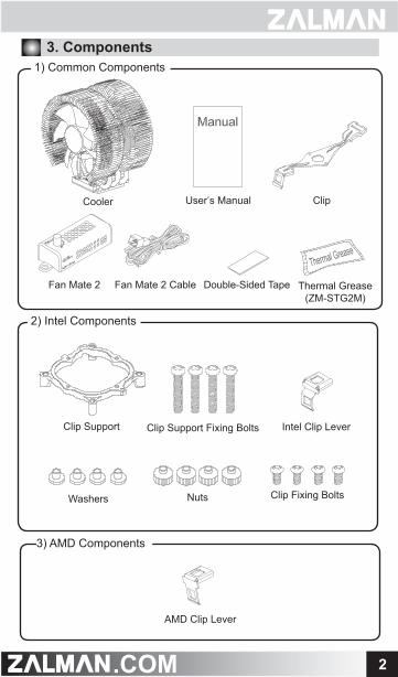
1) Common Components3. Components
Clip Support Fixing Bolts
AMD Clip Lever
Clip Support
User’s Manual Clip
Washers Nuts
Intel Clip Lever
Clip Fixing Bolts
Cooler
2) Intel Components
3) AMD Components
Thermal Grease(ZM-STG2M)
Fan Mate 2 CableFan Mate 2 Double-Sided Tape

3.COM
4. Installation Requirements1) Space Requirements
2) Air Guide Removal
3) Cooler Orientation
The cooler’s installation requires unobstructed space with dimensions of 155㎜(width), 88㎜(length), 128㎜(height), and the CPU as a central reference point. Please check if components such as ODDs and PSU protrude into the required space.
Air guides on enclosures must be removed, before the cooler’s installation, forthey protrude into the cooler’s required space.
It is recommended that the cooler be installed so that air flows from the cooler toward the enclosure’s rear exhaust fan.
88㎜
128㎜
115㎜
PSU

4.COM
4) Installation Based On Clip OrientationA. Horizontal Clip Orientation
B. Vertical Clip Orientation
5.COM
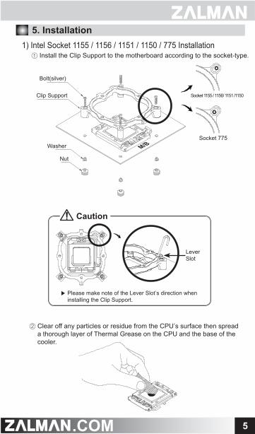
② Clear off any particles or residue from the CPU’s surface then spread a thorough layer of Thermal Grease on the CPU and the base of the cooler.
1) Intel Socket 1155 / 1156 / 1151 / 1150 / 775 Installation① Install the Clip Support to the motherboard according to the socket-type.
5. Installation
Nut
Washer
Bolt(silver)
Clip Support
M/B
Socket 1155 / 1156/ 1151 /1150
Socket 775
▶ Please make note of the Lever Slot’s direction when installing the Clip Support.
Caution
Lever Slot

6.COM
② Refer to page 4 ‘Installation Based On Clip Orientation’ and position the Clip over the cooler’s Base Cover.
2) AMD Socket FM2/FM1/AM3+/AM3/AM2+/AM2 Installation① Clear off any particles or residue from the CPU’s surface then spread
a thorough layer of Thermal Grease on the CPU and the base of the cooler.
④ Insert the Intel Clip Lever into the Clip’s Lever Slot then hook on the Clip’s opposite end onto the Lug marked with the arrow head. Press down the Clip Lever and hook on the Clip Lever onto its Lug.
⑤ Refer to Section 6 ‘Fan Mate 2 Installation and Usage’ for instructions on power connection.
③ Refer to page 4 ‘Installation Based On Clip Orientation’ and position the Clip over the cooler’s Base Cover.

7.COM
③ Insert the AMD Clip Lever into the Clip’s Lever Slot then hook on the Clip’s opposite end onto its Lug. Press down on the Clip Lever and hook on the Clip Lever onto its Lug.
④ Refer to Section 6 ‘Fan Mate 2 Installation and Usage’ for instructions on power connection.
① Connect Fan Mate 2 between the Fan Cable and the motherboard as shown in the diagram below.
② Fan Mate 2 can be installed to the side of the case using Double-Sided Tape.
M/B
Fan Connector (Cooler)
Double-Sided Tape
6. Fan Mate 2 Installation and Usage1) Fan Mate 2 Installation

8.COM
2) Fan Mate 2 OperationAdjust the Fan Speed Control Knob for RPM control.
Fan Speed Control Knob
In the case that you get a BIOS error beep: ① Rotate the Fan Speed Control Knob clockwise to the maximum setting. ② Disable CPU Fan Detected in BIOS setting or set the system monitoring
program’s CPU Fan RPM to the lowest setting.
※ Certain motherboards will not boot if the CPU fan’s RPM is not detected. In this case inquire to the motherboard’s manufacturer for additional details.
BIOS Booting Error