
Manual - Clayton Prints, Heat Press, Vinyl Cutter for Sale … vinyl cutter...Take the side stands...
16
1 PixMax™ Vinyl Cutter Instruction Manual
Transcript of Manual - Clayton Prints, Heat Press, Vinyl Cutter for Sale … vinyl cutter...Take the side stands...

1
PixMax™ Vinyl Cutter Instruction
Manual

2
Inventory
Here is a list of items you will receive with your vinyl cutter:
Product components (Fig.1-4):
1x Cutter head unit complete with motor, plastic blade grip, optical eye, built in metal roller, 3 adjustable rubber wheel components, USB port and COM port, power socket, on/off switch and measurement strip
2x Vinyl roller bars
1x Aluminium support plate with PixMax™ branding
2x Aluminium roller plates with roller supports
2x Aluminium side stands
2x Base plates with 2 caster wheels on each plate already assembled
Fixtures and Fittings:
6x Small screws
10x Large screws
6x Bolts with threaded bolt caps
6x Black plastic screw cases
6x Black plastic caps
Cables and Plugs:
1x 3 pin power plug
1x USB 2.0 cable
1x 9 pin serial cable
Accessories:
1x Dust cover
1x Mini disc
1x Spare fuse
1x Allen key
1x Blade case containing 3x Blades with safety caps
1x Blade assembly with black plastic case
1x Biro pen connection
Product Inventory
Figure 1: Product inventory
Figure 2: Accesories
Figure 3: Fixtures and fittings
Figure 4: Cables and plugs

3
Assembling the Vinyl Cutter
Assembling the Vinyl cutter is quick and easy. Please take time to follow this step by step guide to
building the equipment.
Equipment needed: 1x Phillips screwdriver
Build time: 15 minutes
1. The first step is to screw the aluminium side stands into the aluminium support plate.
For this you require (Fig. 5&6.):
2x Aluminium side stands
1x Aluminium support plate with PixMax™ branding
4x small screws
4x Black plastic screw cases
4x Black plastic caps
Take the side stands and face the flat sides inwards, ensuring that the top
plate (that the head will rest on) is at the top. On the side facing outwards, locate the
lowest two holes, positioned vertically in line in the middle of the stand. Insert the
small screws into the black plastic screw cases and screw them through the hole
in the case. These cases will help guide the screw into place and hold it whilst
you screw the support plate in. Insert the cases into the two holes; on the inside of
the stand you should see the screws poking out (Fig. 7.).
Locate the three holes above that are positioned in a triangle shape. The two that
are in line represent the back of the stand and the one on its own represents the front. Take
the support plate and line it up with the screws, ensuring that the PixMax logo faces
towards the front and is positioned the right way up (Fig. 8 & 9.). Hold the support
plate in place and screw it in tightly. Finish it off by placing the plastic caps into
the screw cases (Fig. 10.). Once both sides have been done it should look like
(Fig. 11.).
Assembling the Vinyl Cutter
Figure 5: Fixtures for step 1
Figure 6: Parts for step 1
Figure 7: Insert screw into plastic screw case
Figure 8: Screw positioning
Figure 9: Attaching the support plate
Figure 10: Insert the screw case cap
Figure 11: Step 1 finished

4
2. The next step is attaching the base plates. Notice that the caster wheels are already attached for
your convenience. For this you will require (Fig. 12 & 13):
2x Base plates with caster wheels
8x Large screws
Rest the frame on one of the side stands so that the other is
in the air. This will allow the best access to the bottom of the side stand and will
make it easy to screw the base plate in place. Line up the four holes in the base
plate with the four rubber runners inside the bottom of the side stand,
ensuring that the wheels are facing away from the stand. Insert the screws into the
holes and screw into place. Turn the frame over and repeat with the other side
stand. Ensure the screws are tight. (Fig. 14. 15. & 16.)
3. Next you must attach the roller plates in place. The roller plates extend out to the
back of the vinyl cutter and contain a plastic plate with notches cut out to hold the
rollers in place. For this you will require (Fig. 17. & 18.):
2x Aluminium roller plates
6x Bolts with threaded bolt caps
Locate the three holes in the side stand and line the roller plates up with them against
the outside of the stand, with the plastic roller holders facing upwards and inwards.
Remove the bolt caps from the bolts and thread the bolts through the plate and side
stand from the outside (Fig. 19.). Take the bolt caps and screw them in to the bolts
from the inside and tighten with a screw driver. Once this has been done on
both side stands the frame should look like Fig. 20.
4. Take the two roller bars and position them in the grooves in the roller plate. These
hold the vinyl and make it easy for it to feed through the cutter.(Fig.20.)
5. Carefully pick up the cutter head and insert it onto the top of the stand, lining up the
plastic feet with the holes on the side stands (Fig. 21.). Ensure that it is facing the right
way. Fig. 22. shows what the finished assembly will look like.
Assembling the Vinyl Cutter
Figure 12: Base plates with caster wheels
Figure 13: Fixtures for step 2
Figure 14: Inserting the screws into the base plate
Figure 15: Base plate attached
Figure 16: Step 2 finished
Figure 17: Step 3 fixtures
Figure 18: Roller plates
Figure 19: Inserting the screws
Figure 20: Inserting the rollers
Figure 21: Placing the cutter head on the stand
Figure 22: Assembly complete

5
To install FlexiSTARTER 10 first insert the USB dongle containing the drivers to
install the vinyl cutter drivers using the following steps:
1. Plug the vinyl cutter into a USB port.
2. The ‘found new hardware wizard’ box should automatically pop up. If this
does not happen go to “CONTROL PANEL” -> “PRINTERS AND OTHER
HARDWARE” -> and under the “SEE ALSO” box click on “ADD HARDWARE”.
On the ‘found new hardware wizard’ select ‘install the software
automatically’ and click next (Fig. 23.)
3. The computer will automatically search for the driver folder on the system.
Once it has done this a box will appear regarding the fact that the printer does not have
windows logo testing to verify its compatibility with Windows. Click “CONTINUE
ANYWAY” to install the hardware (Fig. 24. & 25.).
4. The next box that pops up will be titled ‘files needed’ and will require you to locate the
file “CH341SER.SYS”. Click “BROWSE” and locate the folder ‘340 USB driver’ on
the USB dongle and click “OPEN”. There will be a file called “CH341SER”. Select
this file and click “OPEN”. The ‘files needed’ box will now show the extension for
the file “CH341SER” in the drop down bar. Click “OK” to continue (Fig. 26. & 27.).
5. The driver will now be installed and the ‘completed the found new hardware
wizard’ box will pop up. Click “FINISH” to end the process (Fig. 28.).
6. To check that the device has correctly installed go to “CONTROL PANEL” ->
“PERFORMANCE AND MAINTENANCE” -> “SYSTEM”. Then click on the
“HARDWARE” tab and click “DEVICE MANAGER”. A list of hardware devices will
appear. Click the + icon next to “ports” to open the “ports” menu. If the device
is installed correctly it should show “cutting plotter (COM 3)” (Fig. 29.)
7. To install the software insert the FlexiSTARTER 10 CD-ROM and complete the
instructions given in the installation manager.
Installing FlexiSTARTER 10
Figure 23: Found new hardware wizard
Figure 24: Searching for file
Figure 25: Windows compatibility box
Figure 26: Browse option
Figure 27: Locate file
Figure 28: Completing the found new hardware wizard
Figure 29: Device manager

6
Operating the Flexi 10 software
The Flexi 10 software allows the computer to send contour maps based on images that the user
creates to the vinyl cutter. The contour maps act as a guide to plot the route for the cutter based on
the x and y axis’. The Flexi 10 software is easy to use and understand with simple design editing and
creation tools, text tools, colour tools and contour plotting tools. This guide will help to understand
more about the interface, the tools and how to set up a design to cut.
Flexi 10 interface and window arrangement
To open the Flexi 10 software double click on the desktop icon or locate it by pressing start -> all
programs -> “FlexiSTARTER 10.5 Jinka Edition1” and click on the FlexiSTARTER 10.5 tab. When the
software opens you will be presented with the work space. The work area contains a side toolbar,
top toolbar, top menu, design canvass and side windows.
- The top menu contains the options “File”, “Edit”, “View”, “Arrange”, “Text”,
“Effects”, “Window” and “Help”. The menu options bring out drop down
menus with further options. These allow you to access various settings that
may not be present in the tool bars or side windows. They can also help modify the layout of the
work space, select addition options to help with creating a design or contour, edit content within
the work space and allow you to manage projects, save, print
and send to cut (Fig. 30.)
- The top toolbar contains quick shortcut icons to options found in the “File” menu. Additionally
on the furthest right of the toolbar there is the option to turn the available side windows on and
off (Fig. 31.).
- The side toolbar contains the design tools which allow you to manipulate and create your
designs. It also allows you to add text, contours, colour and also zoom in and out on the work
space with various zoom options (Fig. 32.).
- The design canvass is the area in which the design will be created or imported and
also where contours will be added. The size of the canvass can be changed via the
“design central” window. Surrounding the canvas there are rulers which give a
measurement guide on the X and Y axis. The measurement values can be changed
by right clicking on the rulers (Fig. 33.).
- The side windows are small boxes which give shortcuts to extra options that relate to the tool
that is currently being used or colour options for a design (Fig. 34.).
Operating FlexiSTARTER 10
Figure 30: Top menu
Figure 31: Top toolbar
Figure 32: Side toolbar
Figure 33: Design canvass
Figure 34: Side windows

7
Importing an image
To import an image either click on the import icon on the top toolbar or go to “File” -> “Import”.
The Flexi software supports the importing of a vast range of file types, meaning that
images that have been designed in other programs can be easily brought into to Flexi.
To check which file types can be imported click on the “Files of type” drop down menu
which will reveal which file types are supported. By clicking on a file type only those
will be shown in the selected folder. You can browse manually or search by typing in
the “File name” box. Once you have found the file you wish to import, select it and
press “import” (Fig. 35. & 36.). Note: Imported files may require you to plot the
contours manually with the bezier tool (see tools).
Tools (Fig. 37.)
This is a guide to the tools which can be found on the side toolbar. The tools that have a little arrow
in the top right corner of the icon mean that they expand to reveal similar options by holding down
left click on the mouse. These are essential in preparing or creating a design for cutting. It is
recommended that you are familiar with the tools before commencing with the software. Each tool
comes with extra options that will appear in the “design central” window. Note: The keyboard short
cut is provided in the brackets.
- Select tool (A) The select tool allows you to click on the objects within the design so they can be
manipulated by movement, sizing and rotation. Click and hold for the select within tool.
- Text tool (T) The text tool is a click and drag tool that allows you to insert text into an area.
There is a wide range of font and sizing options that will become available in the “design
central” window. Click and hold for the horizontal text tool.
- Bezier path tool (P) The bezier path tool allows you to click plot points along the outline of a
shape you wish to create contour path around. As you click each point the outline of the
path will flash up red. By clicking and holding on a point you can move the mouse to create
curves in the path around the point. Also by selecting parts of the path with the bezier path
tool you can modify the area to make it bigger and smaller and to add curves. The bezier
path is important in ensuring the cutter has a path to follow when cutting and therefore
imported images require you to create the paths. Click and hold for the freehand path tool.
- Shape tools (R for rectangle, O for oval) The shape tools allow you to create either a
rectangle or oval shape. These shapes auto fill to the colour selected in the fill/stroke editor
in the side window. Click and hold for oval shape and registration mark.
- Select point tool (N) This tool allows you to select the paths that you have created and also
select different points within a path for manipulation.
- Contour cut Once a path has been selected by either the select or select point tool, the
contour cut tool will reveal the settings for adjusting the path of the contour in the design
central side window. This is useful for adjusting options such as the offset value and the
contour shape. If any options have been adjusted they must be applied by clicking the
green tick or alternatively cancelled by clicking the red cross.
- Measurement tool (U) The measurement tool is a click and drag tool that allows you to draw a
line to measure an object on screen. The measurement values will appear in the “design central”
sidebar window.
Operating FlexiSTARTER 10
Figure 35: Import button
Figure 36: Import menu
Figure 37: Tools

8
- Zoom tool (Z) This allows you to zoom into a point on the canvas by clicking in the area you
wish to zoom to.
- Zoom in (CTRL+NUMPAD PLUS) This option will zoom in on the canvas.
- Zoom to page Will zoom out on in to fit the page to screen.
- Zoom out (CTRL + NUMPAD SUB) This option will zoom out on the canvas.
- Zoom to previous This option selects the previously used zoom option.
- Zoom to selected This option will zoom and centre any selected items so that it fits the screen.
- Zoom to all objects This option will zoom and centre all the objects on the canvas so that they
fit the screen.
- Pan tool (SPACE + DRAG) This will freely pan the screen horizontally or vertically.
- Fill mode (CTRL+F) Will toggle the colour fill option of the selected object. (Fig. 38.)
Side windows
The side window options provide easy access to certain functions of the software
without navigating through the menus. On the top bar there are five icons that
toggle the side windows on and off. (Fig. 39.)
The available windows are:
- Design central (CTRL+I): This window allows access to the additional functions
of each tool to allow more depth in design creation and manipulation. They
also allow you to choose values and options if prompted (e.g. Text fonts
and size etc.).
- Fill/ stroke editor (I): Adjust options for filling or applying colour to an
object.
- Colour Mixer (M): Allows you to pick a specific colour outside of the swatch choices.
- Colour Specs: Produces a pop up window with a menu to
further adjust the choice of colour. (Fig. 40.)
- Swatch table: Provides a window at the bottom of the canvas with a selection
of colour swatches. (Fig. 41.)
Contouring an imported image
When importing an image, Flexi will not automatically plot the contour lines on the
outlines within the image therefore this has to be done manually using the bezier tool.
The bezier tool will allow you to plot points and will create a contour path for the cutter
to use. This is simply done by clicking along the lines you want to contour in increments
that will provide an accurate copy of the outline. If a mistake is made you can simply go
to “EDIT” and click “UNDO” (CTRL+Z). The bezier tool offers more options while
plotting a point, for example generating a curve by holding click and moving the
mouse. A red line will show how the path alters as you move the mouse. Also by
clicking anywhere on the line you can edit the curve, shape and direction of the path (Fig. 42.).
Operating FlexiSTARTER 10
Figure 38: Zoom tools
Figure 39: Side window options
Figure 40: Side windows
Figure 41: Colour swatches
Figure 42: Bezier contour paths

9
Once the path is finished it will automatically fill in the colour selected in the fill/stroke editor. This
fill can be toggled between no fill and solid fill to allow you to work behind the filled in section.
However, once you have finished creating the contour paths ensure that all areas that require
filling in are set to solid fill as they will not be shown on the contour map for cutting and will
not be cut out (Fig. 43.)
Cutting an image
When you are ready to cut the image press the cut/plot icon in the top tool
bar or go to “FILE” and “CUT/PLOT” (CTRL+L). The cut/plot window will open
and will show you the contour map on the right hand side (Fig. 44.). There are
many options to adjust the size, positioning and layout of the project and also
the option to mirror the project. When you are happy that the project is
ready to cut, press send and the project will be sent to the cutter. The Flexi
production manager program will also have automatically opened, which
allows you to add jobs, send projects to cut, abort projects and delete projects
from the queue (Fig. 45.).
Operating FlexiSTARTER 10
Figure 43: Stroke editor
Figure 44: Contour map
Figure 45: Device manager

10
Installing CorelDRAW
To install CorelDRAW, insert the disc and follow the instructions for installation. Once this has been
done the cutter needs to be installed via the CorelDRAW drivers.
To install the CorelDRAW drivers:
1. Ensure the vinyl cutter is plugged into a USB port.
2. Go to “CONTROL PANEL” -> “PRINTERS AND OTHER HARDWARE” and click “ADD
PRINTER” (Fig. 46. & 47.).
3. The ‘welcome to add printer wizard’ box will pop up, click next to move to the next
instructions for adding a local or network printer (Fig. 48.).
4. There will be three option boxes on the ‘add local or network printer page’,
the option you need to select is ‘local printer attached to this computer’.
Ensure that the box next to ‘Automatically detect and install my plug and
play printer’ is un-ticked. Then, click next (Fig. 49.).
5. The next option will be to ‘select a printer port’. Ensure ‘use the following
port’ is selected and on the drop down menu select “COM 3” (Fig. 50.). Click
next.
6. The next option is ‘install printer software’. On the left hand side there will be
a list of printer manufacturers, however the cutter will not be on that list.
Instead click on the “HAVE DISK” button. This will pop out a box which says
‘install from disk. Click the “BROWSE” button and locate the “CORELDRAW
DRIVER” files on the CD-ROM disc. Enter the folder and locate the “GOLDCUT
JK SERIES” file which contains the set-up information, click on it and click the
“OPEN” button. Then click “OK” on the pop up box to return to the ‘install
printer software’ option. The ‘printers’ box should now contain the GOLDCUT JK series printer.
Click next (Fig. 51. – 54.).
Installing CorelDRAW
Figure 46: Control panel
Figure 47: Add a printer
Figure 48: Add printer wizard
Figure 49: Local or network menu
Figure 50: Port selection
Figure 51: Install printer software menu
Figure 52: Browse option Figure 53: Locate file Figure 54: Cutter driver

11
7. The next screen will allow you to ‘name your printer’ and allow you to set
whether it is the default printer. Setting it as your default printer will mean
it automatically comes up first when you go to print on any software. Once
you are ready, click next (Fig. 55.).
8. The next option allows you to print a test page. This allows you to ensure
that the printer is correctly set up and working from the computer. Once
you are ready, click next (Fig. 56.).
9. The ‘completing the add printer wizard’ screen will come up, with the
information about the installation. Click Finish allow the computer to
complete the installation (Fig. 57.).
10. Once you have done this, a box will appear regarding the fact that the
printer does not have windows logo testing to verify its compatibility with
Windows. Click “CONTINUE ANYWAY” to install the hardware (Fig. 58.).
11. The hardware will install safely and appear in your printers menu.
Installing CorelDRAW
Figure 55: Printer naming option
Figure 56: Print test page option
Figure 57: Completing the wizard
Figure 58: Windows compatibility

12
Cutting an image in CorelDRAW
Once you have designed an image, whether imported from another program, or designed within
CorelDRAW, you must prepare it for the cutting plotter. Once this has been done, you must also
prepare the printer settings to ensure that the cut will come out correctly.
Please follow these steps to ensure the best cut:
1. Once the image has been completed, you must add the contour lines to it. If the image
has been created in CorelDRAW you can simply select the image and then select the
outline pen. When you click on the outline pen icon, a menu will pop out with different
outline options. It is essential that you select hairline outline or else the cutter may not
cut the image (Fig. 59.). Once you have done this, click and drag at the top left corner of
the image. You will notice a dotted lined box will appear. This needs to be stretched
around the entire image. Once you are happy that your image is covered let go of
the left mouse button and your image will be outlined.
2. If you have imported your image in you will need to create the contour path for the
outline to conform to. This is done by going to the freehand tool and holding left click to
reveal a menu. Then select the bezier tool (Fig. 60.). With the bezier tool you can plot
points around an image to create a path. Create the contour paths around any part of the
image that requires cutting to ensure that it will be recognized by the cutter (Fig. 61.).
Once you have done this, select the pick tool and drag around the entire image or simply
with the pick tool select press CTRL+A. Then apply the hairline outline as explained in step
1.
3. Once steps 1 and 2 have been done, you must keep the items selected and
go to the fill tool underneath the outline pen. When the menu pops out select “NO
FILL” (Fig. 62.). Once this has been done go to “FILE” and select “PRINT”.
4. Ensuring that the printing options are correct is vital in ensuring that the cut is
correctly positioned and that the page sizes are set up or else an incomplete cut
or an overlapped cut may occur. Firstly, ensure that the cutter is selected in the
printer drop down box (Fig. 63.). Then on the general tab, next to the printer
drop down box select “PREFERENCES”. When the “PREFERENCES” box pops up
select “ADVANCED”. On the “ADVANCED” menu there will be an option with a
drop down box called ‘paper/output’ and the default size selected will be A4.
Click on the dropdown box, scroll to the bottom of the menu and select “USER
2000 x 15240” (Fig. 64.). Once you have done this press ok and go back to the
general tab.
Cutting an image in CorelDRAW
Figure 59: Hairline path selection
Figure 60: Bezier tool
Figure 61: Creating a bezier path
Figure 62: No fill option
Figure 63: Select printer
Figure 64: Select paper size
13
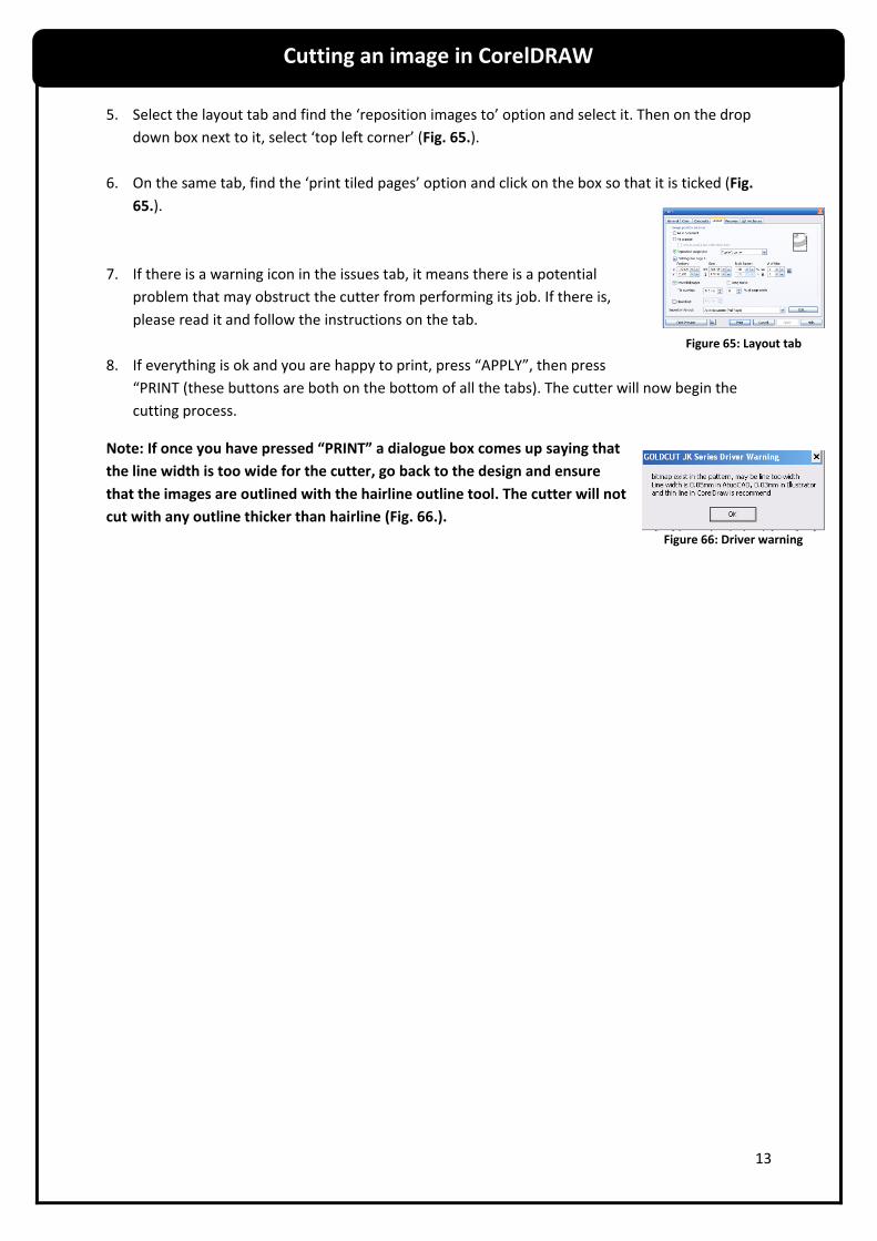
5. Select the layout tab and find the ‘reposition images to’ option and select it. Then on the drop
down box next to it, select ‘top left corner’ (Fig. 65.).
6. On the same tab, find the ‘print tiled pages’ option and click on the box so that it is ticked (Fig.
65.).
7. If there is a warning icon in the issues tab, it means there is a potential
problem that may obstruct the cutter from performing its job. If there is,
please read it and follow the instructions on the tab.
8. If everything is ok and you are happy to print, press “APPLY”, then press
“PRINT (these buttons are both on the bottom of all the tabs). The cutter will now begin the
cutting process.
Note: If once you have pressed “PRINT” a dialogue box comes up saying that
the line width is too wide for the cutter, go back to the design and ensure
that the images are outlined with the hairline outline tool. The cutter will not
cut with any outline thicker than hairline (Fig. 66.).
Cutting an image in CorelDRAW
Figure 65: Layout tab
Figure 66: Driver warning

14
Installing/ re-installing the blade
Before using the vinyl cutter or if the current blade needs replacing, a new blade will need to be
installed. It is important that it is set in the correct position to ensure a good cut. Follow these step
by step instructions to ensure the blade is correctly installed:
1. The blade assembly will be screwed into a black plastic casing. This needs to be
removed from the black casing to access the blade safely (Fig. 67.).
2. At the top of the blade assembly there is a thin metal rod that can be
depressed into the assembly to push the blade outwards. By pressing the
rod you will be able to get a safe grip of the blade so that it can be pulled
out and removed (Fig. 68. & 70.).
3. Get a new blade and find the end that tapers to a point. This end must be
inserted into the blade assembly first, so that the sharp end of the blade sticks out. The blade
will be held in place magnetically once it has been pushed in (Fig. 69.).
4. Screw the blade assembly back into the black plastic casing.
5. Find the gold ring towards the top of the blade assembly. This will limit how far the
blade can be positioned. Unscrew it until it reaches the top of the screw (just underneath the
screw head)(Fig. 70.).
6. Screw the blade assembly in so that the blade sticks out of the plastic casing by 1-2
mm. Tighten the gold ring up so that the blade is locked in place (Fig. 71.).
7. Now install the blade assembly onto the vinyl cutter motor. There should be a plastic grip
with a gold screw. Insert the blade assembly so that the top of the grip is 3-4 mm below
the lip on the black plastic casing. This is to ensure the blade does not score the
vinyl when moving between contour lines. Ensure the blade is facing in the correct
way with the shallowest angle of the blade facing towards the vinyl. Close the plastic
grip up and screw in place with the gold screw (Fig. 72.).
Vinyl cutter control settings
Before sending any Flexi 10 projects to cut, the vinyl cutter must be set correctly to
ensure a clean cut fit for the purpose of the project and the material. The vinyl cutter
control interface has settings that allow the user to determine the speed and force of
the cut and it is vitally important that these settings are correct before cutting.
The control interface contains 9 buttons and a screen that shows you the current option and the
current values that have been set. The screen will automatically show the force and speed values
when first switched on. Any adjustments can be made using the four arrows, for example, on the
force and speed settings “UP and DOWN” will control the speed and “LEFT and RIGHT” will control
the force.
Operating the Vinyl Cutter
Figure 67: Black plastic case removed
Figure 68: Removing the blade
Figure 69: Blade unit
Figure 70: Top of the blade assembly
Figure 71: How far the blade should protrude
Figure 72: Installing the blade assembly

15
The “RESET” button will restart the vinyl cutter and can also be used whilst the cutter is in action to
abort a job. The “OPTION” button allows you to move the vinyl and the blade along the x and y axis
using the arrow keys. The “SETUP” button allows you to set the “E SPEED” and “BAUD” settings by
using the arrow keys. The “MOVE” button will do a test cut on the edge of the vinyl and is useful for
testing that the force and speed values are correct. Whilst operating; holding down the “MOVE”
button pauses the cut. Press the “MOVE” button again to resume the cut. The “ORIGIN” button will
drop the blade onto the cutting surface to ensure that it has been installed correctly. If the blade is
not touching the surface then it needs positioning lower down in the plastic grip. The “ORIGIN”
button will also pause the cut whilst it is in operation by holding your finger down on the button.
Letting the button go will resume the cut.
Speed and force values
The speed and force values will vary depending on what design you need cutting, what material you
are cutting on and also the positioning of the blade on the motor. For large designs with less fine
detail the speed setting can be put up to 800 mm/s. It is recommended for smaller designs with
more fine detail that 480 mm/s is not exceeded, however you will receive a greater quality of cut in
the finer detail with a slow speed. The effect of cutting fine detail at high speed is that the vinyl may
crumple up and in some places be removed by the blade.
The force settings depend more on the material and the positioning of the blade and may need to be
tuned using the test cut (“MOVE” button). For standard vinyl and recommended blade height a force
of between 60 -80 g should be sufficient to cut the vinyl surface without cutting through the backing
as well. If the force is too light then the cutter will only score the surface, meaning that the vinyl
hasn’t been cut and will not peel away from the backing when weeding. If the force is too heavy it
will cut the vinyl and the backing and ruin the design. Note: Both the speed and force values given
are guidelines only and may vary depending on your requirements.
Installing and adjusting the vinyl
To install the vinyl simply place it in position on the rack behind the cutter in the grooves designated
for the roller to sit on. Ensure the vinyl is facing up. At the back of the cutter there are three clips
which allow the wheels to slide along the cutting surface and be adjusted. Lift the clips into an up-
right position and move the wheels until they are in the desired position. It is recommended that
they are positioned with two at the far edges of the vinyl and one in the middle to keep best control
of the vinyl. Feed the vinyl between the metal roller on the cutting surface and the wheels and check
against the ruler on the front of the cutting surface that the vinyl is straight and aligned correctly.
Clip the wheels back in place ensuring that the clips are not in a horizontal position. The vinyl will
require free movement whilst operating so ensure that there are no obstructions that could block
the movement and cause faults with the designs and tears in the vinyl. Once the design has been
cut, the vinyl can be fed through using the “OPTION” button and the Y axis arrow controls to move
the vinyl to the end of the design. This can then be sliced off using a knife so that the vinyl is ready to
be cut again.
Laser Guiding Dot
Operating the Vinyl Cutter

16
The Vinyl Cutter comes with a laser guiding dot. This is an automatic function that cannot be turned
off. The laser guiding dot helps to keep the cutter blades on the right co-ordinates so that the cut is
as accurate as possible. It is pre-set to ensure that it is always the same distance away from the co-
ordinates which ensures that the blade will follow the co-ordinate path.
Problem Reason Solution
The cutter has cut through the vinyl and the backing paper
The force is too high or the blade is protruding too far.
Reduce the force and do test cuts to ensure it is at the right depth. Ensure that the blade is sticking out 1-2mm from the black plastic casing.
The blade scores the surface of the vinyl as it moves to cut from a new point, or is returning back to the default position.
The blade is set too low, or is protruding out too far.
Ensure that the blade is sticking out 1-2mm from the black plastic casing. Then check the positioning of the blade assembly on the vinyl cutter. Make sure the lip on the black plastic casing is 3mm above the grip.
The vinyl cutter fails to cut when a project is sent.
The vinyl cutter may not be in function mode.
Ensure that the screen shows the speed and force values. If it does already, check the print options or the software.
The Vinyl ruffles up when cutting.
The speed is too fast. Reduce the speed of the cut until it is at the correct level.
The vinyl isn’t fed through the cutter head properly.
The wheels may not be clamped down properly.
Ensure all the wheels on the cutter head are clamped down properly and that none of the wheels are in the gap between the rollers.
Only half the image is cut. The printer settings may be incorrect.
Ensure that the paper size in the printer settings is set to “USER 2000 x 15240”.
The cutter flicks the vinyl up when it is cutting.
The speed is too fast. Reduce the speed until it is satisfactory.
Troubleshooting guide


![INDEX [] · chalkboard vinyl checker plate chrome/mylar concept 234 fabric wall film conspicuity tape corrugated plastic sheets coroplast cutter d, e destructable vinyl diamond plate](https://static.fdocuments.us/doc/165x107/5f05b2e87e708231d4144239/index-chalkboard-vinyl-checker-plate-chromemylar-concept-234-fabric-wall-film.jpg)


