
MANUAL - Centrifugal Pumps & Pumping Solutions · ... draw attention to the action that will cause...
25
1113 Howard Avenue E-mail: [email protected] Tel: 281-479-5000 Houston, TX 77536 USA Website: www.CURFLO.com Fax: 281-479-5001 CURFLO CENTRIFUGAL MUD PUMP XL SERIES Installation, Operation and Maintenance Instructions MANUAL
Transcript of MANUAL - Centrifugal Pumps & Pumping Solutions · ... draw attention to the action that will cause...
1113 Howard Avenue E-mail: [email protected] Tel: 281-479-5000 Houston, TX 77536 USA Website: www.CURFLO.com Fax: 281-479-5001
CURFLO CENTRIFUGAL MUD PUMP XL SERIES Installation, Operation and Maintenance Instructions
MANUAL
1113 Howard Avenue E-mail: [email protected] Tel: 281-479-5000 Houston, TX 77536 USA Website: www.CURFLO.com Fax: 281-479-5001
Foreword This manual contains instructions for the installation, operation, and maintenance of the Centrifugal Mud Pump XL-Series. As pump service conditions and specifications vary considerably in pump installation, this manual cannot cover every situation, but it is intended that the information included will serve as a guide. Should any questions arise, or start-up problems occur, it is that you contact CURFLO, Inc.
! CAUTION ! CAUTION ! CAUTION ! EXERCISE SAFETY IN ALL PERFORMANCE: DO NOT IGNORE ANY WARNING, USE ONLY APPROVED METHODS, MATERIALS AND TOOL. DO NOT PERMIT ANY FUNCTION OF QUESTIONABLE SAFETY; ACCIDENTS ARE CAUSED BY UNSAFE ACTS AND UNSAFE CONDITIONS.
! WARNING ! WARNING ! WARNING ! BEFORE PERFORMING ANY SERVICE FUNCTION, BE CERTAIN THAT THE UNIT IS SEPARATED FROM ITS POWER SOURCE OR THAT THE POWER SOURCE IS LOCKED-OUT TO PREVENT ANY FORM OF ENERGY FROM ENTERING THE EQUIPMENT.
! WARNING ! WARNING ! WARNING ! FAILURE TO READ AND COMPLY WITH THESE INSTRUCTIONS WILL VOID ALL WARRANTY EXPRESSED OR WRITTEN, WILL VOID THE RESPONSIBILITY OF THE MANUFACTURER AND MAY RESULT IN BODILY HARM OR EQUIPMENT DAMAGE.
! ATTENTION ! NOTICE ! IMPORTANT ! THESE TERMS ARE USED TO DRAW ATTENTION TO THE ACTION THAT WILL CAUSE DAMAGE TO THE PUMP, COMPONENTS OR ATTACHMENTS.
! WARNING ! WARNING ! WARNING ! BEFORE SERVICING PUMPS:
1. SHUT DOWN OR DISENGAGE THE PUMP POWER SOURCE. 2. SHUT DOWN ALL PUMP ACCESSORY EQUIPMENT. 3. RELIEVE OR “BLEED OF” ALL PRESSURE FROM THE LINES PRIOR TO REMOVING PIPING.
FAILURE TO SHUT DOWN POWER AND RELIEVE THE PRESSURE FROM THE PUMP BEFORE SERVICING CAN RESULT IN SERIOUS PERSONAL INJURY AND PROPERTY DAMAGE.
-1-
1113 Howard Avenue E-mail: [email protected] Tel: 281-479-5000 Houston, TX 77536 USA Website: www.CURFLO.com Fax: 281-479-5001
TABLE OF CONTENTS
SECTION 1 Centrifugal Mud Pump Series XL Installation
1.1 Location 4 1.2 Pump Installation 4 1.3 Coupling Alignment 4 1.4 Piping 5
A. General 5 B. Suction 5 C. Discharge 5
SECTION 2 Centrifugal Mud Pump Series XL Preparation for Operation
2.1 Mechanical Seals 6 2.2 Start-Up Checklist 6
SECTION 3 Centrifugal Mud Pump Series XL Operation
3.1 Priming the Pump 7 3.2 Pump Records 7 3.3 Lubrications 7
A. Bearings (Grease) 7
SECTION 4 Centrifugal Mud Pump Series XL Maintenance
4.1 Disassembly 8 A. General 8
4.2 Assembly 10 A. Installing Inboard Bearing Lip Seals into Frame Assembly 10 B. Test Fit Bearing Housing 10 C. Installing Bearing Cover Lip Seals 11 D. Installing Outboard Bearings on Shaft 11 E. Installing Bearing Housing onto Bearings 12 F. Installing Inboard Bearings on Shaft 13 G. Installing Bearing Cover onto Shaft 13 H. Installing Shaft Assembly into Frame 14 I. Re-Position Frame Assembly 14 J. Preparation of Stuffing Box for Mechanical Seal 15 K. Installing Stuffing Box on Frame 15 L. Installing Mechanical Seal on Sleeve 15 M. Installing Sleeve and Seal on Shaft 16 N. Installing Impeller, Jam Nut and Nose 16 O. Temporary Setting of Impeller Clearance to Avoid Interference on Installation of Cover 17 P. Installing Casing 17
-2-

1113 Howard Avenue E-mail: [email protected] Tel: 281-479-5000 Houston, TX 77536 USA Website: www.CURFLO.com Fax: 281-479-5001
TABLE OF CONTENTS
Q. Installing Front Cover on Casing 17 R. Set Final Impeller Clearance 18 S. Installing Secondary Packing for Mechanical Seals 18
4.3 Inspection
A. Impeller 19 B. Shaft 19 C. Shaft Sleeve 19 D. Mechanical Seal 19 E. Ball Bearings 19 F. Seals 19 G. General 20
4.4 Spare Parts 20 4.5 Tool Requirements 20
SECTION 5 Centrifugal Mud Pump Series XL Trouble Shooting Procedures
5.1 Excessive Packing Leakage & Rapid Packing Wear out; Shaft Sleeve Coating Worn 21
5.2 Packing Burned 21 5.3 Excessive Stuffing Box Pressure 21 5.4 Trouble Shooting Guide 22
SECTION 6 Centrifugal Mud Pump Series XL Drawings
6.1 Dimensional Outline Drawing 23 6.2 Sectional Drawing 24
-3-
1113 Howard Avenue E-mail: [email protected] Tel: 281-479-5000 Houston, TX 77536 USA Website: www.CURFLO.com Fax: 281-479-5001
SECTION 1
Centrifugal Mud Pump Series XL Installation 1.1 Location
The pump should be located near the liquid source so that the suction line may be short and direct. The pump
should be located below the level of the liquid to eliminate the necessity of priming.
1.2 Pump Installation
The installation of the pump assembly to the structure is straight forward. Lifting procedures have to be followed with safety first. Once the pump assembly is on the structure it has to be level before it can be permanently mounted to the structure.
Leveling the pump assembly can be done by using shims or wedges and a level. Once the pump is level install the bolts. Cross torque the bolts until tight.
1.3 Coupling Alignment
Good service life of the pump and driver depends upon good alignment through the flexible coupling. If the electric motor was mounted at the factory, the pump and motor were in alignment when shipped. The alignment between the pump and driver should be inspected after installation to ensure that the transportation or other handling has not caused misalignment of the unit. Poor alignment may cause vibration and failure of the coupling, pump, motor or bearings.
Alignment must not be attempted until the base is in position and the mounting flange bolts have been tighten.
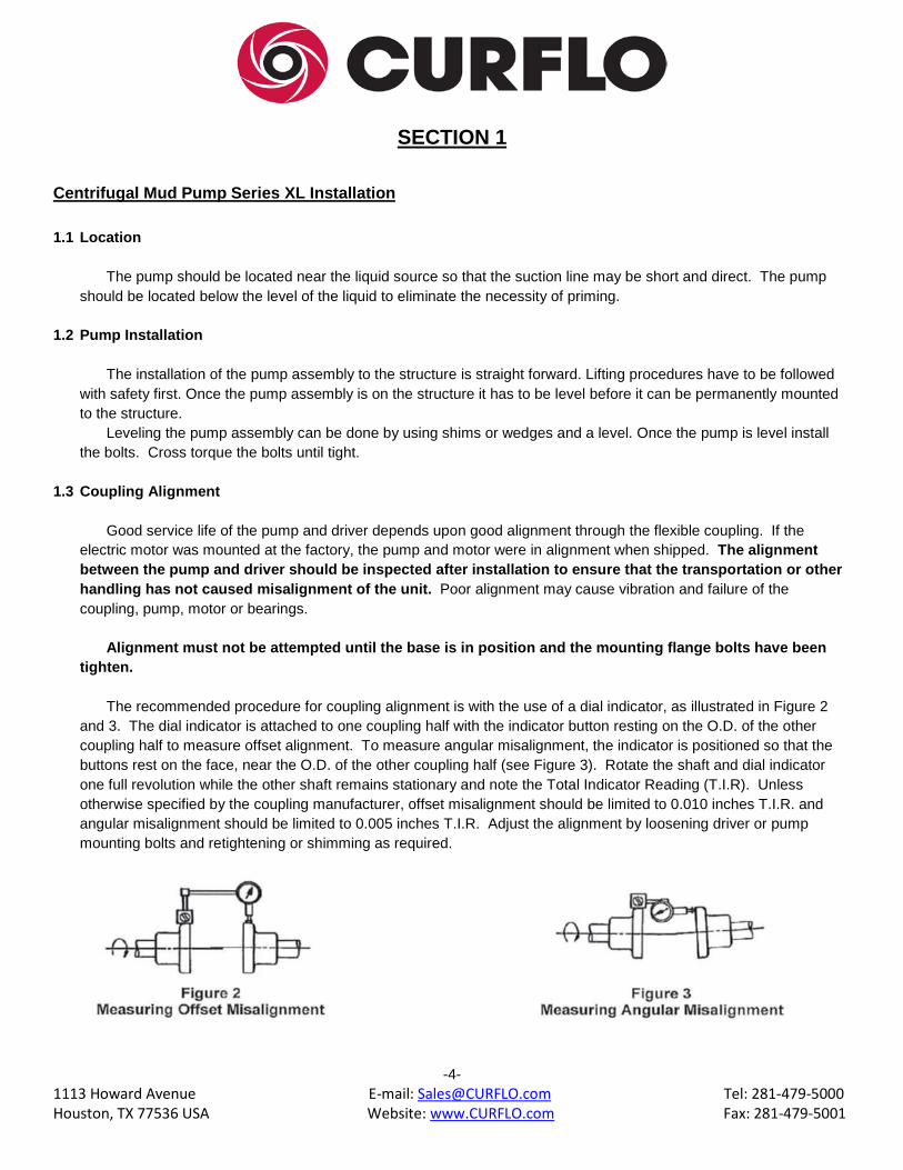
The recommended procedure for coupling alignment is with the use of a dial indicator, as illustrated in Figure 2
and 3. The dial indicator is attached to one coupling half with the indicator button resting on the O.D. of the other coupling half to measure offset alignment. To measure angular misalignment, the indicator is positioned so that the buttons rest on the face, near the O.D. of the other coupling half (see Figure 3). Rotate the shaft and dial indicator one full revolution while the other shaft remains stationary and note the Total Indicator Reading (T.I.R). Unless otherwise specified by the coupling manufacturer, offset misalignment should be limited to 0.010 inches T.I.R. and angular misalignment should be limited to 0.005 inches T.I.R. Adjust the alignment by loosening driver or pump mounting bolts and retightening or shimming as required.
-4-
1113 Howard Avenue E-mail: [email protected] Tel: 281-479-5000 Houston, TX 77536 USA Website: www.CURFLO.com Fax: 281-479-5001
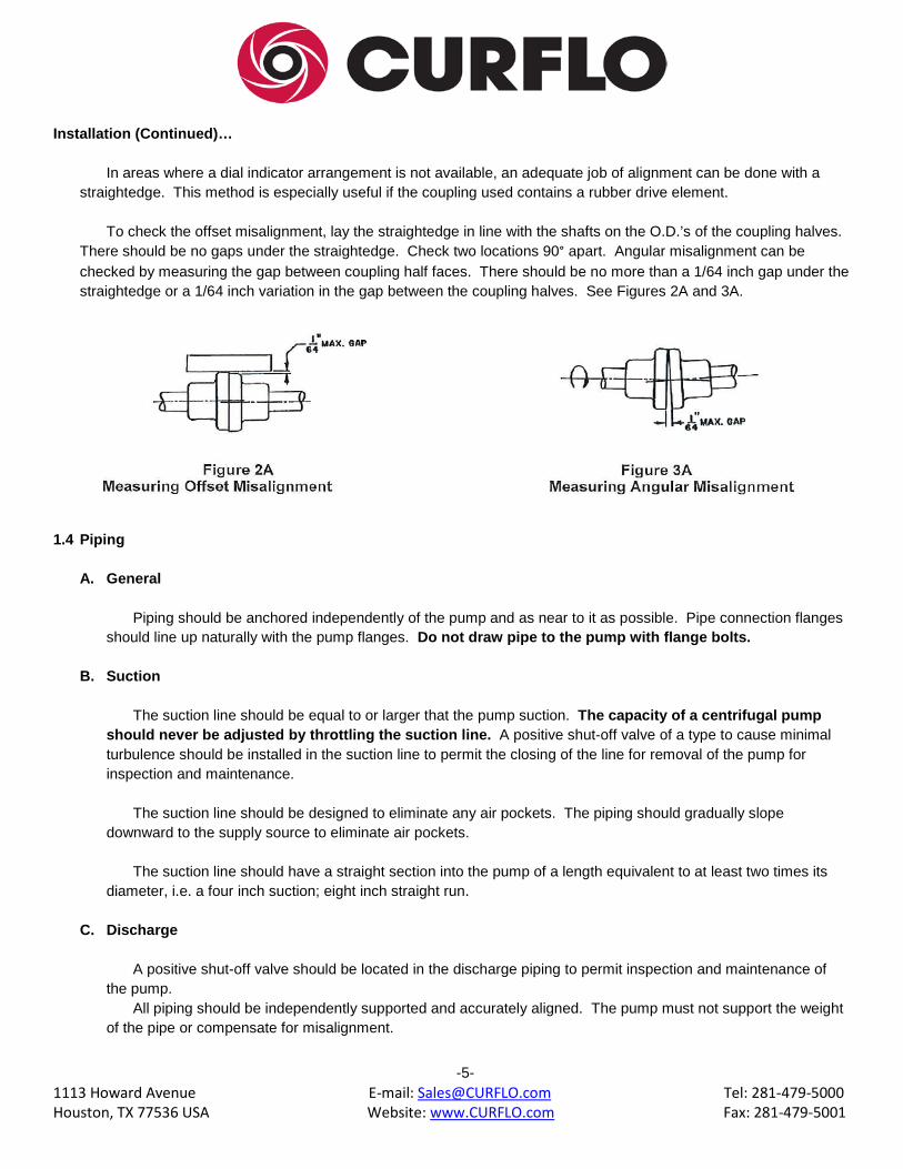
Installation (Continued)…
In areas where a dial indicator arrangement is not available, an adequate job of alignment can be done with a straightedge. This method is especially useful if the coupling used contains a rubber drive element.
To check the offset misalignment, lay the straightedge in line with the shafts on the O.D.’s of the coupling halves. There should be no gaps under the straightedge. Check two locations 90° apart. Angular misalignment can be checked by measuring the gap between coupling half faces. There should be no more than a 1/64 inch gap under the straightedge or a 1/64 inch variation in the gap between the coupling halves. See Figures 2A and 3A.
1.4 Piping A. General
Piping should be anchored independently of the pump and as near to it as possible. Pipe connection flanges should line up naturally with the pump flanges. Do not draw pipe to the pump with flange bolts.
B. Suction
The suction line should be equal to or larger that the pump suction. The capacity of a centrifugal pump
should never be adjusted by throttling the suction line. A positive shut-off valve of a type to cause minimal turbulence should be installed in the suction line to permit the closing of the line for removal of the pump for inspection and maintenance.
The suction line should be designed to eliminate any air pockets. The piping should gradually slope
downward to the supply source to eliminate air pockets. The suction line should have a straight section into the pump of a length equivalent to at least two times its
diameter, i.e. a four inch suction; eight inch straight run.
C. Discharge
A positive shut-off valve should be located in the discharge piping to permit inspection and maintenance of the pump.
All piping should be independently supported and accurately aligned. The pump must not support the weight of the pipe or compensate for misalignment.
-5-

1113 Howard Avenue E-mail: [email protected] Tel: 281-479-5000 Houston, TX 77536 USA Website: www.CURFLO.com Fax: 281-479-5001
SECTION 2
Centrifugal Mud Pump Series XL Preparation for Operation
2.1 Mechanical Seals
The seals are installed and adjusted at the factory. To properly prepare the seal for operation, various cooling and flushing flows may have to be connected. Liquid from an outside source may be required. Connect the necessary cooling and flushing flows to seal and be sure it is turned on before starting the pump.
! WARNING ! WARNING ! WARNING ! NEVER OPERATE A PUMP “DRY” WITH MECHANICAL SEALS. MECHANICAL SEAL FAILURE WILL OCCURE!
2.2 Start-Up Checklist
! WARNING ! WARNING ! WARNING ! IT IS ABSOLUTELY ESSENTIAL THAT THE ROTATION OF THE MOTOR BE CHECKED BEFORE CONNECTING THE SHAFT COUPLING. INCORRECT ROTATION OF THE PUMP FOR EVEN A SHORT TIME WILL DISLODGE THE IMPELLER AND DAMAGE THE IMPELLER, SHAFT OR BEARING HOUSING. THE PUMP SHAFT MUST TURN CLOCKWISE WHEN VIEWED FROM THE MOTOR END.
Check the following items before starting pump: A. Pump rotates freely by hand. B. Coupling aligned. C. Suction valve fully open. D. Pump and suction line full of fluid. E. Water to stuffing box or gland flush, if required. F. Discharge valve is slightly open, not fully open. Fully open the discharge valve after pump is running.
-6-
1113 Howard Avenue E-mail: [email protected] Tel: 281-479-5000 Houston, TX 77536 USA Website: www.CURFLO.com Fax: 281-479-5001
SECTION 3
Centrifugal Mud Pump Series XL Operation 3.1 Priming the Pump
Vent air from the suction line and fill it with liquid. Start the pump with the discharge valve cracked open. After discharge pressure stabilizes, gradually open the discharge valve to the required position. If flow is lost, close the discharge valve and wait a few seconds for the discharge pressure to build. Continued flow difficultly indicates improper selection or installation.
Running the pump too long with improper prime may destroy the sealing faces of the mechanical seal due to mechanical damage from heat and interface between stationary and rotating components. Do not run the pump with the suction or discharge valves closed AT ANY TIME! Thermal shock may crack the ceramic stationary seat if the temperature is raised from room temperature to 250°F in less than 30 seconds.
3.2 Pump Records
Maintain pump records whenever possible. This will provide ready access to information for ordering spare parts and for evaluating pump and mechanical seal performance. Information to be included in records should be: 1. Pump size and serial number. 2. Pump Model Number, impeller diameter, material of construction. 3. Mechanical seal type, material, manufacturer, code and drawing number. 4. Motor horsepower and speed of operation. 5. Service conditions. 6. Frequency of operation. 7. Record of maintenance, including parts usage and general pump conditions. 8. Nomenclature and part number of replacement items.
3.3 Lubrication
A. Bearings (Grease)
Bearings are pre-lubricated from the factory but should be re-lubricated with SKF grease, (LGHP2) or equivalent during pump assembly. Regular intervals of greasing will maximize the bearing life.
Five shots of grease, with a standard size hand operated grease gun, in each bearing once a week, will be
sufficient in a twenty four hour per day operation. Reduce for lesser operation. Example: Five shots every three weeks for eight hour a day operation. If longer cycle is desired, twenty shots of grease while rotating the shaft may be applied once a month, assuming twenty four hours per day operation. SKF grease, (LGHP2) would be the best choice since mixing greases sometimes causes incompatibility problems.
-7-
1113 Howard Avenue E-mail: [email protected] Tel: 281-479-5000 Houston, TX 77536 USA Website: www.CURFLO.com Fax: 281-479-5001
SECTION 4 Centrifugal Mud Pump Series XL Maintenance
4.1 Disassembly
NOTE: Refer to Sectional Drawing on page 24. A. General
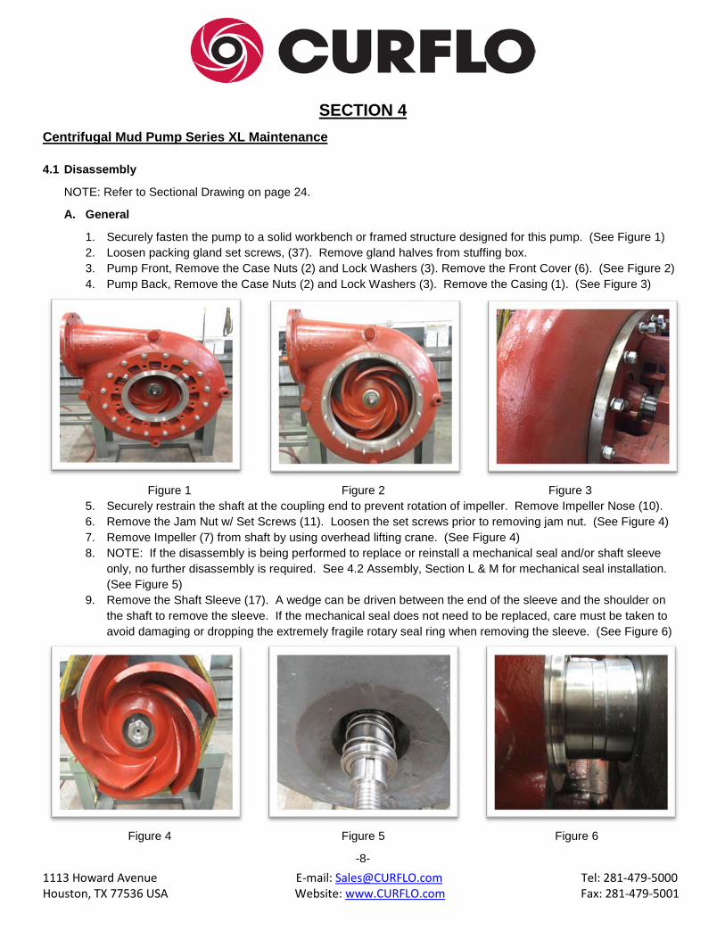
1. Securely fasten the pump to a solid workbench or framed structure designed for this pump. (See Figure 1) 2. Loosen packing gland set screws, (37). Remove gland halves from stuffing box. 3. Pump Front, Remove the Case Nuts (2) and Lock Washers (3). Remove the Front Cover (6). (See Figure 2) 4. Pump Back, Remove the Case Nuts (2) and Lock Washers (3). Remove the Casing (1). (See Figure 3)
Figure 1 Figure 2 Figure 3
5. Securely restrain the shaft at the coupling end to prevent rotation of impeller. Remove Impeller Nose (10). 6. Remove the Jam Nut w/ Set Screws (11). Loosen the set screws prior to removing jam nut. (See Figure 4) 7. Remove Impeller (7) from shaft by using overhead lifting crane. (See Figure 4) 8. NOTE: If the disassembly is being performed to replace or reinstall a mechanical seal and/or shaft sleeve
only, no further disassembly is required. See 4.2 Assembly, Section L & M for mechanical seal installation. (See Figure 5)
9. Remove the Shaft Sleeve (17). A wedge can be driven between the end of the sleeve and the shoulder on the shaft to remove the sleeve. If the mechanical seal does not need to be replaced, care must be taken to avoid damaging or dropping the extremely fragile rotary seal ring when removing the sleeve. (See Figure 6)
Figure 4 Figure 5 Figure 6
-8-
1113 Howard Avenue E-mail: [email protected] Tel: 281-479-5000 Houston, TX 77536 USA Website: www.CURFLO.com Fax: 281-479-5001
Disassembly (Continued)…
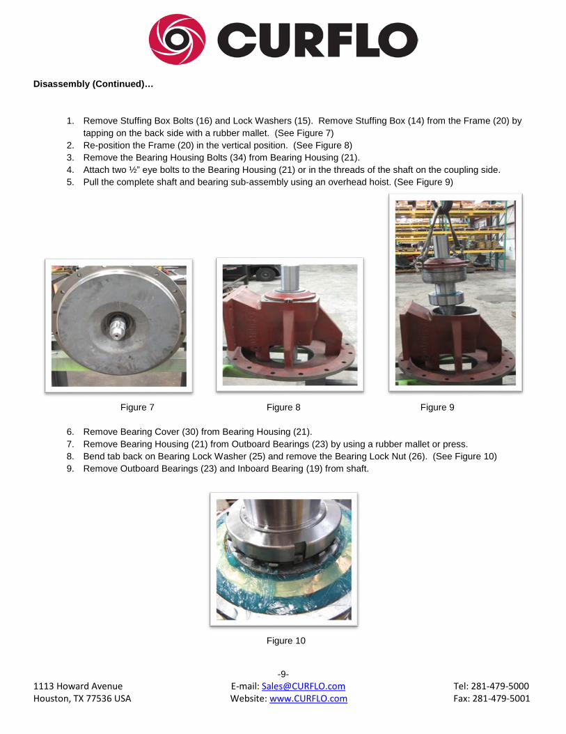
1. Remove Stuffing Box Bolts (16) and Lock Washers (15). Remove Stuffing Box (14) from the Frame (20) by tapping on the back side with a rubber mallet. (See Figure 7)
2. Re-position the Frame (20) in the vertical position. (See Figure 8) 3. Remove the Bearing Housing Bolts (34) from Bearing Housing (21). 4. Attach two ½” eye bolts to the Bearing Housing (21) or in the threads of the shaft on the coupling side. 5. Pull the complete shaft and bearing sub-assembly using an overhead hoist. (See Figure 9)
Figure 7 Figure 8 Figure 9
6. Remove Bearing Cover (30) from Bearing Housing (21). 7. Remove Bearing Housing (21) from Outboard Bearings (23) by using a rubber mallet or press. 8. Bend tab back on Bearing Lock Washer (25) and remove the Bearing Lock Nut (26). (See Figure 10) 9. Remove Outboard Bearings (23) and Inboard Bearing (19) from shaft.
Figure 10
-9-
1113 Howard Avenue E-mail: [email protected] Tel: 281-479-5000 Houston, TX 77536 USA Website: www.CURFLO.com Fax: 281-479-5001
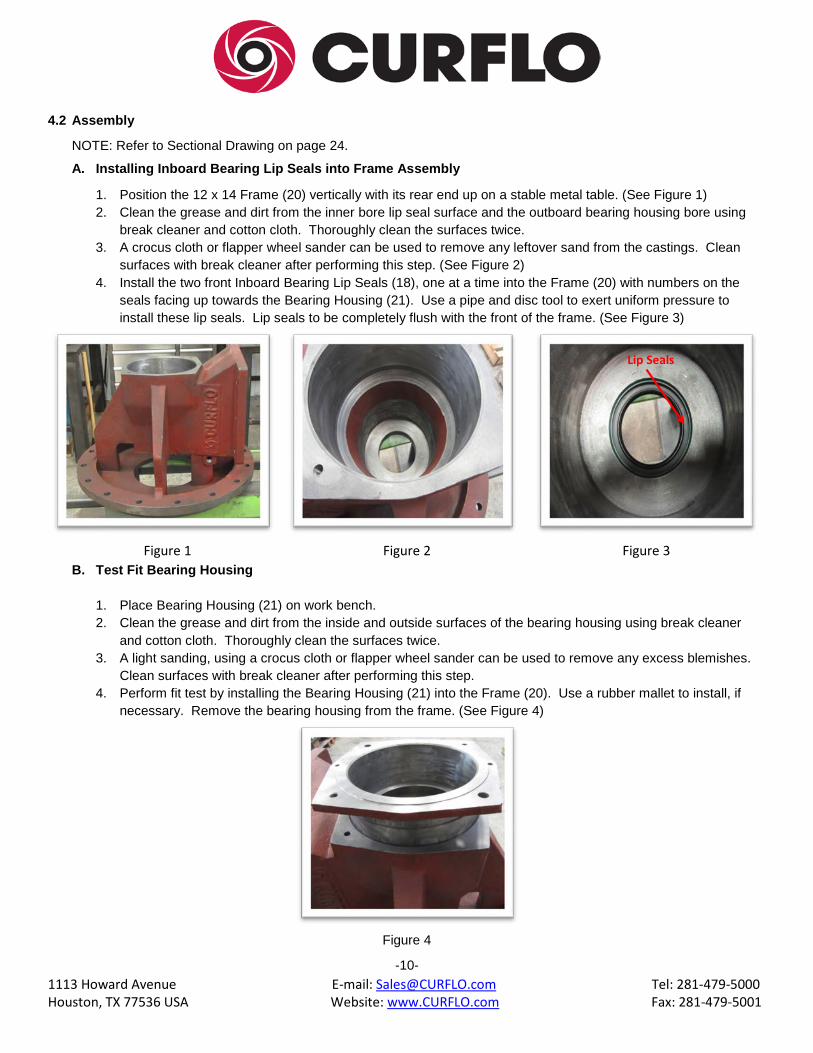
4.2 Assembly NOTE: Refer to Sectional Drawing on page 24. A. Installing Inboard Bearing Lip Seals into Frame Assembly
1. Position the 12 x 14 Frame (20) vertically with its rear end up on a stable metal table. (See Figure 1) 2. Clean the grease and dirt from the inner bore lip seal surface and the outboard bearing housing bore using
break cleaner and cotton cloth. Thoroughly clean the surfaces twice. 3. A crocus cloth or flapper wheel sander can be used to remove any leftover sand from the castings. Clean
surfaces with break cleaner after performing this step. (See Figure 2) 4. Install the two front Inboard Bearing Lip Seals (18), one at a time into the Frame (20) with numbers on the
seals facing up towards the Bearing Housing (21). Use a pipe and disc tool to exert uniform pressure to install these lip seals. Lip seals to be completely flush with the front of the frame. (See Figure 3)
Figure 1 Figure 2 Figure 3
B. Test Fit Bearing Housing
1. Place Bearing Housing (21) on work bench. 2. Clean the grease and dirt from the inside and outside surfaces of the bearing housing using break cleaner
and cotton cloth. Thoroughly clean the surfaces twice. 3. A light sanding, using a crocus cloth or flapper wheel sander can be used to remove any excess blemishes.
Clean surfaces with break cleaner after performing this step. 4. Perform fit test by installing the Bearing Housing (21) into the Frame (20). Use a rubber mallet to install, if
necessary. Remove the bearing housing from the frame. (See Figure 4)
Figure 4
-10-
Lip Seals
1113 Howard Avenue E-mail: [email protected] Tel: 281-479-5000 Houston, TX 77536 USA Website: www.CURFLO.com Fax: 281-479-5001
Assembly (Continued)…
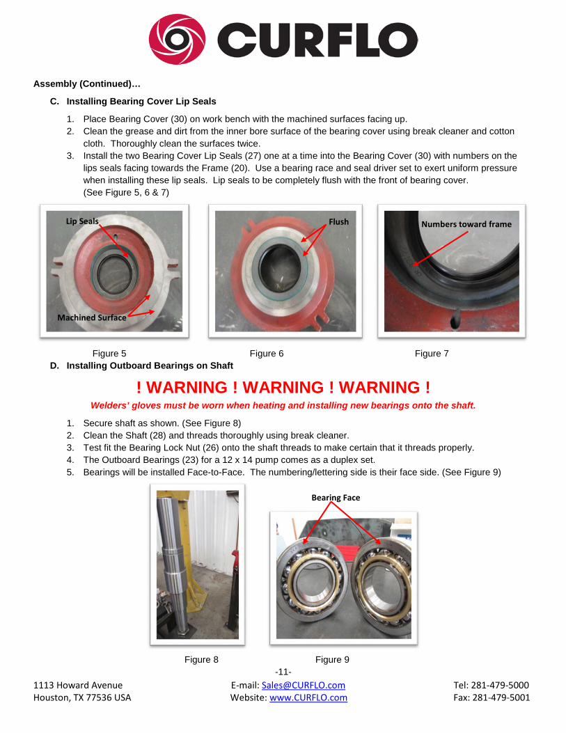
C. Installing Bearing Cover Lip Seals
1. Place Bearing Cover (30) on work bench with the machined surfaces facing up. 2. Clean the grease and dirt from the inner bore surface of the bearing cover using break cleaner and cotton
cloth. Thoroughly clean the surfaces twice. 3. Install the two Bearing Cover Lip Seals (27) one at a time into the Bearing Cover (30) with numbers on the
lips seals facing towards the Frame (20). Use a bearing race and seal driver set to exert uniform pressure when installing these lip seals. Lip seals to be completely flush with the front of bearing cover. (See Figure 5, 6 & 7)
Figure 5 Figure 6 Figure 7
D. Installing Outboard Bearings on Shaft
! WARNING ! WARNING ! WARNING ! Welders’ gloves must be worn when heating and installing new bearings onto the shaft.
1. Secure shaft as shown. (See Figure 8) 2. Clean the Shaft (28) and threads thoroughly using break cleaner. 3. Test fit the Bearing Lock Nut (26) onto the shaft threads to make certain that it threads properly. 4. The Outboard Bearings (23) for a 12 x 14 pump comes as a duplex set. 5. Bearings will be installed Face-to-Face. The numbering/lettering side is their face side. (See Figure 9)
Figure 8 Figure 9
-11-
Flush Numbers toward frame Lip Seals
Machined Surface
Bearing Face

1113 Howard Avenue E-mail: [email protected] Tel: 281-479-5000 Houston, TX 77536 USA Website: www.CURFLO.com Fax: 281-479-5001
Assembly (Continued)…
6. Heat the outboard bearings to 260°F using a bearing heater. Heating temperature should not exceed 260°F. 7. Install the first bearing with the lettering facing up. Let the bearings cool to room temperature before applying
the SKF grease, LGHP2 to both sides. (See Figure 10) 8. Install the second bearing with the lettering facing down towards the lettering on the first bearing. Allow
bearing to cool and apply SKF grease, LGHP2 to the back side of the bearing. (See Figure 11) 9. Install Bearing Lock Washer (25) with beveled side down and Bearing Lock Nut (26) onto shaft threads while
bearing are still hot in order to seal the bearings tight together. Seat the lock washer by bending the tab into the groove of the lock nut. (See Figure 12)
Figure 10 Figure 11 Figure 12
E. Installing Bearing Housing onto Bearings
1. NOTE: Let the bearing completely cool to room temperature before installing bearing housing. 2. Apply lithium grease on the inside of the Bearing Housing and to the Bearings. 3. Install Bearing Housing (21) from impeller end onto the outboard bearings until it shoulders. (See Figure 13) 4. Install Bearing Housing O-ring Seal (22) on bearing housing.
Figure 13
-12-
Lettering Direction

1113 Howard Avenue E-mail: [email protected] Tel: 281-479-5000 Houston, TX 77536 USA Website: www.CURFLO.com Fax: 281-479-5001
Assembly (Continued)…
F. Installing Inboard Bearings on Shaft
! WARNING ! WARNING ! WARNING ! Welders’ gloves must be worn when heating and installing new bearings onto the shaft.
1. Heat the Inboard Bearings (19) to 260°F using a bearing heater. Temperature should not exceed 260°F. 2. Install the Inboard Bearing (19) with the lettering facing up towards the impeller side. Let the bearing cool to
room temperature before applying the SKF grease, LGHP2 to both sides. (See Figure 14)
Figure 14
G. Installing Bearing Cover onto Shaft
1. Apply a light film of Lithium or SKF grease, LGHP2 to the bearing cover lip seals. 2. Install Bearing Cover O-ring Seal (24). 3. Install the 1/4” Grease Fitting (41). 4. Slip the entire Bearing Cover (30), over the shaft, being careful not to damage the seals over the sharp edges
of the keyway. Position the grease fitting facing up. (See Figure 15) 5. Install Bearing Cover Washers (32) and Bearing Cover Bolts (31) and tighten the cover securely against the
bearings.
Figure 15
-13-
1113 Howard Avenue E-mail: [email protected] Tel: 281-479-5000 Houston, TX 77536 USA Website: www.CURFLO.com Fax: 281-479-5001
Assembly (Continued)…
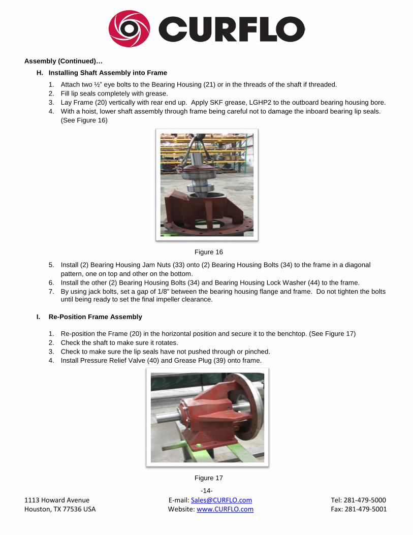
H. Installing Shaft Assembly into Frame
1. Attach two ½” eye bolts to the Bearing Housing (21) or in the threads of the shaft if threaded. 2. Fill lip seals completely with grease. 3. Lay Frame (20) vertically with rear end up. Apply SKF grease, LGHP2 to the outboard bearing housing bore. 4. With a hoist, lower shaft assembly through frame being careful not to damage the inboard bearing lip seals.
(See Figure 16)
Figure 16
5. Install (2) Bearing Housing Jam Nuts (33) onto (2) Bearing Housing Bolts (34) to the frame in a diagonal
pattern, one on top and other on the bottom. 6. Install the other (2) Bearing Housing Bolts (34) and Bearing Housing Lock Washer (44) to the frame. 7. By using jack bolts, set a gap of 1/8” between the bearing housing flange and frame. Do not tighten the bolts
until being ready to set the final impeller clearance.
I. Re-Position Frame Assembly
1. Re-position the Frame (20) in the horizontal position and secure it to the benchtop. (See Figure 17) 2. Check the shaft to make sure it rotates. 3. Check to make sure the lip seals have not pushed through or pinched. 4. Install Pressure Relief Valve (40) and Grease Plug (39) onto frame.
Figure 17
-14-

1113 Howard Avenue E-mail: [email protected] Tel: 281-479-5000 Houston, TX 77536 USA Website: www.CURFLO.com Fax: 281-479-5001
Assembly (Continued)…
J. Preparation of Stuffing Box for Mechanical Seal
1. Place Stuffing Box (14) onto work bench. 2. Clean the grease and dirt from the inside surfaces of the stuffing box using break cleaner and cotton cloth.
Thoroughly clean the surfaces twice. 3. Install Pipe Plugs (42) using pipe thread sealant into the stuffing box. 4. Turn over stuffing box and install the Stationary Seal which comes with the Mechanical Seal (13). Using
fingers firmly press the stationary seal with notched facing down into the stuffing box. (See Figure 18) 5. Clean the grease and dirt from the Shaft Sleeve (17) using memory cloth, 240 or finer and break cleaner. 6. Check fit the Shaft Sleeve (17) onto the shaft. Remove sleeve from shaft. (See Figure 19)
Figure 18 Figure 19
K. Installing Stuffing Box on Frame
1. Install Stuffing Box (14) onto Frame (20) and secure with Lock Washer (15) and Bolt (16).
L. Installing Mechanical Seal on Sleeve
1. Apply lithium grease to the O.D. of the Shaft Sleeve (17) as shown. (Figure 20). 2. Install back ring and spring. 3. Install rubber bellows on sleeve.
Figure 20
-15-
Stationary Seal Shaft Sleeve
1113 Howard Avenue E-mail: [email protected] Tel: 281-479-5000 Houston, TX 77536 USA Website: www.CURFLO.com Fax: 281-479-5001
Assembly (Continued)…
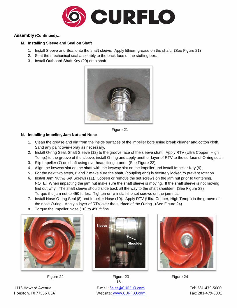
M. Installing Sleeve and Seal on Shaft
1. Install Sleeve and Seal onto the shaft sleeve. Apply lithium grease on the shaft. (See Figure 21) 2. Seat the mechanical seal assembly to the back face of the stuffing box. 3. Install Outboard Shaft Key (29) onto shaft.
Figure 21
N. Installing Impeller, Jam Nut and Nose
1. Clean the grease and dirt from the inside surfaces of the impeller bore using break cleaner and cotton cloth. Sand any paint over-spray as necessary.
2. Install O-ring Seal, Shaft Sleeve (12) to the groove face of the sleeve shaft. Apply RTV (Ultra Copper, High Temp.) to the groove of the sleeve, install O-ring and apply another layer of RTV to the surface of O-ring seal.
3. Slip Impeller (7) on shaft using overhead lifting crane. (See Figure 22) 4. Align the keyway slot on the shaft with the keyway slot on the impeller and install Impeller Key (9). 5. For the next two steps, 6 and 7 make sure the shaft, (coupling end) is securely locked to prevent rotation. 6. Install Jam Nut w/ Set Screws (11). Loosen or remove the set screws on the jam nut prior to tightening.
NOTE: When impacting the jam nut make sure the shaft sleeve is moving. If the shaft sleeve is not moving find out why. The shaft sleeve should slide back all the way to the shaft shoulder. (See Figure 23) Torque the jam nut to 450 ft.-lbs. Tighten or re-install the set screws on the jam nut.
7. Install Nose O-ring Seal (8) and Impeller Nose (10). Apply RTV (Ultra Copper, High Temp.) in the groove of the nose O-ring. Apply a layer of RTV over the surface of the O-ring. (See Figure 24)
8. Torque the Impeller Nose (10) to 450 ft./lbs.
Figure 22 Figure 23 Figure 24
-16-
Sleeve
Shoulder
1113 Howard Avenue E-mail: [email protected] Tel: 281-479-5000 Houston, TX 77536 USA Website: www.CURFLO.com Fax: 281-479-5001
Assembly (Continued)…
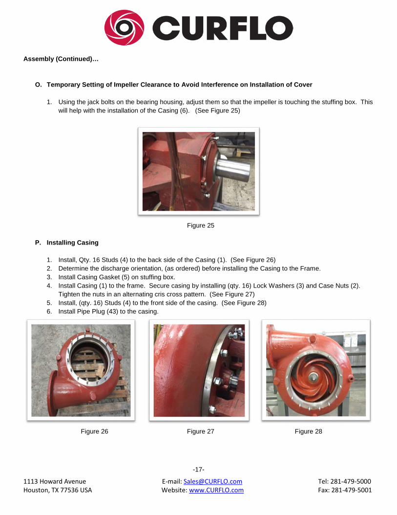
O. Temporary Setting of Impeller Clearance to Avoid Interference on Installation of Cover
1. Using the jack bolts on the bearing housing, adjust them so that the impeller is touching the stuffing box. This will help with the installation of the Casing (6). (See Figure 25)
Figure 25
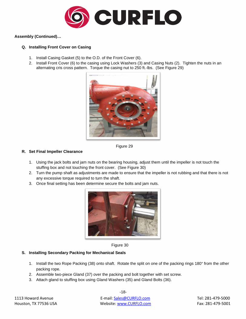
P. Installing Casing
1. Install, Qty. 16 Studs (4) to the back side of the Casing (1). (See Figure 26) 2. Determine the discharge orientation, (as ordered) before installing the Casing to the Frame. 3. Install Casing Gasket (5) on stuffing box. 4. Install Casing (1) to the frame. Secure casing by installing (qty. 16) Lock Washers (3) and Case Nuts (2).
Tighten the nuts in an alternating cris cross pattern. (See Figure 27) 5. Install, (qty. 16) Studs (4) to the front side of the casing. (See Figure 28) 6. Install Pipe Plug (43) to the casing.
Figure 26 Figure 27 Figure 28
-17-
1113 Howard Avenue E-mail: [email protected] Tel: 281-479-5000 Houston, TX 77536 USA Website: www.CURFLO.com Fax: 281-479-5001
Assembly (Continued)…
Q. Installing Front Cover on Casing
1. Install Casing Gasket (5) to the O.D. of the Front Cover (6). 2. Install Front Cover (6) to the casing using Lock Washers (3) and Casing Nuts (2). Tighten the nuts in an
alternating cris cross pattern. Torque the casing nut to 250 ft.-lbs. (See Figure 29)
Figure 29
R. Set Final Impeller Clearance
1. Using the jack bolts and jam nuts on the bearing housing, adjust them until the impeller is not touch the stuffing box and not touching the front cover. (See Figure 30)
2. Turn the pump shaft as adjustments are made to ensure that the impeller is not rubbing and that there is not any excessive torque required to turn the shaft.
3. Once final setting has been determine secure the bolts and jam nuts.
Figure 30
S. Installing Secondary Packing for Mechanical Seals
1. Install the two Rope Packing (38) onto shaft. Rotate the split on one of the packing rings 180° from the other
packing rope. 2. Assemble two-piece Gland (37) over the packing and bolt together with set screw. 3. Attach gland to stuffing box using Gland Washers (35) and Gland Bolts (36).
-18-

1113 Howard Avenue E-mail: [email protected] Tel: 281-479-5000 Houston, TX 77536 USA Website: www.CURFLO.com Fax: 281-479-5001
4.3 Inspection A. Impeller
Replace if impeller shows excessive erosion (especially on the pump-out vanes on the back of the impeller),
corrosion, extreme wear, or vane breakage.
B. Shaft
Check for runout to see that the shaft has not been bent. If runout exceeds 0.003 inch, replace the shaft.
Bearing seats and oil seal area must be smooth and free of scratches or grooves. Shaft threads must be in good condition. Replace shaft, if necessary. Proper inspection requires precision shaft rollers and proper indicating equipment.
C. Shaft Sleeve
Sleeve surface in the stuffing must be smooth and free of grooves. If grooved, replace.
D. Mechanical Seal
Seal faces, gaskets and shaft sealing members must be in perfect condition of excessive leakage may result.
Replace worn or damaged parts.
E. Ball Bearings
Replace if worn, loose, or rough and noisy when rotated. New bearings should not be unwrapped until ready for use. Replacement bearings must be of the proper size and type as supplied with the original equipment.
F. Seals
It is recommended that all O-ring seal and gasket seals removed during disassembly be replaced. In those
cases where new seals are not available, the old one can be reused if they are not torn or otherwise damaged.
G. General
All parts should be clean before assembly. This is especially important for retaining rings and O-ring seal grooves, threads, gasket surfaces and bearings lubricated areas. Any burrs should be removed with crocus cloth.
-19-
1113 Howard Avenue E-mail: [email protected] Tel: 281-479-5000 Houston, TX 77536 USA Website: www.CURFLO.com Fax: 281-479-5001
4.4 Spare Parts Recommendations • Impeller • Shaft • Stuffing Box • Shaft Sleeve • Outboard Bearing • Inboard Bearing • Inboard Labyrinth Seal • Outboard Seal • Case Gasket • Bearing Housing O-ring • Frame-to-Adapter O-ring • Mechanical Seal • Impeller O-ring • Front cover Gasket • Nose Cone • Shaft Sleeve O-ring
4.5 Tool Requirements
• Wrenches or Sockets: 7/16”, 1/2”, 9/16”, 3/4”, 7/8”, 15/16” and 1-1/8” • Screwdrivers-Flathead • Mallet-Rubber • Pliers • Allen Wrenches • Bearing Puller • Torque Wrench • Micrometer • Dial Indicators- 2 to 3 • Drift Punch-Brass • Induction Bearing Heater • Lift Slings • Feeler Gauges • Strong Workbench • Shaft Wrench • Rubber Sledge hammer • ½” Impact Gun or Ratchet • Lifting Eye • Bearing Race & Seal Driver Set • ¾ or Spindle impact Gun • 3” and 2-1/2” Socket
-20-
1113 Howard Avenue E-mail: [email protected] Tel: 281-479-5000 Houston, TX 77536 USA Website: www.CURFLO.com Fax: 281-479-5001
SECTION 5 Centrifugal Mud Pump Series XL Trouble Shooting Procedures 5.1 Excessive Packing Leakage & Rapid Packing Wear out; Shaft Sleeve Coating Worn
Remove the packing. Slide a wire with a short section of the tip bent at 90° into the stuffing box. Run the tip of the
wire along the shaft sleeve. If deep grooves are noted the sleeve must be repaired. Excessive tightening of the packing will cause rapid sleeve failure
5.2 Packing Burned
Replace the packing. Initial overtightening and attempting to run packing without leakage will cause the packing to
burn. Once the packing is burned it becomes hard and will not squeeze down on the shaft causing uncontrollable leakage.
5.3 Excessive Stuffing Box Pressure
Caused by excessive clearance between the impeller back vanes and the stuffing box cover and/or worn impeller back vanes. The solution is to readjust the impeller clearance. See the previous section entitled “Set Final Impeller Clearance” in this manual.
NOTE: Trouble shooting of mechanical seals is left to the seal manufacturer. Consult the factory if the problems
persist.
-21-
1113 Howard Avenue E-mail: [email protected] Tel: 281-479-5000 Houston, TX 77536 USA Website: www.CURFLO.com Fax: 281-479-5001
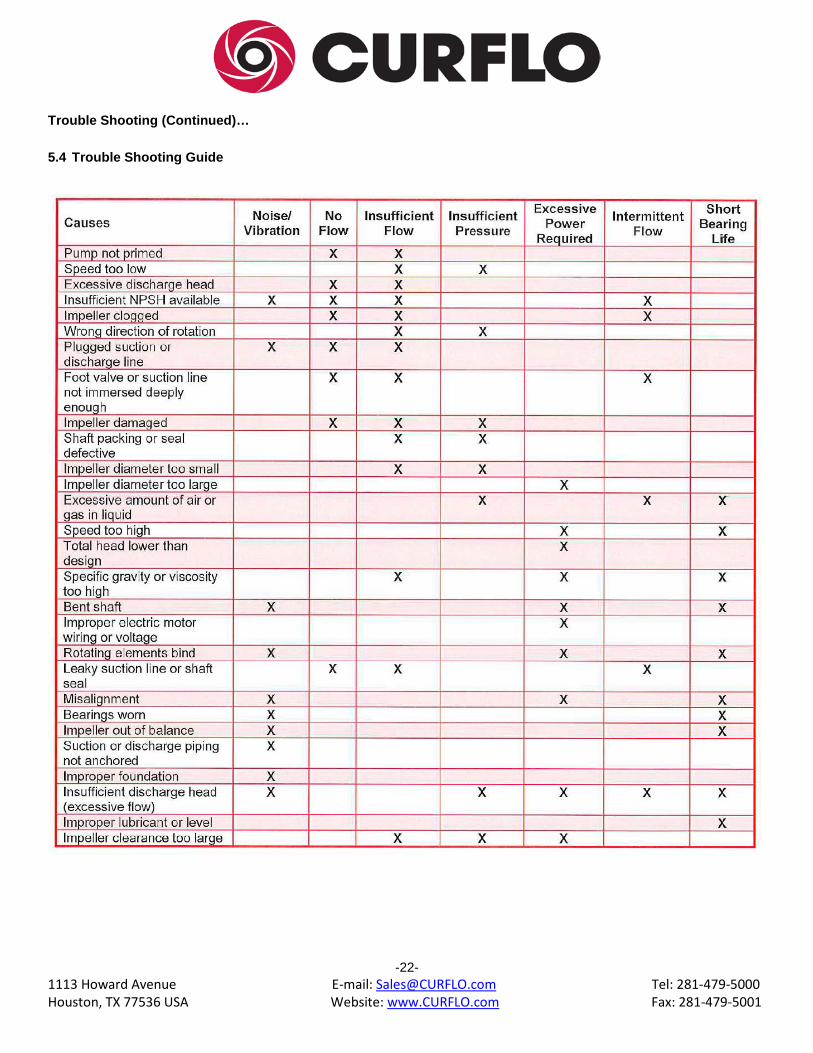
Trouble Shooting (Continued)… 5.4 Trouble Shooting Guide
-22-
1113 Howard Avenue E-mail: [email protected] Tel: 281-479-5000 Houston, TX 77536 USA Website: www.CURFLO.com Fax: 281-479-5001
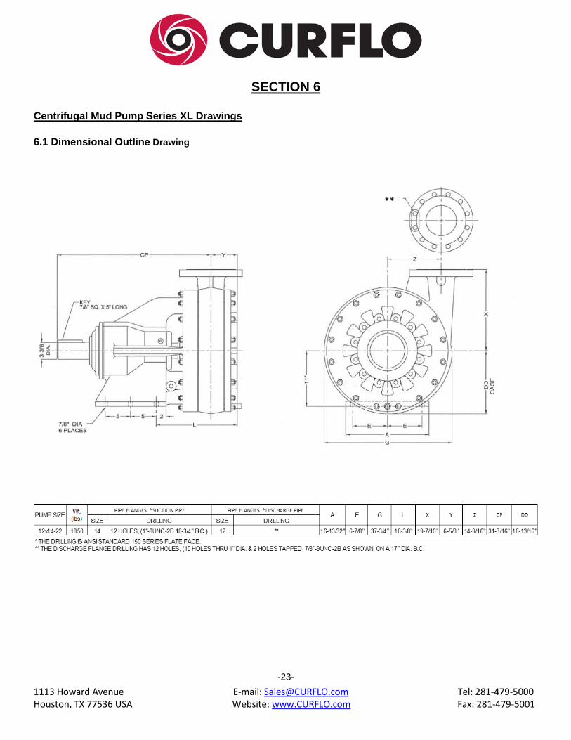
SECTION 6 Centrifugal Mud Pump Series XL Drawings 6.1 Dimensional Outline Drawing
-23-
**

1113 Howard Avenue E-mail: [email protected] Tel: 281-479-5000 Houston, TX 77536 USA Website: www.CURFLO.com Fax: 281-479-5001
6.2 Sectional Drawing
-24-
ITEM QTY ITEM QTY
1 1 23 2
2 32 24 1
3 32 25 1
4 32 26 1
5 2 27 2
6 1 28 1
7 1 29 1
8 1 30 1
9 1 31 2
10 1 32 2
11 1 33 2
12 1 34 4
13 1 35 2
14 1 36 2
15 2 37 1
16 2 38 2
17 1 39 1
18 2 40 1
19 1 41 1
20 1 42 2
21 1 43 1
22 1 44 2
XL BEARING COVER BOLT
BEARING COVER WASHER, STEEL
CF38114CS-70
CF3800FW-70
SKF OB BEARING, XL 7320 BECBM
BEARING COVER O-RING SEAL, BUNA
BEARING LOCKWASHER, W20
XL BEARING LOCKNUT, AN20
BEARING COVER LIP SEALS, 33772
12 x 14-22", XL SHAFT, STEEL
OUTBOARD SHAFT KEY
12 x 14-22", XL BEARING COVER
12 x 14-22", XL IMPELLER NOSE
CF1214112-70
CF1214026-79
CF1214027-70
CF1214028-70
CF1214029-70
CF1214032-70
CF1214010-70
CF1214034-70
12 x 14-22", XL PUMP CASE, HC
3/4" NUT, XL CASE
3/4" LOCKWASHER, CASE
3/4" B7 STUD, XL CASE
12 x 14-22", XL CASE GASKET
PART NUMBER DESCRIPTION PART NUMBER DESCRIPTION
CF1214001-55
12 x 14-22", XL FRONT COVER, HC
12 x 14-22", XL IMPELLER, CW, HC
O-RING SEAL, NOSE
IMPELLER KEY, STEEL
CF1214092-70
CF1214091-70
CF1214085
CF1214005-55
CF1214006A-55
CF1214017-79
CF12112CS-70
CF1214016-61
CF1214020-70
CF1214168-70
CF1214089-70
CF1214011
CF1214017-79
CF1214013-70
CF1214014-55
CF1214009
CF1214008-70
CF1214022-69
CF1214023-69
CF1214024-79
12 x 14-22", XL JAM NUT W/ SET SCREWS
O-RING SEAL, SHAFT SLEEVE
3.5" MECHANICAL SEAL XL, STEEL
12 x 14-22", XL STUFFING BOX, HC
1/2" LOCKWASHER, STUFF BOX
1/2" BOLT, XL STUFF BOX
12 x 14-22", XL SHAFT SLEEVE, 420S
INBOARD BEARING LIP SEALS, 36177
SKF IB BEARING, XL 5319C
12 x 14-22", XL FRAME, CI
12 x 14-22", XL BEARING HOUSING, CI
BEARING HOUSING O-RING SEAL, BUNA
CF1200LW-70
1/8" PRESSURE RELIEF VALVE, FRAME
1/4" GREASE FITTING, STEEL
1/2" PIPE PLUG, SQUARE HEAD
XL BEARING HOUSING JAM NUT
XL BEARING HOUSING BOLT
XL GLAND BOLT WASHER
XL GLAND BOLT
12 x 14-22", GLAND PACKING
1" PIPE PLUG, SQUARE HEAD
1/2" LOCKWASHER, BEARING HOUSING
CF1200HN-70
CF12112CS-70
CF3800FW-70
CF38114CS-70
CF1214015
CF1214086
CF1214044-70
CF1214093-70
CF1214090-70
CF1200PP-70
CF0100PP-70
CF1200LW-70
XL ROPE PACKING
1/8" GREASE PLUG, STEEL