Manual - Apex Instruments€¦ · Sample Line: ¼” Stainless Steel Quick -Connect or Swagelok...
63
APEX INSTRUMENTS, INC. Sorbent Trap Monitoring System Model XC-6000EM Operator’s Manual Mercury STMS
Transcript of Manual - Apex Instruments€¦ · Sample Line: ¼” Stainless Steel Quick -Connect or Swagelok...

APEX INSTRUMENTS, INC. Sorbent Trap Monitoring
System Model XC-6000EM
Operator’s Manual
Mercury
STMS

A U T O M A T E D M E R C U R Y S O U R C E S A M P L E R
Apex Instruments, Inc. | Phone: 919.557.7300 | Fax: 919.557.7110 | Web: www.apexinst.com | e-mail: [email protected]
1
S O R B E N T T R A P M O N I T O R I N G S Y S T E M XC-6000EM
Operator’s Manual
Apex Instruments, Inc. 204 Technology Park Lane Fuquay-Varina, NC 27526
Phone 919-557-7300 • Fax 919-557-7110 Web: www.apexinst.com
E-mail: [email protected]
Revised July 2015

A U T O M A T E D M E R C U R Y S O U R C E S A M P L E R
Apex Instruments, Inc. | Phone: 919.557.7300 | Fax: 919.557.7110 | Web: www.apexinst.com | e-mail: [email protected]
2
Introduction .............................................................................................................................. 3 MercSampler System...........................................................................................................................3
Features and Specs...................................................................................................................................... 5Probe............................................................................................................................................................. 6Heated Probe Connection Box ..................................................................................................................... 7
MercSampler Software .........................................................................................................................9 Installing Software .........................................................................................................................................9Driver Installation ........................................................................................................................................ 11Software Operation ..................................................................................................................................... 16Software Communication ............................................................................................................................ 17
Test Profile .........................................................................................................................................20 3.1 Alarm Actions ............................................................................................................................................. 223.2 Test Setup................................................................................................................................................... 243.3 Test Parameters: ........................................................................................................................................ 243.4 External Flow and External Moisture: ......................................................................................................... 253.5 Pre-Test Leak Check .................................................................................................................................. 263.6 Set Probe .................................................................................................................................................... 273.7 Mechanical DGM Volume Input .................................................................................................................. 283.8 Test Start .................................................................................................................................................... 283.9 Stat Screen ................................................................................................................................................. 303.10 Pause Test ................................................................................................................................................. 303.11 Adjust Screen ............................................................................................................................................. 313.12 End Test.....................................................................................................................................................323.13 Post-Test Leak Check ................................................................................................................................ 333.14 Export Data ................................................................................................................................................ 343.14 Export Data (continued)..............................................................................................................................353.15 Multi-File Export .......................................................................................................................................... 353.15 Multiple File Export (continued).................................................................................................................. 363.16 Set Clock.................................................................................................................................................... .36
Sorbent Traps.. ............................................................................................................................................... 37
Appendix 1 ..............................................................................................................................40 REPLACEMENT PARTS .........................................................................................................................40
CONSOLE ........................................................................................................................................... 40 COOLER ............................................................................................................................................. 45 PROBE ................................................................................................................................................ 46
CONSUMABLES .....................................................................................................................................47 CONSOLE ........................................................................................................................................... 48 COOLER ............................................................................................................................................. 49 PROBE ................................................................................................................................................ 50
Appendix 2 ..............................................................................................................................52 Upgrading Firmware ................................................................................................................................... 52Important Notes About Upgrading Firmware: .............................................................................................. 52Programming the STM-12B Firmware ........................................................................................................ 54After a successful upgrade:......................................................................................................................... 57
Appendix 3 ............................................................................................................................ ..58Electrical Subsystem ......................................................................................................................... .........58
Appendix 4 ............................................................................................................................ ..60XC-6000EM drawing Package .................................................................................................................. .60
Appendix 6..................................................................................................................................64 Sorbent Canister Assembly Fill Ratios.........................................................................................................64
1.0 1.1
1.2 1.3 1.4 1.52.0
2.1 2.2 2.3 2.4
3.0
4.0
Heated Umbilical .......................................................................................................................................... 7SGC-4000 Cooler.......................................................................................................................................... 8
Appendix 5................................................................................................................................63System Plumbing Diagram...........................................................................................................................63

A U T O M A T E D M E R C U R Y S O U R C E S A M P L E R
Apex Instruments, Inc. | Phone: 919.557.7300 | Fax: 919.557.7110 | Web: www.apexinst.com | e-mail: [email protected]
3
Introduction The purpose of this manual is to provide a basic understanding of the Apex Instruments automated sampling console and system components available for Sorbent Trap Monitoring. The MercSampler Model XC-6000EM console is applicable for Mercury Emissions Sampling Using Iodinated Charcoal Traps. For additional information on the applicable method, please visit http://www.epa.gov/mats/
1.0 MercSampler System Components
1.1 MercSampler ConsoleThe MercSampler Console is the operator’s control station, controlling and capturing data necessary for paired sorbent tube sampling. The basic principle of the console is to control the sample flow rate proportionally to the stack gas flow rate and to determine the standardized volume extracted through each sorbent trap. To capture the samples, a pair of diaphragm vacuum pumps work in concert with proportional valves and mass flow sensors. Optical encoders are mounted inside the gas meters to provide digital feedback for the volume sampled. From additional temperature and pressure measurements the sample volume at standard conditions (USEPA 20°C and 760mmHg) is calculated.
Model XC-6000EM MercSampler System in CR-20U AC/Heathed Cabinet with Stand

A U T O M A T E D M E R C U R Y S O U R C E S A M P L E R
Apex Instruments, Inc. | Phone: 919.557.7300 | Fax: 919.557.7110 | Web: www.apexinst.com | e-mail: [email protected]
4
The XC-6000EM Console simplifies most sampling requirements by automating data acquisition, sample flow adjustments, leak checks, calculations, termperature control and calibrations..
Data is easily transferred to a Windows-based PC through Ethernet and can be monitored remoely through modbus connectivity. The XC-6000EM MercSampler meter console captures all data necessary for paired sorbent trap sampling in accordance with EPA Method PS 12B. The meter console controls the sample flow rate proportional to the stack flow rate and determines the standardized volume extracted through each sorbent trap.
The XC-6000 firmware (embedded software) has been designed to utilize the technical features of the RISC based microchip microcontrollers which provide decision making as well as precise "autonomous" control of the console while the laptop or PC is not connected.
Model XC-6000EM MercSampler Console in Transport Case

A U T O M A T E D M E R C U R Y S O U R C E S A M P L E R
Apex Instruments, Inc. | Phone: 919.557.7300 | Fax: 919.557.7110 | Web: www.apexinst.com | e-mail: [email protected]
5
Features and Specifications of Apex Instruments Model XC-6000EM MercSampler System ComponentsFeatures XC-6000EM MercSampler System Components
Gas Meter Positive displacement diaphragm meter, 45 Lpm maximum and 0.17 Lpm starting flow rate, 0.7L/revolution
Meter Display Direct-read index or electronic totalizer with 9999.9999 cubic meter capacity, 0.2 Liter resolution (direct read) or 0.001 Liter (totalizer.) Optical encoder with quadrature pulse output to CPU increases volumetric resolution to 1 cubic centimeter or 0.001 Liters.
Dual Sample Pumps Internal KNF miniature diaphragm pump. Brushless DC (BLDC) Motor rated at 12VDC. >20inHg Maximum Vacuum. ~4Lpm maximum unrestricted flow.
Dual Proportional Valves Parker Hannifin Voltage Sensitive Orifice (VSO) Series. 47ohm, 12VDC
Dual Mass Flow Sensors SMC. Airflow Sensor, Signal Conditioning: Amplified Flow/Pressure Range: + 6000 sccm (6.0 SLPM) Linear Range 1LPM Port Style: Manifold (mass flow controller)
Barometric Sensor All Sensors 600-1000mBar, 5VDC Supply
Dual Vacuum Sensor Vacuum 0-30”Hg, 125mA
Flow Meter Dwyer 100 – 2500 ccm
Umbilical Connections Electrical: 4-pin locking Amphenol connectors
Sample Line: ¼” Stainless Steel Quick-Connect or Swagelok fittings
Dimensions 17 in x 14 in x 17 in (W x H x D)
Power Requirements 120VAC/60Hz standard 2 or more 15A circuits depending upon configuration (240VAC/50Hz optional)
Weight 110 lbs (50 kg) w/AC unit and Computer

A U T O M A T E D M E R C U R Y S O U R C E S A M P L E R
HGP Mercury Probe
HGPA Air Cooled Mercury Probe
Sorbent Trap Shields
1.2 The ProbeThere are 3 types of probes available: 2 Trap Dual Heater, Single Trap Single Heater and the Dual Trap Single Heater Air-Cooled Probes.
The heated mercury sorbent trap probes are designed to accept a pair of standard 10mm D sorbent traps. The sorbent traps are placed at the probe inlet to prevent HG trasport losses during sampling. Thraps are sealed in place with compression fittings using glass-filled PTFE ferrules.
The probes are constructed from corrosion resistant tubing. The outer sheath is 2"OD and the inner liners are 1/2" alloy. Alloy C276 is recommended for STM-12B applications.
The probe is fitted with two heaters; one to heat the traps and the second for heating the portion of the probe outside of the stack.
The heated mercury air cooled probes are for use in high stack temperature environments. These probes feature 2" stainless steel or C276 outer sheaths as a standard with indiviually controlled heat zones and integrated stack, trap and probe thermocouples.
The XC-6000EM system consists of the Probe, Connection Box, Umbilical/Heated Sample Line, Climate Control System, Cabinet and Stand
Apex Instruments, Inc. | Phone: 919.557.7300 | Fax: 919.557.7110 | Web: www.apexinst.com | e-mail: [email protected]
6

A U T O M A T E D M E R C U R Y S O U R C E S A M P L E R
Apex Instruments, Inc. | Phone: 919.557.7300 | Fax: 919.557.7110 | Web: www.apexinst.com | e-mail: [email protected]
7
1.3 Heated Probe Connection Box
1.4 Heated Umbilical Lines
The heated probe connectionbox provides a compact, positive, protective connection point for the umbilical, sampling lines, power connection and thermocouples. The umbilical heat trace neatly fits into the box to provide additional heating for the sample lines to ensure against moisture condensation. The probe sampling tubes are conveniently cleaned by removing the end caps on the sampling "T" fittings and inserting a cleaning brush into the sampling tubes.
The heated umbilical lines include the self-regulating heater cable, flexible conduit with two replaceable 1/4" PFA sample lines, pass through power and thermocouples for the probe heater. The heated core is insulated with several layers of braided lightweight Pyron OPF yarn which is burn proof and not conductive.
Ends are fitted with cam and groovefittings for easy installation and strainrelief. Passing through the fittingson the probe end are the thermocoupleconnectors, sample lines and heat traceextension with the amphenol power/signalsupply external of the fitting.
The opposite end provides the sample lines,electrical power cord, amphenol power/signal cord and male thermocouple jacks which connect to the console.

A U T O M A T E D M E R C U R Y S O U R C E S A M P L E R
Apex Instruments, Inc. | Phone: 919.557.7300 | Fax: 919.557.7110 | Web: www.apexinst.com | e-mail: [email protected]
8
1.5 SGC-4000 CoolerThe SGC-4000 Striling Gas Cooler is specially designed for removing moisture and acid gases from flue gas samples. This gas cooler uses an industiral grade super efficient Free Piston Stirling Cooler (FPSC) for chilling the gas to a constant dew point.The module is hermetically sealed in stainless steel casing to prevent corrosion and oxidation of internal parts.
The cooling system comprises of the cooler, two 12" sorbent canisters for acid and moisture removal, two coated glass condensate collection bottles and a internal temperature controller
CR-20U Cabinet with rack mounted SGC4000Portable SGC-4000 Cooler
Stirling Engine
Condensate Collection Bottles

A U T O M A T E D M E R C U R Y S O U R C E S A M P L E R
Apex Instruments, Inc. | Phone: 919.557.7300 | Fax: 919.557.7110 | Web: www.apexinst.com | e-mail: [email protected]
9
2.0 MercSampler Software The MercSampler includes firmware preloaded on its DAC and TC/MUX boards. Also included is Windows-based interface software. Apex Instruments recommends the purchase of a laptop or desktop computer directly through Apex to ensure computer compatibility and proper loading of software. However, if you prefer to use or purchase your own computer please ensure your computer has, as a minimum, the following specifications.
Item Description Capacity
CPU Processor Speed 1GHz+
RAM Random Access Memory 4MB Minimum
HDD Hard Drive Capacity ~12MB for Software. Data file storage varies.
O/S Operating System Windows XP, Vista, 7 or 8
2.1 Installing Software
To load MercSampler software on your laptop or desktop computer, follow these steps:
Insert the Apex XC-6000 MercSampler CD-ROM into your computer CD-ROM drive. Open the drive letter of the CD-ROM drive (sometimes D:\ or E:\) and execute the XC6000 Installer by double-clicking on the icon.

A U T O M A T E D M E R C U R Y S O U R C E S A M P L E R
Apex Instruments, Inc. | Phone: 919.557.7300 | Fax: 919.557.7110 | Web: www.apexinst.com | e-mail: [email protected]
10
XC-6000 Installation Wizard
Click on the Next > button to proceed with installation.
Select Installation Folder
Select the installation folder and press the Next > button to continue. The installation folder should be left at the default C:\ unless otherwise directed by Apex support personnel.
Proceed with Installation

Apex Instruments, Inc. | Phone: 919.557.7300 | Fax: 919.557.7110 | Web: www.apexinst.com | e-mail: [email protected]
11
A U T O M A T E D M E R C U R Y S O U R C E S A M P L E R
Press the Next > button to begin installation. When installation is complete, the following window will appear:
Installation Successful
The software is now installed correctly.
2.2 Driver Installation
The Apex STM-12B-TS includes a USB connection functionality, which is implemented using a virtual serial port on the connected PC. To install drivers for this serial port, please perform the following steps:
Power down the STM-12B-TS MercSampler, if it is not already powered off, by switching the main Power switch to the “OFF” position.
Connect the STM-12B-TS to the PC using the included USB cable.
Windows will discover the STM-12B-TS. The Windows “Found New Hardware Wizard” will appear onscreen.

A U T O M A T E D M E R C U R Y S O U R C E S A M P L E R
Apex Instruments, Inc. | Phone: 919.557.7300 | Fax: 919.557.7110 | Web: www.apexinst.com | e-mail: [email protected]
12
Please select “Install from a list or specific location (Advanced.)
Use the “Browse” button to find the folder where the software application is installed (usually C:\ Apex) and then navigate to the “FT232_UART_Driver” subfolder. (C:\ Apex\FT232_UART_Driver) Click “Next.”

A U T O M A T E D M E R C U R Y S O U R C E S A M P L E R
Apex Instruments, Inc. | Phone: 919.557.7300 | Fax: 919.557.7110 | Web: www.apexinst.com | e-mail: [email protected]
13
The drivers for the serial converter (UART) will be installed. Press “Finish.”
Windows will then discover the virtual serial port. The installation for the serial port drivers is the same as for the serial converter. The “Found New Hardware Wizard” will start:
Select “Install from a list or specific location (Advanced,)” and press “Next.”

A U T O M A T E D M E R C U R Y S O U R C E S A M P L E R
Apex Instruments, Inc. | Phone: 919.557.7300 | Fax: 919.557.7110 | Web: www.apexinst.com | e-mail: [email protected]
14
Select the driver location (same as for the serial converter installed previously) and press “Next.”
The wizard will complete. Press “Finish.” Open the System Properties control panel (either open Control Panel > System or right click on My Computer and select “Properties.”

A U T O M A T E D M E R C U R Y S O U R C E S A M P L E R
Apex Instruments, Inc. | Phone: 919.557.7300 | Fax: 919.557.7110 | Web: www.apexinst.com | e-mail: [email protected]
15
Click the “Hardware” tab, then click “Device Manager.”
When the Device Manager opens, open up the “Ports (COM & LPT)” item and make sure that a “USB Serial Port” is installed. Please make a note of the COM number (in this case, it is COM4, but your installation may vary.)

A U T O M A T E D M E R C U R Y S O U R C E S A M P L E R
Apex Instruments, Inc. | Phone: 919.557.7300 | Fax: 919.557.7110 | Web: www.apexinst.com | e-mail: [email protected]
16
2.3 Software Operation
Follow these steps to start the MercSampler software on a laptop or desktop computer: Double click the “XC-6000” icon on your desktop. The Initial Main Screen, as shown below, is displayed. Please take a moment to note the version number of the software. It is displayed on the right, center screen just above the task block as indicated below.
Initial Main Screen
If you have already setup the communication method, single click the “Connect” button. Skip the following section and go to the Test Profile section. Otherwise, follow the instructions to set up the communication between the console and the computer.
Version #

A U T O M A T E D M E R C U R Y S O U R C E S A M P L E R
Apex Instruments, Inc. | Phone: 919.557.7300 | Fax: 919.557.7110 | Web: www.apexinst.com | e-mail: [email protected]
17
2.4 Software Communication The MercSampler software communicates via USB or Ethernet (optionally wireless Ethernet). To connect single click the “Config/Utilities” button. The following screen will appear.
Config & Utilities Screen
To connect via USB follow these steps: 1. Select the “COM Port” button under the Connection Method.2. Single click the “Locate COM Ports”.3. Select an available COM Port – make sure that this COM number is the same as the COM
number for the USB Serial Port installed previously.4. Single Click “Return” and the Main Screen will appear.5. “End” the program and reopen the program by double-clicking the desktop icon.6. Single click the “Connect” button. The screen will indicate the console ID, communication
method and console date/time.
To connect via Ethernet follow these steps: 1. Select “TCP/IP” button under the Connection Method.2. Type in the IP address 192.168.1.2 and Port 81.3. Single Click “Return” and the Main Screen will appear.4. “End” the program and reopen the program by double-clicking the desktop icon.5. Single click the “Connect” button. The screen will indicate the console ID, communication
method and console date/time.

A U T O M A T E D M E R C U R Y S O U R C E S A M P L E R
Apex Instruments, Inc. | Phone: 919.557.7300 | Fax: 919.557.7110 | Web: www.apexinst.com | e-mail: [email protected]
18
Important note: If you experience errors in TCP/IP connection, please follow the steps below: 1. Click the Windows Start button (located in the lower left corner of the screen.)2. Click the Run… button
3. Type “notepad c:\windows\system32\drivers\etc\hosts” into the Run\Open: Window.
4. The Notepad text editor window should appear, with the Windows HOSTS file loaded.5. This file enables the user to specify a DNS entry for a static IP address, which is needed for
some system configurations.
6. Add the text highlighted above: 192.168.1.2 xc60007. Save the HOSTS file by selecting File -> Save from Notepad’s top menu.8. If you require additional assistance in configuring your TCP/IP settings, including configuringthe STM-12B console to join a plant-wide network, please contact Apex Instruments for further technical support.

A U T O M A T E D M E R C U R Y S O U R C E S A M P L E R
Apex Instruments, Inc. | Phone: 919.557.7300 | Fax: 919.557.7110 | Web: www.apexinst.com | e-mail: [email protected]
19
When connected the main screen identifies the console and the communication method as shown below:
Main Screen Communication Connected
The following summarizes the steps involved in configuring and running a complete test with the MercSampler Console.
Software Flow Summary
Main ScreenProfile Options Load from Flash Memory Load from File Load New/Default Edit Current Profile
Step 1Load/Edit ProfileProfile Includes:Test Duration,Constant vs Proportional Flow ControlTarget Flow RateTest Site InfoAlarm Configuration, Etc.Save Profile
Step 2Pre-Test Leak CheckMax Vacuum and OptionalVariable Levels of 5" Hg and 10" HgTroubleshoot/repair leaksTimeout PeriodAccept stores value
Step 3Set ProbeInsert ProbeConfirm Location and Delta P MeasurementCheck Temperature Values and Set Points
Step 4Start TestProgram prompts the Userto Enter Trap ID's and DGM Mechanical Index Readings
Step 5Real-time DataView Real-time data and Check for IrregularitiesAlarm ActionsCommunications
Step 6End TestEnter Final Reading of DGM index. Remove Probe from StackPrepare for Leak Check
Step 7Post-Test Leak CheckAutomatically Leak Checks toMax Vacuum Logged DuringSamplingOptional Higher VacuumLevels if Selected
Step 8Export FileDownload Selected Data File(s) to Selected Location,such as Jump Drive,Hard Drive, Network, etc.
Import into Spreadsheet/Database Application

A U T O M A T E D M E R C U R Y S O U R C E S A M P L E R
Apex Instruments, Inc. | Phone: 919.557.7300 | Fax: 919.557.7110 | Web: www.apexinst.com | e-mail: [email protected]
20
3.0 Test Profile The Test Profile configures the console for running a test. A profile can be loaded from the internal flash memory on the DAC board inside the console. This is done by single clicking the “From Memory” button on the Main screen
Load Profile from Internal Memory Screen
Once loaded this filename is visible in the lower left corner of the Main screen. This can be edited by single clicking the “Edit Profile” button. The first screen to appear is the General Information screen shown below. This allows the user to enter the Client’s and Opertor’s information. There are several optional screens in this profile. The user has the option to enter the data and click “Next” to cycle through or this information is optional and can be bypassed by clicking the “Test Setup” Screen.
General Test Information Screen

A U T O M A T E D M E R C U R Y S O U R C E S A M P L E R
Apex Instruments, Inc. | Phone: 919.557.7300 | Fax: 919.557.7110 | Web: www.apexinst.com | e-mail: [email protected]
21
Stack Information Screen
The Stack Information data is optional and is not used in any calculations. It is for descriptive or reporting purposes only.
Test Equipment Information Screen
The Test Equipment information is also optional. However, the Cartridge or Trap IDs are highly recommended to enter. It is optional here because the user is prompted later to enter this information.

A U T O M A T E D M E R C U R Y S O U R C E S A M P L E R
Apex Instruments, Inc. | Phone: 919.557.7300 | Fax: 919.557.7110 | Web: www.apexinst.com | e-mail: [email protected]
22
Alarm Actions Screen
3.1 Alarm Actions
The Alarm Actions screen allows the user to configure the software to trigger an alarm condition based on several available parameters. Each alarm condition has several parameters that may be set. For each sensor input on the Alarm Actions screen, a valid range or upper limit may be set, depending on the sensor type. Additionally, most alarms feature an auto-reset function, which serves to return the console to a non-alarm state in the case of a non-critical alarm condition.
DELAY (sec.) Length of time alarm condition must continue before alarm action is performed. For an instant alert, set to zero (0.)
AUTO-RESET (sec.) Length of time elapsed before alarm condition resets. When alarm
condition resets, Alarm Piezo output and dry contact will deactivate.
ALARM ACTION: Action performed by the software upon reaching an alarm condition. See table below
RETURN FROM POWER FAILURE ACTION: When the console returns from a power failure, the unit may trigger an
alarm. Any available Alarm Action may be used, including END TEST or PAUSE. If ALERT is used, the alarm may be Auto-Reset after a specified interval.
ALARM DELAY (Startup / Resume) When a test run is started or resumed from a pause condition, the alarms will be disabled for a minimum of 60 seconds, in order to prevent false alarm conditions when establishing the flow baseline. This delay may be extended at the user’s discretion.
A U T O M A T E D M E R C U R Y S O U R C E S A M P L E R
Apex Instruments, Inc. | Phone: 919.557.7300 | Fax: 919.557.7110 | Web: www.apexinst.com | e-mail: [email protected]
23
ACTION Description of Action
ALERT Console Alarm dry contact output will close Console Alarm Piezo output will engage
May be Auto-Reset or reset manually by operator
PAUSE Console Alarm dry contact output will close Console Alarm Piezo output will engage
Test will pause until manually resumed by operator May not be Auto-Reset
END TEST Console Alarm dry contact output will close Console Alarm Piezo output will engage
Test will end and unit will wait for post-leak test May not be Auto-Reset
DISABLE No action

A U T O M A T E D M E R C U R Y S O U R C E S A M P L E R
Apex Instruments, Inc. | Phone: 919.557.7300 | Fax: 919.557.7110 | Web: www.apexinst.com | e-mail: [email protected]
24
3.2 Test Setup
The Test Setup screen is the core of the Test Profile. This is where the user selects the test duration, averaging period, target flow rates, flow control method, etc. The External Pause parameters may be selected on this screen.
Test Setup Screen
3.3 Test Parameters: Duration: Length of time the test is run. Note that this is the total run time, not calendar
or clock time. If a test is paused, the unit will ignore the pause time and will continue the test until the entire duration has elapsed. Entered in Days / Hours / Minutes.
Averaging Period: Duration of block average points stored in the console internal memory. If a 15-minute averaging period is specified, the unit will average all appropriate data and write data points to storage memory every fifteen minutes. 1-minute averaging times are recommended for shorter runs. For longer runs (greater than 24 hours) longer averaging times may be used.
Trap and Probe Heaters Temperature: Set Point for the console-controlled heaters in the sample probe. This should be set high enough to keep any water vapor or other moisture entrained in the stack gas without condensing. In a “wet” stack (more than 10% moisture,) trap and probe heaters should be set to well above stack temperature.
Chiller Temperature: This parameter does not control the sample conditioner, but it does provide a reference temperature used in setting the alarm values. Typically 35° F.
External Pause: Determines whether the unit will enter a pause state when the External Pause input is activated. Disable will never pause, When contacts are shorted and When contacts are open will pause when their conditions are met. When the unit is paused, the sample pumps are turned off and the elapsed time counter is not incremented.

A U T O M A T E D M E R C U R Y S O U R C E S A M P L E R
Apex Instruments, Inc. | Phone: 919.557.7300 | Fax: 919.557.7110 | Web: www.apexinst.com | e-mail: [email protected]
25
3.4 External Flow and External Moisture: The software is designed to operate with a proportional flow input, which is used to change the target flow rate of the console. The software can accept an analog input signal (0-10V or 4-20 mA,) a ΔP signal from a pitot transducer, or a digital flow input over Modbus.
In order to use proportional flow, select an initial flow rate and an external flow signal source.
In this example, we have selected 500 cc / min. and 4-20mA for our external flow signal. The External Flow Input Scaling fields are designed to make the exported data agree with the stack flow data obtained by the plant stack flow monitor. If known, input the correct stack flow value observed when the external flow signal is a nominal zero (0V or 4mA.) Then input a known current / voltage and its corresponding stack flow rate. The Unit field is optional but will be shown in the data. If the exact stack flow is not known, the Span mA may be set to the current external signal and the Span Flow Rate may be set to the current load percentage. If this is done, the Unit field should be set to “percent load” to indicate this situation in the data.
The final field is Minutes to establish the baseline, and should be left at 1 minute unless directed otherwise.
When the software begins sampling, the console will monitor stack flow during the baseline time period and will store the average stack flow in memory. The initial flow rate will be maintained as long as the stack flow is equal to the baseline stack flow. If the stack flow increases, the console sampling flow rate will also increase proportionally.
EXAMPLE: The initial flow rate is set to 500 cc/min. The external signal is set to 4-20mA, zero = 0.0001, span 20.00 = 1000 as pictured above. The unit is set to Kscfm (thousands of standard cubic feet per minute.) When the test begins, the stack flow is 875 Kscfm. The software sets its initial flow rate of 500 cc/min to be equivalent to 875 Kscfm. Over the course of the next hour, the load of the station increases from 87.5% to 91%. The stack flow increases from 875 Kscfm to 910 Kscfm (a 4% increase,) and the software increases its sample flow rate from 500 cc/min to 520 cc/min (also a 4% increase.) In this way, the software maintains proportionality during a sample run.

A U T O M A T E D M E R C U R Y S O U R C E S A M P L E R
Apex Instruments, Inc. | Phone: 919.557.7300 | Fax: 919.557.7110 | Web: www.apexinst.com | e-mail: [email protected]
26
Click “Save” to save this to a location on your hard drive. Please note that selecting “Save” does not write any information to the memory of the console. The software profile is not updated until all pre-test preparations are complete. Click “Main Menu” to start the testing protocol.
Save Profile Screen
3.5 Pre-Test Leak Check Once back at the “Main” screen single click the “Pre-Test Leak Check” button. The following screen will appear. Ensure the sorbent test tubes are inserted in the probe trap receptacles. Plug the ends of the sorbent tubes with clean stoppers. Click the two “Start Test” buttons to individually leak check Side A and B. This is a required leak check done at maximum vacuum. The leak check vacuum level and flow rate are stored with each test run. The test can be bypassed by checking the “Bypass” button and then selecting “Next>>>”. However, this bypass will be logged and stored with the data.
Pre-Leak Test Screen Running

A U T O M A T E D M E R C U R Y S O U R C E S A M P L E R
Apex Instruments, Inc. | Phone: 919.557.7300 | Fax: 919.557.7110 | Web: www.apexinst.com | e-mail: [email protected]
27
Passed Pre-Leak Test Screen
Once the test has passed click the “Next” button. The system prompts you to switch the pumps off using the “Pump Off” button on the screen. Click next to continue. The system will automatically switch these off prior to starting the test.
Pre-Leak Test Pump Off Prompt
3.6 Set Probe The next screen to appear prompts the user to insert the probe when the temperatures are at/near set point. If the internal pitot is being used the current/live delta p reading is shown.
Set Probe Screen

A U T O M A T E D M E R C U R Y S O U R C E S A M P L E R
Apex Instruments, Inc. | Phone: 919.557.7300 | Fax: 919.557.7110 | Web: www.apexinst.com | e-mail: [email protected]
28
3.7 Test Data Storage Location The following prompts the user to select a storage location on the flash memory drive inside the box. Single click the number in the left column corresponding to where the data file is to be stored. The user can select one of up to 99 slots. Click the “<<Previous” or “Next>>” buttons to scroll through the list. The system will prompt to confirm the case of overwriting data.
Memory Slot Selection for Data Storage Screen
3.8 Mechanical DGM Volume Input The following prompts the user to enter or confirm the trap ID s and enter the initial dry gas meter mechanical readings. This is used as a redundant backup and functionality check of the metering system.
Mechanical DGM Index Screen

A U T O M A T E D M E R C U R Y S O U R C E S A M P L E R
Apex Instruments, Inc. | Phone: 919.557.7300 | Fax: 919.557.7110 | Web: www.apexinst.com | e-mail: [email protected]
29
3.9 Test Start After clicking “Accept” the following screen appears. The system is ready to start the test.
Test Ready to Run Screen
To start, click “Run” and the system should indicate flow with the digital rotameters in the top right of the screen. Also, check to ensure the electronic totalizer on the gas meter is incrementing.
Test Running Screen

A U T O M A T E D M E R C U R Y S O U R C E S A M P L E R
Apex Instruments, Inc. | Phone: 919.557.7300 | Fax: 919.557.7110 | Web: www.apexinst.com | e-mail: [email protected]
30
3.9 Stat Screen To see a non-graphical representation of the run data screen, single click the “Stat” button and the following screen will appear. This screen does override other screens and will need to be closed in order to open another screen. Close this screen by clicking the X box in the top right of the screen.
Stat / Sensors Screen
3.10 Pause Test To pause the test, single click the “Pause” button in the center of the screen. The button will then toggle to “Run” to continue the test.
Test Paused Screen

A U T O M A T E D M E R C U R Y S O U R C E S A M P L E R
Apex Instruments, Inc. | Phone: 919.557.7300 | Fax: 919.557.7110 | Web: www.apexinst.com | e-mail: [email protected]
31
In addition, a remote pause functionality has been integrated into the software. By interfacing with the remote pause connector on the rear panel of the unit, the user may pause the test without the need for a connected PC. The remote pause functionality is discussed in the Test Setup menu.
3.11 Adjust Screen The software is designed to offer flexibility during testing as well as when creating profiles. Press the Adjust button to change the trap / probe heater set point or the target flow rate during testing,
Adjust Screen
The Trap Heater Setpoint Adjust section allows either an arbitrary set point or a set point 0-99 degrees F above the stack temperature to be set. The original set point is stored and may be recalled using this screen as well.
The Adjust Flow Rate section allows the flow rate to be increased or decreased from the original target flow rate. Positive numbers between 0 and 999 add to the flow rate, while negative numbers between -1 and -998 reduce the flow target.
After changing any parameters on the Adjust Screen, press the Apply New Temperature and / or Apply New Flow Rate buttons, and then close the screen by pressing the Close button.

A U T O M A T E D M E R C U R Y S O U R C E S A M P L E R
Apex Instruments, Inc. | Phone: 919.557.7300 | Fax: 919.557.7110 | Web: www.apexinst.com | e-mail: [email protected]
32
3.12 End Test To end the test there are two options. The user can wait until the system times out and automatically stops the test. Second, the user can end the test early by single clicking the “End Test” button in the center of the graphical run data screen. The system will prompt the user to confirm this action.
End Test Early Prompt
The following prompt informs the user the system will store the data.
End Test Confirmation Prompt
The following prompt informs the user the Post-Test Leak check is next and to remove the probe from the stack and plug the ends of the traps.
Initial Post-Test Leak Check Prompt

A U T O M A T E D M E R C U R Y S O U R C E S A M P L E R
Apex Instruments, Inc. | Phone: 919.557.7300 | Fax: 919.557.7110 | Web: www.apexinst.com | e-mail: [email protected]
33
3.13 Post-Test Leak Check The following screen displays the status of the leak check and allows the user to start/pause the leak check. The system has logged the highest vacuum achieved for both flow channels A and B as displayed in the center box and will control the vacuum level to just over those levels. Just like with the Pre-Test Leak Check, the user can bypass this step but no leak check data will be stored. However, if no Post-Leak is performed the sample run data will be invalid.
Initial Post-Test Leak Test Screen
Running Post-Leak Test Screen
After both flow channels have passed. Click the “Next>>>” button and cycle off the pumps and the system will inform the user it is storing the leak check data.
Save Data to Memory Prompt

A U T O M A T E D M E R C U R Y S O U R C E S A M P L E R
Apex Instruments, Inc. | Phone: 919.557.7300 | Fax: 919.557.7110 | Web: www.apexinst.com | e-mail: [email protected]
34
3.14 Export Data The system will now go back to the main screen. To export and view the data file(s), Click on the Export Data box.
Export Data to File from main screen
Now select test data to export, the bottom right of screen will indicate sample run just completed.
Export Data from Memory Slot
Click on the button corresponding to the slot number of the test to be exported. The software supports 99 memory slots, which may be accessed 20 at a time using the Previous and Next buttons.
Export Slot 1
Next Page
Previous Page
Export Data Button

A U T O M A T E D M E R C U R Y S O U R C E S A M P L E R
Apex Instruments, Inc. | Phone: 919.557.7300 | Fax: 919.557.7110 | Web: www.apexinst.com | e-mail: [email protected]
35
3.14 Export Data (continued)
Once the slot number button is pressed, the following dialog box will prompt the user to save the file to a local or network location. A text file (.txt) and a comma separated value (.csv) file will be generated at this user-specified location. The text file can be viewed in various applications such as Notepad, Word Pad, Word, Excel, etc. The CSV file is formatted to be opened in a spreadsheet application such as Excel.
Export Data Path Screen
3.15 Multi-File Export
The software also supports multi-file export, which will export a group of completed test profiles to a folder on the local hard drive. To use multi-file export, select the Multiple Slot Export check boxes next to the slots desired. To select all available slots, press the ALL button. To clear all selected slots, press the CLR button.
Multiple slot export check boxes
Export Group
Clear All
Select All

A U T O M A T E D M E R C U R Y S O U R C E S A M P L E R
Apex Instruments, Inc. | Phone: 919.557.7300 | Fax: 919.557.7110 | Web: www.apexinst.com | e-mail: [email protected]
36
3.15 Multiple File Export (continued) After the slots are selected, press the Export Group button. The software application will prompt the user for a directory as in single file export. With a multiple file export, all slots will be exported to the directory selected for the first slot. Exported files will be named based on their profile name, and all will be given unique filenames.
3.16 Set Clock The Config/Utilities screen has various other functions built-in. The “Set Clock” button automatically synchronizes the MercSampler Console time with the clock time of the computer connected.
Set Console Clock Confirmation Screen

A U T O M A T E D M E R C U R Y S O U R C E S A M P L E R
Apex Instruments, Inc. | Phone: 919.557.7300 | Fax: 919.557.7110 | Web: www.apexinst.com | e-mail: [email protected]
37
4.0 Sorbent Traps The system is designed to capture mercury in a pair of glass tubes called sorbent traps. These traps are partially filled with activated charcoal (carbon) and are divided into two or more sections by fiberglass or glass wool insulation. The stack gas is drawn through the sorbent trap and any mercury present in the gas stream is captured by the sorbent.
The “front” section is designed to capture all of the mercury from the source.
The second section is a buffer, and is designed to capture any mercury that escapes the first section. In most testing, exceeding a certain amount of mercury in this section will invalidate test results.
The third section (if present) is the “spike” section. A known mass of mercury is deposited in this section, and acts as a control to ensure that the first two sections are working properly. When the contents of the third section are analyzed after the sample collection, the results should show the mass of mercury to be the same both before and after sample collection on this section. In most testing, failure to recover the spike will invalidate test results.
For RATA testing, baseline testing, and engineering studies, two-section traps are generally used. Consult with your local environmental regulatory body to determine the trap types required for your application.
Three-Section Sorbent Trap with caps
To insert traps into the Apex mercury probe, loosen and remove the trap nuts and Teflon ferrules from the end of the probe and store them in a safe place. Examine the ferrules for any scoring, nicks, or distortion. If the ferrules appear worn, misshapen, or damaged, replace with new ferrules before continuing.
Inserting the traps into the probe

A U T O M A T E D M E R C U R Y S O U R C E S A M P L E R
Apex Instruments, Inc. | Phone: 919.557.7300 | Fax: 919.557.7110 | Web: www.apexinst.com | e-mail: [email protected]
38
Consult the chain-of-custody forms for the traps to be used, and select the trap with the lower serial number. Place a Teflon ferrule on the trap, and place this trap in the A-side probe tube. Thread the trap nut on the end of the trap and tighten hand-tight only. Over-tightening the trap nut can cause damage to the ferrule, and may cause the trap to break. If the trap cannot be leak-tested both before and after the sample run, the data from that trap will be considered invalid. Place the trap with the higher serial number in the B-side sample tube with a Teflon ferrule and trap nut, and hand-tighten the trap nut.
Traps correctly inserted
Place the rubber caps over the ends of the traps. When the leak test begins, the vacuum will seat the caps on the traps. Do not push the caps all the way on to the traps.
Always keep spare ferrules (10M-F-TG,) trap nuts (10MMNU-S,) and caps (9531K22) on hand! It may be a long way down the stack if you drop one!

A U T O M A T E D M E R C U R Y S O U R C E S A M P L E R
Apex Instruments, Inc. | Phone: 919.557.7300 | Fax: 919.557.7110 | Web: www.apexinst.com | e-mail: [email protected]
39

A U T O M A T E D M E R C U R Y S O U R C E S A M P L E R
Apex Instruments, Inc. | Phone: 919.557.7300 | Fax: 919.557.7110 | Web: www.apexinst.com | e-mail: [email protected]
40
Appendix 1
REPLACEMENT PARTS CONSOLE PCB-DAC-COMP
Populated Printed Circuit Board for Data Acquisition and Control (DAC) for STM-12B, Dual PC-Based Hg Console. VERSION 4
PCB-TC/MUX-COMP
BOARD, COMPLETED, TC/MUX BOARD, DUAL, Version 5D Populated TC/Mux Board for Use in XC-6000EM Mercury Console, 8 Type K TC Channels with External Signal and Moisture Analyzer Inputs.
M-PCB-LEDVER2
BOARD, LED DISPLAY
EL-PCB-MODBUS
BOARD, TCP/IP MODBUS INTERFACE
EL-SDCARD A-DATA Speedy 2GB Secure Digital (SD) Flash Card Model SDC-2G0

A U T O M A T E D M E R C U R Y S O U R C E S A M P L E R
Apex Instruments, Inc. | Phone: 919.557.7300 | Fax: 919.557.7110 | Web: www.apexinst.com | e-mail: [email protected]
41
EL-EBR-2310 D-LINK ROUTER, IEEE 802.3/3u, IEEE 802.11b/g Wired-G Broadband Router
EL-DIR-600L D-LINK ROUTER, WIRED IEEE 802.3/3u, IEEE 802.11b/g Wired-GAMB Broadband Router
GP-NMP850 DC-B 12V Single Head Pump for STM-12B
XC-6K-MANIVSO
MANIFOLD SUBASSY, STM-12B Service Replacement Manifold Subassembly includes Qty 2 vacuum sensor, Qty 2 mass-flow sensor, Qty 2 2-way manifold valve, Qty 2 proportional valve, Qty 2 Vacuum pumps, ss hose barb fittings. ****CALIBRATION TO BE ORDERED SEPARATELY*** XC-6K-MANIVSO-CAL
DGM-SK25EX-360
DRY GAS METER, SK25,W/360 OPTICAL ENCODER, DIGITAL, METRIC OR ENGLISH Model SK25 DGM, digital, with model 360 optical encoder, bushings and elbows
TOT4-36X72BL QUADRATURE PULSE DIGITAL TOTALIZER

A U T O M A T E D M E R C U R Y S O U R C E S A M P L E R
Apex Instruments, Inc. | Phone: 919.557.7300 | Fax: 919.557.7110 | Web: www.apexinst.com | e-mail: [email protected]
42
AK-STM-12B AUDIT KIT, MERCURY SYSTEM, PS-12B/METHOD 30B Deluxe Mercury Audit Kit for PS- 12B/Method 30B System includes: mass flow meter, Thermocouple Simulator, vacuum gauge, Handheld Barometer, Handlheld thermometer, portable vacuum insulated ice bath.
EL-670-OA938 FAN, AC Fans 92mm 115VAC 50CFM
AWM-4360 Airflow Sensor, Signal Conditioning: Amplified; Flow/Pressure Range: + 6000 sccm (6.0 SLPM); Linear Range 1LPM; Port Style: Manifold
XC-6K-PGMC Programming Cable for XC-6000EPC Automated Mercury Sorbent Trap Metering Console.
M-AM2312 VALVE, 3-WAY, .055/.048 ORIFICE, 12V
VSO-1SV VALVE, SOLENOID, PROPORTIONAL Model VSONC-3S11-IC-FO MANIFOLD MOUNT WITH WIRE LEADS AND 11.5VDC

A U T O M A T E D M E R C U R Y S O U R C E S A M P L E R
Apex Instruments, Inc. | Phone: 919.557.7300 | Fax: 919.557.7110 | Web: www.apexinst.com | e-mail: [email protected]
43
SP-PSE541-M5 SENSOR, PRESSURE, 0-30" Hg, 1 NPN/PNP OPEN COLLECTOR TRANSISTOR OUTPUT, 30VDC, 125mA
BARO-A-4V Barometric Pressure sensor, 600 to 1100 mbar, temperature compensated, amplified output
M-CBR10A-M Magnetic Type Circuit Breaker Rocker Switch, 10 Amp. Horizontal Mount. Typically Used in 120V Consoles as Probe/Oven Breaker Switch.
M-CB15A-M Magnetic Type Circuit Breaker, 15 Amp., Typically Used in 120V Consoles as Main Breaker.
D-60A POWER SUPPLY, 5V @ 6 Amps 12V @ 4Amps, Meanwell
DIF-N70 Disposable In-Line Filter, Nylon Housing with 1/4" tube stubs, 95%+ efficiency for 0.1 micron

A U T O M A T E D M E R C U R Y S O U R C E S A M P L E R
Apex Instruments, Inc. | Phone: 919.557.7300 | Fax: 919.557.7110 | Web: www.apexinst.com | e-mail: [email protected]
44
SSR-330-25 Relay, SSRT, 25A 110/240V.
4FFB-S FERRULE SET 1/4", FRONT AND BACK,SS Ferrule Set, 1/4", stainless steel, includes one front and one back ferrule.
TC-PJK THERMOCOUPLE JACK, TYPE K, PANEL, SNAP-IN
TC-LPS-KA TC, CONNECTOR ASSY, TYP.K, MALE W/COVER AND SCREW, TC-RB, TC BUSHING, CORD, RUBBER INCLUDED
TPU-4/2 TUBING,POLYURETHANE (TYGOTHANE), 1/8ID X 1/4OD TUBING,POLYURETHANE (TYGOTHANE) APPROXIMATELY 15 FEET REQUIRED PER CONSOLE. ORDER BY THE FOOT
EL-PX0833 CONNECTOR, PANEL MOUNT, ETHERNET, HD-PE, SHIELDED RJ45 PLUG
EL-PX0842/B CONNECTOR, PANEL MOUNT,USB, B-TYPE
EL-PX0733 CAP, SEALING, PANEL MOUNT CONNECTOR

A U T O M A T E D M E R C U R Y S O U R C E S A M P L E R
Apex Instruments, Inc. | Phone: 919.557.7300 | Fax: 919.557.7110 | Web: www.apexinst.com | e-mail: [email protected]
45
COOLER GSB-1000SCA BOTTLE ASSY, SAMPLE,
CLEAR GLASS,GL-45 THREAD, 1000mL with Safety Coat Sample Bottles, 1000mL ***INCLUDES GA-GL-45B AND GA-GL-45S***
SGC-TR4/7-SCR HEAT EXCHANGE ASSEMBLY FOR STIRLING GAS CONDITIONER Heat Exchange Assembly, 4 inch inner Tube, 7 inch overall with outer tube.
SCM-12A HOUSING, ADSORPTION, ASSEMBLY WITH 1/4" FITTINGS, FILLED; Includes s Activated Carbon
ASC-TC04 COOLER, STIRLING, 40 WATT
AM-SP100A Fan, for Stirling Chiller, 115V, Sunon 95/115 Air Flow
M-NOV810 CONTROLLER, NOVUS, TEMP, RED LED, NOVUS CONTROLLER 48 X 24 (SELF ADAPTIVE PID CONTROLLER)
SCM-11A

A U T O M A T E D M E R C U R Y S O U R C E S A M P L E R
Apex Instruments, Inc. | Phone: 919.557.7300 | Fax: 919.557.7110 | Web: www.apexinst.com | e-mail: [email protected]
46
M-PSRS7512 POWER SUPPLY, 75W, 12V, 6 AMP, INPUT: 100-240VAC
AC-4X8C4 Carbon, Activated, 4X8 Mesh, 4LB Container
SG-3/5B Silica Gel, 3-5 mm Bead , indicating, 5LB Container
M-CBR10A-M Magnetic Type Circuit Breaker Rocker Switch, 10 Amp. Horizontal Mount. Typically Used in Cooler as AUX breaker
M-CB15A-M Magnetic Type Circuit Breaker, 15 Amp., Typically Used in Cooler as Main breaker
PROBE TC-SP-K Thermocouple Plug, Mini, Type
K, Male
TC-LPS-KA TC, CONNECTOR ASSY, TYP.K, M, CORD 5.500 5.50 Includes: Male Type K Thermocouple Plug Assembly, Cord-mount, with cover, screws and bushing.

A U T O M A T E D M E R C U R Y S O U R C E S A M P L E R
Apex Instruments, Inc. | Phone: 919.557.7300 | Fax: 919.557.7110 | Web: www.apexinst.com | e-mail: [email protected]
47
TC-MJ-KA TC CONN. ASSY. MINI, TYP K, CORD, F 5.500 5.50 Mini-Thermocouple Assembly, Type K, Female, Cord Mount, includes Plug, Cover, Screws and Bushing
TC-SP-KA TC CONN. ASSY. MINI, TYP K, CORD, M 5.500 5.50 Mini-Thermocouple Assembly, Type K, Male, Cord Mount, includes Plug, Cover, Screws and Bushing
WK-125CI Replacement Thermocouple with Magnesium Oxide Insulation, Type K, 1/8" Dia, per ft
MPT-6-133H Modular Pitot Tip, 'S' type
HGH-4T463W Replacement Probe Heater, 4-ft, 463 watt
HGH-5T1650W Replacement Probe Heater, 5-ft, 1650 watt
HGH-STRI72 Replacement Probe Heater, 6-ft, 2000 watt

A U T O M A T E D M E R C U R Y S O U R C E S A M P L E R
Apex Instruments, Inc. | Phone: 919.557.7300 | Fax: 919.557.7110 | Web: www.apexinst.com | e-mail: [email protected]
48
HGH-2T144W Replacement Probe Heater, 2-ft, 575 watt. (used on all probes, exit end of probe)
HGH-9T838W Replacement Probe Heater, 9-ft, 838W
HGH-12T1000W Replacement Probe Heater, 12-ft, 1000W
HGP-STA Small Trap (6mm) Adapter for Mercury Probes. Includes 10MTUR6M-S (with 10mm Nut and ferrule) and Three 1/4" Ceramic Ferrules
CONSUMABLES
CONSOLE
DIF-N70 FILTER , INLINE, DISPOSABLE, NYLON Disposable In-Line Filter, Nylon Housing with 1/4" tube stubs, 95%+ efficiency for 0.1 micron.

A U T O M A T E D M E R C U R Y S O U R C E S A M P L E R
Apex Instruments, Inc. | Phone: 919.557.7300 | Fax: 919.557.7110 | Web: www.apexinst.com | e-mail: [email protected]
49
COOLER GSB-1000SC SAMPLE BOTTLE, CLEAR
GLASS,GL-45 THREADED, 1000mL Safety Coated, for Condensate Collection
GSB-400SC SAMPLE BOTTLE, CLEAR GLASS,GL-45 THREADED, 500mL Safety Coated, for Condensate Collection, used in 16U shock mount rack chiller
GSB-250SC BOTTLE, SAMPLE, CLEAR GLASS, GL-45 THREAD, 250mL with Safety Coat Sample Bottle, 250mL, used in SC-40 condensate collection ice bath
GA-GL-45S Seal for 1000 ml bottle
GA-GL-45B Cap for sample bottles – fits 1000mL, 500mL, 250mL bottles
A U T O M A T E D M E R C U R Y S O U R C E S A M P L E R
Apex Instruments, Inc. | Phone: 919.557.7300 | Fax: 919.557.7110 | Web: www.apexinst.com | e-mail: [email protected]
50
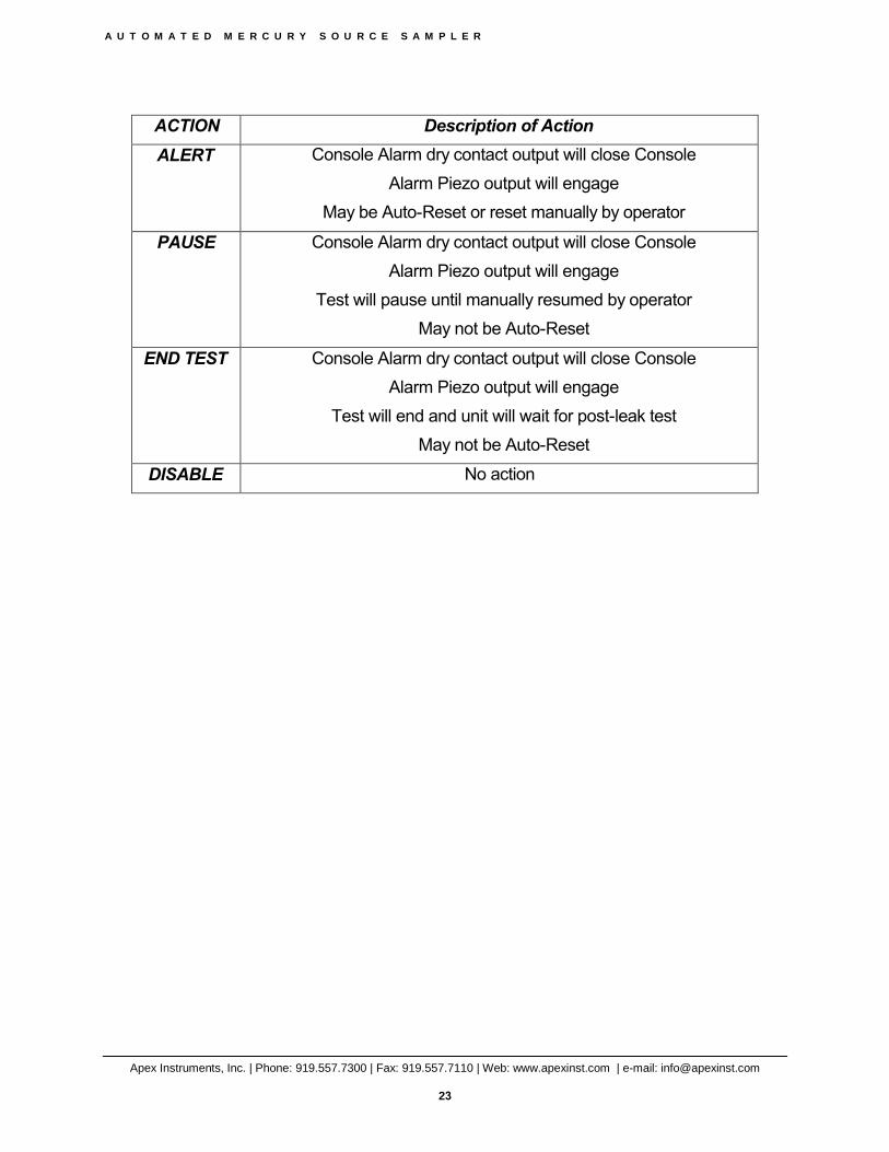
PROBE
10MMNU2-S-EXT
Stainless Steel (S) Tubing or C276 Alloy(C) (Indicate in Box 1), 3/4” O.D. x 4”, 6” OR 12” L (Indicate in Box 2) with two (2) 10mm stainless steel nuts, welded, and openings drilled at base of tubing.
8-8-4ET-S TEE, JUMP, 1/2x1/2x1/4 SS
8BLP8-S PLUG, 1/2", SS, FOR OPEN END T
10MMNU-S NUT, 10MM TUBE, Stainless Steel
10MMBLP-S PLUG, 10mm TU, SS – thread-on plug for end of probe, protects probe when not sampling
SR-2.625 Neoprene square ring, 2" ID x 2 5/8" OD x 3/16" tk, for cam-lock connectors
10M-F-TG FERRULE, 10MM, Single, Glass filled Teflon

A U T O M A T E D M E R C U R Y S O U R C E S A M P L E R
Apex Instruments, Inc. | Phone: 919.557.7300 | Fax: 919.557.7110 | Web: www.apexinst.com | e-mail: [email protected]
51
4NU-S NUT, 1/4 TUBE, Stainless Steel

A U T O M A T E D M E R C U R Y S O U R C E S A M P L E R
Apex Instruments, Inc. | Phone: 919.557.7300 | Fax: 919.557.7110 | Web: www.apexinst.com | e-mail: [email protected]
52
Appendix 2 Upgrading Firmware
From time to time, Apex Instruments may release updated device firmware for the XC-6000EM console. These firmware upgrades may add additional functionality or capabilities to the console, and may be required in order to use the latest version of the monitor / control client software. If the XC-6000 software displays a message regarding your firmware revision number, please contact Apex Instruments to get more information.
Current software and firmware versions may be obtained from Apex Instruments.
The XC-6000EM firmware may be programmed using a PC and the Apex Firmware Programming Cable. PLEASE NOTE: The drivers for the programming cable and the version of the STM-12B firmware most current at the time of shipment are installed along with the Apex software. Please install the Apex XC-6000 software before attempting to upgrade the firmware.
The Apex Firmware Programming Cable uses a USB Serial Converter similar to the one in the main console. When connecting the Firmware Programming Cable to the PC for the first time, the Found New Hardware Wizard may appear.
The programming cable is shipped with new consoles inside the XC-6000EM console.
Programming Cable
The programming cable has a 6-pin Molex connector and a 4-pin USB A connector. Please use the same steps as for connecting the STM-12B to the PC via USB. The programming cables use the same USB converter as the STM-12B so no additional drivers are necessary. The COM port installed may not be the same as the STM-12B virtual COM port, consult the Device Manager and note the COM number of the new serial port installed by the Apex Firmware Programming Cable.
Important Notes About Upgrading Firmware:
The older versions of the XC-6000 firmware lack several important new features of the current STM-12B consoles. These include the ability to set alarms based on test conditions, the optional ability to sample at flow rates above 1Lpm, and the provision for communication with the optional ModBus module. In addition, the calibration tables for the older versions may not be immediately compatible with the newer versions, and some conversion must be performed.

A U T O M A T E D M E R C U R Y S O U R C E S A M P L E R
Apex Instruments, Inc. | Phone: 919.557.7300 | Fax: 919.557.7110 | Web: www.apexinst.com | e-mail: [email protected]
53
Version #
Before upgrading your STM-12B firmware, please connect the console to your current software and make a note of the application and firmware version.
This can be found on the Config/Utils screen in the lower left corner.
Make a note of these version numbers. The new software CD will list the version included.
Once connected, enter the Config / Utilities screen and then the Calibration screen. Enter the word “enable” (no quotes all lowercase) into the protected password space on the Calibration screen. Press the “Save to File” button. Choose a location for your saved table, and give it a unique name.
IMPORTANT NOTE: Always save the STM-12B calibration table to a file before upgrading the console firmware.

A U T O M A T E D M E R C U R Y S O U R C E S A M P L E R
Apex Instruments, Inc. | Phone: 919.557.7300 | Fax: 919.557.7110 | Web: www.apexinst.com | e-mail: [email protected]
54
Calibration Screen
Programming the XC-6000EM Firmware
1. Ensure XC-6000EM console is powered off. Disconnect any connecting cables from theconsole, and remove the console from its rack enclosure. Remove the screws from the top ofthe unit and the on the outside left and right edges of the rear panel, and open the lid of theconsole by pulling the top/back cover towards the rear. The cover is mounted on a hinge at theback bottom of the console
Programming the DSP Processor – SKIP THIS STEP IF DSP IS ALREADY AT THE CURRENT VERSION!
2. Remove the 20-pin ribbon cable coming from the XC-6000EM TC/MUXboard. Reference: Figure DAC-1 below, item A.
3. Connect the 6-pin Molex connector on the end of the programming cable to the DAC boardheader labeled DSP Firm PgmReference: Figure DAC-1 below, item B.
Password
Calibration Screen 2
Save To File Restore from File
DGM Gamma

A U T O M A T E D M E R C U R Y S O U R C E S A M P L E R
Apex Instruments, Inc. | Phone: 919.557.7300 | Fax: 919.557.7110 | Web: www.apexinst.com | e-mail: [email protected]
55
4. Power on STM-12B console5. Navigate to the install location
default: C:\Apex\Firmware6. Execute dl.exe7. The Tiny Bootloader window will launch
DL.EXE - Tiny Bootloader
8. Click Browse and select ApexDSP_XX.hex (XX is the version) from the current directory9. Select the following options:
• Comm: 115200• Comm (use the COM number noted earlier)• Enable Options -> Reset PIC using RTS line
10. Click Write Flash11. When update is complete, Log window will read Write OK. The writing process should take
between 3 and 6 seconds. If you receive an “Error” power off the console then back on againthen press the write button.
12. Power off STM-12B console and remove 6-pin Molex connector on the end of theprogramming cable from the DAC board.
C
AB
C
AB

A U T O M A T E D M E R C U R Y S O U R C E S A M P L E R
Apex Instruments, Inc. | Phone: 919.557.7300 | Fax: 919.557.7110 | Web: www.apexinst.com | e-mail: [email protected]
56
Programming the Main Processor
13. Connect the 6-pin Molex connector on the end of the programming cable to DAC boardheader labeled Main Firm PgmReference: Figure DAC-1 below, item C.
14. If the Tiny Bootloader is already open skip to step 17. Navigate to the install locationdefault: C:\Apex\Firmware
15. Execute dl.exe16. The Tiny Bootloader window will launch
DL.EXE - Tiny Bootloader
17. Click Browse and select ApexMAIN_XX.hex (XX is the version)from the current directory18. Select the following options: (same as for DSP Processor)
• Comm: 115200• Comm (use the COM number noted earlier)• Enable Options -> Reset PIC using RTS line
19. Power on the STM-12B console20. Click Write Flash
C
AB

A U T O M A T E D M E R C U R Y S O U R C E S A M P L E R
Apex Instruments, Inc. | Phone: 919.557.7300 | Fax: 919.557.7110 | Web: www.apexinst.com | e-mail: [email protected]
57
21. When update is complete, Log window will read Write OK. The writing process should takebetween 45 and 60 seconds. If you receive an “Error” power off the console then back onagain then press the write button.
22. Power off STM-12B console and remove 6-pin Molex connector on the end of theprogramming cable from the DAC board.
23. Replace the 20-pin ribbon cable from the TC/MUX board (item A above)24. Power on the STM-12B console and connect using the XC-6000 MercSampler application.
The version number of the console should appear in the upper right of the application windowonce connected. Ensure that the version number that the console reports matches the versionnumber of the supplied firmware update.
After a successful upgrade:
Once the console has been upgraded, the calibration table will need to be converted to the new format. Connect to the console and enter the Config / Utilities screen. Press the “Set Clock” button to ensure that the software displayes the correct time and date set. Close the Config / Utilities screen and observe the date and time on the Main screen to make sure the time and date are correct and that the time is advancing. Then re-enter the Config / Utilities screen and go to the Calibration screen.
Enter “enable” (no quotes) in the password field and press the “Save” button. Once the table is saved, press “Save to File” and save a copy of the new table with a new filename. Press the Exit / Reset button to reset the console and apply the new calibration factors.
Older test profiles may cause errors when used with newer firmware. To avoid this, create new profiles for performing sample runs. If an older profile must be used, please step through the profile one screen at a time (press the “Next” button) and save the profile with a new filename. The profile should be automatically converted to the newest version.

A U T O M A T E D M E R C U R Y S O U R C E S A M P L E R
Apex Instruments, Inc. | Phone: 919.557.7300 | Fax: 919.557.7110 | Web: www.apexinst.com | e-mail: [email protected]
58
Electrical Subsystem
• The Source Sampler Console is factory-configured for 115 VAC / 60 Hz electrical power.Configuration for 220 VAC / 50 Hz operation is an available option.
• The AC electrical subsystem provides switch power to each circuit, controlled by twoswitches: MAIN and PROBE.
• All circuits are protected by a MAIN 15 Amp (10 Amp for the 220V system) circuit breaker.Additionally, the probe is protected by a 10 Amp breaker. These circuit breakers detect andinterrupt overload and short circuit conditions, providing an important safety factor. If thecircuit breaker opens, or “trips,” indicating interruption of the circuit, investigate and repair theelectrical fault, then reset the breaker by pressing the circuit breaker switch.
• Two custom-designed and manufactured circuit boards, a Data Acquisition and Control(DAC) board and Thermocouple (TC-MUX) board, are utilized.
Appendix 3

A U T O M A T E D M E R C U R Y S O U R C E S A M P L E R
Apex Instruments, Inc. | Phone: 919.557.7300 | Fax: 919.557.7110 | Web: www.apexinst.com | e-mail: [email protected]
59
Electrical Diagram
of XC-6000 M
ercSampler C
onsole.

A U T O M A T E D M E R C U R Y S O U R C E S A M P L E R
Apex Instruments, Inc. | Phone: 919.557.7300 | Fax: 919.557.7110 | Web: www.apexinst.com | e-mail: [email protected]
60
Appendix 4
Console Drawing Package

A U T O M A T E D M E R C U R Y S O U R C E S A M P L E R
The
Mer
cSam
pler
Con
sole
is c
ompr
ised
of p
lum
bing
and
ele
ctric
al (i
nclu
ding
th
erm
ocou
ple
and
elec
troni
c ci
rcui
ts) s
ubsy
stem
s th
at w
ork
toge
ther
to g
ive
appr
opria
te c
ontro
l and
feed
back
.
Syst
em P
lum
bing
Plu
mbi
ng F
low
Dia
gram
of X
C-6000E
M M
ercS
ampl
er C
onso
le.
Apex Instruments, Inc. | Phone: 919.557.7300 | Fax: 919.557.7110 | Web: www.apexinst.com | e-mail: [email protected]
61
Appendix 5
System Plumbing Diagram
A U T O M A T E D M E R C U R Y S O U R C E S A M P L E R
Apex Instruments, Inc. | Phone: 919.557.7300 | Fax: 919.557.7110 | Web: www.apexinst.com | e-mail: [email protected]
62
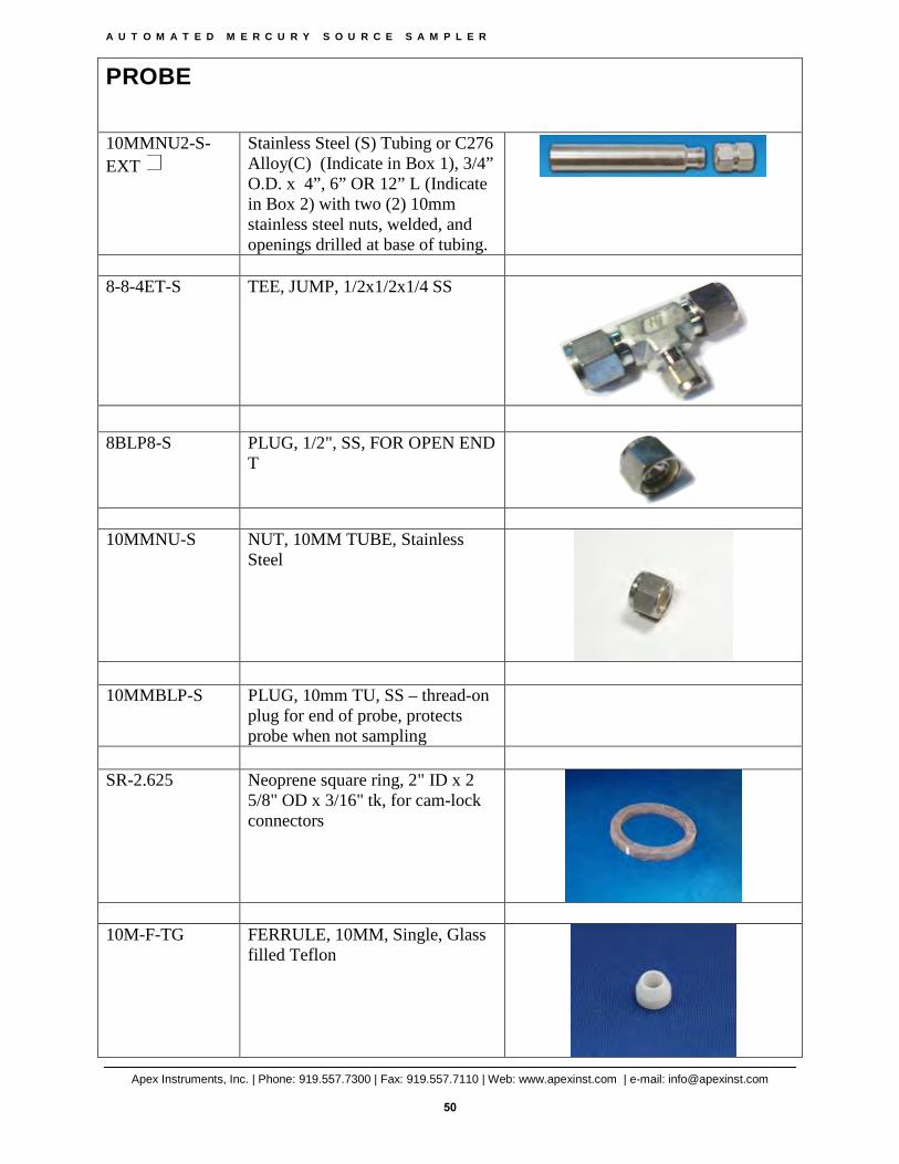
Appendix 6
Sorbent Canister Assembly Fill Ratios