
Manual 888 Titrando 8.888.8002EN
67
888 Titrando Manual 8.888.8002EN
Transcript of Manual 888 Titrando 8.888.8002EN
888 Titrando
Manual8.888.8002EN

Metrohm AGCH-9101 HerisauSwitzerlandPhone +41 71 353 85 85Fax +41 71 353 89 [email protected]
888 Titrando
Manual
8.888.8002EN 02.2009 ek
TeachwareMetrohm AGCH-9101 [email protected]
This documentation is protected by copyright. All rights reserved.
Although all the information given in this documentation has beenchecked with great care, errors cannot be entirely excluded. Should younotice any mistakes please send us your comments using the addressgiven above.
■■■■■■■■■■■■■■■■■■■■■■ Table of contents
888 Titrando ■■■■■■■■ III
Table of contents
1 Introduction 1
1.1 The Titrando system ............................................................. 1
1.2 Instrument description ........................................................ 2
1.3 Titration modes — Measuring modes — Dosing com-mands .................................................................................... 3
1.4 Model versions ...................................................................... 4
1.5 About the documentation ................................................... 41.5.1 Symbols and conventions ........................................................ 4
1.6 Safety instructions ................................................................ 51.6.1 General notes on safety ........................................................... 51.6.2 Electrical safety ........................................................................ 51.6.3 Working with liquids ................................................................ 61.6.4 Recycling and disposal ............................................................. 6
2 Overview of the instrument 8
3 Installation 10
3.1 Setting up the instrument .................................................. 103.1.1 Packaging .............................................................................. 103.1.2 Checks .................................................................................. 103.1.3 Location ................................................................................ 10
3.2 Connecting controller ......................................................... 103.2.1 Operation .............................................................................. 10
3.3 Connecting MSB devices ................................................... 143.3.1 Connecting dosing devices .................................................... 153.3.2 Connecting a stirrer or titration stand .................................... 163.3.3 Connecting a remote box ...................................................... 17
3.4 Connecting USB devices ..................................................... 183.4.1 General ................................................................................. 183.4.2 Connecting a printer .............................................................. 183.4.3 Connecting a balance ............................................................ 193.4.4 Connecting a PC keyboard (only Titrando with Touch Con-
trol) ....................................................................................... 213.4.5 Connecting a barcode reader ................................................. 223.4.6 Connecting a USB hub ........................................................... 233.4.7 Connecting a Bluetooth® adapter .......................................... 24
3.5 Connecting sensors ............................................................ 263.5.1 General ................................................................................. 263.5.2 Connecting a pH, redox or ISE electrode ................................ 263.5.3 Connecting a reference electrode .......................................... 26
Table of contents ■■■■■■■■■■■■■■■■■■■■■■
IV ■■■■■■■■ 888 Titrando
3.5.4 Connecting a temperature sensor or an electrode with inte-grated temperature sensor .................................................... 27
3.5.5 Connecting a polarizable electrode ........................................ 283.5.6 Connecting an iConnect ........................................................ 283.5.7 Differential potentiometry ...................................................... 293.5.8 Setting up a titration vessel .................................................... 29
4 Working with the exchange unit 31
5 Handling and maintenance 33
5.1 General information ........................................................... 335.1.1 Care ...................................................................................... 335.1.2 Maintenance by Metrohm Service .......................................... 33
5.2 Quality Management and validation with Metrohm ....... 34
6 Troubleshooting 35
6.1 Problems ............................................................................. 35
7 Appendix 37
7.1 Remote interface ................................................................ 377.1.1 Pin assignment of the remote interface .................................. 37
8 Technical data 40
8.1 Measuring interface ........................................................... 408.1.1 Potentiometry ........................................................................ 408.1.2 Temperature .......................................................................... 408.1.3 Polarizer ................................................................................ 41
8.2 Internal dosing device ........................................................ 42
8.3 Mains connection ............................................................... 42
8.4 Safety specifications ........................................................... 42
8.5 Electromagnetic compatibility (EMC) ................................ 42
8.6 Ambient temperature ......................................................... 43
8.7 Reference conditions .......................................................... 43
8.8 Dimensions .......................................................................... 43
8.9 Interfaces ............................................................................. 43
9 Conformity and warranty 45
9.1 Declaration of Conformity ................................................. 45
9.2 Quality Management Principles ........................................ 46
9.3 Warranty (guarantee) ......................................................... 47
■■■■■■■■■■■■■■■■■■■■■■ Table of contents
888 Titrando ■■■■■■■■ V
10 Accessories 48
10.1 Scope of delivery ................................................................ 4810.1.1 888 Titrando with Touch Control 2.888.0110 ........................ 4810.1.2 888 Titrando with tiamo light 2.888.0210 ............................. 52
Index 58
Table of figures ■■■■■■■■■■■■■■■■■■■■■■
VI ■■■■■■■■ 888 Titrando
Table of figures
Figure 1 The Titrando system .......................................................................... 1Figure 2 Front 888 Titrando ............................................................................ 8Figure 3 Rear 888 Titrando ............................................................................. 9Figure 4 Connecting a Touch Control ............................................................ 11Figure 5 Connecting a computer ................................................................... 13Figure 6 MSB connections ............................................................................ 14Figure 7 Connecting a dosing device ............................................................. 16Figure 8 Connecting MSB stirrer .................................................................... 16Figure 9 Rod stirrer and titration stand .......................................................... 17Figure 10 Connecting a remote box ................................................................ 18Figure 11 Connecting a printer ....................................................................... 19Figure 12 Connecting a balance ...................................................................... 21Figure 13 Connecting a pH, redox or ISE electrode .......................................... 26Figure 14 Connecting a reference electrode .................................................... 27Figure 15 Connecting a temperature sensor or an electrode with integrated tem-
perature sensor ............................................................................... 27Figure 16 Connecting a polarizable electrode .................................................. 28Figure 17 Connecting an iConnect .................................................................. 28Figure 18 Connecting an electrode to the iConnect ........................................ 29Figure 19 Schematic configuration of magnetic stirrer, electrode and buret tip
(stirring direction counterclockwise) ................................................. 30Figure 20 Schematic configuration of magnetic stirrer, electrode and buret tip
(stirring direction clockwise) ............................................................ 30Figure 21 Attaching the exchange unit ........................................................... 31Figure 22 Connectors of the remote box ......................................................... 37Figure 23 Pin assignment of remote socket and plug ...................................... 37
■■■■■■■■■■■■■■■■■■■■■■ 1 Introduction
888 Titrando ■■■■■■■■ 1
1 Introduction
1.1 The Titrando system
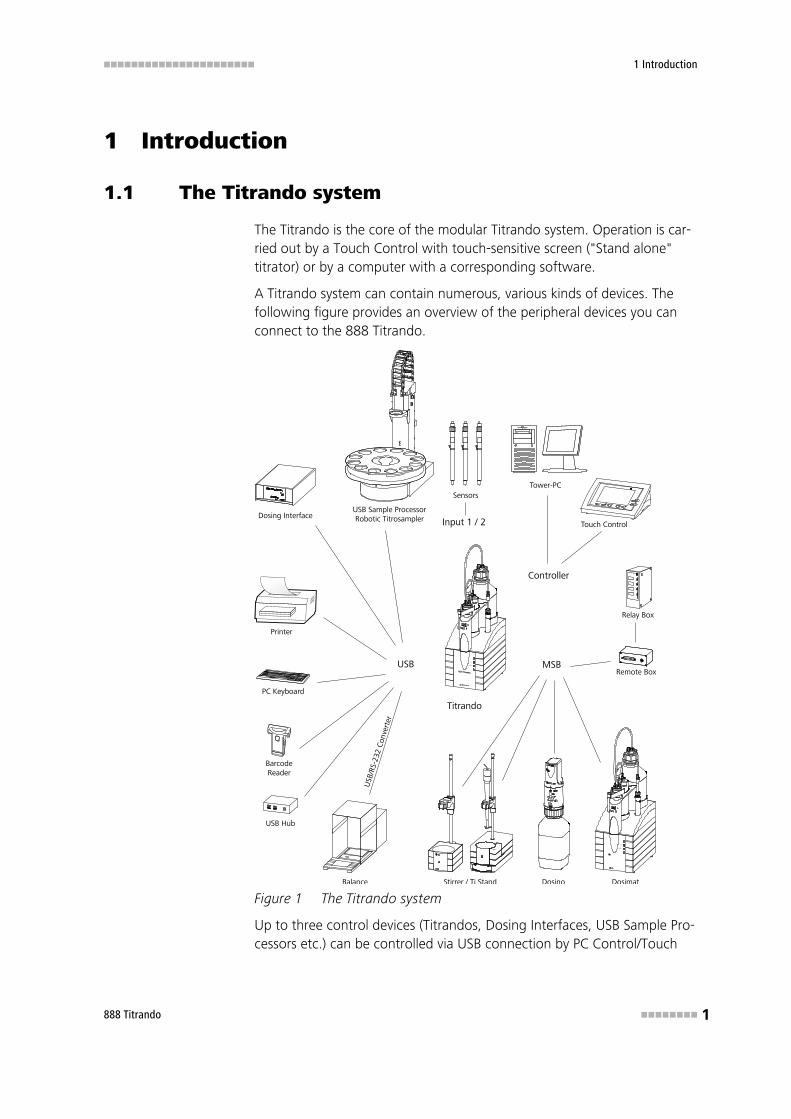
The Titrando is the core of the modular Titrando system. Operation is car-ried out by a Touch Control with touch-sensitive screen ("Stand alone"titrator) or by a computer with a corresponding software.
A Titrando system can contain numerous, various kinds of devices. Thefollowing figure provides an overview of the peripheral devices you canconnect to the 888 Titrando.
MSBUSB
Controller
Input 1 / 2
Sensors
PC Keyboard
BarcodeReader
USB Hub
USB
/RS-
232
Con
vert
er
Balance
Touch Control
USB Sample ProcessorRobotic Titrosampler
Printer
Relay Box
Remote Box
Dosing Interface
Stirrer / Ti Stand Dosino Dosimat
On
Status
805Dosima
Metroh
Titrando
Tower-PC
On
Status
Figure 1 The Titrando system
Up to three control devices (Titrandos, Dosing Interfaces, USB Sample Pro-cessors etc.) can be controlled via USB connection by PC Control/Touch
1.2 Instrument description ■■■■■■■■■■■■■■■■■■■■■■
2 ■■■■■■■■ 888 Titrando
Control. With the tiamo software the system can arbitrarily be extendedwith control devices.
You can request information on special applications in the "ApplicationBulletins" and "Application Notes"; available free of charge via theMetrohm agent responsible. Various monographs on the subjects of titra-tion techniques and electrodes are also available.
Updating the device software is described in the manual for PC Control/Touch Control or in the tiamo help, respectively.
1.2 Instrument description
The 888 Titrando has the following characteristics:
■ OperationOperation is carried out by means of a touch-sensitive Touch Controlor with a high-performance PC software, e.g. tiamo.
■ DosingAn internal dosing drive for exchange units.
■ MSB connectorsFour MSB connectors (Metrohm Serial Bus) to control dosing devices(Dosimat with exchange unit or Dosino with dosing unit), stirrer ortitration stand and remote boxes.
■ USB connectorsTwo USB connectors, through which devices such as printers, PC key-boards, barcode readers or additional control devices (Titrando, USBSample Processor, Dosing Interface, etc.) can be connected.
■ Measuring interfaceA measuring interface with one high-ohm measuring input Ind. for pH,redox or ISE electrodes, one measuring input Ref. for a separate refer-ence electrode, one measuring input Temp. for temperature sensors(Pt1000 or NTC), one measuring input Pol. for polarizable electrodeand one connector iConnect for an iConnect.
■■■■■■■■■■■■■■■■■■■■■■ 1 Introduction
888 Titrando ■■■■■■■■ 3
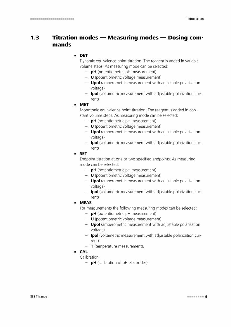
1.3 Titration modes — Measuring modes — Dosing com-mands
■ DETDynamic equivalence point titration. The reagent is added in variablevolume steps. As measuring mode can be selected:
– pH (potentiometric pH measurement)– U (potentiometric voltage measurement)– Upol (amperometric measurement with adjustable polarization
voltage)– Ipol (voltametric measurement with adjustable polarization cur-
rent)■ MET
Monotonic equivalence point titration. The reagent is added in con-stant volume steps. As measuring mode can be selected:
– pH (potentiometric pH measurement)– U (potentiometric voltage measurement)– Upol (amperometric measurement with adjustable polarization
voltage)– Ipol (voltametric measurement with adjustable polarization cur-
rent)■ SET
Endpoint titration at one or two specified endpoints. As measuringmode can be selected:
– pH (potentiometric pH measurement)– U (potentiometric voltage measurement)– Upol (amperometric measurement with adjustable polarization
voltage)– Ipol (voltametric measurement with adjustable polarization cur-
rent)■ MEAS
For measurements the following measuring modes can be selected:– pH (potentiometric pH measurement)– U (potentiometric voltage measurement)– Upol (amperometric measurement with adjustable polarization
voltage)– Ipol (voltametric measurement with adjustable polarization cur-
rent)– T (temperature measurement),
■ CALCalibration.
– pH (calibration of pH electrodes)
1.4 Model versions ■■■■■■■■■■■■■■■■■■■■■■
4 ■■■■■■■■ 888 Titrando
■ Dosing commandsThe following commands for dosing can be selected:
– ADD (adding a predefined volume)– PREP (Rinsing the cylinder and tubings of an exchange or dos-
ing unit)– EMPTY (for emptying cylinder and tubings)
1.4 Model versions
The 888 Titrando is available in two different model versions:
2.888.0110 Titrando with Touch Control
2.888.0210 Titrando with tiamo light
1.5 About the documentation
Caution
Please read through this documentation carefully before putting theinstrument into operation. The documentation contains informationand warnings which have to be followed by the user in order to ensuresafe operation of the instrument.
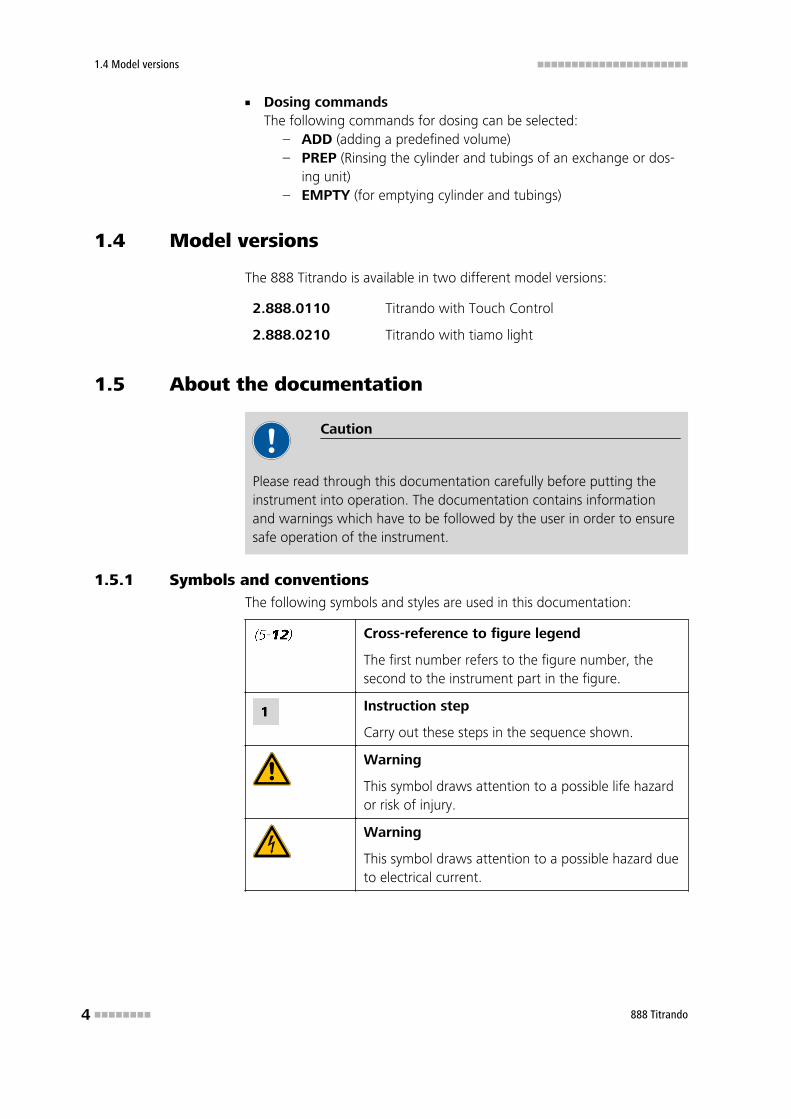
1.5.1 Symbols and conventionsThe following symbols and styles are used in this documentation:
Cross-reference to figure legend
The first number refers to the figure number, thesecond to the instrument part in the figure.
Instruction step
Carry out these steps in the sequence shown.
Warning
This symbol draws attention to a possible life hazardor risk of injury.
Warning
This symbol draws attention to a possible hazard dueto electrical current.
■■■■■■■■■■■■■■■■■■■■■■ 1 Introduction
888 Titrando ■■■■■■■■ 5
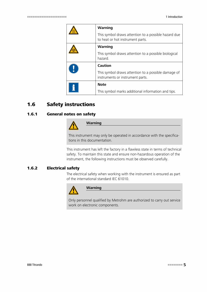
Warning
This symbol draws attention to a possible hazard dueto heat or hot instrument parts.
Warning
This symbol draws attention to a possible biologicalhazard.
Caution
This symbol draws attention to a possible damage ofinstruments or instrument parts.
Note
This symbol marks additional information and tips.
1.6 Safety instructions
1.6.1 General notes on safety
Warning
This instrument may only be operated in accordance with the specifica-tions in this documentation.
This instrument has left the factory in a flawless state in terms of technicalsafety. To maintain this state and ensure non-hazardous operation of theinstrument, the following instructions must be observed carefully.
1.6.2 Electrical safetyThe electrical safety when working with the instrument is ensured as partof the international standard IEC 61010.
Warning
Only personnel qualified by Metrohm are authorized to carry out servicework on electronic components.
1.6 Safety instructions ■■■■■■■■■■■■■■■■■■■■■■
6 ■■■■■■■■ 888 Titrando
Warning
Never open the housing of the instrument. The instrument could bedamaged by this. There is also a risk of serious injury if live componentsare touched.
There are no parts inside the housing which can be serviced or replacedby the user.
Mains voltage
Warning
An incorrect mains voltage can damage the instrument.
Only operate this instrument with a mains voltage specified for it (seerear panel of the instrument).
Protection against electrostatic charges
Warning
Electronic components are sensitive to electrostatic charges and can bedestroyed by discharges.
Always pull the mains cable out of the mains connection socket beforeconnecting or disconnecting electrical appliances on the rear panel ofthe instrument.
1.6.3 Working with liquids
Caution
Periodically check all system connections for leaks. Observe the relevantregulations in respect to working with flammable and/or toxic fluidsand their disposal.
1.6.4 Recycling and disposalThis product is covered by European Directive 2002/96/EC, WEEE – Wastefrom Electrical and Electronic Equipment.
The correct disposal of your old equipment will help to prevent negativeeffects on the environment and public health.
■■■■■■■■■■■■■■■■■■■■■■ 1 Introduction
888 Titrando ■■■■■■■■ 7
More details about the disposal of your old equipment can be obtainedfrom your local authorities, from waste disposal companies or from yourlocal dealer.
■■■■■■■■■■■■■■■■■■■■■■
8 ■■■■■■■■ 888 Titrando
2 Overview of the instrument
iTrode ready
On
Status
888 Titrando
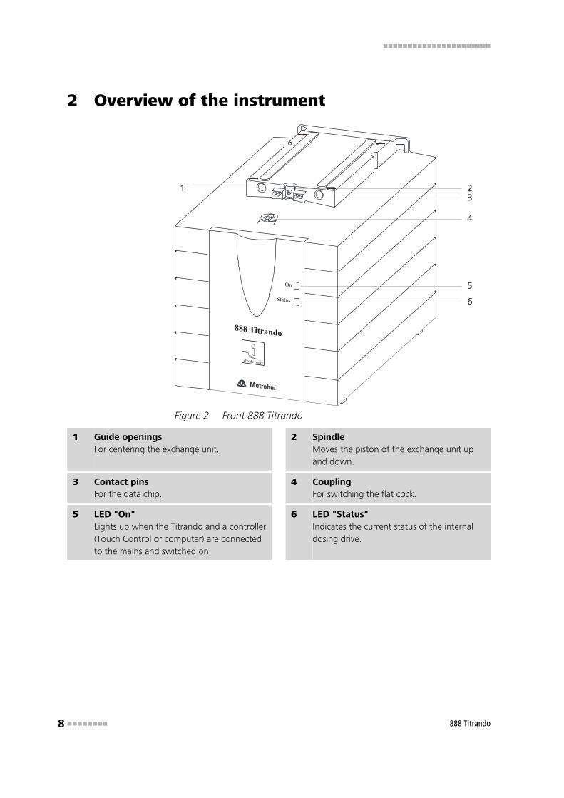
Figure 2 Front 888 Titrando
1 Guide openingsFor centering the exchange unit.
2 SpindleMoves the piston of the exchange unit upand down.
3 Contact pinsFor the data chip.
4 CouplingFor switching the flat cock.
5 LED "On"Lights up when the Titrando and a controller(Touch Control or computer) are connectedto the mains and switched on.
6 LED "Status"Indicates the current status of the internaldosing drive.

■■■■■■■■■■■■■■■■■■■■■■ 2 Overview of the instrument
888 Titrando ■■■■■■■■ 9
Figure 3 Rear 888 Titrando
1 Type plateContains specifications concerning mainsvoltage, instrument type and serial number.
2 USB connector (USB 1 and USB 2)USB ports (type A) for connecting printer,keyboard, barcode reader, additional Titran-dos, USB Sample Processor, etc.
3 Controller connector (Controller)Connection of a Touch Control or PC withinstalled PC software. Mini DIN, 9-pin.
4 MSB connector (MSB 1 to MSB 4)Metrohm Serial Bus. For connecting externaldosing devices, stirrers to remote boxes.Mini DIN, 9-pin.
5 Mains connection socket 6 Measuring interface 1 (Input 1)
7 Electrode connector (Ind.)For connecting pH, redox or ISE electrodeswith integrated or separated reference elec-trode. Socket F.
8 Electrode connector (Ref.)For connecting reference electrodes, e.g.Ag/AgCl reference electrode. Socket B, 4mm.
9 Temperature sensor connector (Temp.)For connecting temperature sensors, e.g.Pt1000 or NTC sensors. Two B sockets, 2mm.
10 Electrode connector (Pol.)For connecting polarizable electrodes, e.g.double Pt electrodes. Socket F.
11 iConnect connector (iConnect)For connecting electrodes with integrateddata chip (iTrodes).
3.1 Setting up the instrument ■■■■■■■■■■■■■■■■■■■■■■
10 ■■■■■■■■ 888 Titrando
3 Installation
3.1 Setting up the instrument
3.1.1 PackagingThe instrument is supplied in highly protective special packaging togetherwith the separately packed accessories. Keep this packaging, as only thisensures safe transportation of the instrument.
3.1.2 ChecksImmediately after receipt, check whether the shipment has arrived com-plete and without damage by comparing it with the delivery note.
3.1.3 LocationThe instrument has been developed for operation indoors and may not beused in explosive environments.
Place the instrument in a location of the laboratory which is suitable foroperation, free of vibrations, protected from corrosive atmosphere, andcontamination by chemicals.
The instrument should be protected against excessive temperature fluctu-ations and direct sunlight.
3.2 Connecting controller
3.2.1 OperationTwo different versions are available for operating the 888 Titrando:
■ With a Touch Control with a touch-sensitive screen. It forms a "stand-alone" instrument together with the 888 Titrando.
■ A computer enables handling of the 888 Titrando with the aid of a PCsoftware, e.g. PC Control.
Caution
Take care to ensure that the mains cable is pulled out of the mains con-nection socket before either setting up or disconnecting connectionsbetween the instruments.
■■■■■■■■■■■■■■■■■■■■■■ 3 Installation
888 Titrando ■■■■■■■■ 11
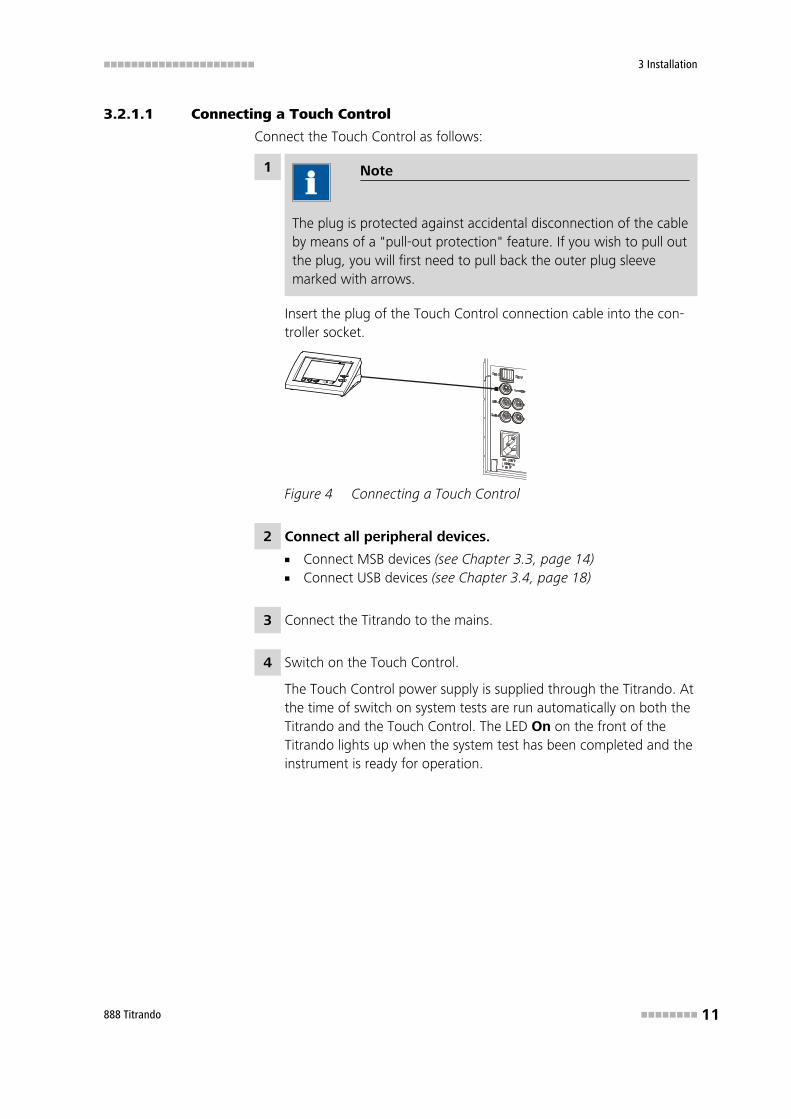
3.2.1.1 Connecting a Touch Control
Connect the Touch Control as follows:
1 Note
The plug is protected against accidental disconnection of the cableby means of a "pull-out protection" feature. If you wish to pull outthe plug, you will first need to pull back the outer plug sleevemarked with arrows.
Insert the plug of the Touch Control connection cable into the con-troller socket.
Figure 4 Connecting a Touch Control
2 Connect all peripheral devices.
■ Connect MSB devices (see Chapter 3.3, page 14)■ Connect USB devices (see Chapter 3.4, page 18)
3 Connect the Titrando to the mains.
4 Switch on the Touch Control.
The Touch Control power supply is supplied through the Titrando. Atthe time of switch on system tests are run automatically on both theTitrando and the Touch Control. The LED On on the front of theTitrando lights up when the system test has been completed and theinstrument is ready for operation.
3.2 Connecting controller ■■■■■■■■■■■■■■■■■■■■■■
12 ■■■■■■■■ 888 Titrando
Caution
The Touch Control must be shut down properly by switching off withthe ON/OFF switch on the rear of the instrument before the currentsupply is interrupted. If this is not done, then there is a danger of dataloss. Because of the fact that the power supply for the Touch Control isprovided through the Titrando, you must never separate the Titrandofrom the mains (e.g. by switching off with a connector strip) before youhave switched off the Touch Control.
If you would prefer not to position the Touch Control directly next to theTitrando, then you can lengthen the connection between Titrando andTouch Control using the 6.2151.010 cable. The maximum connectionlength permitted is 5 m.
3.2.1.2 Connecting a computer
The 888 Titrando requires a USB connection to a computer in order to beable to be controlled by a PC software. When a controller cable6.2151.000 is used, the instrument can be connected directly, either to aUSB socket on a computer, to a connected USB hub or to a differentMetrohm control instrument.
Cable connection and driver installation
A driver installation is required in order to ensure that the 888 Titrando isrecognized by the PC software. To accomplish this, you must comply withthe procedures specified. The following steps are necessary:
1 Install software
■ Insert the PC software installation CD and carry out the installa-tion program directions.
■ Exit the program if you have started it after the installation.
2 Establish cable connections
■ Connect all peripheral devices to the instrument.– Connect MSB devices (see Chapter 3.3, page 14)– Connect USB devices (see Chapter 3.4, page 18)
■ Connect the instrument to the mains supply if you have notalready done this.The LED On on the 888 Titrando is not yet illuminated!
■ Connect the instrument to a USB connector (Type A) of your com-puter (see manual of your computer). The 6.2151.000 cable isused for this purpose.
■■■■■■■■■■■■■■■■■■■■■■ 3 Installation
888 Titrando ■■■■■■■■ 13
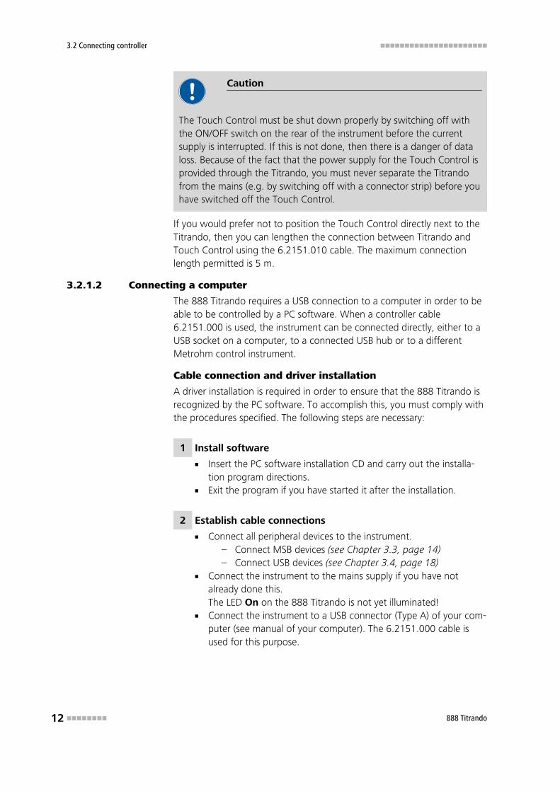
6.2151.000
Figure 5 Connecting a computer
For Windows 2000: the instrument is recognized and the driver isinstalled automatically.
For Windows XP: the instrument is recognized and the installationassistant for the driver is started automatically. Select the option"Install software automatically" and click on [Next >]. Exit the assis-tant with [Finish].
For Windows Vista: the instrument is recognized and the installa-tion assistant for the driver is started automatically. Select the option"Find and install driver software". Agree to all of the requests thatfollow. The installation assistant will be exited automatically.
The On LED on the 888 Titrando lights up when the driver installa-tion has been exited and the device is ready for operation.
Note
The plug on the instrument end of the 6.2151.000 controller cable isprotected against accidental disconnection by means of a pull-out pro-tection feature. If you wish to pull out the plug, you will first need topull back the outer plug sleeve marked with arrows.
Registering and configuring the instrument in the PC soft-ware
The instrument must be registered in the configuration of your PC soft-ware. Once that has been done, you can then configure it according toyour requirements. Proceed as follows:
3.3 Connecting MSB devices ■■■■■■■■■■■■■■■■■■■■■■
14 ■■■■■■■■ 888 Titrando
1 Set up the instrument
■ Start up PC software.The instrument is recognized automatically. The configuration dia-log for the instrument is displayed.
■ Make configuration settings for the instrument and its connec-tors.
More detailed information concerning the configuration of theinstrument can be found in the documentation for the respective PCsoftware.
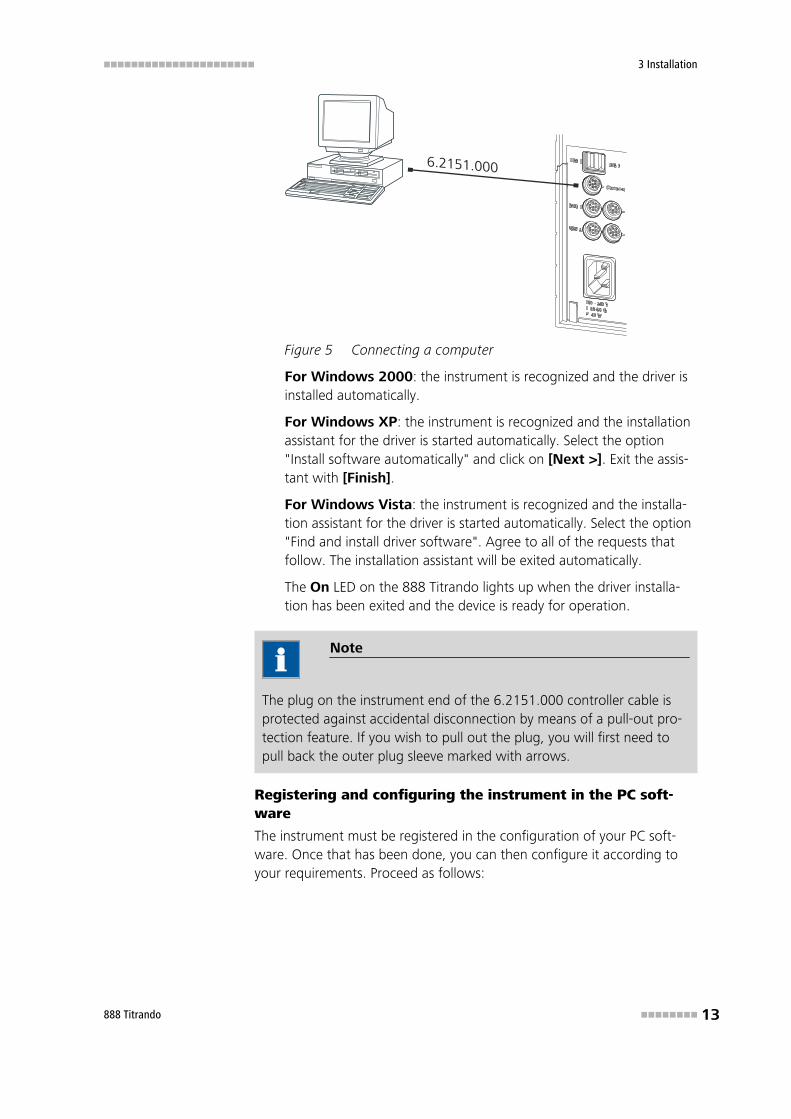
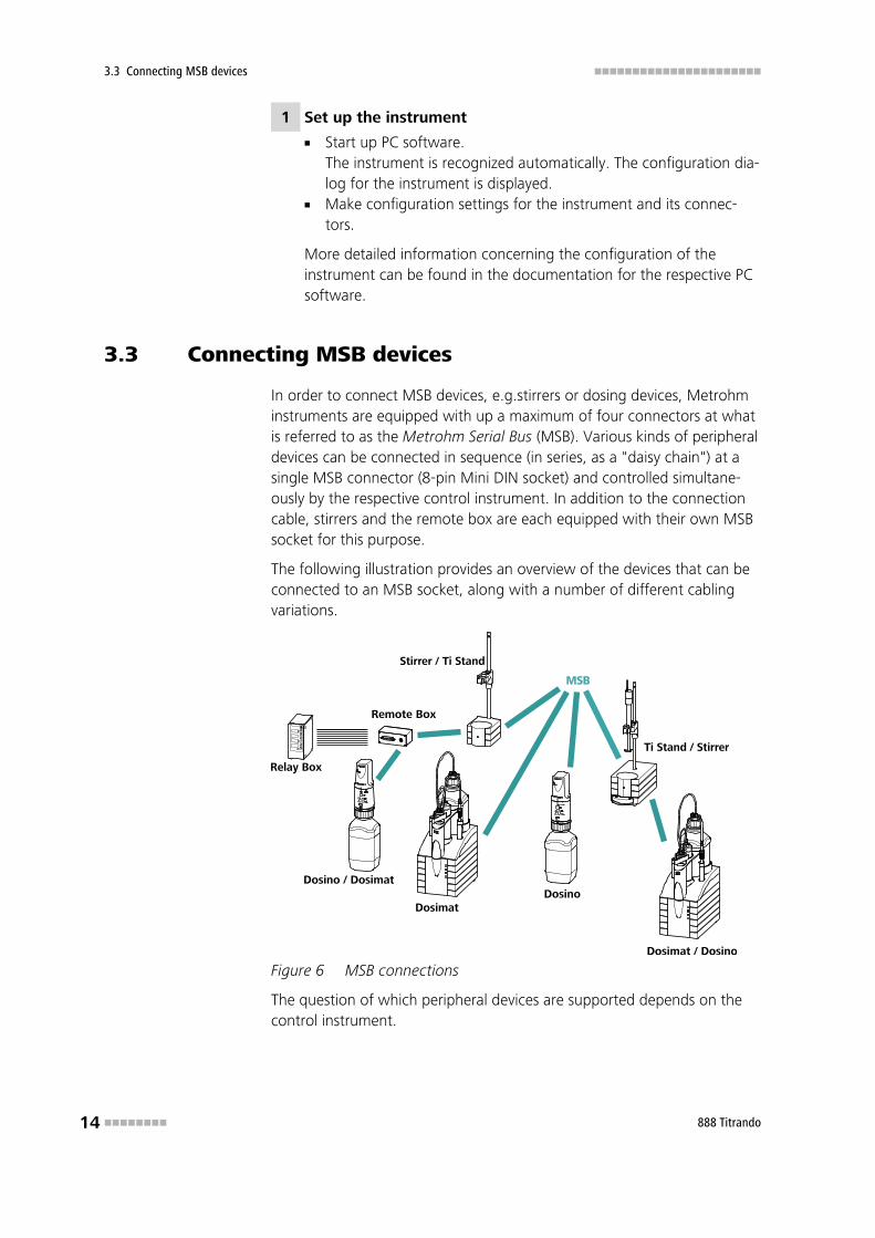
3.3 Connecting MSB devices
In order to connect MSB devices, e.g.stirrers or dosing devices, Metrohminstruments are equipped with up a maximum of four connectors at whatis referred to as the Metrohm Serial Bus (MSB). Various kinds of peripheraldevices can be connected in sequence (in series, as a "daisy chain") at asingle MSB connector (8-pin Mini DIN socket) and controlled simultane-ously by the respective control instrument. In addition to the connectioncable, stirrers and the remote box are each equipped with their own MSBsocket for this purpose.
The following illustration provides an overview of the devices that can beconnected to an MSB socket, along with a number of different cablingvariations.
MSB
Stirrer / Ti Stand
Dosimat / Dosino
Dosimat
Remote Box
Dosino / DosimatDosino
Relay Box
Ti Stand / Stirrer
Figure 6 MSB connections
The question of which peripheral devices are supported depends on thecontrol instrument.
■■■■■■■■■■■■■■■■■■■■■■ 3 Installation
888 Titrando ■■■■■■■■ 15
Note
When connecting MSB devices together, the following must beobserved:
■ Only one device of the same type can be used at a single MSB con-nector at one time.
■ Type 700 Dosino and 685 Dosimat dosing devices cannot be con-nected together with other MSB instruments on a shared connector.These dosing devices must be connected separately.
Caution
Exit the control software before you plug MSB instruments in. The con-trol instrument recognizes when it is switched on which instrument isconnected at which MSB connector. The operating unit or the controlsoftware enters the connected MSB devices into the system configura-tion (Device manager).
MSB connections can be extended with the 6.2151.010 cable. The lengthof the connection must not exceed a maximum of 15 m.
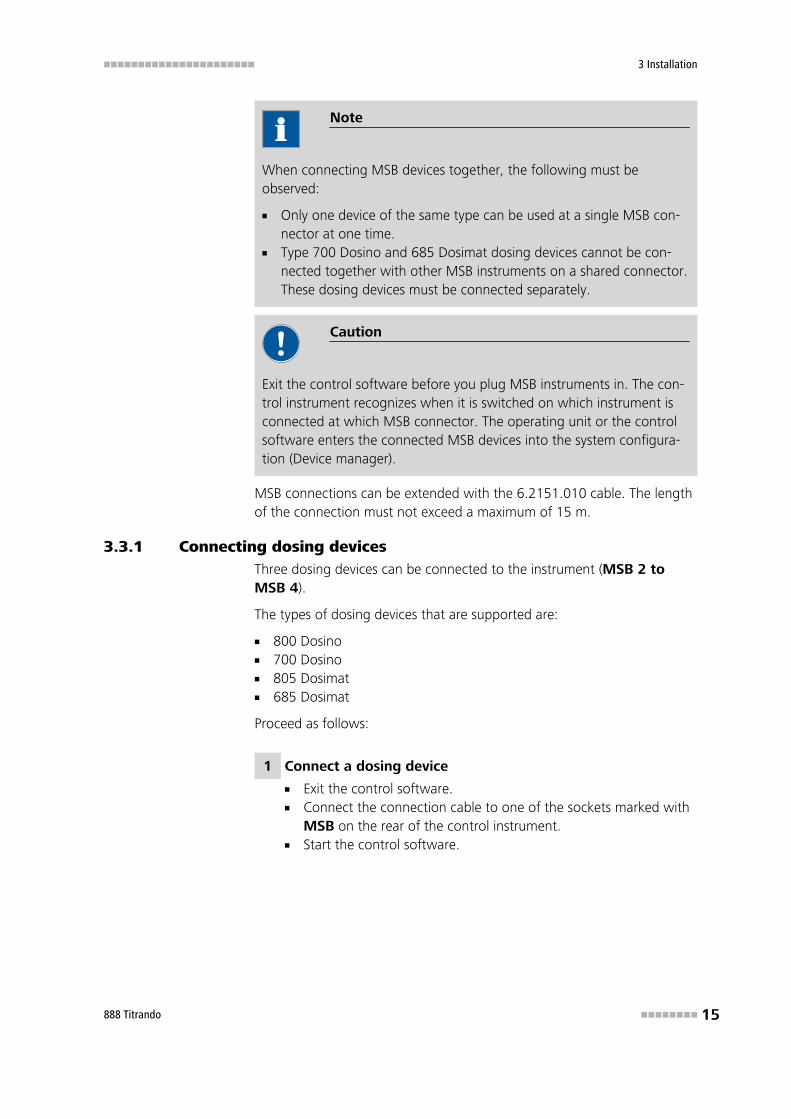
3.3.1 Connecting dosing devicesThree dosing devices can be connected to the instrument (MSB 2 toMSB 4).
The types of dosing devices that are supported are:
■ 800 Dosino■ 700 Dosino■ 805 Dosimat■ 685 Dosimat
Proceed as follows:
1 Connect a dosing device
■ Exit the control software.■ Connect the connection cable to one of the sockets marked with
MSB on the rear of the control instrument.■ Start the control software.
3.3 Connecting MSB devices ■■■■■■■■■■■■■■■■■■■■■■
16 ■■■■■■■■ 888 Titrando
Figure 7 Connecting a dosing device
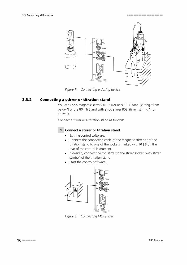
3.3.2 Connecting a stirrer or titration standYou can use a magnetic stirrer 801 Stirrer or 803 Ti Stand (stirring "frombelow") or the 804 Ti Stand with a rod stirrer 802 Stirrer (stirring "fromabove").
Connect a stirrer or a titration stand as follows:
1 Connect a stirrer or titration stand
■ Exit the control software.■ Connect the connection cable of the magnetic stirrer or of the
titration stand to one of the sockets marked with MSB on therear of the control instrument.
■ If desired, connect the rod stirrer to the stirrer socket (with stirrersymbol) of the titration stand.
■ Start the control software.
Figure 8 Connecting MSB stirrer
■■■■■■■■■■■■■■■■■■■■■■ 3 Installation
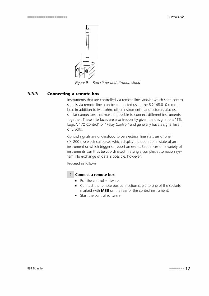
888 Titrando ■■■■■■■■ 17
Figure 9 Rod stirrer and titration stand
3.3.3 Connecting a remote boxInstruments that are controlled via remote lines and/or which send controlsignals via remote lines can be connected using the 6.2148.010 remotebox. In addition to Metrohm, other instrument manufacturers also usesimilar connectors that make it possible to connect different instrumentstogether. These interfaces are also frequently given the designations "TTLLogic", "I/O Control" or "Relay Control" and generally have a signal levelof 5 volts.
Control signals are understood to be electrical line statuses or brief(> 200 ms) electrical pulses which display the operational state of aninstrument or which trigger or report an event. Sequences on a variety ofinstruments can thus be coordinated in a single complex automation sys-tem. No exchange of data is possible, however.
Proceed as follows:
1 Connect a remote box
■ Exit the control software.■ Connect the remote box connection cable to one of the sockets
marked with MSB on the rear of the control instrument.■ Start the control software.
3.4 Connecting USB devices ■■■■■■■■■■■■■■■■■■■■■■
18 ■■■■■■■■ 888 Titrando
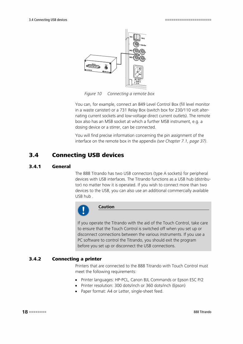
Figure 10 Connecting a remote box
You can, for example, connect an 849 Level Control Box (fill level monitorin a waste canister) or a 731 Relay Box (switch box for 230/110 volt alter-nating current sockets and low-voltage direct current outlets). The remotebox also has an MSB socket at which a further MSB instrument, e.g. adosing device or a stirrer, can be connected.
You will find precise information concerning the pin assignment of theinterface on the remote box in the appendix (see Chapter 7.1, page 37).
3.4 Connecting USB devices
3.4.1 GeneralThe 888 Titrando has two USB connectors (type A sockets) for peripheraldevices with USB interfaces. The Titrando functions as a USB hub (distribu-tor) no matter how it is operated. If you wish to connect more than twodevices to the USB, you can also use an additional commercially availableUSB hub .
Caution
If you operate the Titrando with the aid of the Touch Control, take careto ensure that the Touch Control is switched off when you set up ordisconnect connections between the various instruments. If you use aPC software to control the Titrando, you should exit the programbefore you set up or disconnect the USB connections.
3.4.2 Connecting a printerPrinters that are connected to the 888 Titrando with Touch Control mustmeet the following requirements:
■ Printer languages: HP-PCL, Canon BJL Commands or Epson ESC P/2■ Printer resolution: 300 dots/inch or 360 dots/inch (Epson)■ Paper format: A4 or Letter, single-sheet feed.
■■■■■■■■■■■■■■■■■■■■■■ 3 Installation
888 Titrando ■■■■■■■■ 19
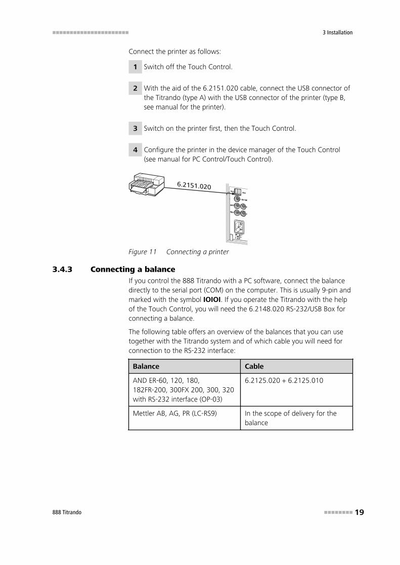
Connect the printer as follows:
1 Switch off the Touch Control.
2 With the aid of the 6.2151.020 cable, connect the USB connector ofthe Titrando (type A) with the USB connector of the printer (type B,see manual for the printer).
3 Switch on the printer first, then the Touch Control.
4 Configure the printer in the device manager of the Touch Control(see manual for PC Control/Touch Control).
Figure 11 Connecting a printer
3.4.3 Connecting a balanceIf you control the 888 Titrando with a PC software, connect the balancedirectly to the serial port (COM) on the computer. This is usually 9-pin andmarked with the symbol IOIOI. If you operate the Titrando with the helpof the Touch Control, you will need the 6.2148.020 RS-232/USB Box forconnecting a balance.
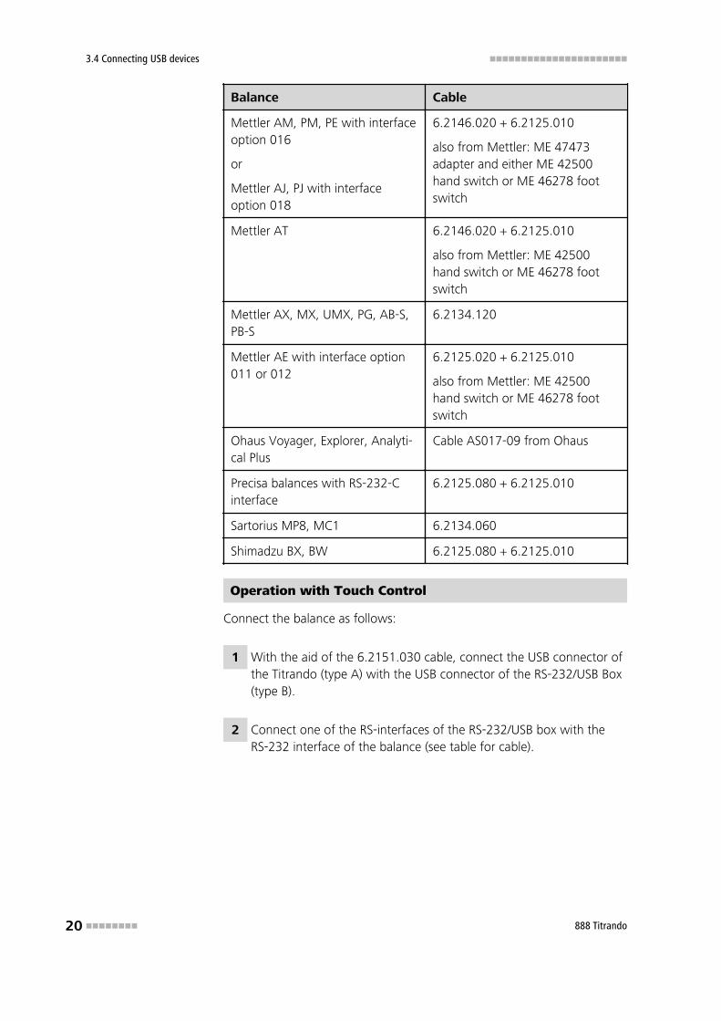
The following table offers an overview of the balances that you can usetogether with the Titrando system and of which cable you will need forconnection to the RS-232 interface:
Balance Cable
AND ER-60, 120, 180,182FR-200, 300FX 200, 300, 320with RS-232 interface (OP-03)
6.2125.020 + 6.2125.010
Mettler AB, AG, PR (LC-RS9) In the scope of delivery for thebalance
3.4 Connecting USB devices ■■■■■■■■■■■■■■■■■■■■■■
20 ■■■■■■■■ 888 Titrando
Balance Cable
Mettler AM, PM, PE with interfaceoption 016
or
Mettler AJ, PJ with interfaceoption 018
6.2146.020 + 6.2125.010
also from Mettler: ME 47473adapter and either ME 42500hand switch or ME 46278 footswitch
Mettler AT 6.2146.020 + 6.2125.010
also from Mettler: ME 42500hand switch or ME 46278 footswitch
Mettler AX, MX, UMX, PG, AB-S,PB-S
6.2134.120
Mettler AE with interface option011 or 012
6.2125.020 + 6.2125.010
also from Mettler: ME 42500hand switch or ME 46278 footswitch
Ohaus Voyager, Explorer, Analyti-cal Plus
Cable AS017-09 from Ohaus
Precisa balances with RS-232-Cinterface
6.2125.080 + 6.2125.010
Sartorius MP8, MC1 6.2134.060
Shimadzu BX, BW 6.2125.080 + 6.2125.010
Operation with Touch Control
Connect the balance as follows:
1 With the aid of the 6.2151.030 cable, connect the USB connector ofthe Titrando (type A) with the USB connector of the RS-232/USB Box(type B).
2 Connect one of the RS-interfaces of the RS-232/USB box with theRS-232 interface of the balance (see table for cable).
■■■■■■■■■■■■■■■■■■■■■■ 3 Installation
888 Titrando ■■■■■■■■ 21
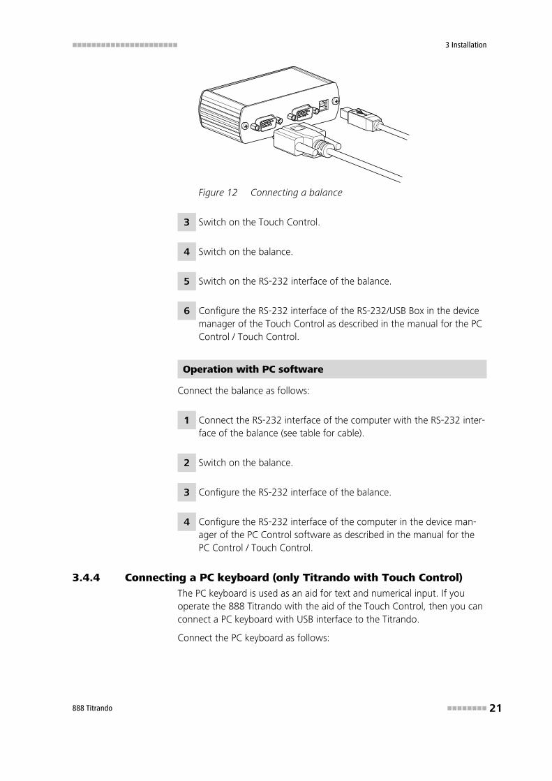
Figure 12 Connecting a balance
3 Switch on the Touch Control.
4 Switch on the balance.
5 Switch on the RS-232 interface of the balance.
6 Configure the RS-232 interface of the RS-232/USB Box in the devicemanager of the Touch Control as described in the manual for the PCControl / Touch Control.
Operation with PC software
Connect the balance as follows:
1 Connect the RS-232 interface of the computer with the RS-232 inter-face of the balance (see table for cable).
2 Switch on the balance.
3 Configure the RS-232 interface of the balance.
4 Configure the RS-232 interface of the computer in the device man-ager of the PC Control software as described in the manual for thePC Control / Touch Control.
3.4.4 Connecting a PC keyboard (only Titrando with Touch Control)The PC keyboard is used as an aid for text and numerical input. If youoperate the 888 Titrando with the aid of the Touch Control, then you canconnect a PC keyboard with USB interface to the Titrando.
Connect the PC keyboard as follows:
3.4 Connecting USB devices ■■■■■■■■■■■■■■■■■■■■■■
22 ■■■■■■■■ 888 Titrando
1 Insert the USB plug of the keyboard (type A) into one of the USBsockets of the Titrando.
2 Switch on the Touch Control.
The keyboard will be recognized automatically and entered in thedevice manager.
3 Configure the keyboard in the device manager of the Touch Controlas described in the manual for the PC Control / Touch Control.
3.4.5 Connecting a barcode readerThe barcode reader is used as an aid for text and numerical input. You canconnect a barcode reader with USB interface.
Operation with Touch Control
Connect the barcode reader as follows:
1 Insert the USB plug of the barcode reader (type A) into one of theUSB sockets of the Titrando.
2 Switch on the Touch Control.
The barcode reader will be recognized automatically and entered inthe device manager of the Touch Control.
3 Configure the barcode reader in the device manager as described inthe manual for the PC Control / Touch Control.
Operation with a PC software
Connect the barcode reader as follows:
1 Insert the USB plug of the barcode reader (type A) into one of theUSB sockets of the Titrando or the computer.
2 Start the PC software.
3 Configure the barcode reader in the device manager as described inthe manual for the PC Control / Touch Control.
■■■■■■■■■■■■■■■■■■■■■■ 3 Installation
888 Titrando ■■■■■■■■ 23
Settings on the barcode reader:
Program the barcode reader as follows (also see manual for the barcodereader).
1 Switch the barcode reader to programming mode.
2 Specify the desired layout for the keyboard (USA, Germany, France,Spain, German-speaking Switzerland).
This setting must match the setting in the device manager (see man-ual for PC Control / Touch Control).
3 Make sure that the barcode reader is set in such a way that Ctrl char-acters (ASCII 00 to 31) can be sent.
4 Program the barcode reader in such a way that the ASCII character02 (STX or Ctrl B) is sent as the first character. This first character isnormally referred to as the "Preamble" or "Prefix Code".
5 Program the barcode reader in such a way that the ASCII character04 (EOT or Ctrl D) is sent as the last character. This last character isnormally referred to as the "Postamble", "Record Suffix" or "PostfixCode".
6 Exit the programming mode.
3.4.6 Connecting a USB hubIf you wish to connect more than two devices to the USB connector of theTitrando, you can also use an additional commercially available USB hub(distributor). If you operate the Titrando with the aid of the Touch Control,then you should use a USB hub with its own power supply.
Connect the USB hub as follows:
1 Switch off the Touch Control and/or close the PC software.
2 With the aid of the 6.2151.020 cable, connect the USB connector ofthe Titrando (type A) with the USB connector of the hub (type B, seemanual for the hub).
3 Switch on the Touch Control, or start PC software respectively.
The USB hub is recognized automatically.
3.4 Connecting USB devices ■■■■■■■■■■■■■■■■■■■■■■
24 ■■■■■■■■ 888 Titrando
3.4.7 Connecting a Bluetooth® adapterPrinters and balances (or other devices with RS-232 connection) can beoptionally connected using a wireless Bluetooth® connection. Printers andbalance models with integrated Bluetooth® functionality are to be recom-mended for this purpose. Bluetooth® printer adapters for the USB inter-face can be obtained commercially, as can also Bluetooth® serial adaptersfor RS-232 connections (e.g. for balances).
Note
Bluetooth® is a registered and copyrighted name of the Bluetooth®
Special Interest Group (Bluetooth® SIG, Inc.).
PC Control
If the Titrando system is operated with the PC Control software, then aBluetooth USB adapter can be connected to one of the USB sockets onthe computer (or of the Titrando / USB Sample Processor). The driver soft-ware (for MS Windows 2000/XP) included in the scope of delivery by themanufacturer of the Bluetooth adapter must be installed in accordancewith the directions contained in the associated manual. A Bluetooth USBadapter must support the Bluetooth specifications HCRP (HardcopyCable Replacement Profile) for printers and/or SPP (Serial Port Pro-file) for balances or RS-232 connections. Printer drivers must be set upprior to the installation of the Bluetooth adapter.
840 Touch Control
If the Titrando system is operated as a stand-alone system with a 840Touch Control, then the Metrohm Bluetooth USB adapter for the840 (6.2162.000, Bluetooth® V1.1 qualified Class 2 device) is required fora Bluetooth connection.
Note
The Metrohm Bluetooth USB adapter cannot be operated on acomputer. The adapter is intended exclusively for use in a Titrando sys-tem in stand-alone operation, i.e. with a 840 Touch Control operatingunit as controller. The prerequisite is the Touch Control Software ver-sion 5.840.0130 or higher.
The Metrohm Bluetooth USB adapter permits wireless data transfer fordistances up to 10 m.
Install the Metrohm Bluetooth USB adapter as follows:
■■■■■■■■■■■■■■■■■■■■■■ 3 Installation
888 Titrando ■■■■■■■■ 25
1 Plug the Bluetooth adapter into an open USB interface on the rear ofthe Titrando.
2 Switch on the Touch Control.
The Bluetooth USB adapter is recognized automatically.
3 Configure the adapter in the device manager of the Touch Control asdescribed in the manual for the PC Control / Touch Control.
Printer and Bluetooth
A Bluetooth-compatible printer or a Bluetooth printer adapter must sup-port the HCRP (Hardcopy Cable Replacement Profile).
The necessary settings for a Bluetooth-compatible printer can be found inthe user manual for it. Bluetooth printer adapters can usually be connec-ted without configuration to the USB connector of the respective printer.Comply with the instructions contained in the documentation for theprinter adapter. Enter the definition of the printer type in the device man-ager of the Touch Control.
Balances and Bluetooth
A Bluetooth-compatible balance or a Bluetooth serial adapter must com-ply with the SPP (Serial Port Profile) in accordance to Bluetooth specifi-cations. If the balance manufacturer offers a specific Bluetooth serialadapter, then this is to be preferred to a commercially available adapter.
Bluetooth serial adapters must be configured on the PC with the help ofan auxiliary program supplied by the manufacturer. The data transferparameters of the instrument and the adapter must match one another.The Bluetooth serial adapter must be defined as the acceptor and not asthe initiator of a serial connection. Authentication with a PIN code is notsupported.
3.5 Connecting sensors ■■■■■■■■■■■■■■■■■■■■■■
26 ■■■■■■■■ 888 Titrando
3.5 Connecting sensors
3.5.1 GeneralThe measuring interface includes one high-ohm measuring input (Ind.),for a pH, redox or ISE electrode, one measuring input (Ref.) for a separatereference electrode, one measuring input (Temp.) for a temperature sen-sor, e.g. Pt 1000 or NTC, one measuring input (Pol.) for a polarizable elec-trode an one connection (iConnect) for an iConnect. It contains onemeasuring interface for electrodes with integrated data chip, referred toas iTodes.
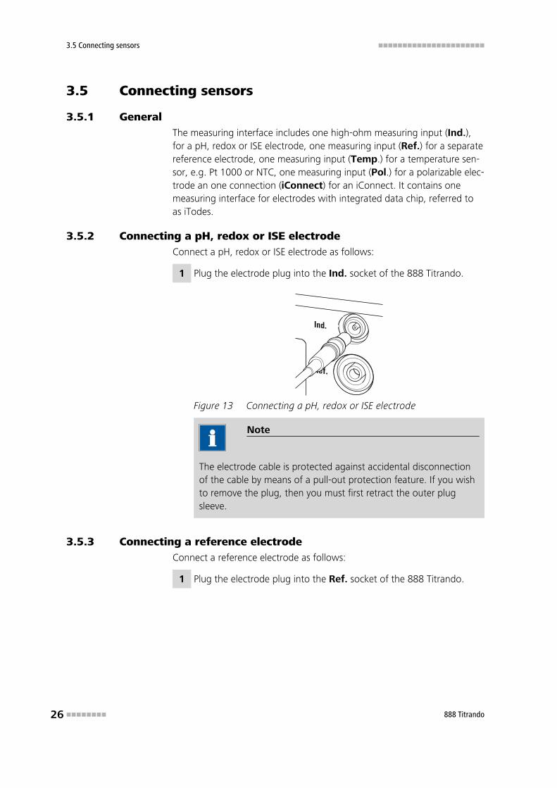
3.5.2 Connecting a pH, redox or ISE electrodeConnect a pH, redox or ISE electrode as follows:
1 Plug the electrode plug into the Ind. socket of the 888 Titrando.
Figure 13 Connecting a pH, redox or ISE electrode
Note
The electrode cable is protected against accidental disconnectionof the cable by means of a pull-out protection feature. If you wishto remove the plug, then you must first retract the outer plugsleeve.
3.5.3 Connecting a reference electrodeConnect a reference electrode as follows:
1 Plug the electrode plug into the Ref. socket of the 888 Titrando.
■■■■■■■■■■■■■■■■■■■■■■ 3 Installation
888 Titrando ■■■■■■■■ 27
Figure 14 Connecting a reference electrode
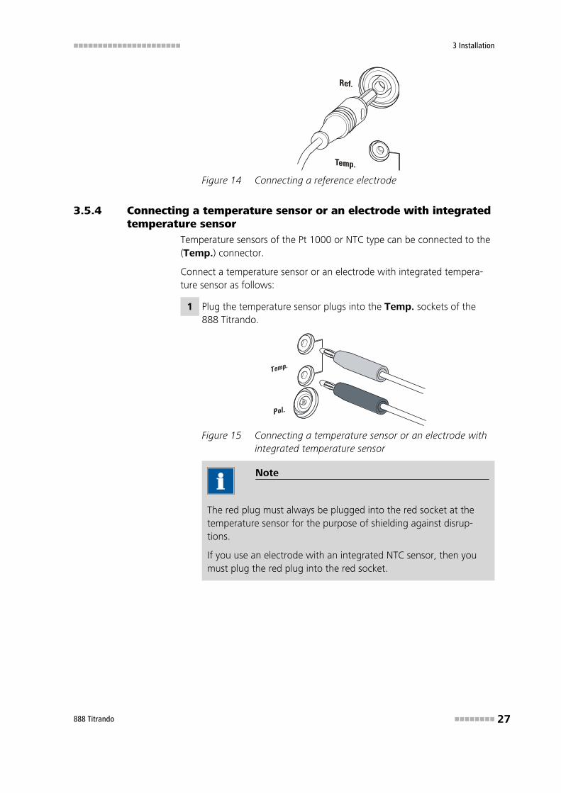
3.5.4 Connecting a temperature sensor or an electrode with integratedtemperature sensor
Temperature sensors of the Pt 1000 or NTC type can be connected to the(Temp.) connector.
Connect a temperature sensor or an electrode with integrated tempera-ture sensor as follows:
1 Plug the temperature sensor plugs into the Temp. sockets of the888 Titrando.
Figure 15 Connecting a temperature sensor or an electrode withintegrated temperature sensor
Note
The red plug must always be plugged into the red socket at thetemperature sensor for the purpose of shielding against disrup-tions.
If you use an electrode with an integrated NTC sensor, then youmust plug the red plug into the red socket.
3.5 Connecting sensors ■■■■■■■■■■■■■■■■■■■■■■
28 ■■■■■■■■ 888 Titrando
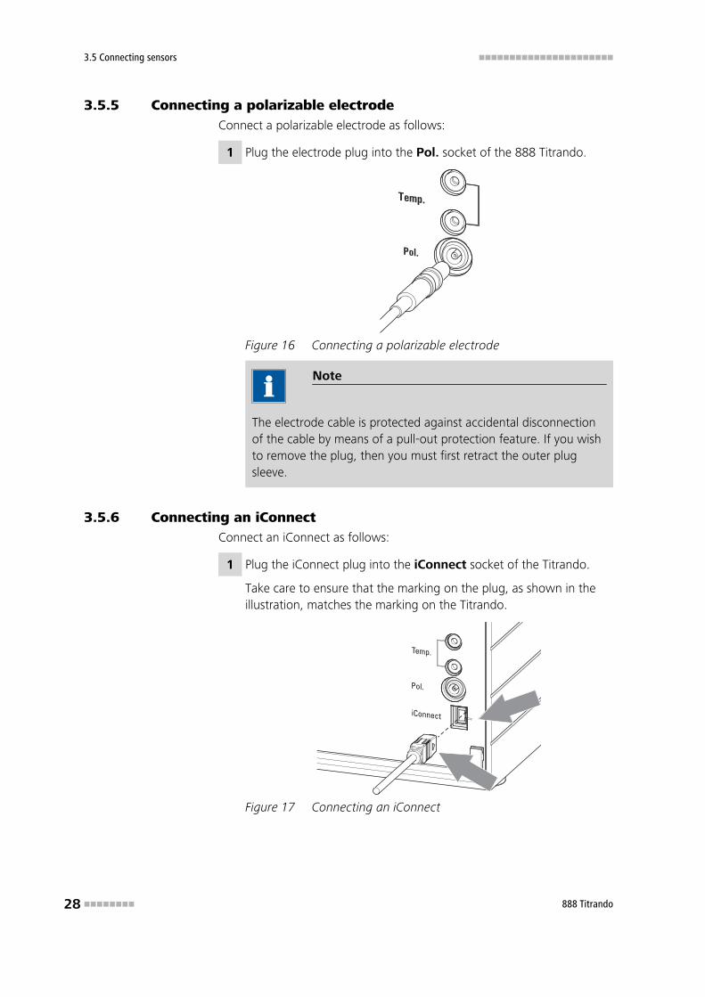
3.5.5 Connecting a polarizable electrodeConnect a polarizable electrode as follows:
1 Plug the electrode plug into the Pol. socket of the 888 Titrando.
Figure 16 Connecting a polarizable electrode
Note
The electrode cable is protected against accidental disconnectionof the cable by means of a pull-out protection feature. If you wishto remove the plug, then you must first retract the outer plugsleeve.
3.5.6 Connecting an iConnectConnect an iConnect as follows:
1 Plug the iConnect plug into the iConnect socket of the Titrando.
Take care to ensure that the marking on the plug, as shown in theillustration, matches the marking on the Titrando.
Figure 17 Connecting an iConnect
■■■■■■■■■■■■■■■■■■■■■■ 3 Installation
888 Titrando ■■■■■■■■ 29
The iConnect is detected automatically and entered into the deviceproperties of the Titrando as measuring input. If an electrode is con-nected to the iConnect that is not yet included in the list of sensorsfor the control software, then a corresponding message will be dis-played.
The iConnect can be plugged in and unplugged while the Titrando isswitched on.
An electrode with integrated data chip, referred to as iTrode, is connectedto the iConnect.
Connect the electrode as follows:
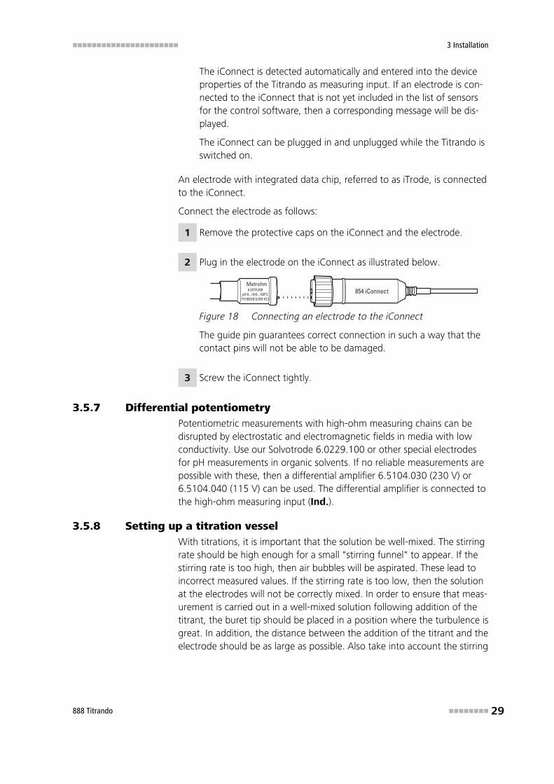
1 Remove the protective caps on the iConnect and the electrode.
2 Plug in the electrode on the iConnect as illustrated below.
Figure 18 Connecting an electrode to the iConnect
The guide pin guarantees correct connection in such a way that thecontact pins will not be able to be damaged.
3 Screw the iConnect tightly.
3.5.7 Differential potentiometryPotentiometric measurements with high-ohm measuring chains can bedisrupted by electrostatic and electromagnetic fields in media with lowconductivity. Use our Solvotrode 6.0229.100 or other special electrodesfor pH measurements in organic solvents. If no reliable measurements arepossible with these, then a differential amplifier 6.5104.030 (230 V) or6.5104.040 (115 V) can be used. The differential amplifier is connected tothe high-ohm measuring input (Ind.).
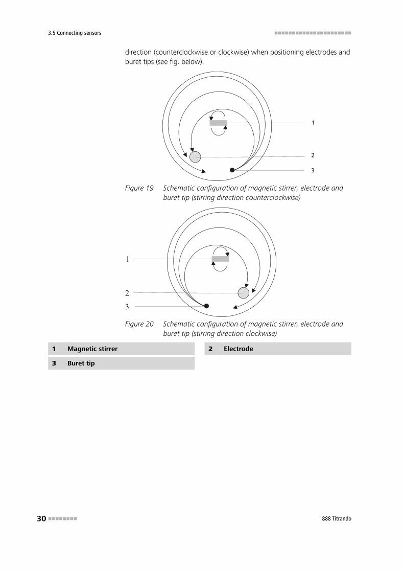
3.5.8 Setting up a titration vesselWith titrations, it is important that the solution be well-mixed. The stirringrate should be high enough for a small "stirring funnel" to appear. If thestirring rate is too high, then air bubbles will be aspirated. These lead toincorrect measured values. If the stirring rate is too low, then the solutionat the electrodes will not be correctly mixed. In order to ensure that meas-urement is carried out in a well-mixed solution following addition of thetitrant, the buret tip should be placed in a position where the turbulence isgreat. In addition, the distance between the addition of the titrant and theelectrode should be as large as possible. Also take into account the stirring
3.5 Connecting sensors ■■■■■■■■■■■■■■■■■■■■■■
30 ■■■■■■■■ 888 Titrando
direction (counterclockwise or clockwise) when positioning electrodes andburet tips (see fig. below).
Figure 19 Schematic configuration of magnetic stirrer, electrode andburet tip (stirring direction counterclockwise)
1
2
3
Figure 20 Schematic configuration of magnetic stirrer, electrode andburet tip (stirring direction clockwise)
1 Magnetic stirrer 2 Electrode
3 Buret tip
■■■■■■■■■■■■■■■■■■■■■■ 4 Working with the exchange unit
888 Titrando ■■■■■■■■ 31
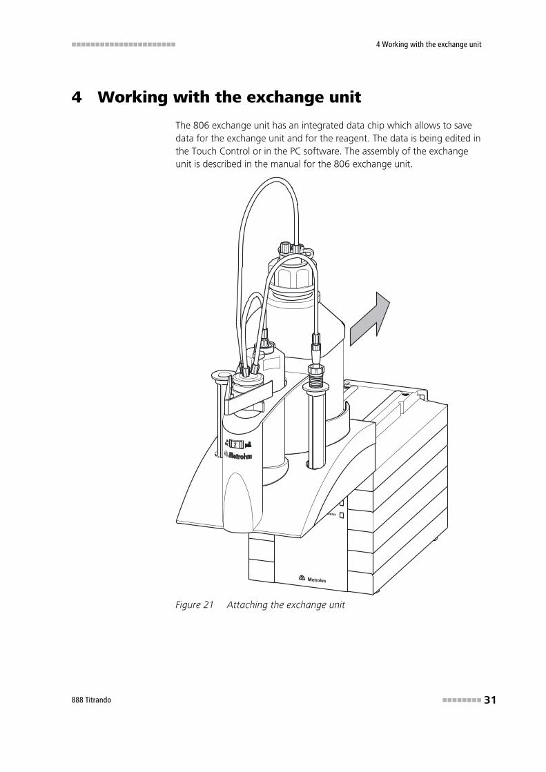
4 Working with the exchange unit
The 806 exchange unit has an integrated data chip which allows to savedata for the exchange unit and for the reagent. The data is being edited inthe Touch Control or in the PC software. The assembly of the exchangeunit is described in the manual for the 806 exchange unit.
Figure 21 Attaching the exchange unit
■■■■■■■■■■■■■■■■■■■■■■
32 ■■■■■■■■ 888 Titrando
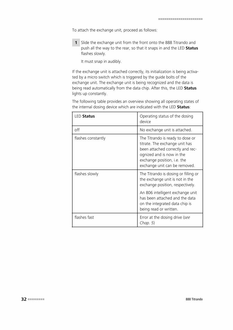
To attach the exchange unit, proceed as follows:
1 Slide the exchange unit from the front onto the 888 Titrando andpush all the way to the rear, so that it snaps in and the LED Statusflashes slowly.
It must snap in audibly.
If the exchange unit is attached correctly, its initialization is being activa-ted by a micro switch which is triggered by the guide bolts of theexchange unit. The exchange unit is being recognized and the data isbeing read automatically from the data chip. After this, the LED Statuslights up constantly.
The following table provides an overview showing all operating states ofthe internal dosing device which are indicated with the LED Status:
LED Status Operating status of the dosingdevice
off No exchange unit is attached.
flashes constantly The Titrando is ready to dose ortitrate. The exchange unit hasbeen attached correctly and rec-ognized and is now in theexchange position, i.e. theexchange unit can be removed.
flashes slowly The Titrando is dosing or filling orthe exchange unit is not in theexchange position, respectively.
An 806 intelligent exchange unithas been attached and the dataon the integrated data chip isbeing read or written.
flashes fast Error at the dosing drive (seeChap. 5)
■■■■■■■■■■■■■■■■■■■■■■ 5 Handling and maintenance
888 Titrando ■■■■■■■■ 33
5 Handling and maintenance
5.1 General information
5.1.1 CareThe 888 Titrando requires appropriate care. Excess contamination of theinstrument may result in functional disruptions and a reduction in the serv-ice life of the sturdy mechanics and electronics.
Spilled chemicals and solvents must be removed immediately. Above all,the plug connections on the rear of the instrument (in particular the mainsconnection socket) should be protected from contamination.
Caution
Although this is extensively prevented by design measures, the mainsplug should be unplugged immediately if aggressive media has penetra-ted the inside of the instrument, so as to avoid serious damage to theinstrument electronics. In such cases, the Metrohm Service must beinformed.
5.1.2 Maintenance by Metrohm ServiceMaintenance of the 888 Titrando is best carried out as part of an annualservice, which is performed by technicians of the Metrohm company. Ifworking frequently with caustic and corrosive chemicals, a shorter mainte-nance interval could be necessary.
The Metrohm service department offers every form of technical advice formaintenance and service of all Metrohm instruments.
5.2 Quality Management and validation with Metrohm ■■■■■■■■■■■■■■■■■■■■■■
34 ■■■■■■■■ 888 Titrando
5.2 Quality Management and validation with Metrohm
Quality Management
Metrohm offers you comprehensive support in implementing quality man-agement measures for instruments and software. Further information onthis can be found in the brochure «Quality Management withMetrohm» available from your local Metrohm agent.
Validation
Please contact your local Metrohm agent for support in validating instru-ments and software. Here you can also obtain validation documentationto provide help for carrying out the Installation Qualification (IQ) andthe Operational Qualification (OQ). IQ and OQ are also offered as aservice by the Metrohm agents. In addition, various application bulletinsare also available on the subject, which also contain Standard Operat-ing Procedures (SOP) for testing analytical measuring instruments forreproducibility and correctness.
Maintenance
Electronic and mechanical functional groups in Metrohm instruments canand should be checked as part of regular maintenance by specialist per-sonnel from Metrohm. Please ask your local Metrohm agent regarding theprecise terms and conditions involved in concluding a correspondingmaintenance agreement.
Note
You can find information on the subjects of quality management, vali-dation and maintenance as well as an overview of the documents cur-rently available at www.metrohm.com/com/ under Support.
■■■■■■■■■■■■■■■■■■■■■■ 6 Troubleshooting
888 Titrando ■■■■■■■■ 35
6 Troubleshooting
6.1 Problems
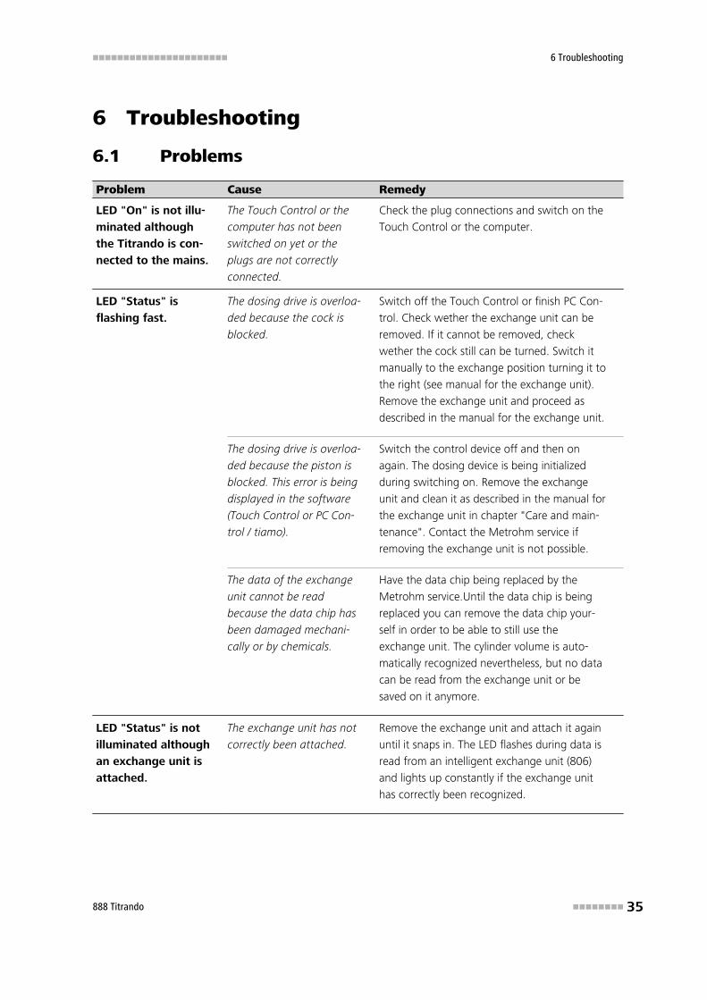
Problem Cause Remedy
LED "On" is not illu-
minated although
the Titrando is con-
nected to the mains.
The Touch Control or the
computer has not been
switched on yet or the
plugs are not correctly
connected.
Check the plug connections and switch on the
Touch Control or the computer.
LED "Status" is
flashing fast.
The dosing drive is overloa-
ded because the cock is
blocked.
Switch off the Touch Control or finish PC Con-
trol. Check wether the exchange unit can be
removed. If it cannot be removed, check
wether the cock still can be turned. Switch it
manually to the exchange position turning it to
the right (see manual for the exchange unit).
Remove the exchange unit and proceed as
described in the manual for the exchange unit.
The dosing drive is overloa-
ded because the piston is
blocked. This error is being
displayed in the software
(Touch Control or PC Con-
trol / tiamo).
Switch the control device off and then on
again. The dosing device is being initialized
during switching on. Remove the exchange
unit and clean it as described in the manual for
the exchange unit in chapter "Care and main-
tenance". Contact the Metrohm service if
removing the exchange unit is not possible.
The data of the exchange
unit cannot be read
because the data chip has
been damaged mechani-
cally or by chemicals.
Have the data chip being replaced by the
Metrohm service.Until the data chip is being
replaced you can remove the data chip your-
self in order to be able to still use the
exchange unit. The cylinder volume is auto-
matically recognized nevertheless, but no data
can be read from the exchange unit or be
saved on it anymore.
LED "Status" is not
illuminated although
an exchange unit is
attached.
The exchange unit has not
correctly been attached.
Remove the exchange unit and attach it again
until it snaps in. The LED flashes during data is
read from an intelligent exchange unit (806)
and lights up constantly if the exchange unit
has correctly been recognized.
6.1 Problems ■■■■■■■■■■■■■■■■■■■■■■
36 ■■■■■■■■ 888 Titrando
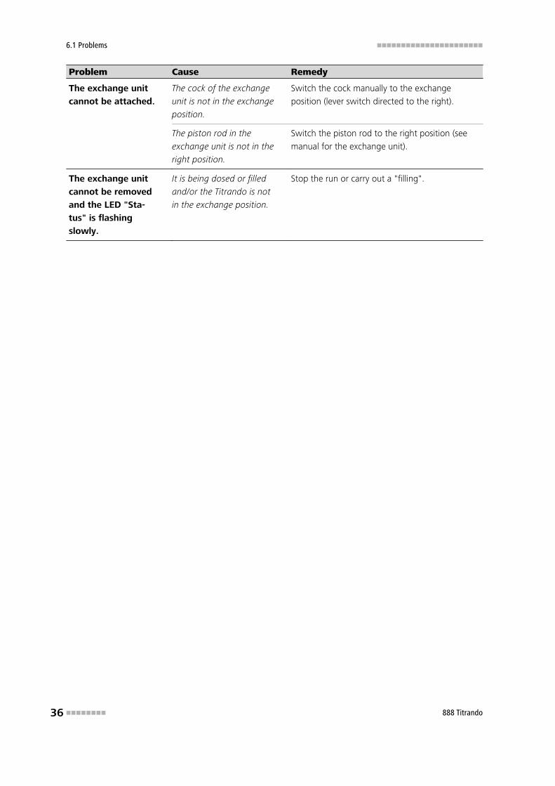
Problem Cause Remedy
The exchange unit
cannot be attached.
The cock of the exchange
unit is not in the exchange
position.
Switch the cock manually to the exchange
position (lever switch directed to the right).
The piston rod in the
exchange unit is not in the
right position.
Switch the piston rod to the right position (see
manual for the exchange unit).
The exchange unit
cannot be removed
and the LED "Sta-
tus" is flashing
slowly.
It is being dosed or filled
and/or the Titrando is not
in the exchange position.
Stop the run or carry out a "filling".
■■■■■■■■■■■■■■■■■■■■■■ 7 Appendix
888 Titrando ■■■■■■■■ 37
7 Appendix
7.1 Remote interface
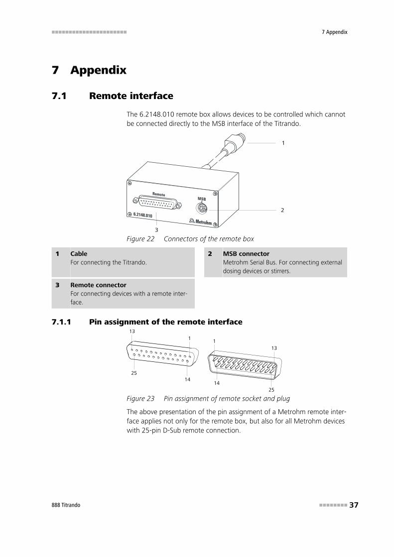
The 6.2148.010 remote box allows devices to be controlled which cannotbe connected directly to the MSB interface of the Titrando.
1
2
3
Figure 22 Connectors of the remote box
1 CableFor connecting the Titrando.
2 MSB connectorMetrohm Serial Bus. For connecting externaldosing devices or stirrers.
3 Remote connectorFor connecting devices with a remote inter-face.
7.1.1 Pin assignment of the remote interface13
1
1425
113
1425
Figure 23 Pin assignment of remote socket and plug
The above presentation of the pin assignment of a Metrohm remote inter-face applies not only for the remote box, but also for all Metrohm deviceswith 25-pin D-Sub remote connection.
7.1 Remote interface ■■■■■■■■■■■■■■■■■■■■■■
38 ■■■■■■■■ 888 Titrando
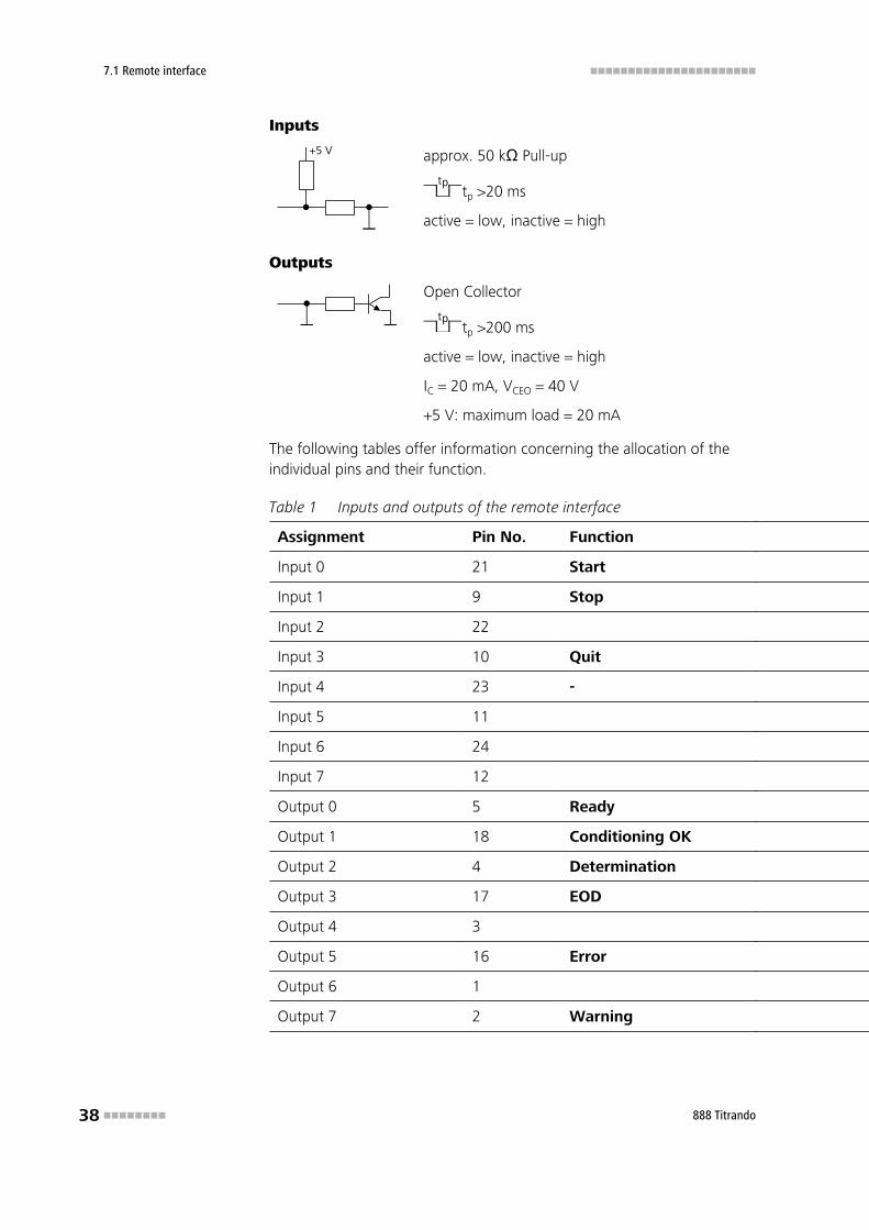
Inputs
+5 V approx. 50 kΩ Pull-up
tptp >20 ms
active = low, inactive = high
Outputs
Open Collector
tptp >200 ms
active = low, inactive = high
IC = 20 mA, VCEO = 40 V
+5 V: maximum load = 20 mA
The following tables offer information concerning the allocation of theindividual pins and their function.
Table 1 Inputs and outputs of the remote interface
Assignment Pin No. Function
Input 0 21 Start
Input 1 9 Stop
Input 2 22
Input 3 10 Quit
Input 4 23 -
Input 5 11
Input 6 24
Input 7 12
Output 0 5 Ready
Output 1 18 Conditioning OK
Output 2 4 Determination
Output 3 17 EOD
Output 4 3
Output 5 16 Error
Output 6 1
Output 7 2 Warning
■■■■■■■■■■■■■■■■■■■■■■ 7 Appendix
888 Titrando ■■■■■■■■ 39
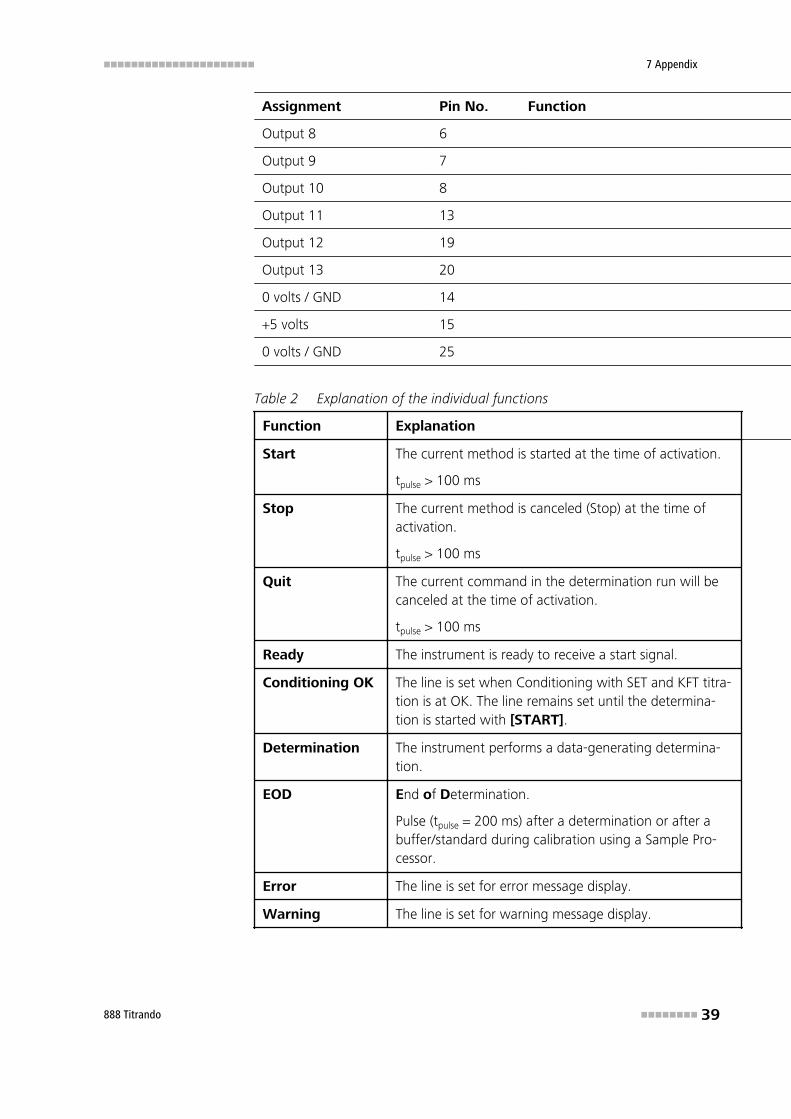
Assignment Pin No. Function
Output 8 6
Output 9 7
Output 10 8
Output 11 13
Output 12 19
Output 13 20
0 volts / GND 14
+5 volts 15
0 volts / GND 25
Table 2 Explanation of the individual functions
Function Explanation
Start The current method is started at the time of activation.
tpulse > 100 ms
Stop The current method is canceled (Stop) at the time ofactivation.
tpulse > 100 ms
Quit The current command in the determination run will becanceled at the time of activation.
tpulse > 100 ms
Ready The instrument is ready to receive a start signal.
Conditioning OK The line is set when Conditioning with SET and KFT titra-tion is at OK. The line remains set until the determina-tion is started with [START].
Determination The instrument performs a data-generating determina-tion.
EOD End of Determination.
Pulse (tpulse = 200 ms) after a determination or after abuffer/standard during calibration using a Sample Pro-cessor.
Error The line is set for error message display.
Warning The line is set for warning message display.
8.1 Measuring interface ■■■■■■■■■■■■■■■■■■■■■■
40 ■■■■■■■■ 888 Titrando
8 Technical data
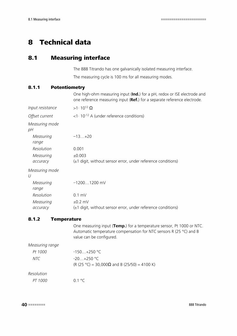
8.1 Measuring interface
The 888 Titrando has one galvanically isolated measuring interface.
The measuring cycle is 100 ms for all measuring modes.
8.1.1 PotentiometryOne high-ohm measuring input (Ind.) for a pH, redox or ISE electrode andone reference measuring input (Ref.) for a separate reference electrode.
Input resistance >1· 1012 Ω
Offset current <1· 10-12 A (under reference conditions)
Measuring modepH
Measuringrange
–13…+20
Resolution 0.001
Measuringaccuracy
±0.003(±1 digit, without sensor error, under reference conditions)
Measuring modeU
Measuringrange
–1200…1200 mV
Resolution 0.1 mV
Measuringaccuracy
±0.2 mV(±1 digit, without sensor error, under reference conditions)
8.1.2 TemperatureOne measuring input (Temp.) for a temperature sensor, Pt 1000 or NTC.Automatic temperature compensation for NTC sensors R (25 °C) and Bvalue can be configured.
Measuring range
Pt 1000 -150…+250 °C
NTC -20…+250 °C(R (25 °C) = 30,000Ω and B (25/50) = 4100 K)
Resolution
PT 1000 0.1 °C
■■■■■■■■■■■■■■■■■■■■■■ 8 Technical data
888 Titrando ■■■■■■■■ 41
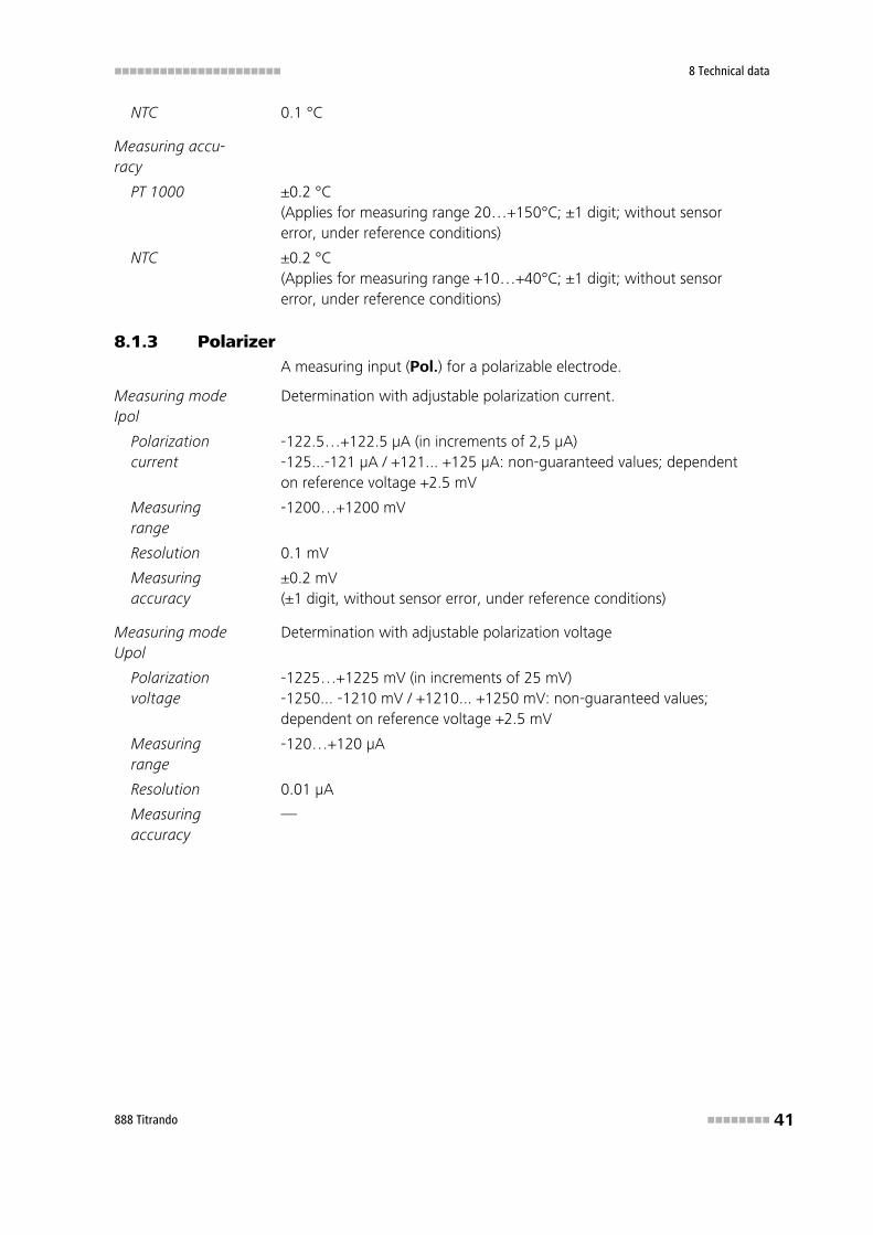
NTC 0.1 °C
Measuring accu-racy
PT 1000 ±0.2 °C(Applies for measuring range 20…+150°C; ±1 digit; without sensorerror, under reference conditions)
NTC ±0.2 °C(Applies for measuring range +10…+40°C; ±1 digit; without sensorerror, under reference conditions)
8.1.3 PolarizerA measuring input (Pol.) for a polarizable electrode.
Measuring modeIpol
Determination with adjustable polarization current.
Polarizationcurrent
-122.5…+122.5 µA (in increments of 2,5 µA)-125...-121 µA / +121... +125 µA: non-guaranteed values; dependenton reference voltage +2.5 mV
Measuringrange
-1200…+1200 mV
Resolution 0.1 mV
Measuringaccuracy
±0.2 mV(±1 digit, without sensor error, under reference conditions)
Measuring modeUpol
Determination with adjustable polarization voltage
Polarizationvoltage
-1225…+1225 mV (in increments of 25 mV)-1250... -1210 mV / +1210... +1250 mV: non-guaranteed values;dependent on reference voltage +2.5 mV
Measuringrange
-120…+120 µA
Resolution 0.01 µA
Measuringaccuracy
—
8.2 Internal dosing device ■■■■■■■■■■■■■■■■■■■■■■
42 ■■■■■■■■ 888 Titrando
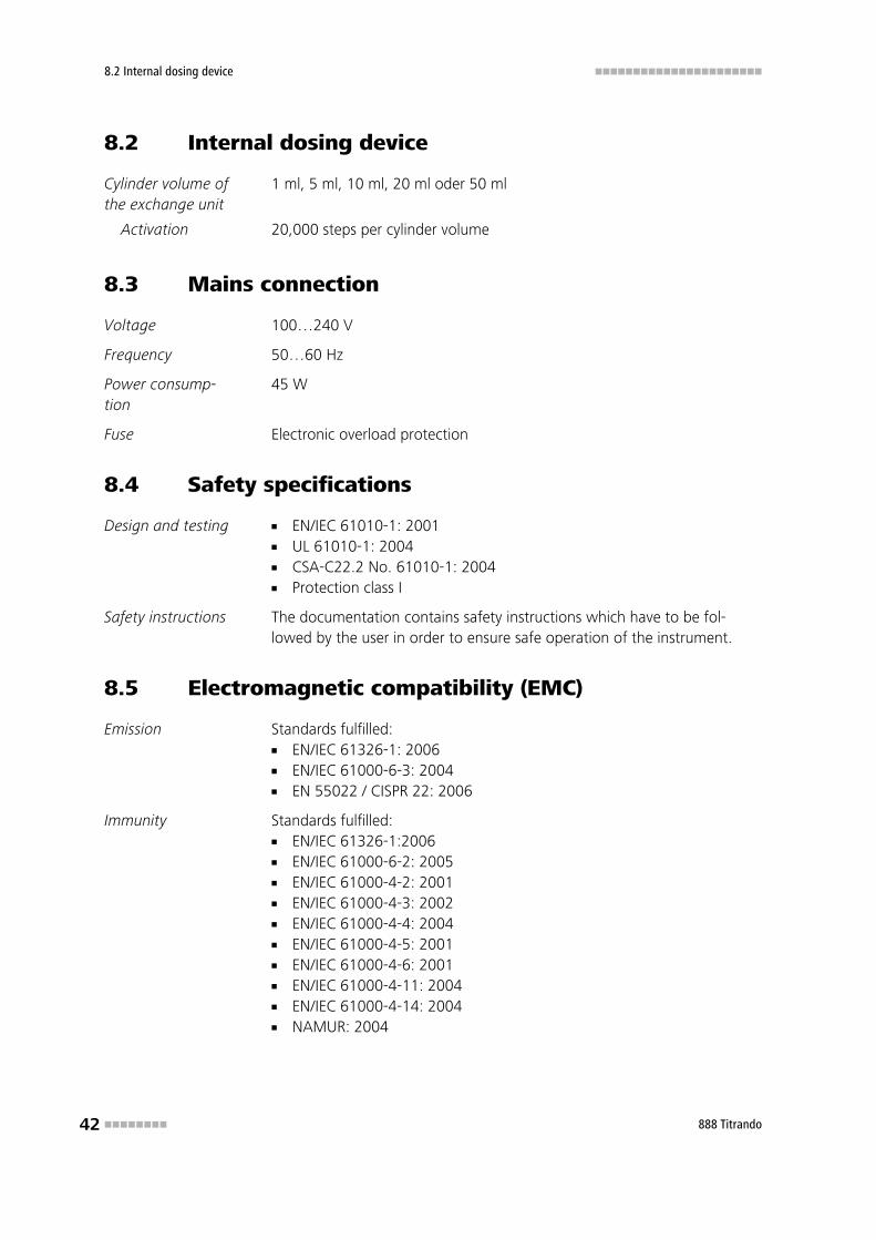
8.2 Internal dosing device
Cylinder volume ofthe exchange unit
1 ml, 5 ml, 10 ml, 20 ml oder 50 ml
Activation 20,000 steps per cylinder volume
8.3 Mains connection
Voltage 100…240 V
Frequency 50…60 Hz
Power consump-tion
45 W
Fuse Electronic overload protection
8.4 Safety specifications
Design and testing ■ EN/IEC 61010-1: 2001■ UL 61010-1: 2004■ CSA-C22.2 No. 61010-1: 2004■ Protection class I
Safety instructions The documentation contains safety instructions which have to be fol-lowed by the user in order to ensure safe operation of the instrument.
8.5 Electromagnetic compatibility (EMC)
Emission Standards fulfilled:■ EN/IEC 61326-1: 2006■ EN/IEC 61000-6-3: 2004■ EN 55022 / CISPR 22: 2006
Immunity Standards fulfilled:■ EN/IEC 61326-1:2006■ EN/IEC 61000-6-2: 2005■ EN/IEC 61000-4-2: 2001■ EN/IEC 61000-4-3: 2002■ EN/IEC 61000-4-4: 2004■ EN/IEC 61000-4-5: 2001■ EN/IEC 61000-4-6: 2001■ EN/IEC 61000-4-11: 2004■ EN/IEC 61000-4-14: 2004■ NAMUR: 2004
■■■■■■■■■■■■■■■■■■■■■■ 8 Technical data
888 Titrando ■■■■■■■■ 43
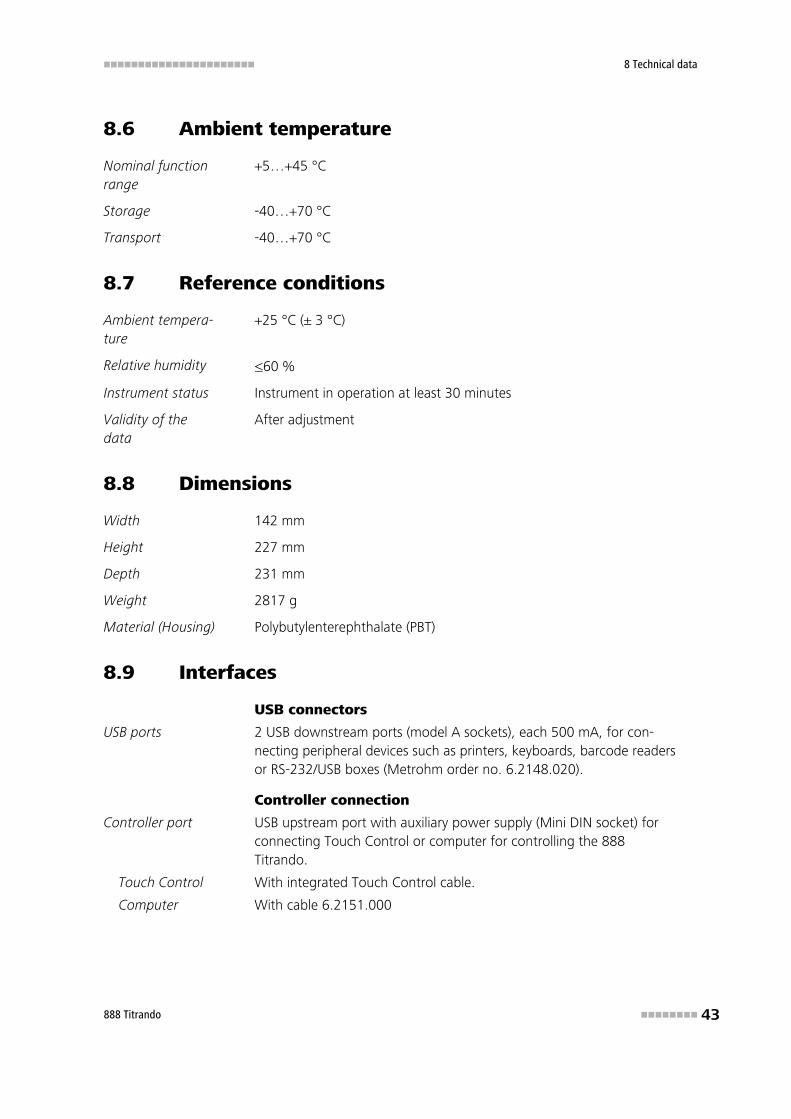
8.6 Ambient temperature
Nominal functionrange
+5…+45 °C
Storage -40…+70 °C
Transport -40…+70 °C
8.7 Reference conditions
Ambient tempera-ture
+25 °C (± 3 °C)
Relative humidity ≤60 %
Instrument status Instrument in operation at least 30 minutes
Validity of thedata
After adjustment
8.8 Dimensions
Width 142 mm
Height 227 mm
Depth 231 mm
Weight 2817 g
Material (Housing) Polybutylenterephthalate (PBT)
8.9 Interfaces
USB connectors
USB ports 2 USB downstream ports (model A sockets), each 500 mA, for con-necting peripheral devices such as printers, keyboards, barcode readersor RS-232/USB boxes (Metrohm order no. 6.2148.020).
Controller connection
Controller port USB upstream port with auxiliary power supply (Mini DIN socket) forconnecting Touch Control or computer for controlling the 888Titrando.
Touch Control With integrated Touch Control cable.
Computer With cable 6.2151.000
8.9 Interfaces ■■■■■■■■■■■■■■■■■■■■■■
44 ■■■■■■■■ 888 Titrando
MSB connectors (Metrohm Serial Bus)
Dosing device Connection for a maximum of 3 external dosing devices, models Dosi-mat or Dosino (MSB 2 to MSB 4).
Stirrer Connection for a maximum of 4 stirrers.Stirrer control: manual On/Off switching or coordination with the titra-tion sequence.Rate in 15 stages and shift direction can be selected.
Remote box Connection for a maximum of four remote boxes. Remote boxes canbe used to actuate and monitor external devices.
■■■■■■■■■■■■■■■■■■■■■■ 9 Conformity and warranty
888 Titrando ■■■■■■■■ 45
9 Conformity and warranty
9.1 Declaration of Conformity
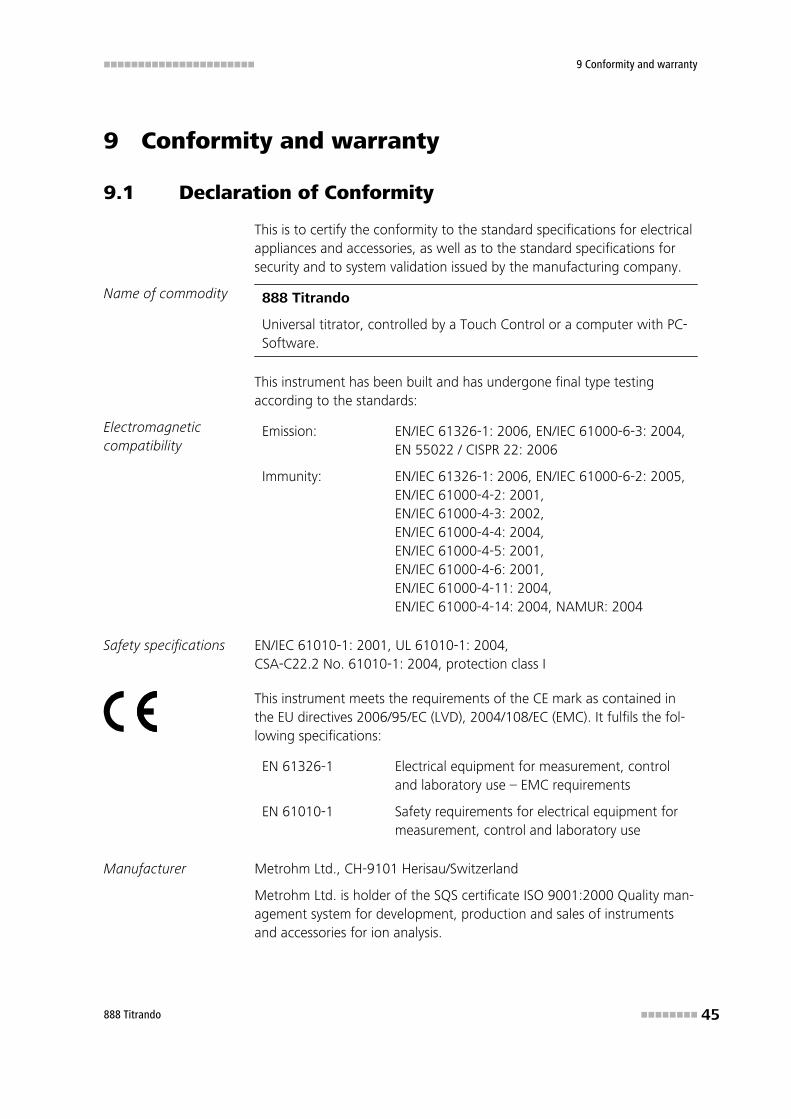
This is to certify the conformity to the standard specifications for electricalappliances and accessories, as well as to the standard specifications forsecurity and to system validation issued by the manufacturing company.
Name of commodity 888 Titrando
Universal titrator, controlled by a Touch Control or a computer with PC-Software.
This instrument has been built and has undergone final type testingaccording to the standards:
Electromagneticcompatibility
Emission: EN/IEC 61326-1: 2006, EN/IEC 61000-6-3: 2004,EN 55022 / CISPR 22: 2006
Immunity: EN/IEC 61326-1: 2006, EN/IEC 61000-6-2: 2005,EN/IEC 61000-4-2: 2001,EN/IEC 61000-4-3: 2002,EN/IEC 61000-4-4: 2004,EN/IEC 61000-4-5: 2001,EN/IEC 61000-4-6: 2001,EN/IEC 61000-4-11: 2004,EN/IEC 61000-4-14: 2004, NAMUR: 2004
Safety specifications EN/IEC 61010-1: 2001, UL 61010-1: 2004,CSA-C22.2 No. 61010-1: 2004, protection class I
This instrument meets the requirements of the CE mark as contained inthe EU directives 2006/95/EC (LVD), 2004/108/EC (EMC). It fulfils the fol-lowing specifications:
EN 61326-1 Electrical equipment for measurement, controland laboratory use – EMC requirements
EN 61010-1 Safety requirements for electrical equipment formeasurement, control and laboratory use
Manufacturer Metrohm Ltd., CH-9101 Herisau/Switzerland
Metrohm Ltd. is holder of the SQS certificate ISO 9001:2000 Quality man-agement system for development, production and sales of instrumentsand accessories for ion analysis.

9.2 Quality Management Principles ■■■■■■■■■■■■■■■■■■■■■■
46 ■■■■■■■■ 888 Titrando
Herisau, 10 January, 2008
D. Strohm
Vice President, Head of R&D
Ch. Buchmann
Vice President, Head of Production
Responsible for Quality Assurance
9.2 Quality Management Principles
Metrohm Ltd. holds the ISO 9001:2000 Certificate, registration number10872-02, issued by SQS (Swiss Association for Quality and ManagementSystems). Internal and external audits are carried out periodically to assurethat the standards defined by Metrohm’s QM Manual are maintained.
The steps involved in the design, manufacture and servicing of instrumentsare fully documented and the resulting reports are archived for ten years.The development of software for PCs and instruments is also duly docu-mented and the documents and source codes are archived. Both remainthe possession of Metrohm. A non-disclosure agreement may be asked tobe provided by those requiring access to them.
The implementation of the ISO 9001:2000 quality management system isdescribed in Metrohm’s QM Manual, which comprises detailed instruc-tions on the following fields of activity:
Instrument development
The organization of the instrument design, its planning and the intermedi-ate controls are fully documented and traceable. Laboratory testingaccompanies all phases of instrument development.
Software development
Software development occurs in terms of the software life cycle. Tests areperformed to detect programming errors and to assess the program’sfunctionality in a laboratory environment.
Components
All components used in the Metrohm instruments have to satisfy the qual-ity standards that are defined and implemented for our products. Suppli-ers of components are audited by Metrohm as the need arises.
Manufacture
The measures put into practice in the production of our instruments guar-antee a constant quality standard. Production planning and manufacturing

■■■■■■■■■■■■■■■■■■■■■■ 9 Conformity and warranty
888 Titrando ■■■■■■■■ 47
procedures, maintenance of production means and testing of compo-nents, intermediate and finished products are prescribed.
Customer support and service
Customer support involves all phases of instrument acquisition and use bythe customer, i.e. consulting to define the adequate equipment for theanalytical problem at hand, delivery of the equipment, user manuals, train-ing, after-sales service and processing of customer complaints. TheMetrohm service organization is equipped to support customers in imple-menting standards such as GLP, GMP, ISO 900X, in performing Opera-tional Qualification and Performance Verification of the system compo-nents or in carrying out the System Validation for the quantitative determi-nation of a substance in a given matrix.
9.3 Warranty (guarantee)
Metrohm guarantees that the deliveries and services it provides are freefrom material, design or manufacturing errors. The warranty period is 36months from the day of delivery; for day and night operation it is 18months. The warranty remains valid on condition that the service is provi-ded by an authorized Metrohm service organization.
Glass breakage is excluded from the warranty for electrodes and otherglassware. The warranty for the accuracy corresponds to the technicalspecifications given in this manual. For components from third parties thatmake up a considerable part of our instrument, the manufacturer's war-ranty provisions apply. Warranty claims cannot be pursued if the Customerhas not complied with the obligations to make payment on time.
During the warranty period Metrohm undertakes, at its own choice, toeither repair at its own premises, free of charge, any instruments that canbe shown to be faulty or to replace them. Transport costs are to the Cus-tomer's account.
Faults arising from circumstances that are not the responsibility ofMetrohm, such as improper storage or improper use, etc. are expresslyexcluded from the warranty.
10.1 Scope of delivery ■■■■■■■■■■■■■■■■■■■■■■
48 ■■■■■■■■ 888 Titrando
10 Accessories
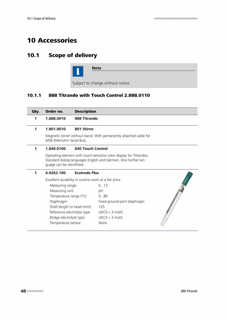
10.1 Scope of delivery
Note
Subject to change without notice.
10.1.1 888 Titrando with Touch Control 2.888.0110
Qty. Order no. Description
1 1.888.0010 888 Titrando
1 1.801.0010 801 Stirrer
Magnetic stirrer without stand. With pemanently attached cable forMSB (Metrohm Serial Bus).
1 1.840.0100 840 Touch Control
Operating element with touch-sensitive color display for Titrandos.Standard dialog languages English and German. One further lan-guage can be retrofitted.
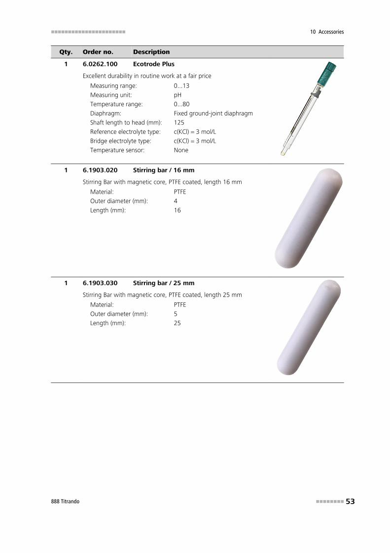
1 6.0262.100 Ecotrode Plus
Excellent durability in routine work at a fair price
Measuring range: 0...13
Measuring unit: pH
Temperature range (°C): 0...80
Diaphragm: Fixed ground-joint diaphragm
Shaft length to head (mm): 125
Reference electrolyte type: c(KCl) = 3 mol/L
Bridge electrolyte type: c(KCl) = 3 mol/L
Temperature sensor: None
■■■■■■■■■■■■■■■■■■■■■■ 10 Accessories
888 Titrando ■■■■■■■■ 49
Qty. Order no. Description
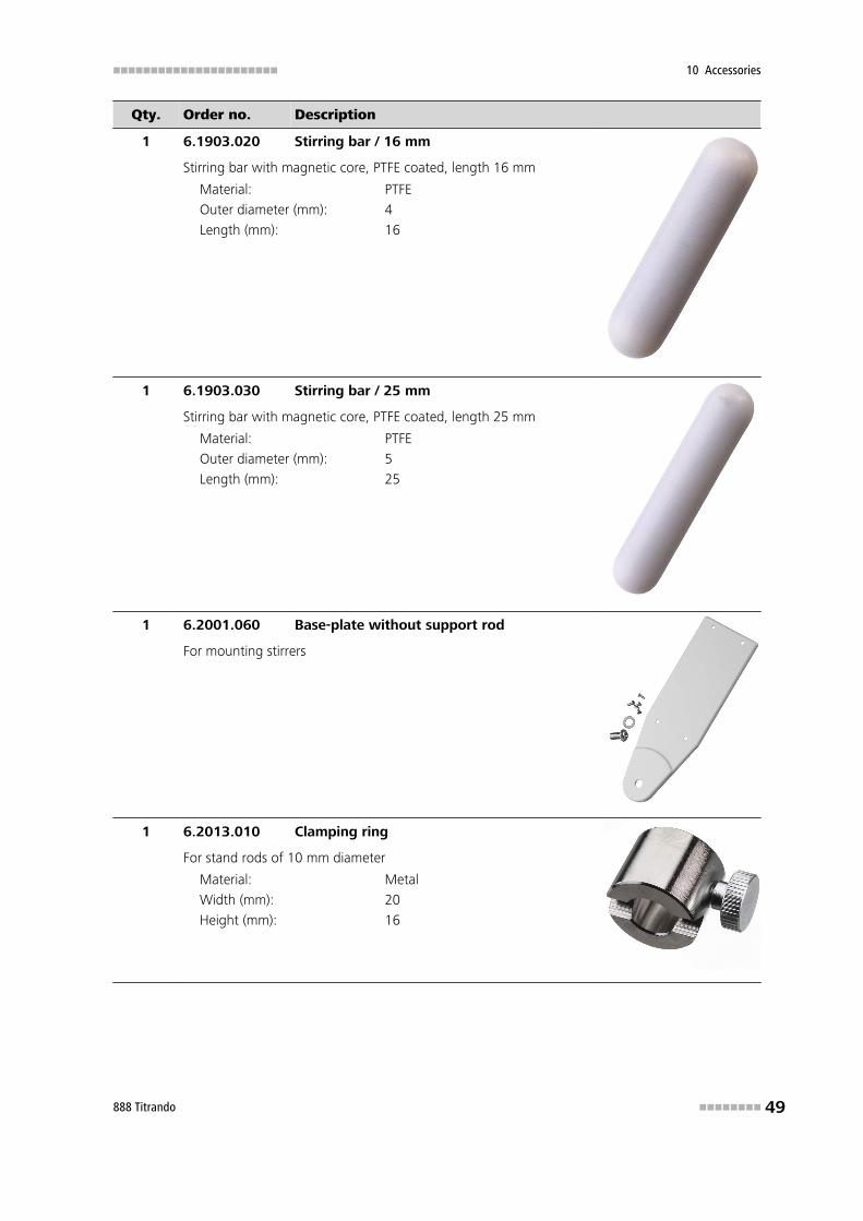
1 6.1903.020 Stirring bar / 16 mm
Stirring bar with magnetic core, PTFE coated, length 16 mm
Material: PTFE
Outer diameter (mm): 4
Length (mm): 16
1 6.1903.030 Stirring bar / 25 mm
Stirring bar with magnetic core, PTFE coated, length 25 mm
Material: PTFE
Outer diameter (mm): 5
Length (mm): 25
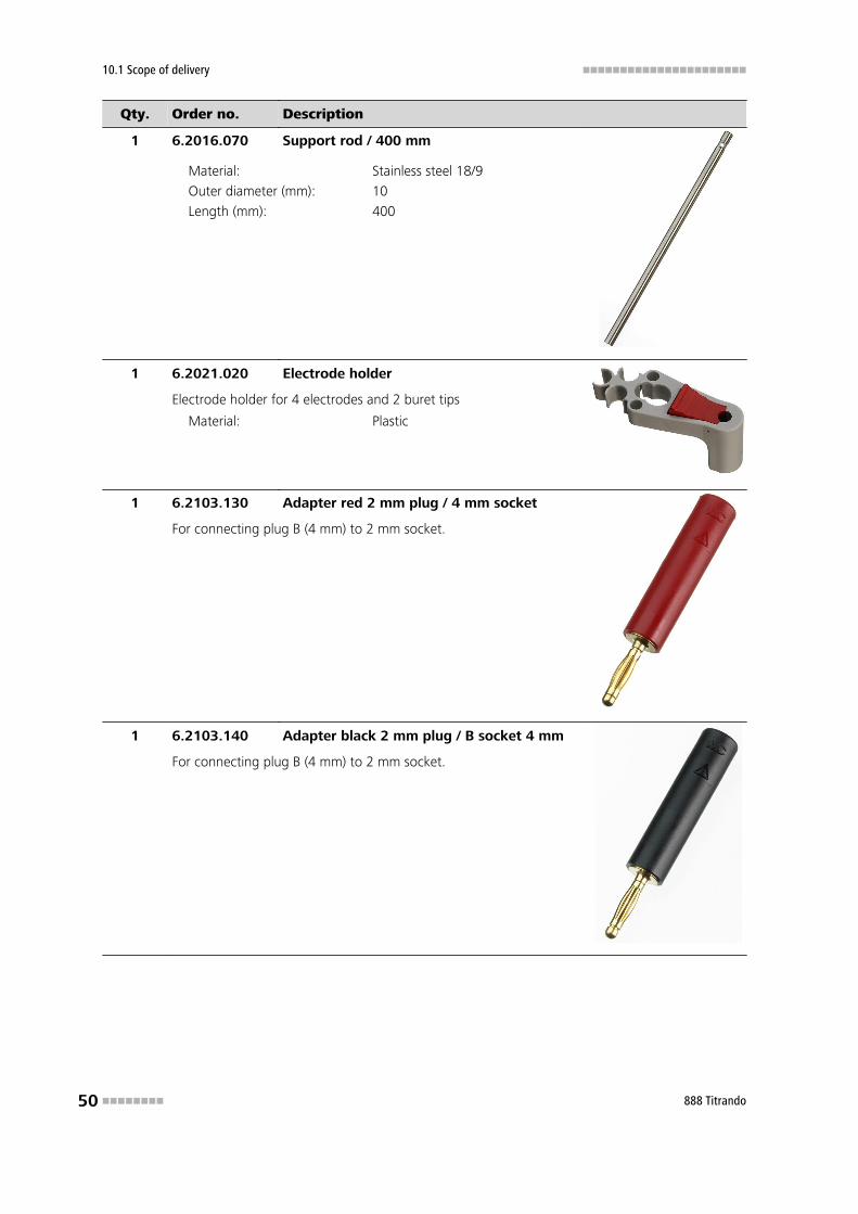
1 6.2001.060 Base-plate without support rod
For mounting stirrers
1 6.2013.010 Clamping ring
For stand rods of 10 mm diameter
Material: Metal
Width (mm): 20
Height (mm): 16
10.1 Scope of delivery ■■■■■■■■■■■■■■■■■■■■■■
50 ■■■■■■■■ 888 Titrando
Qty. Order no. Description
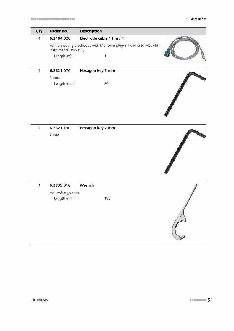
1 6.2016.070 Support rod / 400 mm
Material: Stainless steel 18/9
Outer diameter (mm): 10
Length (mm): 400
1 6.2021.020 Electrode holder
Electrode holder for 4 electrodes and 2 buret tips
Material: Plastic
1 6.2103.130 Adapter red 2 mm plug / 4 mm socket
For connecting plug B (4 mm) to 2 mm socket.
1 6.2103.140 Adapter black 2 mm plug / B socket 4 mm
For connecting plug B (4 mm) to 2 mm socket.
■■■■■■■■■■■■■■■■■■■■■■ 10 Accessories
888 Titrando ■■■■■■■■ 51
Qty. Order no. Description
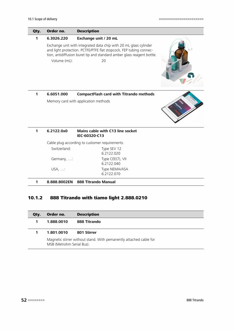
1 6.2104.020 Electrode cable / 1 m / F
For connecting electrodes with Metrohm plug-in head G to Metrohminstruments (socket F).
Length (m): 1
1 6.2621.070 Hexagon key 5 mm
5 mm.
Length (mm): 80
1 6.2621.130 Hexagon key 2 mm
2 mm
1 6.2739.010 Wrench
For exchange units.
Length (mm): 190
10.1 Scope of delivery ■■■■■■■■■■■■■■■■■■■■■■
52 ■■■■■■■■ 888 Titrando
Qty. Order no. Description
1 6.3026.220 Exchange unit / 20 mL
Exchange unit with integrated data chip with 20 mL glass cylinderand light protection. PCTFE/PTFE flat stopcock, FEP tubing connec-tion, antidiffusion buret tip and standard amber glass reagent bottle.
Volume (mL): 20
1 6.6051.000 CompactFlash card with Titrando methods
Memory card with application methods
1 6.2122.0x0 Mains cable with C13 line socketIEC-60320-C13
Cable plug according to customer requirements.
Switzerland: Type SEV 126.2122.020
Germany, …: Type CEE(7), VII6.2122.040
USA, …: Type NEMA/ASA6.2122.070
1 8.888.8002EN 888 Titrando Manual
10.1.2 888 Titrando with tiamo light 2.888.0210
Qty. Order no. Description
1 1.888.0010 888 Titrando
1 1.801.0010 801 Stirrer
Magnetic stirrer without stand. With pemanently attached cable forMSB (Metrohm Serial Bus).
■■■■■■■■■■■■■■■■■■■■■■ 10 Accessories
888 Titrando ■■■■■■■■ 53
Qty. Order no. Description
1 6.0262.100 Ecotrode Plus
Excellent durability in routine work at a fair price
Measuring range: 0...13
Measuring unit: pH
Temperature range: 0...80
Diaphragm: Fixed ground-joint diaphragm
Shaft length to head (mm): 125
Reference electrolyte type: c(KCl) = 3 mol/L
Bridge electrolyte type: c(KCl) = 3 mol/L
Temperature sensor: None
1 6.1903.020 Stirring bar / 16 mm
Stirring Bar with magnetic core, PTFE coated, length 16 mm
Material: PTFE
Outer diameter (mm): 4
Length (mm): 16
1 6.1903.030 Stirring bar / 25 mm
Stirring Bar with magnetic core, PTFE coated, length 25 mm
Material: PTFE
Outer diameter (mm): 5
Length (mm): 25
10.1 Scope of delivery ■■■■■■■■■■■■■■■■■■■■■■
54 ■■■■■■■■ 888 Titrando
Qty. Order no. Description
1 6.2001.060 Base-plate without support rod
For mounting stirrers
1 6.2013.010 Clamping ring
For stand rods of 10 mm diameter
Material: Metal
Width (mm): 20
Height (mm): 16
1 6.2016.070 Support rod / 400 mm
Material: Stainless steel 18/9
Outer diameter (mm): 10
Length (mm): 400
1 6.2021.020 Electrode holder
Electrode holder for 4 electrodes and 2 buret tips
Material: Plastic
■■■■■■■■■■■■■■■■■■■■■■ 10 Accessories
888 Titrando ■■■■■■■■ 55
Qty. Order no. Description
1 6.2103.130 Adapter red 2 mm plug / 4 mm socket
For connecting plug B (4 mm) to 2 mm socket.
1 6.2103.140 Adapter black 2 mm plug / B socket 4 mm
For connecting plug B (4 mm) to 2 mm socket.
1 6.2104.020 Electrode cable / 1 m / F
For connecting electrodes with Metrohm plug-in head G to Metrohminstruments (socket F).
Length (m): 1
1 6.2151.000 Cable USB A - mini-DIN 8P
Cable connecting a Titrando, USB Sample Processors, Dosing Inter-face, Robotic Titrosampler to a PC (USB connection, type A) and forconnecting further Titrandos. USB A - Controller.
Length (m): 1.8
10.1 Scope of delivery ■■■■■■■■■■■■■■■■■■■■■■
56 ■■■■■■■■ 888 Titrando
Qty. Order no. Description
1 6.2621.070 Hexagon key 5 mm
5 mm
Length (mm): 80
1 6.2621.130 Hexagon key 2 mm
2 mm
1 6.2739.010 Wrench
For exchange units.
Length (mm): 190
1 6.3026.220 Exchange unit / 20 mL
Exchange unit with integrated data chip with 20 mL glass cylinderand light protection. PCTFE/PTFE flat stopcock, FEP tubing connec-tion, antidiffusion buret tip and standard amber glass reagent bottle.
Volume (mL): 20
1 6.6056.131 tiamo light CD: 1 Lizenz
■■■■■■■■■■■■■■■■■■■■■■ 10 Accessories
888 Titrando ■■■■■■■■ 57
Qty. Order no. Description
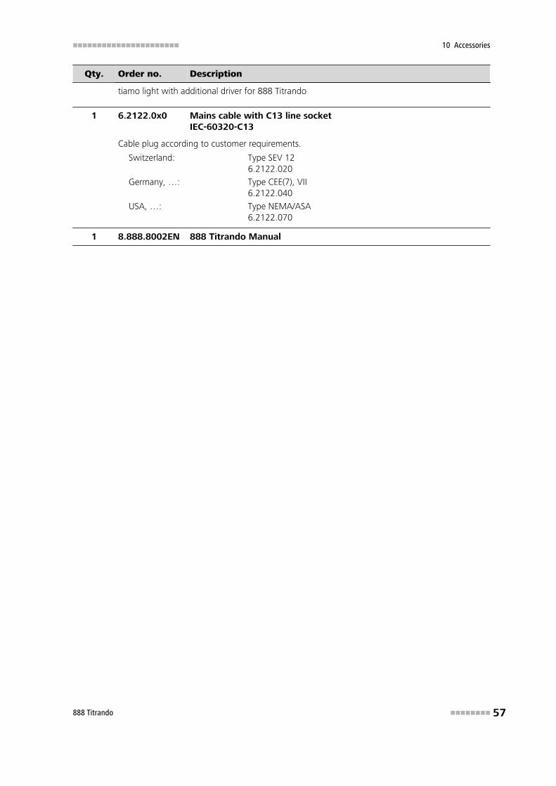
tiamo light with additional driver for 888 Titrando
1 6.2122.0x0 Mains cable with C13 line socketIEC-60320-C13
Cable plug according to customer requirements.
Switzerland: Type SEV 126.2122.020
Germany, …: Type CEE(7), VII6.2122.040
USA, …: Type NEMA/ASA6.2122.070
1 8.888.8002EN 888 Titrando Manual
Index ■■■■■■■■■■■■■■■■■■■■■■
58 ■■■■■■■■ 888 Titrando
Index
Numbers/Symbols685 Dosimat ............................ 15700 Dosino .............................. 15800 Dosino .............................. 15801 Stirrer ................................ 16803 Ti Stand ............................. 16804 Ti Stand ............................. 16805 Dosimat ............................ 15
BBalance .................................... 19Bluetooth adapter
Connecting ........................ 24
CCAL ............................................ 3Calibration mode
Calibration of pH electrodes . 3Cock blocked ........................... 35Computer
Connecting ........................ 12Connecting
Balance .............................. 19Barcode reader ................... 22Bluetooth adapter .............. 24Computer ........................... 12Dosing devices ................... 15iConnect ............................ 28MSB devices ....................... 14PC keyboard ....................... 21Printer ................................ 18Remote box ........................ 17Stirrer or titration stand ...... 16Touch Control .................... 11USB hub ............................. 23
Connecting a barcode reader . . . 22Connector
Controller ............................. 9iConnect .............................. 9ISE electrode ........................ 9iTrode .................................. 9MSB ................................. 2, 9pH electrode ........................ 9Polarizable electrode ............ 9Redox electrode ................... 9Reference electrode .............. 9Temperature sensor .............. 9USB .................................. 2, 9
Contact pins ............................... 8Controller cable 6.2151.000 .... 12
Coupling .................................... 8
DData chip ................................. 35DET ............................................ 3Device software
Update ................................. 2Differential potentiometry ........ 29Dosing command ....................... 3Dosing devices
Connecting ........................ 15Driver
Install ................................. 12
EElectrostatic charge .................... 6Exchange unit .............. 31, 36, 35
GGLP .......................................... 34Guarantee ................................ 47Guide openings .......................... 8
IiConnect
Connecting ........................ 28Installation
Driver ................................. 12Instrument description ................ 2Instrument type .......................... 9
KKeyboard ................................. 21
LLED
On ................................. 8, 35Status ........... 8, 32, 35, 36, 35
MMagnetic stirrer
Connecting ........................ 16Mains connection ....................... 9Mains voltage ............................. 6Maintenance ............................ 33MEAS ......................................... 3Measuring interface ................ 2, 9Measuring mode ........................ 3
Amperometric measurement 3MEAS ................................... 3
Potentiometric pH measure-ment .................................... 3Potentiometric voltage meas-urement ............................... 3Temperature measurement ... 3Voltametric measurement ..... 3
MET ........................................... 3Metrohm Serial Bus MSB, see also"MSB" ...................................... 14MSB
Connecting devices ............ 14MSB.Connector .......................... 2
OOverview of the instrument ........ 8
PPC keyboard ............................. 21Pins .......................................... 37Piston blocked .......................... 35Printer ...................................... 18
QQuality Management ................ 34
RRemote
Input .................................. 38Interface ............................. 37Output ............................... 38
Remote boxConnecting ........................ 17Pin assignment ................... 37
SSafety instructions ...................... 5Serial number ............................. 9Service ....................................... 5Service Agreement ................... 34SET ............................................. 3Spindle ....................................... 8Stirrer
Connecting ........................ 16System test ............................... 11
TTitrando system .......................... 1Titration mode ........................... 3
DET ...................................... 3MET ..................................... 3

■■■■■■■■■■■■■■■■■■■■■■ Index
888 Titrando ■■■■■■■■ 59
SET ....................................... 3Titration stand .......................... 16
Connecting ........................ 16Titration vessel
Setting up .......................... 29Touch Control
Connecting ........................ 11
UUpdate
Device software .................... 2USB connector ........................... 2USB hub
Connecting ........................ 23
VValidation ................................. 34
WWarranty .................................. 47Windows .................................. 13