
Manual: 7 Series Flame Arrestor - Emerson burning should not be allowed in any flame arrestor,...
12
North America Only D103829X012 Instruction Manual February 2015 7 Series www.enardo.com Figure 1. 7 Series Flame Arrestor 7 Series Flame Arrestor Table of Contents Introduction .................................................................. 1 Specifications .............................................................. 2 Principle of Operation .................................................. 3 Factors Affecting Flame Arrestor Performance ........... 3 Installation ................................................................... 5 Maintenance ................................................................ 6 Recommended Spare Parts ...................................... 10 Parts Ordering ........................................................... 10 Parts List.................................................................... 10 WARNING ! Failure to follow these instructions or to properly install and maintain this equipment could result in an explosion, fire and/or chemical contamination causing property damage and personal injury or death. Enardo flame arrestors must be installed, operated and maintained in accordance with federal, state and local codes, rules and regulations and Emerson Process Management Regulator Technologies Tulsa, LLC (Emerson TM ) instructions. Call a qualified service person to service the unit. Installation, operation and maintenance procedures performed by unqualified person may result in improper adjustment and unsafe operation. Either condition may result in equipment damage or personal injury. Only a qualified person shall install or service the 7 Series flame arrestor. Introduction Scope of the Manual This Instruction Manual provides specifications, installation and maintenance instructions and parts ordering information for the 7 Series flame arrestor. Product Description 7 Series flame arrestors are designed to stop the propagation of confined low pressure deflagration. The 7 Series is typically used for end-of-line and near- end-of-line applications when the system operating pressure is near atmospheric levels and when there is minimal probability of a flame stabilizing on the flame arrestor element for an extended period. Designed with flanged connections, this arrestor allows removal of the flame cell element for easy cleaning and replacement without removing the arrestor body from the pipe connection. Standard housing construction is aluminum, carbon steel or
Transcript of Manual: 7 Series Flame Arrestor - Emerson burning should not be allowed in any flame arrestor,...

Nor
th A
mer
ica
Onl
yD
1038
29X
012
Instruction Manual
February 2015
7 Series
www.enardo.com
Figure 1. 7 Series Flame Arrestor
7 Series Flame Arrestor
Table of Contents
Introduction ..................................................................1Specifications ..............................................................2Principle of Operation ..................................................3Factors Affecting Flame Arrestor Performance ........... 3Installation ...................................................................5Maintenance ................................................................6Recommended Spare Parts ......................................10Parts Ordering ...........................................................10Parts List....................................................................10
WARNiNG!
Failure to follow these instructions or to properly install and maintain this equipment could result in an explosion, fi re and/or chemical contamination causing property damage and personal injury or death.Enardo fl ame arrestors must be installed, operated and maintained in accordance with federal, state and local codes, rules and regulations and Emerson Process Management Regulator Technologies Tulsa, LLC (EmersonTM) instructions.Call a qualifi ed service person to service the unit. installation, operation and maintenance procedures performed by unqualifi ed person may result in improper adjustment and unsafe operation. Either condition may result in equipment damage or personal injury. Only a qualifi ed person shall install or service the 7 Series fl ame arrestor.
introduction
Scope of the ManualThis Instruction Manual provides specifi cations, installation and maintenance instructions and parts ordering information for the 7 Series fl ame arrestor.
Product Description7 Series fl ame arrestors are designed to stop the propagation of confi ned low pressure defl agration. The 7 Series is typically used for end-of-line and near-end-of-line applications when the system operating pressure is near atmospheric levels and when there is minimal probability of a fl ame stabilizing on the fl ame arrestor element for an extended period.Designed with fl anged connections, this arrestor allows removal of the fl ame cell element for easy cleaning and replacement without removing the arrestor body from the pipe connection. Standard housing construction is aluminum, carbon steel or
Nor
th A
mer
ica
Onl
y
7 Series
2
7 / - -
7 Series Housing Size
Connection Size
NEC Housing Material
Element Material
Connection Type
Options
Blank = ConcentricE = Eccentric
04 = 4 in. through
72 = 72 in.
01 = 1 in. through
36 = 36 in.
Gas GroupBCD
A = AluminumC = Carbon steel4 = 304 SST6 = 316 SSTH = Hastelloy®
E = Exotic
A = Aluminum4 = 304 SST6 = 316 SSTH = Hastelloy®
E = Exotic
F = Flat face flange
R = Raised face flange
1 = Drain Port2 = Pressure Tap 3 = Temperature
Probe Tap4 = Miscellaneous5 = Protective
Coating6 = Special
Feature
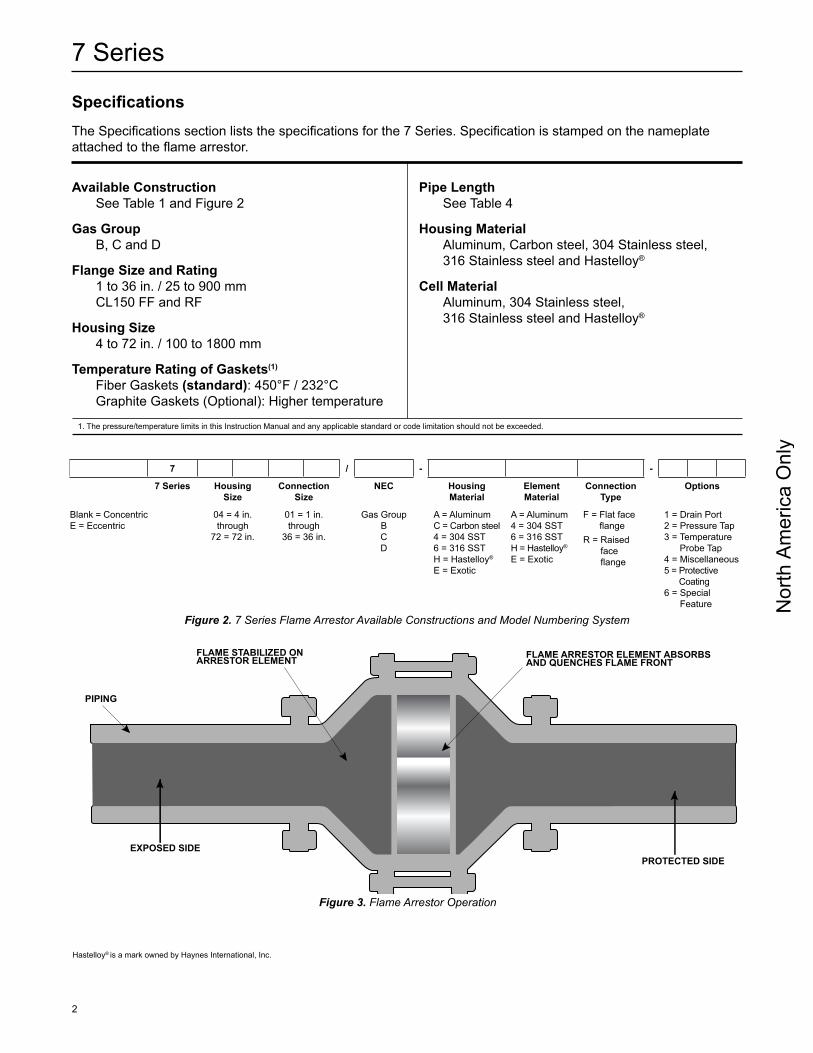
Figure 2. 7 Series Flame Arrestor Available Constructions and Model Numbering System
Hastelloy® is a mark owned by Haynes International, Inc.
Specifications The Specifications section lists the specifications for the 7 Series. Specification is stamped on the nameplate attached to the flame arrestor.
Available ConstructionSee Table 1 and Figure 2
Gas GroupB, C and D
Flange Size and Rating1 to 36 in. / 25 to 900 mmCL150 FF and RF
Housing Size4 to 72 in. / 100 to 1800 mm
Temperature Rating of Gaskets(1)
Fiber Gaskets (standard): 450°F / 232°C Graphite Gaskets (Optional): Higher temperature
1. The pressure/temperature limits in this Instruction Manual and any applicable standard or code limitation should not be exceeded.
Pipe LengthSee Table 4
Housing MaterialAluminum, Carbon steel, 304 Stainless steel, 316 Stainless steel and Hastelloy®
Cell MaterialAluminum, 304 Stainless steel, 316 Stainless steel and Hastelloy®
Figure 3. Flame Arrestor Operation
FLAME STABILIZED ONARRESTOR ELEMENT
PIPING
EXPOSED SIDE
FLAME ARRESTOR ELEMENT ABSORBSAND QUENCHES FLAME FRONT
PROTECTED SIDE

Nor
th A
mer
ica
Onl
y
3
7 Series
stainless steel. The element is available in stainless steel. Special material and protective coating are available on request.
Principle of OperationFlame arrestor allows gas to pass though it but stops flame in order to prevent a larger fire of explosion. Arrestor prevents flame by absorbing and dissipating the heat from flame as it attempts to travel through the spiral wound crimped ribbon flame cells. These cells allow maximum flow with maximum protection.
Factors Affecting Flame Arrestor Performance
Gas Group
WARNiNG!
Methanol is classified by the National Electrical Code (NEC) as a Group-D vapor. However, our lab tests indicate that methanol exhibits characteristics unlike other Group-D vapors under certain conditions. We therefore recommend that an arrestor rated for Group-C vapors be specified for methanol service.
Table 1. 7 Series Available Construction
7 SERiES iN-LiNE FLAME ARRESTOR CARbON STEEL AND STAiNLESS STEEL HOuSiNGS CONSTRuCTiON
ModelFlange Size Housing Size
in. mm in. mm
70401 1 25 4 100
70402 2 50 4 100
70602 2 50 6 150
70802 2 50 8 200
70603 3 75 6 150
70803 3 75 8 200
70804 4 100 8 200
71006 6 150 10 250
71206 6 150 12 300
71408 8 200 14 350
71608 8 200 16 400
71810 10 250 18 450
72010 10 250 20 500
72212 12 300 22 550
72412 12 300 24 600
7 SERiES iN-LiNE FLAME ARRESTOR ALuMiNuM HOuSiNG CONSTRuCTiON
ModelFlange Size Housing Size
in. mm in. mm
70802 2 50 8 200
70803 3 75 8 200
70804 4 100 8 200
71006 6 150 10 250
71206 6 150 12 300
71408 8 200 14 350
71608 8 200 16 400
72010 10 250 20 500
72212 12 300 22 550
72412 12 300 24 600

Nor
th A
mer
ica
Onl
y
7 Series
4
The type of gas in the system determines its gas grouping and therefore predetermines the type of arrestor element required. The element must be designed to accommodate the specific gas group that could possibly ignite and propagate in the system. The more explosive gases require the flame cell to absorb the heat more quickly and efficiently. The National Electrical Code (NEC) groups gases into A, B, C, D and G.M. categories depending on the Maximum Experimental Safe Gap (MESG) of the gas.
Maximum Experimental Safe Gap (MESG)
WARNiNG!
Verify that the Flame Arrestor being installed has the appropriate gas group rating for your process. This information is shown on the nameplate attached to the element housing. Do not remove or alter this nameplate.
The measurement of the maximum gap between two equatorial flanges on a metal sphere that will prevent a flame from being transmitted from the sphere to the surrounding flammable mixture. MESG is dependent on gas composition. The stoichiometric mixture (the ideal air/fuel ratio for the most efficient combustion) is used to determine the minimum MESG for a given gas. See Table 2 for the MESG per gas group.
Maximum initial Operating PressureThis is the pressure of the system at or near static flow conditions. High pressure deflagration can occur more easily at higher system operating pressures than at pressures near atmospheric. Elevated pressures condense the ignitable gas giving the flame more matter and energy to release thereby boosting the flame heat intensity. Verify that your system pressure at or near static flow conditions does not exceed the maximum pressure shown on the arrestor’s name tag.
Endurance burn Time
WARNiNG!
unlimited burning should not be allowed in any flame arrestor, regardless of its burn time rating. if burning can occur for a period exceeding 2 minutes starting at ambient temperature, it is recommended that a temperature alarm and shutdown system be installed.
Endurance burn time is the time it takes for a stabilized flame, at greatest heat saturation conditions, to heat the arrestor element above the auto-ignition temperature of the process gas stream resulting in flame propagation through the arrestor. See Table 3 for the 7 Series endurance burning time.
Table 2. Maximum Experimental Safe Gap (MESG)
NATiONAL ELECTRiCAL CODE (NEC)MESG
TEST GAS LiSTin. mm
Group B 0.011 0.28 Hydrogen
Group C 0.026 0.65 Ethylene
Group D 0.035 0.90 Propane
Table 3. 7 Series Flame Arrestor Endurance Burn Time
GAS GROuP MAxiMuM iNiTiAL PRESSuRE
ENDuRANCE buRN TiMEpsia kPa
D 15.4 106 30 minutes (Steel and Stainless steel models up to 12 in. and under)
D 15.4 106 5 minutes (all other Group-D)
C 15.4 106 5 minutes
B 15.4 106 2 minutes

Nor
th A
mer
ica
Onl
y
5
7 Series
Table 4. 7 Series Pipe Length Rules
GAS GROuP “b” GAS GROuP “C” GAS GROuP “D”
Maximum length of pipe between the flame arrestor and the ignition source without bends or other obstructions.
4 ft. / 1.2 m., open ended pipe 6 ft. / 2 m., open ended pipe 20 ft. / 6 m.
Maximum length of pipe between the flame arrestor and the ignition source with a maximum of one 90°
bend. Multiple bends or any additional obstructions are not recommended.
Not Recommended With a Bend. 6 ft. / 2 m., open ended pipe 20 ft. / 6 m.
Pipe LengthsExtended lengths of pipe allow the flame to advance into more severe states of flame propagation such as high pressure deflagration or detonations. 7 Series Flame Arrestors should be installed in accordance with the Table 4.
Bends and/or Flow Obstructions
CAuTiON
For maximum safety, avoid bends and flow obstructions within 10 pipe diameters on the protected side of the flame arrestor.
Bends in piping, pipe expansions and/or contractions, valves, orifice plates or flow obstructing devices of any kind contribute to turbulent flow. Turbulent flow enhances mixing of the combustible gases, greatly increasing the combustion intensity. This can result in increased flame speeds, higher flame temperatures and higher flame front pressures than would occur in normal flow conditions.
installation
WARNiNG!
Always make sure that the system is at atmospheric pressure and there is no ignitable gas that could flash when either installing or maintaining the unit.
ConnectionEnardo flame arrestors are normally provided with CL150 raised or flat face flanges. Other flange patterns are available upon request. Make sure the companion flanges installed in adjacent piping match the flanges on the flame arrestor.
Standard compressed fiber gaskets that withstands temperatures of 450°F / 232°C are standard. Graphite gaskets with higher temperature ratings are available as an option.
Positioning
CAuTiON
The flame arrestor is fitted with lugs for lifting the element assembly during servicing operations. These lugs are not intended for lifting the entire unit during installation. Damage to the flame arrestor may result from improper lifting. Heavy units should be lifted using appropriately rated Nylon (PA)straps rigged on the outside of the tension studs.
The flame arrestor should be positioned such that the element is accessible for removal. The tension studs are supplied with jacking nuts on one half of the bolting circumference. Install the unit so that the jacking nuts (on the inside of the studs) are positioned on the opposite side from the direction that the element assembly will be removed.Models that have drain plugs are designed for horizontal installation and should be installed with the drain plugs aligned at the bottom of the unit. Models that have pressure taps are designed to allow pressure gauges to be installed on both sides of the flame cell assembly to determine blockage. The pressure taps should be aligned at the top to allow easy viewing of the gauges. Units that are equipped with optional internal cleaning systems should be connected to a source of cleaning media such as water, steam or other suitable solvent.
Flow DirectionThe Enardo flame arrestor is bi-directional and can be installed either vertically or horizontally. Consideration should be given to non-symmetrical assemblies that

Nor
th A
mer
ica
Onl
y
7 Series
6
include features such as clean-out ports, temperature monitoring device or other options that might have a preferred installation direction to suit the needs of the customer.
Piping Expansions and Reductions Adjacent to Flame Arrestors
WARNiNG!
No instrument, tubing or other device whatsoever shall circumvent the flame arrestor in such a manner to allow a flame path to exist around the flame element of the arrestor. When instrumentation is installed in such a manner that it creates a path circumventing the flame element of an arrestor, measures must be taken to prevent passage of flame through the instrumentation device and/or system. instrumentation must be capable of withstanding the maximum and minimum pressures and temperatures to which the device may be exposed.
An Enardo flame arrestor may be installed in any vapor control line that is smaller than or equal to the nominal pipe diameter of the arrestor’s connection flanges. When it is necessary to increase the diameter of the piping on the downstream side of the flame arrestor, a length of pipe at least 120 pipe diameters must be installed between the flame arrestor and the expansion. A pipe diameter is considered as the inside diameter of pipe having a nominal size equal to the flame arrestor’s connecting flanges.
Maintenance
WARNiNG!
Flame cells must be inspected for damage immediately following a deflagration and/or stabilized burn.
1. Carefully remove the element assembly from the arrestor and place it on a soft surface such as plywood.
2. Inspect the flame cell visually for any signs of corrosion or other damage.
3. Inspect the flame cell with a calibrated pin gauge to ensure maximum crimp size openings do not exceed the following values for their respective gas group:
• Explosion Group D – 0.051 in. / 1.3 mm • Explosion Group C – 0.038 in. / 0.965 mm • Explosion Group B – 0.017 in. / 0.432 mm
4. If any damage is noted, or crimp openings exceed maximum size allowable, replace the element assembly.
5. Keep the element openings clean to prevent loss of efficiency in absorbing heat. Remove the element assembly and clean the elements to prevent the openings from becoming clogged with particulate matter. Clean the element with a suitable cleaning media (solvent, soap, water or steam) then blow dry using compressed air. Be careful not to damage or dent the cell openings as this would hamper the effectiveness of the unit. Do not clean the arrestor elements by rodding to remove blockages, as this practice will damage the elements and seriously impair the arrestor’s performance. If the arrestor element cannot be cleaned satisfactorily, replace it.
6. For best cleaning results, use a high pressure sprayer with spray wand (1500 to 3000 psig / 103 to 207 bar) to clean the entire element surface. Hold the spray nozzle perpendicular to the surface being cleaned to maximize spray media penetration into the element. Alternately spray each side of the element surface until clean.
7. The cleaning interval should be governed by the amount and type of particulate in the system to which it is installed and must be determined by the user. To determine the maintenance interval, the user should check the element in the first few months of operation to find how quickly particulate accumulates in the cells.
8. After cleaning, thoroughly inspect the element for damage. If damaged, replace it.
Noteunder no circumstance should the element bank be disassembled from its shell for cleaning or replacement. The element section must be replaced as a complete assembly.Cleaning of units equipped with this system may be accomplished in several ways including periodic cleaning using manually operated valves, by use of

Nor
th A
mer
ica
Onl
y
7
7 Series
an automated cycle timing method or by having the cleaning operation initiated whenever the pressure loss across the arrestor element exceeds a predetermined value.
Element Assembly, Disassembly and Reassembly instructions
WARNiNG!
isolate gas supply and bring system to atmospheric pressure to prevent ignitable gas from flashing while performing maintenance.
1. Loosen all jacking (inside) nuts on tension studs between conical sections of the flame arrestor.
2. Tighten the inside jacking nuts on the tension studs forcing the two conical sections apart. When the two flange faces have separated, remove the tension studs that do not have inside jacking nuts so that the element assembly can be removed. The inside jacking nuts are installed on all tension studs that facilitate jacking the unit apart. The inside jacking nuts are not installed on tension studs that are taken out, for ease of removal.
CAuTiON
Element assemblies are heavy and will require the use of adequate equipment and manpower to prevent injury.
3. Thoroughly clean the gasket sealing faces being careful not to damage the sealing surface. For reassembly, lightly grease one side of a new gasket and place it in the machined recess of each interior flange on the two conical sections.
4. Replace the flame element assembly with a new assembly or properly cleaned and inspected existing unit.
5. Loosen the jacking nuts on the tension rods until the flame cell assembly seats onto the gaskets.
6. Replace all tensioning studs and hand tighten the outer nuts. Check to be sure that all the jacking nuts are completely loose and not making contact with the flange face.
Torquing instruction
CAuTiON
Excessive or uneven torquing can cause permanent damage to gaskets and housing.
Tools/Supplies Required
• Torque wrench appropriate for the specified torque• Socket wrenches of the proper size to fit the hex
nuts being tightened• Molydisulfide based lubricating paste,
Molykote® G-n or equivalent• Brush suitable for applying lubricant to the studs• Wiping rags necessary for the clean up of
excessive lubricant
Procedure
1. Use studs and nuts that are free of visible contamination and corrosion.
2. Apply lubricant to the threads of the stud protruding outboard of the interior flanges and to the face of the hex nuts which will contact the flange.
3. Assemble the nuts to the studs such that the amount of thread extending outboard beyond the nut is approximately equal on both ends.
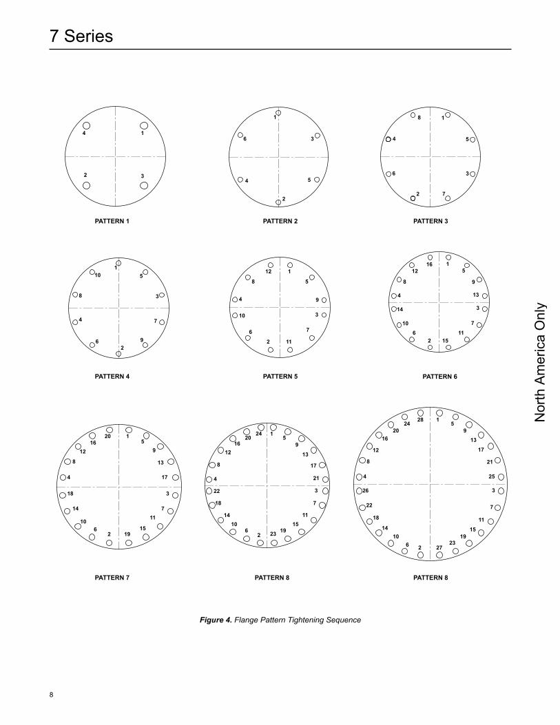
4. Tighten the nuts to the torque values shown in Table 5 following the designated sequence, repeating the sequence as shown. Flange pattern tightening sequences are shown in Figure 4.
Bolt Lubrication
Lubrication will affect required torque of clean fasteners in good condition more than any other factor. In fact, 90% of applied torque goes to overcome friction while only 10% actually stretches the bolt. Table 5 assumes that only machine oil is used as a lubricant. Table 6 shows a list of several common lubricants and their effect on torque required to stretch bolts to 50% of their yield strength. Most are available from local bearing distributors.
Molykote® G-n is a mark owned by Dow Corning Corporation.
Nor
th A
mer
ica
Onl
y
7 Series
8
Figure 4. Flange Pattern Tightening Sequence
3
5
1
2
4
6
7
8
1
2 3
4
1
2
3
4 5
6
1
58
12
94
10
6
2 11
7
3
1612
8
4
14
106
2 1511
7
3
13
9
51
2016
12
8
4
18
14
106
2 1915
117
3
15
9
13
17
1
2
3
4
5
6
7
8
9
10
24 15
9
13
17
21
3
7
1115
192326
1014
18
22
4
8
1216
20
28 15
913
17
21
25
3
7
11
1519
23276 2
1014
18
22
26
4
8
12
1620
24
PATTERN 1
PATTERN 4
PATTERN 7 PATTERN 8 PATTERN 8
PATTERN 5 PATTERN 6
PATTERN 2 PATTERN 3

Nor
th A
mer
ica
Onl
y
9
7 Series
DESCRiPTiON COEFFiCiENT OF FRiCTiON MuLTiPLY TORQuE VALuE iN TAbLE 5 bY
Machine Oil f = 0.15 1.00
API SA2 Grease f = 0.12 0.80
Never-Seez® (Ni base) f = 0.11 0.73
Never-Seez® (Cu base) f = 0.10 0.67
Molykote® G-n Paste f = 0.06 0.40
Table 6. Torque Correction Factors for Common Lubricants
7 SERiES FLAME ARRESTORS WiTH ALuMiNuM END SECTiONS ONLY TiGHTENiNG STEPS AND TORQuE (LbF-FT / N•m)
Model Pattern(2) Step 1 Step 2
70802-A, 70803-A, 70804-A 1 Snug 25 / 34
71006-A, 71206-A, 71408-A 2 Snug 25 / 34
71608-A 3 Snug 25 / 34
72010-A 3 Snug 50 / 68
72212-A, 72412-A, 72414-A, 72614-A, 72616-A 5 Snug 50 / 68
73016-A 7 Snug 50 / 68
73216-A 8 Snug 50 / 68
7 SERiES FLAME ARRESTORS WiTH STEEL OR STAiNLESS STEEL END SECTiONS ONLY TiGHTENiNG STEPS AND TORQuE (LbF-FT / N•m)
Model Pattern(2) Step 1 Step 2 Step 3 Step 4 Step 5
70401, 70401.5, 70602, 70603, 70604, 70802, 70803, 70804 1 Snug 20 / 27 50 / 68
71006, 71206 2 Snug 20 / 27 50 / 68
71408 2 Snug 25 / 34 60 / 81
71608 3 Snug 25 / 34 50 / 68 80 / 108
71810 3 Snug 25 / 34 50 / 68 90 / 122
72010 3 Snug 25 / 34 50 / 68 75 / 102 100 / 136
72212 4 Snug 25 / 34 50 / 68 85 / 115
72412 4 Snug 35 / 47 70 / 95 100 / 136 130 / 176
72614, 72616 4 Snug 35 / 47 70 / 95 100 / 136 140 / 190
72814 5 Snug 35 / 47 70 / 95 100 / 136 125 / 169
73016 5 Snug 35 / 47 70 / 95 100 / 136 130 / 176
73216 6 Snug 35 / 47 70 / 95 105 / 142
73420 6 Snug 35 / 47 70 / 95 115 / 156
7 SERiES FLAME ARRESTORS WiTH STEEL OR STAiNLESS STEEL END SECTiONS ONLY TiGHTENiNG STEPS AND TORQuE (LbF-FT / N•m)
Model Pattern(2) Step 1 Step 2 Step 3 Step 4 Step 5
73620 6 Snug 35 / 47 70 / 95 100 / 136 120 / 163
74020, 74024, 74824 7 Snug 35 / 47 70 / 95 130 / 176
77036 8 Snug 35 / 47 70 / 95 130 / 176 200 / 271
1. Use machine oil as lubricant. See Bolt Lubrication section (Table 6) and torque correction factors for other lubricants.2. See Figure 4.
Table 5. Tightening Steps and Torque Values(1)(2)
Molykote® G-n is a mark owned by Dow Corning Corporation.Never-Seez® is a mark owned by Bostik, Inc.
Nor
th A
mer
ica
Onl
y
7 Series
10
MODELPART NuMbER
Standard Gasket (Compressed Fiber)
High Temperature Gasket (Graphite Coated 316 Stainless Steel)
70802-A, 70803-A and 70804-A 7008102 7049202
71004-A 7008135 7049235
71206-A 7008136 7049236
71408-A 7008124 7049224
71608-A 7008107 7049207
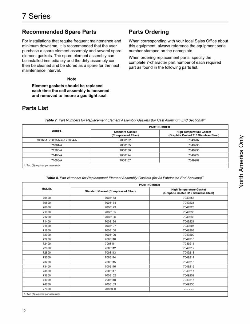
1. Two (2) required per assembly.
Table 7. Part Numbers for Replacement Element Assembly Gaskets (for Cast Aluminum End Sections)(1)
MODELPART NuMbER
Standard Gasket (Compressed Fiber) High Temperature Gasket (Graphite Coated 316 Stainless Steel)
70400 7008153 7049253
70600 7008134 704923470800 7008123 7049223
71000 7008135 7049235
71200 7008136 704923671400 7008124 704922471600 7008107 704920771800 7008108 704920872000 7008109 704920972200 7008110 704921072400 7008111 704921172600 7008112 704921272800 7008113 704921373000 7008114 704921473200 7008115 704921573400 7008116 704921673600 7008117 704921773800 7008152 704925274000 7008118 704921874800 7008133 704923377000 7083300 - - - - - -
1. Two (2) required per assembly.
Table 8. Part Numbers for Replacement Element Assembly Gaskets (for All Fabricated End Sections)(1)
Parts List
Recommended Spare PartsFor installations that require frequent maintenance and minimum downtime, it is recommended that the user purchase a spare element assembly and several spare element gaskets. The spare element assembly can be installed immediately and the dirty assembly can then be cleaned and be stored as a spare for the next maintenance interval.
NoteElement gaskets should be replaced each time the cell assembly is loosened and removed to insure a gas tight seal.
Parts OrderingWhen corresponding with your local Sales Office about this equipment, always reference the equipment serial number stamped on the nameplate.When ordering replacement parts, specify the complete 7-character part number of each required part as found in the following parts list.

Nor
th A
mer
ica
Onl
y
11
7 Series
HOuSiNG MATERiAL Aluminum Aluminum Carbon Steel Carbon Steel 304 Stainless
Steel Carbon Steel 316 Stainless Steel
FLAME CELL
MATERiALAluminum 304 Stainless
Steel Aluminum 304 Stainless Steel
304 Stainless Steel
316 Stainless Steel
316 Stainless Steel
MODEL PART NuMbER
70400 7011741 7011742 7002246 7002261 7002275 7048509 7002201
70600 7011734 7011735 7048514 7048515 7002279 7048516 7002266
70800 7011704 7011712 7002253 7002203 7002217 7002211 7002202
71000 7011705 7011713 7002254 7002204 7002291 7002214 7002292
71200 7011706 7011702 7002256 7002239 7002233 7002283 7002293
71400 7011707 7011714 7002263 7002228 7002223 7002262 7002268
71600 7011708 7011715 7002248 7002247 7002234 7002280 7002297
71800 7011736 7011737 7002252 7002251 7002289 7002250 7048518
72000 7011709 7011716 7002213 7002249 7048519 7002218 7002296
72200 7011710 7011717 7002240 7002207 7048520 7048510 7048521
72400 7011711 7011718 7002258 7002265 7002232 7002264 7002276
72600 7011703 7011738 7048522 7048523 7048524 7048525 7048526
72800 7011726 7011739 7048505 7048527 7048528 7002281 7048529
73000 7011721 7011740 7002243 7002270 7048530 7048531 7048532
73200 7011732 7011733 7002230 7048533 7048534 7048535 7048536
73400 7011743 7011744 7048537 7002226 7048538 7048539 7048540
73600 7011745 7011746 7048541 7002241 7048542 7048543 7002274
73800 7011747 7011748 7048544 7048545 7048546 7048547 7048548
74000 7011749 7011750 7048549 7002273 7048550 7048551 7002209
74800 7011751 7011752 7048552 7002288 7048553 7048554 7048555
Table 9. Replacement Element Assemblies Part Numbers (Group D Gas)
HOuSiNG MATERiAL Aluminum Aluminum Carbon Steel Carbon Steel 304 Stainless
Steel Carbon Steel 316 Stainless Steel
FLAME CELL MATERiAL Aluminum 304 Stainless
Steel Aluminum 304 Stainless Steel
304 Stainless Steel
316 Stainless Steel
316 Stainless Steel
MODEL PART NuMbER
70400 7011753 7011754 7048556 7048557 7048502 7048558 7048559
70600 7011755 7011756 7048560 7048561 7048562 7048563 7002231
70800 7011729 7011731 7048507 7002255 7002295 7002206 7048564
71000 7011757 7011758 7048506 7002259 7048501 7048565 7048566
71200 7011759 7011760 7048567 7002260 7048569 7048570 7048571
71400 7011761 7011762 7048572 7048573 7048574 7048575 7002245
71600 7011763 7011764 7048576 7048577 7048578 7048504 7048579
71800 7011765 7011766 7048580 7048581 7048582 7048583 7048584
72000 7011767 7011768 7048585 7002299 7048586 7048587 7048588
72200 7011769 7011770 7048589 7048590 7048591 7048592 7048593
72400 7011771 7011772 7048594 7048595 7048596 7048597 7002244
Table 10. Replacement Element Assemblies Part Numbers (Group C Gas)

Nor
th A
mer
ica
Onl
y
©Emerson Process Management Regulator Technologies Tulsa, LLC, 2015, Rev. F; All Rights Reserved
The Emerson logo is a trademark and service mark of Emerson Electric Co. All other marks are the property of their prospective owners. Enardo is a mark owned by Regulator Technologies Tulsa, LLC, a business of Emerson Process Management.
The contents of this publication are presented for informational purposes only, and while every effort has been made to ensure their accuracy, they are not to be construed as warranties or guarantees, express or implied, regarding the products or services described herein or their use or applicability. We reserve the right to modify or improve the designs or specifications of such products at any time without notice.
Emerson Process Management Regulator Technologies Tulsa, LLC does not assume responsibility for the selection, use or maintenance of any product. Responsibility for proper selection, use and maintenance of any Emerson Process Management Regulator Technologies Tulsa, LLC product remains solely with the purchaser.
Emerson Process ManagementRegulator Technologies Tulsa, LLC
9932 East 58th StreetTulsa, OK 74146-6411
Tel: +1 918 662 6161Fax: +1 918 662 0004
For further information visit www.enardo.com
7 Series
HOuSiNG MATERiAL Aluminum Aluminum Carbon Steel Carbon Steel 304 Stainless
Steel Carbon Steel 316 Stainless Steel
FLAME CELL MATERiAL Aluminum 304 Stainless
Steel Aluminum 304 Stainless Steel
304 Stainless Steel
316 Stainless Steel
316 Stainless Steel
MODEL PART NuMbER
70400 7011773 7011774 7048598 7048513 7002212 7048512 7002210
70600 7011775 7011776 7048599 7056501 7056502 7056503 7056504
70800 7011725 7011777 7056505 7002216 7002286 7048511 7002215
71000 7011778 7011779 7056506 7002205 7056507 7002290 7056509
71200 7011780 7011781 7056510 7002257 7002282 7056511 7002298
71400 7011782 7011783 7056512 7048508 7056513 7056514 7056515
71600 7011784 7011785 7056508 7056516 7056517 7056518 7056519
71800 7011786 7011787 7056520 7056521 7056522 7056523 7056524
72000 7011727 7011788 7056525 7056526 7056527 7056528 7056529
72200 7011789 7011790 7056530 7056531 7056532 7056533 7056534
72400 7011791 7011792 7056535 7056536 7056537 7056538 7056539
Table 11. Replacement Element Assemblies Part Numbers (Group B Gas)


