MANUAL: 5-WAY MANIFOLD - Task Force Tips · The 5-Way Manifold is a compact, ... All four 2.5”...
12
©Copyright Task Force Tips, Inc. 2011-2016 LIA-535 October 31, 2016 Rev04 MANUAL: 5-WAY MANIFOLD INSTRUCTIONS FOR SAFE OPERATION AND MAINTENANCE WARNING Read Instruction Manual before use. Operation of this manifold without understanding the manual and receiving proper training can be dangerous and is a misuse of this equipment. Download this manual from http://tft.com/. Call 800-348-2686 with any questions. NOTICE This Instruction Manual is intended to familiarize firefighters and maintenance personnel with the operation, servicing, and safety procedures associated with the 5-Way Manifold. NOTICE This manual should be kept available to all operating and maintenance personnel. OPERATING RANGE Pressure Max 300 PSI Pressure Min 10 PSI TASK FORCE TIPS, INC. MADE IN USA • www.tft.com 3701 Innovation Way, Valparaiso, IN 46383-9327 USA 800-348-2686 • 219- 462-6161 • Fax 219-464-7155
Transcript of MANUAL: 5-WAY MANIFOLD - Task Force Tips · The 5-Way Manifold is a compact, ... All four 2.5”...
©Copyright Task Force Tips, Inc. 2011-2016 LIA-535 October 31, 2016 Rev04
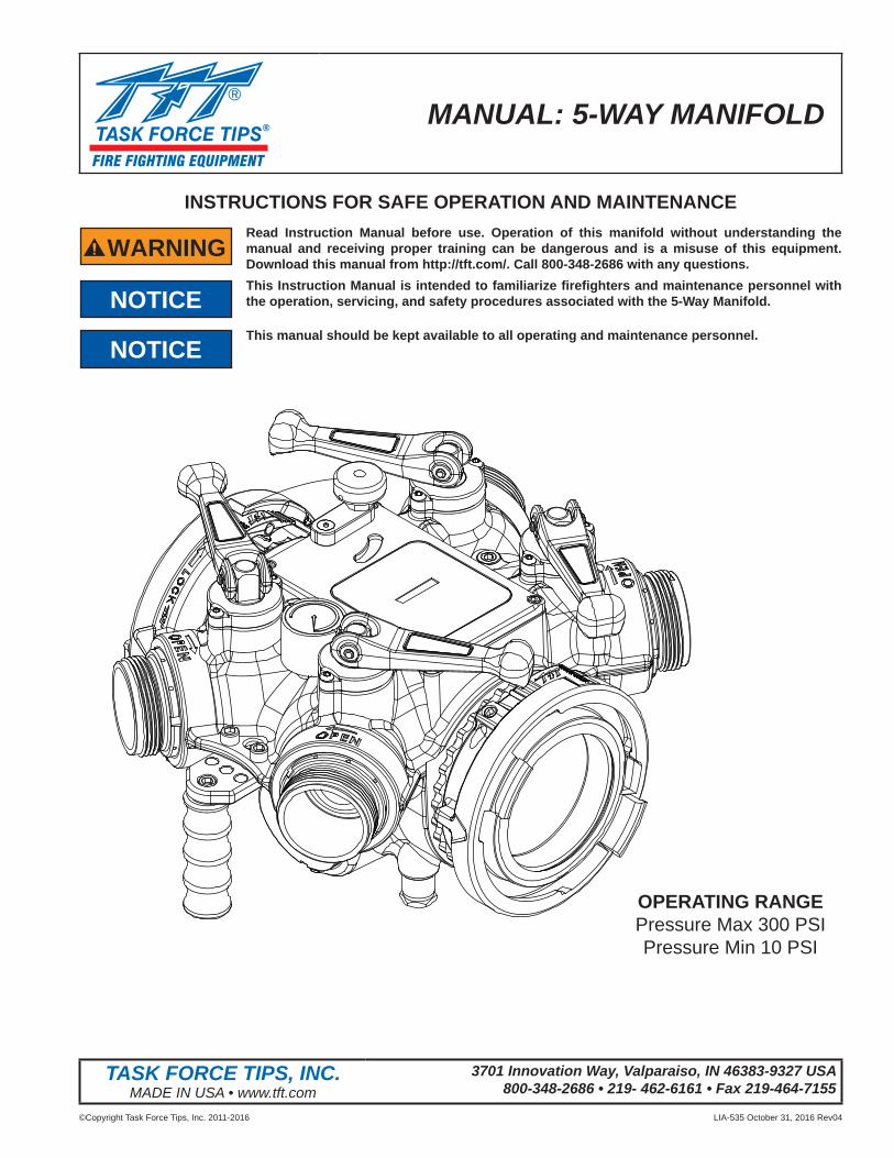
MANUAL: 5-WAY MANIFOLD
INSTRUCTIONS FOR SAFE OPERATION AND MAINTENANCE
WARNINGRead Instruction Manual before use. Operation of this manifold without understanding the manual and receiving proper training can be dangerous and is a misuse of this equipment. Download this manual from http://tft.com/. Call 800-348-2686 with any questions.
NOTICEThis Instruction Manual is intended to familiarize fi refi ghters and maintenance personnel with the operation, servicing, and safety procedures associated with the 5-Way Manifold.
NOTICEThis manual should be kept available to all operating and maintenance personnel.
OPERATING RANGEPressure Max 300 PSIPressure Min 10 PSI
TASK FORCE TIPS, INC.MADE IN USA • www.tft.com
3701 Innovation Way, Valparaiso, IN 46383-9327 USA800-348-2686 • 219- 462-6161 • Fax 219-464-7155
©Copyright Task Force Tips, Inc. 2011-2016 LIA-535 October 31, 2016 Rev042
Table Of Contents1.0 MEANING OF SAFETY SIGNAL WORDS2.0 SAFETY3.0 GENERAL INFORMATION 3.1 VALVE SPECIFICATIONS 3.2 CORROSION 3.3 USE WITH SALT WATER 3.4 LOW TEMPERATURE USE 3.5 AIR FLUSH PORT 3.6 PRESSURE RELIEF VALVE 3.7 VALVE STORAGE BRACKET 3.8 FEATURE IDENTIFICATION 4.0 USE 4.1 INSTALLING AND USING THE MANIFOLD 4.2 PRESSURE LOSS5.0 MAINTENANCE6.0 EXPLODED VIEWS 6.1 MAIN VALVE ASSEMBLY 6.2 MAIN VALVE ASSEMBLY PARTS LIST 6.3 INLET COMPONENTS PARTS LIST 6.4 OUTLET COMPONENTS PARTS LIST 6.5 2.5” VALVE COMPONENTS PARTS LIST7.0 WARRANTY8.0 ANSWERS TO YOUR QUESTIONS
DANGERPERSONAL RESPONSIBILITY CODE
The member companies of FEMSA that provide emergency response equipment and services want responders to know and understand the following:1. Firefi ghting and Emergency Response are inherently dangerous activities
requiring proper training in their hazards and the use of extreme caution at all times.
2. It is your responsibility to read and understand any user’s instructions, including purpose and limitations, provided with any piece of equipment you may be called upon to use.
3. It is your responsibility to know that you have been properly trained in Firefi ghting and /or Emergency Response and in the use, precautions, and care of any equipment you may be called upon to use.
4. It is your responsibility to be in proper physical condition and to maintain the personal skill level required to operate any equipment you may be called upon to use.
5. It is your responsibility to know that your equipment is in operable condition and has been maintained in accordance with the manufacturer’s instructions.
6. Failure to follow these guidelines may result in death, burns or other severe injury.
FEMSA Fire and Emergency Manufacturers and Service AssociationP.O. Box 147, Lynnfi eld, MA 01940 • www.FEMSA.org
©Copyright Task Force Tips, Inc. 2011-2016 LIA-535 October 31, 2016 Rev043
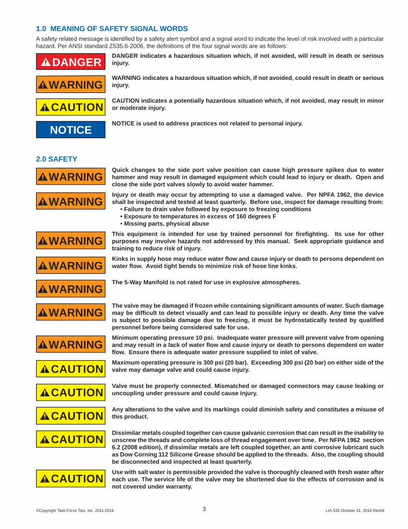
1.0 MEANING OF SAFETY SIGNAL WORDSA safety related message is identifi ed by a safety alert symbol and a signal word to indicate the level of risk involved with a particular hazard. Per ANSI standard Z535.6-2006, the defi nitions of the four signal words are as follows:
DANGERDANGER indicates a hazardous situation which, if not avoided, will result in death or serious injury.
WARNINGWARNING indicates a hazardous situation which, if not avoided, could result in death or serious injury.
CAUTIONCAUTION indicates a potentially hazardous situation which, if not avoided, may result in minor or moderate injury.
NOTICENOTICE is used to address practices not related to personal injury.
2.0 SAFETY
WARNINGQuick changes to the side port valve position can cause high pressure spikes due to water hammer and may result in damaged equipment which could lead to injury or death. Open and close the side port valves slowly to avoid water hammer.
WARNINGInjury or death may occur by attempting to use a damaged valve. Per NPFA 1962, the device shall be inspected and tested at least quarterly. Before use, inspect for damage resulting from: • Failure to drain valve followed by exposure to freezing conditions • Exposure to temperatures in excess of 160 degrees F • Missing parts, physical abuse
WARNINGThis equipment is intended for use by trained personnel for fi refi ghting. Its use for other purposes may involve hazards not addressed by this manual. Seek appropriate guidance and training to reduce risk of injury.
WARNINGKinks in supply hose may reduce water fl ow and cause injury or death to persons dependent on water fl ow. Avoid tight bends to minimize risk of hose line kinks.
WARNINGThe 5-Way Manifold is not rated for use in explosive atmospheres.
WARNINGThe valve may be damaged if frozen while containing signifi cant amounts of water. Such damage may be diffi cult to detect visually and can lead to possible injury or death. Any time the valve is subject to possible damage due to freezing, it must be hydrostatically tested by qualifi ed personnel before being considered safe for use.
WARNINGMinimum operating pressure 10 psi. Inadequate water pressure will prevent valve from opening and may result in a lack of water fl ow and cause injury or death to persons dependent on water fl ow. Ensure there is adequate water pressure supplied to inlet of valve.
CAUTIONMaximum operating pressure is 300 psi (20 bar). Exceeding 300 psi (20 bar) on either side of the valve may damage valve and could cause injury.
CAUTIONValve must be properly connected. Mismatched or damaged connectors may cause leaking or uncoupling under pressure and could cause injury.
CAUTIONAny alterations to the valve and its markings could diminish safety and constitutes a misuse of this product.
CAUTIONDissimilar metals coupled together can cause galvanic corrosion that can result in the inability to unscrew the threads and complete loss of thread engagement over time. Per NFPA 1962 section 6.2 (2008 edition), if dissimilar metals are left coupled together, an anti corrosive lubricant such as Dow Corning 112 Silicone Grease should be applied to the threads. Also, the coupling should be disconnected and inspected at least quarterly.
CAUTIONUse with salt water is permissible provided the valve is thoroughly cleaned with fresh water after each use. The service life of the valve may be shortened due to the effects of corrosion and is not covered under warranty.

©Copyright Task Force Tips, Inc. 2011-2016 LIA-535 October 31, 2016 Rev044
3.0 GENERAL INFORMATIONThe 5-Way Manifold is a compact, portable, low friction-loss valve that can be used in many water distribution applications. The hydraulically actuated slide valve combined with four of TFT’s 2.5” quarter-turn ball valves with folding handles make for the ultimate in versatility. All four 2.5” valves can be used with or without the LDH valve being open. Valve seats are fi eld replaceable, and quarter-turn folding valve handles require low force to move, even under pressure. The automatic valve lock on the 2.5” valves maintain valve position while fl owing at partial openings. Folding handles minimize required storage space. Device includes a pressure gage, PRV, and carrying handle. A polymer bearing ring helps prevents galvanic corrosion on LDH couplings. Storage bracket available.
3.1 VALVE SPECIFICATIONSLength: 16” (406mm)Width: 17.5” (445mm)Height: 11.5” (292mm)Weight: 48lbs (21.8kg)Main LDH Waterway size (at valve seat): 4.5” (114 mm) Side ports (4) waterway: 2.5” (63.5mm)LDH valve meets NFPA 1965 2009 3.3.11.3 Slow-Operating Valve Requirement. (Side discharges do not slow-operate)Minimum Operating Pressure: 10 psi (0.7 Bar) LDH VALVE NOT FOR SUCTION USE.Maximum Operating Pressure: 300 psi (20 bar)Hydrostatic Proof Test Pressure: 900 psi (62 bar)Temperature Rating*: -25°F to 135°F (-32°C to 57°C)*For temperatures below 32°F (0°C), valves must be drained after use to avoid damage. See section 3.4 LOW TEMPERATURE USE
3.2 CORROSIONHose couplings are attached using polymer bearing rings which provides electrical insulation to help prevent galvanic corrosion. The valve body is hard anodized, and powder coated to help prevent corrosion. The effects of corrosion can be minimized by good maintenance practice. See section 3.5 AIR FLUSH PORT & 5.0 MAINTENANCE.
3.3 USE WITH SALT WATERUse with salt water is permissible provided valve is thoroughly cleaned with fresh water after each use. The service life of the valve may be shortened due to the effects of corrosion and is not covered under warranty.
3.4 LOW TEMPERATURE USEThe valve is designed with self-draining waterways. In extreme freezing conditions, extra precautions should be taken to ensure control waterways remain free from ice. Residual water should be cleared from the valve after each use. See section 3.5 AIR FLUSH PORT.
3.5 AIR FLUSH PORTThe valve is equipped with an air fl ush port. Remove the cap. Use a Schrader air chuck to apply a minimum of 20 psi (1.4 bar) to the air fl ush port. Open and close the control valve. Residual water will be forced out through the fi lter and control valve bleed drain.
CAUTIONThe sliding plug is pinch hazard that can cause injury. Keep hands and fi ngers outside of the valve any time air is applied to air fl ush port.
3.6 PRESSURE RELIEF VALVELDH valved appliances may be equipped with a pressure relief valve that can be set to any pressure between 50 and 200 psi. Its function is to protect the pump and supply hose from excess pressure. See LIA-202 PRESSURE RELIEF VALVE INSTRUCTIONS FOR SAFE OPERATION AND MAINTENANCE.
3.7 VALVE STORAGE BRACKETA storage bracket is available for the 5-Way Manifold. The valve can be stored with hose pre-connected to the inlet and/or outlet of the valve. The storage bracket can be mounted vertically or horizontally with the included self-tapping stainless steel screws. The bracket requires 12.5” x 11.1” (317.5mm x 281.9mm) of panel space. To purchase a bracket, order TFT part number AU-BRACKET.

©Copyright Task Force Tips, Inc. 2011-2016 LIA-535 October 31, 2016 Rev045
3.8 FEATURE IDENTIFICATION
LDH VALVE HANDLE
FLOWDIRECTION
INLET
PRESSURE RELIEF VALVE
PRESSURE GAUGE
SIDEDISCHARGE
PORT
AIR FLUSH PORT
CONTROL VALVE
CONTROLVALVE FILTER
SERIAL NUMBER
MODEL NUMBER
2.5" VALVE HANDLES
OUTLET
WARNING
SLIDING PLUG
CONTROL VALVEBLEED DRAIN
SIDEDISCHARGEPORT

©Copyright Task Force Tips, Inc. 2011-2016 LIA-535 October 31, 2016 Rev046
4.0 USE4.1 INSTALLING AND USING THE MANIFOLD
Make connections to each port to be used.
Ensure that fl ow will move in the direction indicated on the valve.
WARNINGValve will not properly open or close if fl ow direction does not match arrow printed on exterior of valve. Reducing or interrupting of fl ow may cause injury or death to persons dependent on water fl ow.
FLOW DIRECTION
Verify that all discharge ports are closed by rotating all valve handles to the CLOSED position.
Pressurize manifold.
CAUTIONPressurizing manifold with discharge ports open can cause injury by unintentionally charging hose lines. Open ports as needed.
When fl ow from the LDH discharge port is required, rotate the handle clockwise to the fi rst position for a slower opening speed, or to the second position for a normal opening speed. LDH valve handle opens control valve, allowing water pressure to build in control chamber and move sliding plug fully open. Both positions meet NFPA slow operating requirements. Rapid changes to handle position will not defeat the slow-operating feature.
WARNINGMinimum operating pressure 10 psi. Inadequate water pressure will prevent valve from opening and may result in a lack of water fl ow and cause injury or death to persons dependent on water fl ow. Ensure there is adequate water pressure supplied to inlet of valve.
Valve Handle in Closed Position
Valve handle in Slow Open Position
Valve handle in Normal Open Position
To stop fl ow from the LDH valve discharge port, rotate the LDH valve handle to the closed position. LDH valve handle closes control valve, allowing water from control chamber to drain to ground and slowly close sliding plug.
Valve handle in closed position

©Copyright Task Force Tips, Inc. 2011-2016 LIA-535 October 31, 2016 Rev047
4.2 PRESSURE LOSS
0.0
2.0
4.0
6.0
8.0
10.0
12.0
14.0
16.0
18.0
20.0
0 200 400 600 800 1000 1200 1400 1600 1800 2000
LOSS
(PSI
)
FLOW (GPM)
Main Waterway 2.5" Port
5.0 MAINTENANCEThis valve should be disconnected, cleaned and visually inspected inside and out at least quarterly for proper function per NFPA 1962 2008 Section 8.2, or as water quality and use may require. Moving parts should be checked for smooth and free operation. Seals shall be greased as needed with silicone-based grease such as Dow Corning 112. Any scrapes that expose bare aluminum should be cleaned and touched up with enamel paint such as Rust-Oleum. Keys point of inspection:
• There is no damage such as cracks or dents• There is no corrosion• The waterway is clear of obstructions
• The sliding plug moves freely (Use Air Flush Port to test according to section 3.5 AIR FLUSH PORT)Replace any missing or damaged parts before returning to service. Any repaired device must be tested before being placed in service.
CAUTION Any alterations to the device and its markings could diminish safety and constitute a misuse this product.

©Copyright Task Force Tips, Inc. 2011-2016 LIA-535 October 31, 2016 Rev048
6.0 EXPLODED VIEWS6.1 MAIN VALVE ASSEMBLY
1514
1213
2018
1716
19
44
7
23
54
68
910
11
5143
44
24
25
474645
38
24
37363326 2927 28 34 3530 31 32
39 2221
23
40 41 42
32
49
52
5048
1
©Copyright Task Force Tips, Inc. 2011-2016 LIA-535 October 31, 2016 Rev049
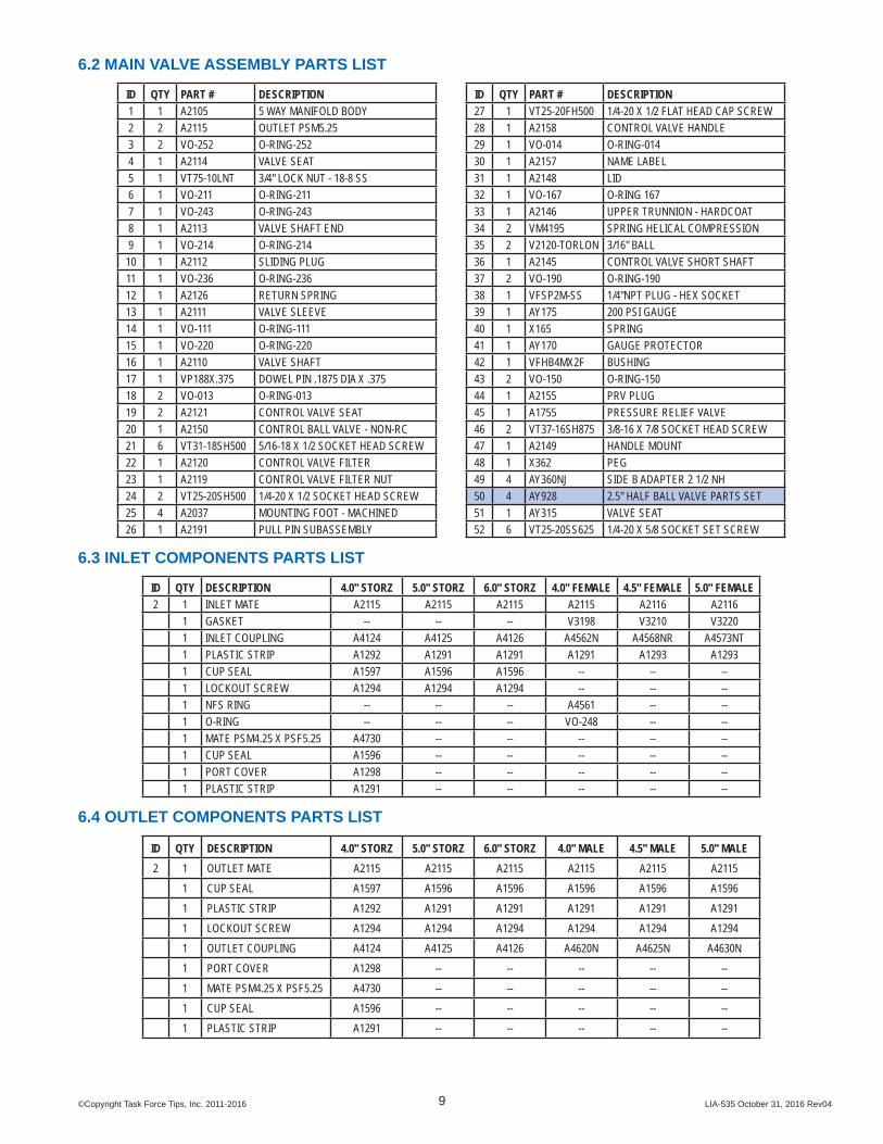
6.2 MAIN VALVE ASSEMBLY PARTS LIST
ID QTY PART # DESCRIPTION ID QTY PART # DESCRIPTION1 1 A2105 5 WAY MANIFOLD BODY 27 1 VT25-20FH500 1/4-20 X 1/2 FLAT HEAD CAP SCREW2 2 A2115 OUTLET PSM5.25 28 1 A2158 CONTROL VALVE HANDLE3 2 VO-252 O-RING-252 29 1 VO-014 O-RING-0144 1 A2114 VALVE SEAT 30 1 A2157 NAME LABEL5 1 VT75-10LNT 3/4" LOCK NUT - 18-8 SS 31 1 A2148 LID6 1 VO-211 O-RING-211 32 1 VO-167 O-RING 1677 1 VO-243 O-RING-243 33 1 A2146 UPPER TRUNNION - HARDCOAT8 1 A2113 VALVE SHAFT END 34 2 VM4195 SPRING HELICAL COMPRESSION9 1 VO-214 O-RING-214 35 2 V2120-TORLON 3/16" BALL10 1 A2112 SLIDING PLUG 36 1 A2145 CONTROL VALVE SHORT SHAFT11 1 VO-236 O-RING-236 37 2 VO-190 O-RING-19012 1 A2126 RETURN SPRING 38 1 VFSP2M-SS 1/4"NPT PLUG - HEX SOCKET13 1 A2111 VALVE SLEEVE 39 1 AY175 200 PSI GAUGE14 1 VO-111 O-RING-111 40 1 X165 SPRING15 1 VO-220 O-RING-220 41 1 AY170 GAUGE PROTECTOR16 1 A2110 VALVE SHAFT 42 1 VFHB4MX2F BUSHING17 1 VP188X.375 DOWEL PIN .1875 DIA X .375 43 2 VO-150 O-RING-15018 2 VO-013 O-RING-013 44 1 A2155 PRV PLUG19 2 A2121 CONTROL VALVE SEAT 45 1 A1755 PRESSURE RELIEF VALVE20 1 A2150 CONTROL BALL VALVE - NON-RC 46 2 VT37-16SH875 3/8-16 X 7/8 SOCKET HEAD SCREW21 6 VT31-18SH500 5/16-18 X 1/2 SOCKET HEAD SCREW 47 1 A2149 HANDLE MOUNT22 1 A2120 CONTROL VALVE FILTER 48 1 X362 PEG23 1 A2119 CONTROL VALVE FILTER NUT 49 4 AY360NJ SIDE B ADAPTER 2 1/2 NH24 2 VT25-20SH500 1/4-20 X 1/2 SOCKET HEAD SCREW 50 4 AY928 2.5" HALF BALL VALVE PARTS SET 25 4 A2037 MOUNTING FOOT - MACHINED 51 1 AY315 VALVE SEAT26 1 A2191 PULL PIN SUBASSEMBLY 52 6 VT25-20SS625 1/4-20 X 5/8 SOCKET SET SCREW
6.3 INLET COMPONENTS PARTS LIST
ID QTY DESCRIPTION 4.0" STORZ 5.0" STORZ 6.0" STORZ 4.0" FEMALE 4.5" FEMALE 5.0" FEMALE2 1 INLET MATE A2115 A2115 A2115 A2115 A2116 A2116
1 GASKET -- -- -- V3198 V3210 V32201 INLET COUPLING A4124 A4125 A4126 A4562N A4568NR A4573NT1 PLASTIC STRIP A1292 A1291 A1291 A1291 A1293 A12931 CUP SEAL A1597 A1596 A1596 -- -- --1 LOCKOUT SCREW A1294 A1294 A1294 -- -- --1 NFS RING -- -- -- A4561 -- --1 O-RING -- -- -- VO-248 -- --1 MATE PSM4.25 X PSF5.25 A4730 -- -- -- -- --1 CUP SEAL A1596 -- -- -- -- --1 PORT COVER A1298 -- -- -- -- --1 PLASTIC STRIP A1291 -- -- -- -- --
6.4 OUTLET COMPONENTS PARTS LIST
ID QTY DESCRIPTION 4.0" STORZ 5.0" STORZ 6.0" STORZ 4.0" MALE 4.5" MALE 5.0" MALE2 1 OUTLET MATE A2115 A2115 A2115 A2115 A2115 A2115
1 CUP SEAL A1597 A1596 A1596 A1596 A1596 A15961 PLASTIC STRIP A1292 A1291 A1291 A1291 A1291 A12911 LOCKOUT SCREW A1294 A1294 A1294 A1294 A1294 A12941 OUTLET COUPLING A4124 A4125 A4126 A4620N A4625N A4630N
1 PORT COVER A1298 -- -- -- -- -- 1 MATE PSM4.25 X PSF5.25 A4730 -- -- -- -- -- 1 CUP SEAL A1596 -- -- -- -- -- 1 PLASTIC STRIP A1291 -- -- -- -- --
©Copyright Task Force Tips, Inc. 2011-2016 LIA-535 October 31, 2016 Rev0410
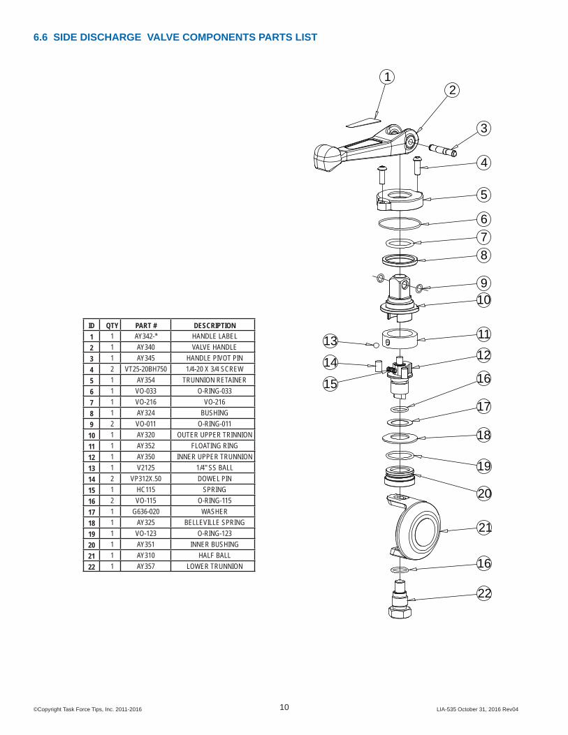
6.6 SIDE DISCHARGE VALVE COMPONENTS PARTS LIST
7
12
11
109
8
6
5
4
13
15
14
21
3
16
17
18
19
20
21
16
22
ID QTY PART # DESCRIPTION1 1 AY342-* HANDLE LABEL2 1 AY340 VALVE HANDLE3 1 AY345 HANDLE PIVOT PIN4 2 VT25-20BH750 1/4-20 X 3/4 SCREW5 1 AY354 TRUNNION RETAINER6 1 VO-033 O-RING-0337 1 VO-216 VO-2168 1 AY324 BUSHING9 2 VO-011 O-RING-011
10 1 AY320 OUTER UPPER TRINNION11 1 AY352 FLOATING RING12 1 AY350 INNER UPPER TRUNNION13 1 V2125 1/4" SS BALL14 2 VP312X.50 DOWEL PIN15 1 HC115 SPRING16 2 VO-115 O-RING-11517 1 G636-020 WASHER18 1 AY325 BELLEVILLE SPRING19 1 VO-123 O-RING-12320 1 AY351 INNER BUSHING21 1 AY310 HALF BALL22 1 AY357 LOWER TRUNNION
©Copyright Task Force Tips, Inc. 2011-2016 LIA-535 October 31, 2016 Rev0411
7.0 WARRANTYTask Force Tips, Inc., 3701 Industrial Way, Valparaiso, Indiana 46383-9327 USA (“TFT”) warrants to the original purchaser of its 5-WAY MANIFOLD (“equipment”), and to anyone to whom it is transferred, that the equipment shall be free from defects in material and workmanship during the fi ve (5) year period from the date of purchase.TFT’s obligation under this warranty is specifi cally limited to replacing or repairing the equipment (or its parts) which are shown by TFT’s examination to be in a defective condition attributable to TFT. To qualify for this limited warranty, the claimant must return the equipment to TFT, at 3701 Industrial Way, Valparaiso, Indiana 46383-9327 USA, within a reasonable time after discovery of the defect. TFT will examine the equipment. If TFT determines that there is a defect attributable to it, TFT will correct the problem within a reasonable time. If the equipment is covered by this limited warranty, TFT will assume the expenses of repair.If any defect attributable to TFT under this limited warranty cannot be reasonably cured by repair or replacement, TFT may elect to refund the purchase price of the equipment, less reasonable depreciation, in complete discharge of its obligations under this limited warranty. If TFT makes this election, claimant shall return the equipment to TFT free and clear of any liens and encumbrances.This is a limited warranty. The original purchaser of the equipment, any person to whom it is transferred, and any person who is an intended or unintended benefi ciary of the equipment, shall not be entitled to recover from TFT any consequential or incidental damages for injury to person and/or property resulting from any defective equipment manufactured or assembled by TFT. It is agreed and understood that the price stated for the equipment is in part consideration for limiting TFT’s liability. Some states do not allow the exclusion or limitation of incidental or consequential damages, so the above may not apply to you.TFT shall have no obligation under this limited warranty if the equipment is, or has been, misused or neglected (including failure to provide reasonable maintenance) or if there have been accidents to the equipment or if it has been repaired or altered by someone else.THIS IS A LIMITED EXPRESS WARRANTY ONLY. TFT EXPRESSLY DISCLAIMS WITH RESPECT TO THE EQUIPMENT ALL IMPLIED WARRANTIES OF MERCHANTABILITY AND ALL IMPLIED WARRANTIES OF FITNESS FOR A PARTICULAR PURPOSE. THERE IS NO WARRANTY OF ANY NATURE MADE BY TFT BEYOND THAT STATED IN THIS DOCUMENT.This limited warranty gives you specifi c legal rights, and you may also have other rights which vary from state to state.
8.0 ANSWERS TO YOUR QUESTIONSWe appreciate the opportunity of serving you and making your job easier. If you have any problems or questions, our toll-free “Hydraulics Hotline”, 800-348-2686, is normally available to you 24 hours a day, 7 days a week.

©Copyright Task Force Tips, Inc. 2011-2016 LIA-535 October 31, 2016 Rev04
TASK FORCE TIPS, INC.MADE IN USA • www.tft.com
3701 Innovation Way, Valparaiso, IN 46383-9327 USA800-348-2686 • 219- 462-6161 • Fax 219-464-7155