Manual 1 - FWT
37
OPERATIONS AND PROGRAMMING MANUAL MODEL 5085 MERIDIAN NEUTRON SURVEY METER November 2000 Health Physics Instruments 330 D South Kellogg Ave. Goleta, CA 93117
Transcript of Manual 1 - FWT
OPERATIONS AND
PROGRAMMING MANUAL
MODEL 5085
MERIDIAN NEUTRON SURVEY METER
November 2000
Health Physics Instruments
330 D South Kellogg Ave. Goleta, CA 93117
MODEL 5085 MERIDIAN Health Physics Instruments i
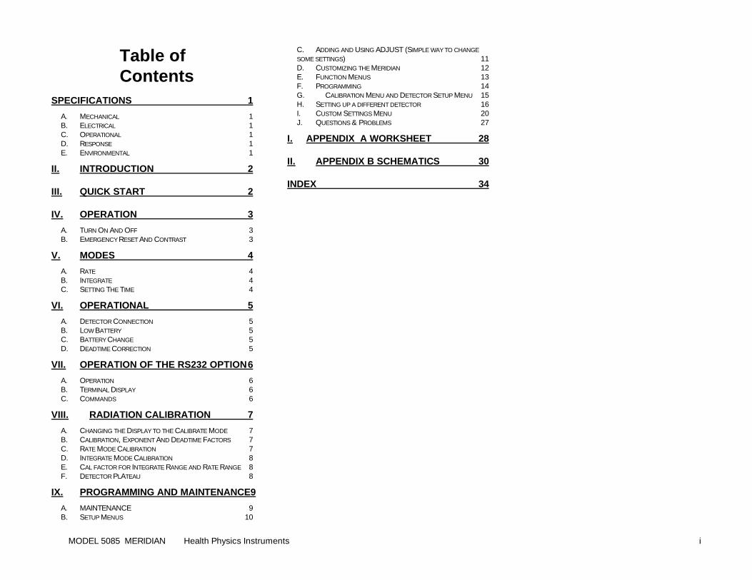
Table of Contents
SPECIFICATIONS 1 A. MECHANICAL 1 B. ELECTRICAL 1 C. OPERATIONAL 1 D. RESPONSE 1 E. ENVIRONMENTAL 1
II. INTRODUCTION 2
III. QUICK START 2
IV. OPERATION 3 A. TURN ON AND OFF 3 B. EMERGENCY RESET AND CONTRAST 3
V. MODES 4 A. RATE 4 B. INTEGRATE 4 C. SETTING THE TIME 4
VI. OPERATIONAL 5 A. DETECTOR CONNECTION 5 B. LOW BATTERY 5 C. BATTERY CHANGE 5 D. DEADTIME CORRECTION 5
VII. OPERATION OF THE RS232 OPTION 6 A. OPERATION 6 B. TERMINAL DISPLAY 6 C. COMMANDS 6
VIII. RADIATION CALIBRATION 7 A. CHANGING THE DISPLAY TO THE CALIBRATE MODE 7 B. CALIBRATION, EXPONENT AND DEADTIME FACTORS 7 C. RATE MODE CALIBRATION 7 D. INTEGRATE MODE CALIBRATION 8 E. CAL FACTOR FOR INTEGRATE RANGE AND RATE RANGE 8 F. DETECTOR PLATEAU 8
IX. PROGRAMMING AND MAINTENANCE9 A. MAINTENANCE 9 B. SETUP MENUS 10
C. ADDING AND USING ADJUST (SIMPLE WAY TO CHANGE SOME SETTINGS) 11 D. CUSTOMIZING THE MERIDIAN 12 E. FUNCTION MENUS 13 F. PROGRAMMING 14 G. CALIBRATION MENU AND DETECTOR SETUP MENU 15 H. SETTING UP A DIFFERENT DETECTOR 16 I. CUSTOM SETTINGS MENU 20 J. QUESTIONS & PROBLEMS 27
I. APPENDIX A WORKSHEET 28
II. APPENDIX B SCHEMATICS 30
INDEX 34
MODEL 5085 MERIDIAN Health Physics Instruments 1
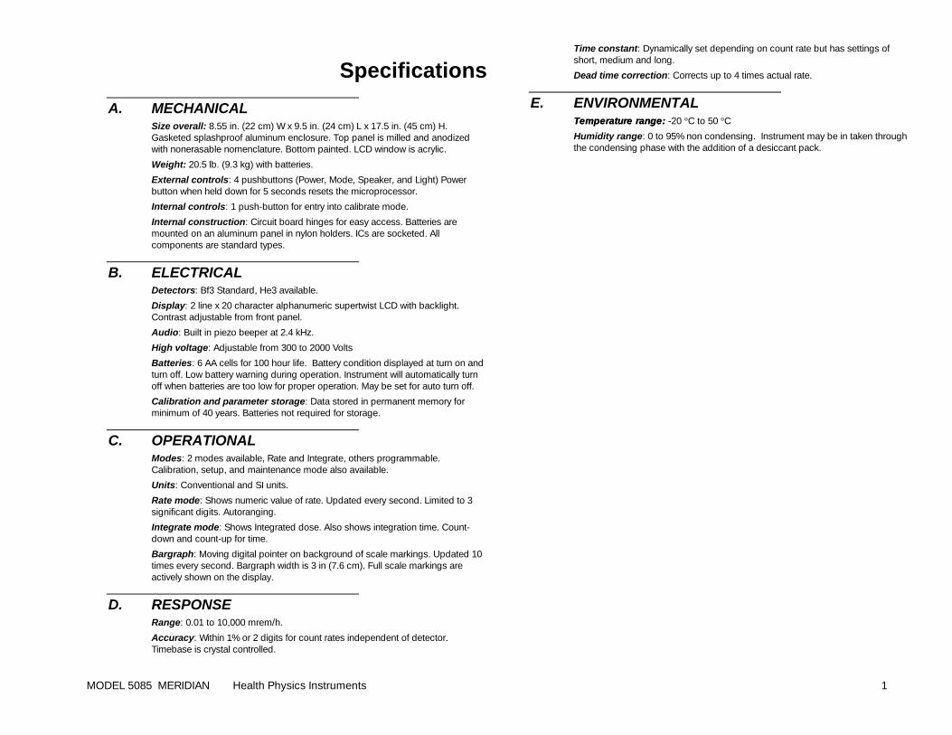
Specifications
A. MECHANICAL Size overall: 8.55 in. (22 cm) W x 9.5 in. (24 cm) L x 17.5 in. (45 cm) H. Gasketed splashproof aluminum enclosure. Top panel is milled and anodized with nonerasable nomenclature. Bottom painted. LCD window is acrylic.
Weight: 20.5 lb. (9.3 kg) with batteries.
External controls: 4 pushbuttons (Power, Mode, Speaker, and Light) Power button when held down for 5 seconds resets the microprocessor.
Internal controls: 1 push-button for entry into calibrate mode.
Internal construction: Circuit board hinges for easy access. Batteries are mounted on an aluminum panel in nylon holders. ICs are socketed. All components are standard types.
B. ELECTRICAL Detectors: Bf3 Standard, He3 available.
Display: 2 line x 20 character alphanumeric supertwist LCD with backlight. Contrast adjustable from front panel.
Audio: Built in piezo beeper at 2.4 kHz.
High voltage: Adjustable from 300 to 2000 Volts
Batteries: 6 AA cells for 100 hour life. Battery condition displayed at turn on and turn off. Low battery warning during operation. Instrument will automatically turn off when batteries are too low for proper operation. May be set for auto turn off.
Calibration and parameter storage: Data stored in permanent memory for minimum of 40 years. Batteries not required for storage.
C. OPERATIONAL Modes: 2 modes available, Rate and Integrate, others programmable. Calibration, setup, and maintenance mode also available.
Units: Conventional and SI units.
Rate mode: Shows numeric value of rate. Updated every second. Limited to 3 significant digits. Autoranging.
Integrate mode: Shows Integrated dose. Also shows integration time. Count-down and count-up for time.
Bargraph: Moving digital pointer on background of scale markings. Updated 10 times every second. Bargraph width is 3 in (7.6 cm). Full scale markings are actively shown on the display.
D. RESPONSE Range: 0.01 to 10,000 mrem/h.
Accuracy: Within 1% or 2 digits for count rates independent of detector. Timebase is crystal controlled.
Time constant: Dynamically set depending on count rate but has settings of short, medium and long.
Dead time correction: Corrects up to 4 times actual rate.
E. ENVIRONMENTAL Temperature range:Temperature range: -20 °C to 50 °C
Humidity range: 0 to 95% non condensing. Instrument may be in taken through the condensing phase with the addition of a desiccant pack.
MODEL 5085 MERIDIAN Health Physics Instruments 2
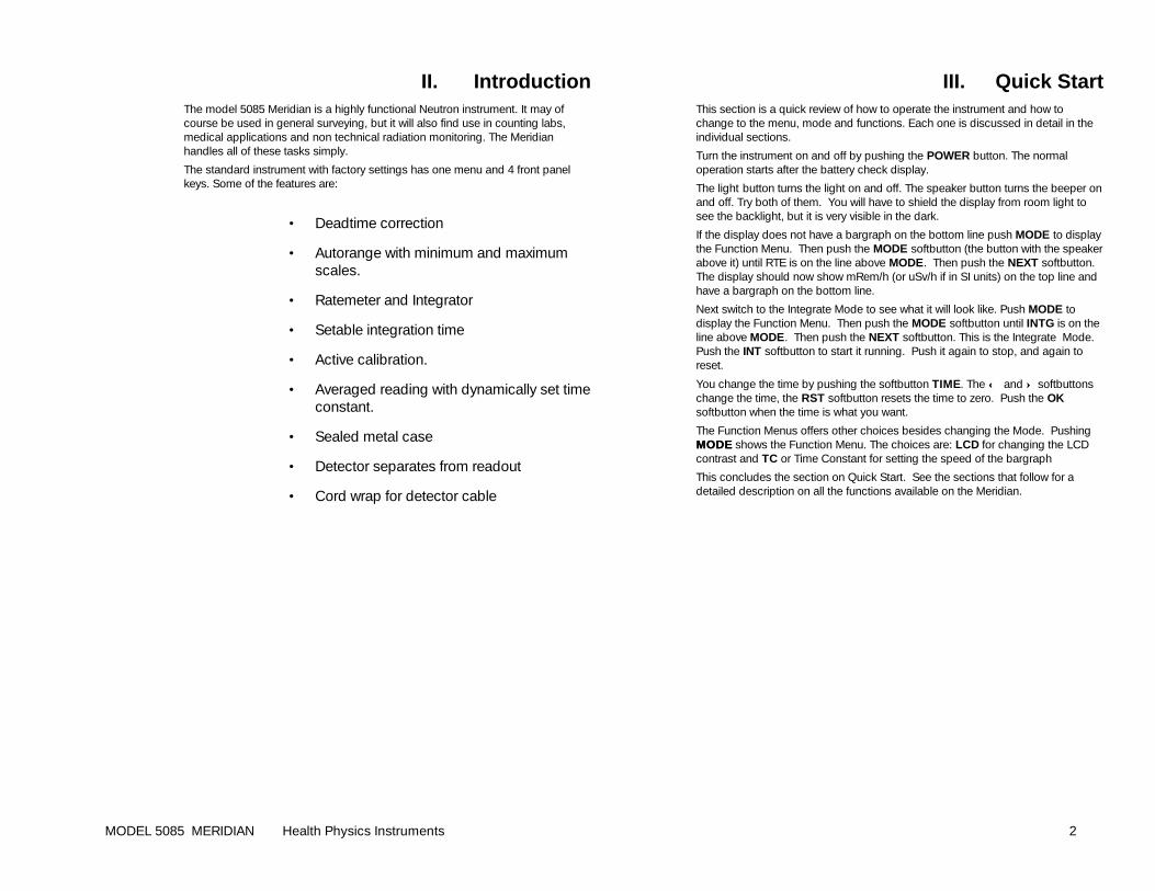
II. Introduction The model 5085 Meridian is a highly functional Neutron instrument. It may of course be used in general surveying, but it will also find use in counting labs, medical applications and non technical radiation monitoring. The Meridian handles all of these tasks simply.
The standard instrument with factory settings has one menu and 4 front panel keys. Some of the features are:
• Deadtime correction
• Autorange with minimum and maximum scales.
• Ratemeter and Integrator
• Setable integration time
• Active calibration.
• Averaged reading with dynamically set time constant.
• Sealed metal case
• Detector separates from readout
• Cord wrap for detector cable
III. Quick Start This section is a quick review of how to operate the instrument and how to change to the menu, mode and functions. Each one is discussed in detail in the individual sections.
Turn the instrument on and off by pushing the POWER button. The normal operation starts after the battery check display.
The light button turns the light on and off. The speaker button turns the beeper on and off. Try both of them. You will have to shield the display from room light to see the backlight, but it is very visible in the dark.
If the display does not have a bargraph on the bottom line push MODE to display the Function Menu. Then push the MODE softbutton (the button with the speaker above it) until RTE is on the line above MODE. Then push the NEXT softbutton. The display should now show mRem/h (or uSv/h if in SI units) on the top line and have a bargraph on the bottom line.
Next switch to the Integrate Mode to see what it will look like. Push MODE to display the Function Menu. Then push the MODE softbutton until INTG is on the line above MODE. Then push the NEXT softbutton. This is the Integrate Mode. Push the INT softbutton to start it running. Push it again to stop, and again to reset.
You change the time by pushing the softbutton TIME. The ←← and ↑↑ softbuttons change the time, the RST softbutton resets the time to zero. Push the OK softbutton when the time is what you want.
The Function Menus offers other choices besides changing the Mode. Pushing MODEMODE shows the Function Menu. The choices are: LCD for changing the LCD contrast and TC or Time Constant for setting the speed of the bargraph
This concludes the section on Quick Start. See the sections that follow for a detailed description on all the functions available on the Meridian.
MODEL 5085 MERIDIAN Health Physics Instruments 3
IV. Operation
A. TURN ON AND OFF The Meridian is easy to turn on, just push the POWER button. Pushing it once will turn the instrument on and pushing it again will turn the instrument off. The first display will show the version number of the software, 4 places of user text, and the hours remaining on the battery. Then the instrument will go into normal operation.
If the batteries are too weak it will not turn on. If it tries to turn on and immediately turns off, it may also be due to weak batteries. The instrument will automatically turn off whenever the batteries are too weak to power the instrument.
If the instrument detects a fault in the memory, it will show FAILURE #1 in the display. If this occurs see the section on Maintenance.
The turn off display shows the hours remaining on the batteries. If the instrument has less than 8 hours, it will beep three times to indicate that the batteries should be changed.
B. EMERGENCY RESET AND CONTRAST If the batteries are good and the instrument will not turn on, it is possible that the instrument is actually turning on but the contrast is set too light or dark. To do an emergency contrast setting, turn the instrument on while holding down the speaker button. Wait 2 seconds then release the button. Then hold down the speaker button if the display is too light. If the display is too dark, then hold down the light button. Continue to hold the button down until the display shows a normal contrast and the contrast menu. Then push the NEXT softbutton to resume normal operation.
The instrument can be reset by holding down the POWER button for 10 seconds or until the display blanks, then releasing it. This is a cold start for the microprocessor. It will reset the instrument which should then show the turn on display. This can be done at any time to reset the instrument and is the same as turning it off then back on.
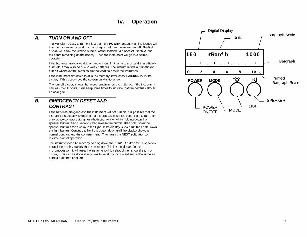
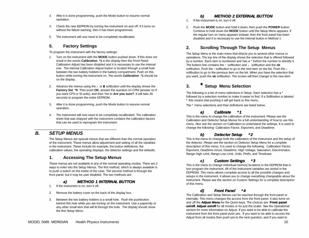
150 mRem/h 1000
! . . . ! . . . ! . . . ! . . . ! . . . ! .
0 2 4 6 8 10
POWER MODE
SPEAKER
LIGHT POWER ON/OFF MODE
Digital Display
Units Bargraph Scale
Bargraph
Printed Bargraph Scale
MODEL 5085 MERIDIAN Health Physics Instruments 4
V. Modes Below is a description of the different modes. Change between the modes by using the MODE softbutton (the button below the speaker symbol) in the Function Menu. Press MODE to view the Function Menu.
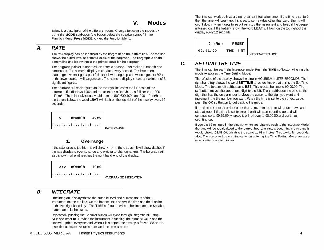
A. RATE The rate display can be identified by the bargraph on the bottom line. The top line shows the digital level and the full scale of the bargraph. The bargraph is on the bottom line and below that is the printed scale for the bargraph.
The bargraph pointer is updated ten times a second. This makes it smooth and continuous. The numeric display is updated every second. The instrument autoranges; when it goes past full scale it will range up and when it gets to 80% of the lower scale, it will range down. The numeric display shows a maximum of 3 significant figures.
The bargraph full scale figure on the top right indicates the full scale of the bargraph. If it displays 1000 and the units are mRem/h, then full scale is 1000 mRem/h. The minor divisions would then be 800,600,400, and 200 mRem/h. If the battery is low, the word LBAT will flash on the top right of the display every 12 seconds.
0 mRem/h 1000
! . . . ! . . . ! . . . ! . . . ! . . . ! RATE RANGE
1. Overrange If the rate value is too high, it will show >>> in the display. It will show dashes if the rate display is over its range and waiting to change ranges. The bargraph will also show > when it reaches the right hand end of the display.
>>> mRem/h 1000
! . . . ! . . . ! . . . ! . . . ! . . . ! OVERRANGE INDICATION
B. INTEGRATE The integrate display shows the numeric level and current status of the instrument on the top line. On the bottom line it shows the time and the function of the two right hand keys. The TIME softbutton will set the time and the Speaker button controls the status.
Repeatedly pushing the Speaker button will cycle through integrate INT, stop STP and reset RST. When the instrument is running, the numeric value and the time will update every second When it is stopped the display is frozen. When it is reset the integrated value is reset and the time is preset.
The time can work both as a timer or as an integration timer. If the time is set to 0, then the timer will count up. If it is set to some value other than zero, then it will count down; when it gets to zero it will stop the instrument and beep if the beeper is turned on. If the battery is low, the word LBAT will flash on the top right of the display every 12 seconds.
0 nRem RESET
00: 01: 00 TME I NT INTEGRATE RANGE
C. SETTING THE TIME The time can be set in the integrate mode. Push the TIME softbutton when in this mode to access the Time Setting Mode.
The left side of the display shows the time in HOURS:MINUTES:SECONDS. The right hand top shows the word SETTIME to let you know that this is the Set Time Mode. The bottom left softbutton is RST. This resets the time to 00:00:00. The ←← softbutton moves the cursor one digit to the left. The ↑↑ softbutton increments the digit that has the cursor under it. Move the cursor to the digit you want and increment it to the number you want. When the time is set to the correct value, push the OK softbutton to get back to the mode.
If the time is set to a number other than zero, then the time will count down and stop at zero. If the time is set to zero, then it will start counting up and will continue up to 99:59:59 whereby it will roll over to 00:00:00 and continue counting up.
If you set 68 minutes in the display, when you change back to the Integrate Mode, the time will be recalculated to the correct hours: minutes: seconds. In this case it would show: 01:08:00, which is the same as 68 minutes. This works for seconds also. The cursor will be on minutes when entering the Time Setting Mode because most settings are in minutes
MODEL 5085 MERIDIAN Health Physics Instruments 5
VI. Operational
A. DETECTOR CONNECTION The detector is connected to the instrument through the MHV located on the top panel.
B. LOW BATTERY When the battery is low and has less than 8 hours remaining, the word LBAT flashes in the upper right hand corner. It flashes every 12 seconds. It does not flash in the Function Menus.
C. BATTERY CHANGE When the batteries are too low as indicated on the turn on menu, or the turn off menu, then it is time to change them. The instrument uses 6 type AA “penlight” (ANSI L40 IEC LR6) cells. These can be any type of battery except lithium. (If you want to use lithium, use 3 ea. 3 volt lithium AA cells and 3 dummy AA batteries). The hours that are displayed at turn on and turn off are calculated for alkaline batteries. Carbon-zinc batteries will not give the correct time.
The batteries are located inside the instrument. Access is by removing the bottom case. To change the batteries, remove the bottom of the enclosure by twisting the twist-lock connectors on each end of the instrument counter-clockwise. This should release the bottom of the instrument. Remove it and turn the instrument over. There are the 6 AA cells. Remove the existing batteries, and replace them with new ones. Replace the bottom of the enclosure.
If the batteries have leaked into the bottom of the instrument, wash the case bottom thoroughly with soapy water, then with clear water. Dry it and replace it on the instrument. Do not wash the circuit board. The battery holders may need to be cleaned with a dampened cloth or sponge.
D. DEADTIME CORRECTION The Factory settings turn on the deadtime correction in the Rate Mode, and the Integrate Mode.
MODEL 5085 MERIDIAN Health Physics Instruments 6
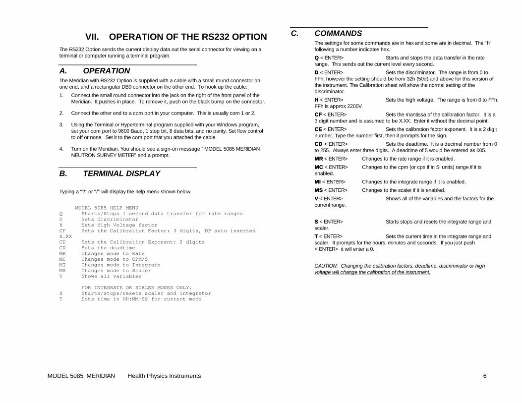
VII. OPERATION OF THE RS232 OPTION The RS232 Option sends the current display data out the serial connector for viewing on a terminal or computer running a terminal program.
A. OPERATION The Meridian with RS232 Option is supplied with a cable with a small round connector on one end, and a rectangular DB9 connector on the other end. To hook up the cable:
1. Connect the small round connector into the jack on the right of the front panel of the Meridian. It pushes in place. To remove it, push on the black bump on the connector.
2. Connect the other end to a com port in your computer. This is usually com 1 or 2.
3. Using the Terminal or Hyperterminal program supplied with your Windows program, set your com port to 9600 Baud, 1 stop bit, 8 data bits, and no parity. Set flow control to off or none. Set it to the com port that you attached the cable.
4. Turn on the Meridian. You should see a sign-on message “'MODEL 5085 MERIDIAN NEUTRON SURVEY METER” and a prompt.
B. TERMINAL DISPLAY
Typing a “?” or “/” will display the help menu shown below.
MODEL 5085 HELP MENU Q Starts/Stops 1 second data transfer for rate ranges D Sets discriminator H Sets High Voltage factor CF Sets the Calibration Factor: 3 digits, DP auto inserted X.XX CE Sets the Calibration Exponent: 2 digits CD Sets the deadtime MR Changes mode to Rate MC Changes mode to CPM/S MI Changes mode to Integrate MS Changes mode to Scaler V Shows all variables FOR INTEGRATE OR SCALER MODES ONLY. S Starts/stops/resets scaler and integrator T Sets time in HH:MM:SS for current mode
C. COMMANDS The settings for some commands are in hex and some are in decimal. The “h” following a number indicates hex.
QQ <ENTER> Starts and stops the data transfer in the rate range. This sends out the current level every second.
DD <ENTER> Sets the discriminator. The range is from 0 to FFh, however the setting should be from 32h (50d) and above for this version of the instrument. The Calibration sheet will show the normal setting of the discriminator.
HH <ENTER> Sets the high voltage. The range is from 0 to FFh. FFh is approx 2200V.
CFCF <ENTER> Sets the mantissa of the calibration factor. It is a 3 digit number and is assumed to be X.XX. Enter it without the decimal point.
CECE <ENTER> Sets the calibration factor exponent. It is a 2 digit number. Type the number first, then it prompts for the sign.
CD CD <ENTER> Sets the deadtime. It is a decimal number from 0 to 255. Always enter three digits. A deadtime of 5 would be entered as 005.
MRMR <ENTER> Changes to the rate range if it is enabled.
MCMC <ENTER> Changes to the cpm (or cps if in SI units) range if it is enabled.
MIMI <ENTER> Changes to the integrate range if it is enabled.
MSMS <ENTER> Changes to the scaler if it is enabled.
VV <ENTER> Shows all of the variables and the factors for the current range.
SS <ENTER> Starts stops and resets the integrate range and scaler.
TT <ENTER> Sets the current time in the integrate range and scaler. It prompts for the hours, minutes and seconds. If you just push <ENTER> it will enter a 0.
CAUTION: Changing the calibration factors, deadtime, discriminator or high voltage will change the calibration of the instrument.
MODEL 5085 MERIDIAN Health Physics Instruments 7
VIII. Radiation Calibration The instrument is calibrated digitally. There are no trimmers to adjust. The values that adjust the calibration are stored in EEPROM memory for 40 years.
There are two adjustments for each detector that effect the calibration. The instrument is adjusted by changing the calibration factor with exponent, and the deadtime. The Rate Mode and the Integrate Mode need to be calibrated. Changing The Display To Calibrate Mode
A. CHANGING THE DISPLAY TO THE CALIBRATE MODE
1. Turn on the instrument with the MODE button pushed down. If this does not result in the words Calibration *1 in the display, then the Front Panel Calibration Adjust has been disabled and it is necessary to use the internal one. The internal Calibration Adjust button is located through a small hole between the two battery holders. Push it while turning the instrument on. The words Calibration *1 should be on the display.
2. Push the OK softbutton and the Meridian will resume normal operation with the radiation value on the top line, and the calibration factor on the bottom line.
3. The softbuttons change the numeric value in the bottom line of the display. The ←← Softbutton will move the cursor over 1 place and the ↑↑ softbutton will increase the value of the number positioned over the cursor. Using the two buttons, you can change the value of the displayed item in the bottom line. The radiation level in the top line will change along with the changes in the bottom line.
4. In the Rate mode, the item on the bottom line can be changed by pushing MODEMODE then the ↓↓ or ↑↑ softbuttons until the item description is what you want to change or do. Then push the MODE button to return to the calibration. If you do not push the ↓↓ or ↑↑ softbuttons the normal function menus will be displayed when you push the MODE button.
5. In the Integrate Range the softbuttons are already in use. Pushing MODE repeatedly will show the factor followed by the normal Function Menu. The factors is adjusted just like the ones in the Rate Mode.
6. There are 3 adjustments to be made, the Calibration Factor, the Exponent and the Deadtime. The Calibration Factor and Exponent form a number that determines the value on the display. They should be thought of as one number in exponential form. Changing the Calibration Factor and Exponent changes the value on the display at all doserates. Increasing the number will increase all the readings in that Mode. Decreasing it will decrease the reading.
The Deadtime corrects for deadtime losses that occur in all pulsed detectors. The Deadtime number will effect the readings at high count rates. At low count rates, the change is insignificant.
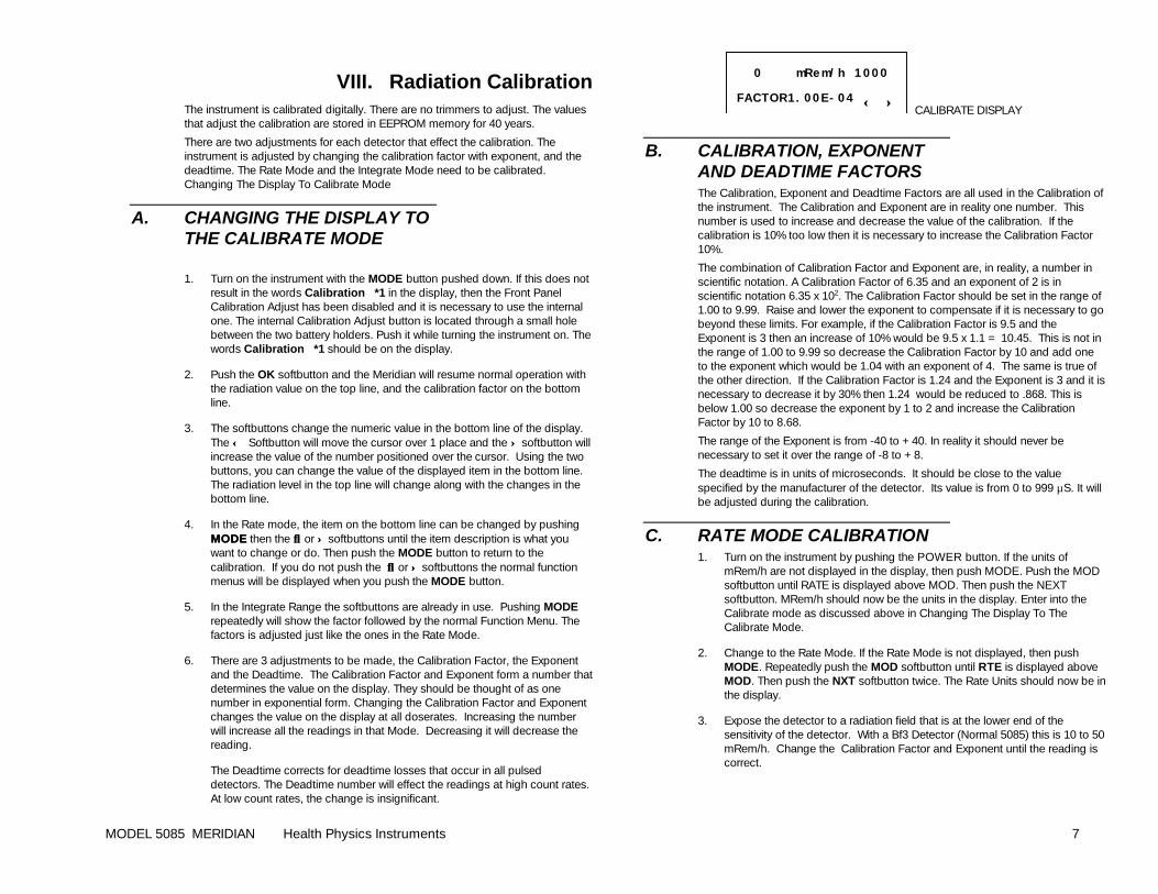
0 mRem/h 1000
FACTOR1. 00E- 04 ←← ↑↑ CALIBRATE DISPLAY
B. CALIBRATION, EXPONENT AND DEADTIME FACTORS The Calibration, Exponent and Deadtime Factors are all used in the Calibration of the instrument. The Calibration and Exponent are in reality one number. This number is used to increase and decrease the value of the calibration. If the calibration is 10% too low then it is necessary to increase the Calibration Factor 10%.
The combination of Calibration Factor and Exponent are, in reality, a number in scientific notation. A Calibration Factor of 6.35 and an exponent of 2 is in scientific notation 6.35 x 10². The Calibration Factor should be set in the range of 1.00 to 9.99. Raise and lower the exponent to compensate if it is necessary to go beyond these limits. For example, if the Calibration Factor is 9.5 and the Exponent is 3 then an increase of 10% would be 9.5 x 1.1 = 10.45. This is not in the range of 1.00 to 9.99 so decrease the Calibration Factor by 10 and add one to the exponent which would be 1.04 with an exponent of 4. The same is true of the other direction. If the Calibration Factor is 1.24 and the Exponent is 3 and it is necessary to decrease it by 30% then 1.24 would be reduced to .868. This is below 1.00 so decrease the exponent by 1 to 2 and increase the Calibration Factor by 10 to 8.68.
The range of the Exponent is from -40 to +40. In reality it should never be necessary to set it over the range of -8 to +8.
The deadtime is in units of microseconds. It should be close to the value specified by the manufacturer of the detector. Its value is from 0 to 999 µS. It will be adjusted during the calibration.
C. RATE MODE CALIBRATION 1. Turn on the instrument by pushing the POWER button. If the units of
mRem/h are not displayed in the display, then push MODE. Push the MOD softbutton until RATE is displayed above MOD. Then push the NEXT softbutton. MRem/h should now be the units in the display. Enter into the Calibrate mode as discussed above in Changing The Display To The Calibrate Mode.
2. Change to the Rate Mode. If the Rate Mode is not displayed, then push MODE. Repeatedly push the MOD softbutton until RTE is displayed above MOD. Then push the NXT softbutton twice. The Rate Units should now be in the display.
3. Expose the detector to a radiation field that is at the lower end of the sensitivity of the detector. With a Bf3 Detector (Normal 5085) this is 10 to 50 mRem/h. Change the Calibration Factor and Exponent until the reading is correct.
MODEL 5085 MERIDIAN Health Physics Instruments 8
4. Expose the detector to a field that is at the upper end of the sensitivity of the detector. With a Bf3 Detector (Normal 5085) this is 5085 to 10,000 mRem/h. Adjust the Deadtime until the reading is correct.
5. Repeat steps 3 and 4 until both settings are correct.
6. Expose each range/decade at 20% and 80% of full scale. Note the readings on the calibration report.
7. Turn the instrument off by pushing the POWER button when finished.
D. INTEGRATE MODE CALIBRATION 1. Enter into the Calibrate mode as discussed above in Changing The Display
To Calibrate Mode.
2. Change to the Integrate Mode. If the integrate Mode is not displayed, then push MODE. Repeatedly push the MODE softbutton until INT is displayed above MODE. Then push the NEXT softbutton twice. The Integrate range should now be in the display. Read section E below to determine if you want to use the Rate Range Calibration Factor to set the Integrate range Calibration Factor.
3. Expose the detector to a known dose in a radiation field that is at the lower end of the sensitivity of the detector.
4. Change the Calibration Factor and Exponent. Repeat step 3 until the reading is correct.
5. Expose two lower ranges at 80% of full scale. Note the readings on the calibration report. (The deadtime correction is already set in the Rate Mode.)
6. Turn the instrument off by pushing the POWER button when finished.
E. CAL FACTOR FOR INTEGRATE RANGE AND RATE RANGE The rate range calibration factor can be used to set the integrate range. If you are satisfied with the rate range calibration you may be able to use the rate range calibration factor as the basis for calculating the integrate range calibration factor. You may also choose to calibrate them independently.
If the integrate range is in the same prefix-units as the rate range then the rate range Calibration Factor can be used in calculating the integrate range Calibration Factor. If the rate range is in mR/h and the integrate range in mR then they are considered to have the same units.
Divide the rate range Calibration Factor with Exponent by 60 if the internal timebase is in CPM (Conventional Units) and by 3600 if the internal timebase is in CPS (SI units). Use this new calibration Factor and Exponent for the integrate range. If you use this Calibration Factor, then the rate range and integrate range will have the same calibration.
F. DETECTOR PLATEAU The High voltage is usually set by either using the recommended voltage from the manufacturer or by plotting the plateau.. All new instruments have been adjusted for operation on the plateau. The voltage is supplied on the calibration sheet. To plot the plateau:
1. Turn on the instrument with the MODEMODE button pushed down. If this does not result in the words Calibration *1Calibration *1 in the display, then the Front Panel Calibration Adjust has been disabled and it is necessary to use the internal one. The internal Calibration Adjust button is located through a small hole between the two battery holders. Push it while turning the instrument on. The words Calibration *1Calibration *1 should be on the display.
2. Push the ↑↑ softbutton until Det Setup *2Det Setup *2 is in the display. Then push the OK OK softbutton and the Meridian will resume normal operation with the radiation value on the top line, and the calibration factor on the bottom line.
3. Push the MODE MODE button and then use the ↓↓ or ↑↑ softbuttons until the words High Voltage shows in the display. Then push the OK OK softbutton. The instrument will resume normal operation with the High Voltage on the bottom line.
4. Expose the detector in a fixed geometry to a medium intensity radiation source.
5. If the instrument is reading a value other than zero, slowly lower the high voltage using the ↓↓ or ↑↑ softbuttons until the instrument reads zero. If the instrument is reading zero, raise the high voltage until it reads a low value.
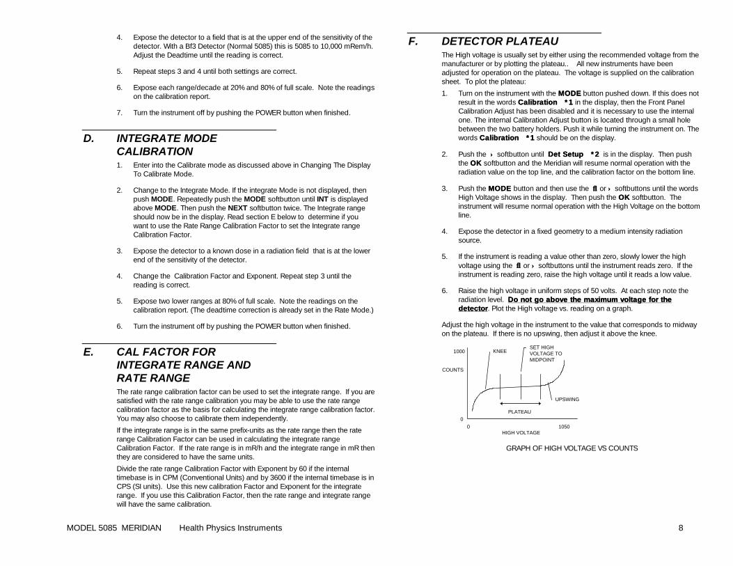
6. Raise the high voltage in uniform steps of 50 volts. At each step note the radiation level. Do not go above the maximuDo not go above the maximum voltage for the m voltage for the detectordetector. Plot the High voltage vs. reading on a graph.
Adjust the high voltage in the instrument to the value that corresponds to midway on the plateau. If there is no upswing, then adjust it above the knee.
KNEE
UPSWING
PLATEAU
0 1050 HIGH VOLTAGE
1000
COUNTS
0
SET HIGHVOLTAGE TOMIDPOINT
GRAPH OF HIGH VOLTAGE VS COUNTS
MODEL 5085 MERIDIAN Health Physics Instruments 9
IX. PROGRAMMING AND MAINTENANCE The Programming and Maintenance section of the manual contains items that are outside the scope of normal operation and calibration. You will be interested in this section if you want to customize the Meridian, use a different detector, or troubleshoot the electronics.
A. MAINTENANCE
1. Maintenance Mode This mode is useful for checking the operation of the instrument when it is needed for repair. Each menu item is used for checking, or changing some electrical part of the instrument.
If you do decide to change the settings with this menu, remember to disconnect the detector in case the high voltage changes. This mode does not change any stored value. The maintenance mode is reached through the following:
1. Turn on the instrument with the MODE button pushed down. If this does not result in the words Calibration *1 in the display then the Front Panel Calibration Adjust has been disabled and it is necessary to use the internal one. The internal Calibration Adjust button is located through a small hole between the two battery holders in the battery compartment. Push on this button while turning the instrument on. The words Calibration *1 should be on the display.
2. Advance the menus using the ↑↑ or ↓↓ softbutton until the display shows Maintenance *8. Then push OK. You are now in the Maintenance Mode.
a)a) Maintenance Mode Display DescriptionMaintenance Mode Display Description The Maintenance Mode display shows the selected item in the top left, the factor (in hex) associated with the item in the middle, and the counts from the detector for .1 second on the right. Pushing the NEXT softbutton on the bottom line will change between the items. The * softbutton will go back to the Setup Menus. The ↑↑ or ↓↓ softbuttons change the factor.
HV Changes the high voltage by varying the output voltage of pin 18 of U12 (HVDAC). This is the reference voltage of the HV section.
DISCR Changes the Discriminator by varying the output of pin 5 on U12 (DISCR). This is the reference voltage of U15.
SAT Measures the saturation voltage on the HV transformer.
LTE Turns the light on and off.
BUZ Turns the buzzer on and off. Needs an external input to cause the beeper to beep.
DIV Changes the divider to the buzzer.
BAT Shows the battery voltage.
MONITOR Switches to the monitor program to test and examine memory. Needs RS232 connection to work. To recover from this test, push the power button down for 10 seconds to reset the instrument or on the RS232 connection type G0.
2. High Voltage Calibration The high voltage displays on the Meridian are actually measured rather than just calculated. This measurement system may need calibration. Connect a high voltage high impedance meter with >10,000 megohm input resistance to the detector connector on the front panel. The meter should be capable of measuring 2200 Volts DC.
1. Turn the instrument on in the Setup Menu and change it to the HV Calibrate *6 Menu. Press ok to change into the HV calibrate display.
2. Measure the high voltage with the external voltmeter.
3. Using the ↑ and ↓ softbuttons change the Cal: number until the HV: is as close as possible to the measured high voltage.
4. Push the ok softbutton to save the value. Push the POWER button if you do not want to change the calibration.
3. Failure in Display If the display says FAILURE, then the EEPROM has failed. This may mean that is it corrupted or that it is not working. In any case you should try to reprogram it which may preserve many of the settings.
1. Turn the instrument on after the display shows Failure #1, push the internal CAL button on the back of the main circuit board. It is accessable through a small hole between the battery holders. The display will change to the Setup Menu.
2. Advance the menus using the ↑↑ or ↓↓ softbutton until the displays shows the Custom Set *3 . Then push OK. Push the POWER button to change the cursor to the Data. Use the ←← and ↑↑ softbuttons to change the Data to 26. Then push the POWER button then the MODE button twice.
3. If the display shows a normal turn on, then the EEPROM was only corrupted a little, and it would be wise to check the calibration and operation of the instrument. If it shows a Failure #1, then the EEPROM is defective and should be replaced.
4. Installing a New EEPROM When installing a new EEPROM it is necessary to program it to the default values. It will show Failure #1 in the display until it is programmed.
1. Turn the instrument on after the display shows Failure #1, push the internal CAL button on the back of the main circuit board. It is accessable through a small hole between the battery holders. The display will change to the Setup Menu.
2. Advance the menus using the ↑↑ or ↓↓ softbutton until the display shows the Factory Set *9. Then push OK, answer the question on CPM (answer no if you want CPS or SI units), and then Yes to Are you sure?. It will take 30 seconds to program the entire EEPROM.
MODEL 5085 MERIDIAN Health Physics Instruments 10
3. After it is done programming, push the Mode button to resume normal operation.
4. Check the new EEPROM by turning the instrument on and off. If it turns on without the failure warning, then it has been programmed.
5. The instrument will now need to be completely recalibrated.
5. Factory Settings To program the instrument with the factory settings:
1. Turn on the instrument with the MODE button pushed down. If this does not result in the words Calibration *1 in the display then the Front Panel Calibration Adjust has been disabled and it is necessary to use the internal one. The internal Calibration Adjust button is located through a small hole between the two battery holders in the battery compartment. Push on this button while turning the instrument on. The words Calibration *1 should be on the display.
2. Advance the menus using the ↑↑ or ↓↓ softbutton until the display shows the Factory Set *9. Then push OK, answer the question on CPM (answer no if you want CPS or SI units), and then Yes to Are you sure?. It will take 30 seconds to program the entire EEPROM.
3. After it is done programming, push the Mode button to resume normal operation.
4. The instrument will now need to be completely recalibrated. The calibration sheet that was shipped with the instrument contains the calibration factors that can be used to reprogram the instrument.
B. SETUP MENUS The Setup Menus are special menus that are different than the normal operation of the instrument. These menus allow adjustment and setting of all the variables in the instrument. These include for example, the button definitions, the calibration values, the operating displays, the detector settings and the defaults.
1. Accessing The Setup Menus These menus are not available in any of the normal operating modes. There are 2 ways to enter into the Setup Menus. The first method, which is always available is to push a switch on the inside of the case. The second method is through the front panel, but it may be user disabled. The two methods are:
a)a) METHOD 1 INTERNAL BUTTONMETHOD 1 INTERNAL BUTTON 1. If the instrument is on, turn it off.
2. Remove the battery cover on the back of the display box.
3. Between the two battery holders is a small hole. Push the pushbutton behind this hole while you are turning on the instrument. Use a paperclip or any other small item that will fit through the hole. The display should show the first Setup Menu.
b)b) METHOD 2 EXTERNAL BUTTONMETHOD 2 EXTERNAL BUTTON 1. If the instrument is on, turn it off.
2. Push the MODE button and hold it down, then push the POWER button. Continue to hold down the MODE button until the Setup Menu appears. If the regular turn on menu appears instead, then the front panel has been disabled and it is necessary to use the internal button in Method 1
2. Scrolling Through The Setup Menus The Setup Menu is the main menu that directs you to several other menus or operations. The top line of the display shows the selection that is offered followed by a number. Each item is numbered and has a * before the number to identify it. The bottom line contains the ↑ softbutton and ↓ softbutton and the ok softbutton. Push the ↑softbutton to go to the next item on the list. Push the ↓ softbutton to go to the pervious item on the list. When you have the selection that you want, push the ok softbutton. The screen will then change to the new item.
3. * Setup Menu Selection
The following is a list of menu selections in Setup. Each selection has a * followed by a selection number to make it easier to find. If a Softbutton is labeled * this means that pushing it will get back to this menu.
The * menu selections and their definitions are listed below.
a)a) Calibrate *1Calibrate *1 This is the menu to change the calibration of the instrument. Please see the Calibration and Detector Setup Menus for a full understanding of how to use this menu. Also see the section on Calibration to understand the settings. It is used to change the following: Calibration Factor, Exponent, and Deadtime.
b)b) Detector Setup *2Detector Setup *2 This is the menu to change both the calibration of the instrument and the setup of the detector. Please see the section on Detector Setup Menu for a complete description of this menu. It is used to change the following: Calibration Factor, Exponent, Deadtime in/out, Deadtime, High Voltage, Saturation, Discriminator, Range High Limit, Range Low Limit, Units, Prefix, and Timebase
c)c) Custom Settings *3Custom Settings *3 This is the menu to change individual memory locations in the EEPROM that in turn program the instrument. All of the instrument variables are stored in the EEPROM. This menu allows complete access to all the possible changes and setups in the instrument. It allows you to change everything changeable about the instrument. Please see the section on Custom Settings for a complete description of this menu.
d)d) Front Panel *4Front Panel *4 The Calibration and Setup Menus can be reached through the front panel or internally. This menu changes the access from the front panel. It also turns on and off the Adjust MenuAdjust Menu for the Quick-keys. The choices are: Front panel Front panel on/offon/off, Adjust on/offAdjust on/off for all modes or for just the scaler. See the Operational section for more information on Adjust. If you want to be able to calibrate the instrument from the front panel push yes. If you want to be able to access the Adjust from all modes then push yes to the next question, and if you want to
MODEL 5085 MERIDIAN Health Physics Instruments 11
adjust only in the scaler mode push yes to the next question and no to the previous question.
e)e) Automatic Turn Off *5Automatic Turn Off *5 The instrument has the capability to automatically turn itself off if it is not in use. This menu turns that capability on and off. If you want the instrument to automatically turn off then push yes. This will automatically turn it off after the time that is programmed into the instrument. The default value is 108 minutes. See and power time in Custom Setting section for more information on setting the value..
f)f) High Voltage Calibrate *6High Voltage Calibrate *6 The high voltage is displayed in several menus. This is a measured high voltage. This menu adjusts the calibration of the high voltage measurement so the value will be displayed correctly. It does not change the actual voltage of the high voltage. See the section on Maintenance for more information.
g)g) High Voltage Setting *7High Voltage Setting *7 This menu will adjust the setting of the high voltage. It allows you to preset the value of the high voltage for a particular detector without having to go into any other Menu. The top line of the display shows, after the HV:, the actual measured value of the high voltage. The number after the Fac: is the high voltage factor which is a number that the instrument uses to set the high voltage. It is also the number that is put into the memory to represent that high voltage. Select which detector you want to change using the det softbutton. The choices are detector 1, 2 or 3. Use the ↓↓ or ↑↑ softbuttons to change the value of the factor which in turn raises and lowers the actual high voltage. Save the data by pushing the sav softbutton after which the menu will change back to the * or Setup Menu. To change another detector, just push the ok softbutton.
h)h) Maintenance *8Maintenance *8 This menu will allow adjustment of several parameters without changing their permanent values. The adjustments include high voltage, discriminator, saturation, light, beeper, divisor, and battery. In addition it will allow the use of a monitor program. See the section on Maintenance for more information.
i)i) Factory Setting *9Factory Setting *9 This setting is used at the factory to preset the instrument. The settings are the same as the Standard Instrument PresetStandard Instrument Preset combined with the Bf3 detector. In addition it sets up and programs all the other parameters such as contrast, user characters, and current mode to start the instrument operation off properly. See the section on Factory Settings in Maintenance.
This is also the menu to change the internal timebase from CPM to CPS. Internally the instrument calculates the basic rates from counts per minute or counts per second. This control changes that setting. If this setting is in CPS then any presets for Preset Instrument or Preset Detector will be in SI units. If you want CPM, answer yes to the question CPM Timebase?. For more information see the section on Programming: Internal Timebase.
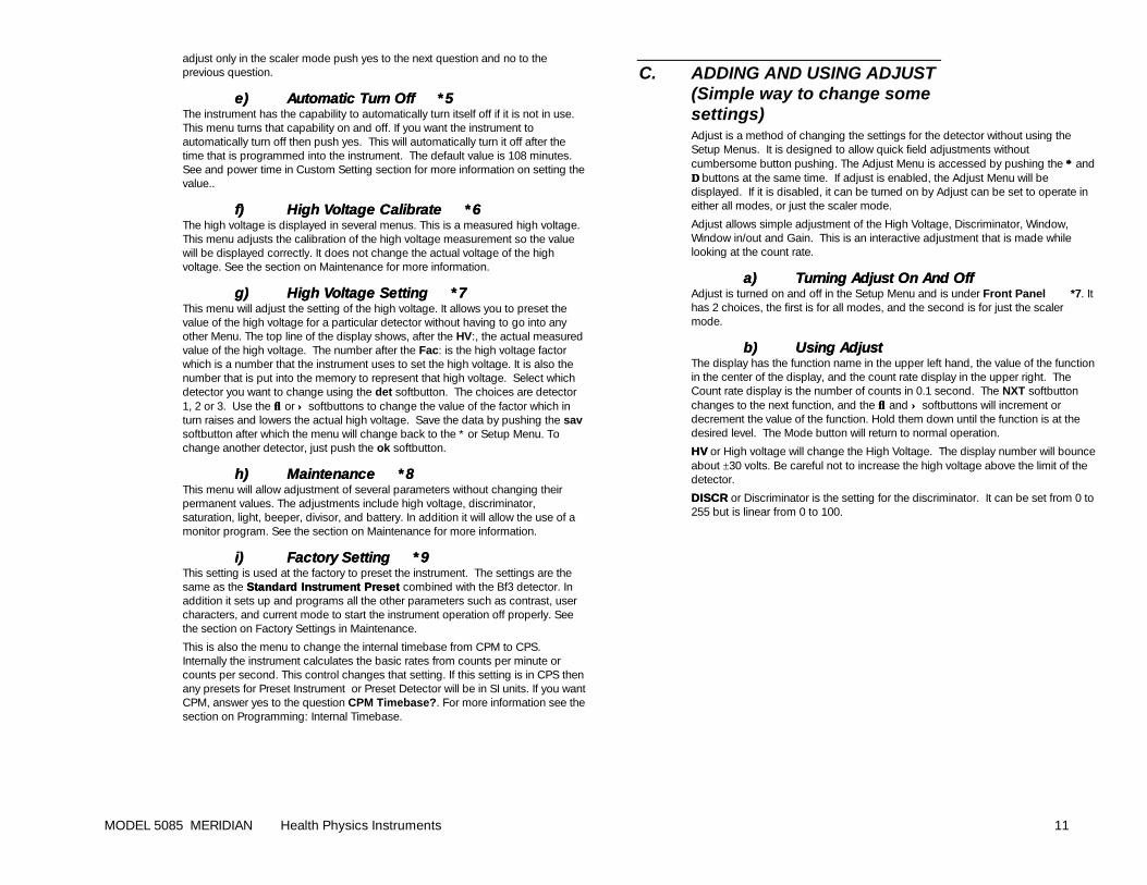
C. ADDING AND USING ADJUST (Simple way to change some settings) Adjust is a method of changing the settings for the detector without using the Setup Menus. It is designed to allow quick field adjustments without cumbersome button pushing. The Adjust Menu is accessed by pushing the ∗∗ and ∆∆ buttons at the same time. If adjust is enabled, the Adjust Menu will be displayed. If it is disabled, it can be turned on by Adjust can be set to operate in either all modes, or just the scaler mode.
Adjust allows simple adjustment of the High Voltage, Discriminator, Window, Window in/out and Gain. This is an interactive adjustment that is made while looking at the count rate.
a)a) Turning Adjust On And OffTurning Adjust On And Off Adjust is turned on and off in the Setup Menu and is under Front Panel *7. It has 2 choices, the first is for all modes, and the second is for just the scaler mode.
b)b) Using AdjustUsing Adjust The display has the function name in the upper left hand, the value of the function in the center of the display, and the count rate display in the upper right. The Count rate display is the number of counts in 0.1 second. The NXT softbutton changes to the next function, and the ↓↓ and ↑↑ softbuttons will increment or decrement the value of the function. Hold them down until the function is at the desired level. The Mode button will return to normal operation.
HVHV or High voltage will change the High Voltage. The display number will bounce about ±30 volts. Be careful not to increase the high voltage above the limit of the detector.
DISCRDISCR or Discriminator is the setting for the discriminator. It can be set from 0 to 255 but is linear from 0 to 100.
MODEL 5085 MERIDIAN Health Physics Instruments 12
D. CUSTOMIZING THE MERIDIAN The Meridian may be customized by changing the variables. The operation of the instrument is very programmable and is based on the Cypher Survey Meter which is a very programmable instrument. The section on the Custom Menu describes each of the variables. The Description of Custom Setting Menu shows all the possible settings for the Meridian. We offer the following tips and suggestions on how to change the instrument to meet your particular needs.
1. Buttons Probably the most useful changes to the instrument revolve around the buttons. This includes both the Quick-keys and the Function Menus. They both can be modified to meet your needs.
The Quick-keys are the buttons that are on the right hand side of the panel and are active during CPM/S, Rate and User Modes. These are also referred to as the ∗∗ and ∆∆ Quick-keys. In the Meridian the quickeys are predefined as the light and speaker buttons and they are factory set to Beeper and Light, which are probably the most generic uses of the controls on a survey meter. There are 7 other choices that are available. If you do not need the light or beeper, then you may consider using either button for either the Range Hold, Hold or contrast. The other options are listed under the ∗ or ∆ Buttons in Custom Settings.
There is 1 Function Menus with the factory settings. If you need more capability, such as range hold, you could change up to 3 Function Menus.
The location of the functions within the Function Menu can also be changed. Each of the three locations above the three right hand buttons is available for any of the functions. If you are left handed and use the MODE button frequently, consider moving it to the left hand side of the instrument. (Changing location 18 from 5 to 10 and location 20 from 10 to 5 in the Custom Menu will swap the MOD and RHH .) We usually put the most used functions on the first menu.
2. Display The display is the other part of the instrument that can be customized to fit your needs. Particularly important is the full scale range of the bargraph. We have it set at 10 for the factory settings, however many survey meters have 50, 500, and 5085 CPM full scale primarily to put background counts from pancake GM detectors farther up the scale. If you wanted to emulate one of these meters, change the Bargraph Type to 2 in Custom Setup. There also is a 2.5, 25, 250 and 2500 full scale available.
If you are using the instrument in areas where the bargraph may confuse some people, you can turn it off by setting the bargraph to off in Display Configuration in the Custom Setup Menu. Just read the current value, look at the table and find out the current settings. Then look for the same settings but with the bargraph off and change the data to the new value.
We also offer the choice of normal or inverted display with the bargraph on top. This may be useful for some applications where you need 2 different bargraph scales, perhaps one a log scale for mR/h and one a linear scale for CPM.
The Range Up and Down Time allow the instrument to dwell on a range without going up or down a range quickly. The Range Up Time would be useful for
contamination surveying near background where there are hot spots. It would keep the range from going to the next higher range quickly. It may be set to 2 or 3 seconds. Likewise you may be using the detector in high radiation levels and not want it to range down during a momentary dip in radiation. In this case increasing the Range Down Time would be useful. Set both of these in the Custom Setting Menu.
3. Modes The modes can be turned on or off. This allows the instrument to function in whatever capacity you want. If you do not need a scaler or an integrate range, turn them off using the Mode Lockout in the Custom Settings. There is also a User Mode that can be programmed in any rate units you want. Use the Mode Lockout in the Custom Settings Mode to turn on this mode. Then program it in the Setting Up a New Detector section for the units, prefix, etc., just the same as the rate range.
The CPM/S range can also be changed into any units. It does not have to be used for CPM/S
4. Internal Time Base The internal timebase of the Meridian can be in Counts per Minute or in Counts per Second. In general, CPM is used with conventional units, and CPS is used with SI units. See the section on Programming: Internal Timebase for more information.
5. Detector There are a maximum of 3 detectors that can be used with the Meridian if each needs its own set of settings. Of course, any number can be used with the same settings. For example, many GM detectors use the same high voltage and all should be used on the CPM/S range. However all would not read correctly with the Rate Range. To add detectors you will need to either make a DET Function Menu or Soft Button. In addition you will need to set the Detector Max. See section above on Buttons.
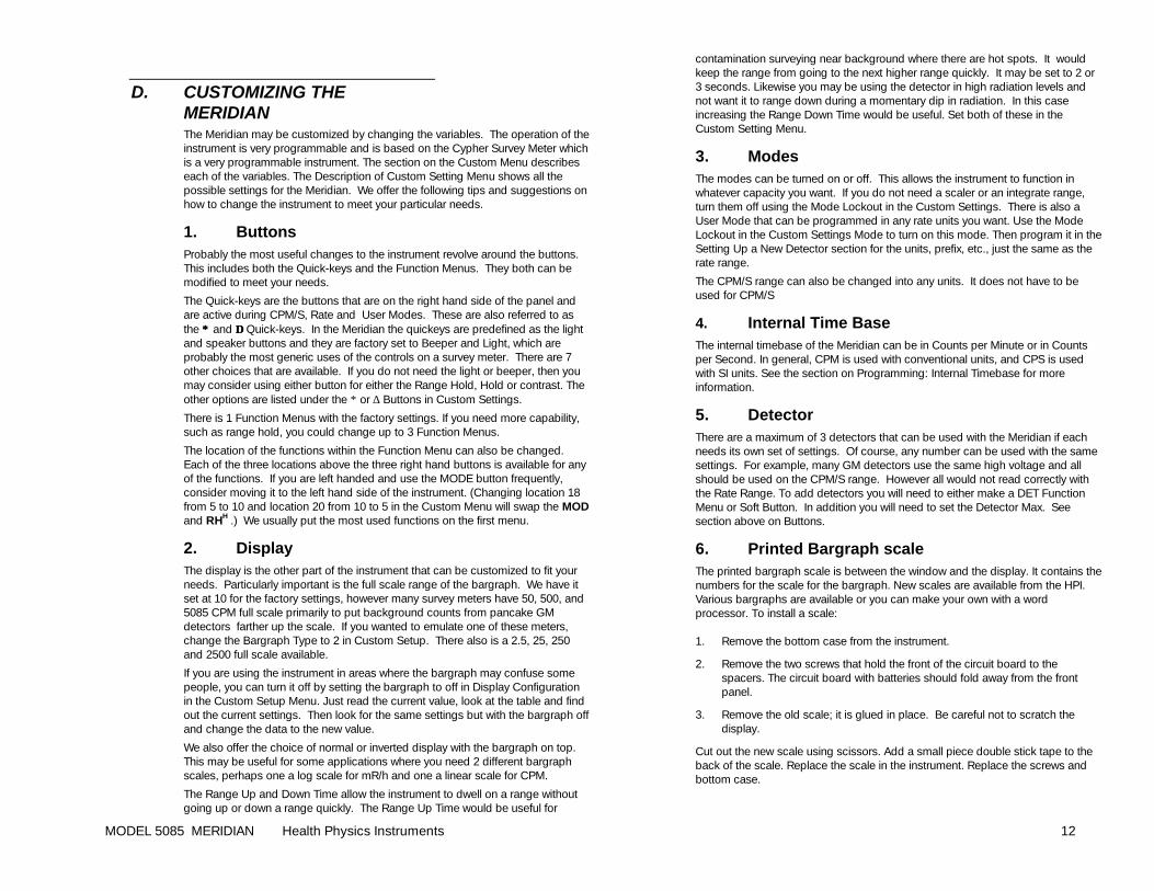
6. Printed Bargraph scale The printed bargraph scale is between the window and the display. It contains the numbers for the scale for the bargraph. New scales are available from the HPI. Various bargraphs are available or you can make your own with a word processor. To install a scale: 1. Remove the bottom case from the instrument.
2. Remove the two screws that hold the front of the circuit board to the spacers. The circuit board with batteries should fold away from the front panel.
3. Remove the old scale; it is glued in place. Be careful not to scratch the display.
Cut out the new scale using scissors. Add a small piece double stick tape to the back of the scale. Replace the scale in the instrument. Replace the screws and bottom case.
MODEL 5085 MERIDIAN Health Physics Instruments 13
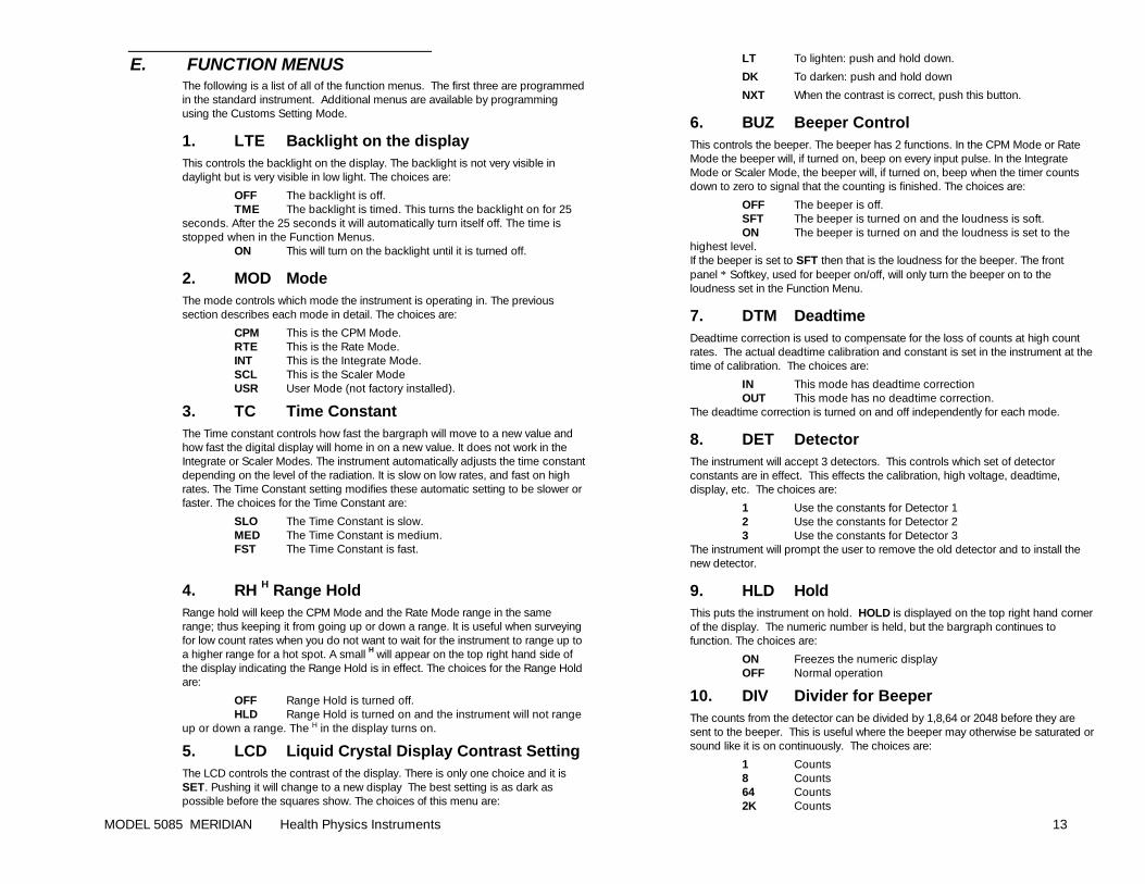
E. FUNCTION MENUS The following is a list of all of the function menus. The first three are programmed in the standard instrument. Additional menus are available by programming using the Customs Setting Mode.
1. LTE Backlight on the display This controls the backlight on the display. The backlight is not very visible in daylight but is very visible in low light. The choices are:
OFF The backlight is off. TME The backlight is timed. This turns the backlight on for 25 seconds. After the 25 seconds it will automatically turn itself off. The time is stopped when in the Function Menus. ON This will turn on the backlight until it is turned off.
2. MOD Mode The mode controls which mode the instrument is operating in. The previous section describes each mode in detail. The choices are:
CPM This is the CPM Mode. RTE This is the Rate Mode. INT This is the Integrate Mode. SCL This is the Scaler Mode USR User Mode (not factory installed).
3. TC Time Constant The Time constant controls how fast the bargraph will move to a new value and how fast the digital display will home in on a new value. It does not work in the Integrate or Scaler Modes. The instrument automatically adjusts the time constant depending on the level of the radiation. It is slow on low rates, and fast on high rates. The Time Constant setting modifies these automatic setting to be slower or faster. The choices for the Time Constant are:
SLO The Time Constant is slow. MED The Time Constant is medium. FST The Time Constant is fast.
4. RH H Range Hold Range hold will keep the CPM Mode and the Rate Mode range in the same range; thus keeping it from going up or down a range. It is useful when surveying for low count rates when you do not want to wait for the instrument to range up to a higher range for a hot spot. A small H will appear on the top right hand side of the display indicating the Range Hold is in effect. The choices for the Range Hold are:
OFF Range Hold is turned off. HLD Range Hold is turned on and the instrument will not range up or down a range. The H in the display turns on.
5. LCD Liquid Crystal Display Contrast Setting The LCD controls the contrast of the display. There is only one choice and it is SET. Pushing it will change to a new display The best setting is as dark as possible before the squares show. The choices of this menu are:
LT To lighten: push and hold down.
DK To darken: push and hold down
NXT When the contrast is correct, push this button.
6. BUZ Beeper Control This controls the beeper. The beeper has 2 functions. In the CPM Mode or Rate Mode the beeper will, if turned on, beep on every input pulse. In the Integrate Mode or Scaler Mode, the beeper will, if turned on, beep when the timer counts down to zero to signal that the counting is finished. The choices are:
OFF The beeper is off. SFT The beeper is turned on and the loudness is soft. ON The beeper is turned on and the loudness is set to the highest level. If the beeper is set to SFT then that is the loudness for the beeper. The front panel ∗ Softkey, used for beeper on/off, will only turn the beeper on to the loudness set in the Function Menu.
7. DTM Deadtime Deadtime correction is used to compensate for the loss of counts at high count rates. The actual deadtime calibration and constant is set in the instrument at the time of calibration. The choices are:
IN This mode has deadtime correction OUT This mode has no deadtime correction. The deadtime correction is turned on and off independently for each mode.
8. DET Detector The instrument will accept 3 detectors. This controls which set of detector constants are in effect. This effects the calibration, high voltage, deadtime, display, etc. The choices are:
1 Use the constants for Detector 1 2 Use the constants for Detector 2 3 Use the constants for Detector 3 The instrument will prompt the user to remove the old detector and to install the new detector.
9. HLD Hold This puts the instrument on hold. HOLD is displayed on the top right hand corner of the display. The numeric number is held, but the bargraph continues to function. The choices are:
ON Freezes the numeric display OFF Normal operation
10. DIV Divider for Beeper The counts from the detector can be divided by 1,8,64 or 2048 before they are sent to the beeper. This is useful where the beeper may otherwise be saturated or sound like it is on continuously. The choices are:
1 Counts 8 Counts 64 Counts 2K Counts
MODEL 5085 MERIDIAN Health Physics Instruments 14
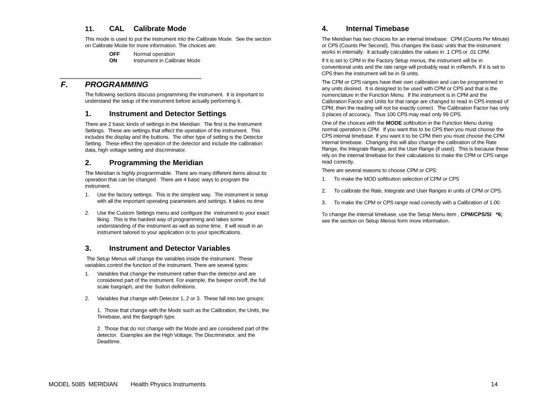
11. CAL Calibrate Mode This mode is used to put the instrument into the Calibrate Mode. See the section on Calibrate Mode for more information. The choices are:
OFF Normal operation ON Instrument in Calibrate Mode
F. PROGRAMMING The following sections discuss programming the instrument. It is important to understand the setup of the instrument before actually performing it.
1. Instrument and Detector Settings There are 2 basic kinds of settings in the Meridian. The first is the Instrument Settings. These are settings that effect the operation of the instrument. This includes the display and the buttons. The other type of setting is the Detector Setting. These effect the operation of the detector and include the calibration data, high voltage setting and discriminator.
2. Programming the Meridian The Meridian is highly programmable. There are many different items about its operation that can be changed. There are 4 basic ways to program the instrument.
1. Use the factory settings. This is the simplest way. The instrument is setup with all the important operating parameters and settings. It takes no time
2. Use the Custom Settings menu and configure the instrument to your exact liking. This is the hardest way of programming and takes some understanding of the instrument as well as some time. It will result in an instrument tailored to your application or to your specifications.
3. Instrument and Detector Variables The Setup Menus will change the variables inside the instrument. These variables control the function of the instrument. There are several types:
1. Variables that change the instrument rather than the detector and are considered part of the instrument. For example, the beeper on/off, the full scale bargraph, and the button definitions.
2. Variables that change with Detector 1, 2 or 3. These fall into two groups:
1. Those that change with the Mode such as the Calibration, the Units, the Timebase, and the Bargraph type.
2. Those that do not change with the Mode and are considered part of the detector. Examples are the High Voltage, The Discriminator, and the Deadtime.
4. Internal Timebase The Meridian has two choices for an internal timebase: CPM (Counts Per Minute) or CPS (Counts Per Second). This changes the basic units that the instrument works in internally. It actually calculates the values in .1 CPS or .01 CPM.
If it is set to CPM in the Factory Setup menus, the instrument will be in conventional units and the rate range will probably read in mRem/h. If it is set to CPS then the instrument will be in SI units.
The CPM or CPS ranges have their own calibration and can be programmed in any units desired. It is designed to be used with CPM or CPS and that is the nomenclature in the Function Menu. If the instrument is in CPM and the Calibration Factor and Units for that range are changed to read in CPS instead of CPM, then the reading will not be exactly correct. The Calibration Factor has only 3 places of accuracy, Thus 100 CPS may read only 99 CPS.
One of the choices with the MODE softbutton in the Function Menu during normal operation is CPM. If you want this to be CPS then you must choose the CPS internal timebase. If you want it to be CPM then you must choose the CPM internal timebase. Changing this will also change the calibration of the Rate Range, the Integrate Range, and the User Range (if used). This is because these rely on the internal timebase for their calculations to make the CPM or CPS range read correctly.
There are several reasons to choose CPM or CPS:
1. To make the MOD softbutton selection of CPM or CPS
2. To calibrate the Rate, Integrate and User Ranges in units of CPM or CPS.
3. To make the CPM or CPS range read correctly with a Calibration of 1.00.
To change the internal timebase, use the Setup Menu item , CPM/CPS/SI *6; see the section on Setup Menus form more information.
MODEL 5085 MERIDIAN Health Physics Instruments 15
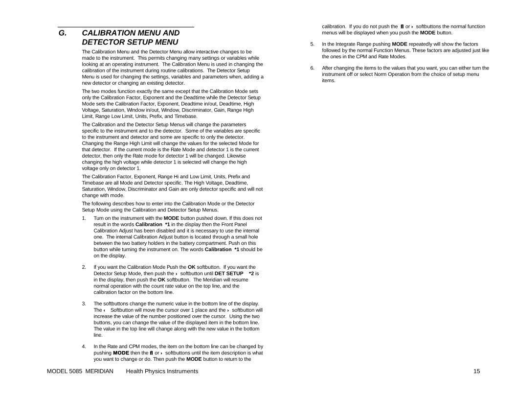
G. CALIBRATION MENU AND DETECTOR SETUP MENU The Calibration Menu and the Detector Menu allow interactive changes to be made to the instrument. This permits changing many settings or variables while looking at an operating instrument. The Calibration Menu is used in changing the calibration of the instrument during routine calibrations. The Detector Setup Menu is used for changing the settings, variables and parameters when, adding a new detector or changing an existing detector.
The two modes function exactly the same except that the Calibration Mode sets only the Calibration Factor, Exponent and the Deadtime while the Detector Setup Mode sets the Calibration Factor, Exponent, Deadtime in/out, Deadtime, High Voltage, Saturation, Window in/out, Window, Discriminator, Gain, Range High Limit, Range Low Limit, Units, Prefix, and Timebase.
The Calibration and the Detector Setup Menus will change the parameters specific to the instrument and to the detector. Some of the variables are specific to the instrument and detector and some are specific to only the detector. Changing the Range High Limit will change the values for the selected Mode for that detector. If the current mode is the Rate Mode and detector 1 is the current detector, then only the Rate mode for detector 1 will be changed. Likewise changing the high voltage while detector 1 is selected will change the high voltage only on detector 1.
The Calibration Factor, Exponent, Range Hi and Low Limit, Units, Prefix and Timebase are all Mode and Detector specific. The High Voltage, Deadtime, Saturation, Window, Discriminator and Gain are only detector specific and will not change with mode.
The following describes how to enter into the Calibration Mode or the Detector Setup Mode using the Calibration and Detector Setup Menus.
1. Turn on the instrument with the MODE button pushed down. If this does not result in the words Calibration *1 in the display then the Front Panel Calibration Adjust has been disabled and it is necessary to use the internal one. The internal Calibration Adjust button is located through a small hole between the two battery holders in the battery compartment. Push on this button while turning the instrument on. The words Calibration *1 should be on the display.
2. If you want the Calibration Mode Push the OK softbutton. If you want the Detector Setup Mode, then push the ↑↑ softbutton until DET SETUP *2 is in the display, then push the OK softbutton. The Meridian will resume normal operation with the count rate value on the top line, and the calibration factor on the bottom line.
3. The softbuttons change the numeric value in the bottom line of the display. The ←← Softbutton will move the cursor over 1 place and the ↑↑ softbutton will increase the value of the number positioned over the cursor. Using the two buttons, you can change the value of the displayed item in the bottom line. The value in the top line will change along with the new value in the bottom line.
4. In the Rate and CPM modes, the item on the bottom line can be changed by pushing MODEMODE then the ↓↓ or ↑↑ softbuttons until the item description is what you want to change or do. Then push the MODE button to return to the
calibration. If you do not push the ↓↓ or ↑↑ softbuttons the normal function menus will be displayed when you push the MODE button.
5. In the Integrate Range pushing MODE repeatedly will show the factors followed by the normal Function Menus. These factors are adjusted just like the ones in the CPM and Rate Modes.
6. After changing the items to the values that you want, you can either turn the instrument off or select Norm Operation from the choice of setup menu items.
MODEL 5085 MERIDIAN Health Physics Instruments 16
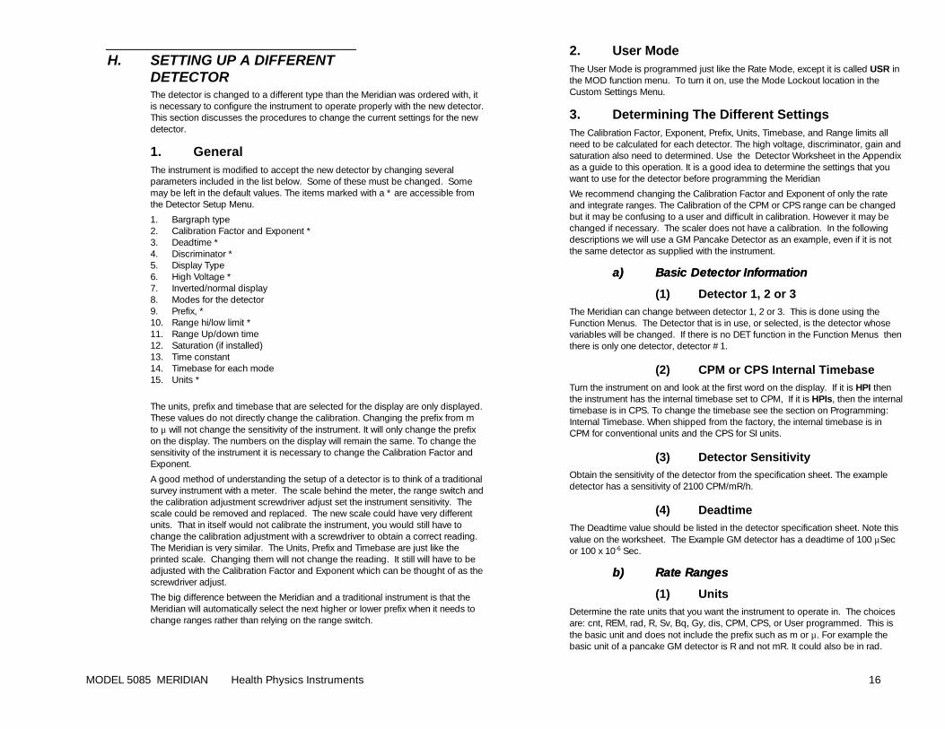
H. SETTING UP A DIFFERENT DETECTOR The detector is changed to a different type than the Meridian was ordered with, it is necessary to configure the instrument to operate properly with the new detector. This section discusses the procedures to change the current settings for the new detector.
1. General The instrument is modified to accept the new detector by changing several parameters included in the list below. Some of these must be changed. Some may be left in the default values. The items marked with a * are accessible from the Detector Setup Menu.
1. Bargraph type 2. Calibration Factor and Exponent * 3. Deadtime * 4. Discriminator * 5. Display Type 6. High Voltage * 7. Inverted/normal display 8. Modes for the detector 9. Prefix, * 10. Range hi/low limit * 11. Range Up/down time 12. Saturation (if installed) 13. Time constant 14. Timebase for each mode 15. Units *
The units, prefix and timebase that are selected for the display are only displayed. These values do not directly change the calibration. Changing the prefix from m to µ will not change the sensitivity of the instrument. It will only change the prefix on the display. The numbers on the display will remain the same. To change the sensitivity of the instrument it is necessary to change the Calibration Factor and Exponent.
A good method of understanding the setup of a detector is to think of a traditional survey instrument with a meter. The scale behind the meter, the range switch and the calibration adjustment screwdriver adjust set the instrument sensitivity. The scale could be removed and replaced. The new scale could have very different units. That in itself would not calibrate the instrument, you would still have to change the calibration adjustment with a screwdriver to obtain a correct reading. The Meridian is very similar. The Units, Prefix and Timebase are just like the printed scale. Changing them will not change the reading. It still will have to be adjusted with the Calibration Factor and Exponent which can be thought of as the screwdriver adjust.
The big difference between the Meridian and a traditional instrument is that the Meridian will automatically select the next higher or lower prefix when it needs to change ranges rather than relying on the range switch.
2. User Mode The User Mode is programmed just like the Rate Mode, except it is called USR in the MOD function menu. To turn it on, use the Mode Lockout location in the Custom Settings Menu.
3. Determining The Different Settings The Calibration Factor, Exponent, Prefix, Units, Timebase, and Range limits all need to be calculated for each detector. The high voltage, discriminator, gain and saturation also need to determined. Use the Detector Worksheet in the Appendix as a guide to this operation. It is a good idea to determine the settings that you want to use for the detector before programming the Meridian
We recommend changing the Calibration Factor and Exponent of only the rate and integrate ranges. The Calibration of the CPM or CPS range can be changed but it may be confusing to a user and difficult in calibration. However it may be changed if necessary. The scaler does not have a calibration. In the following descriptions we will use a GM Pancake Detector as an example, even if it is not the same detector as supplied with the instrument.
a)a) Basic Detector InformationBasic Detector Information
(1) Detector 1, 2 or 3 The Meridian can change between detector 1, 2 or 3. This is done using the Function Menus. The Detector that is in use, or selected, is the detector whose variables will be changed. If there is no DET function in the Function Menus then there is only one detector, detector #1.
(2) CPM or CPS Internal Timebase Turn the instrument on and look at the first word on the display. If it is HPI then the instrument has the internal timebase set to CPM, If it is HPIs, then the internal timebase is in CPS. To change the timebase see the section on Programming: Internal Timebase. When shipped from the factory, the internal timebase is in CPM for conventional units and the CPS for SI units.
(3) Detector Sensitivity Obtain the sensitivity of the detector from the specification sheet. The example detector has a sensitivity of 2100 CPM/mR/h.
(4) Deadtime The Deadtime value should be listed in the detector specification sheet. Note this value on the worksheet. The Example GM detector has a deadtime of 100 µSec or 100 x 10-6 Sec.
b)b) Rate RangesRate Ranges
(1) Units Determine the rate units that you want the instrument to operate in. The choices are: cnt, REM, rad, R, Sv, Bq, Gy, dis, CPM, CPS, or User programmed. This is the basic unit and does not include the prefix such as m or µ. For example the basic unit of a pancake GM detector is R and not mR. It could also be in rad.
MODEL 5085 MERIDIAN Health Physics Instruments 17
Note the units in the space provided on the worksheet and also the corresponding number from the table on the worksheet.
(2) Prefix Determine the prefix for the main rate range of the instrument. If you want the instrument to work in µR/h then the basic units would be µ. This assumes that the detector works in that range. Don’t try to set the instrument to read in R/h when the basic units should be µR/h. For example the Pancake GM detector would want to read in mR/h. µR/h would result in the display being too large a number, and R would result in it being too small a number. Note the prefix and the corresponding number from the table in the worksheet.
(3) Timebase Select the timebase of /h,/m or /s. If you need another timebase, use the User setting under Units. Note the timebase and the corresponding number from the table in the worksheet.
(4) Calibration Factor and Exponent
If the internal time base is set to CPM then determine the CPM/prefix-units/timebase. For example for a pancake detector that should read in mR/h, determine the CPM/mR/h. This is 2100 CPM/mR/h. If this number is below .1 CPM/prefix-units/timebase or above 10,000 CPM/prefix-units/timebase, then think about changing the prefix up or down to compensate. A detector with 50,000 CPM/mR/h has the prefix set too high. It should be reduced to 50 CPM/µR/h in which case the prefix would be µ.
If the internal time base is set to CPS then determine the CPS/prefix-base/timebase units. For example for a pancake detector that should read in µGy/h, determine the CPS/µGy/h which is 3.5 CPS/µGy/h. If this number is below 0.01 CPS/prefix-units/timebase or above 1000 CPM/prefix-units/timebase, then think about changing the prefix up or down to compensate.
Take the reciprocal of the number and convert to scientific notation. For example 1/2100= 0.000476 = 4.76 x 10⁻⁴. The formula is:
1/(sensitivity in prefix 1/(sensitivity in prefix--units/timebase)units/timebase)
This is the calibration number. In the example, 4.76 is the Calibration Factor, and -4 is the Exponent. The range of the Exponent is from -10 to +10. If it is beyond this range, change the prefix and recalculate the Calibration Factor and Exponent. Note these values in the worksheet.
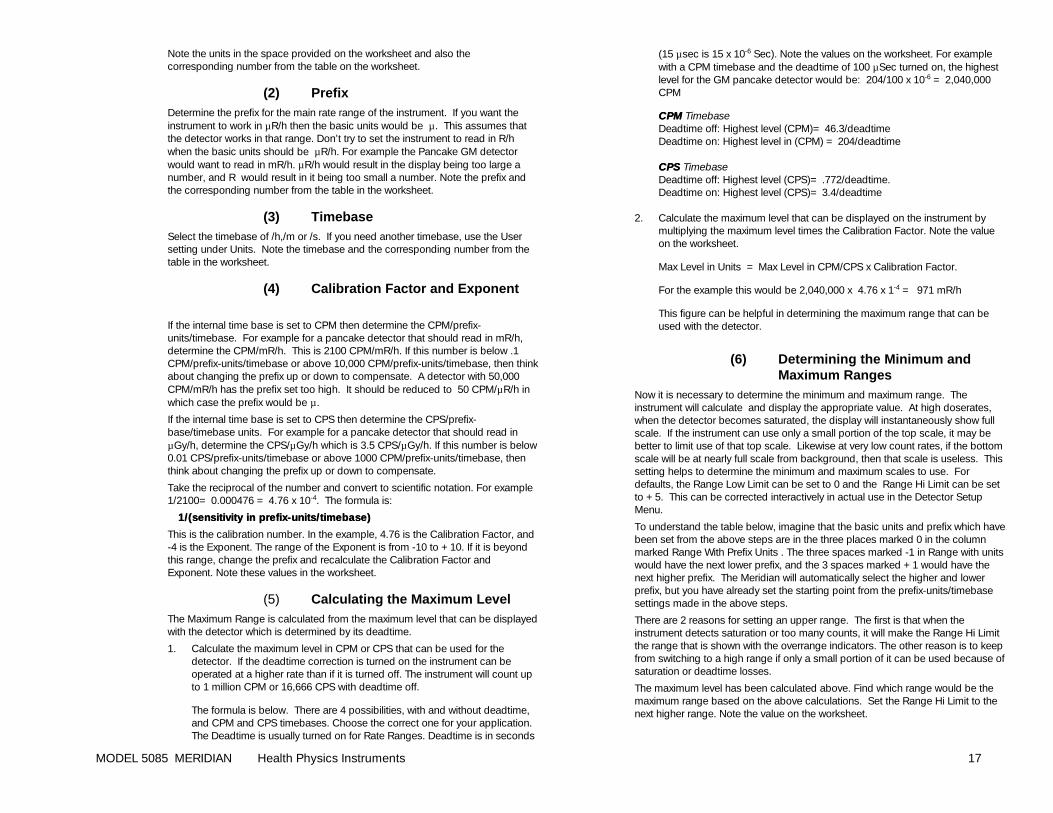
(5) Calculating the Maximum Level The Maximum Range is calculated from the maximum level that can be displayed with the detector which is determined by its deadtime.
1. Calculate the maximum level in CPM or CPS that can be used for the detector. If the deadtime correction is turned on the instrument can be operated at a higher rate than if it is turned off. The instrument will count up to 1 million CPM or 16,666 CPS with deadtime off.
The formula is below. There are 4 possibilities, with and without deadtime, and CPM and CPS timebases. Choose the correct one for your application. The Deadtime is usually turned on for Rate Ranges. Deadtime is in seconds
(15 µsec is 15 x 10-6 Sec). Note the values on the worksheet. For example with a CPM timebase and the deadtime of 100 µSec turned on, the highest level for the GM pancake detector would be: 204/100 x 10-6 = 2,040,000 CPM
CPMCPM Timebase Deadtime off: Highest level (CPM)= 46.3/deadtime Deadtime on: Highest level in (CPM) = 204/deadtime CPSCPS Timebase Deadtime off: Highest level (CPS)= .772/deadtime. Deadtime on: Highest level (CPS)= 3.4/deadtime 2. Calculate the maximum level that can be displayed on the instrument by
multiplying the maximum level times the Calibration Factor. Note the value on the worksheet.
Max Level in Units = Max Level in CPM/CPS x Calibration Factor.
For the example this would be 2,040,000 x 4.76 x 1-4 = 971 mR/h
This figure can be helpful in determining the maximum range that can be used with the detector.
(6) Determining the Minimum and Maximum Ranges
Now it is necessary to determine the minimum and maximum range. The instrument will calculate and display the appropriate value. At high doserates, when the detector becomes saturated, the display will instantaneously show full scale. If the instrument can use only a small portion of the top scale, it may be better to limit use of that top scale. Likewise at very low count rates, if the bottom scale will be at nearly full scale from background, then that scale is useless. This setting helps to determine the minimum and maximum scales to use. For defaults, the Range Low Limit can be set to 0 and the Range Hi Limit can be set to +5. This can be corrected interactively in actual use in the Detector Setup Menu.
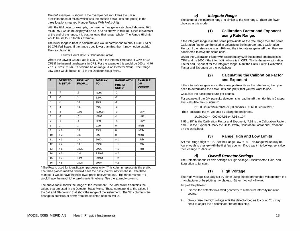
To understand the table below, imagine that the basic units and prefix which have been set from the above steps are in the three places marked 0 in the column marked Range With Prefix Units . The three spaces marked -1 in Range with units would have the next lower prefix, and the 3 spaces marked +1 would have the next higher prefix. The Meridian will automatically select the higher and lower prefix, but you have already set the starting point from the prefix-units/timebase settings made in the above steps.
There are 2 reasons for setting an upper range. The first is that when the instrument detects saturation or too many counts, it will make the Range Hi Limit the range that is shown with the overrange indicators. The other reason is to keep from switching to a high range if only a small portion of it can be used because of saturation or deadtime losses.
The maximum level has been calculated above. Find which range would be the maximum range based on the above calculations. Set the Range Hi Limit to the next higher range. Note the value on the worksheet.
MODEL 5085 MERIDIAN Health Physics Instruments 18
The GM example is shown in the Example column. It has the units-prefix/timebase of mR/h (which was the chosen basic units and prefix) in the three locations marked 0 under Range With Prefix-Units.
With the GM detector example, the maximum range as calculated above is 971 mR/h. 971 would be displayed on as XXX as shown in row 10. Since it is almost at the end of the range, it is best to leave that range whole. The Range Hi Limit would be set to +3 for this example.
The lower range is best to calculate and would correspond to about 600 CPM or 10 CPS Full Scale. If the range goes lower than this, then it may not be usable. The calculation is:
Lowest Count Rate x Calibration Factor
Where the Lowest Count Rate is 600 CPM if the internal timebase is CPM or 10 CPS if the internal timebase is in CPS. For the example this would be 600 x 4.76 x 1-4 = 0.286 mR/h. This would be on range -1 on Detector Setup. The Range Low Limit would be set to -1 in the Detector Setup Menu.
ff
DETECTODETECTOR SETUPR SETUP
DISPLAY DISPLAY FROM... FROM...
DISPLAY DISPLAY TO...TO...
RANGE WITH RANGE WITH
PREFIXPREFIX--UNITSUNITS 22
EXAMPLE EXAMPLE GM GM DetectorDetector
1 -7 .1 .999µ -2
2 -6 1 9.99µ -2
3 -5 10 99.9µ -2
4 -4 100 999µ -2
5 -3 .001 .00999 -1 uR/h
6 -2 .01 .0999 -1 uR/h
7 -1 .1 .999 -1 uR/h
8 0 1 9.99 0 mR/h
9 +1 10 99.9 0 mR/h
10 +2 100 999 0 mR/h
11 +3 1K 9990 +1 R/h
12 +4 10K 99.9K +1 R/h
13 +5 100K 999K +1 R/h
14 +6 1M 9.99M +2
15 +7 10M 99.9M +2
16 +8 100M 999M +2
1 The Row is used for identification purposes only. 2This column represents the prefix. The three places marked 0 would have the basic prefix-units/timebase. The three marked -1 would have the next lower prefix-units/timebase. The three marked +1 would have the next higher prefix-units/timebase. See the example column.
The above table shows the range of the instrument. The 2nd column contains the values that are used in the Detector Setup Menu. These correspond to the values in the 3rd and 4th column that show the range of the instrument. The 5th column is the change in prefix up or down from the selected nominal value.
c)c) Integrate RangeIntegrate Range The setup of the integrate range is similar to the rate range. There are fewer choices in this mode.
(1) Calibration Factor and Exponent using Rate Range.
If the integrate range is in the same prefix-units as the rate range then the same Calibration Factor can be used in calculating the integrate range Calibration Factor. If the rate range is in mR/h and the integrate range in mR then they are considered to have the same units.
Divide the Calibration Factor with Exponent by 60 if the internal timebase is in CPM and by 3600 if the internal timebase is in CPS. This is the new calibration Factor and Exponent for the integrate range. Mark the Units, Prefix, Calibration Factor and Exponent on the worksheet.
(2) Calculating the Calibration Factor and Exponent
If the integrate range is not in the same prefix-units as the rate range, then you need to determined the basic units and prefix that you will want to use.
Calculate the basic prefix-unit per counts.
For example, if the GM pancake detector is to read in mR then do this in 2 steps. First calculate the counts/mR.
(2100 Counts/Min/mR/h) x (60 min/hr) = 126,000 counts/mR
Then calculate the mR/counts by taking the reciprocal.
1/126,000 = .000,007,93 or 7.93 x 10⁻⁶
7.93 x 10⁻⁶ is the Calibration Factor and Exponent, 7.93 is the Calibration Factor, and -6 is the Exponent. Mark the Units, Prefix, Calibration Factor and Exponent on the worksheet.
(3) Range High and Low Limits Set the Range High to +8. Set the Range Low to -4. This range will usually be low enough to change with the first few counts. If you want it to be less sensitive, then change to -3 or -2.
d)d) Overall Detector SettingsOverall Detector Settings The Detector needs its own settings of High Voltage, Discriminator, Gain, and Saturation to function.
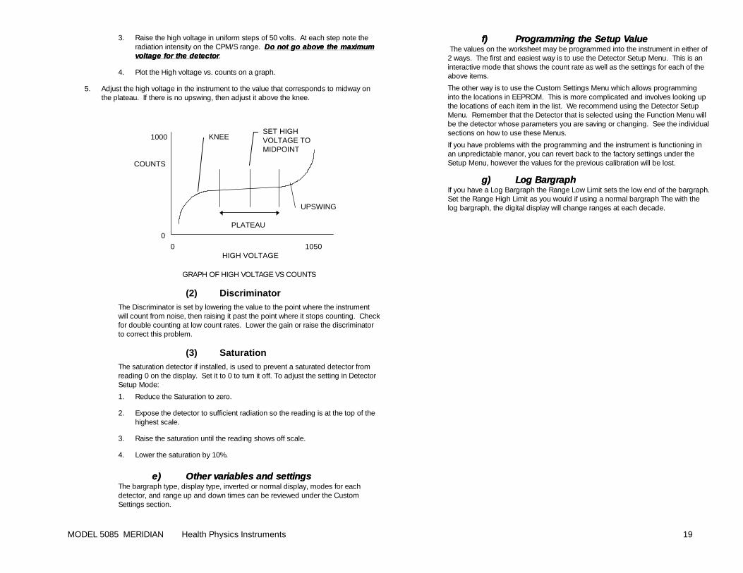
(1) High Voltage The High voltage is usually set by either using the recommended voltage from the manufacturer or by plotting the plateau. Either method will work.
To plot the plateau:
1. Expose the detector in a fixed geometry to a medium intensity radiation source.
2. Slowly raise the high voltage until the detector begins to count. You may need to adjust the discriminator before this step.
MODEL 5085 MERIDIAN Health Physics Instruments 19
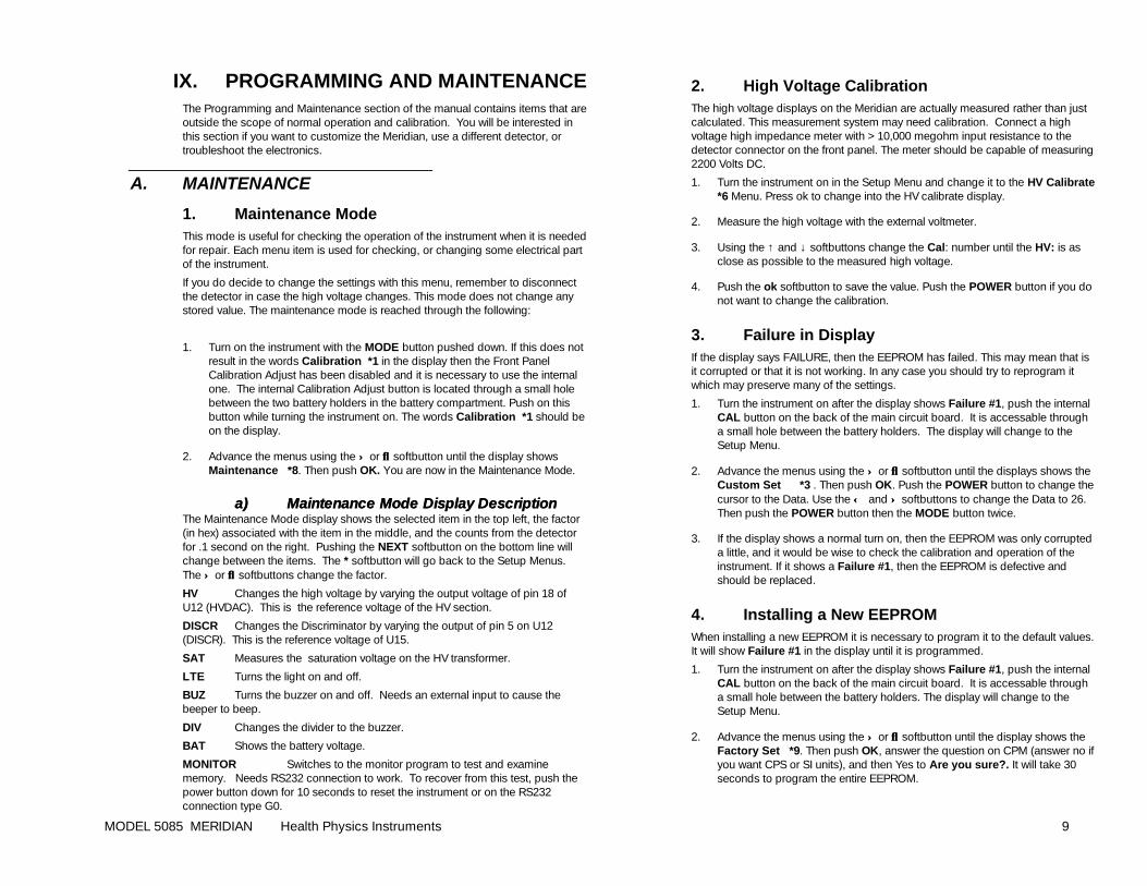
3. Raise the high voltage in uniform steps of 50 volts. At each step note the radiation intensity on the CPM/S range. Do not go above the maximum Do not go above the maximum voltage for the detvoltage for the detectorector .
4. Plot the High voltage vs. counts on a graph.
5. Adjust the high voltage in the instrument to the value that corresponds to midway on the plateau. If there is no upswing, then adjust it above the knee.
KNEE
UPSWING
PLATEAU
0 1050 HIGH VOLTAGE
1000
COUNTS
0
SET HIGHVOLTAGE TOMIDPOINT
GRAPH OF HIGH VOLTAGE VS COUNTS
(2) Discriminator The Discriminator is set by lowering the value to the point where the instrument will count from noise, then raising it past the point where it stops counting. Check for double counting at low count rates. Lower the gain or raise the discriminator to correct this problem.
(3) Saturation The saturation detector if installed, is used to prevent a saturated detector from reading 0 on the display. Set it to 0 to turn it off. To adjust the setting in Detector Setup Mode:
1. Reduce the Saturation to zero.
2. Expose the detector to sufficient radiation so the reading is at the top of the highest scale.
3. Raise the saturation until the reading shows off scale.
4. Lower the saturation by 10%.
e)e) Other variables andOther variables and settings settings The bargraph type, display type, inverted or normal display, modes for each detector, and range up and down times can be reviewed under the Custom Settings section.
f)f) Programming the Setup ValueProgramming the Setup Value The values on the worksheet may be programmed into the instrument in either of 2 ways. The first and easiest way is to use the Detector Setup Menu. This is an interactive mode that shows the count rate as well as the settings for each of the above items.
The other way is to use the Custom Settings Menu which allows programming into the locations in EEPROM. This is more complicated and involves looking up the locations of each item in the list. We recommend using the Detector Setup Menu. Remember that the Detector that is selected using the Function Menu will be the detector whose parameters you are saving or changing. See the individual sections on how to use these Menus.
If you have problems with the programming and the instrument is functioning in an unpredictable manor, you can revert back to the factory settings under the Setup Menu, however the values for the previous calibration will be lost.
g)g) Log BargraphLog Bargraph If you have a Log Bargraph the Range Low Limit sets the low end of the bargraph. Set the Range High Limit as you would if using a normal bargraph The with the log bargraph, the digital display will change ranges at each decade.
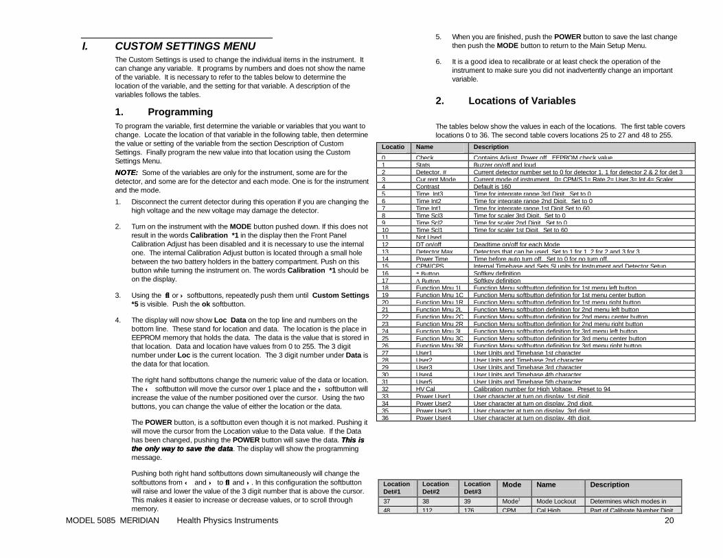
MODEL 5085 MERIDIAN Health Physics Instruments 20
I. CUSTOM SETTINGS MENU The Custom Settings is used to change the individual items in the instrument. It can change any variable. It programs by numbers and does not show the name of the variable. It is necessary to refer to the tables below to determine the location of the variable, and the setting for that variable. A description of the variables follows the tables.
1. Programming To program the variable, first determine the variable or variables that you want to change. Locate the location of that variable in the following table, then determine the value or setting of the variable from the section Description of Custom Settings. Finally program the new value into that location using the Custom Settings Menu.
NNOTE:OTE: Some of the variables are only for the instrument, some are for the detector, and some are for the detector and each mode. One is for the instrument and the mode.
1. Disconnect the current detector during this operation if you are changing the high voltage and the new voltage may damage the detector.
2. Turn on the instrument with the MODE button pushed down. If this does not result in the words Calibration *1 in the display then the Front Panel Calibration Adjust has been disabled and it is necessary to use the internal one. The internal Calibration Adjust button is located through a small hole between the two battery holders in the battery compartment. Push on this button while turning the instrument on. The words Calibration *1 should be on the display.
3. Using the ↓↓ or ↑↑ softbuttons, repeatedly push them until Custom Settings *5 is visible. Push the ok softbutton.
4. The display will now show Loc Data on the top line and numbers on the bottom line. These stand for location and data. The location is the place in EEPROM memory that holds the data. The data is the value that is stored in that location. Data and location have values from 0 to 255. The 3 digit number under Loc is the current location. The 3 digit number under Data is the data for that location.
The right hand softbuttons change the numeric value of the data or location. The ←← softbutton will move the cursor over 1 place and the ↑↑ softbutton will increase the value of the number positioned over the cursor. Using the two buttons, you can change the value of either the location or the data.
The POWER button, is a softbutton even though it is not marked. Pushing it will move the cursor from the Location value to the Data value. If the Data has been changed, pushing the POWER button will save the data. This is This is the only way to save the datathe only way to save the data. The display will show the programming message.
Pushing both right hand softbuttons down simultaneously will change the softbuttons from ←← and ↑↑ to ↓↓ and ↑↑. In this configuration the softbutton will raise and lower the value of the 3 digit number that is above the cursor. This makes it easier to increase or decrease values, or to scroll through memory.
5. When you are finished, push the POWER button to save the last change then push the MODE button to return to the Main Setup Menu.
6. It is a good idea to recalibrate or at least check the operation of the instrument to make sure you did not inadvertently change an important variable.
2. Locations of Variables
The tables below show the values in each of the locations. The first table covers locations 0 to 36. The second table covers locations 25 to 27 and 48 to 255.
Location
Name Description
0 Check Contains Adjust, Power off , EEPROM check value 1 Stats Buzzer on/off and loud 2 Detector. # Current detector number set to 0 for detector 1, 1 for detector 2 & 2 for det 3 3 Cur rent Mode Current mode of instrument. 0=CPM/S,1=Rate,2=User,3=Int,4=Scaler 4 Contrast Default is 160 5 Time Int3 Time for integrate range 3rd Digit. Set to 0 6 Time Int2 Time for integrate range 2nd Digit. Set to 0 7 Time Int1 Time for integrate range 1st Digit Set to 60 8 Time Scl3 Time for scaler 3rd Digit. Set to 0 9 Time Scl2 Time for scaler 2nd Digit. Set to 0 10 Time Scl1 Time for scaler 1st Digit. Set to 60 11 Not Used 12 DT on/off Deadtime on/off for each Mode 13 Detector Max Detectors that can be used. Set to 1 for 1, 2 for 2 and 3 for 3 14 Power Time Time before auto turn off. Set to 0 for no turn off. 15 CPM/CPS Internal Timebase and Sets SI units for Instrument and Detector Setup. 16 ∗ Button Softkey definition 17 ∆ Button Softkey definition 18 Function Mnu 1L Function Menu softbutton definition for 1st menu left button 19 Function Mnu 1C Function Menu softbutton definition for 1st menu center button 20 Function Mnu 1R Function Menu softbutton definition for 1st menu right button 21 Function Mnu 2L Function Menu softbutton definition for 2nd menu left button 22 Function Mnu 2C Function Menu softbutton definition for 2nd menu center button 23 Function Mnu 2R Function Menu softbutton definition for 2nd menu right button 24 Function Mnu 3L Function Menu softbutton definition for 3rd menu left button 25 Function Mnu 3C Function Menu softbutton definition for 3rd menu center button 26 Function Mnu 3R Function Menu softbutton definition for 3rd menu right button 27 User1 User Units and Timebase 1st character 28 User2 User Units and Timebase 2nd character 29 User3 User Units and Timebase 3rd character 30 User4 User Units and Timebase 4th character 31 User5 User Units and Timebase 5th character 32 HV Cal Calibration number for High Voltage. Preset to 94 33 Power User1 User character at turn on display. 1st digit. 34 Power User2 User character at turn on display. 2nd digit. 35 Power User3 User character at turn on display. 3rd digit. 36 Power User4 User character at turn on display. 4th digit.
Location Det#1
Location Det#2
Location Det#3
Mode Name Description
37 38 39 Mode1 Mode Lockout Determines which modes in use 48 112 176 CPM Cal High Part of Calibrate Number Digit
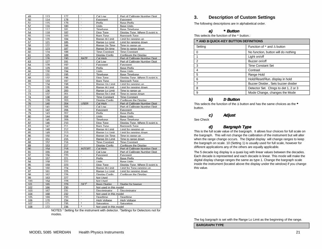
MODEL 5085 MERIDIAN Health Physics Instruments 21
49 113 177 ‘ Cal Low Part of Calibrate Number Digit 50 114 178 ‘ Exponent Exponent 51 115 179 ‘ Prefix Base Prefix 52 116 180 ‘ Units Base Units 53 117 181 ‘ Timebase Base Timebase 54 118 182 ‘ Disp Type Display Type, Where D.point is 55 119 183 ‘ Barg Type Bargraph Type 56 120 184 ‘ Range Hi Limit Limit for ranging up 57 121 185 ‘ Range Lo Limit Limit for ranging down 58 122 186 ‘ Range Up Time Time to range up 59 123 187 ‘ Range Dn time Time to range down 60 124 188 ‘ Time Constant Time Constant 61 125 189 ‘ Display Confg Configure the Display 62 126 190 RATE Cal High Part of Calibrate Number Digit 63 127 191 ‘ Cal Low Part of Calibrate Number Digit 64 128 192 ‘ Exponent Exponent 65 129 193 ‘ Prefix Base Prefix 66 130 194 ‘ Units Base Units 67 131 195 ‘ Timebase Base Timebase 68 132 196 ‘ Disp Type Display Type, Where D point is 69 133 197 ‘ Barg Type Bargraph Type 70 134 198 ‘ Range Up Limit Limit for ranging up 71 135 199 ‘ Range Hi Limit Limit for ranging down 72 136 200 ‘ Range Lo Limit Time to range up 73 137 201 ‘ Range Dn Limit Time to range down 74 138 202 ‘ Time Constant Time Constant 75 139 203 ‘ Display Confg Configure the Display 76 140 204 USER Cal High Part of Calibrate Number Digit 77 141 205 ‘ Cal Low Part of Calibrate Number Digit 78 142 206 ‘ Exponent Exponent 79 143 207 ‘ Prefix Base Prefix 80 144 208 ‘ Units Base Units 81 145 209 ‘ Timebase Base Timebase 82 146 210 ‘ Disp Type Display Type, Where D point is 83 147 211 ‘ Barg Type Bargraph Type 84 148 212 ‘ Range Hi Limit Limit for ranging up 85 149 213 ‘ Range Lo Limit Limit for ranging down 86 150 214 ‘ Range Up Time Time to range up 87 151 215 ‘ Range Dn Limit Time to range down 88 152 216 ‘ Time Constant Time Constant 89 153 217 ‘ Display Confg Configure the Display 90 154 218 INTGRT Cal High Part of Calibrate Number Digit 91 155 219 ‘ Cal Low Part of Calibrate Number Digit 92 156 220 ‘ Exponent Exponent 93 157 221 ‘ Prefix Base Prefix 94 158 222 ‘ Units Base Units 95 159 223 ‘ Disp Type Display Type, Where D point is 96 160 224 ‘ Range Hi Limit Limit for Type ranging up 97 161 225 ‘ Range Lo Limit Limit for ranging down 98 162 226 ‘ Display Confg Configure the Display 99 163 227 Not Used 100 164 228 Not Used 101 165 229 DET2 Beep Divider Divider for beeper 102 166 230 Not used in this model 103 167 231 ‘ Discriminator Discriminator 104 168 232 ‘ Not used in this model 105 169 233 ‘ Deadtime Deadtime 106 170 234 ‘ High Voltage High Voltage 107 171 235 ‘‘ Saturation Saturation 108 172 236 ‘‘ Not used in this model
NOTES 1 Setting for the instrument with detector. 2Settings for Detectors not for modes.
3. Description of Custom Settings The following descriptions are in alphabetical order.
a)a) ∗∗ Button Button This selects the function of the ∗ button.:
∗∗ AND ∆∆ QUICK-KEY BUTTON DEFINITIONS
Setting Function of ∗ and ∆ button
0 No function, button will do nothing 1 Light on/off 2 Buzzer on/off 3 Time Constant Set 4 Contrast 5 Range Hold 6 Hold/Reset/Run. display in hold 7 Buzzer Divider., Sets buzzer divider 8 Detector Set. Chngs to det 1, 2 or 3 9 Mode Change, changes the Mode
b)b) ∆∆ Button Button This selects the function of the ∆ button and has the same choices as the ∗∗ button.
c)c) AdjustAdjust See Check
d)d) Bargraph TypeBargraph Type This is the full scale value of the bargraph. It allows four choices for full scale on the bargraph. This will not change the calibration of the instrument but will alter when the range change occurs. The Digital display will change ranges to keep the bargraph on scale. 10 (Setting 1) is usually used for full scale, however for different applications any of the others are equally applicable.
The 5 decade log display is a quasi log with linear values between the decades. Each decade is represented and each decade is linear. This mode will make the digital display change ranges the same as type 1. Change the bargraph scale inside the instrument (located above the display under the window) if you change this value.
The log bargraph is set with the Range Lo Limit as the beginning of the range.
BARGRAPH TYPE
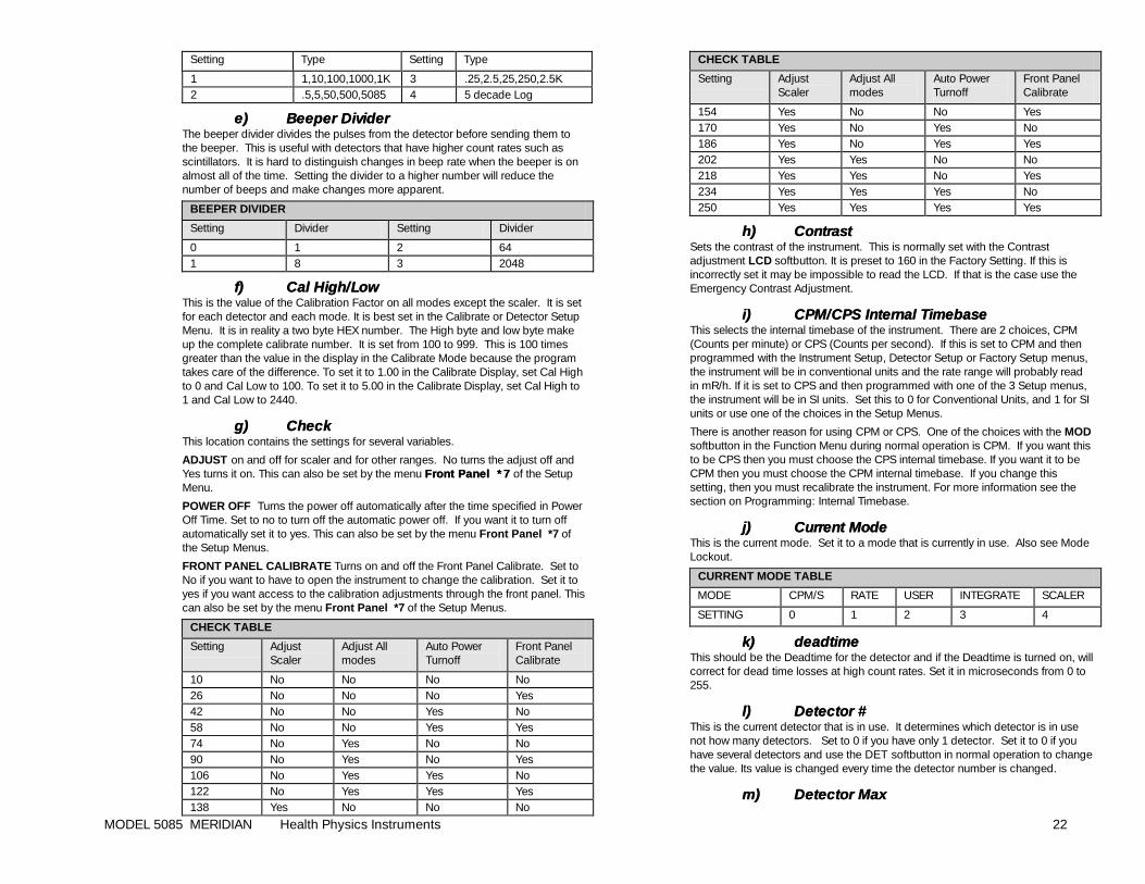
MODEL 5085 MERIDIAN Health Physics Instruments 22
Setting Type Setting Type
1 1,10,100,1000,1K 3 .25,2.5,25,250,2.5K 2 .5,5,50,500,5085 4 5 decade Log
e)e) Beeper DividerBeeper Divider The beeper divider divides the pulses from the detector before sending them to the beeper. This is useful with detectors that have higher count rates such as scintillators. It is hard to distinguish changes in beep rate when the beeper is on almost all of the time. Setting the divider to a higher number will reduce the number of beeps and make changes more apparent.
BEEPER DIVIDER
Setting Divider Setting Divider
0 1 2 64 1 8 3 2048
f)f) Cal High/LowCal High/Low This is the value of the Calibration Factor on all modes except the scaler. It is set for each detector and each mode. It is best set in the Calibrate or Detector Setup Menu. It is in reality a two byte HEX number. The High byte and low byte make up the complete calibrate number. It is set from 100 to 999. This is 100 times greater than the value in the display in the Calibrate Mode because the program takes care of the difference. To set it to 1.00 in the Calibrate Display, set Cal High to 0 and Cal Low to 100. To set it to 5.00 in the Calibrate Display, set Cal High to 1 and Cal Low to 2440.
g)g) CheckCheck This location contains the settings for several variables.
ADJUST on and off for scaler and for other ranges. No turns the adjust off and Yes turns it on. This can also be set by the menu Front Panel *7Front Panel *7 of the Setup Menu.
POWER OFF Turns the power off automatically after the time specified in Power Off Time. Set to no to turn off the automatic power off. If you want it to turn off automatically set it to yes. This can also be set by the menu Front Panel *7 of the Setup Menus.
FRONT PANEL CALIBRATE Turns on and off the Front Panel Calibrate. Set to No if you want to have to open the instrument to change the calibration. Set it to yes if you want access to the calibration adjustments through the front panel. This can also be set by the menu Front Panel *7 of the Setup Menus.
CHECK TABLE
Setting Adjust Scaler
Adjust All modes
Auto Power Turnoff
Front Panel Calibrate
10 No No No No 26 No No No Yes 42 No No Yes No 58 No No Yes Yes 74 No Yes No No 90 No Yes No Yes 106 No Yes Yes No 122 No Yes Yes Yes 138 Yes No No No
CHECK TABLE
Setting Adjust Scaler
Adjust All modes
Auto Power Turnoff
Front Panel Calibrate
154 Yes No No Yes 170 Yes No Yes No 186 Yes No Yes Yes 202 Yes Yes No No 218 Yes Yes No Yes 234 Yes Yes Yes No 250 Yes Yes Yes Yes
h)h) ContrastContrast Sets the contrast of the instrument. This is normally set with the Contrast adjustment LCD softbutton. It is preset to 160 in the Factory Setting. If this is incorrectly set it may be impossible to read the LCD. If that is the case use the Emergency Contrast Adjustment.
i)i) CPM/CPS Internal TimebaseCPM/CPS Internal Timebase This selects the internal timebase of the instrument. There are 2 choices, CPM (Counts per minute) or CPS (Counts per second). If this is set to CPM and then programmed with the Instrument Setup, Detector Setup or Factory Setup menus, the instrument will be in conventional units and the rate range will probably read in mR/h. If it is set to CPS and then programmed with one of the 3 Setup menus, the instrument will be in SI units. Set this to 0 for Conventional Units, and 1 for SI units or use one of the choices in the Setup Menus.
There is another reason for using CPM or CPS. One of the choices with the MOD softbutton in the Function Menu during normal operation is CPM. If you want this to be CPS then you must choose the CPS internal timebase. If you want it to be CPM then you must choose the CPM internal timebase. If you change this setting, then you must recalibrate the instrument. For more information see the section on Programming: Internal Timebase.
j)j) Current ModeCurrent Mode This is the current mode. Set it to a mode that is currently in use. Also see Mode Lockout.
CURRENT MODE TABLE
MODE CPM/S RATE USER INTEGRATE SCALER
SETTING 0 1 2 3 4
k)k) deadtimedeadtime This should be the Deadtime for the detector and if the Deadtime is turned on, will correct for dead time losses at high count rates. Set it in microseconds from 0 to 255.
l)l) Detector #Detector # This is the current detector that is in use. It determines which detector is in use not how many detectors. Set to 0 if you have only 1 detector. Set it to 0 if you have several detectors and use the DET softbutton in normal operation to change the value. Its value is changed every time the detector number is changed.
m)m) Detector MaxDetector Max
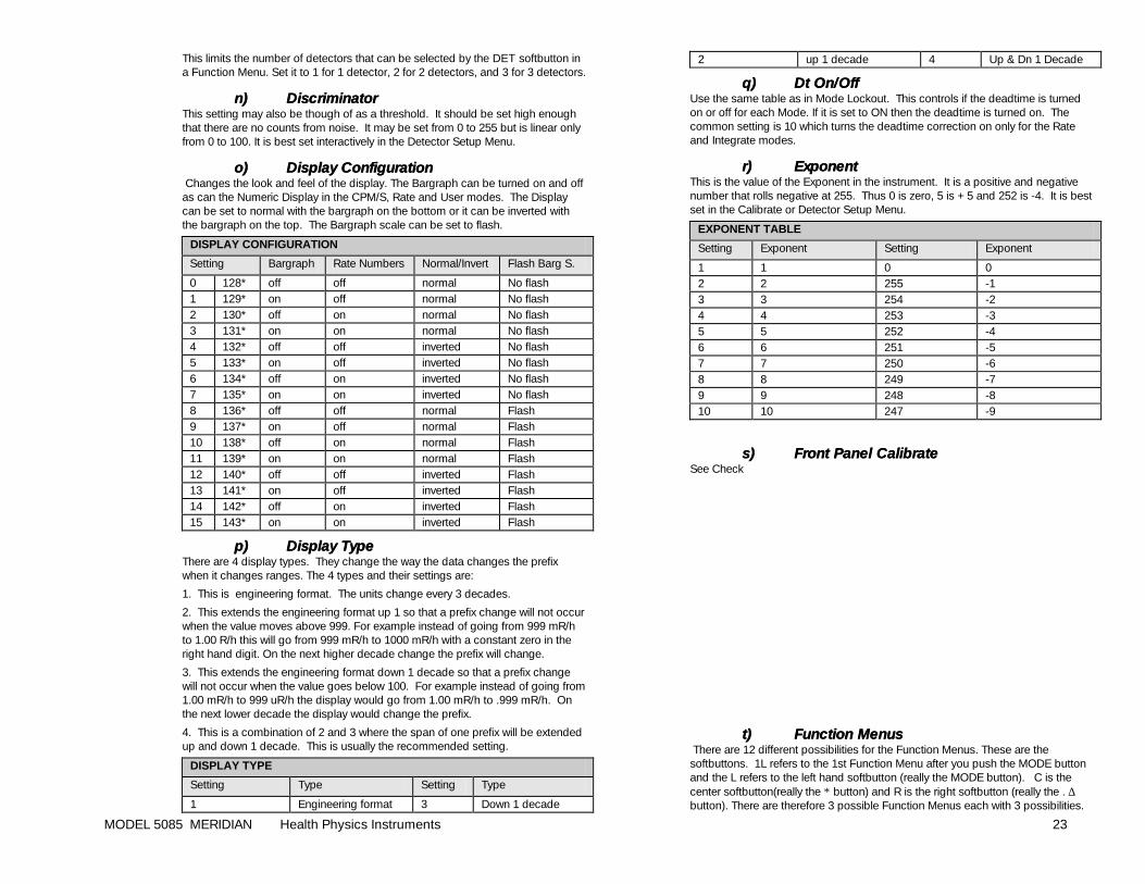
MODEL 5085 MERIDIAN Health Physics Instruments 23
This limits the number of detectors that can be selected by the DET softbutton in a Function Menu. Set it to 1 for 1 detector, 2 for 2 detectors, and 3 for 3 detectors.
n)n) DiscriminatorDiscriminator This setting may also be though of as a threshold. It should be set high enough that there are no counts from noise. It may be set from 0 to 255 but is linear only from 0 to 100. It is best set interactively in the Detector Setup Menu.
o)o) Display ConfigurationDisplay Configuration Changes the look and feel of the display. The Bargraph can be turned on and off as can the Numeric Display in the CPM/S, Rate and User modes. The Display can be set to normal with the bargraph on the bottom or it can be inverted with the bargraph on the top. The Bargraph scale can be set to flash.
DISPLAY CONFIGURATION
Setting Bargraph Rate Numbers Normal/Invert Flash Barg S.
0 128* off off normal No flash 1 129* on off normal No flash 2 130* off on normal No flash 3 131* on on normal No flash 4 132* off off inverted No flash 5 133* on off inverted No flash 6 134* off on inverted No flash 7 135* on on inverted No flash 8 136* off off normal Flash 9 137* on off normal Flash 10 138* off on normal Flash 11 139* on on normal Flash 12 140* off off inverted Flash 13 141* on off inverted Flash 14 142* off on inverted Flash 15 143* on on inverted Flash
p)p) Display TypeDisplay Type There are 4 display types. They change the way the data changes the prefix when it changes ranges. The 4 types and their settings are:
1. This is engineering format. The units change every 3 decades.
2. This extends the engineering format up 1 so that a prefix change will not occur when the value moves above 999. For example instead of going from 999 mR/h to 1.00 R/h this will go from 999 mR/h to 1000 mR/h with a constant zero in the right hand digit. On the next higher decade change the prefix will change.
3. This extends the engineering format down 1 decade so that a prefix change will not occur when the value goes below 100. For example instead of going from 1.00 mR/h to 999 uR/h the display would go from 1.00 mR/h to .999 mR/h. On the next lower decade the display would change the prefix.
4. This is a combination of 2 and 3 where the span of one prefix will be extended up and down 1 decade. This is usually the recommended setting.
DISPLAY TYPE
Setting Type Setting Type
1 Engineering format 3 Down 1 decade
2 up 1 decade 4 Up & Dn 1 Decade
q)q) Dt On/OffDt On/Off Use the same table as in Mode Lockout. This controls if the deadtime is turned on or off for each Mode. If it is set to ON then the deadtime is turned on. The common setting is 10 which turns the deadtime correction on only for the Rate and Integrate modes.
r)r) ExponentExponent This is the value of the Exponent in the instrument. It is a positive and negative number that rolls negative at 255. Thus 0 is zero, 5 is +5 and 252 is -4. It is best set in the Calibrate or Detector Setup Menu.
EXPONENT TABLE
Setting Exponent Setting Exponent
1 1 0 0 2 2 255 -1 3 3 254 -2 4 4 253 -3 5 5 252 -4 6 6 251 -5 7 7 250 -6 8 8 249 -7 9 9 248 -8 10 10 247 -9
s)s) Front Panel CalibrateFront Panel Calibrate See Check
t)t) Function MenusFunction Menus There are 12 different possibilities for the Function Menus. These are the softbuttons. 1L refers to the 1st Function Menu after you push the MODE button and the L refers to the left hand softbutton (really the MODE button). C is the center softbutton(really the ∗ button) and R is the right softbutton (really the . ∆ button). There are therefore 3 possible Function Menus each with 3 possibilities.
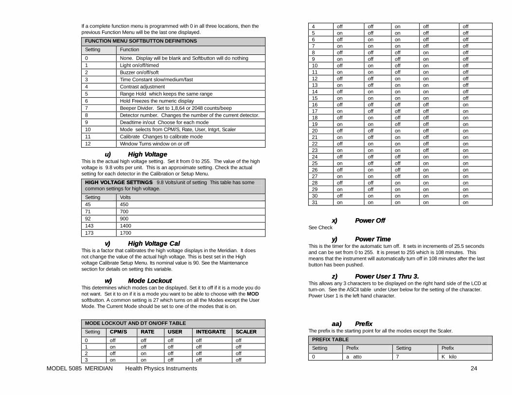
MODEL 5085 MERIDIAN Health Physics Instruments 24
If a complete function menu is programmed with 0 in all three locations, then the previous Function Menu will be the last one displayed.
FUNCTION MENU SOFTBUTTON DEFINITIONS
Setting Function
0 None. Display will be blank and Softbutton will do nothing 1 Light on/off/timed 2 Buzzer on/off/soft 3 Time Constant slow/medium/fast 4 Contrast adjustment 5 Range Hold which keeps the same range 6 Hold Freezes the numeric display 7 Beeper Divider. Set to 1,8,64 or 2048 counts/beep 8 Detector number. Changes the number of the current detector. 9 Deadtime in/out Choose for each mode 10 Mode selects from CPM/S, Rate, User, Intgrt, Scaler 11 Calibrate Changes to calibrate mode 12 Window Turns window on or off
u)u) High VoltageHigh Voltage This is the actual high voltage setting. Set it from 0 to 255. The value of the high voltage is 9.8 volts per unit. This is an approximate setting. Check the actual setting for each detector in the Calibration or Setup Menu.
HIGH VOLTAGE SEHIGH VOLTAGE SETTINGSTTINGS 9.8 Volts/unit of setting This table has some common settings for high voltage.
Setting Volts 45 450 71 700 92 900 143 1400 173 1700
v)v) High Voltage CalHigh Voltage Cal This is a factor that calibrates the high voltage displays in the Meridian. It does not change the value of the actual high voltage. This is best set in the High voltage Calibrate Setup Menu. Its nominal value is 90. See the Maintenance section for details on setting this variable.
w)w) Mode LockoutMode Lockout This determines which modes can be displayed. Set it to off if it is a mode you do not want. Set it to on if it is a mode you want to be able to choose with the MOD softbutton. A common setting is 27 which turns on all the Modes except the User Mode. The Current Mode should be set to one of the modes that is on.
MODE LOCKOUT AND DT ON/OFF TABLE
Setting CPM/S CPM/S RATERATE USERUSER INTEGRATEINTEGRATE SCALERSCALER
0 off off off off off 1 on off off off off 2 off on off off off 3 on on off off off
4 off off on off off 5 on off on off off 6 off on on off off 7 on on on off off 8 off off off on off 9 on off off on off 10 off on off on off 11 on on off on off 12 off off on on off 13 on off on on off 14 off on on on off 15 on on on on off 16 off off off off on 17 on off off off on 18 off on off off on 19 on on off off on 20 off off on off on 21 on off on off on 22 off on on off on 23 on on on off on 24 off off off on on 25 on off off on on 26 off on off on on 27 on on off on on 28 off off on on on 29 on off on on on 30 off on on on on 31 on on on on on
x)x) Power OffPower Off See Check
y)y) Power TimePower Time This is the timer for the automatic turn off. It sets in increments of 25.5 seconds and can be set from 0 to 255. It is preset to 255 which is 108 minutes. This means that the instrument will automatically turn off in 108 minutes after the last button has been pushed.
z)z) Power User 1 Thru 3. Power User 1 Thru 3. This allows any 3 characters to be displayed on the right hand side of the LCD at turn-on. See the ASCII table under User below for the setting of the character. Power User 1 is the left hand character.
aa)aa) PrefixPrefix The prefix is the starting point for all the modes except the Scaler.
PREFIX TABLE
Setting Prefix Setting Prefix
0 a atto 7 K kilo
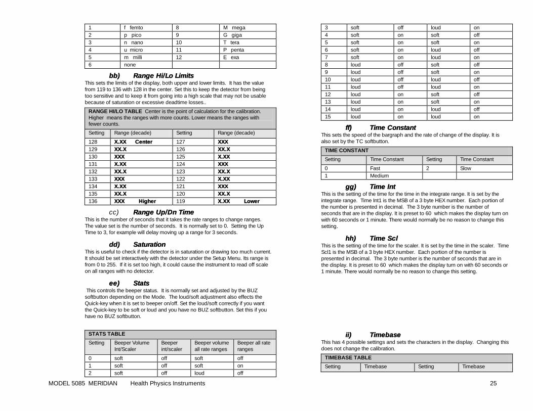
MODEL 5085 MERIDIAN Health Physics Instruments 25
1 f femto 8 M mega 2 p pico 9 G giga 3 n nano 10 T tera 4 u micro 11 P penta 5 m milli 12 E exa 6 none
bb)bb) Range Hi/Lo LimitsRange Hi/Lo Limits This sets the limits of the display, both upper and lower limits. It has the value from 119 to 136 with 128 in the center. Set this to keep the detector from being too sensitive and to keep it from going into a high scale that may not be usable because of saturation or excessive deadtime losses..
RANGE HI/LO TABLE Center is the point of calculation for the calibration. Higher means the ranges with more counts. Lower means the ranges with fewer counts.
Setting Range (decade) Setting Range (decade)
128 X.XX CenterX.XX Center 127 XXXXXX 129 XX.XXX.X 126 XX.XXX.X 130 XXXXXX 125 X.XXX.XX 131 X.XX X.XX 124 XXXXXX 132 XX.XXX.X 123 XX.XXX.X 133 XXXXXX 122 X.XXX.XX 134 X.XXX.XX 121 XXXXXX 135 XX.XXX.X 120 XX.XXX.X 136 XXX Higher XXX Higher 119 X.XX LowerX.XX Lower
cc) Range Up/Dn TimeRange Up/Dn Time This is the number of seconds that it takes the rate ranges to change ranges. The value set is the number of seconds. It is normally set to 0. Setting the Up Time to 3, for example will delay moving up a range for 3 seconds.
dd)dd) SaturationSaturation This is useful to check if the detector is in saturation or drawing too much current. It should be set interactively with the detector under the Setup Menu. Its range is from 0 to 255. If it is set too high, it could cause the instrument to read off scale on all ranges with no detector.
ee)ee) StatsStats This controls the beeper status. It is normally set and adjusted by the BUZ softbutton depending on the Mode. The loud/soft adjustment also effects the Quick-key when it is set to beeper on/off. Set the loud/soft correctly if you want the Quick-key to be soft or loud and you have no BUZ softbutton. Set this if you have no BUZ softbutton.
STATS TABLE
Setting Beeper Volume Int/Scaler
Beeper int/scaler
Beeper volume all rate ranges
Beeper all rate ranges
0 soft off soft off 1 soft off soft on 2 soft off loud off
3 soft off loud on 4 soft on soft off 5 soft on soft on 6 soft on loud off 7 soft on loud on 8 loud off soft off 9 loud off soft on 10 loud off loud off 11 loud off loud on 12 loud on soft off 13 loud on soft on 14 loud on loud off 15 loud on loud on
ff)ff) Time ConstantTime Constant This sets the speed of the bargraph and the rate of change of the display. It is also set by the TC softbutton.
TIME CONSTANT
Setting Time Constant Setting Time Constant
0 Fast 2 Slow 1 Medium
gg)gg) Time IntTime Int This is the setting of the time for the time in the integrate range. It is set by the integrate range. Time Int1 is the MSB of a 3 byte HEX number. Each portion of the number is presented in decimal. The 3 byte number is the number of seconds that are in the display. It is preset to 60 which makes the display turn on with 60 seconds or 1 minute. There would normally be no reason to change this setting.
hh)hh) Time ScTime Scll This is the setting of the time for the scaler. It is set by the time in the scaler. Time Scl1 is the MSB of a 3 byte HEX number. Each portion of the number is presented in decimal. The 3 byte number is the number of seconds that are in the display. It is preset to 60 which makes the display turn on with 60 seconds or 1 minute. There would normally be no reason to change this setting.
i i)ii) TimebaseTimebase This has 4 possible settings and sets the characters in the display. Changing this does not change the calibration.
TIMEBASE TABLE
Setting Timebase Setting Timebase

MODEL 5085 MERIDIAN Health Physics Instruments 26
0 none� 2 /m 1 /h 3 /s
jj)jj) UnitsUnits The units select which units are used in all modes except the Scaler..
UNITS TABLE
Setting Units Setting Units
0 cnt 6 Gy 1 REM 7 dis 2 rad 8 CPM 3 R 9 CPS 4 Sv 10 user 1 thru 5 5 Bq
kk)kk) User 1 Thru 5User 1 Thru 5 This allows any characters to be used for the units and timebase. If user is chosen under Units then these 5 characters will occupy the space for units and timebase. They are normal ASCII characters. Each one needs to be programmed with its own character. User 1 is the left hand character.
ASCII CHARACTER TABLE
#1 CH2 #1 CH2 #1 CH2 #1 CH2
32 (space 48 0 64 @ 80 P 33 ! 49 1 65 A 81 Q 34 “ 50 2 66 B 82 R 35 # 51 3 67 C S 36 $ 52 4 68 D 84 T 37 % 53 5 69 E 85 U 38 & 54 6 70 F 86 V 39 ‘ 55 7 71 G 87 W 40 ( 56 8 72 H 88 X 41 ) 57 9 73 I 89 Y 42 * 58 : 74 J 90 Z 43 + 59 ; 75 K 91 [ 44 , 60 <� 76 L 92 Y 45 - 61 = 77 M 93 ] 46 . 62 > 78 N 94 ^ 47 / 63 ? 79 O 95 _
1 Setting, 2 Character
There are settings from 0 to 255, however they are not normal ASCII characters. If you need a strange character, please contact the factory.
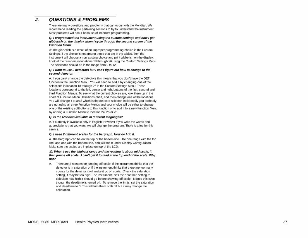
MODEL 5085 MERIDIAN Health Physics Instruments 27
J. QUESTIONS & PROBLEMS There are many questions and problems that can occur with the Meridian. We recommend reading the pertaining sections to try to understand the instrument. Most problems will occur because of incorrect programming.
Q: I programmed the instrument using the custom settings and now I get gibberish on the display when I cycle through the second screen of the Function Menu.
A: The gibberish is a result of an improper programming choice in the Custom Settings. If the choice is not among those that are in the tables, then the instrument will choose a non existing choice and print gibberish on the display. Look at the numbers in locations 18 through 26 using the Custom Settings Menu. The selections should be in the range from 0 to 12.
Q: I want to use 2 detectors but I can’t figure out how to change to the second detector.
A: If you can’t change the detectors this means that you don’t have the DET function in the Function Menu. You will need to add it by changing one of the selections in location 18 through 26 in the Custom Settings Menu. These locations correspond to the left, center and right buttons of the first, second and third Function Menus. To see what the current choices are, look them up in the chart of Function Menu Definitions chart, and then change one of the locations. You will change it to an 8 which is the detector selector. Incidentally you probably are not using all three Function Menus and your choice will be either to change one of the existing softbuttons to this function or to add it to a new Function Menu by adding a Function Menu to location 24, 25 or 26.
Q: Is the Meridian available in different languages?
A. It currently is available only in English. However if you write the words and abbreviations that you want, we will change the program. There is a fee for this service.
Q: I need 2 different scales for the bargraph. How do I do it.
A. The bargraph can be on the top or the bottom line. Use one range with the top line, and one with the bottom line. You will find it under Display Configuration. Make sure the scales are in place on top of the LCD.
.Q: When I use the highest range and the reading is about mid scale, it then jumps off scale. I can’t get it to read at the top end of the scale. Why not?
A. There are 2 reasons for jumping off scale. If the instrument thinks that the detector is in saturation or if the instrument thinks that there are too many counts for the detector it will make it go off scale. Check the saturation setting, it may be too high. The instrument uses the deadtime setting to calculate how high it should go before showing off scale. It does this even though the deadtime is turned off. To remove the limits, set the saturation and deadtime to 0. This will turn them both off but it may change the calibration.
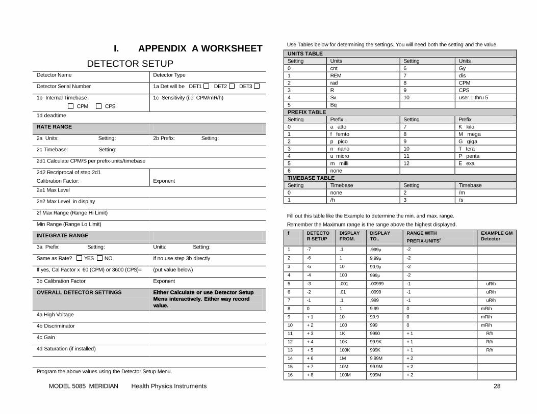
MODEL 5085 MERIDIAN Health Physics Instruments 28
I. APPENDIX A WORKSHEET
DETECTOR SETUP Detector Name Detector Type
Detector Serial Number 1a Det will be DET1 DET2 DET3
1b Internal Timebase
CPM CPS
1c Sensitivity (i.e. CPM/mR/h)
1d deadtime
RATE RANGE
2a Units: Setting: 2b Prefix: Setting:
2c Timebase: Setting:
2d1 Calculate CPM/S per prefix-units/timebase
2d2 Recriprocal of step 2d1
Calibration Factor:
Exponent
2e1 Max Level
2e2 Max Level in display
2f Max Range (Range Hi Limit)
Min Range (Range Lo Limit)
INTEGRATE RANGE
3a Prefix: Setting: Units: Setting:
Same as Rate? YES NO If no use step 3b directly
If yes, Cal Factor x 60 (CPM) or 3600 (CPS)= (put value below)
3b Calibration Factor Exponent
OVERALL DETECTOR SETTINGS Either Calculate or use Detector Setup Either Calculate or use Detector Setup Menu interactively. Either way record Menu interactively. Either way record value.value.
4a High Voltage
4b Discriminator
4c Gain
4d Saturation (if installed)
Program the above values using the Detector Setup Menu.
Use Tables below for determining the settings. You will need both the setting and the value.
UNITS TABLE Setting Units Setting Units 0 cnt 6 Gy 1 REM 7 dis 2 rad 8 CPM 3 R 9 CPS 4 Sv 10 user 1 thru 5 5 Bq PREFIX TABLE Setting Prefix Setting Prefix 0 a atto 7 K kilo 1 f femto 8 M mega 2 p pico 9 G giga 3 n nano 10 T tera 4 u micro 11 P penta 5 m milli 12 E exa 6 none TIMEBASE TABLE Setting Timebase Setting Timebase 0 none 2 /m 1 /h 3 /s
Fill out this table like the Example to determine the min. and max. range.
Remember the Maximum range is the range above the highest displayed.
f
DETECTOR SETUP
DISPLAY FROM.
DISPLAY TO..
RANGE WITH
PREFIX-UNITS2
EXAMPLE GM Detector
1 -7 .1 .999µ -2
2 -6 1 9.99µ -2
3 -5 10 99.9µ -2
4 -4 100 999µ -2
5 -3 .001 .00999 -1 uR/h
6 -2 .01 .0999 -1 uR/h
7 -1 .1 .999 -1 uR/h
8 0 1 9.99 0 mR/h
9 +1 10 99.9 0 mR/h
10 +2 100 999 0 mR/h
11 +3 1K 9990 +1 R/h
12 +4 10K 99.9K +1 R/h
13 +5 100K 999K +1 R/h
14 +6 1M 9.99M +2
15 +7 10M 99.9M +2
16 +8 100M 999M +2

MODEL 5085 MERIDIAN Health Physics Instruments 29
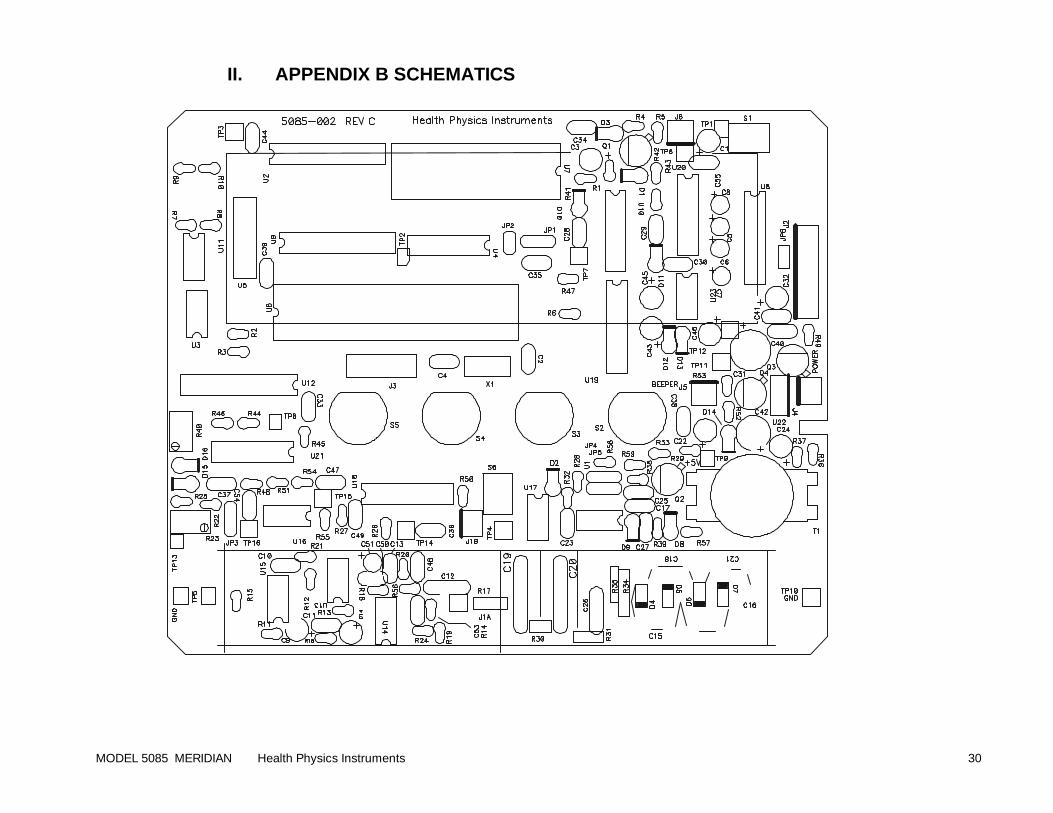
MODEL 5085 MERIDIAN Health Physics Instruments 30
II. APPENDIX B SCHEMATICS
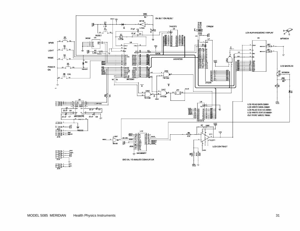
MODEL 5085 MERIDIAN Health Physics Instruments 31
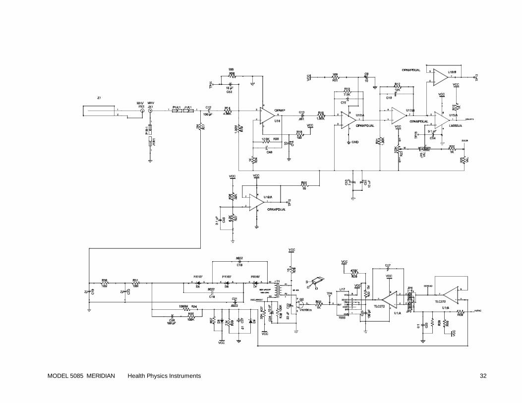
MODEL 5085 MERIDIAN Health Physics Instruments 32
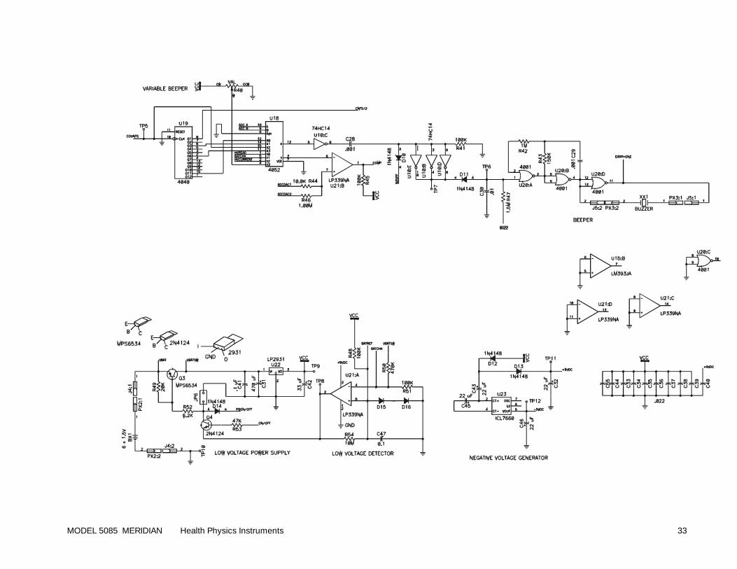
MODEL 5085 MERIDIAN Health Physics Instruments 33
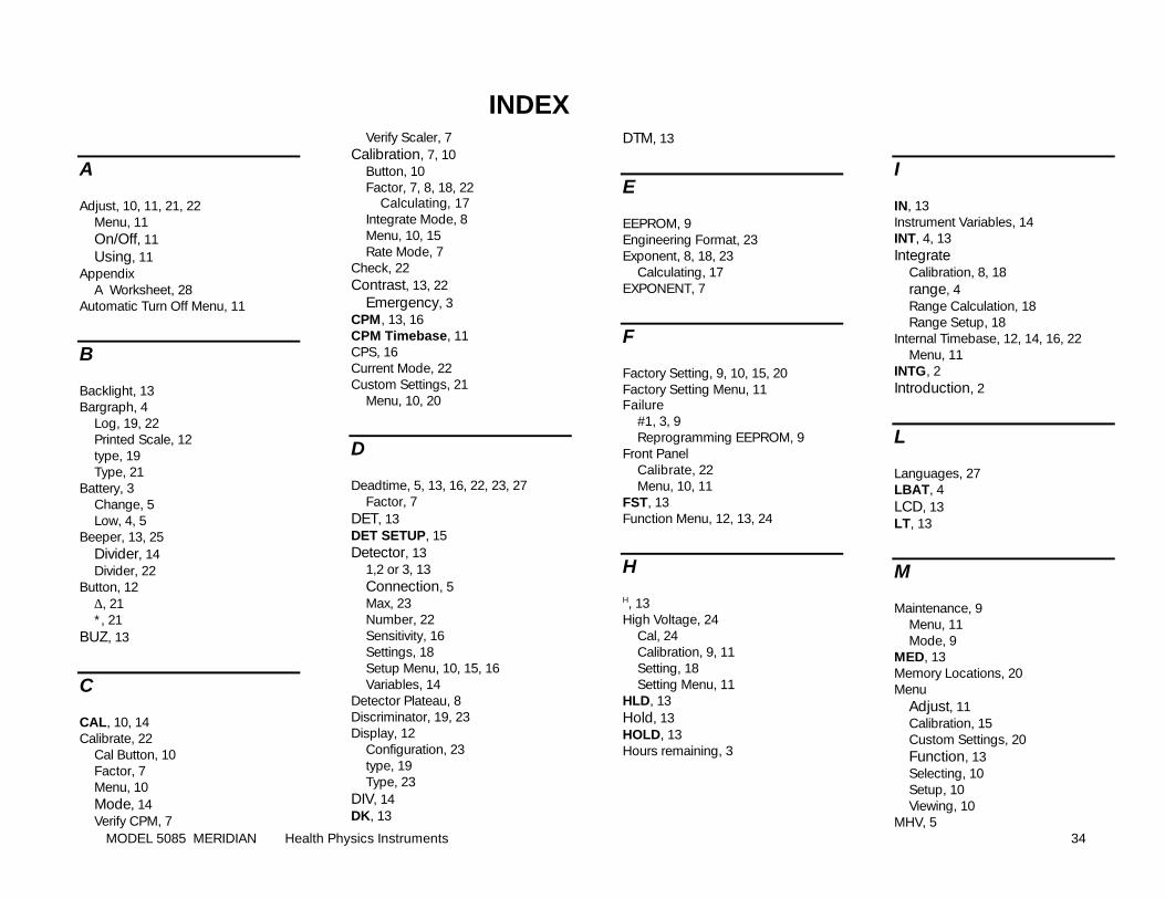
MODEL 5085 MERIDIAN Health Physics Instruments 34
INDEX
A
Adjust, 10, 11, 21, 22 Menu, 11 On/Off, 11 Using, 11
Appendix A Worksheet, 28
Automatic Turn Off Menu, 11
B
Backlight, 13 Bargraph, 4
Log, 19, 22 Printed Scale, 12 type, 19 Type, 21
Battery, 3 Change, 5 Low, 4, 5
Beeper, 13, 25 Divider, 14 Divider, 22
Button, 12 ∆, 21 *, 21
BUZ, 13
C
CAL, 10, 14 Calibrate, 22
Cal Button, 10 Factor, 7 Menu, 10 Mode, 14 Verify CPM, 7
Verify Scaler, 7 Calibration, 7, 10
Button, 10 Factor, 7, 8, 18, 22
Calculating, 17 Integrate Mode, 8 Menu, 10, 15 Rate Mode, 7
Check, 22 Contrast, 13, 22
Emergency, 3 CPM, 13, 16 CPM Timebase, 11 CPS, 16 Current Mode, 22 Custom Settings, 21
Menu, 10, 20
D
Deadtime, 5, 13, 16, 22, 23, 27 Factor, 7
DET, 13 DET SETUP, 15 Detector, 13
1,2 or 3, 13 Connection, 5 Max, 23 Number, 22 Sensitivity, 16 Settings, 18 Setup Menu, 10, 15, 16 Variables, 14
Detector Plateau, 8 Discriminator, 19, 23 Display, 12
Configuration, 23 type, 19 Type, 23
DIV, 14 DK, 13
DTM, 13
E
EEPROM, 9 Engineering Format, 23 Exponent, 8, 18, 23
Calculating, 17 EXPONENT, 7
F
Factory Setting, 9, 10, 15, 20 Factory Setting Menu, 11 Failure
#1, 3, 9 Reprogramming EEPROM, 9
Front Panel Calibrate, 22 Menu, 10, 11
FST, 13 Function Menu, 12, 13, 24
H
H, 13 High Voltage, 24
Cal, 24 Calibration, 9, 11 Setting, 18 Setting Menu, 11
HLD, 13 Hold, 13 HOLD, 13 Hours remaining, 3
I
IN, 13 Instrument Variables, 14 INT, 4, 13 Integrate
Calibration, 8, 18 range, 4 Range Calculation, 18 Range Setup, 18
Internal Timebase, 12, 14, 16, 22 Menu, 11
INTG, 2 Introduction, 2
L
Languages, 27 LBAT, 4 LCD, 13 LT, 13
M
Maintenance, 9 Menu, 11 Mode, 9
MED, 13 Memory Locations, 20 Menu
Adjust, 11 Calibration, 15 Custom Settings, 20 Function, 13 Selecting, 10 Setup, 10 Viewing, 10
MHV, 5
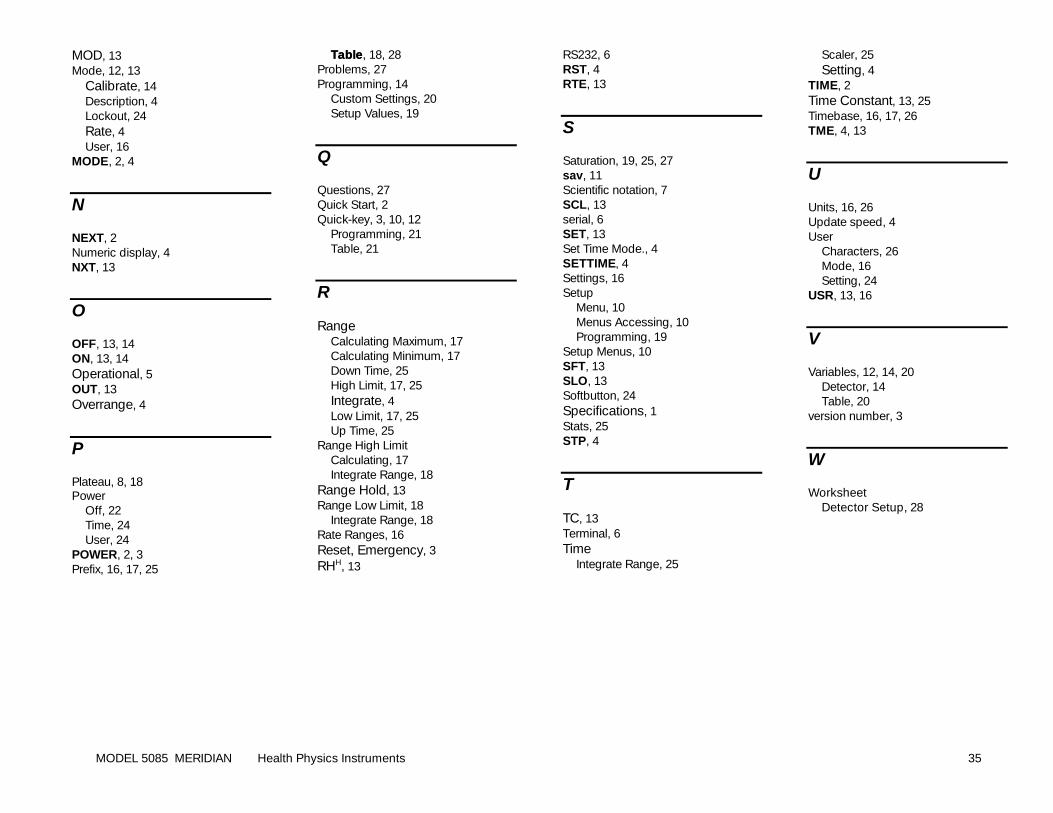
MODEL 5085 MERIDIAN Health Physics Instruments 35
MOD, 13 Mode, 12, 13
Calibrate, 14 Description, 4 Lockout, 24 Rate, 4 User, 16
MODE, 2, 4
N
NEXT, 2 Numeric display, 4 NXT, 13
O
OFF, 13, 14 ON, 13, 14 Operational, 5 OUT, 13 Overrange, 4
P
Plateau, 8, 18 Power
Off, 22 Time, 24 User, 24
POWER, 2, 3 Prefix, 16, 17, 25
TableTable, 18, 28 Problems, 27 Programming, 14
Custom Settings, 20 Setup Values, 19
Q
Questions, 27 Quick Start, 2 Quick-key, 3, 10, 12
Programming, 21 Table, 21
R
Range Calculating Maximum, 17 Calculating Minimum, 17 Down Time, 25 High Limit, 17, 25 Integrate, 4 Low Limit, 17, 25 Up Time, 25
Range High Limit Calculating, 17 Integrate Range, 18
Range Hold, 13 Range Low Limit, 18
Integrate Range, 18 Rate Ranges, 16 Reset, Emergency, 3 RHH, 13
RS232, 6 RST, 4 RTE, 13
S
Saturation, 19, 25, 27 sav, 11 Scientific notation, 7 SCL, 13 serial, 6 SET, 13 Set Time Mode., 4 SETTIME, 4 Settings, 16 Setup
Menu, 10 Menus Accessing, 10 Programming, 19
Setup Menus, 10 SFT, 13 SLO, 13 Softbutton, 24 Specifications, 1 Stats, 25 STP, 4
T
TC, 13 Terminal, 6 Time
Integrate Range, 25
Scaler, 25 Setting, 4
TIME, 2 Time Constant, 13, 25 Timebase, 16, 17, 26 TME, 4, 13
U
Units, 16, 26 Update speed, 4 User
Characters, 26 Mode, 16 Setting, 24
USR, 13, 16
V
Variables, 12, 14, 20 Detector, 14 Table, 20
version number, 3
W
Worksheet Detector Setup, 28


![Dual Purpose FWT Domain Spread Spectrum Image Watermarking ...malay/Papers/IJCEE_final[1].pdf · Dual Purpose FWT Domain Spread Spectrum Image Watermarking in Real ... digital watermarking](https://static.fdocuments.us/doc/165x107/5af327dc7f8b9ad06191abab/dual-purpose-fwt-domain-spread-spectrum-image-watermarking-malaypapersijceefinal1pdfdual.jpg)