MANITOU AMERICAS, INC. - Equipment · PDF fileMANITOU AMERICAS, INC. One Gehl Way P. O. Box...
173
MANITOU AMERICAS, INC. One Gehl Way P. O. Box 179 West Bend, WI 53095-0179 U.S.A Website: www.us.manitou.com For parts orders contact your Manitou dealer or call: Manitou Americas Parts Department. 262-334-6653 Fax (254) 867--6504 MLT625-75 H S1-E3 Operator Manual Catalog No. 51900001 In. Rel. 03-2011 THIS OPERATOR’S MANUAL MUST BE KEPT IN THE LIFT TRUCK AND MUST BE READ AND UNDERSTOOD BY OPERATORS.
Transcript of MANITOU AMERICAS, INC. - Equipment · PDF fileMANITOU AMERICAS, INC. One Gehl Way P. O. Box...

MANITOU AMERICAS, INC.One Gehl WayP. O. Box 179
West Bend, WI 53095-0179 U.S.A
Website: www.us.manitou.com
For parts orders contact your Manitou dealer or call:Manitou Americas Parts Department. 262-334-6653
Fax (254) 867--6504
MLT625-75 H S1-E3
Operator ManualCatalog No. 51900001
In. Rel. 03-2011
THIS OPERATOR’S MANUAL MUST BE KEPT IN THE LIFT TRUCK AND MUST BE READ AND UNDERSTOOD
BY OPERATORS.


0 - ROUGH TERRAIN FORKLIFT TRUCK GENERAL SAFETY STANDARDS
1 - OPERATING & SAFETY INSTRUCTION
2 - DESCRIPTION
3 - MAINTENANCE
4 - ATTACHMENTS
5 - ELECTRICAL & HYDRAULIC SCHEMATIC
THE TEXTS AND ILLUSTRATIONS IN THIS DOCUMENT MUST NOT BE REPRODUCED EITHER WHOLLY OR IN PART.
RELEASE: 03/11 Initial Release

1-2


ROUGH TERRAIN FORKLIFT TRUCKGENERAL SAFETY STANDARDS
I

1-2

ROUGH TERRAIN FORKLIFT TRUCK GENERAL SAFETY STANDARDS
STUDY THE OPERATOR/SERVICE MANUALSThe information in this manual provides general instructions for the safe operation and maintenance of your
forklift truck. This information is vital and must be clearly understood by the operator and serviceman. Study
this manual and the Rough Terrain Forklift Safety Manual (part no. 422494) thoroughly and carefully before
operating or servicing your forklift. Contact your dealer or Manitou North America, Inc. if you have any ques-
tions concerning your forklift, its operation, service or parts. Keep both manuals in the literature box on the
forklift available for reference. If either manual becomes illegible or is missing, contact your dealer for replace-
ments immediately. This manual cannot cover every situation that might result in an accident. It is the respon-
sibility of the operator to always remain alert for potential hazards and be prepared to avoid them!
ADDITIONAL RECOMMENDED LITERATURE:ANSI / ITSDF B56.6 is the national consensus standard for rough terrain forklift trucks. It contains rules about
forklift safety, maintenance, safe operation, training, and supervision. Forklift owners should learn this stan-
dard and make it available for their operators, service personnel, and supervisors. These standards can be
obtained, free of charge, from the Industrial Truck Standards Development Foundation (ITSDF) on their web-
site at www.itsdf.org. The following references are examples from the standard, addressing forklift operators:
A.) OPERATOR TRAINING QUALIFICATIONS1.) The user shall ensure that operators understand that safe operation is the operator’s responsibility. The
user shall ensure that operators are knowledgeable of, and observe, all safety rules and practices.
2.) Create an effective operator training program centered around user company’s policies, operating condi-
tions, and rough terrain forklift trucks. The program should be presented completely to all new operators and
not be condensed for those claiming previous experience.
3.) Information on operator training is available from several sources, including rough terrain forklift truck man-
ufacturers, users, government agencies, etc.
4.) An operator training program should consist of the following:
a.) careful selection of the operator, considering physical qualifications, job attitude, and aptitude;
b.) emphasis on safety of stock, equipment, operator, and other personnel;
c.) citing of rules and why they were formulated;
d.) basic fundamentals of rough terrain forklift truck and component design as related to safety, e.g.,
in.-lb (N-m) loading, mechanical limitations, center of gravity, stability, etc.;
e.) introduction to equipment, control locations, and functions. Explain how they work when used
properly and problems when used improperly.
f.) supervise practice on operating course remote from normal activity and designed to simulate
actual operations, e.g., lumber stacking, elevating shingles to the roof, etc.;
g.) oral, written, and operational performance tests and evaluations during and at completion of the
course;
h.) refresher courses, which may be condensed versions of the primary
course, and periodic “on job” operator evaluation;
i.) understanding of nameplate data and operator instructions and warning information appearing on
the rough terrain forklift truck.
B.) GENERAL SAFETY PRACTICES1.) Rough terrain forklift trucks can cause injury if improperly used or maintained.
2.) Only authorized operators trained to adhere strictly to all operating instructions shall be permitted to oper-
ate rough terrain forklift trucks. Unusual operating conditions may require additional safety precautions, train-
ing, and special operating instructions.
3.) Modifications and additions which affect capacity or safe operation shall not be preformed without the man-
ufacturer’s prior written approval. Where such authorization is granted, capacity, operation, and maintenance
instruction plates, tags, or decals shall be changed accordingly.
4.) If the rough terrain forklift truck is equipped with front end attachment(s) or optional forks, the user shall see
that the truck is marked to identify the forks or attachment(s), show the approximate weight of the truck and
fork or attachment combination, and show the capacity of the truck with forks or attachment(s) at maximum
elevation with load laterally centered.
5.) The user shall see that all nameplates and caution and instruction markings are in place and legible.
6.) The user shall consider that changes in load dimension may affect rough terrain forklift truck capacity.
II
ROUGH TERRAIN FORKLIFT TRUCK GENERAL SAFETY STANDARDS (cont.)
B.) GENERAL SAFETY PRACTICES (cont.)7.) Where steering can be accomplished with either hand and the steering mechanism is of a type that pre-vents road reactions from causing the handwheel to spin (power steering or equivalent), steering knobs maybe used. When used, steering knobs shall be of a type that can be engaged by the operator’s hand from thetop and shall be within the periphery of the steering handwheel.8.) Experience has shown that rough terrain forklift trucks which comply with stability requirements are stablewhen properly operated. However, improper operation, faulty maintenance, or poor housekeeping may con-tribute to a condition of instability and defeat the purpose of the requirements.9.) Users shall give consideration to special operating conditions. The amount of forward and rearward tilt tobe used is governed by the application. Although the use of maximum rearward tilt is allowable under certainconditions, such as traveling with the load lowered, the stability of a rough terrain forklift truck as determinedby standardized tests does not encompass consideration for excessive tilt at high elevations or the operationof trucks with excessive off-center loads.10.) Some of the conditions which may affect stability are ground and floor conditions, grade, speed, loading(rough terrain forklift trucks equipped with attachments behave as partially loaded trucks even when operatedwithout a load on the attachment), dynamic and static forces, improper tire inflation, and the judgement exer-cised by the operator.
C.) OPERATING SAFETY RULES AND PRACTICES1.) Safe operation is the responsibility of the operator.2.) This equipment can be dangerous if not used properly. The operator shall develop safe working habits andalso be aware of hazardous conditions in order to protect himself, other personnel, the rough terrain forklifttruck, and other material.3.) The operator shall be familiar with the operation and function of all controls and instruments before under-taking to operate the rough terrain forklift truck.4.) Before operating any rough terrain forklift truck, truck operators shall have read and be familiar with theoperator’s manual for the particular truck being operated.5.) Before starting to operate the rough terrain forklift truck:
a.) be in operating position and fasten seat belt;b.) place directional controls in neutral;c.) apply brakes;d.) start engine.
6.) Do not start or operate the rough terrain forklift truck, any of its functions, or attachments from any placeother than the designated operator’s position.7.) Keep hands and feet inside the operator’s designated area or compartment. Do not put any part of thebody outside the operator compartment of the rough terrain forklift truck.8.) Never put any part of the body into the mast structure or between the mast and the rough terrain forklifttruck.9.) Never put any part of the body within the reach mechanism of the rough terrain forklift truck or other attach-ments.10.) Understand rough terrain forklift limitations and operate the truck in a safe manner so as not to cause injuryto personnel.11.) Do not allow anyone to stand or pass under the elevated portion of any rough terrain forklift truck, whetherempty or loaded.12.) Do not permit passengers to ride on rough terrain forklift trucks.13.) Check clearance carefully before driving under electrical lines, bridges, etc.14.) A rough terrain forklift truck is attended when the operator is less than 25 ft (7.6m) from the truck, whichremains in his view.15.) A rough terrain forklift truck is unattended when the operator is 25ft (7.6m) or more from the truck, whichremains in his view, or whenever the operator leaves the truck and it is not in his view.16.) Before leaving the operator’s position:
a.) bring rough terrain forklift truck to a complete stop;b.) place directional controls in neutral;c.) apply the parking brake;d.) lower load-engaging means fully, unless supporting an occupied elevated platform;e.) stop the engine;f.) if the rough terrain forklift truck must be left on an incline, block the wheels;g.) fully lower the load-engaging means.
17.) Maintain a safe distance from the edge of ramps, platforms, and other similar working surfaces.18.) Do no move railroad cars or trailer with a rough terrain forklift truck.
III
ROUGH TERRAIN FORKLIFT TRUCK GENERAL SAFETY STANDARDS (cont.)
C.) OPERATING SAFETY RULES AND PRACTICES (cont.)19.) Do not use a rough terrain forklift truck for opening or closing railroad car doors.20.) In areas classified as hazardous, use only rough terrain forklift trucks approved for use in those areas.21.) Report all accidents involving personnel, building structures, and equipment to the supervisor or asdirected.22.) Do not add to, or modify, the rough terrain forklift truck.23.) Do not block access to fire aisles, stairways, and fire equipment.24.) For rough terrain forklift trucks equipped with a differential lock, the lock should not be engaged when driv-ing on the road or at high speeds or when turning. If the lock is engaged when turning, there could be loss ofsteering control.25.) Observe all traffic regulations including authorized speed limits. Under normal traffic conditions, keep tothe right, maintain a safe distance, based on speed of travel, from the truck ahead; and keep the truck undercontrol at all times.26.) Yield the right-of-way to pedestrians and emergency vehicles such as ambulances and fire trucks.27.) Do not pass another truck traveling in the same direction at intersections, blind spots, or at other danger-ous locations.28.) Slow down and sound the audible warning device(s) at cross-aisles and other locations where vision isobstructed.29.) Cross railroad tracks at an angle wherever possible. Do not park closer than 6 ft (1.8m) to the nearest railof a railroad track.30.) Keep a clear view of the path of travel and observe other traffic, personnel, and safe clearances.31.) If the load being carried obstructs forward view, travel with the load trailing.32.) Ascend or descend grades slowly and with caution.
a.) When ascending or descending grades in excess of 5%, loaded rough terrain forklift trucks should be driven with the load upgrade.b.) Unloaded rough terrain forklift trucks should be operated on all grades with the load-engaging means downgrade.c.) On all grades, the load and load-engaging means shall be tilted back, if applicable, and raised only as far as necessary to clear the road surface.d.) Avoid turning, if possible, and use extreme caution on grades, ramps, or inclines; normallytravel straight up or down.
33.) Under all travel conditions, operate the rough terrain forklift truck at a speed that will permit it to be broughtto a stop in a safe manner.34.) Travel with load-engaging means or load low and, where possible, tilted back. Do not elevate the loadexcept during stacking.35.) Make starts, stops, turns, or direction reversals in a smooth manner so as not to shift load and/or overturnthe rough terrain forklift truck.36.) Do not indulge in stunt driving or horseplay.37.) Slow down for wet and slippery surfaces.38.) Before driving over a dockboard or bridge plate, be sure that it is properly secured. Drive carefully andslowly across the dockboard or bridge plate, and never exceed its rated capacity.39.) Do not drive rough terrain forklift trucks onto any elevator unless specifically authorized to do so.Approach elevators slowly, and then enter squarely after the elevator car is properly leveled. Once on the ele-vator, neutralize the controls, shut off engine, and set brakes. It is advisable that all other personnel leave theelevator before truck is allowed to enter or leave.40.) Avoid running over loose objects on the roadway surface.41.) When negotiating turns, reduce speed to a safe level, and turn steering handwheel in a smooth sweepingmotion. Except when maneuvering at a very low speed, turn the steering handwheel at a moderate, even rate.42.) Use special care when traveling without load, as the risk of lateral overturning is greater.43.) Improper use of stabilizer controls (if so equipped) could cause rough terrain forklift truck upset. Alwayslower the carriage before operating stabilizer controls.44.) For rough terrain forklift trucks equipped with lateral leveling:
a.) Always level the frame before raising the boom or mast, with or without a load.b.) Lateral leveling should not be used to position an elevated load; instead, lower the load andreposition the rough terrain forklift truck.
45.) Handle only stable or safely arranged loads.a.) When handling off-center loads which cannot be centered, operate with extra caution.b.) Handle only loads within the capacity of the rough terrain forklift truck.c.) Handle loads exceeding the dimensions used to establish rough terrain forklift truck capacity with extra caution. Stability and maneuverability may be adversely affected.
IV
ROUGH TERRAIN FORKLIFT TRUCK GENERAL SAFETY STANDARDS (cont.)
C.) OPERATING SAFETY RULES AND PRACTICES (cont.)46.) When attachments are used, extra care shall be taken in securing, manipulating, positioning, and trans-
porting the load. Operate rough terrain forklift trucks equipped with attachments as partially loaded trucks
when not handling a load.
47.) Completely engage the load with the load-engaging means. Fork length should be at least two-thirds of
load length. Where tilt is provided, carefully tilt the load backward to stabilize the load. Caution should be used
in tilting backward with high or segmented loads.
48.) Use extreme care when tilting load forward or backward, particularly when high tiering. Do not tilt forward
with load-engaging means elevated except to pick up or deposit a load over a rack or stack. When stacking
or tiering, use only enough backward tilt to stabilize the load.
49.) The handling of suspended loads by means of a crane arm (boom) or other device can introduce dynam-
ic forces affecting the stability of a rough terrain forklift truck. Grades and sudden starts, stops, and turns can
cause the load to swing and create a hazard if not externally stabilized. When handling suspended loads:
a.) do not exceed the truck manufacturer’s capacity of the rough terrain forklift truck as equipped
for handling suspended loads.
b.) only lift the load vertically and never drag it horizontally;
c.) transport the load with the bottom of the load and the mast as low as possible;
d.) with load elevated, maneuver the rough terrain forklift truck slowly and cautiously, and only to
the extent necessary to permit lowering to the transport position;
e.) use tag lines to restrain load swing whenever possible.
50.) At the beginning of each shift and before operating the rough terrain forklift truck, check its condition,
giving special attention to:
a.) tires and their inflation pressure
b.) warning devices
c.) lights
d.) lift and tilt systems, load-engaging means, chains, cables, and limit switches
e.) brakes
f.) steering mechanism
g.) fuel system(s)
51.) If the rough terrain forklift truck is found to be in need of repair or in any way unsafe, or if it contributes to
an unsafe condition, the matter shall be reported immediately to the user’s designated authority, and the truck
shall not be operated until it has been restored to safe operating condition.
52.) If during operation the rough terrain forklift truck becomes unsafe in any way, the matter shall be reported
immediately to the user’s designated authority, and the truck shall not be operated until it has been restored to
safe operating condition.
53.) Do not make repairs or adjustments unless specifically authorized to do so.
54.) When refueling, smoking in the area shall not be permitted, the engine shall be stopped, and the opera-
tor shall not be on the rough terrain forklift
truck.
55.) Spillage of oil or fuel shall be carefully and completely absorbed or evaporated and fuel tank cap replaced
before restarting engine.
56.) Do not use open flames when checking electrolyte level in storage batteries, liquid level in fuel tanks, or
the condition of LPG fuel lines and connectors.
57.) Do not lift personnel with the forklift. If the forklift must be used to lift people, precautions for the protec-
tion of the personnel must be taken (see ITSDF B56.6, chapter 5.15 Elevating Personnel).
V

VI
ROUGH TERRAIN FORKLIFT TRUCK GENERAL SAFETY STANDARDS (cont.)
D.) SUSPENDED LOADS
A jib or truss boom should ONLY be used to lift and place loads when the machine is stationary and the frame
is level. Transporting suspended loads must ALWAYS be done slowly and cautiously, with the boom and load
as low as possible. Use taglines to restrict loads from swinging, to avoid overturn.
The handling of suspended loads by means of a truss boom or other similar device can introduce dynamic
forces affecting the stability of the machine that are not considered in the stability criteria of industry test
standards. Grades and sudden starts, stops and turns can cause the load to swing and create a hazard.
Guidelines for “Free Rigging / Suspended Loads”
1. DO NOT exceed the rated capacity of the telescopic handler as equipped for handling suspended
loads. The weight of the rigging must be included as part of the load.
2. During transport, DO NOT raise the load more than 12 inches (305 mm) above the ground, or raise
the boom more than 45 degrees.
3. Only lift the load vertically – NEVER drag it horizontally.
4. Use multiple pickup points on the load when possible. Use taglines to restrain the load from swinging
and rotating.
5. Start, travel, turn and stop SLOWLY to prevent the load from swinging. DO NOT exceed walking
speed.
6. Inspect rigging before use. Rigging must be in good condition and in the U.S. comply with OSHA
regulation §1910.184, “Slings,” or §1926.251, “Rigging equipment for material handling.”
7. Rigging equipment attached to the forks must be secured such that it cannot move either sideways or
fore and aft. The load center must not exceed 24 inches (610 mm).
8. DO NOT lift the load with anyone on the load, rigging or lift equipment, and NEVER lift the load over
personnel.
9. Beware of the wind, which can cause suspended loads to swing, even with taglines.
10. DO NOT attempt to use frame-leveling to compensate for load swing.
U.S. OSHA regulations effective November 8, 2010 (29 CFR Part 1926, Subpart CC - Cranes and Derricks inConstruction) include requirements for employers that use powered industrial trucks ("forklifts") configuredto hoist (by means of a winch or hook) and move suspended loads horizontally. In particular, this regulationapplies to any rough-terrain forklift (e.g., "telescopic handler") equipped with a jib or truss boom with ahook (with or without a winch), or a hook assembly attached to the forks. [Note: This regulation is inaddition to the OSHA regulation that requires specific forklift operator training: §1910.178(l).]
When a forklift / telescopic handler is configured and used for hoisting, the employer must ensure that:
1. Forklift, lift equipment and rigging have been inspected (each shift, month and year) and are in good, safe condition and properly installed.
2. An operator's manual and applicable load charts are on the forklift.
3. Work zone ground conditions can support the equipment and load. Any hazardous conditions in the work area have been identified, and the operator notified.
4. Equipment is being used within its rated capacity and in accordance with the manufacturer'sinstructions.
WARNING

VII
5. Operator and crew members have been trained in the safe use and operation of the equipment, including how to avoid electrocution.
6. During use, no part of the equipment, load line or load will be within the minimum clearance distance specified by OSHA [10 feet (3.0 m), and more for lines rated over 50 kV] of any energized power line, and any taglines used are non-conductive.
7. In addition, for lift equipment with a rated capacity greater than 2000 lbs. (907 kg), the employer must ensure that:
a.) An accessible fire extinguisher is on the forklift;
b.) Monthly and annual inspections are performed and documented, and records retained (three months for monthly, one year for annual);
c.) Before November 10, 2014, operators must have had the additional training and qualification / certification required by OSHA regulations §1926.1427 and §1926.1430.
Note: Refer to the full text of the OSHA crane regulation (29 CFR Part 1926, Subpart CC) for a detailed description

ROUGH TERRAIN FORKLIFT TRUCK GENERAL SAFETY STANDARDS (cont.)
CONCLUSION:
1.) ATTEND OPERATOR TRAINING CLASSESThe forklift operator must clearly understand all instructions concerning the safe operation of the forklift and all
safety rules and regulations of the work site. They must have successfully completed a training coarse in
accordance with the Powered Industrial Truck Standard (29 CFR 1910.178) as described by the Occupational
Safety and Health Administration (OSHA). They must be qualified as to their visual, hearing, physical, and
mental ability to operate the equipment safely. NEVER use drugs or alcohol while operating a forklift! NEVER
operate or allow anyone to operate a forklift when mental alertness or coordination is impaired! An operator
on prescription or over-the-counter drugs must consult a medical professional regarding any side effects of the
medication that may impair their ability to safely operate the forklift.
2.) CREATE A MAINTENANCE PROGRAMOSHA recommends a maintenance log, listing repairs requested and completed, for each forklift. Also, “lock
out tag procedures” should be utilized. If the forklift malfunctions; park it safely, remove the key, tag “Do Not
Use”, and report the problem to the proper authority or authorized service personnel immediately.
ROUGH TERRAIN FORKLIFT TRUCK GENERAL SAFETY STANDARDS (cont.)
2.) CREATE A MAINTENANCE PROGRAM (cont.)For the best forklift performance and operation, a maintenance program is required. Use the hour meter on
the instrument panel to keep maintenance properly scheduled (see SECTION TWO - “Servicing Schedule”).
For repairs on major components (engine, transmission, etc.), contact your nearest dealer for a Repair Manual.
Do not operate a forklift that is damaged or does not function properly. Only authorized personnel may make
repairs or adjustments to the lift truck. After repairs, the lift truck must be tested for safe operation before
returning to service.
3.) FORKLIFT KNOWLEDGEForklift trucks can cause serious injury if improperly used or maintained. Study all of the manuals provided for
your forklift model. Learn the locations and meanings of all safety decals. If any decals are illegible or miss-
ing, have them replaced immediately. Make sure all safety features provided by the original manufacturer are
in place and function properly. Do not operate a forklift with damaged, missing or unsafe components. Have
it repaired by authorized service personnel. Learn the functions of all controls, gauges, indicator lights, etc. on
the forklift. Know the speed/gear ranges, braking and steering capabilities, load ratings and clearances. When
referring to the location of forklift components, the terms “left”, “right”, “front”, and “rear” are related to the oper-
ator seated normally, facing forward in the operator’s seat. If you have any questions about the forklift, con-
sult your supervisor. Failure to fully understand or obey safety warnings can result in serious injury or death!
4.) WORK SITE KNOWLEDGEBefore operating on a work site, learn the rules for movement of people, forklifts and all other traffic. Check
the size, weight, and condition of the loads you will be expected to handle. Verify that they are properly
secured and safe to transport. Learn where the loads are to be placed, planning your route for a safe
approach, watching for hazardous conditions. Will a signal man be required to help place the load? Remove
any debris which may cause tire damage or rupture. Plan your route around problem areas or have them cor-
rected. Inform the supervisor of any unsafe conditions observed at the site. Examples of hazards: power
lines, cables, low clearance structures, garage doors, telephone pole guide lines, fencing, loose lumber, build-
ing materials, drop-offs, trenches, rough/soft spots, oil spills, deep mud, steep inclines, railroad tracks, curbs,
etc.. NEVER approach power lines, gas lines or other utilities with the forklift! Always verify that local,
state/provincial and federal regulations have been met. Report any accidents involving personnel, building
structures, and equipment to the supervisor immediately. Always remain alert - conditions are constantly
changing at the work site!
TECHNICAL SUPPORTAll data provided in this manual is subject to production changes, addition of new models, and improved prod-
uct designs. If a question arises regarding your forklift, please consult your dealer or Manitou NA, Inc. for the
latest information. When ordering service parts or requesting technical information, be prepared to quote the
applicable Model/Serial Numbers.
VIII
IX
SAFETY MESSAGES
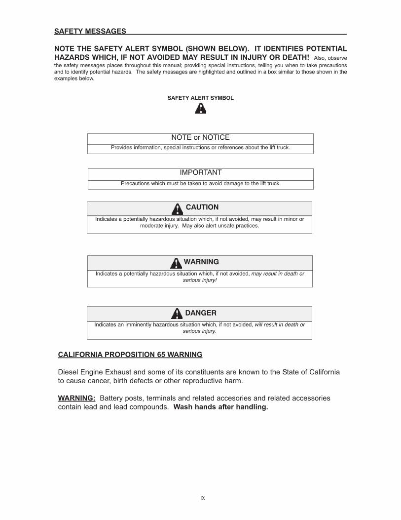
NOTE THE SAFETY ALERT SYMBOL (SHOWN BELOW). IT IDENTIFIES POTENTIALHAZARDS WHICH, IF NOT AVOIDED MAY RESULT IN INJURY OR DEATH! Also, observethe safety messages places throughout this manual; providing special instructions, telling you when to take precautionsand to identify potential hazards. The safety messages are highlighted and outlined in a box similar to those shown in theexamples below.
SAFETY ALERT SYMBOL
Indicates an imminently hazardous situation which, if not avoided, will result in death orserious injury.
Indicates a potentially hazardous situation which, if not avoided, may result in death orserious injury!
Indicates a potentially hazardous situation which, if not avoided, may result in minor ormoderate injury. May also alert unsafe practices.
Provides information, special instructions or references about the lift truck.
NOTE or NOTICE
Precautions which must be taken to avoid damage to the lift truck.
IMPORTANT
CAUTION
WARNING
DANGER
CALIFORNIA PROPOSITION 65 WARNING
Diesel Engine Exhaust and some of its constituents are known to the State of California
to cause cancer, birth defects or other reproductive harm.
WARNING: Battery posts, terminals and related accesories and related accessories
contain lead and lead compounds. Wash hands after handling.

SAFETY DECALS
The purpose of this chapter is to introduce you to the safety messages, decals, and nameplates found onyour forklift truck. The decals are identified by name, part number, location, and a brief description. (Theforklift model logos, and other misc. decals not shown, can be found in your forklift parts manual.) Thedecals illustrated may not be exactly the same as those installed on your forklift; installation of the decalsvaries depending on the forklift model, series, decal updates, etc.. The size and location of some decalslimit the amount of information that can be placed upon it. For this reason, additional detailed informationnot found on the decals is provided through-out this manual.
Every decal placed on the lift truck is important; they are constant reminders of safety and instructions thatshould never be taken for granted. Even experienced operators can be seriously injured or killed by ignor-ing, refusing to enforce, or forgetting to follow safe operating procedures! Do not assume you know all safe-ty issues concerning the decals. Before operating the lift truck; learn the meaning(s) of the decals asdescribed in this manual. If any decal becomes illegible or missing, have it replaced immediately! Alwaysreplace decals using the same decal part no., unless otherwise specified by the manufacturer. For replace-ment decals not found in your parts manual, contact your nearest dealer. If you have any questions, contactyour supervisor or nearest dealer for advice before operating your forklift!
Before Starting - 801011(Boom equipped models). Location: on the brake fluid cover panel (tothe left and below the dash panel).
Safety Instructions - 420792(Mast equipped models). Location: on or near the operator manualstorage case, and/or on the dash panel.
Instructions for the forklift operator; before operating the forklift.
Use of Seat Belt - 801012(Boom equipped models). Location: to the right of theoperator, near the hydraulic control lever.
Instructs the operator to always wear the seat belt duringoperations, and never jump from an over-turning forklift.
X
801011

SAFETY DECALS
Emergency and Parking Brake - 801010Location: near the park brake lever.
Identifies the Emergency/Parking Brake Lever.
Alarm Must Sound - 496162Location: on the dash, in direct view of the operator.
The backup alarm must sound when the forklift is placed in reverse gear.
No Riders - 420732Location: on the cab entrance(s), and on or near wheel fenders and enginecover.
Informs: riders are not allowed on the forklift.
Clear of Raised Boom - 801006(Boom equipped models). Location: on both sidesof the boom nose.
Keep away from unsupported boom.
Clear of Power Lines - 801007(Boom equipped models). Location: on both sidesof the boom nose.
Keep away from power lines.
XI

SAFETY DECALS
Use of Frame Leveling - 801013(Boom equipped models). Location: to the right ofthe operator near the hydraulic control lever.
Frame leveling notice; load must be lowered.
Attachment and Boom Safety - 801009(Boom equipped models). Location: on both sides of theboom nose.
Important reminders of attachment and boom safety.
Hydraulic Coupling - 234805Location: near the quick-disconnect adapters.
Stop the engine and release hydraulic pressure before changingattachments.
Rotating Fan and Belt(s) - 801008Location: on the radiator near the fan, and on any fan belt/pulley cover(s).
Keep hands and clothing away from rotating fan and belts.
XII
SAFETY DECALS
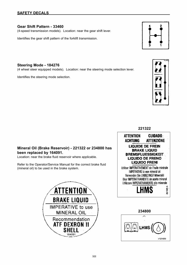
Gear Shift Pattern - 33460(4-speed transmission models). Location: near the gear shift lever.
Identifies the gear shift pattern of the forklift transmission.
Steering Mode - 184276(4 wheel steer equipped models). Location: near the steering mode selection lever.
Identifies the steering mode selection.
Mineral Oil (Brake Reservoir) - 221322 or 234800 has
been replaced by 164091.Location: near the brake fluid reservoir where applicable.
Refer to the Operator/Service Manual for the correct brake fluid
(mineral oil) to be used in the brake system.
XIII
221322
234800

SAFETY DECALS
Hydraulic Oil - 234798 or 76573Location: on the hydraulic tank or filler cap.
Identifies the hydraulic reservoir (tank) or filler cap.
Hydraulic Oil - 61024Location: on the hydraulic tank.
Identifies the hydraulic reservoir (tank).
Anti-Freeze - 234799Location: on the radiator, near the radiator filler cap.
Indicates required minimum to maximum anti-freeze protection (-220F to -400F).
Diesel Fuel - 161101Location: on the fuel tank, near the filler cap.
Identifies the fuel tank, and use of diesel fuel.
No Step - 496735Location: varies, depending on the forklift model.
Instructs personnel not to use the designated area as a step.
Do Not Tow - 494918(Hydrostatic equipped models). Location: on the
dash, in view of the operator.
Towing the forklift will damage the transmission;
refer to the operator’s manual.
XIV

SAFETY DECALS
Attachment Warning - 421016(Boom equipped models). Location: on the boom coupler,near where the retaining shaft is installed.
Reminder to operator; install attachment retaining shaft andsafety pin before operations.
Hook Here - 24653Location: at points provided on the forklift, where straps or chains may be attached tosecure the forklift to a trailer during transport.
Fork Safety - 426641(Mast equipped models). Location: on the front and back side of the mast’s outer rails,at eye level (4 required).
Instructs personnel not to travel beneath or upon the lift truck forks.
Pinch Point, Large, 2.5 x 4.5 in. - 426643Pinch Point, Small, 1.5 x 2.75 in. - 426642(Mast equipped models). Location: on the front and rear sidesof the mast cross bracing.
Keep fingers away from the mastcrossbracing.
HAND THROTTLE DANGER - 804784(Boom equipped models, option). Location: Near the hand throttle mechanism.
Reminder to operator; set parking brake before operating hand throttle.Disengage hand throttle before leaving the forklift.
XV
SAFETY DECALS
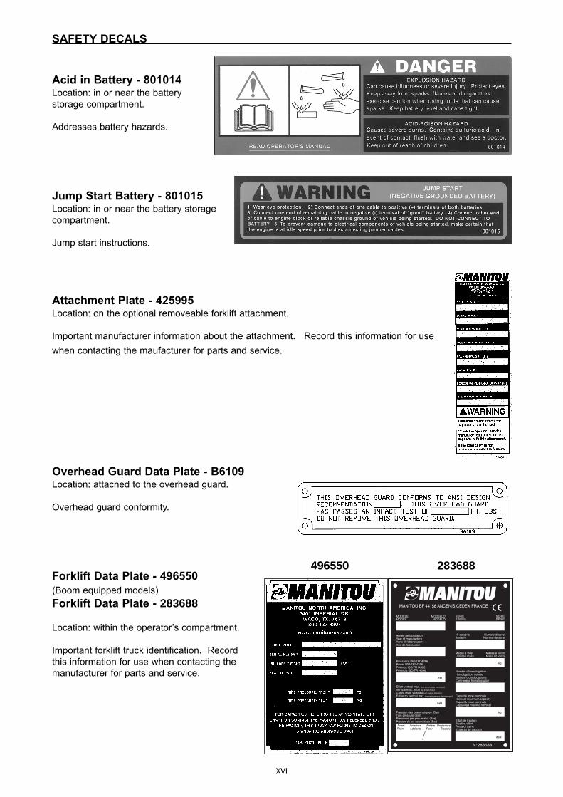
Acid in Battery - 801014Location: in or near the batterystorage compartment.
Addresses battery hazards.
Jump Start Battery - 801015Location: in or near the battery storagecompartment.
Jump start instructions.
Attachment Plate - 425995Location: on the optional removeable forklift attachment.
Important manufacturer information about the attachment. Record this information for usewhen contacting the maufacturer for parts and service.
Overhead Guard Data Plate - B6109Location: attached to the overhead guard.
Overhead guard conformity.
Forklift Data Plate - 496550(Boom equipped models)Forklift Data Plate - 283688 Location: within the operator’s compartment.
Important forklift truck identification. Recordthis information for use when contacting themanufacturer for parts and service.
XVI
496550 283688
MANITOU BF 44158 ANCENIS CEDEX FRANCE
N°283688
MODELEMODEL
MODELLOMODELO
SERIESERIES
SERIESERIE
N° de sérieSerial Nr
Numero di serieNúmero de serie
Masse à videUnladen mass
Numéro d'homologationHomologation numberNumero d'omologazioneContraseña homologacion
Capacité maxi nominaleNominal maximum capacityCapacità maxi nominaleCapacidad máximo nominal
Effort de tractionTractive effortForza di trainoEsfuerzo de traccion
Massa a vuotoMasa en vacio
Année de fabricationYear of manufactureAnno di fabbricazioneAño de fabricacion
Puissance ISO/TR14396Power ISO/TR14396Potenza ISO/TR14396Potencia ISO/TR14396
Effort vertical max. (sur accrochage remorque)
Vertical max. effort (on trailer hook)
Carico max. verticale (sul gancio di traino)
Esfuerzo vertical max. (sobre el gancho de remolque)
Pression des pneumatiques (Bar)Tyre pressure (Bar)Pressione per pneumatici (Bar)Presion de los neumáticos (Bar)
kW
daN
AvantFront
AnterioreAdelante
ArrièreRear
PosterioreTrasero
kg
kg
daN

1-2

1-1
1 - OPERATINGAND SAFETYINSTRUCTIONS

1-2
1-3
TABLE OF CONTENTS
INSTRUCTIONS TO THE COMPANY MANAGER
THE SITETHE OPERATORTHE LIFT TRUCK
A - THE LIFT TRUCK’S SUITABILITY FOR THE JOBB - ADAPTATION OF THE LIFT TRUCK TO STANDARD ENVIRONMENTAL CONDITIONSC - MODIFICATION OF THE LIFT TRUCKD - FRENCH ROAD TRAFFIC RULES (or see current legislation in other countries)
THE INSTRUCTIONSTHE MAINTENANCE
INSTRUCTIONS FOR THE OPERATOR
PREAMBULEGENERAL INSTRUCTIONS
A - OPERATOR’S MANUALB - AUTHORIZATION FOR USE IN FRANCE (or see current legislation in other countries)C - MAINTENANCED - MODIFICATION OF THE LIFT TRUCKE - LIFTING PEOPLE
OPERATING INSTRUCTIONS UNLADEN AND LADENA - BEFORE STARTING THE LIFT TRUCKB - DRIVER’S OPERATING INSTRUCTIONSC - ENVIRONMENTD - VISIBILITYE - STARTING THE LIFT TRUCKF - DRIVING THE LIFT TRUCKG - STOPPING THE LIFT TRUCKH - DRIVING THE LIFT TRUCK ON THE PUBLIC HIGHWAY (or see current legislation in other countries)
INSTRUCTIONS FOR HANDLING A LOADA - CHOICE OF ATTACHMENTSB - MASS OF LOAD AND CENTRE OF GRAVITYC - LONGITUDINAL STABILITY LIMITER AND WARNING DEVICED - TRANSVERSE ATTITUDE OF THE LIFT TRUCKE - TAKING UP A LOAD ON THE GROUNDF - TAKING UP AND LAYING A HIGH LOAD ON TYRESG - TAKING UP AND LAYING A HIGH LOAD ON STABILIZERSH - TAKING UP AND LAYING DOWN A SUSPENDED LOADI - TRAVELLING WITH A SUSPENDED LOAD
PLATFORM OPERATING INSTRUCTIONSA - AUTHORISATION FOR USEB - SUITABILITY OF THE PLATFORM FOR THE JOBC - PRECAUTIONS WHEN USING THE PLATFORMD - USING THE PLATFORME - ENVIRONMENTF - MAINTENANCE
INSTRUCTIONS FOR USING THE RADIO-CONTROL
MAINTENANCE INSTRUCTIONS OF THE LIFT TRUCK
GENERAL INSTRUCTIONSMAINTENANCELUBRICANT AND FUEL LEVELSHYDRAULICELECTRICITYWELDINGWASHING THE LIFT TRUCK
IF THE LIFT TRUCK IS NOT TO BE USED FOR A LONG TIME
INTRODUCTIONPREPARING THE LIFT TRUCKPROTECTING THE I.C. ENGINEPROTECTING THE LIFT TRUCKBRINGING THE LIFT TRUCK BACK INTO SERVICE
1 - 4
1 - 41 - 41 - 41 - 41 - 41 - 51 - 51 - 51 - 5
1 - 6
1 - 61 - 61 - 61 - 61 - 61 - 61 - 71 - 81 - 81 - 81 - 91 - 9
1 - 101 - 101 - 111 - 121 - 141 - 141 - 141 - 141 - 151 - 151 - 161 - 181 - 201 - 201 - 211 - 211 - 211 - 211 - 211 - 211 - 221 - 23
1 - 24
1 - 241 - 241 - 241 - 241 - 241 - 251 - 25
1 - 26
1 - 261 - 261 - 261 - 261 - 27
1-4
INSTRUCTIONS TO THE COMPANY MANAGER
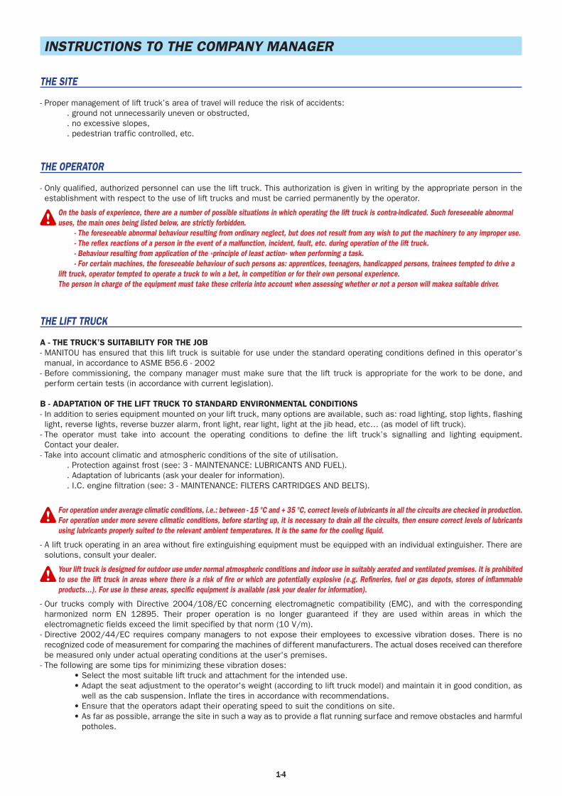
THE SITE
- Proper management of lift truck’s area of travel will reduce the risk of accidents:. ground not unnecessarily uneven or obstructed,. no excessive slopes,. pedestrian traffic controlled, etc.
THE OPERATOR
- Only qualified, authorized personnel can use the lift truck. This authorization is given in writing by the appropriate person in the establishment with respect to the use of lift trucks and must be carried permanently by the operator.
On the basis of experience, there are a number of possible situations in which operating the lift truck is contra-indicated. Such foreseeable abnormaluses, the main ones being listed below, are strictly forbidden. - The foreseeable abnormal behaviour resulting from ordinary neglect, but does not result from any wish to put the machinery to any improper use. - The reflex reactions of a person in the event of a malfunction, incident, fault, etc. during operation of the lift truck. - Behaviour resulting from application of the «principle of least action» when performing a task. - For certain machines, the foreseeable behaviour of such persons as: apprentices, teenagers, handicapped persons, trainees tempted to drive alift truck, operator tempted to operate a truck to win a bet, in competition or for their own personal experience.The person in charge of the equipment must take these criteria into account when assessing whether or not a person will makea suitable driver.
THE LIFT TRUCK
A - THE TRUCK’S SUITABILITY FOR THE JOB- MANITOU has ensured that this lift truck is suitable for use under the standard operating conditions defined in this operator’s manual, in accordance to ASME B56.6 - 2002
- Before commissioning, the company manager must make sure that the lift truck is appropriate for the work to be done, and perform certain tests (in accordance with current legislation).
B - ADAPTATION OF THE LIFT TRUCK TO STANDARD ENVIRONMENTAL CONDITIONS- In addition to series equipment mounted on your lift truck, many options are available, such as: road lighting, stop lights, flashing light, reverse lights, reverse buzzer alarm, front light, rear light, light at the jib head, etc… (as model of lift truck).
- The operator must take into account the operating conditions to define the lift truck’s signalling and lighting equipment. Contact your dealer.
- Take into account climatic and atmospheric conditions of the site of utilisation.. Protection against frost (see: 3 - MAINTENANCE: LUBRICANTS AND FUEL).. Adaptation of lubricants (ask your dealer for information).. I.C. engine filtration (see: 3 - MAINTENANCE: FILTERS CARTRIDGES AND BELTS).
For operation under average climatic conditions, i.e.: between - 15 °C and + 35 °C, correct levels of lubricants in all the circuits are checked in production.For operation under more severe climatic conditions, before starting up, it is necessary to drain all the circuits, then ensure correct levels of lubricantsusing lubricants properly suited to the relevant ambient temperatures. It is the same for the cooling liquid.
- A lift truck operating in an area without fire extinguishing equipment must be equipped with an individual extinguisher. There are solutions, consult your dealer.
Your lift truck is designed for outdoor use under normal atmospheric conditions and indoor use in suitably aerated and ventilated premises. It is prohibitedto use the lift truck in areas where there is a risk of fire or which are potentially explosive (e.g. Refineries, fuel or gas depots, stores of inflammableproducts…). For use in these areas, specific equipment is available (ask your dealer for information).
- Our trucks comply with Directive 2004/108/EC concerning electromagnetic compatibility (EMC), and with the corresponding harmonized norm EN 12895. Their proper operation is no longer guaranteed if they are used within areas in which the electromagnetic fields exceed the limit specified by that norm (10 V/m).
- Directive 2002/44/EC requires company managers to not expose their employees to excessive vibration doses. There is no recognized code of measurement for comparing the machines of different manufacturers. The actual doses received can therefore be measured only under actual operating conditions at the user's premises.
- The following are some tips for minimizing these vibration doses:• Select the most suitable lift truck and attachment for the intended use.• Adapt the seat adjustment to the operator's weight (according to lift truck model) and maintain it in good condition, as
well as the cab suspension. Inflate the tires in accordance with recommendations.• Ensure that the operators adapt their operating speed to suit the conditions on site.• As far as possible, arrange the site in such a way as to provide a flat running surface and remove obstacles and harmful
potholes.
1-5
C - MODIFICATION OF THE LIFT TRUCK- For your safety and that of others, you must not change the structure and settings of the various components used in your lift truck (hydraulic pressure, calibrating limiters, I.C. engine speed, addition of extra equipment, addition of counterweight, unapproved attachments, alarm systems, etc.) yourself. In this event, the manufacturer cannot be held responsible.
D - FRENCH ROAD TRAFFIC RULES(or see current legislation in other countries)
- Only one certificate of conformity is issued. It must be kept in a safe place.
THE INSTRUCTIONS
- The operator’s manual must always be in good condition and kept in the place provided on the lift truck and in the language used by the operator.
- The operator’s manual and any plates or stickers which are no longer legible or are damaged, must be replaced immediately.
THE MAINTENANCE
- Maintenance or repairs other than those detailed in part: 3 - MAINTENANCE must be carried out by qualified personnel (consult your dealer) and under the necessary safety conditions to maintain the health of the operator and any third party.
Your lift truck must be inspected periodically to ensure that it remains in compliance. The frequency of this inspection is defined by current legislation inthe country in which the lift truck is used.
1-6
INSTRUCTIONS FOR THE OPERATOR
PREAMBLE
WHENEVER YOU SEE THIS SYMBOL IT MEANS:
WARNING ! BE CAREFUL ! YOUR SAFETY OR THE SAFETY OF THE LIFT TRUCK IS AT RISK.
The risk of accident while using, servicing or repairing your lift truck can be restricted if you follow the safety instructions and safety measures detailedin these instruction.
- Only the operations and manœuvres described in these operator’s manual must be performed. The manufacturer cannot predict all possible risky situations. Consequently, the safety instructions given in the operator’s manual and on the lift truck itself are not exhaustive.
- At any time, as an operator, you must envisage, within reason, the possible risk to yourself, to others or to the lift truck itself when you use it.
Failure to respect the safety and operating instructions, or the instructions for repairing or servicing your lift truck may lead to serious, even fatalaccident.
GENERAL INSTRUCTIONS
A - OPERATOR’S MANUAL- Read the operator’s manual carefully.- The operator’s manual must always be in good condition and in the place provided for it on the lift truck.- You must report any plates and stickers which are no longer legible or which are damaged.
B - AUTHORISATION FOR USE IN FRANCE(or see current legislation in other countries)
- Only qualified, authorized personnel can use the lift truck. This authorization is given in writing by the appropriate person in the establishment with respect to the use of lift trucks and must be carried permanently by the operator.
- The operator is not competent to authorise the driving of the lift truck by another person.
C - MAINTENANCE- The operator must immediately advise his superior if his lift truck is not in good working order or does not comply with the safety notice.
- The operator is prohibited from carrying out any repairs or adjustments himself, unless he has been trained for this purpose. He must keep the lift truck properly cleaned if this is among his responsibilities.
- The operator must carry out daily maintenance (see: 3 - MAINTENANCE: A - DAILY OR EVERY 10 HOURS SERVICE).- The operator must ensure tyres are adapted to the nature of the ground (see area of the contact surface of the tyres in the chapter: 2 - DESCRIPTION: FRONT AND REAR TYRES). There are optional solutions, consult your dealer.
. SAND tyres.
. LAND tyres.
. Snow chains.
Do not use the lift truck if the tyres are incorrectly inflated, damaged or excessively worn, because this could put your own safety or that of others atrisk, or cause damage to the lift truck itself. The fitting of foam inflated tyres is prohibited and is not guaranteed by the manufacturer, excepting priorauthorisation.
D - MODIFICATION OF THE LIFT TRUCK- For your safety and that of others, you must not change the structure and settings of the various components used in your lift truck (hydraulic pressure, calibrating limiters, I.C. engine speed, addition of extra equipment, addition of counterweight, unapproved attachments, alarm systems, etc.) yourself. In this event, the manufacturer cannot be held responsible.

1-7
E - LIFTING PEOPLE- The use of working equipment and load lifting attachments to lift people is:
• either forbidden• or authorized exceptionally and under certain conditions (see current regulations
in the country in which the lift truck is used).- The pictogram posted at the operator station reminds you that:
• Left-hand column- It is forbidden to lift people, with any kind of attachment, using a non PLATFORM-fitted lift truck.
• Right-hand column- With a PLATFORM-fitted lift truck, people can only be lifted using platforms designed by MANITOU for the purpose.
- MANITOU sells equipment specifically designed for lifting people (OPTION PLATFORM lift truck, contact your dealer).

1-8
OPERATING INSTRUCTIONS UNLADEN AND LADEN
A - BEFORE STARTING THE LIFT TRUCK- Carry out daily maintenance (see: 3 - MAINTENANCE: A - DAILY OR EVERY 10 HOURS SERVICE).- Make sure the lights, indicators and windscreen wipers are working properly.- Make sure the rear view mirrors are in good condition, clean and properly adjusted.- Make sure the horn works.
B - DRIVER’S OPERATING INSTRUCTIONS- Whatever his experience, the operator is advised to familiarize himself with the position and operation of all the controls and instruments before operating the lift truck.
- Wear clothes suited for driving the lift truck, avoid loose clothes.- Make sure you have the appropriate protective equipment for the job to be done.- Prolonged exposure to high noise levels may cause hearing problems. It is recommended to wear ear muffs to protect against excessive noise.
- Always face the lift truck when getting into and leaving the driving seat and use the handle(s) provided for this purpose. Do not jump out of the seat to get down.
- Always pay attention when using the lift truck. Do not listen to the radio or music using headphones or earphones.- Never operate the lift truck when hands or feet are wet or soiled with greasy substances.- For increased comfort, adjust the seat to your requirements and adopt the correct position in the driver’s cab.
Under no circumstances must the seat be adjusted while the lift truck is moving.
- The operator must always be in his normal position in the driver’s cab. It is prohibited to have arms or legs, or generally any part of the body, protruding from the driver’s cab of the lift truck.
- The safety belt must be worn and adjusted to the operator’s size.- The control units must never in any event be used for any other than their intended purposes (e.g. climbing onto or down from the lift truck, portmanteau, etc.).
- If the control components are fitted with a forced operation (lever lock) device, it is forbidden to leave the cab without first putting these controls in neutral.
- It is prohibited to carry passengers either on the lift truck or in the cab.

1-9
C - ENVIRONMENT- Comply with site safety regulations.- If you have to use the lift truck in a dark area or at night, make sure it is equipped with working lights.- During handling operations, make sure that no one is in the way of the lift truck and its load.- Do not allow anybody to come near the working area of the lift truck or pass beneath an elevated load.- When using the lift truck on a transverse slope, before lifting the jib, follow the instructions given in the paragraph: INSTRUCTIONS FOR HANDLING A LOAD: D - TRANSVERSE ATTITUDE OF THE LIFT TRUCK.
- Travelling on a longitudinal slope:• Drive and brake gently.
• Moving without load: Forks or attachment facing downhill.
• Moving with load: Forks or attachment facing uphill. - Take into account the lift truck’s dimensions and its load before trying to negotiate a narrow or low passageway.- Never move onto a loading platform without having first checked:
• That it is suitably positioned and made fast.• That the unit to which it is connected (wagon, lorry, etc.) will not shift.• That this platform is prescribed for the total weight of the lift truck to be loaded.• That this platform is prescribed for the size of the lift truck.
- Never move onto a foot bridge, floor or freight lift, without being certain that they are prescribed for the weight and size of the lift truck to be loaded and without having checked that they are in sound working order.
- Be careful in the area of loading bays, trenches, scaffolding, soft land and manholes.- Make sure the ground is stable and firm under the wheels and/or stabilizers before lifting or removing the load. If necessary, add sufficient wedging under the stabilizers.
- Make sure that the scaffolding, loading platform, pilings or ground is capable of bearing the load.- Never stack loads on uneven ground, they may tip over.
If the load or the attachment must remain above a structure for a long time, there is the risk that it will rest on the structure because of the jibdescending owing to the oil in the cylinders cooling down.To eliminate this risk: - Regularly check the distance between the load or the attachment and the structure and readjust this if necessary. - If possible use the lift truck at an oil temperature as close as possible to ambient temperature.
- In the case of work near aerial lines, ensure that the safety distance is sufficient between the working area of the lift truck and the aerial line.
You must consult your local electrical agency. You could be electrocuted or seriously injured if you operate or park the lift truck too close to powercables.
In the event of high winds, do not carry out handling work that jeopardizes the stability of the lift truck and its load, particularly if the load catches thewind badly.
D - VISIBILITY- The safety of people within the lift truck’s working area, as well as that of the lift truck itself and the operator are depend on good operator visibility of the lift truck’s immediate vicinity in all situations and at all times.
- This lift truck has been designed to allow good operator visibility (direct or indirect by means of rear-view mirrors) of the immediate vicinity of the lift truck while traveling with no load and with the jib in the transport position.
- Special precautions must be taken if the size of the load restricts visibility towards the front:- moving in reverse,- site layout,- assisted by a person directing the maneuver (while standing outside the truck’s area of travel), making sure to keep this person clearly in view at all times.
- in any case, avoid reversing over long distances.- Certain special accessories may require the truck to travel with the jib in the raised position. In such cases, visibility on the right hand side is restricted, and special precautions must be taken:
- site layout,- assisted by a person directing the maneuver (while standing outside the truck’s area of travel).
- If visibility of your road is inadequate, ask someone to assist by directing the maneuver (while standing outside the truck’s area of travel), making sure to keep this person clearly in view at all times.
- Keep all components affecting visibility in a clean, properly adjusted state and in good working order (e.g. windscreens, windows, windscreen wipers, windscreen washers, driving and work lights, rear-view mirrors).
1-10
E - STARTING THE LIFT TRUCKSAFETY INSTRUCTIONS
The lift truck must only be started up or maneuvered when the operator is sitting in the driver’s cab, with his seat belt adjusted and fastened.
- Never try to start the lift truck by pushing or towing it. Such operation may cause severe damage to the transmission. If necessary, to tow the lift truck in an emergency, the transmission must be placed in the neutral position (see: 3 - MAINTENANCE: G - OCCASIONAL MAINTENANCE).
- If using an emergency battery for start-up, use a battery with the same characteristics and respect battery polarity when connecting it. Connect at first the positive terminals before the negative terminals.
Failure to respect polarity between batteries can cause serious damage to the electrical circuit. The electrolyte in the battery may produce an explosivegas. Avoid flames and generation of sparks close to the batteries. Never disconnect a battery while it is charging.
INSTRUCTIONS- Check the closing and locking of the hood(s).- Check that the cab door is closed.- Check that the forward/reverse selector is in neutral.- Turn the ignition key to the position I to activate the electrical system and the preheat.- Whenever you switch on the lift truck, perform the automatic check on the longitudinal stability limiter and warning device system (see: 2 - DESCRIPTION: INSTRUMENTS AND CONTROLS). Do not use the lift truck if it does not conform to the regulations.
- Check the fuel level on the indicator.- Turn the ignition key fully: the I.C. engine should then start. Release the ignition key and let the I.C. engine run at idle.- Do not engage the starter motor for more than 15 seconds and carry out the preheating between unsuccessful attempts.- Make sure all the signal lights on the control instrument panel are off.- Check all control instruments when the I.C. engine is warm and at regular intervals during use, so as to quickly detect any faults and to be able to correct them without any delay.
- If an instrument does not show the correct display, stop the I.C. engine and immediately carry out the necessary operations.
F - DRIVING THE LIFT TRUCKSAFETY INSTRUCTIONS
Operators’ attention is drawn to the risks involved in using the lift truck, in particular: - Risk of losing control. - Risk of losing lateral and frontal stability of the lift truck.The operator must remain in control of the lift truck.In the event of the lift truck overturning, do not try to leave the cabin during the incident. YOUR BEST PROTECTION IS TO STAY FASTENED IN THE CABIN.
- Observe the company’s traffic regulations or, by default, the public highway code.- Do not carry out operations which exceed the capacities of your lift truck or attachments.- Always drive the lift truck with the forks or attachment to the transport position, i.e. at 300 mm from the ground, the jib retracted and the carriage sloping backwards.
- Only carry loads which are balanced and properly anchored to avoid any risk of a load falling off.- Ensure that palettes, cases, etc, are in good order and suitable for the load to be lifted.- Familiarise yourself with the lift truck on the terrain where it will be used.- Ensure that the service brakes are working properly.- The loaded lift truck must not travel at speeds in excess of 12 km/h.- Drive smoothly at an appropriate speed for the operating conditions (land configuration, load on the lift truck).- Do not use the hydraulic jib controls when the lift truck is moving.- Never change the steering mode whilst driving.- Do not manoeuvre the lift truck with the jib in the raised position unless under exceptional circumstances and then with extreme caution, at very low speed and using gentle braking. Ensure that visibility is adequate.
- Take bends slowly.- In all circumstances make sure you are in control of your speed.- On damp, slippery or uneven terrain, drive slowly.- Brake gently, never abruptly.- Only use the lift truck’s forward/reverse selector from a stationary position and never do so abruptly.- Do not drive with your foot on the brake pedal.- Always remember that hydrostatic type steering is extremely sensitive to movement of the steering wheel, so turn it gently and not jerkily.
- Never leave the I.C. engine on when the lift truck is unattended.- Do not leave the cab when the lift truck has a raised load.- Look where you are going and always make sure you have good visibility along the route.

1-11
- Use the rear-view mirrors frequently.- Drive round obstacles.- Never drive on the edge of a ditch or steep slope.- It is dangerous to use two lift trucks simultaneously to handle heavy or voluminous loads, since this operation requires particular precautions to be taken. It must only be used exceptionally and after risk analysis.
- The ignition switch has an emergency stop mechanism in case of an operating anomaly occurring in the case of lift trucks not fitted with a punch-operated cut-out.
INSTRUCTIONS- Always drive the lift truck with the forks or attachment to the transport position, i.e. at 300 mm from the ground, the jib retracted and the carriage sloping backwards.
- For lift trucks with gearboxes, use the recommended gear (see: 2 - DESCRIPTION: INSTRUMENTS AND CONTROLS).- Select the steering mode appropriate for its use and/or working conditions (see: 2 - DESCRIPTION: INSTRUMENTS AND CONTROLS) (as model of lift truck).
- Release the parking brake.- Shift the forward/reverse selector to the selected direction of travel and accelerate gradually until the lift truck moves off.
G - STOPPING THE LIFT TRUCKSAFETY INSTRUCTIONS- Never leave the ignition key in the lift truck during the operator’s absence.- When the lift truck is stationary, or if the operator has to leave his cab (even for a moment), place the forks or attachment on the ground, apply the parking brake and place the forward/reverse selector in neutral.
- Make sure that the lift truck is not stopped in any position that will interfere with the traffic flow and at less than one meter from the track of a railway.
- In the event of prolonged parking on a site, protect the lift truck from bad weather, particularly from frost (check the level of antifreeze), close and lock all the lift truck accesses (doors, windows, cowls…).
INSTRUCTIONS- Park the lift truck on flat ground or on an incline lower than 15 %.- Set the forward/reverse selector to neutral.- Apply the parking brake.- For lift trucks with gearboxes, place the gear lever in neutral.- Retract entirely the jib.- Lower the forks or attachment to rest on the ground.- When using an attachment with a grab or jaws, or a bucket with hydraulic opening, close the attachment fully.- Before stopping the lift truck after a long working period, leave the I.C. engine idling for a few moments, to allow the coolant liquid and oil to lower the temperature of the I.C. engine and transmission. Do not forget this precaution, in the event of frequent stops or warm stalling of the I.C. engine, or else the temperature of certain parts will rise significantly due to the stopping of the cooling system, with the risk of badly damaging such parts.
- Stop the I.C. engine with the ignition switch.- Remove the ignition key.- Lock all the accesses to the lift truck (doors, windows, cowls…).

1-12
H - DRIVING THE LIFT TRUCK ON THE PUBLIC HIGHWAY(or see current legislation in other countries)
SAFETY INSTRUCTIONS- Operators driving on the public highway must comply with current highway code legislation.- The lift truck must comply with current road legislation. If necessary, there are optional solutions. Contact your dealer.
INSTRUCTIONS- Make sure the revolving light is in place, switch it on and verify its operation.- Make sure the lights, indicators and windscreen wipers are working properly.- Switch off the working headlights if the lift truck is fitted with them.- Select the steering mode “HIGHWAY TRAFFIC” (as model of lift truck) (see: 2 - DESCRIPTION: INSTRUMENTS AND CONTROLS).- Retract entirely the jib and put the attachment at 300 mm from the ground.- Place the slope correctors in the central position, i.e. the transverse shaft of the axles parallel to the chassis (as model of lift truck).- Lift up the stabilizers to the maximum and turn the blocks inwards (as model of lift truck).
Never move in neutral (forward/reverse selector or gear lever in neutral or transmission cut-off button pressed) to preserve the lift truck engine brake.Failure to respect this instruction on a slope will lead to excessive speed which may make the lift truck uncontrollable (steering, brakes) and causeserious mechanical damage.

1-13
DRIVING THE LIFT TRUCK WITH A FRONT-MOUNTED ATTACHMENT- You must comply with current regulations in your country, covering the possibility of driving on the public highway with a front-mounted attachment on your lift truck.
- If road legislation in your country authorizes circulation with a front-mounted attachment, you must at least:• Protect and report any sharp and/or dangerous edges on the attachment (see: 4 - ADAPTABLE ATTACHMENTS IN OPTION
ON THE RANGE: ATTACHMENT SHIELDS).• The attachment must not be loaded.• Make sure that the attachment does not mask the lighting range of the forward lights.• Make sure that current legislation in your country does not require other obligations.
OPERATING THE LIFT TRUCK WITH A TRAILER- For using a trailer, observe the regulations in force in your country (maximum travel speed, braking, maximum weight of trailer, etc.).- Do not forget to connect the trailer’s electrical equipment to that of the lift truck.- The trailer’s braking system must comply with current legislation.- If pulling a trailer with assisted braking, the tractor lift truck must be equipped with a trailer braking mechanism. In this case, do not forget to connect the trailer braking equipment to the lift truck.
- The vertical force on the towing hook must not exceed the maximum authorised by the manufacturer (consult the manufacturer’s plate on your lift truck).
- The authorised gross vehicle weight must not exceed the maximum weight authorised by the manufacturer (see: 2 - DESCRIPTION: CHARACTERISTICS).
IF NECESSARY, CONSULT YOUR DEALER.

1-14
500 mm
B1
B2
12
3
C
INSTRUCTIONS FOR HANDLING A LOAD
A - CHOICE OF ATTACHMENTS- Only attachments approved by MANITOU can be used on its lift trucks.- Make sure the attachment is appropriate for the work to be done (see: 4 - ADAPTABLE ATTACHMENTS IN OPTION ON THE RANGE).- If the lift truck is equipped with the Single side-shift carriage OPTION (TSDL), use only the authorised attachments (see: 4 - ADAPTABLE ATTACHMENTS IN OPTION ON THE RANGE).
- Make sure the attachment is correctly installed and locked onto the lift truck carriage.- Make sure that your lift truck attachments work properly.- Comply with the load chart limits for the lift truck for the attachment used.- Do not exceed the rated capacity of the attachment.- Never lift a load in a sling without the attachment provided for the purpose, as the sling risks to slip (see: INSTRUCTIONS FOR HANDLING A LOAD: H - TAKING UP AND LAYING DOWN A SUSPENDED LOAD).
B - MASS OF LOAD AND CENTRE OF GRAVITY- Before taking up a load, you must know its mass and its centre of gravity.- The load chart for your lift truck is valid for a load in which the longitudinal position of the centre of gravity is 500 mm from the base of the forks (fig. B1). For a higher centre of gravity, contact your dealer.
- For irregular loads, determine the transverse centre of gravity before any movement (fig. B2) and set it in the longitudinal axis of the lift truck.
It is forbidden to move a load heavier than the effective capacity defined on the lift truck load chart.
For loads with a moving centre of gravity (e.g. liquids), take account of the variations in the centre ofgravity in order to determine the load to be handled and be vigilant and take extra care to limit thesevariations as far as possible.
C - LONGITUDINAL STABILITY LIMITER AND WARNING DEVICEThis device gives an indication of the longitudinal stability of the lift truck, and limits hydraulic movements in order to ensure this stability, at least under the following operating conditions:
• when the lift truck is at a standstill,• when the lift truck is on firm, stable and consolidated ground,• when the lift truck is performing handling and placing operations.
- Move the jib very carefully when approaching the authorized load limit (see: 2 - DESCRIPTION: INSTRUMENTS AND CONTROLS).
- Always watch this device during handling operations.- In the event that "AGGRAVATING" hydraulic movements are cut-off, only perform de-aggravating hydraulic movements in the following order (fig. C): if necessary, raise the jib (1), retract the jib as far as possible (2) and lower the jib (3) to set down the load.
The instrument reading may be erroneous when the steering is at its maximum limit or the rear axleoscillated to its limit. Before lifting a load, make sure that the lift truck is not in either of thesesituations.

1-15
D - TRANSVERSE ATTITUDE OF THE LIFT TRUCKDepending on the model of lift truck
The transverse attitude is the transverse slope of the chassis with respect to the horizontal.Raising the jib reduces the lift truck’s lateral stability. The transverse attitude must be set with the jib in down position as follows:
1 - LIFT TRUCK WITHOUT SLOPE CORRECTOR USED ON TYRES- Position the lift truck so that the bubble in the level is between the two lines (see: 2 - DESCRIPTION: INSTRUMENTS AND CONTROLS).
2 - LIFT TRUCK WITH SLOPE CORRECTOR USED ON TYRES- Correct the slope using the hydraulic control and verify the horizontality via the level. The bubble in the level must be between the two lines (see: 2 - DESCRIPTION: INSTRUMENTS AND CONTROLS).
3 - LIFT TRUCK USED ON STABILIZERS- Set the two stabilizers on the ground and raise the two front wheels of the lift truck (fig. D1).- Correct the slope using the stabilizers (fig. D2) and make sure the truck is horizontal by checking the level. The bubble of the level must be between the two lines (see: 2 - DESCRIPTION: INSTRUMENTS AND CONTROLS). In this position, the two front wheels must be off the ground.
E - TAKING UP A LOAD ON THE GROUND- Approach the lift truck perpendicular to the load, with the jib retracted and the forks in a horizontal position (fig. E1).- Adjust the fork spread and centering in connection with the load (fig. E2) (optional solutions exist, consult your dealer).
- Never lift a load with a single fork.
Beware of the risks of trapping or squashing limbs when manually adjusting the forks.
- Move the lift truck forward slowly (1) and bring the forks to stop in front of the load (fig. E3), if necessary, slightly lift the jib (2) while taking up the load.
- Bring the load into the transport position.- Tilt the load far enough backwards to ensure stability (loss of load on braking or going downhill).
FOR A NON-PALLETIZED LOAD- Tilt the carriage (1) forwards and move the lift truck slowly forwards (2), to insert the fork under the load (fig. E4) (block the load if necessary).
- Continue to move the lift truck forwards (2) tilting the carriage (3) (fig. E4) backwards to position the load on the forks and check the load’s longitudinal and lateral stability.
D1
D2
E1
E2
12
E3
1
2
3
E4
1-16
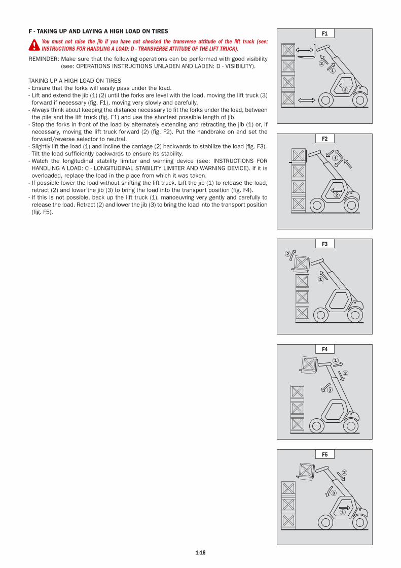
F - TAKING UP AND LAYING A HIGH LOAD ON TIRES
You must not raise the jib if you have not checked the transverse attitude of the lift truck (see:INSTRUCTIONS FOR HANDLING A LOAD: D - TRANSVERSE ATTITUDE OF THE LIFT TRUCK).
REMINDER: Make sure that the following operations can be performed with good visibility (see: OPERATIONS INSTRUCTIONS UNLADEN AND LADEN: D - VISIBILITY).
TAKING UP A HIGH LOAD ON TIRES- Ensure that the forks will easily pass under the load.- Lift and extend the jib (1) (2) until the forks are level with the load, moving the lift truck (3) forward if necessary (fig. F1), moving very slowly and carefully.
- Always think about keeping the distance necessary to fit the forks under the load, between the pile and the lift truck (fig. F1) and use the shortest possible length of jib.
- Stop the forks in front of the load by alternately extending and retracting the jib (1) or, if necessary, moving the lift truck forward (2) (fig. F2). Put the handbrake on and set the forward/reverse selector to neutral.
- Slightly lift the load (1) and incline the carriage (2) backwards to stabilize the load (fig. F3).- Tilt the load sufficiently backwards to ensure its stability.- Watch the longitudinal stability limiter and warning device (see: INSTRUCTIONS FOR HANDLING A LOAD: C - LONGITUDINAL STABILITY LIMITER AND WARNING DEVICE). If it is overloaded, replace the load in the place from which it was taken.
- If possible lower the load without shifting the lift truck. Lift the jib (1) to release the load, retract (2) and lower the jib (3) to bring the load into the transport position (fig. F4).
- If this is not possible, back up the lift truck (1), manoeuvring very gently and carefully to release the load. Retract (2) and lower the jib (3) to bring the load into the transport position (fig. F5).
1
2
3
F1
1
2
F2
1
2
F3
1
3
2
F4
1
2
3
F5

1-17
LAYING A HIGH LOAD ON TYRES- Approach the load in the transport position in front of the pile (fig. F6).- Put the handbrake on and set the forward/reverse selector to neutral.- Lift and extend the jib (1) (2) until the load is above the pile, while keeping an eye on the longitudinal stability limiter and warning device (see: INSTRUCTIONS FOR HANDLING A LOAD: C - LONGITUDINAL STABILITY LIMITER AND WARNING DEVICE). If necessary, move the lift truck (3) forward (fig. F7), driving very slowly and carefully.
- Place the load in a horizontal position and lay it down on the pile by lowering and retracting the jib (1) (2) in order to position the load correctly (fig. F8).
- If possible, release the fork by alternately retracting and raising the jib (1) (fig. F9). Then set the forks into transport position.
- If this is not possible, reverse the lift truck (1) very slowly and carefully to release the forks (fig. F10). Then set them into transport position.
F6
1
2
3
F7
1
2
F8
1
F9
1
F10
1-18
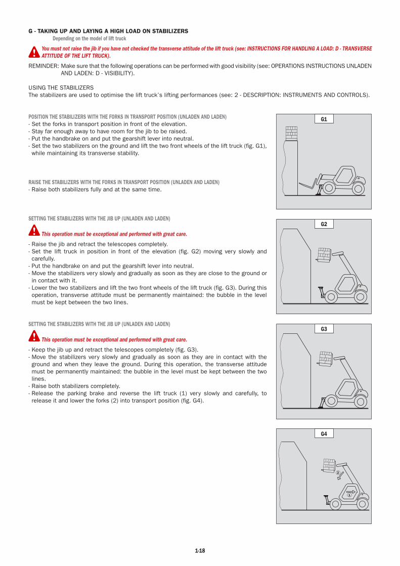
G - TAKING UP AND LAYING A HIGH LOAD ON STABILIZERSDepending on the model of lift truck
You must not raise the jib if you have not checked the transverse attitude of the lift truck (see: INSTRUCTIONS FOR HANDLING A LOAD: D - TRANSVERSEATTITUDE OF THE LIFT TRUCK).
REMINDER: Make sure that the following operations can be performed with good visibility (see: OPERATIONS INSTRUCTIONS UNLADEN AND LADEN: D - VISIBILITY).
USING THE STABILIZERSThe stabilizers are used to optimise the lift truck’s lifting performances (see: 2 - DESCRIPTION: INSTRUMENTS AND CONTROLS).
POSITION THE STABILIZERS WITH THE FORKS IN TRANSPORT POSITION (UNLADEN AND LADEN)- Set the forks in transport position in front of the elevation.- Stay far enough away to have room for the jib to be raised.- Put the handbrake on and put the gearshift lever into neutral.- Set the two stabilizers on the ground and lift the two front wheels of the lift truck (fig. G1), while maintaining its transverse stability.
RAISE THE STABILIZERS WITH THE FORKS IN TRANSPORT POSITION (UNLADEN AND LADEN)- Raise both stabilizers fully and at the same time.
SETTING THE STABILIZERS WITH THE JIB UP (UNLADEN AND LADEN)
This operation must be exceptional and performed with great care.
- Raise the jib and retract the telescopes completely.- Set the lift truck in position in front of the elevation (fig. G2) moving very slowly and carefully.
- Put the handbrake on and put the gearshift lever into neutral.- Move the stabilizers very slowly and gradually as soon as they are close to the ground or in contact with it.
- Lower the two stabilizers and lift the two front wheels of the lift truck (fig. G3). During this operation, transverse attitude must be permanently maintained: the bubble in the level must be kept between the two lines.
SETTING THE STABILIZERS WITH THE JIB UP (UNLADEN AND LADEN)
This operation must be exceptional and performed with great care.
- Keep the jib up and retract the telescopes completely (fig. G3).- Move the stabilizers very slowly and gradually as soon as they are in contact with the ground and when they leave the ground. During this operation, the transverse attitude must be permanently maintained: the bubble in the level must be kept between the two lines.
- Raise both stabilizers completely.- Release the parking brake and reverse the lift truck (1) very slowly and carefully, to release it and lower the forks (2) into transport position (fig. G4).
G1
G2
G3
1
2
G4

1-19
TAKING UP A HIGH LOAD ON STABILIZERS- Make sure the forks will fit easily under the load.- Check the position of the lift truck with respect to the load and make a test run, if necessary, without taking the load.
- Raise and extend the jib (1) (2) until the forks are at the level of the load (fig. G5).- Block the forks in front of the load by alternately using the controls to extend and lower the jib (1) (fig. G6).
- Lift the load slightly (1) and tilt the carriage (2) backwards to stabilise the load (fig. G7).- Monitor the longitudinal stability limiter and warning device (see: INSTRUCTIONS FOR HANDLING A LOAD: C - LONGITUDINAL STABILITY LIMITER AND WARNING DEVICE). If it is overloaded, set the load down in the place from where it was taken.
- If possible lower the load without moving the lift truck. Raise the jib (1) to release the load, retract (2) and lower the jib (3) to set the load into transport position (fig. G8).
LAYING A HIGH LOAD ON STABILIZERS- Raise and extend the jib (1) (2) until the load is above the elevation (fig. G9), while monitoring the longitudinal stability limiter and warning device (see: INSTRUCTIONS FOR HANDLING A LOAD: C - LONGITUDINAL STABILITY LIMITER AND WARNING DEVICE).
- Position the load horizontally and release it by lowering and retracting the jib (1) (2) to position the load correctly (fig. G10).
- Release the forks by alternating retracting and raising the jib (3) (fig. G11).- If possible, set the jib in transport position without moving the lift truck.
1
2
G5
1
G6
1
2
3
G8
1
2
G7
1
2
G9
3
G11
1
2
G10

1-20
H - TAKING UP AND LAYING DOWN A SUSPENDED LOAD
WARNING: Failure to follow the above instructions may lead the lift truck to loose stability and overturn.
MUST be used with a lift truck equipped with an operational hydraulic movement cut-out device.
CONDITIONS OF USE- The length of the sling or the chain shall be as short as possible to limit swinging of the load.- Lift the load vertically along its axis, never by pulling sideways or lengthways.
HANDLING WITHOUT MOVING THE LIFT TRUCK- Whether on stabilisers or on tyres, the lateral attitude must not exceed 1 % and the longitudinal attitude must not exceed 5%, the bubble of the level must be held at “0”.
- Ensure that the wind speed is not higher than 10 m/s.- Ensure that there is no one between the load and the lift truck.
I - TRAVELLING WITH A SUSPENDED LOAD- Before moving, inspect the terrain in order to avoid excessive slopes and cross-falls, bumps and potholes, or soft ground.- Ensure that the wind speed is not higher than 10 m/s.- The lift truck must not travel at more than 0.4 m/s (1.5 km/h, i.e., one quarter walking speed).- Drive and stop the lift truck gently and smoothly to minimise swinging of the load.- Carry the load a few centimetres above the ground (max. 30 cm) the shortest possible jib length. Do not exceed the offset indicated on the load chart. If the load begins to swing excessively, do not hesitate to stop and lower the jib to set down the load.
- Before moving the lift truck, check the longitudinal stability limiter and warning device (see: 2 - DESCRIPTION: INSTRUMENTS AND CONTROLS), only the green LEDs and possibly the yellow LEDs should be lit.
- During transport, the lift truck operator must be assisted by a person on the ground (standing a minimum of 3 m from the load), who will limit swinging of the load using a bar or a rope. Ensure that this person is always clearly in view.
- The lateral attitude must not exceed 5%, the bubble in the level must be kept between the two “MAX.” marks- The longitudinal attitude must not exceed 15%, with the load facing uphill, and 10%, with the load facing downhill.- The jib angle must not exceed 45°.- If the first red LED of the longitudinal stability limiter and warning device (see: 2 - DESCRIPTION: INSTRUMENTS AND CONTROLS) comes on while travelling, gently bring the lift truck to a stop and stabilise the load. Retract the telescope to reduce the offset of the load.
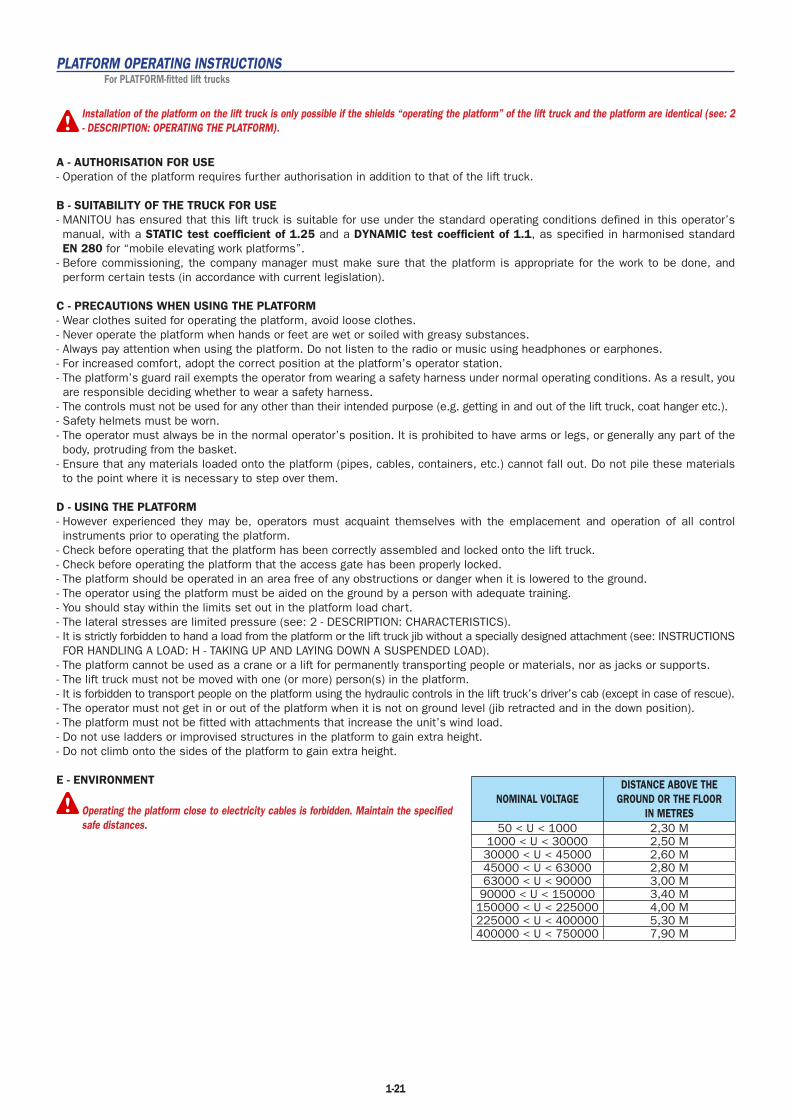
1-21
PLATFORM OPERATING INSTRUCTIONSFor PLATFORM-fitted lift trucks
Installation of the platform on the lift truck is only possible if the shields “operating the platform” of the lift truck and the platform are identical (see: 2- DESCRIPTION: OPERATING THE PLATFORM).
A - AUTHORISATION FOR USE- Operation of the platform requires further authorisation in addition to that of the lift truck.
B - SUITABILITY OF THE TRUCK FOR USE- MANITOU has ensured that this lift truck is suitable for use under the standard operating conditions defined in this operator’s manual, with a STATIC test coefficient of 1.25 and a DYNAMIC test coefficient of 1.1, as specified in harmonised standard EN 280 for “mobile elevating work platforms”.
- Before commissioning, the company manager must make sure that the platform is appropriate for the work to be done, and perform certain tests (in accordance with current legislation).
C - PRECAUTIONS WHEN USING THE PLATFORM- Wear clothes suited for operating the platform, avoid loose clothes.- Never operate the platform when hands or feet are wet or soiled with greasy substances.- Always pay attention when using the platform. Do not listen to the radio or music using headphones or earphones.- For increased comfort, adopt the correct position at the platform’s operator station.- The platform’s guard rail exempts the operator from wearing a safety harness under normal operating conditions. As a result, you are responsible deciding whether to wear a safety harness.
- The controls must not be used for any other than their intended purpose (e.g. getting in and out of the lift truck, coat hanger etc.).- Safety helmets must be worn.- The operator must always be in the normal operator’s position. It is prohibited to have arms or legs, or generally any part of the body, protruding from the basket.
- Ensure that any materials loaded onto the platform (pipes, cables, containers, etc.) cannot fall out. Do not pile these materials to the point where it is necessary to step over them.
D - USING THE PLATFORM- However experienced they may be, operators must acquaint themselves with the emplacement and operation of all control instruments prior to operating the platform.
- Check before operating that the platform has been correctly assembled and locked onto the lift truck.- Check before operating the platform that the access gate has been properly locked.- The platform should be operated in an area free of any obstructions or danger when it is lowered to the ground.- The operator using the platform must be aided on the ground by a person with adequate training.- You should stay within the limits set out in the platform load chart.- The lateral stresses are limited pressure (see: 2 - DESCRIPTION: CHARACTERISTICS).- It is strictly forbidden to hand a load from the platform or the lift truck jib without a specially designed attachment (see: INSTRUCTIONS FOR HANDLING A LOAD: H - TAKING UP AND LAYING DOWN A SUSPENDED LOAD).
- The platform cannot be used as a crane or a lift for permanently transporting people or materials, nor as jacks or supports.- The lift truck must not be moved with one (or more) person(s) in the platform.- It is forbidden to transport people on the platform using the hydraulic controls in the lift truck’s driver’s cab (except in case of rescue).- The operator must not get in or out of the platform when it is not on ground level (jib retracted and in the down position).- The platform must not be fitted with attachments that increase the unit’s wind load.- Do not use ladders or improvised structures in the platform to gain extra height.- Do not climb onto the sides of the platform to gain extra height.
E - ENVIRONMENT
Operating the platform close to electricity cables is forbidden. Maintain the specifiedsafe distances.
NOMINAL VOLTAGEDISTANCE ABOVE THE
GROUND OR THE FLOOR IN METRES
50 < U < 1000 2,30 M1000 < U < 30000 2,50 M30000 < U < 45000 2,60 M45000 < U < 63000 2,80 M63000 < U < 90000 3,00 M
90000 < U < 150000 3,40 M150000 < U < 225000 4,00 M225000 < U < 400000 5,30 M400000 < U < 750000 7,90 M
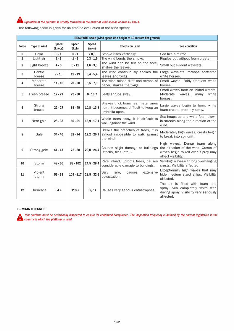
1-22
Operation of the platform is strictly forbidden in the event of wind speeds of over 45 km/h.
- The following scale is given for an empiric evaluation of the wind speed:
BEAUFORT scale (wind speed at a height of 10 m from flat ground)
Force Type of windSpeed(knots)
Speed(kph)
Speed(m/s)
Effects on Land Sea condition
0 Calm 0 - 1 0 - 1 < 0,3 Smoke rises vertically. Sea like a mirror.1 Light air 1 - 3 1 - 5 0,3 - 1,5 The wind bends the smoke. Ripples but without foam crests.
2 Light breeze 4 - 6 6 - 11 1,6 - 3,3The wind can be felt on the face, shakes the leaves.
Small but evident wavelets.
3Gentlebreeze
7 - 10 12 - 19 3,4 - 5,4The wind continuously shakes the leaves and twigs.
Large wavelets Perhaps scattered white horses.
4Moderate
breeze11 - 16 20 - 28 5,5 - 7,9
The wind raises dust and scraps of paper, shakes the twigs.
Small waves. Fairly frequent white horses.
5 Fresh breeze 17 - 21 29 - 38 8 - 10,7 Leafy shrubs sway.Small waves form on inland waters. Moderate waves, many white horses.
6Strong breeze
22 - 27 39 - 49 10,8 - 13,8Shakes thick branches, metal wires hum, it becomes difficult to keep an umbrella open.
Large waves begin to form, white foam crests, probably spray.
7 Near gale 28 - 33 50 - 61 13,9 - 17,1Whole trees sway, it is difficult to walk against the wind.
Sea heaps up and white foam blown in streaks along the direction of the wind.
8 Gale 34 - 40 62 - 74 17,2 - 20,7Breaks the branches of trees, it is almost impossible to walk against the wind.
Moderately high waves, crests begin to break into spindrift.
9 Strong gale 41 - 47 75 - 88 20,8 - 24,4Causes slight damage to buildings (stacks, tiles, etc..).
High waves. Dense foam along the direction of the wind. Crests of waves begin to roll over. Spray may affect visibility.
10 Storm 48 - 55 89 - 102 24,5 - 28,4Rare inland, uproots trees, causes considerable damage to buildings.
Very high waves with long overhanging crests. Visibility affected.
11Violent storm
56 - 63 103 - 117 28,5 - 32,6Very rare, causes extensive devastation.
Exceptionally high waves that may hide medium sized ships. Visibility affected.
12 Hurricane 64 + 118 + 32,7 + Causes very serious catastrophes.
The air is filled with foam and spray. Sea completely white with driving spray. Visibility very seriously affected.
F - MAINTENANCE
Your platform must be periodically inspected to ensure its continued compliance. The inspection frequency is defined by the current legislation in thecountry in which the platform is used.

1-23
INSTRUCTIONS FOR USING THE RADIO-CONTROLFor lift trucks with RC radio control
HOW TO USE THE RADIO-CONTROLSAFETY INSTRUCTIONS- This radio-control consists of electronic and mechanical safety elements. It cannot receive commands from another transmitter because the internal encoding is unique to each radio-control.
If it is used improperly or incorrectly, there is a risk of danger to:- The physical and mental health of the user or others.- The lift truck and other neighbouring items.
Everyone working with this radio-control:- Must be qualified in line with current regulations and therefore appropriately trained.- Must follow this instruction manual as closely as possible.
- The system is used to control the lift truck remotely via radio waves. Commands are also transmitted if the lift truck is out of sight (behind an obstacle or a building for example), this is why:
• After stopping the truck and removing the key button (only possible when it is stationary), always place the transmitter in a safe, dry place.
• Before performing any installation, servicing or repair work, always switch off power sources (in particular, electric welding devices and electric head units on hydraulic distributors must be disconnected at each section).
• Never remove or alter the safety devices (such as the hand-guard frame, key, emergency stop button, etc.).
Never drive the lift truck if it is not continuously and perfectly within view of the operator!
- Before leaving the transmitter, the operator must make sure that it cannot be used by an unauthorized third person: either by removing the key button from the transmitter or locking it in an inaccessible place.
- The user must ensure that the instruction manual is accessible at all times and that operators have read and understood it.
INSTRUCTIONS- Take up position in a stable place with no risk of slipping.- Before using the transmitter, make sure there is nobody within the working area.- Only use the transmitter with its carrying device or installed correctly on the platform.
When you remove the transmitter, remove the accumulator and key button so that it cannot be used accidentally or deliberately by anyone else.
PROTECTIVE DEVICES- The lift truck will be immobilised within 450 milliseconds (approx. 0.5 second) at most:
• If the transmitter emergency stop button (50 milliseconds), or the one on the lift is pressed.• If the transmission distance of the radio waves is exceeded.• If the transmitter is faulty.• If an interfering radio signal is received from elsewhere.• If the accumulator is removed from its housing in the transmitter.• If the accumulator reaches the end of its autonomy.• If the transmitter is switched off by turning the key button to stop.
- These protective devices are provided for the safety of personnel and property and must never be altered, removed or bypassed in any way whatsoever!
- The hand-guard frame prevents external action on a manipulator (if the transmitter falls, for example, or if the operator leans on a guard-rail).
- An electronic safety device prevents radio transmission from being initiated if the manipulators are not mechanically and electrically at rest and if the internal combustion engine speed selector is not set to idle.
In an emergency, press the transmitter emergency stop button immediately ; then follow the manual’s instructions (see: 2 - DESCRIPTION: INSTRUMENTSAND CONTROLS).

1-24
MAINTENANCE INSTRUCTIONS OF THE LIFT TRUCK
GENERAL INSTRUCTIONS
- Ensure the area is sufficiently ventilated before starting the lift truck.- Wear clothes suitable for the maintenance of the lift truck, avoid wearing jewellery and loose clothes. Tie and protect your hair, if necessary.
- Stop the I.C. engine and remove the ignition key, when an intervention is necessary.- Read the operator’s manual carefully.- Carry out all repairs immediately, even if the repairs concerned are minor.- Repair all leaks immediately, even if the leak concerned is minor.- Make sure that the disposal of process materials and of spare parts is carried out in total safety and in a ecological way.- Be careful of the risk of burning and splashing (exhaust, radiator, I.C. engine, etc.).
MAINTENANCE
- Perform the periodic service (see: 3 - MAINTENANCE) to keep your lift truck in good working conditions. Failure to perform the periodic service may cancel the contractual guarantee.
MAINTENANCE LOGBOOK- The maintenance operations carried out in accordance with the recommendations given in part: 3 - MAINTENANCE and the other inspection, servicing or repair operations or modifications performed on the lift truck or its attachments shall be recorded in a maintenance logbook. The entry for each operation shall include details of the date of the works, the names of the individuals or companies having performed them, the type of operation and its frequency, if applicable. The part numbers of any lift truck items replaced shall also be indicated.
LUBRICANT AND FUEL LEVELS
- Use the recommended lubricants (never use contaminated lubricants).- Do not fill the fuel tank when the I.C. engine is running.- Only fill up the fuel tank in areas specified for this purpose.- Do not fill the fuel tank to the maximum level.- Do not smoke or approach the lift truck with a flame, when the fuel tank is open or is being filled.
HYDRAULIC
- Any work on the load handling hydraulic circuit is forbidden except for the operations described in part: 3 - MAINTENANCE.- Do not attempt to loosen unions, hoses or any hydraulic component with the circuit under pressure.
BALANCING VALVE: It is dangerous to change the setting and remove the balancing valves or safety valves which may be fitted to your lift truck cylinders.These operations must only be performed by approved personnel (consult your dealer).
The HYDRAULIC ACCUMULATORS that may be fitted on your lift truck are pressurized units. Removing these accumulators and their pipework is adangerous operation and must only be performed by approved personnel (consult your dealer).
ELECTRICITY
- Do not short-circuit the starter relay to start the IC engine. If the forward/reverse selector is not in neutral and the parking brake is not engaged, the lift truck may suddenly start to move.
- Do not drop metallic items on the battery.- Disconnect the battery before working on the electrical circuit.
1-25
WELDING
- Disconnect the battery before any welding operations on the lift truck.- When carrying out electric welding work on the lift truck, connect the negative cable from the equipment directly to the part being welded, so as to avoid high tension current passing through the alternator.
- Never carry out welding or work which gives off heat on an assembled tyre. The heat would increase the pressure which could cause the tyre to explode.
- If the lift truck is equipped with an electronic control unit, disconnect this before starting to weld, to avoid the risk of causing irreparable damage to electronic components.
WASHING THE LIFT TRUCK
- Clean the lift truck or at least the area concerned before any intervention.- Remember to close and lock all accesses to the lift truck (doors, windows, cowls…).- During washing, avoid the articulations and electrical components and connections.- If necessary, protect against penetration of water, steam or cleaning agents, components susceptible of being damaged, particularly electrical components and connections and the injection pump.
- Clean the lift truck of any fuel, oil or grease trace.
FOR ANY INTERVENTION OTHER THAN REGULAR MAINTENANCE, CONSULT YOUR DEALER.
1-26
IF THE LIFT TRUCK IS NOT TO BE USED FOR A LONG TIME
INTRODUCTION
The following recommendations are intended to prevent the lift truck from being damaged when it is withdrawn from service for an extended period.For these operations, we recommend the use of a MANITOU protective product, reference 603726.Instructions for using the product are given on the packaging.
Procedures to follow if the lift truck is not to be used for a long time and for starting it up again afterwards must be performed by your dealership.
PREPARING THE LIFT TRUCK
- Clean the lift truck thoroughly.- Check and repair any leakage of fuel, oil, water or air.- Replace or repair any worn or damaged parts.- Wash the painted surfaces of the lift truck in clear and cold water and wipe them.- Touch up the paintwork if necessary.- Shut down the lift truck (see: OPERATING INSTRUCTIONS UNLADEN AND LADEN).- Make sure the jib cylinder rods are all in retracted position.- Release the pressure in the hydraulic circuits.
PROTECTING THE I.C. ENGINE
- Fill the tank with fuel (see: 3 - MAINTENANCE: A - DAILY OR EVERY 10 HOURS SERVICE).- Empty and replace the cooling liquid (see: 3 - MAINTENANCE: F - EVERY 2000 HOURS SERVICE).- Leave the I.C. engine running at idling speed for a few minutes, then switch off.- Replace the I.C. engine oil and oil filter (see: 3 - MAINTENANCE: D - EVERY 500 HOURS SERVICE).- Add the protective product to the engine oil.- Run the I.C. engine for a short time so that the oil and cooling liquid circulate inside.- Disconnect the battery and store it in a safe place away from the cold, after charging it to a maximum.- Remove the injectors and spray the protective product into each cylinder for two seconds with the piston in low neutral position.- Turn the crankshaft once slowly and refit the injectors (see I.C. engine REPAIR MANUAL).- Remove the intake hose from the manifold or turbocharger and spray the protective product into the manifold or turbocharger.- Cap the intake manifold or turbocharger hole with waterproof adhesive tape.- Remove the exhaust pipe and spray the protective product into the exhaust manifold or turbocharger.- Refit the exhaust pipe and block the outlet with waterproof adhesive tape.NOTE: The spray time is noted on the product packaging and must be increased by 50 % for turbo engines.- Open the filler plug, spray the protective product around the rocker arm shaft and refit the filler plug.- Cap the fuel tank using waterproof adhesive tape.- Remove the drive belts and store them in a safe place.- Disconnect the engine cut-off solenoid on the injection pump and carefully insulate the connection.
PROTECTING THE LIFT TRUCK
- Set the lift truck on axle stands so that the tyres are not in contact with the ground and release the handbrake.- Protect cylinder rods which will not be retracted, from corrosion.- Wrap the tyres.NOTE: If the lift truck is to be stored outdoors, cover it with a waterproof tarpaulin.

1-27
BRINGING THE LIFT TRUCK BACK INTO SERVICE
- Remove the waterproof adhesive tape from all the holes.- Refit the intake hose.- Refit and reconnect the battery.- Remove the protection from the cylinder rods.- Perform the daily service (see: 3 - MAINTENANCE: A - DAILY OR EVERY 10 HOURS SERVICE).- Put the handbrake on and remove the axle stands.- Empty and replace the fuel and replace the fuel filter (see: 3 - MAINTENANCE: D - EVERY 500 HOURS SERVICE).- Refit and set the tension in the drive belts (see: 3 - MAINTENANCE: C - EVERY 250 HOURS SERVICE).- Turn the I.C. engine using the starter, to allow the oil pressure to rise.- Reconnect the engine cut-off solenoid.- Lubricate the lift truck completely (see: 3 - MAINTENANCE: SERVICING SCHEDULE).
Make sure the area is adequately ventilated before starting up the lift truck.
- Start up the lift truck, following the safety instructions and regulations (see: OPERATING INSTRUCTIONS UNLADEN AND LADEN).- Run all the jib’s hydraulic movements, concentrating on the ends of travel for each cylinder.

1-28

2-1
2 - DESCRIPTION

2-2

2-3
TABLE OF CONTENTS
IDENTIFICATION OF THE LIFT TRUCK 2-6
CHARACTERISTICS 2-8
FRONT AND REAR TIRES 2-10
DIMENSIONS AND LOAD CHART 2-12
INSTRUMENTS AND CONTROLS 2-14
TOWING PIN AND HOOK 2-30
DESCRIPTION AND USE OF THE OPTIONS 2-32
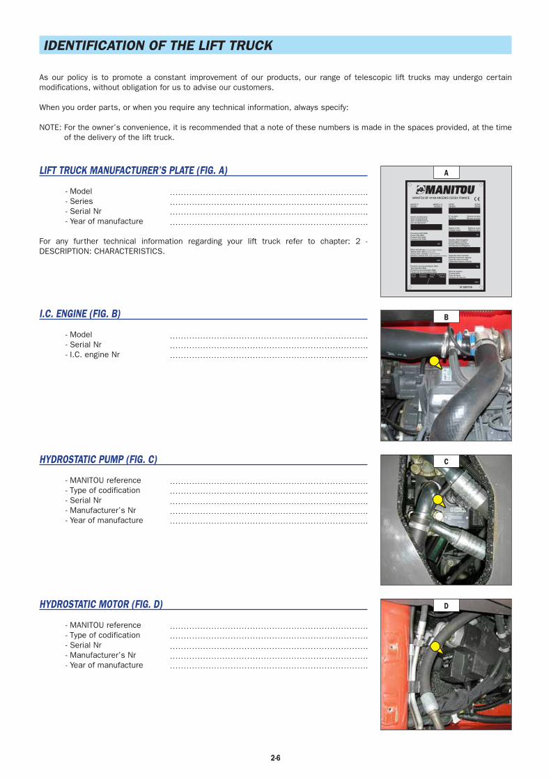
2-6
IDENTIFICATION OF THE LIFT TRUCK
As our policy is to promote a constant improvement of our products, our range of telescopic lift trucks may undergo certain modifications, without obligation for us to advise our customers.
When you order parts, or when you require any technical information, always specify:
NOTE: For the owner’s convenience, it is recommended that a note of these numbers is made in the spaces provided, at the time of the delivery of the lift truck.
LIFT TRUCK MANUFACTURER’S PLATE (FIG. A)
- Model- Series- Serial Nr- Year of manufacture
For any further technical information regarding your lift truck refer to chapter: 2 - DESCRIPTION: CHARACTERISTICS.
I.C. ENGINE (FIG. B)
- Model- Serial Nr- I.C. engine Nr
HYDROSTATIC PUMP (FIG. C)
- MANITOU reference- Type of codification- Serial Nr- Manufacturer’s Nr- Year of manufacture
HYDROSTATIC MOTOR (FIG. D)
- MANITOU reference- Type of codification- Serial Nr- Manufacturer’s Nr- Year of manufacture
MANITOU BF 44158 ANCENIS CEDEX FRANCE
N°283709
MODELEMODEL
MODELLOMODELO
SERIESERIES
SERIESERIE
N° de sérieSerial Nr
Numero di serieNúmero de serie
Masse à videUnladen mass
Numéro d'homologationHomologation numberNumero d'omologazioneContraseña homologacion
Capacité maxi nominaleNominal maximum capacityCapacità maxi nominaleCapacidad máximo nominal
Effort de tractionTractive effortForza di trainoEsfuerzo de traccion
Massa a vuotoMasa en vacio
Année de fabricationYear of manufactureAnno di fabbricazioneAño de fabricacion
Puissance ISO 3046Power ISO 3046Potenza ISO 3046Potencia ISO 3046
Effort vertical max. (sur accrochage remorque)
Vertical max. effort (on trailer hook)
Carico max. verticale (sul gancio di traino)
Esfuerzo vertical max. (sobre el gancho de remolque)
Pression des pneumatiques (Bar)Tyre pressure (Bar)Pressione per pneumatici (Bar)Presion de los neumáticos (Bar)
kW
daN
AvantFront
AnterioreAdelante
ArrièreRear
PosterioreTrasero
kg
kg
daN
A
B
D
C
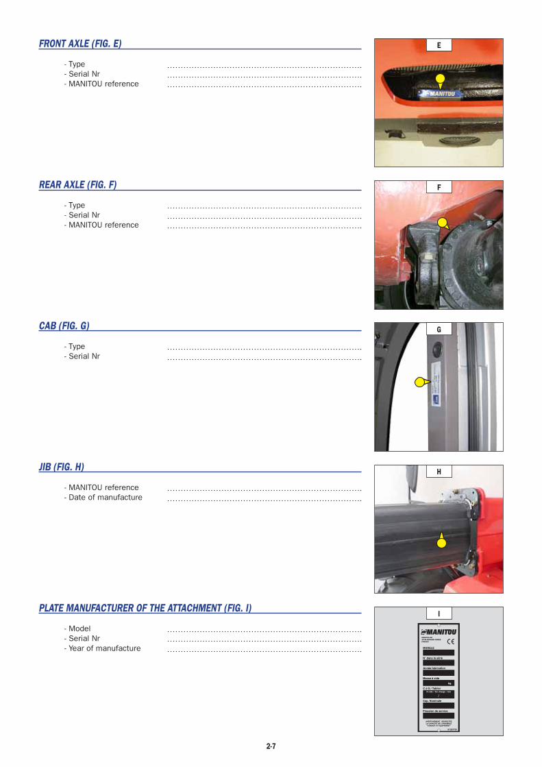
2-7
FRONT AXLE (FIG. E)
- Type- Serial Nr- MANITOU reference
REAR AXLE (FIG. F)
- Type- Serial Nr- MANITOU reference
CAB (FIG. G)
- Type- Serial Nr
JIB (FIG. H)
- MANITOU reference- Date of manufacture
PLATE MANUFACTURER OF THE ATTACHMENT (FIG. I)
- Model- Serial Nr- Year of manufacture
N 207701
MODELE
N dans la série
Année fabrication
Masse à vide
C d G / Tablier
Cap. Nominale
Pression de service
AVERTISSEMENT : RESPECTEZLA CAPACITE DE L'ENSEMBLE"CHARIOT ET EQUIPEMENT"
kg
A vide / En charge : mm
MANITOU BF44158 ANCENIS CEDEXFRANCE
I
G
H
E
F

2-8
TRANSMISSIONHydrostatic pump DANFOSS
Type Variable displacement pistonForward/reverse selector Electro-hydraulicNumber of forward speeds 2 (1 low and 1 high)Number of reverse speeds 2 (1 low and 1 high)Main pump
MAX./MIN. displacement cm3/rev 0 - 45MAX. flow rate l/mn (gl/mn) 117 (30.9)Working pressure bar (psi) 400 (5802)
Boost pumpCapacity cm3/rev 12MAX. flow rate l/mn (gl/mn) 31 (8)Boost pressure MAX. R.P.M. bar (psi) 24 (348) (transmission in neutral)
Hydrostatic motor DANFOSSType Variable displacement pistonMAX./MIN. displacement cm3/rev 23 - 80
Gear box DANAFront axle DANA
Differential 45 % limited slip differentialRear axle DANA
Differential Without lockingDrive wheels 4RM Permanent
Switch for 2/4 drive wheels NoFront tyres DUNLOP
Size 12.0-18 12PR T86 Stabilarge TUBELESSPressure bar (psi) 4,2 (61)
Rear tyres DUNLOPSize 12.0-18 12PR T86 Stabilarge TUBELESSPressure bar (psi) 4,2 (61)
CHARACTERISTICS
SOUND AND VIBRATIONLevel of sound pressure in the driver’s cab LpA
(according to standard NF EN 12053)dB 76 (cab closed)
Level of sound power ensured in the LwA environment(according to directive 2000/14/EC modified by directive 2005/88/EC)
dB104 (measured)104 (ensured)
Average weighted acceleration on driver’s body(according to standard NF EN 13059)
m/s2
The average weighted acceleration transmitted to the driver’s hand/arm system(according to standard ISO 5349-2)
m/s2(ft/s2) < 2,5 (< 8.2)
I.C. ENGINEType KUBOTA V3307Fuel DieselNumber of cylinders 4 in lineSuction SuperchargedInjection system DirectIgnition sequence 1.3.4.2Capacity cm3 (cu/in) 3331 (203.3)Bore and stroke mm (in) 94 x 120 (3.7 x 4.7)Compression ratio 20Nominal rating loaded rpm 2600Rating slow unladen rpm 895Max. rating unladen rpm 2800Power ISO 3046-1 cv- kW 75 - 55,4Power SAE J 1995 cv- kW 75 - 55,4Maximum torque ISO 3046-1 N.m 265 to 1400 rpmAir cleaner μm 3Type of cooling By waterFan Puller
ELECTRIC CIRCUIT
Battery Standard 12 V - 110 Ah - 750 A ENOption - - - - - -
Alternator 12 V - 80 AType A5TA59 77B
Starter 12 V - 3 kWType M008T50671

2-9
HYDRAULIC CIRCUITHydraulic pump
Type Double gear1st chamber 2nd chamber
Capacity cm3 (cu/in) 31 (1.9) 11 (.67)Max. rating capacity unladen l/mn (gl/mn) 86 (23) 31 (8)Flow rate at 1600 rpm l/mn (gl/mn) 49 (13) 18 (5)
FiltrationReturn μm 10 10Suction μm 125 125
Maximum service pressure bar (psi) 235 (3408)Telescoping circuit bar (psi) 235 / 235 (3408)Lifting circuit bar (psi) 235 / 235 (3408)Tilt circuit bar (psi) 245 / 245 (3553)Attachment circuit bar (psi) 235 (3408)Steering circuit bar (psi) 140 (2031)
BRAKE CIRCUITService brake Non-servo hydraulic brake
Type of brake Multidisk brake immersed in oilType of control By foot on front axle
Parking brake Low pressure hydraulic brakeType of brake Multidisc brake immersed in oilType of control Switch-operated electro-hydraulic
HYDRAULIC MOVEMENTSLongitudinal stability limiter and warning device ElectronicLifting motions (jib retracted)
Unladen lifting s - m/mn 7,3 - 32,1Laden lifting s - m/mn 7,45 - 31,4Unladen lowering s - m/mn 4,95 - 47,3Laden lowering s - m/mn 5 - 46,8
Telescoping motions (jib raised)Unladen extending s - m/mn 5,2 - 24,8Laden extending s - m/mn 5,3 - 25,3Unladen retracting s - m/mn 3,7 - 35,5Laden retracting s - m/mn 3,75 - 35
Tilting movementsUnladen digging s - °/s 3,2 - 40,1Forward tilting unladen s - °/s 3,2 - 40,1
SPECIFICATIONS AND WEIGHTSSpeed of movement for lift truck in standard configuration on flat ground (except particular conditions)
Front unladen 1 low km/h (mph) 9 (5.6) 1 high km/h (mph) 25 (15.5)Rear unladen 1 low km/h (mph) 9 (5.6) 1 high km/h (mph) 25 (15.5)
Standard attachment PFB 25 N MT 1020Weight of attachment (without forks) kg (lbs) 80 (176)Weight of forks (each one) kg (lbs) 76 (168)
Rated capacity with standard attachment kg (lbs) 2500 (5512)Tipping load at maximum reach on tyres kgDistance from the centre of gravity from the load to the lug of the forks Mm (in) 500 (20) Standard lifting height Mm (in) 5900 (232)Lift truck weight without attachment kg (lbs) 4690 (10340)Lift truck weight with standard attachment
Unladen kg (lbs) 4922 (10851)At rated load kg (lbs) 7422 (16363)
Weight per axle with standard attachment (transport position)Front unladen kg (lbs) 2362 (5207)Rear unladen kg (lbs) 2560 (5644)Front rated load kg (lbs) 6622 (14599)Rear rated load kg (lbs) 800 (1764)
Weight per axle with standard attachment (jib extended)Front rated load kg (lbs) 5212 (11490)Rear rated load kg (lbs) 510 (1124)
Authorised gross vehicle weight daN (lbf) 21000 (47210)Drag strain on the coupling hook
Unladen (sliding) daNAt rated load (transmission setting) daN
Pull strain with open carrier (according to standard ISO 8313) daN (lbf) 4205 (945)
ezunig
Rectangle
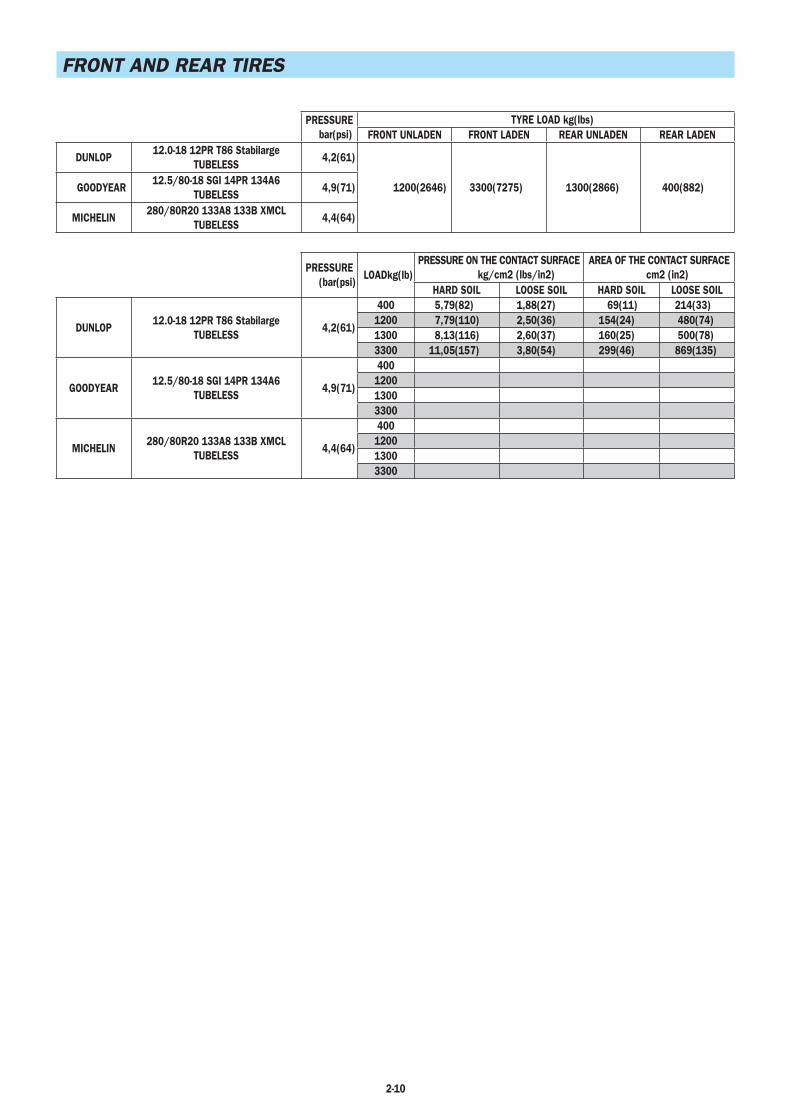
2-10
FRONT AND REAR TIRES
PRESSUREbar(psi)
TYRE LOAD kg(lbs)FRONT UNLADEN FRONT LADEN REAR UNLADEN REAR LADEN
DUNLOP12.0-18 12PR T86 Stabilarge
TUBELESS 4,2(61)
1200(2646) 3300(7275) 1300(2866) 400(882)GOODYEAR12.5/80-18 SGI 14PR 134A6
TUBELESS4,9(71)
MICHELIN280/80R20 133A8 133B XMCL
TUBELESS4,4(64)
PRESSURE(bar(psi)
LOADkg(lb)PRESSURE ON THE CONTACT SURFACE
kg/cm2 (lbs/in2)AREA OF THE CONTACT SURFACE
cm2 (in2)HARD SOIL LOOSE SOIL HARD SOIL LOOSE SOIL
DUNLOP12.0-18 12PR T86 Stabilarge
TUBELESS4,2(61)
400 5,79(82) 1,88(27) 69(11) 214(33)1200 7,79(110) 2,50(36) 154(24) 480(74)1300 8,13(116) 2,60(37) 160(25) 500(78)3300 11,05(157) 3,80(54) 299(46) 869(135)
GOODYEAR12.5/80-18 SGI 14PR 134A6
TUBELESS4,9(71)
400120013003300
MICHELIN280/80R20 133A8 133B XMCL
TUBELESS4,4(64)
400120013003300

2-11
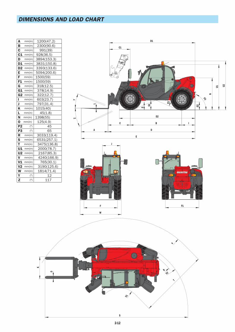
2-12
DIMENSIONS AND LOAD CHART
A mm(in) 1200(47.2)B mm(in) 2300(90.6)C mm(in) 991(39)C1 mm(in) 928(36.5)D mm(in) 3894(153.3)D1 mm(in) 3831(150.8)D2 mm(in) 3393(133.6)E mm(in) 5094(200.6)F mm(in) 1500(59)F1 mm(in) 1500(59)G mm(in) 318(12.5)G1 mm(in) 378(14.9)G2 mm(in) 322(12.7)I mm(in) 603(23.7)J mm(in) 797(31.4)K mm(in) 1015(40)L mm(in) 45(1.8)N mm(in) 1398(55)O mm(in) 125(4.9)P2 (°) 45P3 (°) 65R mm(in) 3033(119.4)S mm(in) 6531(257.1)T mm(in) 3475(136.8)U1 mm(in) 2000(78.7)U2 mm(in) 2167(85.3)V mm(in) 4240(166.9)V1 mm(in) 765(30.1)V2 mm(in) 3190(125.6)W mm(in) 1814(71.4)Y (°) 12Z (°) 117
G1
G
L
D2
D1
C1
I
D
E
A
C B
G2
U2U1
N
P3
P2
Y
Z
W
F
J
F1
S
K
O
T
V
V2R
V1
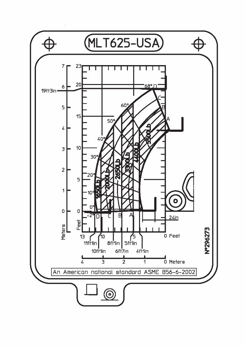

2-14
INSTRUMENTS AND CONTROLS
1
2
23
36
937
262711
30
30
5
10
34
35
33
1
3
7
12
6
156
17 16
21
4
8
15
18
22
24
25
28
157
20
19
21
22

2-15
DESCRIPTION
1 - DRIVER’S SEAT 2 - SAFETY BELT 3 - IGNITION SWITCH 4 - EMERGENCY STOP BUTTON 5 - BATTERY CUT-OFF 6 - MAN-MACHINE INTERFACE (MMI)
6A- CONTROL PANEL6B - SCREEN DISPLAY
7 - SWITCHES 8 - ARMREST AND STORAGE 9 - FUSES AND RELAYS IN THE CAB 10 - FUSES AND RELAYS UNDER THE ENGINE HOOD 11 - CIGAR LIGHTER 12 - LIGHT SWITCH, HORN AND INDICATOR SWITCH 13 - FRONT AND REAR WINDSCREEN WIPER SWITCH 14 - FUNCTION FILES 15 - HYDRAULIC CONTROLS 16 - ACCELERATOR PEDAL 17 - SERVICE BRAKE PEDAL AND TRANSMISSION CUT-OFF 18 - FORWARD/NEUTRAL/REVERSE GEAR SELECTION 19 - STEERING SELECTION 20 - HEATER CONTROL 20 - AIR CONDITIONING CONTROLS (OPTION AIR CONDITIONING) 21 - HEATING VENTS 22 - WINDSCREEN DEMISTER VENTS 23 - LEVEL INDICATOR 24 - DOOR LOCK 25 - DOOR WINDOW OPENING HANDLE 26 - DOOR WINDOW RELEASE BUTTON 27 - HANDLE FOR REAR WINDOW OPENING 28 - STEERING WHEEL ADJUSTMENT LEVER 29 - DOCUMENT HOLDER NET 30 - REAR STORAGE SPACE 31 - FRONT LIGHTS (NOT ILLUSTRATED) 32 - REAR LIGHTS (NOT ILLUSTRATED) 33 - REVOLVING LIGHT 34 - ROOF LIGHT 35 - ROOF SCREENWIPER SWITCH 36 - SUN VISOR 37 - DIAGNOSTIC CONNECTOR
NOTE: All the terms such as: RIGHT, LEFT, FRONT, REAR are meant for an observer seated on driver’s seat and looking in front of him.

1 - DRIVER’S SEAT (STANDARD)
DESIGNED FOR MAXIMUM COMFORT, THIS SEAT CAN BE ADJUSTED AS FOLLOWS.
WEIGHT ADJUSTMENT (FIG. A)Adjust the weight when the driver is sitting on the seat.- Pull the weight adjustment lever 1 fully out.- Move the weight adjustment lever 1 up to increase the weight or down to reduce it.- There are ten possible positions between the min and max weights. Before each run, return the lever to the central position. The max. or min. position is indicated by a freely travelling lever.
- The driver's weight is correctly adjusted when the jib is in the centre of indicator 2.- After completing weight adjustment, fully lower the lever 1.NOTE: To avoid any health problems, it is recommended that the weight should be checked
and adjusted before starting up the lift truck.
LONGITUDINAL ADJUSTMENT (FIG. B)- Adjust the locking lever until you reach the position required. This then locks and the seat will not shift into another position.
Only operate the lever by its recessed section and do not grasp from below, at the risk of crushingthe hand.
LUMBAR ADJUSTMENT (FIG. C)This increases the comfort of the seat and the driver’s freedom of movement.- Turn the knob to 1 to adjust the height and depth of the lumbar support of the upper part of the back-rest.
- Turn the knob to 2 to adjust the height and depth of the lumbar support of the lower part of the back-rest.
ANGLE ADJUSTMENT OF THE BACK-REST (FIG. D)- Support the back-rest, pull the lever and position the back-rest to find the desired position.
If you do not support the back-rest when making adjustments, it will swing forwards.
MAINTENANCEDirt may adversely affect the correct functioning of the seat. For this reason, make sure your seat is always clean.- The cushions do not require to be removed from the seat frame for cleaning.
A rocking head-rest increases the risk of an accident!
First check the resistance of the fabric on a small concealed area before using any fabric and plastic cleaner.
2-16
D
B
C
A
12

1 - PNEUMATIC DRIVER'S SEAT (OPTION)
DESIGNED FOR MAXIMUM COMFORT, THIS SEAT CAN BE ADJUSTED AS FOLLOWS.
WEIGHT AND SEAT HEIGHT ADJUSTMENT (FIG. A)Adjust the weight when the driver is sitting on the seat.- Switch on lift truck ignition.- Move the weight adjustment lever 1 up to increase the weight or down to reduce it.- The min and max weight can be set by engaging the upper or lower limit switch.- The driver's weight is correctly adjusted when the jib is in the centre of indicator 2.- The seat height can be adjusted within this zone.NOTE: To avoid any health problems, it is recommended that the weight should be checked
and adjusted before starting up the lift truck.
To avoid causing any damage, do not activate the compressor for over 1 minute.
LONGITUDINAL ADJUSTMENT (FIG. B)- Adjust the locking lever until you reach the position required. This then locks and the seat will not shift into another position.
Only operate the lever by its recessed section and do not grasp from below, at the risk of crushingthe hand.
LUMBAR ADJUSTMENT (FIG. C)This increases the comfort of the seat and the driver’s freedom of movement.- Turn the knob to 1 to adjust the height and depth of the lumbar support of the upper part of the back-rest.
- Turn the knob to 2 to adjust the height and depth of the lumbar support of the lower part of the back-rest.
ANGLE ADJUSTMENT OF THE BACK-REST (FIG. D)- Support the back-rest, pull the lever and position the back-rest to find the desired position.
If you do not support the back-rest when making adjustments, it will swing forwards.
MAINTENANCEDirt may adversely affect the correct functioning of the seat. For this reason, make sure your seat is always clean.- The cushions do not require to be removed from the seat frame for cleaning.
A rocking head-rest increases the risk of an accident!
First check the resistance of the fabric on a small concealed area before using any fabric and plastic cleaner.
2-17
D
B
C
A
1
2

2 - SAFETY BELT
- Sit correctly on the seat.- Check that seat belt is not twisted.- Place the seat belt at hip level.- Attach the seat belt and check that it locks.- Adjust the seat belt to your body shape without squeezing your hip and without over-slack.
In no event should the lift truck be used if the seat belt is defective (fixing, locking, cuts, tears, etc.). Repair or replace the seat belt immediately.
3 - IGNITION SWITCH
The key switch has five positions:P - Ignition off, parking position.O - Ignition switched off and I.C. engine stopped.I - Ignition on.II - Heating.III - The I.C. engine starts, return to position I as soon as the key is released.
4 - EMERGENCY STOP BUTTON
- In the event of danger, it lets you stop the I.C. Engine and thereby cut out all hydraulic movements.
- Pull the button to disable it before restarting the lift truck.
Be ready for hydraulic movements suddenly stopping when you press this button.
Warning, when driving, the lift truck will be brought to a sudden stop. If possible, stop the lift truck beforeusing the emergency stop.
5 - BATTERY CUT-OFF
- For quickly disconnecting the battery when working on the electric circuit or when soldering, for example.
6 - MAN-MACHINE INTERFACE (MMI)
6A - CONTROL PANEL6B - SCREEN DISPLAY
6A - CONTROL PANEL
A permanently lit or flashing warning lamp, with the engine running, is the sign of anoperating fault. The lighting of some lamps may be accompanied by an audible signal.Do not ignore this warning, consult your dealer without delay. If one of the warninglamps comes on while the lift truck is in motion, stop the lift truck under the safestpossible conditions.
When activating the electrical system of the lift truck, all the red and orange lamps and the panel's buzzer must light to indicate their good working order. If one of the red lamps or the buzzer does not function, carry out the necessary repairs.
2-18
RAZ
h
km/h
km/hmilesmph
pm
°C°F
V
%
am rpm
rpm
milesmph

REV COUNTER10 level leds display from 0 to 3,000 rpm.
I.C. ENGINE WATER TEMPERATURETemperature zones:
1 led - (< 40 °C) 104 °F zone. Use the lift truck with moderation, wait for temperature to increase before normal operation.2 leds - (40 °C - 60 °C) 104 °F - 140 °F zone.3 leds - (60 °C - 80 °C) 140 °F - 176 °F zone.4 leds - (80 °C - 85 °C) 176 °F - 185 °F zone.5 leds - (85 °C - 90 °C) 185 °F - 194 °F zone.6 leds - (90 °C - 95 °C) 194 °F - 203 °F -zone from 40 °C to 95 °C (140 °F - 203 °F) use the lift truck normally.7 leds - (95 °C - 105 °C) 203 °F - 221 °F zone. Use the lift truck with moderation.8 leds - (105 °C - 110 °C) 221 °F - 230 °F zone. Use the lift truck with moderation, ventilation control operating at full speed.9 leds - Red zone (110 °C - 115 °C) 230 °F - 239 °F.10 leds - Red zone (> 115 °C) > 239 °F Stop the lift truck, seek the cause of overheating.
NOTE: The red lamp and the buzzer come on (> 110 °C) 230 °F when the lift truck is running, stop the I.C. engine immediately and seek the cause of the failure in the cooling system.
FUEL LEVEL
When only one led remains displayed, the orange indicator lamp comes on, indicating that you using the reserve fuel supply and that your operating time is limited.
FORWARD/NEUTRAL/REVERSE LIGHTSee: 2 - DESCRIPTION: 19 - FORWARD/NEUTRAL/REVERSE GEAR SELECTION.
RED PARKING BRAKE LAMPThis lamp comes on when the parking brake is applied (see: 2 - DESCRIPTION: 8 - SWITCHES).
RED BRAKING OIL LEVEL LAMPIf the lamp comes on, when the lift truck is running, stop the I.C. engine immediately and check the braking oil level. In the event of an abnormal drop in the level, consult your dealer.
RED GENERAL FAULT WARNING INDICATOR LIGHTIf the lamp and the buzzer come on when the lift truck is running, stop the I.C. engine immediately and consult your dealer.
ORANGE TRANSMISSION OIL TEMPERATURE WARNING INDICATOR LIGHTThe lamp and the buzzer come on when the transmission oil temperature is abnormally high. Stop the lift truck and look for the cause of this overheating.
ORANGE HYDRAULIC OIL FILTER CLOGGING LAMP WARNING INDICATOR LIGHTThe lamp and buzzer come on when the air filter cartridge or the hydraulic return oil filter cartridge is clogged up. Stop the lift truck and carry out the necessary repairs (see cleaning and replacement requirements in chapter: 3 - MAINTENANCE: FILTERS CARTRIDGES AND BELTS).
RED I.C. ENGINE OIL PRESSURE WARNING INDICATOR LIGHTIf the lamp and the buzzer come on when the lift truck is running, stop the I.C. engine immediately and look for the cause (see oil level in I.C. engine crankcase).
ORANGE AIR FILTER CLOGGING INDICATOR LAMPThe lamp and buzzer come on when the air filter cartridge is clogged up. When this lamp comes on, the cartridge needs changing. Stop the lift truck and carry out the necessary repairs (see cleaning and replacement intervals in chapter: 3 - MAINTENANCE: FILTERS CARTRIDGES AND BELTS: SERVICING SCHEDULE).
ORANGE I.C. ENGINE PREHEATING INDICATOR LIGHTIf preheating is required, the lamp comes on when the lift truck's ignition is switched on and should go out as soon as pre-heating is ended. If this lamp comes on while the lift truck is in operation, immediately stop the I.C engine and find the cause.
2-19

RED BATTERY CHARGE INDICATOR LIGHTIf the lamp and the buzzer come on when the lift truck is running, stop the I.C. engine immediately and look for the cause (electric circuit, alternator belt, alternator, etc.).
GREEN DIRECTION INDICATOR LAMP
BLUE MAIN BEAM LAMP
6B - SCREEN DISPLAY
km/hpm
°C°F
V
%
am rpm
milesmph
UPPER SCREEN DISPLAY
h
km/hmilesmphrpm
LOWER SCREEN DISPLAY
SCROLL BUTTON
RAZVALIDATION, RESET AND ERROR CODE BUTTON
UPPER SCREEN DISPLAYSwitch on the lift truck ignition, by default, the screen will show the time. Press the scroll button to switch from one screen to the other in turn.
pmam rpm
%
km/h
mph
Clock (see adjustment). Rev counter. Attachment circuit hydraulic flow rate
(see: 16 - HYDRAULIC FLOW RATE).
Lift truck speed (see your dealer for adjustment).
Partial hour meter (see resetting).
SETTING THE TIME- Display clock screen.
- Press the button for 2 seconds, choose the "24 hour" or "12 hour am/pm" clock with the button and confirm .
- Régler les heures avec le bouton et valider .
- Set the minutes with the button and confirm .
RESETTING THE PARTIAL HOUR METER- Display the partial hour meter screen.
- Press the button for two seconds, resetting is confirmed by a beep.
LOWER SCREEN DISPLAY
Switch on the lift truck ignition, by default, the screen will show the hour meter , i.e. the total number of hours the lift truck has been used. As soon as the engine is running, the flashing pictogram records the hours of operation.
MAINTENANCE INTERVAL
NOTE: When the new lift truck is started, the maintenance key will logically be displayed to provide a reminder to replace the engine oil and the oil filter after the first 50 hours of operation (see: 3 - MAINTENANCE: SERVICING SCHEDULE).
The maintenance key appears on the hour meter screen 50 hours before the maintenance deadline and generates an audible beep.
- Press the button to display the remaining time before maintenance . In the event that the deadline is exceeded, the hours are shown with a plus sign.
2-20
RAZ
h
km/h
km/hmilesmph
pm
°C°F
V
%
am rpm
rpm
milesmph

- Press once more on the button to return to the hour meter screen. The maintenance key will be displayed for information.
- Contact your dealer to carry out the necessary maintenance operations and reset the maintenance interval.NOTE: The frequency interval displayed by default is 500 hours, this interval can be modified. Please contract your dealer.
ERROR CODES
The appearance of the maintenance key on the hour meter screen together with the sounding of an audible beep, indicate that an anomaly has been detected by one of the lift truck's Electronic Control Units (ECU).
- Press the button to display the information on the upper screen and error code .
- If there are several error codes, press the button to loop through the error codes.
- Press the button once more to return to the hour meter screen, the maintenance key remains displayed as long the as the required repairs have not been carried out.
- Contact your dealer, stating the error code or codes.NOTE: A faulty fuse can generate several error codes. When "error codes" and "maintenance interval" are displayed together,
the maintenance reminder time will appear at the end of the list.
ERROR CODE HYDROSTATIC TRANSMISSION520201 Hydraulic transmission electronic control unit voltage fault.520214 Hydraulic transmission electronic control unit fault.520215 Hydrostatic motor regulator control fault.520217 Stop light control fault.520218 Hydraulic motor speed sensor.520224 Hydrostatic motor operating solenoid valve control fault.520225 Hydraulic transmission electronic control unit fault.520226 Hydraulic transmission electronic control unit fault.520227 Hydraulic transmission electronic control unit fault.520273 Forward/reverse selector error.520274 Inching sensor error.520275 Hydrostatic pump reverse operation control fault.520276 Hydrostatic pump forward operation control fault.520277 Hydraulic pump speed sensor fault.520281 Temperature outside operating range.
ERROR CODE MAN-MACHINE INTERFACE190 Engine speed data fault.
520400 Network link fault.520401 Fuel gauge fault.520402 Engine temperature sensor fault.520404 Man-Machine Interface fault.520405 Man-Machine Interface fault.520406 Man-Machine Interface fault.520407 Man-Machine Interface fault.520408 Man-Machine Interface fault.520409 Man-Machine Interface fault.520410 Man-Machine Interface fault.520411 Man-Machine Interface fault.520412 Hydrostatic transmission network link fault.520413 Electronic handling controller network connection fault.
ERROR CODE TELESCOPE/ATTACHMENT2662 Telescope control setting fault.2663 Attachment control setting fault.
520300 Seat sensor fault.520307 Proportional telescope control fault.520310 Proportional attachment control fault.520315 Telescope control ON/OFF fault.520318 Attachment control ON/OFF fault.520336 Electronic handling controller fault.520337 Electronic handling controller fault.520338 Electronic handling controller temperature fault.520341 Attachment selector fault.520350 Proportional ventilation adjustment fault.520351 Ventilation ON/OFF adjustment control fault.520352 Attachment forced operation control fault.520362 Electronic handling controller 10V output fault.520363 Attachment forced operation indicator fault.520364 Attachment hydraulic control button fault.520365 Attachment easy hydraulic connection button.520366 Solenoid valve on jib head fault.520370 Telescope retracted sensor fault (fault detected during test).520371 Electronic handling controller temperature fault.520376 Stability indicator fault.520382 Aggravating hydraulic movement cut-off disable fault520383 Computer earth output fault.520384 Telescope retracted senor fault.520386 Jib angle sensor fault.520387 Strain gauge fault.520388 Network communication fault.520391 Inclination cut-off valve fault.520392 Angle calibration fault (fault detected during test).520393 Gauge calibration fault (fault detected during test).520394 Safety valve fault.520395 Safety valve cut-off fault (fault detected during test).520396 Lowering regulating valve fault.520397 Regulating fault (fault detected during test).520398 Raising regulating valve fault.
2-21
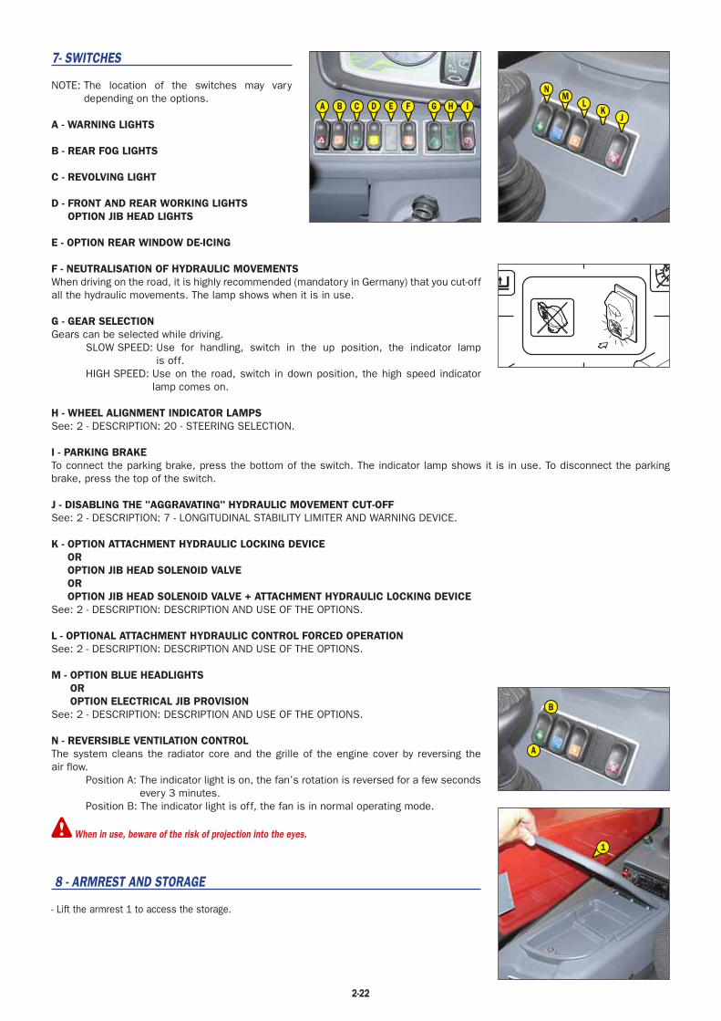
7- SWITCHES
NOTE: The location of the switches may vary depending on the options.
A - WARNING LIGHTS
B - REAR FOG LIGHTS
C - REVOLVING LIGHT
D - FRONT AND REAR WORKING LIGHTSOPTION JIB HEAD LIGHTS
E - OPTION REAR WINDOW DE-ICING
F - NEUTRALISATION OF HYDRAULIC MOVEMENTSWhen driving on the road, it is highly recommended (mandatory in Germany) that you cut-off all the hydraulic movements. The lamp shows when it is in use.
G - GEAR SELECTIONGears can be selected while driving.
SLOW SPEED: Use for handling, switch in the up position, the indicator lamp is off.
HIGH SPEED: Use on the road, switch in down position, the high speed indicator lamp comes on.
H - WHEEL ALIGNMENT INDICATOR LAMPSSee: 2 - DESCRIPTION: 20 - STEERING SELECTION.
I - PARKING BRAKETo connect the parking brake, press the bottom of the switch. The indicator lamp shows it is in use. To disconnect the parking brake, press the top of the switch.
J - DISABLING THE "AGGRAVATING" HYDRAULIC MOVEMENT CUT-OFFSee: 2 - DESCRIPTION: 7 - LONGITUDINAL STABILITY LIMITER AND WARNING DEVICE.
K - OPTION ATTACHMENT HYDRAULIC LOCKING DEVICEOROPTION JIB HEAD SOLENOID VALVEOROPTION JIB HEAD SOLENOID VALVE + ATTACHMENT HYDRAULIC LOCKING DEVICE
See: 2 - DESCRIPTION: DESCRIPTION AND USE OF THE OPTIONS.
L - OPTIONAL ATTACHMENT HYDRAULIC CONTROL FORCED OPERATIONSee: 2 - DESCRIPTION: DESCRIPTION AND USE OF THE OPTIONS.
M - OPTION BLUE HEADLIGHTSOROPTION ELECTRICAL JIB PROVISION
See: 2 - DESCRIPTION: DESCRIPTION AND USE OF THE OPTIONS.
N - REVERSIBLE VENTILATION CONTROLThe system cleans the radiator core and the grille of the engine cover by reversing the air flow.
Position A: The indicator light is on, the fan’s rotation is reversed for a few seconds every 3 minutes.
Position B: The indicator light is off, the fan is in normal operating mode.
When in use, beware of the risk of projection into the eyes.
8 - ARMREST AND STORAGE
- Lift the armrest 1 to access the storage.
2-22
A B C D E F G H IJ
KL
MN
A
B
1
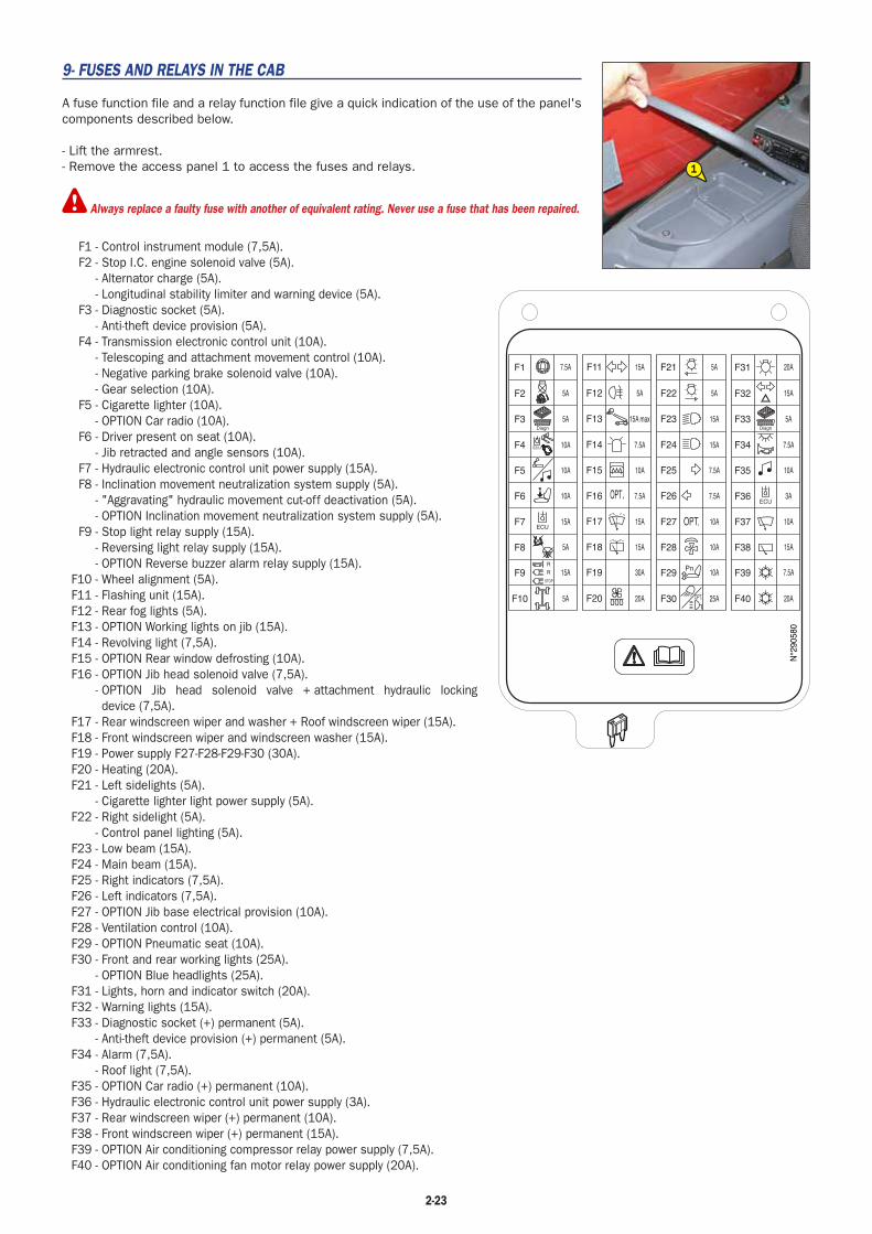
9- FUSES AND RELAYS IN THE CAB
A fuse function file and a relay function file give a quick indication of the use of the panel's components described below.
- Lift the armrest.- Remove the access panel 1 to access the fuses and relays.
Always replace a faulty fuse with another of equivalent rating. Never use a fuse that has been repaired.
F1 - Control instrument module (7,5A).F2 - Stop I.C. engine solenoid valve (5A).
- Alternator charge (5A).- Longitudinal stability limiter and warning device (5A).
F3 - Diagnostic socket (5A).- Anti-theft device provision (5A).
F4 - Transmission electronic control unit (10A).- Telescoping and attachment movement control (10A).- Negative parking brake solenoid valve (10A).- Gear selection (10A).
F5 - Cigarette lighter (10A).- OPTION Car radio (10A).
F6 - Driver present on seat (10A).- Jib retracted and angle sensors (10A).
F7 - Hydraulic electronic control unit power supply (15A).F8 - Inclination movement neutralization system supply (5A).
- "Aggravating" hydraulic movement cut-off deactivation (5A). - OPTION Inclination movement neutralization system supply (5A).
F9 - Stop light relay supply (15A).- Reversing light relay supply (15A).- OPTION Reverse buzzer alarm relay supply (15A).
F10 - Wheel alignment (5A).F11 - Flashing unit (15A).F12 - Rear fog lights (5A).F13 - OPTION Working lights on jib (15A).F14 - Revolving light (7,5A).F15 - OPTION Rear window defrosting (10A).F16 - OPTION Jib head solenoid valve (7,5A).
- OPTION Jib head solenoid valve + attachment hydraulic locking device (7,5A).
F17 - Rear windscreen wiper and washer + Roof windscreen wiper (15A).F18 - Front windscreen wiper and windscreen washer (15A).F19 - Power supply F27-F28-F29-F30 (30A).F20 - Heating (20A).F21 - Left sidelights (5A).
- Cigarette lighter light power supply (5A).F22 - Right sidelight (5A).
- Control panel lighting (5A).F23 - Low beam (15A).F24 - Main beam (15A).F25 - Right indicators (7,5A).F26 - Left indicators (7,5A).F27 - OPTION Jib base electrical provision (10A).F28 - Ventilation control (10A).F29 - OPTION Pneumatic seat (10A).F30 - Front and rear working lights (25A).
- OPTION Blue headlights (25A).F31 - Lights, horn and indicator switch (20A).F32 - Warning lights (15A).F33 - Diagnostic socket (+) permanent (5A).
- Anti-theft device provision (+) permanent (5A).F34 - Alarm (7,5A).
- Roof light (7,5A).F35 - OPTION Car radio (+) permanent (10A).F36 - Hydraulic electronic control unit power supply (3A).F37 - Rear windscreen wiper (+) permanent (10A).F38 - Front windscreen wiper (+) permanent (15A).F39 - OPTION Air conditioning compressor relay power supply (7,5A).F40 - OPTION Air conditioning fan motor relay power supply (20A).
2-23
1
N°2
9058
0
F1
F2
F3
F4
F5
F6
F7
F8
F9
F10
F37
F38
F39
F40
F29
F30
7.5A
5A
5A
10A
10A
10A
15A
5A
15A
5A
F11
F12
F13
F14
F15 10A
5A
7.5A
15A max
15A
F16 7.5A
F17
F18
F19
F20
30A
20A
15A
15A
F21
F22
F23
F24
F25
F26
7.5A
5A
15A
15A
5A
7.5A
F27
F28
10A
25A
10A
10A
F31
F32
F33
F34
F35 10A
15A
7.5A
5A
20A
F36 3A
7.5A
20A
10A
15A
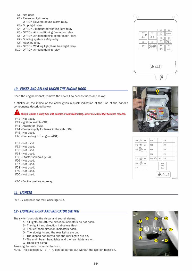
K1 - Not used.K2 - Reversing light relay.
- OPTION Reverse sound alarm relay.K3 - Stop light relay.K4 - OPTION Jib-mounted working light relayK5 - OPTION Air conditioning fan motor relay.K6 - OPTION Air conditioning compressor relay.K7 - Starting system safety relay.K8 - Flashing unit.K9 - OPTION Working light/blue headlight relay.
K10 - OPTION Air conditioning relay.
10 - FUSES AND RELAYS UNDER THE ENGINE HOOD
Open the engine bonnet, remove the cover 1 to access fuses and relays.
A sticker on the inside of the cover gives a quick indication of the use of the panel's components described below.
Always replace a faulty fuse with another of equivalent rating. Never use a fuse that has been repaired.
F41 - Not used.F42 - Ignition switch (60A).F43 - Alternator (80A).F44 - Power supply for fuses in the cab (50A).F45 - Not used.F46 - Preheating I.C. engine (40A).
F51 - Not used.F52 - Not used.F53 - Not used.F54 - Not used.F55 - Starter solenoid (20A).F56 - Not used.F57 - Not used.F58 - Not used.F59 - Not used.F60 - Not used.
K20 - Engine preheating relay.
11 - LIGHTER
For 12 V appliance and max. amperage 10A.
12 - LIGHTING, HORN AND INDICATOR SWITCH
The switch controls the visual and sound alarms.A - All lights are off, the direction indicators do not flash.B - The right hand direction indicators flash.C - The left hand direction indicators flash.D - The sidelights and the rear lights are on.E - The dipped headlights and the rear lights are on.F - The main beam headlights and the rear lights are on.G - Headlight signal.
Pressing the switch sounds the horn.NOTE: The positions D - E - F - G can be carried out without the ignition being on.
2-24
CAB
OPT.
K20
F56
F57
F58
F59
F60F55
F54
F53
F52
F51
F44
F46
F45
F43
F42
F41
40A
20A
50A
80A
60A
20A
N° 286287
B
C
A
F E G
G
G
D
A
1
N°2
9057
1
K10
K9
K8
K5
K4
K3
K2
K1
K7
OPT.STOP
RR
OPT.
K6OPT.
A.S.OPT.
OPT.

13 - FRONT AND REAR WINDSCREEN WIPER SWITCH
FRONT WINDSCREEN WIPERA - Front windscreen wiper stop.B - Slow speed for front windscreen wiper.C - Fast speed for front windscreen wiper.D - Front windscreen wiper intermittent control.E - Front windscreen washer, pulse-driven.
REAR WINDSCREEN WIPERF - Rear windscreen wiper stop.G - Rear windscreen wiper.H - Rear windscreen washer, pulse-driven.
14 - FUNCTION FILES
These files contain, among other things, the description of the hydraulic controls and the load charts for the attachments used on the lift truck.
15 - HYDRAULIC CONTROLSDo not attempt to alter the hydraulic system pressure by interfering with the pressure regulatingvalve. In the event of suspected malfunction, contact your dealer. ANY ALTERATION MAY RENDER THEWARRANTY NUL AND VOID.
Use the hydraulic controls carefully without jerking, to avoid accidents caused by shaking thelift truck.
NOTE: When driving on the road, it is highly recommended (mandatory in Germany) that you cut-off all the hydraulic movements (see: 2 - DESCRIPTION 8 - SWITCHES).
A - Lifting and tilting control lever.B - Telescoping control button.C - Attachment control button.
LIFTING THE LOAD- The lever A backwards when lifting.- The lever A forwards when lowering.
TILT OF CARRIAGE- The lever A to the left for reverse tilt.- The lever A to the right for forward tilt.
TELESCOPING- Button B forwards for extending.- Button B backwards for retracting.
ATTACHMENT- Button C forwards or backwards.
ADJUSTMENT OF ATTACHMENT HYDRAULIC FLOW RATE- Switch on lift truck ignition.
- Select the attachment circuit hydraulic flow rate screen%
with the scroll
button . The screen displays, in turn, the hydraulic flow rate stored in the memory of circuit B (without "-" sign) and of circuit A (with "-" sign).
- Press the button for two seconds, the screen will appear on the lower screen display.
- Turn button C forward to select a hydraulic flow rate for circuit B of between 10 % and 100 %.
- Hold button C at the desired flow rate and confirm with the button .
- The screen appears on the lower screen display.- Turn button C backwards to select a hydraulic flow rate for circuit A between -10 % and -100 %.
- Hold button C at the desired flow rate and confirm with the button .
- The hour meter screen appears on the lower display screen, confirming that adjustment is completed.
2-25
B
A
C
E
E
E
A
D
C
F
G
H
A
BC
N°2
6277
C

16 - ACCELERATOR PEDAL
17 - SERVICE BRAKE PEDAL AND TRANSMISSION CUT-OFF
The pedal acts on the front wheels by means of a hydraulic brake system enabling the slowing down and stopping of the lift truck. During clearance travel it enables the transmission to be cut off progressively thus allowing a gradual approach (delicate handling) with all the I.C. engine power.
18 - FORWARD/NEUTRAL/REVERSE GEAR SELECTION
When operating this control, the lift truck should be travelling at slow speed and not accelerating.
FORWARD: Push the knob forward (position A).REVERSE: Pull the knob backward (position B). An OPTIONAL reversing light and audible
reversing alarm indicate that the lift truck is travelling in reverse.
NEUTRAL: If indicators or are flashing, pass the forward/reverse selector back through neutral (position C).
SAFETY FOR MOVING THE LIFT TRUCKAuthorisation to move the lift truck is controlled by an electronic unit. The operator must observe the following sequence to move the truck forwards or backwards:
1 - sit down correctly in the driver’s seat,2 - release the parking brake,3 - engage forward or reverse.
To stop the lift truck, he must observe the following sequence:1 - set the forward/reverse selector to neutral,2 - engage the parking brake,3 - get out of the lift truck.
- If the operator leaves the driving cab with forward or reverse engaged, the screen will appear and beep will sound for two seconds. During this time, the operator can sit back down in the seat and continue advancing or reversing. When this time
is exceeded, the forward/reverse selector will switch to neutral and the indicators or will flash. The operator must sit back down and pass the forward/reverse selector back through neutral.
19 - STEERING SELECTION
A - GREEN WHEEL ALIGNMENT LAMPSThese lamps come on to indicate the alignment of the wheels in relation to the lift truck. Lamp A1 for the front wheels and lamp A2 for the rear wheels.
Before selecting one of the three possible steering positions, bring all 4 wheels into alignment withregards to the lift truck axle. Never change the steering mode whilst driving.
B - STEERING SELECTION LEVER
B1 - Front drive wheels (highway traffic).
B2 - Front and rear drive wheels in opposite direction (short steering lock).
B3 - Front and rear drive wheels in the same direction (crab steering).
CONTROL FOR ALIGNMENT OF THE WHEELS.- Shift the steering selection lever B into position B2 (short steering lock).- Turn the steering wheel and bring the rear wheels into alignment until lamp A2 lights up.- Shift the steering selection lever B into position B1 (highway traffic).- Turn the steering wheel and bring the front wheels into alignment until lamp A1 lights up.
Before driving on roads, it is necessary to check the alignment of the rear wheels and to drive in frontwheel steer. The control of the alignment of the rear wheels must be regularly done with the help of thegreen lamps, while driving the lift truck. In case of anomalies, consult your dealer.
2-26
B3
B2
B1
A
C B
A2
A1

2-27
20 - HEATER CONTROL
A - FAN CONTROLThis 3-speed control allows the air to be ventilated through the air vents.
B - TEMPERATURE CONTROLAllows the temperature inside the cab to be adjusted.
B1 - The fan pumps in the air at ambient temperature.B2 - The fan pumps in warm air.
The intermediate positions allow the temperature to be adjusted.
20 - AIR CONDITIONING CONTROLS (OPTION AIR CONDITIONING)
The air conditioning only works if the lift truck has been started up. When using your air conditioningunit you must work with the cab closed off. In winter: So as to ensure correct operation and complete efficiency of the air conditioning unit,start up the compressor once a week, if only for a short spell, so as to lubricate the internal seals. In cold weather: Warm the I.C. engine before switching on the compressor, so as to allow thecoolant that has collected in a liquid state at the lowest point of the compressor circuit to turn intogas under the effect of the heat given off by the I.C. engine, as the compressor is liable to be damagedby coolant in a liquid state.
If your air conditioning does not seem to be working correctly, have it examined by your dealer (see: 3- MAINTENANCE: F - EVERY 2000 HOURS OF SERVICE). Never try to repair any faults yourself.
A - FAN CONTROLThis 3-speed control allows the air to be ventilated through the air vents.
B - TEMPERATURE CONTROLAllows the temperature inside the cab to be adjusted.
B1 - The fan pumps in cold air.B2 - The fan pumps in warm air.
The intermediate positions allow the temperature to be adjusted.
C - AIR CONDITIONING CONTROLThis control with a pilot light allows the air conditioning unit to be switched on.
HEATING MODEThe controls must be adjusted in the following way:
C - Control with pilot light off.B - At the required temperature.A - At the desired speed: 1, 2 or 3.
CONDITIONED AIR MODEThe controls must be adjusted in the following way:
C - Control with pilot light on.B - At the required temperature.A - At the desired speed: 1, 2 or 3.
DEMISTING MODEThe controls must be adjusted in the following way:
C - Control with pilot light on.B - At the required temperature.A - At speed 3.
For optimum effectiveness, close the heating ventilators.
A
B1 B2
B
C
A
B1 B2
B

2-28
21 - HEATING VENTS
These swivelling heating vents, which can be shut off, allow you to direct and adjust the flow rate inside the cab.
22 - DEMIST VENTS
These vents allow the front windscreen and side windows to be demisted. For optimum efficiency, shut off the heating vents.
23 - LEVEL INDICATOR
Enables the operator to check that the lift truck is in the horizontal position.
24 - DOOR LOCK
Two keys are provided with the lift truck to enable the cabin to be locked.
25 - DOOR WINDOW OPENING HANDLE
26 - DOOR WINDOW RELEASE BUTTON
27 - HANDLE FOR REAR WINDOW OPENING
EMERGENCY EXITUse the rear window as an emergency exit, if it is impossible to leave the cab by the door.
28 - STEERING WHEEL ADJUSTMENT LEVER
This handle enables the angle and height of the steering wheel to be adjusted.
- Pull the knob 1 backwards.- Adjust the steering wheel to the desired position.- Push the knob back to lock the steering wheel in position.
29 - DOCUMENT HOLDER NET
Make sure that the operator’s manual is in the right place, i.e. in the document holder net.NOTE: An OPTION waterproof document-holder exists.
30 - REAR STORAGE SPACE
1
24
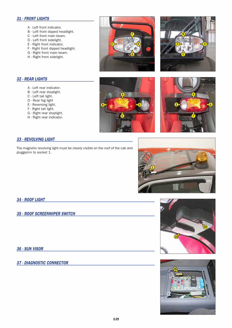
2-29
31 - FRONT LIGHTS
A - Left front indicator.B - Left front dipped headlight.C - Left front main beam.D - Left front sidelight.E - Right front indicator.F - Right front dipped headlight.G - Right front main beam.H - Right front sidelight.
32 - REAR LIGHTS
A - Left rear indicator.B - Left rear stoplight.C - Left tail light.D - Rear fog lightE - Reversing light.F - Right tail light.G - Right rear stoplight.H - Right rear indicator.
33 - REVOLVING LIGHT
The magnetic revolving light must be clearly visible on the roof of the cab and plugged-in to socket 1.
34 - ROOF LIGHT
35 - ROOF SCREENWIPER SWITCH
36 - SUN VISOR
37 - DIAGNOSTIC CONNECTOR
H
E G
F
A
B D
C
B
A
C
D
F
H
G
E
1
35
36
38

TOWING PIN AND HOOK
Located at the rear of the lift truck, this device is used to attach a trailer. Its capacity is limited for each lift truck by the authorised gross vehicle weight, tractive effort and maximum vertical force on the coupling point. This information is given on the manufacturer's plate fixed to each lift truck (see: 2 - DESCRIPTION: IDENTIFICATION OF THE LIFT TRUCK).
- To use a trailer, see current regulations in your country (maximum running speed, braking, maximum weight of trailer, etc.).- Verify the trailer's condition before using it (tyre condition and pressures, electrical connection, hydraulic hose, brake system…).
Do not tow a trailer or attachment which is not in perfect working order. Using a trailer in poor condition may affect the lift truck's steering and braking,and hence safety.
If a third party helps in coupling or uncoupling the trailer, this person must be permanently visible to the driver and wait until the lift truck has stopped,the handbrake is on and the I.C. engine is switched off before performing the operation.
NOTE: There is an OPTIONAL rear-view mirror which allows the lift truck to be approached more closely to the trailer ring.
A - TOWING PIN
COUPLING AND UNCOUPLING THE TRAILER- To couple the trailer, position the lift truck as close as possible to the trailer ring.- Switch off the I.C. engine.- Remove the clip 1, lift the trailer pin 2 and place or remove the trailer ring.
Be careful not to get your fingers caught or crushed during this operation. Do not forget to put clip 1back in place. When uncoupling, make sure that the trailer is supported independently.
B - REAR ELECTRIC SOCKET
- Connect the male plug to the female socket 1 on the lift truck and make sure the lights of the trailer or the light bar are working properly.
A - Left rear indicator.B - Rear fog lights.C - Earth.D - Right rear indicator.E - Right tail light.F - Rear stop light.G - Left rear light and number plate.
C - COUPLING FITTING (OPTION)
COUPLING AND UNCOUPLING THE TRAILER- To couple the trailer, position the lift truck as close as possible to the trailer ring.- Switch off the I.C. engine.- Remove the clip 1, lift the trailer pin 2 and place or remove the trailer ring.
Be careful not to get your fingers caught or crushed during this operation. Do not forget to put clip 1back in place. When uncoupling, make sure that the trailer is supported independently.
2-30
1
2
A
G
C
B
D
E
F
1
1
2

2-31

DESCRIPTION AND USE OF THE OPTIONS
1- PREHEATING ELEMENT
Enables the engine block to be kept warm during prolonged periods of stoppage and thus improves engine starting.
SUPPLY CHARACTERISTICS OF PREHEATING SYSTEM:• Rated range of power: 220-240V ; 50-60Hz• Current consumption: 4,5A• Class 1 equipment• Equipment connectable only to Earth-Earth (TT) or Earth-Neutral (TN) circuits• Installation category 2
ENVIRONMENTAL CONDITIONS FOR USE:• Maximum ambient temperature for using preheating: +25°C (77°F)• Pollution level 2
CONDITIONS FOR CONNECTION AND USE OF PREHEATING:- The preheating system should not be used for an external ambient temperature higher than + 25°C (77°F).- It is essential that the power supply to the preheating system is:
• Effected with a cable that conforms to the installation standards in force and contains a protective earth conductor.• Contains an appropriate isolation system.• Incorporate an appropriate safety system against short circuits (fuses or circuit breaker) and a differential circuit breaker
with 30 mA sensitivity.- Only connect to and disconnect from the power supply while the unit is off and the I.C. engine is stopped.
2 - REVERSE BUZZER ALARM
3 - NUMBER PLATE LIGHTING
4 - ANGULAR SECTOR ON JIB
The angular sector displays the jib angle, and thus improves the reading of the load charts.
2-32
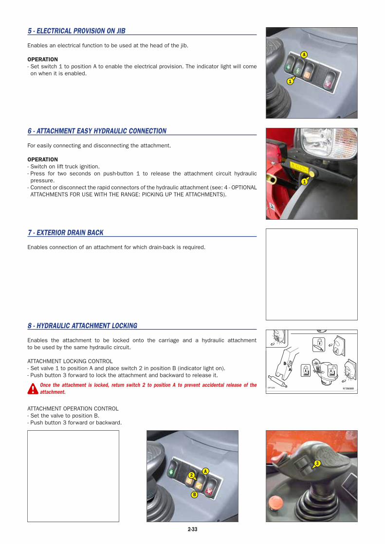
5 - ELECTRICAL PROVISION ON JIB
Enables an electrical function to be used at the head of the jib.
OPERATION- Set switch 1 to position A to enable the electrical provision. The indicator light will come on when it is enabled.
6 - ATTACHMENT EASY HYDRAULIC CONNECTION
For easily connecting and disconnecting the attachment.
OPERATION- Switch on lift truck ignition.- Press for two seconds on push-button 1 to release the attachment circuit hydraulic pressure.
- Connect or disconnect the rapid connectors of the hydraulic attachment (see: 4 - OPTIONAL ATTACHMENTS FOR USE WITH THE RANGE: PICKING UP THE ATTACHMENTS).
7 - EXTERIOR DRAIN BACK
Enables connection of an attachment for which drain-back is required.
8 - HYDRAULIC ATTACHMENT LOCKING
Enables the attachment to be locked onto the carriage and a hydraulic attachment to be used by the same hydraulic circuit.
ATTACHMENT LOCKING CONTROL- Set valve 1 to position A and place switch 2 in position B (indicator light on).- Push button 3 forward to lock the attachment and backward to release it.
Once the attachment is locked, return switch 2 to position A to prevent accidental release of theattachment.
ATTACHMENT OPERATION CONTROL- Set the valve to position B.- Push button 3 forward or backward.
2-33
1
A
2
B
A
3
N°286989
1

9 - JIB HEAD SOLENOID VALVE
Enables use of two hydraulic functions on the attachment circuit.
To make connection of the rapid connectors easier, decompress the hydraulic circuit by pressing button 1on the solenoid valve.
ATTACHMENT LINE A1/B1 CONTROL- Set switch 1 to position A (indicator light off).- Push button 2 forward or backward.
ATTACHMENT LINE A2/B2 CONTROL- Set switch 1 to position B (indicator light on) and hold down button 3.- Push button 2 forward or backward.
10 - JIB HEAD SOLENOID VALVE + HYDRAULIC ATTACHMENT LOCKING
Enables the use of a hydraulic function and hydraulic locking of the attachment on the attachment circuit.
To make connection of the rapid connectors easier, decompress the hydraulic circuit by pressing button 1on the solenoid valve.
ATTACHMENT LINE A1/B1 CONTROL- Set switch 1 to position A (indicator light off).- Push button 2 forward or backward.
ATTACHMENT A2/B2 LOCKING CONTROL- Set switch 1 to position B (indicator light on) and hold down button 3.- Push button 2 forward to lock the attachment and backward to release it.
2-34
N°2
9043
9
A1B1
A2B2
A1
B1
A2
B2
N°2
9043
9
A1B1
A2B2
A1
B1
A2
B2
1
B
A
1
3
2
1
B
A
1
3
2
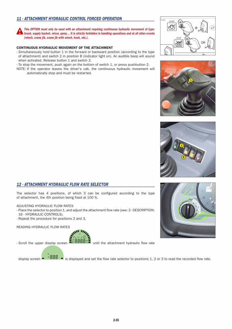
11 - ATTACHMENT HYDRAULIC CONTROL FORCED OPERATION
This OPTION must only be used with an attachment requiring continuous hydraulic movement of type:brush, supply bucket, mixer, spray… It is strictly forbidden in handling operations and at all other events(winch, crane jib, crane jib with winch, hook, etc.).
CONTINUOUS HYDRAULIC MOVEMENT OF THE ATTACHMENT- Simultaneously hold button 1 in the forward or backward position (according to the type of attachment) and switch 2 in position B (indicator light on). An audible beep will sound when activated. Release button 1 and switch 2.
- To stop the movement, push again on the bottom of switch 1, or press pushbutton 2.NOTE: If the operator leaves the driver's cab, the continuous hydraulic movement will
automatically stop and must be restarted.
12 - ATTACHMENT HYDRAULIC FLOW RATE SELECTOR
The selector has 4 positions, of which 3 can be configured according to the type of attachment, the 4th position being fixed at 100 %.
ADJUSTING HYDRAULIC FLOW RATES- Place the selector to position 1, and adjust the attachment flow rate (see: 2 - DESCRIPTION: 16 - HYDRAULIC CONTROLS).
- Repeat the procedure for positions 2 and 3.
READING HYDRAULIC FLOW RATES
- Scroll the upper display screen km/hpm
°C°F
V
%
am rpm
milesmph
until the attachment hydraulic flow rate
display screen
%
is displayed and set the flow rate selector to positions 1, 2 or 3 to read the recorded flow rate.
2-35
1
2
B

2-36

3-1
3 - MAINTENANCE

3-2
3-3
TABLE OF CONTENTS
MANITOU ORIGINAL SPARE PARTS AND EQUIPMENT 3-4
START-UP CHECKLIST 3-5
FILTERS CARTRIDGES AND BELTS 3-6
LUBRICANTS AND FUEL 3-8
SERVICING SCHEDULE 3-10
A - DAILY OR EVERY 10 HOURS SERVICE 3-12
B - EVERY 50 HOURS SERVICE 3-16
C - EVERY 250 HOURS OF SERVICE 3-20
D - EVERY 500 HOURS SERVICE 3-22
E - EVERY 1000 HOURS OF SERVICE 3-26
F - EVERY 2000 HOURS OF SERVICE 3-30
G - OCCASIONAL MAINTENANCE 3-32

3-4
MANITOU ORIGINAL SPARE PARTS AND EQUIPMENT
OUR LIFT TRUCKS MUST BE SERVICED USING ORIGINAL MANITOU PARTS.
IF YOU USE PARTS WHICH ARE NOT ORIGINAL MANITOU PARTS,
YOU RISK - Legally - to be held responsible in the event of an accident.
- Technically - to generate operating failure or shorten the life of the lift truck.
THE USE OF COUNTERFEIT PARTS OR COMPONENTS NOT APPROVED BY THE MANUFACTURER,MEANS YOU LOSE THE BENEFIT OF THE CONTRACTUAL GUARANTEE.
BY USING ORIGINAL MANITOU PARTS FOR MAINTENANCE OPERATIONS,
YOU BENEFIT Through its network, MANITOU provides the user withEXPERTISE - Know-how and competence.
- The guarantee of high-quality work.
- Original replacement components.
- Help with preventive maintenance.
- Efficient help with diagnosis.
- Improvements due to experience feedback.
- Operator training.
- Only the MANITOU network has detailed knowledge of the design of the lift truck and therefore the best technical ability to provide maintenance.
ORIGINAL REPLACEMENT PARTS ARE DISTRIBUTED EXCLUSIVELY BY MANITOU AND ITS DEALER NETWORK.the dealer network list is available on manitou web site www.manitou.com

3-5
START-UP CHECKLIST0 = OK 1 = Missing 2 = Incorrect
100 ENGINE
01 Air filter
02 Fuel tank
03 Fuel lines - Filter
04 Injection or carburetion system
05 Radiator and cooling system
06 Belts
07 Hoses
101 TRANSMISSION
01 Direction reversal system
02 Gear shift
03 Cut-off pedal
04 Clutch
102 AXLES/TRANSFER GEAR BOX
01 operation and seal
02 Stop settings
103 HYDRAULIC/HYDROSTATIC CIRCUIT
01 Tank
02 Pumps and couplings
03 Tightening of connections
04 Lift cylinder(s)
05 Tilt cylinder(s)
06 Attachment cylinder(s)
07 Telescope cylinder(s)
08 Compensation cylinder(s)
09 Steering cylinder(s)
10 Control Valve
11 Balancing valve
104 BRAKE SYSTEM
01 Service brake and parking brake operation
02 Brake fluid level
105 LUBRICATION AND GREASING
106 JIB/MANISCOPIC/MANIACCESS ASSEMBLY
01 Beam and telescope(s)
02 Skid
03 Hinges
04 Carriage
05 Forks
107 MAST ASSEMBLY
01 Fixed and mobile uprights
02 Carriage
03 Chains
04 Rollers
05 Forks
108 ATTACHMENTS
01 Fitting on machine
02 Hydraulic couplings
109 CABIN/PROTECTOR/ELECTRIC CIRCUIT
01 Seat
02 Dashboard and radio
03 Sound and visual alarm/safety system
04 Heating/Air conditioning
05 Windscreen wiper/windscreen washer
06 Road horn
07 Reversing horn
08 Road lights
09 Additional lights
10 Rotating beacon light
11 Battery
110 WHEEL
01 Rims
02 Tyre/Pressure
111 SCREWS
112 FRAME AND BODYWORK
113 PAINTING
114 GENERAL OPERATION
115 OPERATOR’S MANUAL
116 CUSTOMER INSTRUCTIONS

3-6
FILTERS CARTRIDGES AND BELTS
HYDRAULIC
HYDRAULIC RETURN OIL FILTER CARTRIDGEPart number: 686236Change : 500 H
BRAKE ACCUMULATOR UNIT FILTERPart number: 746308Change : 1000 H
CAB
CAB VENTILATION FILTERSPart number: 750306Clean: 50 HChange: 250 H
I.C. ENGINE
I.C. ENGINE OIL FILTERPart number: 279809Change: 500 H
ALTERNATOR BELTPart number: 292198
DRY AIR FILTER CARTRIDGEPart number: 563416Clean: 50 H*Change: 500 H*
VENTILATION ADJUSTMENT BELTPart number: 289330
SAFETY DRY AIR FILTER CARTRIDGEPart number: 563415Change: 1000 H*
WATER PUMP KITPart number: 894164Change: 3000 H
FUEL FILTERPart number: 746364Change: 500 H
CYCLONIC PRE-FILTERPart number: 224713Clean: 10 H
*: This frequency is given for information only (see: 3 - MAINTENANCE: SERVICING SCHEDULE) for cleaning and changing.

3-7
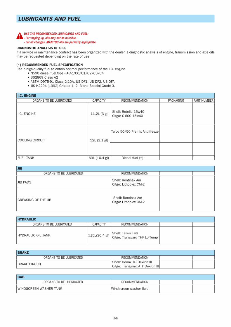
3-8
LUBRICANTS AND FUEL
USE THE RECOMMENDED LUBRICANTS AND FUEL:- For topping up, oils may not be miscible.- For oil changes, MANITOU oils are perfectly appropriate.
DIAGNOSTIC ANALYSIS OF OILSIf a service or maintenance contract has been organized with the dealer, a diagnostic analysis of engine, transmission and axle oils may be requested depending on the rate of use.
(*) RECOMMENDED FUEL SPECIFICATIONUse a high-quality fuel to obtain optimal performance of the I.C. engine.
• N590 diesel fuel type - Auto/C0/C1/C2/C3/C4• BS2869 Class A2• ASTM D975-91 Class 2-2DA, US DF1, US DF2, US DFA• JIS K2204 (1992) Grades 1, 2, 3 and Special Grade 3.
I.C. ENGINEORGANS TO BE LUBRICATED CAPACITY RECOMMENDATION PACKAGING PART NUMBER
I.C. ENGINE 11,2L (3 gl) Shell: Rotella 15w40 Citgo: C-600 15w40
COOLING CIRCUIT 12L (3.1 gl)
Tulco 50/50 Premix Anti-freeze
FUEL TANK 63L (16.4 gl) Diesel fuel (*)
JIBORGANS TO BE LUBRICATED RECOMMENDATION
JIB PADS Shell: Rentinax Am Citgo: Lithoplex CM-2
GREASING OF THE JIB Shell: Rentinax Am Citgo: Lithoplex CM-2
HYDRAULICORGANS TO BE LUBRICATED CAPACITY RECOMMENDATION
HYDRAULIC OIL TANK 115L(30.4 gl) Shell: Tellus T46 Citgo: Transgard THF Lo-Temp
BRAKEORGANS TO BE LUBRICATED RECOMMENDATION
BRAKE CIRCUIT Shell: Donax TG Dexron III Citgo: Transgard ATF Dexron III
CABORGANS TO BE LUBRICATED RECOMMENDATION
WINDSCREEN WASHER TANK Windscreen washer fluid

3-9
REAR AXLEORGANS TO BE LUBRICATED CAPACITY RECOMMENDATION
REAR AXLE DIFFERENTIAL 3,8L (1 gl) Shell: Donax TD Citgo: Transgard (THF)
REAR WHEELS REDUCERS 0,9L (.95 qt) Shell: Spirax DH 80w90 Citgo:Premium Gear MP 80w90
REAR WHEELS REDUCERS PIVOTSREAR AXLE OSCILLATION
Shell: Rentinax Am Citgo: Lithoplex CM-2
FRONT AXLEORGANS TO BE LUBRICATED CAPACITY RECOMMENDATION
FRONT AXLE DIFFERENTIAL 4L (1 gl) Shell: Donax TD Citgo: Transgard (THF)
TRANSFER BOX
FRONT WHEELS REDUCERS
,75L (.8 qt)
,8L (.85 qt)
Shell: Spirax DH 80w90 Citgo: Premium Gear MP 80w90
FRONT WHEELS REDUCERS PIVOTS Shell: Rentinax Am Citgo: Lithoplex CM-2
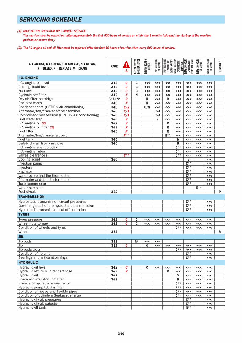
3-10
SERVICING SCHEDULE
(1): MANDATORY 500 HOUR OR 6 MONTH SERVICEThis service must be carried out after approximately the first 500 hours of service or within the 6 months following the start-up of the machine(whichever occurs first).
(2): The I.C engine oil and oil filter must be replaced after the first 50 hours of service, then every 500 hours of service.
A = ADJUST, C = CHECK, G = GREASE, N = CLEAN,P = BLEED, R = REPLACE, V = DRAIN PAGE
(1)
DAILY
OR EV
ERY 1
0 HO
URS O
F SER
VICE
EVERY
50 HO
URS O
F SER
VICE
EVERY
250 H
OURS
OF
SERV
ICE
EVERY
500 H
OURS
OF
SERV
ICE OR
EVE
RY 6
MONT
HSEVE
RY 10
00 HO
URS
OF SE
RVICE
OR
EVERY
YEAR
EVERY
2000
HOUR
S OF
SERV
ICE OR
EVE
RY TW
O YEA
RS
EVERY
3000
HOUR
S OF
SERV
ICE
EVERY
4000
HOUR
S OF
SERV
ICE
OCCA
SIONA
LLY
I.C. ENGINEI.C. engine oil level 3-12 C C <<< <<< <<< <<< <<< <<< <<<Cooling liquid level 3-12 C C <<< <<< <<< <<< <<< <<< <<<Fuel level 3-12 C C <<< <<< <<< <<< <<< <<< <<<Cyclonic pre-filter 3-12 N N <<< <<< <<< <<< <<< <<< <<<Dry air filter cartridge 3-16/22 R N <<< R <<< <<< <<< <<<Radiator cores 3-16 N N <<< <<< <<< <<< <<< <<<Condenser core (OPTION Air conditioning) 3-16 C/N C/N <<< <<< <<< <<< <<< <<<Alternator/fan/crankshaft belt tension 3-20 C/A C/A <<< <<< <<< <<< <<<Compressor belt tension (OPTION Air conditioning) 3-20 C/A C/A <<< <<< <<< <<< <<<Fuel water trap 3-20 V V <<< <<< <<< <<< <<<I.C. engine oil (2) 3-22 V V <<< <<< <<< <<<I.C. engine oil filter (2) 3-22 R R <<< <<< <<< <<<Fuel filter 3-23 R R <<< <<< <<< <<<Alternator/fan/crankshaft belt R** R** <<< <<< <<< <<<Fuel tank 3-26 N <<< <<< <<<Safety dry air filter cartridge 3-26 R <<< <<< <<<I.C. engine silent blocks C** <<< <<< <<<I.C. engine rates C** <<< <<< <<<Valves clearances C** C** <<< <<< <<<Cooling liquid 3-30 V <<<Injection pump C** <<<Injectors C** <<<Radiator C** <<<Water pump and the thermostat C** <<<Alternator and the starter motor C** <<<Turbocompressor C** <<<Water pump kit R**Fuel circuit 3-32 PTRANSMISSIONHydrostatic transmission circuit pressures C** <<<Governing start of the hydrostatic transmission C** <<<Hydrostatic transmission cut-off operation C** <<<TYRESTyres pressure 3-13 C C <<< <<< <<< <<< <<< <<< <<<Wheel nuts torque 3-13 C C <<< <<< <<< <<< <<< <<< <<<Condition of wheels and tyres C** <<< <<< <<<Wheel 3-32 RJIBJib pads 3-13 G* <<< <<<Jib 3-17 G G <<< <<< <<< <<< <<< <<<Jib pads wear C** <<< <<< <<<Condition of jib unit C** <<<Bearings and articulation rings C** <<<HYDRAULICHydraulic oil level 3-18 C C <<< <<< <<< <<< <<< <<<Hydraulic return oil filter cartridge 3-23 R R <<< <<< <<< <<<Hydraulic oil 3-27 V <<< <<< <<<Brake accumulator unit filter 3-27 R <<< <<< <<<Speeds of hydraulic movements C** <<< <<< <<<Hydraulic pump tubular filter N** <<< <<< <<<Condition of hoses and flexible pipes C** <<< <<< <<<Condition of cylinders (leakage, shafts) C** <<< <<< <<<Hydraulic circuit pressures C** <<<Hydraulic circuit outputs C** <<<Hydraulic oil tank N** <<<

3-11
A = ADJUST, C = CHECK, G = GREASE, N = CLEAN,P = BLEED, R = REPLACE, V = DRAIN PAGE
(1)
DAILY
OR EV
ERY 1
0 HO
URS O
F SER
VICE
EVERY
50 HO
URS O
F SER
VICE
EVERY
250 H
OURS
OF
SERV
ICE
EVERY
500 H
OURS
OF
SERV
ICE OR
EVE
RY 6
MONT
HSEVE
RY 10
00 HO
URS
OF SE
RVICE
OR
EVERY
YEAR
EVERY
2000
HOUR
S OF
SERV
ICE OR
EVE
RY TW
O YEA
RS
EVERY
3000
HOUR
S OF
SERV
ICE
EVERY
4000
HOUR
S OF
SERV
ICE
OCCA
SIONA
LLY
BRAKEBrake oil level 3-18 C C <<< <<< <<< <<< <<< <<<Brake oil V** <<< <<< <<<Brake system P** <<< <<< <<<Brake system pressure C** <<< <<< <<<Brake A** <<< <<< <<<STEERINGSteering C** <<<Steering swivel joints C**CABWindscreen washer liquid level 3-18 C C <<< <<< <<< <<< <<< <<<Cab ventilation filters 3-18/20 R N R <<< <<< <<< <<< <<<Seat belt 3-28 C <<< <<< <<<Condition of the rear view mirrors C** <<< <<< <<<Structure C** <<< <<< <<<Air conditioning (OPTION) 3-31 N/C <<<ELECTRICITYLongitudinal stability and limiter warning device 3-14/38 C C <<< <<< <<< <<< <<< <<< <<< XXXCondition of wiring harness and cables C** <<< <<< <<<Lights and signals C** <<< <<< <<<Warning indicators C** <<< <<< <<<Front headlights 3-33 ABattery failure 3-33 RFRONT AXLEFront wheels reducers pivots 3-17 G G <<< <<< <<< <<< <<< G/C**Transfer box oil level 3-21 C C <<< <<< <<< <<< <<<Front axle differential oil level 3-21 C C <<< <<< <<< <<< <<<Front wheels reducers oil level 3-21 C C <<< <<< <<< <<< <<<Transfer box oil 3-24 V V <<< <<< <<< <<<Front axle differential oil 3-24 V V <<< <<< <<< <<<Front wheels reducers oil 3-28 V V <<< <<< <<<Wear of front axle brake discs C**Front wheels reducers universal joint C**Front wheels reducers clearance C**Set of transfer box rolling bearings C**REAR AXLERear wheels reducers pivots 3-17 G G <<< <<< <<< <<< <<< G/C**Rear axle oscillation 3-17 G G <<< <<< <<< G/C** <<<Rear axle differential oil level 3-21 C C <<< <<< <<< <<< <<<Rear wheels reducers oil level 3-21 C C <<< <<< <<< <<< <<<Rear axle differential oil 3-28 V V <<< <<< <<<Rear wheels reducers oil 3-28 V V <<< <<< <<<Rear wheels reducers universal jointdifferential C**Rear wheels reducers clearance C**CHASSISStructure C** <<< <<< <<<Bearings and articulation rings C** <<<ATTACHMENTSForks wear C** C** <<< <<< <<< <<<Attachment carriage C** <<< <<< <<<Condition of attachments C** <<< <<< <<<LIFT TRUCKTow the lift truck 3-34 XXXSling the lift truck 3-34 XXXTransport the lift truck on a platform 3-35 XXX
(*): Every 10 hours of service during the first 50 hours of service, then one last time at 250 hours of service.(**): Consult your dealer.
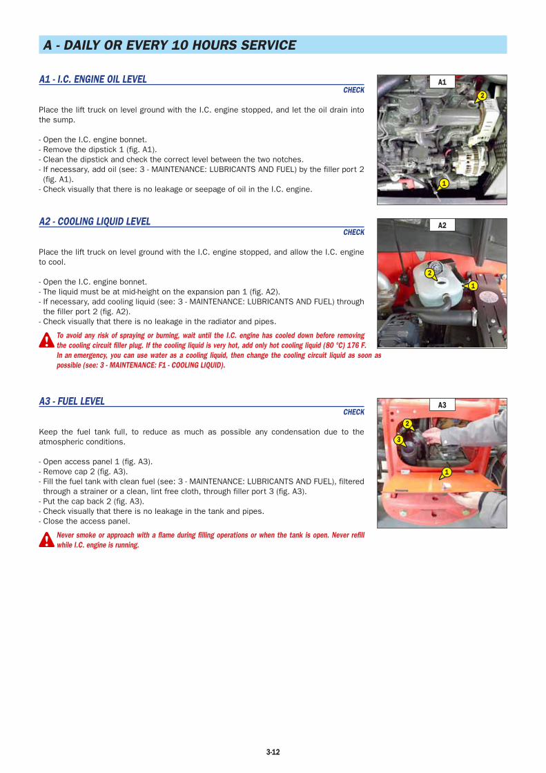
3-12
A - DAILY OR EVERY 10 HOURS SERVICE
A1 - I.C. ENGINE OIL LEVELCHECK
Place the lift truck on level ground with the I.C. engine stopped, and let the oil drain into the sump.
- Open the I.C. engine bonnet.- Remove the dipstick 1 (fig. A1).- Clean the dipstick and check the correct level between the two notches.- If necessary, add oil (see: 3 - MAINTENANCE: LUBRICANTS AND FUEL) by the filler port 2 (fig. A1).
- Check visually that there is no leakage or seepage of oil in the I.C. engine.
A2 - COOLING LIQUID LEVELCHECK
Place the lift truck on level ground with the I.C. engine stopped, and allow the I.C. engine to cool.
- Open the I.C. engine bonnet.- The liquid must be at mid-height on the expansion pan 1 (fig. A2).- If necessary, add cooling liquid (see: 3 - MAINTENANCE: LUBRICANTS AND FUEL) through the filler port 2 (fig. A2).
- Check visually that there is no leakage in the radiator and pipes.
To avoid any risk of spraying or burning, wait until the I.C. engine has cooled down before removingthe cooling circuit filler plug. If the cooling liquid is very hot, add only hot cooling liquid (80 °C) 176 F.In an emergency, you can use water as a cooling liquid, then change the cooling circuit liquid as soon aspossible (see: 3 - MAINTENANCE: F1 - COOLING LIQUID).
A3 - FUEL LEVELCHECK
Keep the fuel tank full, to reduce as much as possible any condensation due to the atmospheric conditions.
- Open access panel 1 (fig. A3).- Remove cap 2 (fig. A3).- Fill the fuel tank with clean fuel (see: 3 - MAINTENANCE: LUBRICANTS AND FUEL), filtered through a strainer or a clean, lint free cloth, through filler port 3 (fig. A3).
- Put the cap back 2 (fig. A3).- Check visually that there is no leakage in the tank and pipes.- Close the access panel.
Never smoke or approach with a flame during filling operations or when the tank is open. Never refillwhile I.C. engine is running.
A1
2
1
A2
2
1
A3
3
1
2

3-13
A4 - CYCLONIC PRE-FILTERCLEAN
The cleaning interval is given as a guide, however the pre-filter must be emptied as soon as impurities reach the MAXI level on the tank.
- Loosen nut 1 (fig. A4), remove cover 2 (fig. A4) and empty the tank.- Clean the pre-filter unit with a clean dry cloth and reassemble the unit.
When cleaning, take care not to let impurities into the dry air filter.
A5 - TYRES PRESSURE AND WHEEL NUTS TORQUECHECK
- Check the condition of the tyres, to detect cuts, protuberances, wear, etc.- Check the torque load of the wheel nuts. Non compliance with this instruction can cause damage and rupture to the wheel bolts and distortion to the wheels.
Wheel nuts tightening torque• Front tyres: 630 N.m (465 lbf/ft) ± 15%• Rear tyres: 630 N.m (465 lbf/ft) ± 15%
- Check and adjust the tyre pressures if necessary (see: 2 - DESCRIPTION: FRONT AND REAR TYRES).
Check that the air hose is correctly connected to the tyre valve before inflating and keep all persons at a distance during inflation. Respect therecommended tyre pressures given.
NOTE: There is an OPTIONAL wheel toolkit.
A6 - JIB PADSCLEAN - GREASE
To be carried out every 10 hours during the first 50 hours service, then once at 250 hours.
- Extend the jib completely.- With a brush, apply a coat of grease (see: 3 - MAINTENANCE: LUBRICANTS AND FUEL) on the 4 sides of the telescope(s) (fig. A6).
- Telescope the jib several times in order to spread the coat of grease evenly.- Remove the surplus of grease.
If the lift truck is used in an abrasive environment (dust, sand, coal…) Use lubricating varnish (MANITOUreference: 483536). In this respect, consult your dealer.
A6
A4
12

3-14
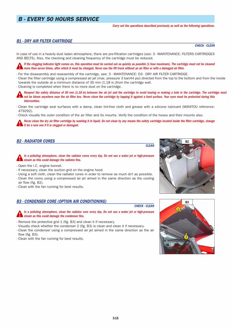
3-15
B - EVERY 50 HOURS SERVICECarry out the operations described previously as well as the following operations.
B1 - DRY AIR FILTER CARTRIDGECHECK - CLEAN
In case of use in a heavily dust laden atmosphere, there are pre-filtration cartridges (see: 3 - MAINTENANCE: FILTERS CARTRIDGES AND BELTS). Also, the checking and cleaning frequency of the cartridge must be reduced.
If the clogging indicator light comes on, this operation must be carried out as quickly as possible (1 hour maximum). The cartridge must not be cleanedmore than seven times, after which it must be changed. Never use the lift truck without an air filter or with a damaged air filter.
- For the disassembly and reassembly of the cartridge, see: 3 - MAINTENANCE: D3 - DRY AIR FILTER CARTRIDGE.- Clean the filter cartridge using a compressed air jet (max. pressure 3 bar(44 psi) directed from the top to the bottom and from the inside towards the outside at a minimum distance of 30 mm (1.18 in.)from the cartridge wall.
- Cleaning is completed when there is no more dust on the cartridge.
Respect the safety distance of 30 mm (1.18 in) between the air jet and the cartridge to avoid tearing or making a hole in the cartridge. The cartridge mustnot be blown anywhere near the air filter box. Never clean the cartridge by tapping it against a hard surface. Your eyes must be protected during thisintervention.
- Clean the cartridge seal surfaces with a damp, clean lint-free cloth and grease with a silicone lubricant (MANITOU reference: 479292).
- Check visually the outer condition of the air filter and its mounts. Verify the condition of the hoses and their mounts also.
Never clean the dry air filter cartridge by washing it in liquid. Do not clean by any means the safety cartridge located inside the filter cartridge, changeit for a new one if it is clogged or damaged.
B2 - RADIATOR CORESCLEAN
In a polluting atmosphere, clean the radiator cores every day. Do not use a water jet or high-pressuresteam as this could damage the radiator fins.
- Open the I.C. engine bonnet.- If necessary, clean the suction grid on the engine hood.- Using a soft cloth, clean the radiator cores in order to remove as much dirt as possible.- Clean the cores using a compressed air jet aimed in the same direction as the cooling air flow (fig. B2).
- Clean with the fan running for best results.
B3 - CONDENSER CORE (OPTION AIR CONDITIONING)CHECK - CLEAN
In a polluting atmosphere, clean the radiator core every day. Do not use a water jet or high-pressuresteam as this could damage the condenser fins.
- Remove the protective grid 1 (fig. B3) and clean it if necessary.- Visually check whether the condenser 2 (fig. B3) is clean and clean it if necessary.- Clean the condenser using a compressed air jet aimed in the same direction as the air flow (fig. B3).
- Clean with the fan running for best results.
B2
B3
2
1

3-16
1
1
2
34
10
75
9
8
10
6
B4 - GENERAL GREASINGGREASE
To be carried out weekly, if the lift truck has been operated for less than 50 hours during the week.
In the event of prolonged use in an extremely dusty or oxidising atmosphere, reduce this interval to 10 working hours or every day.
Clean and lubricate the following points with grease (see: 3 - MAINTENANCE: LUBRICANTS AND FUEL) and remove the surplus of grease.
JIB1 - Lubricators of the jib axle (2 lubricators).2 - Lubricator of the carriage axle (1 lubricator).3 - Lubricator of the tilt cylinder head axle (1 lubricator).4 - Lubricator of the tilt cylinder foot axle (1 lubricator).5 - Lubricator of the lifting cylinder foot axle (1 lubricator).6 - Lubricator of the lifting cylinder head axle (1 lubricator).7 - Lubricator of the compensation cylinder foot axle (1 lubricator).8 - Lubricator of the compensation cylinder head axle (1
lubricator).FRONT AND REAR WHEELS REDUCER PIVOTS
9 - Lubricators of the wheel reduction gear pivots (8 lubricators).
REAR AXLE OSCILLATION10 - Rear axle oscillation lubricators (2 lubricators).

3-17
B7
3
B6/2
5
3
4
2
1
B5/2
32
B5/1
1
B6/1
2
11
B5 - HYDRAULIC OIL LEVELCHECK
If necessary, remove and reconnect the hydraulic attachment (see: 4 - OPTIONAL ATTACHMENTS FOR USE WITH THE RANGE: PICKING UP THE ATTACHMENTS). Place the lift truck on level ground with the engine stopped and the jib retracted and lowered to its maximum extent.
- Refer to gauge 1 (fig. B5/1).- The oil level is correct when it is at the level of the red point.- If necessary, add oil (see: 3 - MAINTENANCE: LUBRICANTS AND FUEL).- Remove cap 2 (fig. B5/2).- Add oil through filler port 3 (fig. B5/2).
Use a clean funnel and clean the underside of the oil drum before filling.
- Replace the cap.- Check visually that there is no leakage in the tank and pipes.
Always maintain the oil level at maximum as cooling depends on the oil flowing through the tank.
B6 - BRAKE OIL LEVELCHECK
Place the lift truck on level ground.
- Loosen the two knurled screws 1 (fig. B6/1) and remove the protective cover 2 (fig. B6/1).
- Check tank 3 (fig. B6/2). The correct level must stand at the MAX level in the tank.- If necessary, add oil (see: 3 - MAINTENANCE: LUBRICANTS AND FUEL).- Remove cap 4 (fig. B6/2).- Add oil through filler port 5 (fig. B6/2).- Replace the cap.- Check visually that there is no leakage in the tank and pipes.
If the braking oil level is abnormally low, consult your dealer.
B7 - WINDSCREEN WASHER LIQUID LEVELCHECK
- Open the I.C. engine bonnet.- Remove cap 1 (fig. B7).- Visually check the level in tank 2 (fig. B7).- If necessary add windscreen washer liquid (see: 3 - MAINTENANCE: LUBRICANTS AND FUEL) through filler port 3 (fig. B7).
- Replace the cap.

3-18
B8 - CAB VENTILATION FILTERCLEAN
- Lift out cabin ventilation filter 1 (fig. B8).- Clean the filter with a compressed air jet.- Check its condition and change if necessary (see: 3 - MAINTENANCE: FILTERS CARTRIDGES AND BELTS).
- Put the filter back into place.
B8
1

3-19
C - EVERY 250 HOURS OF SERVICECarry out the operations described previously as well as the following operations.
C1 - ALTERNATOR/FAN/CRANKSHAFT BELT TENSIONCHECK - ADJUST
- Open the I.C. engine bonnet.- Check the belt for signs of wear and cracks and change if necessary (see: 3 - MAINTENANCE: FILTERS CARTRIDGES AND BELTS).
- Check the belt tension between the pulleys of the crankshaft and of the alternator.- Under a normal pressure exerted with the thumb (45 N), 10.1 lbf the belt should move approximately 10 mm (.39 in).
- Carry out adjustments if necessary.- Untighten screws 1 (fig. C1) by two to three thread turns.- Swivel the alternator assembly so as to obtain the belt tension required.- Retighten screws 1 (fig. C1) (tightening torque 22 N.m) 16.2 lbf/ft.
If the compressor belt has to be changed, check the tension again after the first 20 hours of operation.
C2 - COMPRESSOR BELT TENSION (OPTION AIR CONDITIONING)CHECK - ADJUST
- Open the I.C. engine bonnet.- Check the belt for signs of wear and cracks and change if necessary (see: 3 - MAINTENANCE: FILTERS CARTRIDGES AND BELTS).
- Check the belt tension between the pulley of the crankshaft and of the compressor.- Under a normal pressure exerted with the thumb (45 N), the belt should move approximately 10 mm (.39 in).
- Carry out adjustments if necessary.- Untighten screw 1 and nuts 2 (fig. C2) by two to three thread turns.- Swivel the alternator assembly so as to obtain the belt tension required.- Retighten screw 1 and nuts 2 (fig. C2) (tightening torque 22 N.m) 16.2 lbf/ft.
If the compressor belt has to be changed, check the tension again after the first 20 hours of operation.
C3 - FUEL WATER TRAPDRAIN
The water trap serves to stop the water contained in the fuel, it is incorporated within the fuel filter.
- Open the I.C. engine bonnet.- Place a receptacle under drain port 1 (fig. C3).- Unscrew ring 2 (fig. C3) by two or three thread turns to drain the water from the water trap.
- Retighten ring 2 (fig. C3).
C4 - CAB VENTILATION FILTERCHANGE
- Lift out cab ventilation filter 1 (fig. C4) and replace it with a new one (see: 3 - MAINTENANCE: FILTERS AND BELTS).
C2
1
22
C4
1
C1
1
1
C3
2
1
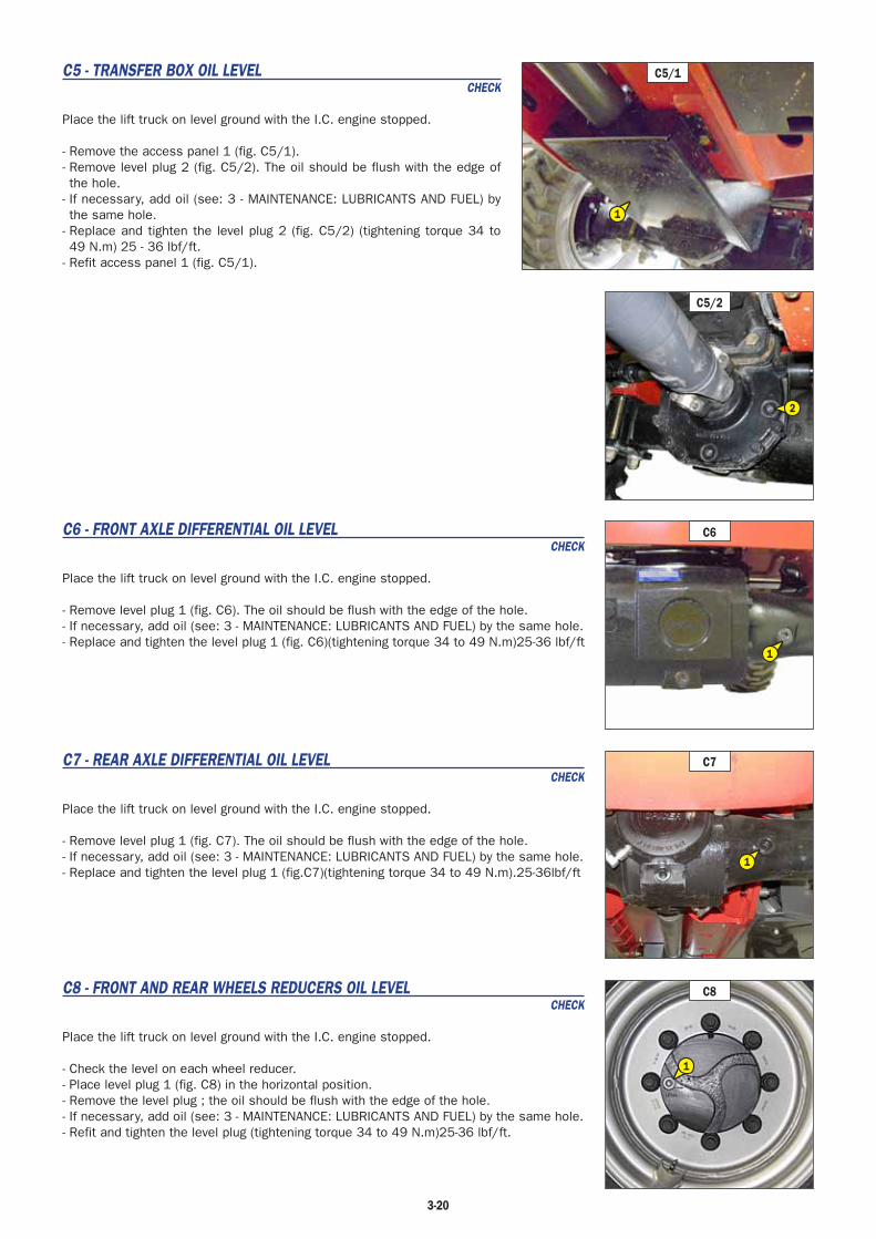
3-20
C5 - TRANSFER BOX OIL LEVELCHECK
Place the lift truck on level ground with the I.C. engine stopped.
- Remove the access panel 1 (fig. C5/1).- Remove level plug 2 (fig. C5/2). The oil should be flush with the edge of the hole.
- If necessary, add oil (see: 3 - MAINTENANCE: LUBRICANTS AND FUEL) by the same hole.
- Replace and tighten the level plug 2 (fig. C5/2) (tightening torque 34 to 49 N.m) 25 - 36 lbf/ft.
- Refit access panel 1 (fig. C5/1).
C6 - FRONT AXLE DIFFERENTIAL OIL LEVELCHECK
Place the lift truck on level ground with the I.C. engine stopped.
- Remove level plug 1 (fig. C6). The oil should be flush with the edge of the hole.- If necessary, add oil (see: 3 - MAINTENANCE: LUBRICANTS AND FUEL) by the same hole.- Replace and tighten the level plug 1 (fig. C6)(tightening torque 34 to 49 N.m)25-36 lbf/ft
C7 - REAR AXLE DIFFERENTIAL OIL LEVELCHECK
Place the lift truck on level ground with the I.C. engine stopped.
- Remove level plug 1 (fig. C7). The oil should be flush with the edge of the hole.- If necessary, add oil (see: 3 - MAINTENANCE: LUBRICANTS AND FUEL) by the same hole.- Replace and tighten the level plug 1 (fig.C7)(tightening torque 34 to 49 N.m).25-36lbf/ft
C8 - FRONT AND REAR WHEELS REDUCERS OIL LEVELCHECK
Place the lift truck on level ground with the I.C. engine stopped.
- Check the level on each wheel reducer.- Place level plug 1 (fig. C8) in the horizontal position.- Remove the level plug ; the oil should be flush with the edge of the hole.- If necessary, add oil (see: 3 - MAINTENANCE: LUBRICANTS AND FUEL) by the same hole.- Refit and tighten the level plug (tightening torque 34 to 49 N.m)25-36 lbf/ft.
C5/2
2
C6
1
C5/1
1
C7
1
C8
1

3-21
D - EVERY 500 HOURS SERVICECarry out the operations described previously as well as the following operations.
D1 - I.C. ENGINE OILDRAIN
D2 - I.C. ENGINE OIL FILTERCHANGE
Place the lift truck on level ground, let the I.C. engine run at idle for a few minutes, then stop the I.C. engine.
DRAINING THE OIL- Open the engine cover.- Remove access panel 1 (fig. D1/1).- Place a container under the drain plug and unscrew the drain plug 2 (fig. D1/2).- Remove filler cap 3 (fig. D1/3) in order to ensure that the oil is drained properly.
Dispose of the drain oil in an ecological manner.
REPLACEMENT OF THE FILTER- Unscrew and discard the I.C. engine oil filter 4 (fig. D1/2) as well as its seal.- Clean the filter bracket with a clean, lint-free cloth.- Lightly grease the new seal before refitting the new oil filter (see: 3 - MAINTENANCE: FILTERS AND BELTS) on its bracket.
Tighten the oil filter by hand pressure only and lock the filter in place by a quarter turn.
FILLING UP THE OIL- Refit and tighten drain plug 2 (fig. D1/2).- Fill up with oil (see: 3 - MAINTENANCE: LUBRICANTS AND FUEL) through filler port 5 (fig. D1/3).
- Wait a few minutes to allow the oil to flow into the sump.- Start the I.C. engine and let it run for a few minutes.- Check for possible leaks from the drain plug and the oil filter.- Stop the I.C. engine, wait a few minutes and check the correct level on the dipstick 6 (fig. D1/3) between the two level marks.
- Top up the level if necessary.- Refit access panel 1 (fig. D1/1).
D3 - DRY AIR FILTER CARTRIDGECHANGE
In case of use in a heavily dust laden atmosphere, there are pre-filtration cartridges, see: 3 - MAINTENANCE: FILTERS CARTRIDGES AND BELTS. Also, the checking and cleaning periodicity of the cartridge must be reduced (up to 250 hours in a heavily laden dust atmosphere and with pre-filtration).
Change the cartridge in a clean location, with the I.C. engine stopped. Never operate the lift truck withthe air filter removed or damaged.
- Open the I.C. engine bonnet.- Loosen the bolts and remove cover 1 (fig. D3).- Gently remove the cartridge 2 (fig. D3), taking care to avoid spilling the dust.- Leave the safety cartridge in place.- The following parts must be cleaned with a damp, clean lint-free cloth.
• The inside of the filter and cover.• The inside of the filter inlet hose.• The gasket surfaces in the filter and in the cover.
- Check pipes and connections between the air filter and the I.C. engine and the connection and state of the clogging indicator on the filter.
- Before mounting check the condition of the new cartridge (see: 3 - MAINTENANCE: FILTERS CARTRIDGES AND BELTS).- Introduce the cartridge into the filter axis and push it in, pressing the edges and not the middle.- Reassemble the cover, guiding the valve downwards.
D1/1
1
D1/3
5
6
3
D31
2
D1/2
2
4
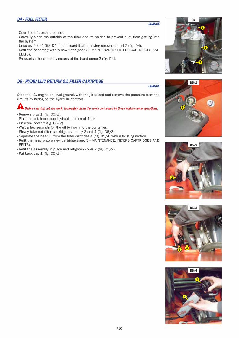
3-22
D4 - FUEL FILTERCHANGE
- Open the I.C. engine bonnet.- Carefully clean the outside of the filter and its holder, to prevent dust from getting into the system.
- Unscrew filter 1 (fig. D4) and discard it after having recovered part 2 (fig. D4).- Refit the assembly with a new filter (see: 3 - MAINTENANCE: FILTERS CARTRIDGES AND BELTS).
- Pressurise the circuit by means of the hand pump 3 (fig. D4).
D5 - HYDRAULIC RETURN OIL FILTER CARTRIDGECHANGE
Stop the I.C. engine on level ground, with the jib raised and remove the pressure from the circuits by acting on the hydraulic controls.
Before carrying out any work, thoroughly clean the areas concerned by these maintenance operations.
- Remove plug 1 (fig. D5/1);- Place a container under hydraulic return oil filter.- Unscrew cover 2 (fig. D5/2).- Wait a few seconds for the oil to flow into the container.- Slowly take out filter cartridge assembly 3 and 4 (fig. D5/3).- Separate the head 3 from the filter cartridge 4 (fig. D5/4) with a twisting motion.- Refit the head onto a new cartridge (see: 3 - MAINTENANCE: FILTERS CARTRIDGES AND BELTS).
- Refit the assembly in place and retighten cover 2 (fig. D5/2).- Put back cap 1 (fig. D5/1).
D4
2
1
3
D5/1
1
D5/2
2
D5/3
3 4
D5/4
3
4
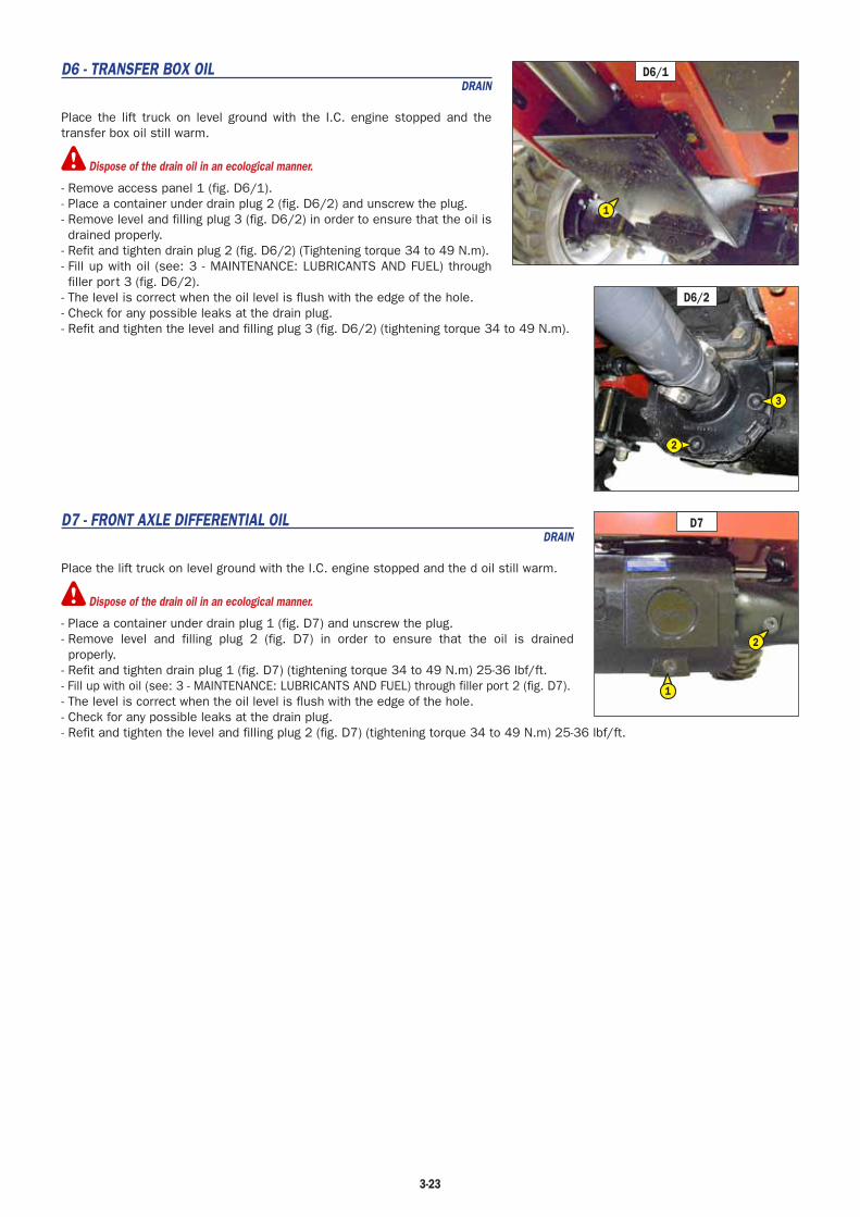
3-23
D6 - TRANSFER BOX OILDRAIN
Place the lift truck on level ground with the I.C. engine stopped and the transfer box oil still warm.
Dispose of the drain oil in an ecological manner.
- Remove access panel 1 (fig. D6/1).- Place a container under drain plug 2 (fig. D6/2) and unscrew the plug.- Remove level and filling plug 3 (fig. D6/2) in order to ensure that the oil is drained properly.
- Refit and tighten drain plug 2 (fig. D6/2) (Tightening torque 34 to 49 N.m).- Fill up with oil (see: 3 - MAINTENANCE: LUBRICANTS AND FUEL) through filler port 3 (fig. D6/2).
- The level is correct when the oil level is flush with the edge of the hole.- Check for any possible leaks at the drain plug.- Refit and tighten the level and filling plug 3 (fig. D6/2) (tightening torque 34 to 49 N.m).
D7 - FRONT AXLE DIFFERENTIAL OILDRAIN
Place the lift truck on level ground with the I.C. engine stopped and the d oil still warm.
Dispose of the drain oil in an ecological manner.
- Place a container under drain plug 1 (fig. D7) and unscrew the plug.- Remove level and filling plug 2 (fig. D7) in order to ensure that the oil is drained properly.
- Refit and tighten drain plug 1 (fig. D7) (tightening torque 34 to 49 N.m) 25-36 lbf/ft.- Fill up with oil (see: 3 - MAINTENANCE: LUBRICANTS AND FUEL) through filler port 2 (fig. D7).- The level is correct when the oil level is flush with the edge of the hole.- Check for any possible leaks at the drain plug.- Refit and tighten the level and filling plug 2 (fig. D7) (tightening torque 34 to 49 N.m) 25-36 lbf/ft.
D7
2
1
D6/2
3
2
D6/1
1

3-24

3-25
E - EVERY 1000 HOURS OF SERVICECarry out the operations described previously as well as the following operations.
E1 - FUEL TANKCLEAN
While carrying out these operations, do not smoke or work near a flame.
Place the lift truck on level ground with the I.C. engine stopped.
- Inspect the parts susceptible to leaks in the fuel circuit and in the tank.- In the event of a leak, contact your dealer.
Never try to carry out a weld or any other operation by yourself, this could provoke an explosion or afire.
- Place a container under drain plug 1 (fig. E1/1) and unscrew the plug.- Open access panel 2 (fig. E1/2).- Remove filler plug 3 (fig. E1/2) in order to ensure that the oil is drained properly.- Rinse out with ten litres of clean diesel through filler port 4 (fig. E1/2).- Refit and tighten the drain plug (tightening torque 29 to 39 N.m) 21-29 lbf/ft.- Fill the fuel tank with clean diesel filtered through the filler port.- Refit the filler plug.- Close the access panel.- If necessary, bleed the fuel circuit (see: 3 - MAINTENANCE: G1 - FUEL SYSTEM).
E2 - SAFETY DRY AIR FILTER CARTRIDGECHANGE
- For the disassembly and reassembly of the dry air filter cartridge, see: 3 - MAINTENANCE: D3 - AIR FILTER CARTRIDGE.
- Gently remove the dry air filter safety cartridge 1 (fig. E2), taking care to avoid spilling the dust.
- Clean the gasket surface on the filter with a damp, clean lint-free cloth.- Check the condition of the new safety cartridge before fitting (see: 3 - MAINTENANCE: FILTERS AND BELTS).
- Insert the cartridge within the axis of the filter and push it home, pressing against the outer edge and not the centre.
NOTE: The safety cartridge changing frequency is given for information only. It must be changed for every two changes of the dry air filter cartridge.
E2
1
E1/2
4
2
3
E1/1
1
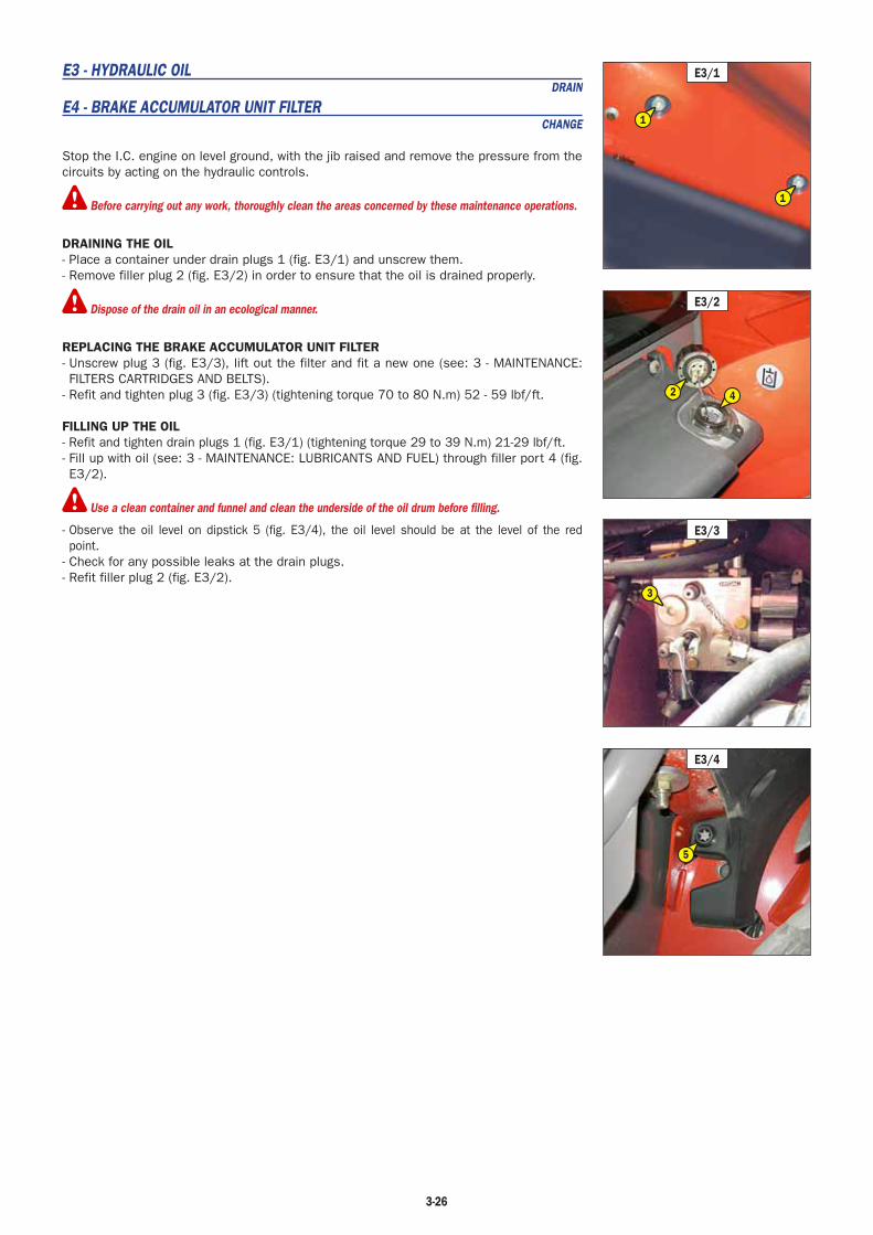
3-26
E3 - HYDRAULIC OILDRAIN
E4 - BRAKE ACCUMULATOR UNIT FILTERCHANGE
Stop the I.C. engine on level ground, with the jib raised and remove the pressure from the circuits by acting on the hydraulic controls.
Before carrying out any work, thoroughly clean the areas concerned by these maintenance operations.
DRAINING THE OIL- Place a container under drain plugs 1 (fig. E3/1) and unscrew them.- Remove filler plug 2 (fig. E3/2) in order to ensure that the oil is drained properly.
Dispose of the drain oil in an ecological manner.
REPLACING THE BRAKE ACCUMULATOR UNIT FILTER- Unscrew plug 3 (fig. E3/3), lift out the filter and fit a new one (see: 3 - MAINTENANCE: FILTERS CARTRIDGES AND BELTS).
- Refit and tighten plug 3 (fig. E3/3) (tightening torque 70 to 80 N.m) 52 - 59 lbf/ft.
FILLING UP THE OIL- Refit and tighten drain plugs 1 (fig. E3/1) (tightening torque 29 to 39 N.m) 21-29 lbf/ft.- Fill up with oil (see: 3 - MAINTENANCE: LUBRICANTS AND FUEL) through filler port 4 (fig. E3/2).
Use a clean container and funnel and clean the underside of the oil drum before filling.
- Observe the oil level on dipstick 5 (fig. E3/4), the oil level should be at the level of the red point.
- Check for any possible leaks at the drain plugs.- Refit filler plug 2 (fig. E3/2).
E3/1
1
1
E3/3
3
E3/2
42
E3/4
5
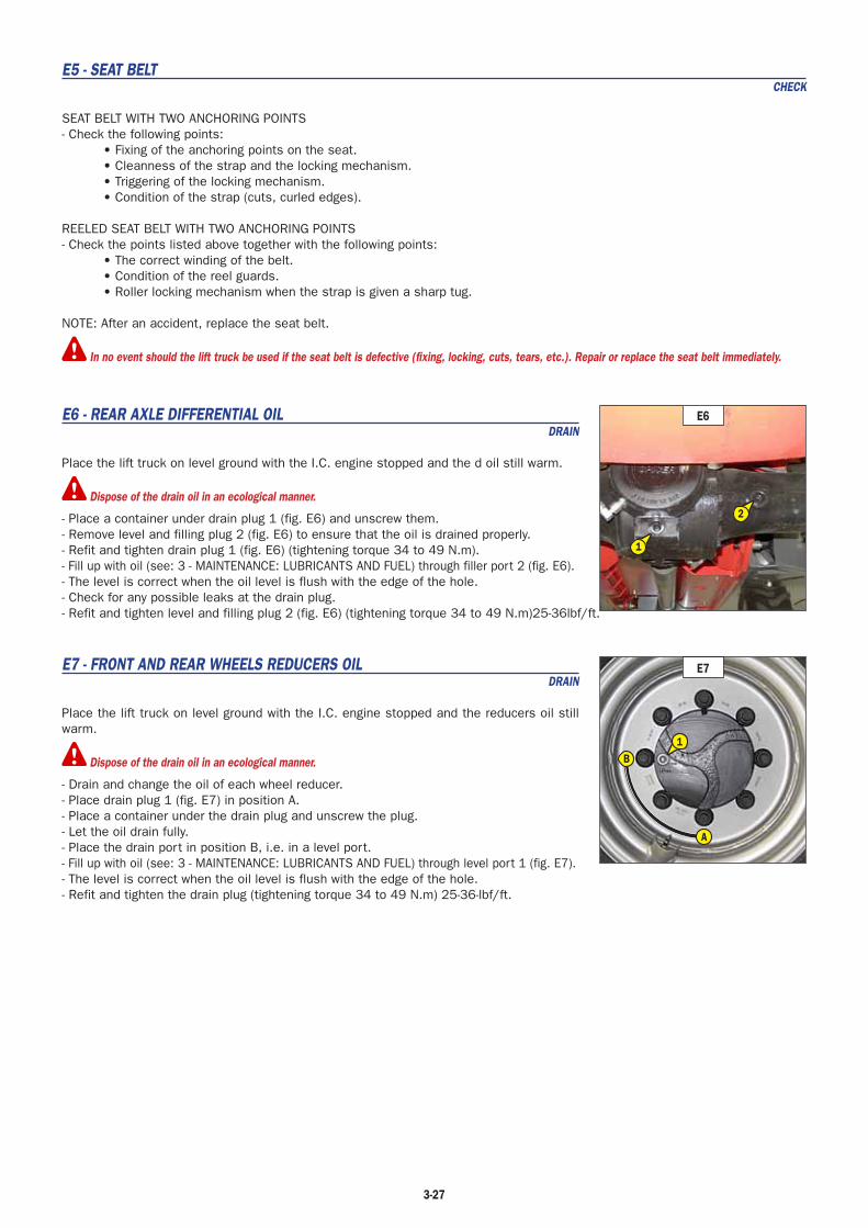
3-27
E5 - SEAT BELTCHECK
SEAT BELT WITH TWO ANCHORING POINTS- Check the following points:
• Fixing of the anchoring points on the seat.• Cleanness of the strap and the locking mechanism.• Triggering of the locking mechanism.• Condition of the strap (cuts, curled edges).
REELED SEAT BELT WITH TWO ANCHORING POINTS- Check the points listed above together with the following points:
• The correct winding of the belt.• Condition of the reel guards.• Roller locking mechanism when the strap is given a sharp tug.
NOTE: After an accident, replace the seat belt.
In no event should the lift truck be used if the seat belt is defective (fixing, locking, cuts, tears, etc.). Repair or replace the seat belt immediately.
E6 - REAR AXLE DIFFERENTIAL OILDRAIN
Place the lift truck on level ground with the I.C. engine stopped and the d oil still warm.
Dispose of the drain oil in an ecological manner.
- Place a container under drain plug 1 (fig. E6) and unscrew them.- Remove level and filling plug 2 (fig. E6) to ensure that the oil is drained properly.- Refit and tighten drain plug 1 (fig. E6) (tightening torque 34 to 49 N.m).- Fill up with oil (see: 3 - MAINTENANCE: LUBRICANTS AND FUEL) through filler port 2 (fig. E6).- The level is correct when the oil level is flush with the edge of the hole.- Check for any possible leaks at the drain plug.- Refit and tighten level and filling plug 2 (fig. E6) (tightening torque 34 to 49 N.m)25-36lbf/ft.
E7 - FRONT AND REAR WHEELS REDUCERS OILDRAIN
Place the lift truck on level ground with the I.C. engine stopped and the reducers oil still warm.
Dispose of the drain oil in an ecological manner.
- Drain and change the oil of each wheel reducer.- Place drain plug 1 (fig. E7) in position A.- Place a container under the drain plug and unscrew the plug.- Let the oil drain fully.- Place the drain port in position B, i.e. in a level port.- Fill up with oil (see: 3 - MAINTENANCE: LUBRICANTS AND FUEL) through level port 1 (fig. E7).- The level is correct when the oil level is flush with the edge of the hole.- Refit and tighten the drain plug (tightening torque 34 to 49 N.m) 25-36-lbf/ft.
E7
B
A
1
E6
1
2

3-28
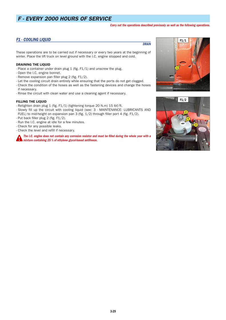
3-29
F - EVERY 2000 HOURS OF SERVICECarry out the operations described previously as well as the following operations.
F1 - COOLING LIQUIDDRAIN
These operations are to be carried out if necessary or every two years at the beginning of winter. Place the lift truck on level ground with the I.C. engine stopped and cold.
DRAINING THE LIQUID- Place a container under drain plug 1 (fig. F1/1) and unscrew the plug.- Open the I.C. engine bonnet.- Remove expansion pan filler plug 2 (fig. F1/2).- Let the cooling circuit drain entirely while ensuring that the ports do not get clogged.- Check the condition of the hoses as well as the fastening devices and change the hoses if necessary.
- Rinse the circuit with clean water and use a cleaning agent if necessary.
FILLING THE LIQUID- Retighten drain plug 1 (fig. F1/1) (tightening torque 20 N.m) 15 lbf/ft.- Slowly fill up the circuit with cooling liquid (see: 3 - MAINTENANCE: LUBRICANTS AND FUEL) to mid-height on expansion pan 3 (fig. 1/2) through filler port 4 (fig. F1/2).
- Put back filler plug 2 (fig. F1/2).- Run the I.C. engine at idle for a few minutes.- Check for any possible leaks.- Check the level and refill if necessary.
The I.C. engine does not contain any corrosion resistor and must be filled during the whole year with amixture containing 25 % of ethylene glycol-based antifreeze.
F1/1
1
F1/2
3
2
4
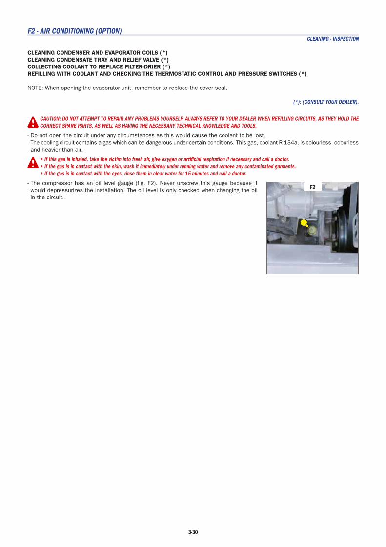
3-30
F2 - AIR CONDITIONING (OPTION)CLEANING - INSPECTION
CLEANING CONDENSER AND EVAPORATOR COILS (*)CLEANING CONDENSATE TRAY AND RELIEF VALVE (*)COLLECTING COOLANT TO REPLACE FILTER-DRIER (*)REFILLING WITH COOLANT AND CHECKING THE THERMOSTATIC CONTROL AND PRESSURE SWITCHES (*)
NOTE: When opening the evaporator unit, remember to replace the cover seal.
(*): (CONSULT YOUR DEALER).
CAUTION: DO NOT ATTEMPT TO REPAIR ANY PROBLEMS YOURSELF. ALWAYS REFER TO YOUR DEALER WHEN REFILLING CIRCUITS, AS THEY HOLD THECORRECT SPARE PARTS, AS WELL AS HAVING THE NECESSARY TECHNICAL KNOWLEDGE AND TOOLS.
- Do not open the circuit under any circumstances as this would cause the coolant to be lost.- The cooling circuit contains a gas which can be dangerous under certain conditions. This gas, coolant R 134a, is colourless, odourless and heavier than air.
• If this gas is inhaled, take the victim into fresh air, give oxygen or artificial respiration if necessary and call a doctor.• If the gas is in contact with the skin, wash it immediately under running water and remove any contaminated garments.• If the gas is in contact with the eyes, rinse them in clear water for 15 minutes and call a doctor.
- The compressor has an oil level gauge (fig. F2). Never unscrew this gauge because it would depressurizes the installation. The oil level is only checked when changing the oil in the circuit.
F2
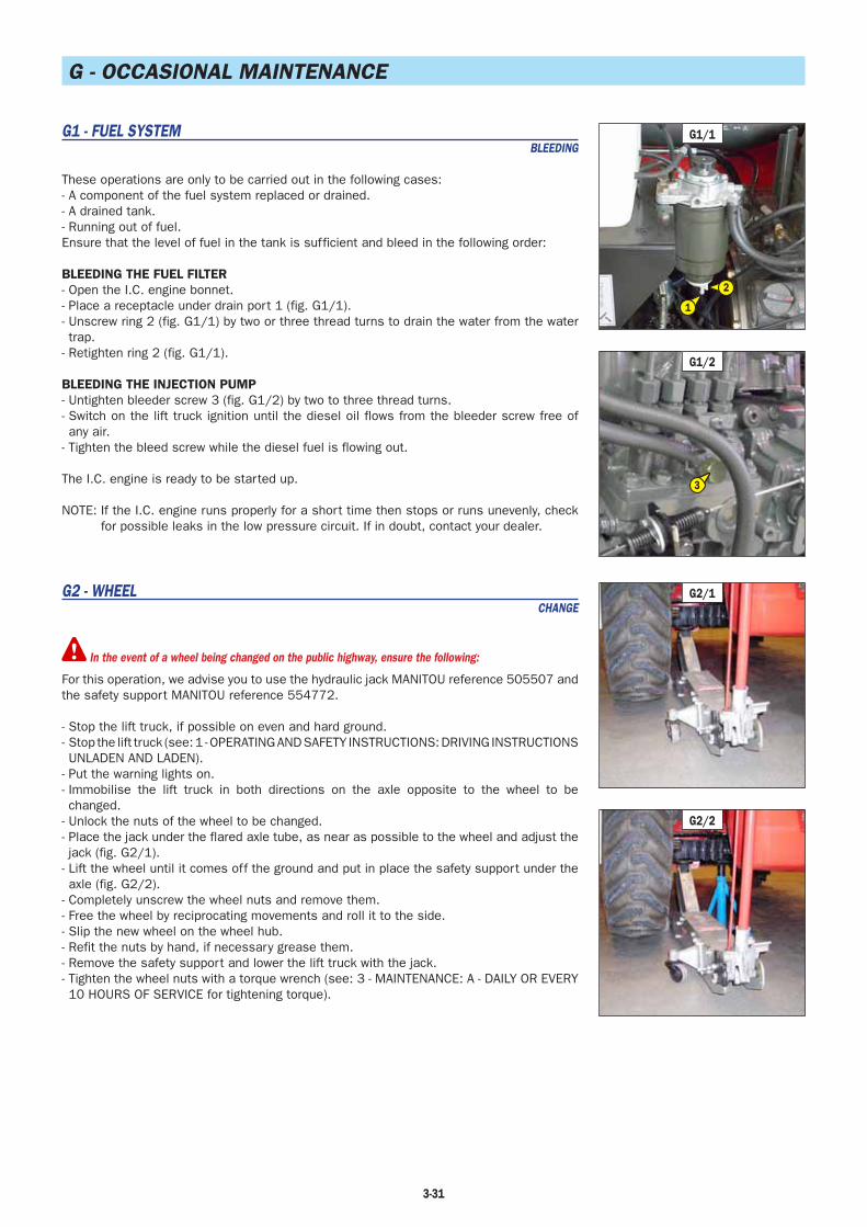
3-31
G - OCCASIONAL MAINTENANCE
G1 - FUEL SYSTEMBLEEDING
These operations are only to be carried out in the following cases:- A component of the fuel system replaced or drained.- A drained tank.- Running out of fuel.Ensure that the level of fuel in the tank is sufficient and bleed in the following order:
BLEEDING THE FUEL FILTER- Open the I.C. engine bonnet.- Place a receptacle under drain port 1 (fig. G1/1).- Unscrew ring 2 (fig. G1/1) by two or three thread turns to drain the water from the water trap.
- Retighten ring 2 (fig. G1/1).
BLEEDING THE INJECTION PUMP- Untighten bleeder screw 3 (fig. G1/2) by two to three thread turns.- Switch on the lift truck ignition until the diesel oil flows from the bleeder screw free of any air.
- Tighten the bleed screw while the diesel fuel is flowing out.
The I.C. engine is ready to be started up.
NOTE: If the I.C. engine runs properly for a short time then stops or runs unevenly, check for possible leaks in the low pressure circuit. If in doubt, contact your dealer.
G2 - WHEELCHANGE
In the event of a wheel being changed on the public highway, ensure the following:
For this operation, we advise you to use the hydraulic jack MANITOU reference 505507 and the safety support MANITOU reference 554772.
- Stop the lift truck, if possible on even and hard ground.- Stop the lift truck (see: 1 - OPERATING AND SAFETY INSTRUCTIONS: DRIVING INSTRUCTIONS UNLADEN AND LADEN).
- Put the warning lights on.- Immobilise the lift truck in both directions on the axle opposite to the wheel to be changed.
- Unlock the nuts of the wheel to be changed.- Place the jack under the flared axle tube, as near as possible to the wheel and adjust the jack (fig. G2/1).
- Lift the wheel until it comes off the ground and put in place the safety support under the axle (fig. G2/2).
- Completely unscrew the wheel nuts and remove them.- Free the wheel by reciprocating movements and roll it to the side.- Slip the new wheel on the wheel hub.- Refit the nuts by hand, if necessary grease them.- Remove the safety support and lower the lift truck with the jack.- Tighten the wheel nuts with a torque wrench (see: 3 - MAINTENANCE: A - DAILY OR EVERY 10 HOURS OF SERVICE for tightening torque).
G2/1
G2/2
G1/2
3
G1/1
2
1
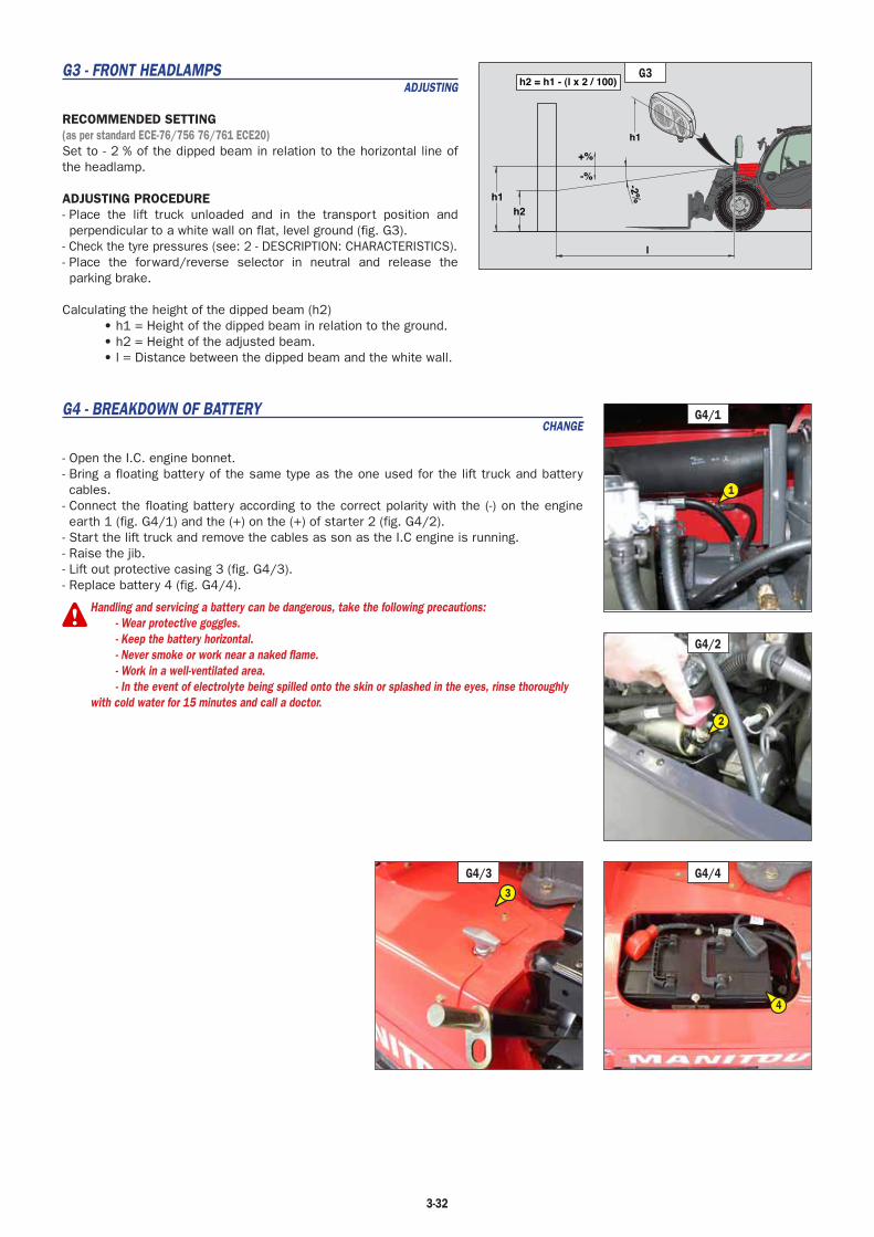
3-32
G3 - FRONT HEADLAMPSADJUSTING
RECOMMENDED SETTING(as per standard ECE-76/756 76/761 ECE20)Set to - 2 % of the dipped beam in relation to the horizontal line of the headlamp.
ADJUSTING PROCEDURE- Place the lift truck unloaded and in the transport position and perpendicular to a white wall on flat, level ground (fig. G3).
- Check the tyre pressures (see: 2 - DESCRIPTION: CHARACTERISTICS).- Place the forward/reverse selector in neutral and release the parking brake.
Calculating the height of the dipped beam (h2)• h1 = Height of the dipped beam in relation to the ground.• h2 = Height of the adjusted beam.• l = Distance between the dipped beam and the white wall.
G4 - BREAKDOWN OF BATTERYCHANGE
- Open the I.C. engine bonnet.- Bring a floating battery of the same type as the one used for the lift truck and battery cables.
- Connect the floating battery according to the correct polarity with the (-) on the engine earth 1 (fig. G4/1) and the (+) on the (+) of starter 2 (fig. G4/2).
- Start the lift truck and remove the cables as son as the I.C engine is running.- Raise the jib.- Lift out protective casing 3 (fig. G4/3).- Replace battery 4 (fig. G4/4).
Handling and servicing a battery can be dangerous, take the following precautions: - Wear protective goggles. - Keep the battery horizontal. - Never smoke or work near a naked flame. - Work in a well-ventilated area. - In the event of electrolyte being spilled onto the skin or splashed in the eyes, rinse thoroughlywith cold water for 15 minutes and call a doctor.
+%
-%
l
h1h2
-2%
h2 = h1 - (l x 2 / 100)
h1
G3
G4/2
2
G4/33
G4/1
1
G4/4
4

3-33
A B
G6/1
1
1
G5/1
1
1
G5/2
22 33
G6/3G6/2
G5 - LIFT TRUCKTOWING
If the lift truck is not on horizontal ground, chock its wheels it to prevent it rolling down the slope.
The lift truck must be towed at very slow speed (less than 5 km/h) 3.1 mph over the shortest possible distance (less than 100 m) 328 ft.
For towing a lift truck, the high pressure limiters must be unlocked to avoid damaging the hydrostatic transmission, and the parking brake on the front axle must be released.
- Switch on lift truck ignition.- Set the forward/reverse selector to neutral.- Release the parking brake.
UNLOCKING THE HIGH PRESSURE LIMITERS- Open the I.C. engine bonnet.- Loosen nuts 1 (fig. G5/1) on the hydrostatic pump by no more than three turns.
RELEASING THE PARKING BRAKE ON THE FRONT AXLE- Unscrew the screws 2 (fig. G5/2) on the front axle, remove the shims 3 (fig. G5/2) and fully retighten the screws 2 (fig. G5/2).
TOWING- Switch on the warning lights.- If the I.C. engine is not running there will be no steering or braking assistance. Operate the steering and pedal slowly avoiding sudden jerky movements.
- After towing, retighten screws 1 (fig. G5/1) (tightening torque 70 N.m) 51.6 lbf/ft.- Unscrew the screws 2 (fig. G5/2), refit the 3 shims (fig. G5/2) and retighten the screws 2 (fig. G5/2) (tightening torque 95 - 115 N.m) 70-85 lbf/ft.
G6 - LIFT TRUCKSLINGING
- Take into account the position of the lift truck centre of gravity for lifting (fig. G6/1).
A = 1,200 mm B = 1,100 mm- Place the hooks in the fastening points provided (fig. G6/2 and G6/3).
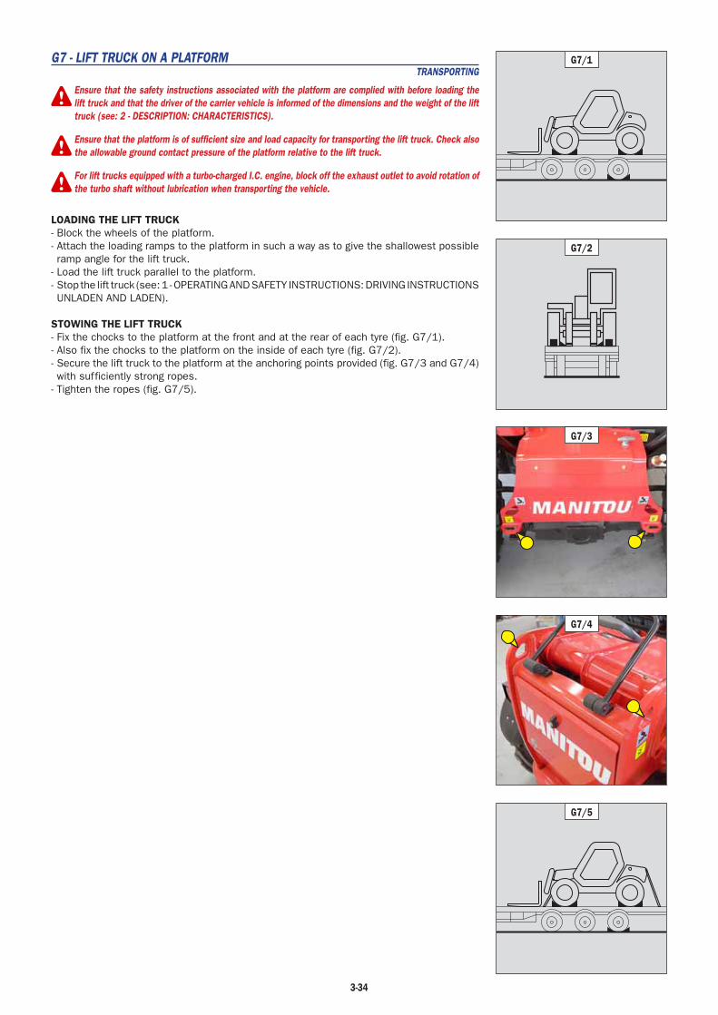
3-34
G7 - LIFT TRUCK ON A PLATFORMTRANSPORTING
Ensure that the safety instructions associated with the platform are complied with before loading thelift truck and that the driver of the carrier vehicle is informed of the dimensions and the weight of the lifttruck (see: 2 - DESCRIPTION: CHARACTERISTICS).
Ensure that the platform is of sufficient size and load capacity for transporting the lift truck. Check alsothe allowable ground contact pressure of the platform relative to the lift truck.
For lift trucks equipped with a turbo-charged I.C. engine, block off the exhaust outlet to avoid rotation ofthe turbo shaft without lubrication when transporting the vehicle.
LOADING THE LIFT TRUCK- Block the wheels of the platform.- Attach the loading ramps to the platform in such a way as to give the shallowest possible ramp angle for the lift truck.
- Load the lift truck parallel to the platform.- Stop the lift truck (see: 1 - OPERATING AND SAFETY INSTRUCTIONS: DRIVING INSTRUCTIONS UNLADEN AND LADEN).
STOWING THE LIFT TRUCK- Fix the chocks to the platform at the front and at the rear of each tyre (fig. G7/1).- Also fix the chocks to the platform on the inside of each tyre (fig. G7/2).- Secure the lift truck to the platform at the anchoring points provided (fig. G7/3 and G7/4) with sufficiently strong ropes.
- Tighten the ropes (fig. G7/5).
G7/1
G7/2
G7/5
G7/4
G7/3

3-35

3-36

4-1
4 - OPTIONALATTACHMENTSFOR USE WITHTHE RANGE

4-2

4-3
TABLE OF CONTENTS
INTRODUCTION 4-5
PICKING UP THE ATTACHMENTS 4-6
TECHNICAL SPECIFICATIONS OF ATTACHMENTS 4-8
ATTACHMENT SHIELDS 4-10

4-5
INTRODUCTION
- Your lift truck must be used with interchangeable equipment. These items are called: ATTACHMENTS.
- A wide range of attachments is available, guaranteed by MANITOU and designed to fit your lift truck perfectly.
- The attachments are delivered with a load chart concerning your lift truck. The operator’s manual and the load chart should be kept in the places provided in the lift truck. For standard attachments, their use is governed by the instructions contained on this notice.
- Some particular uses require the adaptation of the attachment which is not provided in the price-listed options. Optional solutions exist, consult your dealer.
Suspended loads MUST be handled with a lift truck designed for that purpose (see: 1 - OPERATING AND SAFETY INSTRUCTIONS: LOAD HANDLINGINSTRUCTIONS: H - TAKING-UP AND SETTING-DOWN A SUSPENDED LOAD).
Only attachments approved by MANITOU are to be used on our lift trucks (see: 4 - ADAPTABLE ATTACHMENTS IN OPTION ON THE RANGE: TECHNICALSPECIFICATIONS OF ATTACHMENTS). The manufacturer shall not be liable for any modification or adaptation of an attachment made without itsknowledge.
Depending on their size, certain attachments may, when the jib is lowered and retracted, come into contact with the front tyres and cause damageto them, if reverse tilt is activated in the forward tilt direction. TO PREVENT THIS RISK, EXTEND THE TELESCOPE TO A SUFFICIENT EXTENT FOR THEPARTICULAR LIFT TRUCK AND ATTACHMENT SO THAT THIS CONTACT IS NOT POSSIBLE.
Maximum loads are defined by the capacity of a lift truck taking account of the attachment’s mass and centre of gravity. In the event of the attachmenthaving less capacity than the lift truck, never exceed this limit.
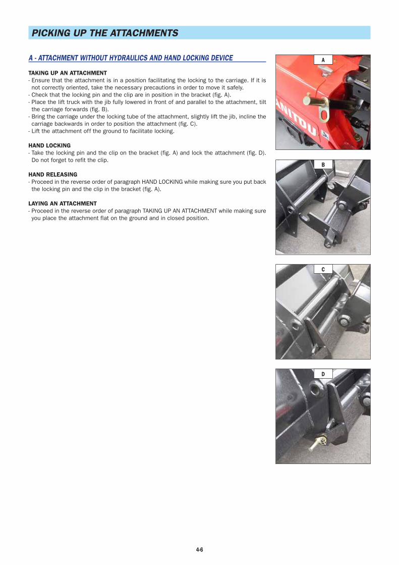
4-6
PICKING UP THE ATTACHMENTS
A - ATTACHMENT WITHOUT HYDRAULICS AND HAND LOCKING DEVICE
TAKING UP AN ATTACHMENT- Ensure that the attachment is in a position facilitating the locking to the carriage. If it is not correctly oriented, take the necessary precautions in order to move it safely.
- Check that the locking pin and the clip are in position in the bracket (fig. A).- Place the lift truck with the jib fully lowered in front of and parallel to the attachment, tilt the carriage forwards (fig. B).
- Bring the carriage under the locking tube of the attachment, slightly lift the jib, incline the carriage backwards in order to position the attachment (fig. C).
- Lift the attachment off the ground to facilitate locking.
HAND LOCKING- Take the locking pin and the clip on the bracket (fig. A) and lock the attachment (fig. D).Do not forget to refit the clip.
HAND RELEASING- Proceed in the reverse order of paragraph HAND LOCKING while making sure you put back the locking pin and the clip in the bracket (fig. A).
LAYING AN ATTACHMENT- Proceed in the reverse order of paragraph TAKING UP AN ATTACHMENT while making sure you place the attachment flat on the ground and in closed position.
A
B
C
D
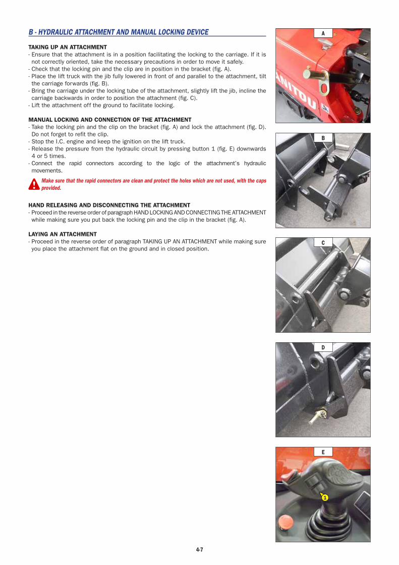
4-7
B - HYDRAULIC ATTACHMENT AND MANUAL LOCKING DEVICE
TAKING UP AN ATTACHMENT- Ensure that the attachment is in a position facilitating the locking to the carriage. If it is not correctly oriented, take the necessary precautions in order to move it safely.
- Check that the locking pin and the clip are in position in the bracket (fig. A).- Place the lift truck with the jib fully lowered in front of and parallel to the attachment, tilt the carriage forwards (fig. B).
- Bring the carriage under the locking tube of the attachment, slightly lift the jib, incline the carriage backwards in order to position the attachment (fig. C).
- Lift the attachment off the ground to facilitate locking.
MANUAL LOCKING AND CONNECTION OF THE ATTACHMENT- Take the locking pin and the clip on the bracket (fig. A) and lock the attachment (fig. D).Do not forget to refit the clip.
- Stop the I.C. engine and keep the ignition on the lift truck.- Release the pressure from the hydraulic circuit by pressing button 1 (fig. E) downwards 4 or 5 times.
- Connect the rapid connectors according to the logic of the attachment’s hydraulic movements.
Make sure that the rapid connectors are clean and protect the holes which are not used, with the capsprovided.
HAND RELEASING AND DISCONNECTING THE ATTACHMENT- Proceed in the reverse order of paragraph HAND LOCKING AND CONNECTING THE ATTACHMENT while making sure you put back the locking pin and the clip in the bracket (fig. A).
LAYING AN ATTACHMENT- Proceed in the reverse order of paragraph TAKING UP AN ATTACHMENT while making sure you place the attachment flat on the ground and in closed position.
E
1
A
B
C
D

4-8

(18/11/2010) 80-02-M176FR
80
MAIN ÉLECTRIC SHEMATIC
pages
CODES ON ÉLECTRICAL SCHEMATIC....... . . . . . . . . . . . . . . . . . . . . . . . . . . . . . . . .A3
CÂBLES LABELS ON THE ÉLECTRICAL HARNESS. . . . . . . . . . . . . . . . . . . .A4
ELECTRICAL SCHÉMATIC
MT 625 Turbo . . . . . . . . . . . . . . . . . . . . . . . . . . . . . . . . . . . . . . . . . . . . . . . B
MT 625 T COMFORT / MLT 625-75 H . . . . . . . . . . . . . . . . . . . . . . . . . . . . . . C
–
–

(18/11/2010)80-02-M176FR
80
A2 Main Electrical Schématic

(18/11/2010) 80-02-M176FR
80
A3 Main Electrical Schématic
CODES ON ELECTRICAL SCHÉMATIC
M
K
I
G
E
C
A
21 3 4 5 6 7 8 9 10 11 12 13 14 15 16 17 18 19
CA
N A
H
Mas
se C
AN
A
CA
N A
L
CA
N A
H
CA
N A
L
V Bat
Masse Chassis M
1
Masse Chassis M
3
B16
B15
JSM
S15
S16
S25 R
F
N
--
++
F4
F3
Y40
Y28
A2 / MP 22
A1 / MP 12
A12
BF1 / M1
X116
X67
X162
CN1-P1 / X148
CN2-P1 / X149
CN2-P2 / X151
CN1-P2 / X150
X160
X201
EP6
EP5
EP68
238
237
236
235
234
2336
7
174
183
182
179
172
178
176
175
177
173
232
180
86
88
90
87
89
91
440
420
421
420
2
1
2
1
58
71 72
41 4211
72
12
11
8
1
7
5
4
6
3
2
10
9
59
82
19
86
85
89
49
34
88
56
87
30
16
17
46
47
76
77
1
2
76
47
46
77
17
16
5
11
13
15
1
4
6
7
8
8
2
2
14
12
9
10
2
Example labeling of the câbles and the components on the wiring diagram.
Légende:1 - Feed 2 - Electrical Component 3 - Description electrical component4 - Electrical Connector 5 - Déscription electrical connector6 - Splicing7 - Connector ECU8 - ECU
9 - Déscription ECU10 - Déscription connector ECU11 - Déscription N° wire12 - Déscription N° PIN electrical connector 13 - Masses14 - CAN15 - Shield CAN16 - Grid location
3
16

(18/11/2010)80-02-M176FR
80
A4 Main Electrical Schématic
CÂBLE LABELING ON THE ÉLECTRICAL HARNESS
Electric harness installed in the carriage are made with connectors. In order to identify the conectors and their wires to which are attached, inscriptions are on each wire.
X32/88/X64
Support
Ending
X32
X64
X32 / 88 / X64 X32 / 88 / X64
N° wire
(09/02/2011) 80-02-M176FR
80
C1Main Electrical Schématic
1 - START / DIGICODE CLIENT . . . . . . . . . . . . . . . . . . . . . . . . . . . . . . . . . . . . . . . . . . C7
2 - CAN H-L / OUTLET OBD (DIAGNOSTIC). . . . . . . . . . . . . . . . . . . . . . . . . . . . . . . . . . C11
3 - TRANSMISSION . . . . . . . . . . . . . . . . . . . . . . . . . . . . . . . . . . . . . . . . . . . . . . . . . . C15
4 - HYDRAULIC MOVEMENT. . . . . . . . . . . . . . . . . . . . . . . . . . . . . . . . . . . . . . . . . . . . C19
5 - ILLUMINATION SIGNALS / VENTILATION. . . . . . . . . . . . . . . . . . . . . . . . . . . . . . . . . C23
6 - OPTIONS. . . . . . . . . . . . . . . . . . . . . . . . . . . . . . . . . . . . . . . . . . . . . . . . . . . . . . . C29
pagesMT 625 T COMFORT / MLT 625-75 H
POSITION OF THE CONNECTORS PER SCHÉMATIC . . . . . . . . . . . . . . . . . . . . . . . . . . . . .C3
ÉLECTRICAL SCHEMATIC PER FUNCTION :

(09/02/2011)80-02-M176FR
80
C2 Main Electrical Schématic MT 625 T COMFORT/ MLT 625-75 H

(09/02/2011) 80-02-M176FR
80
C3 Main Electrical Schématic MT 625 T COMFORT/ MLT 625-75 H
POSITION OF THE CONNECTORS PER SCHÉMATIC
Connecteurs Sch. 1 Sch. 2 Sch. 3 Sch. 4 Sch. 5 Sch. 6
X0 ✔
X1 ✔
X2 ✔
X3 ✔
X4 ✔
X6 ✔
X8 ✔
X11 ✔
X12 ✔
X13 ✔ ✔ ✔
X14 ✔
X17 ✔
X18 ✔
X19 ✔ ✔
X20 ✔
X21 ✔
X22 ✔
X25 ✔
X26 ✔
X27 ✔
X28 ✔
X29 ✔
X30 ✔
X31 ✔
X32 ✔
X35 ✔
X36 ✔
X37 ✔
X38 ✔
X39 ✔
X40 ✔
X41 ✔
X46 ✔
X47 ✔
X50 ✔
X56 ✔ ✔ ✔
X57 ✔ ✔ ✔
X58 ✔
X59 ✔
X62 ✔
X63 ✔
X64 ✔
X65 ✔
X66 ✔ ✔
X67 ✔ ✔ ✔
X91 ✔
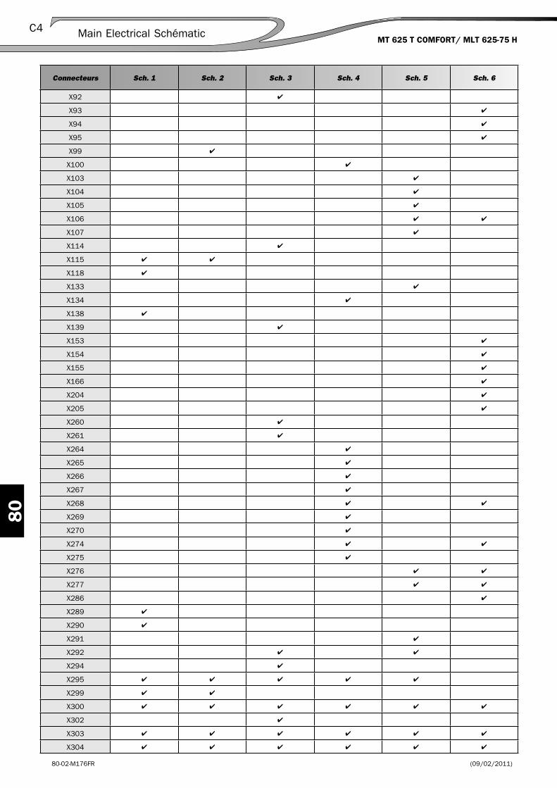
(09/02/2011)80-02-M176FR
80
C4 Main Electrical Schématic MT 625 T COMFORT/ MLT 625-75 H
Connecteurs Sch. 1 Sch. 2 Sch. 3 Sch. 4 Sch. 5 Sch. 6
X92 ✔
X93 ✔
X94 ✔
X95 ✔
X99 ✔
X100 ✔
X103 ✔
X104 ✔
X105 ✔
X106 ✔ ✔
X107 ✔
X114 ✔
X115 ✔ ✔
X118 ✔
X133 ✔
X134 ✔
X138 ✔
X139 ✔
X153 ✔
X154 ✔
X155 ✔
X166 ✔
X204 ✔
X205 ✔
X260 ✔
X261 ✔
X264 ✔
X265 ✔
X266 ✔
X267 ✔
X268 ✔ ✔
X269 ✔
X270 ✔
X274 ✔ ✔
X275 ✔
X276 ✔ ✔
X277 ✔ ✔
X286 ✔
X289 ✔
X290 ✔
X291 ✔
X292 ✔ ✔
X294 ✔
X295 ✔ ✔ ✔ ✔ ✔
X299 ✔ ✔
X300 ✔ ✔ ✔ ✔ ✔ ✔
X302 ✔
X303 ✔ ✔ ✔ ✔ ✔ ✔
X304 ✔ ✔ ✔ ✔ ✔ ✔

(09/02/2011) 80-02-M176FR
80
C5 Main Electrical SchématicMT 625 T COMFORT/ MLT 625-75 H
Connecteurs Sch. 1 Sch. 2 Sch. 3 Sch. 4 Sch. 5 Sch. 6
X305 ✔ ✔
X308 ✔ ✔ ✔
X309 ✔ ✔
X310 ✔ ✔ ✔ ✔ ✔ ✔
X311 ✔ ✔
X312 ✔ ✔ ✔
X313 ✔ ✔ ✔
X314 ✔ ✔ ✔
X315 ✔ ✔
X316 ✔
X322 ✔
X321 ✔ ✔ ✔ ✔ ✔ ✔
X324 ✔
X326 ✔
X327 ✔
X330 ✔
X331 ✔ ✔
X358 ✔
X360 ✔
X362 ✔
X363 ✔ ✔
X365 ✔
X367 ✔
X368 ✔
X370 ✔
X372 ✔
X373 ✔
X374 ✔
X375 ✔
X376 ✔
X377 ✔
X378 ✔ ✔
X381 ✔ ✔
X382 ✔
X383 ✔ ✔
X385 ✔
X386 ✔

(09/02/2011)80-02-M176FR
80
C6 Main Electrical SchématicMT 625 T COMFORT/ MLT 625-75 H

(09/02/2011) 80-02-M176FR
80
C7Main Electrical Schématic MT 625 T COMFORT/ MLT 625-75 H
1 - START / DIGICODE CLIENT
X0 S1 Battery Cut off S8
Châssis X1 S2 4-way switch key A11
Châssis X2 S2 6-way switch key A15
Moteur X3 R1 Préheating Q9
Motor X4 M1 Starter Sollénoïde Q6
Motor X8 Y1/Y2 Engine stop elctrovalves S11
Châssis X13 A1 Dashboard unit I40
Châssis/Motor X1 Interface Châssis/Engine O29
Châssis X56 A3 ECU hydraulic M30
Châssis X57 A3 ECU hydraulic M39
Châssis X115 PAD Diagnostic oulet 039
Châssis X118 A6 Digicode client I5
Châssis X138 S50 Emergency Stop A7
Moteur X289 G2 Alternator 12V/80A O13
Moteur X290 G2 Supply alternator O14
Moteur X295 A2 ECU transmission M24
Moteur X299 A2 ECU transmission M27
Châssis/Moteur X310 Interface Châssis/Engine K13
A1 Dashboard unit E24
A2 ECU transmission M28
A3 ECU hydraulic M36
A6 Digicode client K8
G1 Battery 12V/110Ah O8
G2 Alternator 12V/80A Q13
M1 Start solenoid Q6
P1 Hour Meter G40
P2 Diesel Gauge Unit G37
PAD Diagnostic Outlet 039
R1 Preheating Résistance S9
S1 Battery cut off S8
S2 Key switch A11
S50 Emergency stop A7
Y1 Engine stop electrovalve 1 (continued) S11
Y2 Engine stop electrovalve 2 (appel) S13
Components
Rep. Déscription Position on schématicCorrespondance
hydraulique
Connectors
Harness type Rep.Comp.
NameDéscription
Position on schématic
Correspondance hydraulic
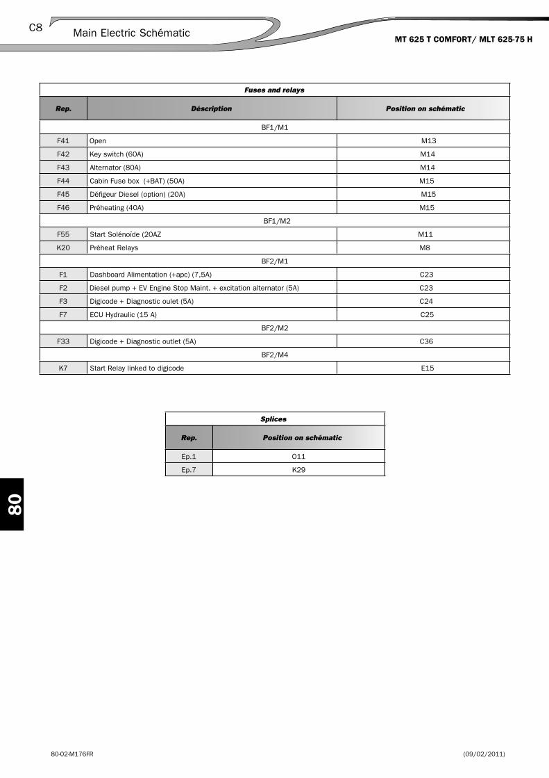
(09/02/2011)80-02-M176FR
80
C8 Main Electric Schématic MT 625 T COMFORT/ MLT 625-75 H
Fuses and relays
Rep. Déscription Position on schématic
BF1/M1
F41 Open M13
F42 Key switch (60A) M14
F43 Alternator (80A) M14
F44 Cabin Fuse box (+BAT) (50A) M15
F45 Défi geur Diesel (option) (20A) M15
F46 Préheating (40A) M15
BF1/M2
F55 Start Solénoïde (20AZ M11
K20 Préheat Relays M8
BF2/M1
F1 Dashboard Alimentation (+apc) (7,5A) C23
F2 Diesel pump + EV Engine Stop Maint. + excitation alternator (5A) C23
F3 Digicode + Diagnostic oulet (5A) C24
F7 ECU Hydraulic (15 A) C25
BF2/M2
F33 Digicode + Diagnostic outlet (5A) C36
BF2/M4
K7 Start Relay linked to digicode E15
Splices
Rep. Position on schématic
Ep.1 O11
Ep.7 K29

(09/02/2011) 80-02-M176FR
80
C9Main Electrical SchématicMT 625 T COMFORT / MLT 625-75 H
S
Q
O
M
K
I
G
E
C
A
21 3 4 5 6 7 8 9 10 11 12 13 14 15 16 17 18 19 20 21 22 23 24 25 26 27 28 29 30 31 32 33 34 35 36 37 38 39 40 41
A
C
E
G
K
M
O
Q
S
I
42
X300 - Masse M
oteur
X321 - Masse Chassis
X304 - Masse AR Cabine
X303 - Masse AV Cabine
S1
M1
K20
BF1/M2
BF1/M1
G1X289
Y2
G2
Y1
X8
R1
X310
BF2/M4
K7
BF2/M2
X118
X118
A6
X138
S50
X2X1
S2
X13
A1
BF2/M1
X115
A2
X19
X299 / C2
X295 / C1
P1
CA
N /
CA
BLE
6
CA
N /
CA
BLE
1
CABLE 2CABLE 3
CA
N /
CA
BLE
7
X0
X4
X290
X3
P2
B6
PAD
X57
X56
43
45
6
46
55545251
541
173
173
44
243
12
46
10
2
50 mm2
2 m
m2
70 m
m2
70 m
m2
6
19
10
9
4419 1245555451 52
45 1955545251 1244
265
266
268
269
271
273
274
7012171
272
270
170 6967
88
84
616059
616059
DR
AIN6462
40
55 54
323
25 mm2
171
279 277
278
280
268
272
271 7 26
9
270
267
45276
299
300
265
19 82 7266
267 27
3
273
278
277
279
280
44 70
51 52 275
275
276
280
279
277
278
285
286
346
345
287
285
286
28782
12 11 10 9 8 7 1456 3 2
236 4 5 1789101112
+5
52 87
301 386
85
21
A2A3C2B1A1 A8C8C1
1
5 3
2
214 21310659872 3 41
30 30 17 17 50a 19 5419 15 58
14826 13
116
14
25 22 21
63
5
21 3
21
2
3
CA
N L
CA
N H
CA
N G
NDBA
T -
IG L B+
-
CA
N L
CA
N H
B
A B
03 04 26 02 01
13
A3
W U
P IN
1
12V
D
12V
D
GN
D C
AN
CA
N 1
LO
W
CA
N 1
HI
EP
1
EP7
M
F46
F45
F44
F43
F42
F41
F51
F52
F53
F54
F55
F56
F57
F58
F59
F60
U
G3~
DE
M
EV
M
SP
U
D
F31
F32 F33
F40
F34
O P
E1RPM
F1
F20
F19
F18
F17
F16
F15F14F13
F12
B
F11
A
F2
F3
F10F9
F8
F7
F6
F5
F4
MICRO CONTROLEUR
BP2BP1
HORAMETRE
120 Ohm
APC 50a
APC 54
APC 54
APC 15
APC 15
V C-Bat
Towards K6-2 (page C33)
Towards K8-5 (page C27)
POSITIONPIN O P
x PIN = 12 V
x
8 x x
9 x x
5 x x x
6 x x x
10 x
50a / 7
19 /
19 /
54 /
15 /
58 /
Electrical Schématic « Start / Digicode client »

(09/02/2011)80-02-M176FR
80
C10 Main Electrical Schématic MT 625 T COMFORT / MLT 625-75 H

(09/02/2011) 80-02-M176FR
80
C11 Main Electrical Schématic MT 625 T COMFORT/ MLT 625-75 H
2 - CAN H-L / OUTLET OBD (DIAGNOSTIC)
Châssis X13 A1 Dashboard unit I31
Châssis/Moteur X19 Interface Châssis/Engine O21
Châssis X56 A3 ECU hydraulic M30
Châssis X57 A3 ECU hydraulic M39
Châssis X58 A5 Longitudinal Security unit C37
Châssis X99 A11 Gauge Vishay M22
Châssis X115 PAD Diagnostic outlet 036
Châssis X276 A11 Gauge Vishay M22
Moteur X295 A2 ECU transmission M16
Moteur X299 A2 ECU transmission M19
Châssis/Moteur X310 Interface Châssis/Engine K8
A1 Dashboard unit E16
A2 ECU transmission M20
A3 ECU hydraulic M27
A5 Longitudinal Security Unit C38
A11 Gauge Vishay M22
P1 Hourmeter unit G31
P2 Diesel Gauge Unit G28
PAD Diagnostic outlet 036
Components
Rep. Déscription Position on schématicCorrespondance
hydraulique
Connectors
Harness Type Rep. Comp.
NameDéscription
Position on schématic
Correspondance hydraulique
Fuses and relays
Rep. Déscription Position on schématic
BF1/M1
F44 Cabine Fuse Box (+BAT) (50A) M8
BF2/M1
F1 Dashboard Alimentation (+apc) (7,5A) C15
F2 Pump GO + Engine stop Electrovalve C15
F3 Digicode + diagnostic outlet(5A) C15
F4 ECU transmission + Seat contact + JSM (10A) C16
F7 ECU hydraulic (10A) C18
F19 Alimentation BUS-BAR C (F27/F28/F29/F30) (30A) C23
BF2/M2
F33 Digicode + diagnostic outlet (5A) C29
F36 Alimentation micro controler ECU hydraulic (+perm) (2A) C30

(09/02/2011)80-02-M176FR
80
C12 Main Electrical Schématic MT 625 T COMFORT/ MLT 625-75 H
Splices
Rep. Position on schématic
Ep.12 O30
Ep.13 E11
Ep.17 K31

(09/02/2011) 80-02-M176FR
80
C13Main Electrical Schématic MT 625 T COMFORT / MLT 625-75 H
S
Q
O
M
K
I
G
E
C
A
21 3 4 5 6 7 8 9 10 11 12 13 14 15 16 17 18 19 20 21 22 23 24 25 26 27 28 29 30 31 32 33 34 35 36 37 38 39 40 41
A
C
E
G
K
M
O
Q
S
I
42
X300 - Masse M
oteur
X321 - Masse Chassis
X304 - Masse AR Cabine
X303 - Masse AV Cabine
APC 54
27827
727
928
0
APC 54
APC 15
APC 15
V C-B
at
EP12
R120
EP17
BF1/M1
X310
BF2/M2
X13
X58
A1
BF2/M1
X115
A2
X299 / C2
X295 / C1
P1
CA
N /
CA
BLE
1
P2
B6
PADX19
CA
BLE
6
CA
BLE
7
X57
X56
A5 / LLMI
X99
X276
A11
JAUGE CAN VISHAY
CAN / CABLE M12
CABLE 2
CABLE 5
CABLE 3CABLE 7
43
5554
5554
5554
171
272
170 6967
40 38
55419
419
54
323
25 mm2
171
279
277
278
280
272
81
270
3838
38
768081
71
346
345
71 87
616059
616059
6462
DR
AIN
141
142
140
89
CA
N H
CA
N L
GN
D
ALI
M 1
2 V
270
59
60
347
348
347
348
88
84
141
142
69 67
RO
UG
E
NO
IR CA
N L
CA
N H
RE
D
BLA
CK
WH
ITE
BLU
E
BLUE
WHITE
A1 A8
26
116
25 22
1 2 3 4
21
1114
35
5
2 2
BA
T -
BA
T +
C3
CA
N L
CA
N H
CA
N G
ND
B
A B
26 02 01
07 21
A3
12 V
P IN
RE
F O
UT
10V
GN
D C
AN
CA
N 1
LO
W
CA
N 1
HI
21 3
21 3
EP13
F46
F45
F44
F43
F42
F41
D
F31
F32 F33
F40
F34
F36
E1RPM
F1
F20
F19
F18
F17
F16
F15F14F13
F12
B
F11
A
F2
F3
F10F9
F8
F7
F6
F5
F4
MICRO CONTROLEUR
BP2BP1
HORAMETRE
120 Ohm
C
F27
F28 F29
F30
Electric Schématic « CAN H-L / Outlet OBD (Diagnostic) »

(09/02/2011)80-02-M176FR
80
C14 Main Electrical Schématic MT 625 T COMFORT / MLT 625-75 H
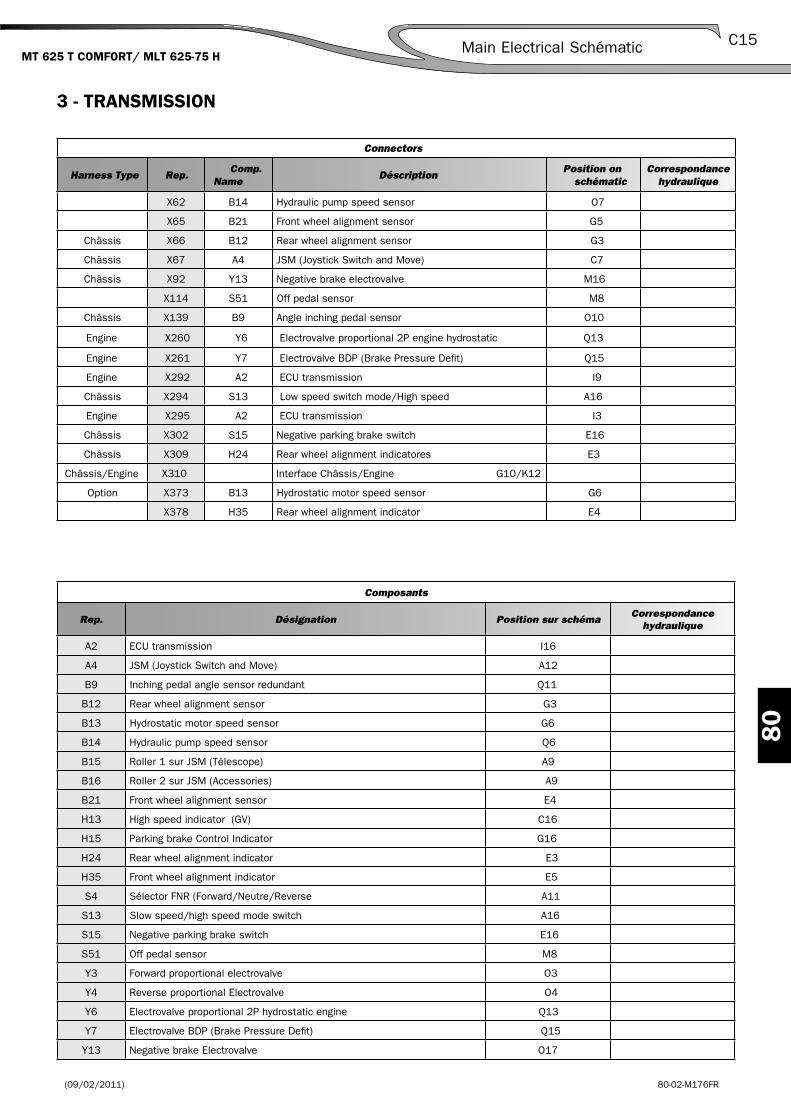
(09/02/2011) 80-02-M176FR
80
C15Main Electrical Schématic MT 625 T COMFORT/ MLT 625-75 H
3 - TRANSMISSION
X62 B14 Hydraulic pump speed sensor O7
X65 B21 Front wheel alignment sensor G5
Châssis X66 B12 Rear wheel alignment sensor G3
Châssis X67 A4 JSM (Joystick Switch and Move) C7
Châssis X92 Y13 Negative brake electrovalve M16
X114 S51 Off pedal sensor M8
Châssis X139 B9 Angle inching pedal sensor O10
Engine X260 Y6 Electrovalve proportional 2P engine hydrostatic Q13
Engine X261 Y7 Electrovalve BDP (Brake Pressure Defi t) Q15
Engine X292 A2 ECU transmission I9
Châssis X294 S13 Low speed switch mode/High speed A16
Engine X295 A2 ECU transmission I3
Châssis X302 S15 Negative parking brake switch E16
Châssis X309 H24 Rear wheel alignment indicatores E3
Châssis/Engine X310 Interface Châssis/Engine G10/K12
Option X373 B13 Hydrostatic motor speed sensor G6
X378 H35 Rear wheel alignment indicator E4
A2 ECU transmission I16
A4 JSM (Joystick Switch and Move) A12
B9 Inching pedal angle sensor redundant Q11
B12 Rear wheel alignment sensor G3
B13 Hydrostatic motor speed sensor G6
B14 Hydraulic pump speed sensor Q6
B15 Roller 1 sur JSM (Télescope) A9
B16 Roller 2 sur JSM (Accessories) A9
B21 Front wheel alignment sensor E4
H13 High speed indicator (GV) C16
H15 Parking brake Control Indicator G16
H24 Rear wheel alignment indicator E3
H35 Front wheel alignment indicator E5
S4 Sélector FNR (Forward/Neutre/Reverse A11
S13 Slow speed/high speed mode switch A16
S15 Negative parking brake switch E16
S51 Off pedal sensor M8
Y3 Forward proportional electrovalve O3
Y4 Reverse proportional Electrovalve O4
Y6 Electrovalve proportional 2P hydrostatic engine Q13
Y7 Electrovalve BDP (Brake Pressure Defi t) Q15
Y13 Negative brake Electrovalve O17
Composants
Rep. Désignation Position sur schémaCorrespondance
hydraulique
Connectors
Harness Type Rep. Comp.
NameDéscription
Position on schématic
Correspondance hydraulique

(09/02/2011)80-02-M176FR
80
C16 Main Electrical SchématicMT 625 T COMFORT/ MLT 625-75 H
Fuses & relays
Rep. Déscription Position on schématic
BF2/M1
F4 ECU transmission + Seat contact + JSM (10A) A3
F10 Sensor + wheel alignment light (2A) A4
BF2/M5
K2 Relay reverse light & buzzer (20A/35A) G13
Splices
Rep. Position on schématic
Ep.9 K11
Ep.10 K10
Ep.13 E7
Ep.14 K18

(09/02/2011) 80-02-M176FR
80
C17Main Electrical Schématic MT 625 T COMFORT/ MLT 625-75 H
Electric Schématic «Transmission»
S
Q
O
M
K
I
G
E
C
A
21 3 4 5 6 7 8 9 10 11 12 13 14 15 16 17 18 19
X300 - Masse M
oteur
X321 - Masse Chassis
X304 - Masse AR Cabine
X303 - Masse AV Cabine
277
279
APC 54
APC 15
323
25 mm2
Y7Y6
B9
B14
Y3 Y4
A2
BF2/M5
A4
B12
H24
B21
H35
Y13
S15
S13BF2/M1
B13
S51
X261X260
X139X62
X292 / C6
X310
X310
X295 / C1
X67
X66
X309
X309
X65
X378
X378
X92
X302
X294
X373
X114
38 31 30
30
68
683176
164
335
79
78
130
160
159
159
27
78163
77
80
38
76
8081
81
277
279
40 38 31 30
162
164
163
167
162
334
335
33733
7
336
334
D O
UT
BO
P
AN
A O
UT
2P
AN
A IN
RP
M M
OT
22 26
20A
NA
IN P
ED
220
20
SE
NS
OR
+
AN
A IN
CH
ING
PE
D1
2117
2121
SE
NS
OR
-16
1616
1717
RP
M P
UM
P +
RP
M IN
MO
T H
YD
R
RP
M P
UM
P -
PW
M O
UT
RE
V -
PW
M O
UT
FO
RW
-
PW
M O
UT
RE
V +
PW
M O
UT
FO
RW
+
BA
T -
D IN
MO
DE
227
2727
BA
T +
RP
M S
EN
SO
R -
RP
M M
OT
+
RP
M IN
MO
T H
YD
R
D IN
FO
RW
D IN
RE
V
26 2422 23
7574
17
7216
73
74 7521 2072 73
129
130
342
342
341
340
340
339
1 21 2
B7B6 B4B5
462 3 1 5
1 2 3 5 72 12 6 1 11
7625342
4 3 8
534
6521
1 2 21
C4
C3 C5 C6 2
1 3
5
12111754632109 8
1
2
A B C
1
2
A B C
1 2
6
2
8
7
9
0
1
5
1
10
10
15
9
5 621 43
2341
EP
10
EP
9EP13
EP14
BDP2PPedal Inching 5Voutput 0.5 to 4.5V
C5
CF
C4
F R
C3
K2
S4
B16B15
-- ++RF N
F10
H15
P
H13
F4
A
-
+
-
+
+ -
1
0
CF
Towards X374-1(page C21)
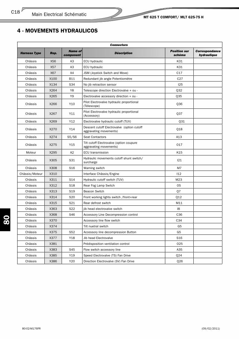
(09/02/2011)80-02-M176FR
80
C18 Main Electrical Schématic MT 625 T COMFORT/ MLT 625-75 H
4 - MOVEMENTS HYDRAULICOS
Châssis X56 A3 ECU hydraulic K31
Châssis X57 A3 ECU hydraulic K31
Châssis X67 A4 JSM (Joystick Switch and Move) C17
Châssis X100 B11 Redundant jib angle Potentiomètre C27
Châssis X134 S34 No jib retraction sensor I25
Châssis X264 Y8 Telescope direction Electrovalve + ou - Q32
Châssis X265 Y9 Electrovalve accessory direction + ou - Q35
Châssis X266 Y10Pilot Electrovalve hydraulic proportional (Télescope)
Q36
Châssis X267 Y11Pilot Electrovalve hydraulic proportional (Accessory)
Q37
Châssis X269 Y12 Electrovalve hydraulic cutoff (TUV) Q31
Châssis X270 Y14Descent cutoff Electrovalve (option cutoff aggravating movements)
Q18
Châssis X274 S5/S6 Seat Contactors A13
Châssis X275 Y15Tilt cutoff Electrovalve (option coupure aggravating movements)
O17
Moteur X295 A2 ECU transmission K15
Châssis X305 S31Hydraulic movements cutoff shunt switch/surcharge
I21
Châssis X308 S16 Warning switch M7
Châssis/Moteur X310 Interface Châssis/Engine I12
Châssis X311 S14 Hydraulic cutoff switch (TUV) M23
Châssis X312 S18 Rear Fog Lamp Switch O5
Châssis X313 S19 Beacon Switch Q7
Châssis X314 S20 Front working lights switch /front+rear Q12
Châssis X315 S21 Rear defrost switch M11
Châssis X363 S22 jib head electrovalve switch I8
Châssis X368 S46 Accessory Line Decompression control C36
Châssis X370 Accessory line flow switch C34
Châssis X374 Tilt nuetral switch G5
Châssis X375 S52 Accessory line decompression Button G5
Châssis X377 Y18 Jib head Electrovalve S16
Châssis X381 Prédisposition ventilation control O25
Châssis X383 S45 Flow switch accessory line A35
Châssis X385 Y19 Speed Electrovalve (TS) Fan Drive Q24
Châssis X386 Y20 Direction Electrovalve (SV) Fan Drive Q26
Connectors
Harness Type Rep.Name of
componentDéscription
Position sur schéma
Correspondance hydraulique

(09/02/2011) 80-02-M176FR
80
C19Main Electric SchématicMT 625 T COMFORT/ MLT 625-75 H
A2 ECU transmission K2
A3 ECU hydraulic K30
A4 JSM (Joystick Switch and Move) A21
B11 Redundant boom angel Potentiomètre C35
B15 Roller 1 sur JSM (Télescope) A18
B16 Roller 2 sur JSM (Accessory) A19
D4 Diode O22
H14 Hydraulic movement cutoff indicator (TUV) O23
H16 Warning indicator M7
H18 Rear fog light control indicator Q4
H19 Beacon indicator control S7
H20 Front/Rear Work lights control indicator Q11
H21 Rear defrost control indicator O12
H22 Boom head electrovalve indicator I8
H31 Security shunt indicator surcharge K22
H52 Accessory line indicator I5
S4 Sélector FNR (Forward/Neutre/Reverse) A20
S5 Seat Contact NO C12
S6 Seat Contact NF C13
S14 Hydraulic cutoff switch (TUV) M24
S16 Warning Switch M6
S18 Rear fog light switch O
S19 Beacon Switch Q7
S20 Work lights switch front/front+rear Q11
S21 Rear defrost switch M11
S22 Head Boom électrovalve switch I8
S31 Switch shunt cutoff movements hydraulic/surcharge I22
S34 NO boom retraction sensor K24
S45 Accessory Flow line Sélector A35
S46 Accessory line decompression control C36
S52 Accessory line décompression button G5
Y8 Electrovalve télescope direction + ou Q32
Y9 Electrovalve accessory direction + ou Q34
Y10 Hydraulic proportional Electrovalve pilotage (Télescope) Q36
Y11 Hydraulic proportional Electrovalve pilotage (Accessoire) Q37
Y12 Hydraulic cutoff Electrovalve (TUV) S22
Y14 Descent cutoff Electrovalve (option aggraviated movements cutoff) S17
Y15 Tilt cutoff Electrovalve (option aggraviated movements cutoff) M17
Y18 Boom head Electrovalve S16
Y19 Speed Electrovalve (TS) Fan Drive Q24
Y20 Electrovalve direction (SV) Fan Drive Q26
Components
Rep. Déscription Position on schématicCorrespondance
hydraulique

(09/02/2011)80-02-M176FR
80
C20 Main Electric Schématic MT 625 T COMFORT/ MLT 625-75 H
Fuses & relays
Rep. Déscription Position on schématic
BF2/M1
F4 ECU transmission + seat contact + JSM (10A) C6
F6 Seat Contact + sensor supply boom angle retract (10A) C6
F7 ECU hydraulic (10A) C6
F8Shunt movements cutoff / boom retract sensor / feed sécurity ECU (10A)
C7
F16 Electrovalve boom head (7,5A) C7
BF2/M5
K2 Reverse light and buzzer (20A/35A) M32
K4 Movements cutoff relay (20A/35A) K28
Splices
Rep. Position on schématic
Ep.5 E29
Ep.6 E13
Ep.8 C20
Ep.11 C18
Ep.12 G26
Ep.15 K33
Ep.24 Q18
Ep.25 C19

(09/02/2011) 80-02-M176FR
80
C21Main Electrical SchématicMT 625 T COMFORT / MLT 625-75 H
S
Q
O
M
K
I
G
E
C
A
21 3 4 5 6 7 8 9 10 11 12 13 14 15 16 17 18 19 20 21 22 23 24 25 26 27 28 29 30 31 32 33 34 35 36 37 38 39 40 41
A
C
E
G
K
M
O
Q
S
I
42
X300 - Masse M
oteur
X321 - Masse Chassis
X304 - Masse AR Cabine
X303 - Masse AV Cabine
279
APC 15
277
APC 54
323
25 mm2
EP15
369
BF2/M1
Y11
S45
S46
Y10Y9Y8Y12
S14
Y14Y18
Y15
A2
S31
S34
S21
S16
S52
S22
S18
S19
S20
A4
S22
Y19 Y20
B11 Angle de flèche 12Voutput 0.5 to 4.5V
X267X266X265X264X269
X305 X134
X315X311
X270X377
X275
X295 / C1
X310
X274
X308
X374
X363
X375
X312
X313
X314
X67
X57
X56
X370
X368 X368
X383
X385
X381
X386
X100
259
262
289
139
138
138
204
196
212
211212
172
362
369
363
370
362
363
364
364
153
197
197
202
201
184
185
202
185
BA
T +
BA
T -
40288
94166
288
94392
39D
IN N
EU
T39
39
427
281
282
83
138
359
169
135
355
83 58
279
277
209
209
207
358
359305
288
600
16694
288
57
208
210
210
211
124
122
120
121
123
126
355
132
131
206
128
370
136392
135
58
19553
195
260
264
263
258
257
357
261
183
48
48
5349 5647 50
284
183 326
8685326
8685326
373
372
371
370
86
373
372
371
370
375 374
125
125
125 137
128
284
281
139
204
201
202
169
456
206
126
120
353
354
259
205
49 56 172
427
360
263
94 357
124
123
310
283
262
264
454
455
86125
1
123
1
12
3
4
4
LM
H
C BOff
21 2211 221
9
51
10
2341
51
9 10
1
6
2
8
7
9
5
1
10
2121
1 2
C3
1 2 12
C7
3 2
1
10
8
7
6
1
1 2 3
10 9
5
1
10 9
5
5
3
2
1
10
5
1
9
51
109
1
26
9 10
3
1
9 10 2 3 6 4 5 7 1 11 128
B
A B
22 15 23 32 06 25 31 34 17 30 07 05 29 08 09
05 16 25 08 06 17 01 12 15 22 10 14 02 03 20 26 13 12 24 16
A3
OU
T L
S 1
IN T
OR
12
IN A
NA
V 1
IN A
NA
V 2
OU
T L
S 1
IN T
OR
1
12 V
B IN
IN T
OR
14
IN A
NA
V 3
IN T
OR
10
IN T
OR
3
IN T
OR
13
OU
T P
WM
7
OU
T P
WM
8
OU
T L
S 2
GN
D P
W
GN
D P
W
IN A
NA
V 8
IN T
OR
16
IN T
OR
15
IN T
OR
8
IN T
OR
5
IN T
OR
6
OU
T P
WM
11
OU
T P
WM
4
OU
T P
WM
9
GN
D A
NA
GN
D P
W
OU
T P
WM
2
OU
T P
WM
3
OU
T P
WM
1
OU
T P
WM
6
OU
T P
WM
5
OU
T P
WM
10
12 V
C
12V
C
33
IN A
NA
V 4
1 2
A B C
1 2
462 3 1 5
EP8EP11
EP5
EP12
Ep.6
EP24
Ep.25
S5
SEAT
S6
F8
F16
F6
F4
F7
A
T+ A+VS
H31
1
0
1
0
H14
1
H21
H16
H22
H52
1
0
0
H18
1
0
1
0
H19
H20
1
0
0
1
NF R
+ +- -
B15 B16
S4
137
Towards EP17(page C17)
Towards X312-9(page C27)
Towrds X91-1(page C33)
Towards X91-2(page C33)
Towards X322-1(page C33)
Towards X322-9(page C33)
Towards EP14(page C17)
Electrical Schématic « Hydraulic Movement »
(09/02/2011)80-02-M176FR
80
C22 Main Electrical Schématic MT 625 T COMFORT / MLT 625-75 H

(09/02/2011) 80-02-M176FR
80
C23Main Electric SchématicMT 625 T COMFORT/ MLT 625-75 H
5 - LIGHTING SYSTEMS / VENTILATION
Cabine 1 X6 E15 Beacon outlet S25/S26
Châssis X11 S28 Wiper handle M36
Châssis X12 Wiper handle O36
Châssis X13 A1 Dashboard unit C39
Châssis X14 S26 / S27 Light handle C13
Moteur X17 B3 Engine oil pressure switch E33
Moteur X18 B5 Thermocontact engine water E34
X20 B35 Clogged air filter G32
Châssis X21 B7 Clogged hydraulic filtre Colmatage E31
Châssis X22 S11 Brake fluid level sensor E30/G30
Châssis X25 M6 Front Wiper Motor Q34
Châssis X26Interconnection chassis harness/front wiper pump
Q31
X27 M5 Front wiper pump S31
Option X28 M8 Rear wiper pump S33
Châssis X31 Rear left light Q10
Châssis X32 Rear right light Q13
Châssis X35 Front light left I11
Châssis X36 Front right light I15
Châssis X37 E7 Minéralogic lighting plate (TUV 25Km/h) Q9
Châssis X38 B1 Back up alarm Q16
Châssis X39 B2 Main Alarm Warning I13
Châssis X40 PER Electric towing outlet Q18
X41 S28 Wiping handle O37
Châssis X46 S30 Cigarrete lighter 05
Châssis X47 S30 Cigarrete lighter O6
Cabine 2 X50 E16 Ceiling light O30
Cabine 1 X59 M7 Rear Wiper motor Q29
Châssis X63 B34 Fuel Gauge E38/G38
Châssis X64 B8 Master cylinder Pressure switch M12/O12
X65 B21 Front wheel alignment Sensor S21
Châssis X66 B12 Rear Wheel alignment sensor Q23
Châssis X67 A4 JSM (Joystick Switch and Move) G37
X103 E19 Boom Work lights A10
X104 E19 Boom work lights A8
Châssis X105 Foot boom work lights Option A4/A7
Châssis X106 Foot boom prédisposition électric option C4
Cabine 2 X10⁷ M4 Roof Wiper Motor M31
Châssis X133 B10 Negative brake info Pressure switch E27/E28
Châssis/Cabine 1 X276 Interface Châssis/Cabine 1 Q25
Châssis/Cabine 2 X277 Interface Châssis/Cabine 2 K29
Moteur X291 B4 Engine water temp. sensor E35
Moteur X292 A2 ECU transmission I32
Moteur X295 A2 ECU transmission I34
Châssis X308 S16 Warning switch A20
Châssis X309 H24 Rear wheel alignment indicator O22/Q22
Connecteurs
Harness Type Rep.Name of
componentDéscription
Position onschématic
Correspondance hydraulique
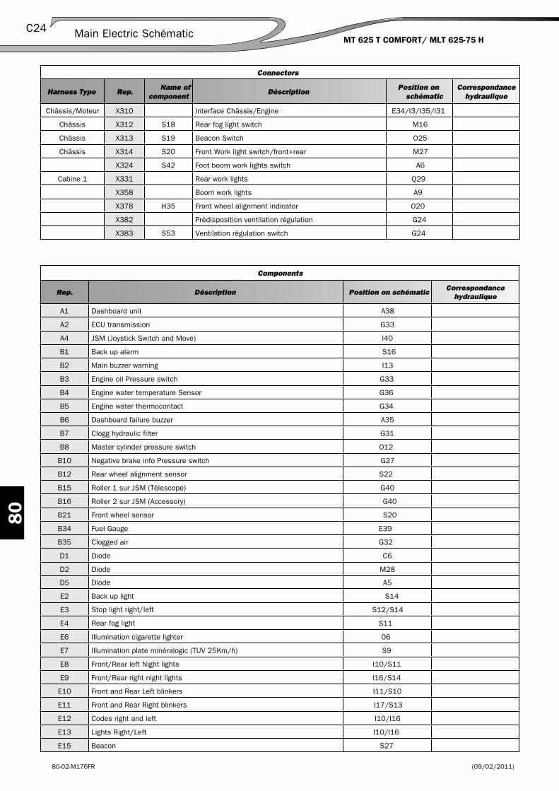
(09/02/2011)80-02-M176FR
80
C24 Main Electric Schématic MT 625 T COMFORT/ MLT 625-75 H
Châssis/Moteur X310 Interface Châssis/Engine E34/I3/I35/I31
Châssis X312 S18 Rear fog light switch M16
Châssis X313 S19 Beacon Switch O25
Châssis X314 S20 Front Work light switch/front+rear M27
X324 S42 Foot boom work lights switch A6
Cabine 1 X331 Rear work lights Q29
X358 Boom work lights A9
X378 H35 Front wheel alignment indicator O20
X382 Prédisposition ventilation régulation G24
X383 S53 Ventilation régulation switch G24
Connectors
Harness Type Rep.Name of
componentDéscription
Position on schématic
Correspondance hydraulique
A1 Dashboard unit A38
A2 ECU transmission G33
A4 JSM (Joystick Switch and Move) I40
B1 Back up alarm S16
B2 Main buzzer warning I13
B3 Engine oil Pressure switch G33
B4 Engine water temperature Sensor G36
B5 Engine water thermocontact G34
B6 Dashboard failure buzzer A35
B7 Clogg hydraulic filter G31
B8 Master cylinder pressure switch O12
B10 Negative brake info Pressure switch G27
B12 Rear wheel alignment sensor S22
B15 Roller 1 sur JSM (Télescope) G40
B16 Roller 2 sur JSM (Accessory) G40
B21 Front wheel sensor S20
B34 Fuel Gauge E39
B35 Clogged air G32
D1 Diode C6
D2 Diode M28
D5 Diode A5
E2 Back up light S14
E3 Stop light right/left S12/S14
E4 Rear fog light S11
E6 Illumination cigarette lighter 06
E7 Illumination plate minéralogic (TUV 25Km/h) S9
E8 Front/Rear left Night lights I10/S11
E9 Front/Rear right night lights I16/S14
E10 Front and Rear Left blinkers I11/S10
E11 Front and Rear Right blinkers I17/S13
E12 Codes right and left I10/I16
E13 Lights Right/Left I10/I16
E15 Beacon S27
Components
Rep. Déscription Position on schématicCorrespondance
hydraulique

(09/02/2011) 80-02-M176FR
80
C25Main Electrical Schématic MT 625 T COMFORT/ MLT 625-75 H
E16 Roof Ligh O29
E19 Boom work lights A8/A10
H1 Batery charge indicator A24
H2 Active negative brake indicator A25
H3 Engine oil pressure indicator A25
H4 Engine water temp. indicator A26
H5 Hydraulic filter clogging indicator A27
H6 Container brake fluid level indicator A28
H7 High beam A28
H8 Turn signal indicator A29
H9 Fault indicator ECU downgrade mode A30
H10 Réserve fuel Indicator A31
H16 Warning indicator C21
H18 Rear fog light control indicator O16
H19 Beacon Indicator control O24
H20 Work light front/rear indicator control O27
H24 Rear wheel alignment indicator Q22
H25 General Fault indicator A32
H26 Clogged air filter indicator A32
H27 Préheating indicator A33
H28 Forward indicator A34
H29 Neutral indicator A35
H30 Reverse indicator A35
H35 Rear wheel alignment indicator Q20
H42 Foot boom light control indicator C6
H53 Regulation ventilation control indicator control I25
M3 Beacon Motor S27
M4 Roof Motor wiper O31
M5 Front wiper pump motor S31
M6 Front motor wiper S35
M7 Rear wiper Motor S29
M8 Rear wiper pump S32
P1 Hourmeter unit A39
P2 Diesel gauge unit C36
PER Electric tow outlet S20
S4 Sélector FNR (Forward/Neutre/Reverse) I39
S11 Brake fluid level sensor G29
S16 Warning switch A20
S18 Rear fog light switch M16
S19 Beacon switch M24
S20 Front/front+rear work lights switch M26
S25 Roof light switch control O29
S26 Horn control A16
S27 Illumination handle C15
S28 Wiper handle S38
S29 Roof wiper Handle M32
S30 Cigarette lighter control Commande 07
S42 Foot boom light switch A6
Components
Rep. Déscription Position on schématicCorrespondance
hydraulique

(09/02/2011)80-02-M176FR
80
C26 Schémas de principe électriqueMT 625 T COMFORT/ MLT 625-75 H
Splices
Rep. Position on schématic
Ep.18 E39
Ep.39 M32
Fuses & relays
Rep. Déscription Position on schématic
BF1/M1
F44 Cabine fuse box (+BAT) (50A) I5
BF2/M1
F1 Feed dashboard (+apc) (7,5A) M5
F4 ECU transmission + seat contact + JSM (10A) M5
F5 Cigarette lighter + info autoradio (10A) M5
F9 Feed K2 + K3 (reverse light + reverse buzzer + stop light) (5A) M5
F10 Sensor + lamp wheel alignment (2A) M5
F11 Central blinker (feed + APC) (15A) M5
F12 Rear fog light switch K5
F13 Boom work lights switch (15A maxi) K5
F14 Beacon (7,5A) K5
F17Rear wiper control + Roof wiper + rear wiper (15A)
K5
F18 Front wiper control + windshield washer (15A) K5
F20 Heater (20A) K5
BF2/M2
F21 Left Night lights feed + cigarette lighter light feed (3A) G5
F22Right night light feed + Hydrauilc pilot illumination button + dashboard illumination (3A)
G5
F23 Feed codes (15A) G5
F24 Light feed (15A) G5
F25 Right blinkers feed (7,5A) G5
F26 Left blinkers feed (7,5A) G5
F31 Illumination Handle (25A) E5
F32 Warning + centrale blinking (alim+bat) (15A) E5
F34 Horn + roof light + dashboard (7,5A) E5
F37 Rear Motor wiper (+perm) (10A) E5
F38 Front Motor wiper (+perm) (15A) E5
BF2/M3
K10 Air condition time relay A17
BF2/M4
K8 Centrale blinker C18
S53 Regulation ventilation control switch G25
Components
Rep. Déscription Position on schématicCorrespondance
hydraulique
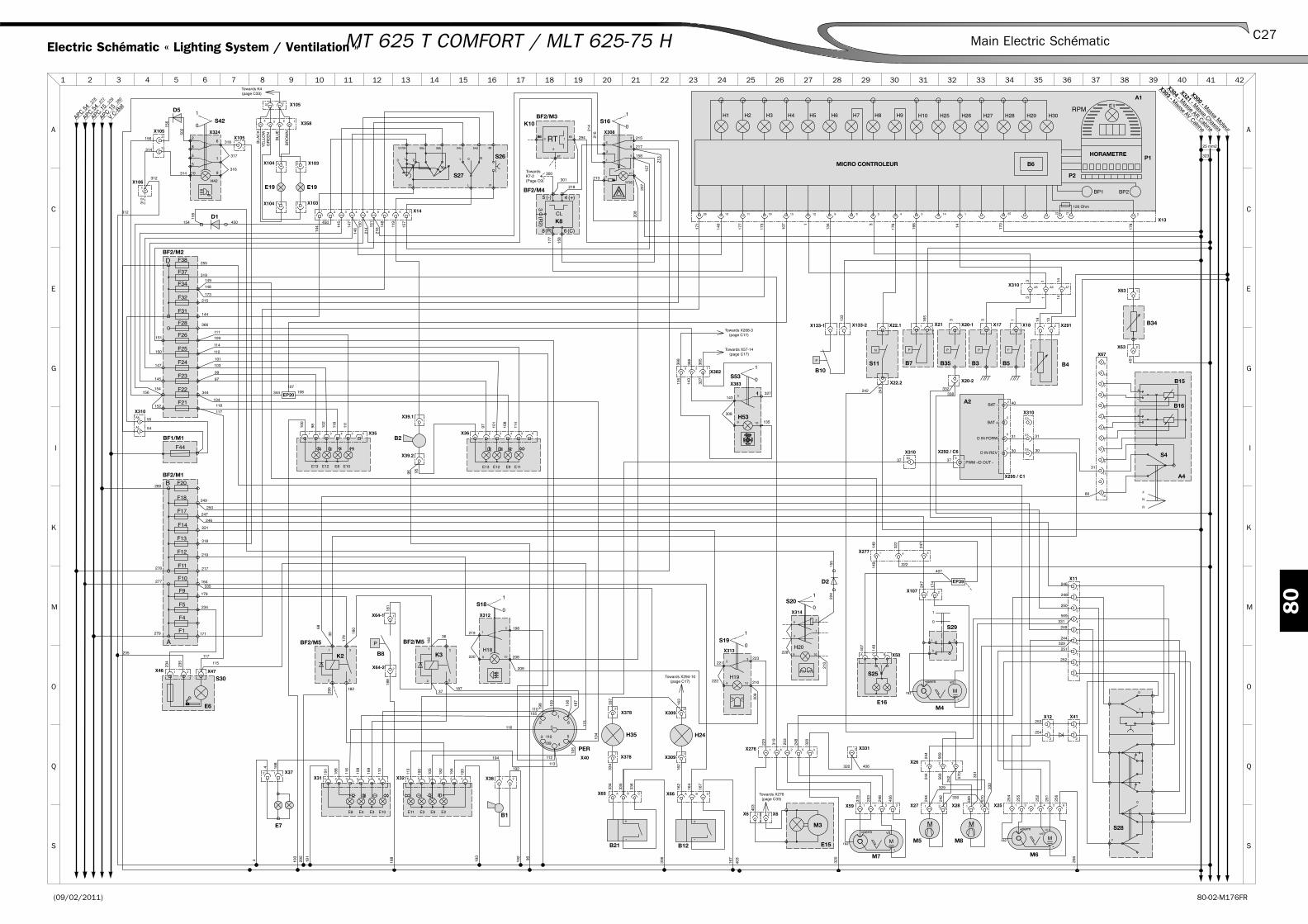
(09/02/2011) 80-02-M176FR
80
C27Main Electric SchématicMT 625 T COMFORT / MLT 625-75 H
S
Q
O
M
K
I
G
E
C
A
21 3 4 5 6 7 8 9 10 11 12 13 14 15 16 17 18 19 20 21 22 23 24 25 26 27 28 29 30 31 32 33 34 35 36 37 38 39 40 41
A
C
E
G
K
M
O
Q
S
I
42
X300 - Masse M
oteur
X321 - Masse Chassis
X304 - Masse AR Cabine
X303 - Masse AV Cabine
APC 54
27827
727
928
0
APC 54
APC 15
APC 15
V C-B
at
323
25 mm2
336
+
-
BF2/M3
H24
B12M5
S20
M3
E15
S19
M6M7
M4
S29
E16
S42
BF2/M4
S16
B34
B7S11B10
E19 E19
S26
S27
B1
E7
S30
S18
B8
BF2/M5BF2/M5
A1
MICRO CONTROLEUR
HORAMETRE
B4B5B3B35
BF2/M1
BF2/M2
D1
B2
S53
H53
BF1/M1
S28
A4
A2
PER
S25
E6
K2
S4
K10
P2
B6P1
K3
D2
B15
B16
K8
M8
D5
H35
B21
X106
X309
X309
X66
X27
X26
X314
X6X6
X313
X25X59
X276
X107
X50
X277
X308
X63
X63
X21X22.1X133-1 X133-2
X104 X103
X104 X103
X14
X36
X40
X382
X383
X35
X105
X38X31 X32X37
X46 X47
X312
X64-2
X64-1
X13
X291X18X17X20-1
X20-2
X310
X39.2
X39.1
X11
X41X12
X331
X310
X105
X358
X67
X295 / C1
X292 / C6
X310
X324X105
X22.2
X28
X310
X378
X378
X65
312
312
312
314
10
51
9
62
8
5
314
317
316
318 BR
OW
N
BLU
E
YE
LLO
W G
RE
EN
BLA
CK
157
148
216
214
14614
4 119
101
147
97
145
100
98 102
111
150
151450
192
194
190
191
189
110
116
199
113
193
105
194
182
1684 16
8
118
235117
235
234
187
188
188
37
181
180
179
180
30
68
182
36
295
280
278
279
277
318
217
164335
171
247
221
249
250
246
234
219
179
215
173
148
149
255
319
144
366
114
111
147 103
145
99
150 112
151 109
154156
156
152
115
117
118
155
450154
55
54
162
167
167
163
164
162
242
242
244
244
403
403
223
256
251
252
254
255
256
248
253
319
406
100
192
105
116
112
113
109
110
110
199
115
104
105
193
191
4
198 18
7
190
295
96
253
248
320
320
319
320 406
228
210221
222
223
210
322
322
330
329
247
174
407
149
407
149
149
247
198219
220
209
209
208
244329
246
248
250
249
251
252
253
254
155
224
31
68
294
107
207
157
213158
158
177
177
218
300
301
208
215
173
216
214
146
217
171
170
178
451
166
165
176
242327
135
308
143
243
134
133
97 101
108
114
368
366
365
327
143
135
14
31
1413
1413
1314133
BAT +
37
332338
37
BAT - 40
30D IN REV
PWM -/D OUT -
31D IN FORW
30
31
213
9596
570
570
569
331
332
569
569
569331
244
156
502
107108344344
104
334
336
337
335
334
CBA
2
1
1 2
1
3
109
62
21
9 10
15
6251 43
52
1 4 3 2
6
4
3
1 2
1 2
C BA
1 3
2
1
21
8 14 25 22 2126 2349
9
10
10
11 1518 1512
A5 A6 A7
21
1 4
7
8
9
6
5
4
3
2
1
1
22
1
2
9
10
6
4
5
7
1
2
3
8
11
9
2
2
6
7
12
C3
C6
C5
2
1
1
1
49
3130
57/58
76
54s
L
56a 56b
543
65
5
1
1
2 3 4321 5 6
54d
8 92
2
1 23 5 1 624 6 5 3 1 2 4
2 1
4
21 1
9
15
10
1
2
3
55
31
2
3
A1
A8
2 1
2 14 3
2 2
1 1
1
2
3
87
86 85
1
2
5
6
7
3
8
10
1 2
1 2 3
1
2
B3
CBA
2
1
123
EP39
EP20
F13
F11
F1
F4
F20
F5
F12
F18
F14
F17
F9
F10
A
B
F32
F34
F31
F28
F24
F23
F25
F26
F22
F21
D
F44
F38
F37
RT86
+
-
M
0
1
0
1
H200
1
H19
vit2
Mraz
-
vit 1+perm+perm vit
-raz M
+perm vit
-raz M
0
1
1
0
H42
5
8
3
4
(R2)
(-)
(R)
(+)
CL
6 (C)
0
1
H16
PN
P
R0 1 2 L 0
E11E9E12E13E13 E8 E10E12
1
2
3
4
5
67
E8
STOP
E10E3E4 E2E9E3E11
STOP
0
1
H18P
H25 H26 H27 H28 H29 H30
E1
BP2BP1
RPMH9H7 H8H6H5H4 H10
120 Ohm
H3H2H1
t°PP
1
0
F
0
N
F
R
++
-
-
M
Towards X294-10(page C17)
Towards X276(page C33)
Towards K7-2(Page C9)
Towards K4(page C33)
Towards X268-3(page C17)
Towards X57-14(page C17)
Electric Schématic « Lighting System / Ventilation »

(09/02/2011)80-02-M176FR
80
C28 Main Electric Schématic MT 625 T COMFORT / MLT 625-75 H

(09/02/2011) 80-02-M176FR
80
C29Schémas de principe électriqueMT 625 T COMFORT/ MLT 625-75 H
6 - OPTIONS
Châssis X29 Heater Ventilator / air condition E38
Châssis X91 Boom head electrovalve Option Q20
Châssis X93 A7 Autoradio feed E13
Châssis X94 A7 Speaker autoradio E16
Châssis X95 Option Air condition M35
Châssis X105 Foot boom work lights Option K25
Châssis X106 Foot boom prédisposition électric M24
X153 A10 Bloc condenser O35
X154 A10 Bloc condenser O36
Châssis X155 A9 Air condition harness option G35
X166 Y17 Head boom Electrovalve Q19
Châssis X204 HPD Right speaker C14/C16
Châssis X205 HPG Left speaker E16
Châssis X268 Accessory shunt M18
Option X274 S44/M11 Seat Contactor C26
Châssis/Cabine 1 X276 Interface Châssis/Cabine 1 M9/Q8
Châssis/Cabine 2 X277 Interface Châssis/Cabine 2 M14/Q15
Châssis X285 M9 Ventilator E38
Châssis X286 S24 Ventilation control E37
Châssis X305 S31Cutoff movements hydraulic switch shunt/surcharge
I19
Châssis X308 S16 Warning switch Q4
Châssis/Moteur X310 Interface Châssis/Engine G5/M29
Châssis X311 S14 hydraulic cutoff switch (TUV) I16
Châssis X312 S18 Rear fog lamp switch M4
Châssis X313 S19 Beacon Switch I4
Châssis X314 S20 Work light switch front/front + rear I7
Châssis X315 S21 Rear window defrost switch I14
Cabine 2 X316 R6 Rear window defrost M15/O15
Châssis X322 S12 Forward forced switch I22
X326 S23 Air condition control switch C35
X327 B18 Air condition evaporator thermostat E34
Cabine 1 X330 E18 Work lights front, right and left O10
Cabine 1 X331 E17 Work lights rear, right and left M8/O8
X360 S22 Line accessory lock switch 018/O27/Q19
X362 S32 Electric boom prédisposition switch O25
X363 S22 Line accessory lock switch O20
Châssis X365Interconnection harness chassis/blue headlights harness poultry
G7
Option X367 S43 Blue lights poultry switch E10
Option X372 S33 Accessory lock switch M20
Connectors
Harness Type Rep.Name of
componentDéscription
Position on schématic
Correspondance hydraulique

(09/02/2011)80-02-M176FR
80
C30 Main Electrical SMT 625 T COMFORT/ MLT 625-75 H
A3 ECU hydraulic G20
A7 Autoradio G15
A9 Cooling Block C38
A10 Condenser Block Q36
B17 Evaporator probe G33
B18 Evaporateur cooling Thermostat E33
B20 Binary Pressureswitch (HP/BP) climate Q36
D1 Diode I10
D2 Diode I10
D3 Diode K34
D4 Diode K15
E17 Rear right and left working lights O8/O9
E18 Front right and left working lights O18/O12
E20 Poultry blue lights O13
H12 Forced forward indicator K22
H14 Hydraulics movements cutoff indicator (TUV) K17
H16 Warning indicator S5
H18 Control indicator O4
H19 Bacon control indicator K4
H20 Working lights front/rear control indicator K7
H21 Rear window defrost control indicator K12
H22 Accessory lock indicator O20
H31 Security surcharge shunt indicator K20
H32 Electric boom prédisposition indicator O25
H36 Poultry blue light indicator G10
HPD Right speaker C18
HPG Left speaker C18
M9 Heater moto fan G37
M10 Air condition condenser Moto fan Q35
M11 Air seat Motor E26
R6 Rear window defrost O15
S12 Forced forward switch option I23
S14 Hydraulic cutoff switch I17
S16 Warning switch Q4
S18 Rear fog lamp switch M4
S19 Beacon Switch I4
S20 Front/front+ Rear working lights switch I7
S21 Rear window defroster I12
S22 Accessory Line Lock Switch O20
S23 Air condition control switch C32
S24 Heater switch control E36
S31 Hydraulic movements /surcharge cutoff shunt switch I20
S32 Electric boom prédisposition switch M25
S33 Accessory lock switch M20
S36 Poultry blue lights switch E10
S44 Air seat control C26
Components
Rep. Déscription Position on schématicCorrespondance
hydraulic
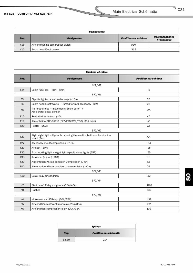
(09/02/2011) 80-02-M176FR
80
C31Main Electrical SchématicMT 625 T COMFORT/ MLT 625-75 H
Fusibles et relais
Rep. Désignation Position sur schéma
BF1/M1
F44 Cabin fuse box (+BAT) (50A) I5
BF2/M1
F5 Cigartte lighter + autoradio (+apc) (10A) C5
F6 Boom head Electrovalve + forced forward accessory (10A) C5
F8Tilt neutral feed + movements Shunt cutoff + Accelerator pedal sensor
C5
F15 Rear window defrost (10A) C5
F19 Alimentation BUS-BAR C (F27/F28/F29/F30) (30A maxi) A5
F20 Heater (20A) A5
BF2/M2
F22Right night light + Hydraulic steering illumination button + illumination board (3A)
G4
F27 Accessory line décompression (7,5A) G4
F29 Air seat (10A) E5
F30 Front working light + night lights/poultry blue lights (25A) E5
F35 Autoradio (+perm) (10A) E5
F39 Alimentation K6 (air condition Compressor) (7,5A) E5
F40 Alimentation K5 (air condition motoventilator ) (20A) C5
BF2/M3
K10 Delay relay air condition I32
BF2/M4
K7 Start cutoff Relay / digicode (20A/40A) K26
K8 Flasher I39
BF2/M5
K4 Movement cutoff Relay (20A/35A) K38
K5 Air condition motoventilator relay (20A/35A) I32
K6 Air condition compressor Relay (20A/35A) I30
Splices
Rep. Position on schématic
Ep.39 Q14
Y16 Air conditioning compressor clutch Q30
Y17 Boom head Electrovalve S19
Components
Rep. Désignation Position sur schémaCorrespondance
hydraulique

(09/02/2011)80-02-M176FR
80
C32 Main Electric Schématic MT 625 T COMFORT/ MLT 625-75 H

(09/02/2011) 80-02-M176FR
80
C33Main Electrical SchématicMT 625 T COMFORT / MLT 625-75 H
S
Q
O
M
K
I
G
E
C
A
21 3 4 5 6 7 8 9 10 11 12 13 14 15 16 17 18 19 20 21 22 23 24 25 26 27 28 29 30 31 32 33 34 35 36 37 38 39 40 41
A
C
E
G
K
M
O
Q
S
I
42
X300 - Masse M
oteur
X321 - Masse Chassis
X304 - Masse AR Cabine
X303 - Masse AV Cabine
323
25 mm2
APC 54
27827
727
928
0
APC 54
APC 15
APC 15
V C-B
at
X361
BF1/M1
S18
S16
S21
S44
S19S20 D2
R6
S24
M9
A9
B17
S23
B18
BF2/M3 K10
B20M10
A10
D3K5K6BF2/M5 BF2/M5
A7
Y16
BF2/M4
S14
K4
BF2/M5
S31
S22
S33
Y17
S12
BF2/M1
BF2/M2
D1
S32
K7
BF2/M4
D4
E18
K9
S36
E20E20
M11
E17E17 E18 E18
X310
X312
X308
X315X313
X314
X316-1
X316-2
X277
X286
X29X327
X326
X155
X95
X154
X153
X310
X30
X311 X305
X268
X363
X166
X91
X322
X362
X106
X204-2
X205-1 X205-2
X204-1
X93 X94
X277
X360
X367
X365
X274
X372X276
X331
X331
X330
X330
X276
55
54
220
209
209
207
208
208
210222
5
109
1
210
211228
227
550
552
106
551
156
106
156
550
26
9 10
31 229
225
224 155
290
231
233
303
302
237
226
553
226
558
313
280
278
277
35277
279
55
419
419
292
450
154
9
1
552
322
289
306
306
5
10
1
2
5
6
7
38
10
322
408
230
230
308
312
305
306
305
310
5 1
9 10
1 501
500
313
312
313
312
389
430
8
431
432
432
431
389
88
389
293
387
386
385
C
430
388
430
292
430
301
8586
87
15 294
390
324
389
388
325
301
1
2
3
5
313 306
303
86
28
325
297298299
15
28302
8
5 4
3
2
1
30
87a8785
861
2
3
45
30
87a8785
86
324
299
153
10
15
9
7
8
26
212
10
15
9136
288
289
288
288
311
312358
291283
10
15
9
211
1
109
15
232
231230
212
2
35
1
54
1
238
239
240
241
240
238
237
241
239
236
233
1
2
3
45
30
87a8785
86
1
109
15
553
552
553
BROWN
BROWN
554
555
556
555
555
555
553
553
551
559
558
308
143
143
1
75
10 9
15
10 9
327
135
327
13513535
135
229
225
320
321
229
229
320
320
2 4
1 3
BR
OW
N
BR
OW
NB
LUE
BLU
E
A1
A8
4
2
4 3 2 1
2 1
12
A4
1 2
1 2
21
1
3
2
2
3
1
5 6
21
43 2 1
3
1 2 3
4 5
1
2
2 4
31
4 8
3 7
EP39
F44
0
1
H18
0
1
H16
H21
1
0
1
H19
0
H20
1
0
1
0
H14
1
0
H31H12
1
0
F6
F8
F15
F5
F19
F20
A
B
F35
F39
F40D
F30
F29
F27
C
LOff
B M
H
Black
Black
Black
Green
Red
Blue
3
2
1RT
Sup
ply
+12
V
+
-
(C)6
K8
CL
(+)
(R)
(-)
(R2)
4
3
8
5
H22
0
1
H32
+
-
BROWN
BLUE
T°
-
+
HP
G
+
-
HP
D
31ALIM-AUTO
5 7
2 4 6 8
31HP-AUTO
5 7
2 4 6 8
+ B
AT
+ A
PC
EC
C
H36
1
0
M
0
1
0
1
H33
F22
Towards K5-2(page C33)
Towards X312-9(page C27)
Towards X56-22(page C21)
Towards X57-33(page C21)
Towards X382-2(page C71)
Electric Schématic « Options »

(09/02/2011)80-02-M176FR
80
C34 Main Electrical Schématic MT 625 T COMFORT / MLT 625-75 H

(22/10/2010) 70-02-M176FR
70
B1 Main Hydraulic Schematic
pagesMLT 625-75 H
Légend . . . . . . . . . . . . . . . . . . . . . . . . . . . . . . . . . . . . . . . . . . . . . . . .B3
Schématic . . . . . . . . . . . . . . . . . . . . . . . . . . . . . . . . . . . . . . . . . . . . . .B5
–
–

(22/10/2010)70-02-M176FR
70
B2 Main Hydraulic Schématic

(22/10/2010) 70-02-M176FR
70
B3Main Hydraulic SchématicMLT 625-75 H
HYDRAULIC SCHEMATIC LEGEND (MLT 625-75 H)
Rep. DéscriptionPosition on
schématicCaractéristiques (Options)
BA BLOCK FEED + ACCUMULATOR ( K15
BCMA AGGRAVATING MOVEMENT CUT OFF BLOCK Q27
BMHP PROPORTIONAL HYDRAULIC MANIPULATEUR BLOCK Q24
CA SUCTION STRAINER S11
CAR ANTI-RETURN FLAP S12
D DISTRIBUTOR M37
D3 3 POSITION STEERING DISTRIBUTOR A13
- POSITION 1 : TURNING SHORT A14
- POSITION 2 : FRONT WHEEL STEERING A14
- POSITION 3 : CRAB STEERING A14
EVTF (O) HEAD BOOM ÉLECTROVALVE G41 OPTION
FDAR REAR FRONT DISC C18
FDAV FRONT BRAKE DISC C4
FR RETURN FILTRE Q14
M THERMIC ENGINE KUBOTA V3307 DI-T (TURBO) O2
- IDLING 895 ±25 Tr/min
- SYSTEM RATED LOAD 2600 Tr/min
- HIGH IDLE 2800 Tr/min
MC MASTER CYLINDER A8
MH HYDROSTATIC MOTOR A7
MHRV HYDRAULIC MOTOR REGULATION VENTILATION K8
P HYDRAULIC PUMP O4
PAAV FRONT ACCESSORY OUTLET G37
PAAV (O) FRONT ACCESSORY OUTLET E35 E40 OPTION
PDD DYNAMIC STEERING PUMP I15
PH HYDROSTATIC PUMP O11
PP PRESSION OUTLET E8/K15/O25
PRF (O) RETURN RELEASE OUTLET M40 OPTION
R PRINCIPAL HYDRAULIC TANK S15
R1 SECONDARY HYDRAULIC TANK Q19
RF COOLER K12
RLF BRAKE FLUID TANK A8
VAI(O) ISOLATION VALVE OPTION
VC COMPENSATION CYLINDER E30 DE 115x60 C310
VE BALANCING VALVE E32 /G30/I28/I37
VDAR REAR STEERING CYLINDER C16
VDAV FRONT STEERING CYLINDER C6
VI TILT CYLINDER G27 DE 125x65 C 396
VL LIFT CYLINDER I26 DE 120x70 C 1100
VT TÉLESCOPING CYLINDER I35 DE 70x45 C 2200
VVT (O) DECK LOCK CYLINDER E38 DE 60x45 C 183 - OPTION
Y3 FORWARD ÉLECTROVALVE PROPORTIONAL O7
Y4 REVERSE ÉLECTROVALVE PROPORTIONAL O6
Y6 ÉLECTROVALVE PROPORTIONAL 2P HYDROSTATIC MOTOR SAUER (PCOR)
C8
Y7 ÉLECTROVALVE BPD (BRAKE PRESSURE DEFEAT) C9
Y8 ÉLECTROVALVE TÉLESCOPING SENS + OU - K19
Y9 ÉLECTROVALVE ACCESSORY SENS + OU - K19

(22/10/2010)70-02-M176FR
70
B4 Main Hydraulic Schématic MLT 625-75 H
HYDRAULIC SCHEMATIC LÉGEND (MLT 625-75 H)
Rep. DéscriptionPosition on
schématicCaractéristiques (Options)
Y10 ÉLECTROVALVE STEERING HYDRAULIC PROPORTIONAL(TÉLESCOPING)
K18
Y11 ÉLECTROVALVE STEERING HYDRAULIC PROPORTIONAL (ACCESSORY)
K18
Y12 ÉLECTROVALVE HYDRAULIC CUTOFF (TUV) K17
Y13 ÉLECTROVALVE NEGATIVE BRAKE M19
Y14 ÉLECTROVALVE PROPORTIONAL CUTOFF DESCENT Q28
Y15 ÉLECTROVALVE TILT CUTOFF S28
Y17 ÉLECTROVALVE BOOM HEAD G39 OPTION
Y18 ÉLECTROVALVE PROPORTIONAL RAISE CUTOFF Q28
1 r = 1.16 x RPM O3
2 télescope retract-4b K20
3 télescope release-4a K20
4 locking accessory-3b K20
5 locking accessory-3a K20
6 lift-1b Q30
7 descent-1a Q31
8 breakout-2a S32
9 discharge-2b S30
10 dynamic priority flow valve O27
11 lift O30
12 tilt O32
13 accessory O34
14 télescoping O36
15 (90l/min) descent K30
16 (90l/min) lift K16
17 (90l/min) breakout K32
18 (90l/min) discharge K32
19 (90l/min) unlocking accesory K34
20 (90l/min) locking accessory K34
21 (90l/min) télescope release K35
22 (90l/min) retracted télescope K36
23 security valve * O28
* (cuts all the aggravating movements when the machine have reached its limits of stability)

70
(22/10/2010) 70-02-M176FR
B5Main Hydraulic Schématic MLT 625-75 H
S
Q
O
M
K
I
G
E
C
A
21 3 4 5 6 7 8 9 10 11 12 13 14 15 16 17 18 19 20 21 22 23 24 25 26 27 28 29 30 31 32 33 34 35 36 37 38 39 40 41
A
C
E
G
K
M
O
Q
S
I
42
V2V1
4
T
P
2
3
1
V1
V2
V2
V1
11 cm³/tr31 cm³/tr
V2
V1
10μm
4.5 bar2 bar
VA
90l/min125μm
3 bar
4 bar
8 cm³/tr
Y3Y4
L2
M4
M5
M3 MAA
B
MBS L1
45 cm³/tr
12 cm³/tr 400 bar
400 bar
P2
P1
C2
A2A1C1
B1 B2
V2 V1
C2
C3
P1P2
C4
C1
Y17
160cm³/tr
140 bar
200bar
200bar
LSP T
RL
80 cm³/tr
A
B
L2
M5
L1
Y7
Y6
M4
min max
8 bar
245 bar245 bar
270 bar
210 bar
210 bar
235 bar
4A 4B3A 3B2A 2B1B1A
T
P
PLS 1b
1a
2b
2a
3b
3a
4b
4a
180 bar245 bar
Y15
Y18
Y14
P P
L+T
L+
T
L- L-
T+ T+
T- T-
PP
DR
EF
RVE
Pp
Pin
IN
PsahrAC
0.32 Litre15 bar
T+
T-
A-
A+
SAHR
T
PPC
Y11
Y10
Y9
Y8
Y12
Y13
PP VVT(O)
VC
BCMA
PDD
MC
RF
R1
R
D
BA
BMHP
MH
PH
VL
VI
VT
M
RLF
P
VE
VE
VE
VE
CA
CAR
FR
MHRV
F00AF00B
B2 B1
PRF(O)
FDAV
VDAR
VDAV
FDAR
PAAV(O) PAAV(O)
EVTF(O)
PAAV
VAI(O)
PO
NT
AR
RIE
RE
PO
NT
AV
AN
T
P
3 2 1D3
TA B
3 1
3 2 1ARAV
2
160b +50
1
2
3
4
5
6
7
8
9
15 17 19 21
16 18 20 22
10 23 1211 13 14

70
(22/10/2010)70-02-M176FR
B6 Main Hydraulic Schématic