MANHOLE BRACE MGF TECHNICAL FILE · MANHOLE BRACE MGF TECHNICAL FILE 3.1.1 Issue 4 Description...
16
[email protected] MANHOLE BRACE MGF TECHNICAL FILE 3.1.1 Issue 4 Description Simple to assemble, four sided, hydraulic bracing frame system designed to be used with steel trench sheets or sheet piles to brace small cofferdams for the safe installation of manholes, pits and tanks. The range comprises seven sizes of hydraulic bracing frame legs ranging in length from 1.4m to 6.0m and is normally installed using either excavators or cranes. Fabricated from grade S355 SHS steel box sections the legs are assembled to form a frame using simple corner pin and retaining clip assemblies. Each leg contains a hydraulic ram with between 630mm and 1300mm of stroke. Connecting the rams (via hydraulic hoses) to an MGF hydraulic pump unit containing hydraulic shoring fluid allows the leg lengths to be quickly and easily adjusted to suit the excavation dimensions. Once the frames are fully assembled and located at the correct line and level, the rams are pre-loaded against the trench sheets using a hydraulic pump. Pre-loading of the legs ensures the frame cannot slip and minimises the extent of potential ground movements. Self sealing quick release valves and mechanical isolation valves ensure that the hydraulic ram pressure cannot be accidently released once installed. Handling and restraining points are provided on each leg to assist assembly / removal and to allow the brace to be supported off MGF restraining chains attached to the trench sheets by hooks. MGF can supply the systems with a full range of suitable handling and restraining chains, Edgesafe edge protection panels, Laddersafe access platforms and GRP or wooden pole ladders, Davitsafe retrieval / fall arrest systems, hydraulic pump installation kits (including bio-degradable shoring fluid and hydraulic hoses) and confined spaces regime equipment. Manufactured and designed in accordance with BS EN 14653:2005 PARTS 1 and 2 Manually operated Shoring Systems for Groundwork Support and BS 5975 (2008) Code of Practice for Temporary Works Procedures and the Permissible Stress Design of Falsework. Product Notes 1. Manhole brace should only be installed and removed by competent persons in accordance with a site specific detailed design & installation sequence and MGF installation guidelines. 2. Installation is normally carried out by lowering either the assembled frame or individual legs (dependant upon lifting capacity of excavator / crane) to the correct installation level and once the frame is fully assembled, pre- loading each leg in turn to ensure that the frame is pressed firmly against the trench sheets and cannot slip. Max pre-load pressure of 100Bar (1500psi) must not be exceeded. 3. Restraining chains are hung off the trench sheets and attached to the legs to assist assembly / removal of the frame and ensure vertical support is provided at all times. All the supplied restraining chains should be installed (min. 2 per leg) and adjusted to ensure an even vertical load distribution. Restraining chains should never be used for lifting nor solely relied upon to suspend loads above personnel. 4. Ensure all hydraulic ram isolation valves are closed and all corner pins in place and secured using the retaining clips provided prior to commencing works. 5. Individual brace legs should be visually inspected for damage, excessive deflection or loss of ram pressure prior to entering the excavation. 6. Legs should always be installed square and plumb to the excavation walls ensuring contact with all the inward facing trench sheet pans. If this is not possible any gaps must be securely packed by using hardwood wedges prior to final pre-loading of the hydraulic rams. 7. Safe access/egress, edge protection (for personnel) and barrier protection (for plant) should always be considered. 8. Prior to removal of systems all hydraulic rams must be released and retracted to avoid the need for excessive extraction forces and to avoid damaging corner joints. 9. No matter how much care is taken during the installation and removal of hydraulic bracing systems some ground movement will occur in the areas immediately surrounding the excavation. Great care must be taken when specifying these systems for use adjacent to existing structures and services.
Transcript of MANHOLE BRACE MGF TECHNICAL FILE · MANHOLE BRACE MGF TECHNICAL FILE 3.1.1 Issue 4 Description...
MAN
HO
LE B
RAC
EM
GF
TEC
HN
ICAL
FIL
E
3.1.1Issue 4
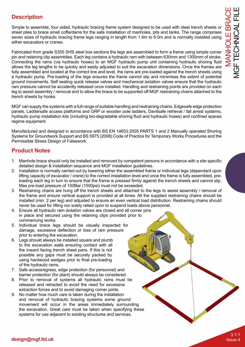
DescriptionSimple to assemble, four sided, hydraulic bracing frame system designed to be used with steel trench sheets or sheet piles to brace small cofferdams for the safe installation of manholes, pits and tanks. The range comprises seven sizes of hydraulic bracing frame legs ranging in length from 1.4m to 6.0m and is normally installed using either excavators or cranes.
Fabricated from grade S355 SHS steel box sections the legs are assembled to form a frame using simple corner pin and retaining clip assemblies. Each leg contains a hydraulic ram with between 630mm and 1300mm of stroke. Connecting the rams (via hydraulic hoses) to an MGF hydraulic pump unit containing hydraulic shoring fluid allows the leg lengths to be quickly and easily adjusted to suit the excavation dimensions. Once the frames are fully assembled and located at the correct line and level, the rams are pre-loaded against the trench sheets using a hydraulic pump. Pre-loading of the legs ensures the frame cannot slip and minimises the extent of potential ground movements. Self sealing quick release valves and mechanical isolation valves ensure that the hydraulic ram pressure cannot be accidently released once installed. Handling and restraining points are provided on each leg to assist assembly / removal and to allow the brace to be supported off MGF restraining chains attached to the trench sheets by hooks.
MGF can supply the systems with a full range of suitable handling and restraining chains, Edgesafe edge protection panels, Laddersafe access platforms and GRP or wooden pole ladders, Davitsafe retrieval / fall arrest systems, hydraulic pump installation kits (including bio-degradable shoring fluid and hydraulic hoses) and confined spaces regime equipment.
Manufactured and designed in accordance with BS EN 14653:2005 PARTS 1 and 2 Manually operated Shoring Systems for Groundwork Support and BS 5975 (2008) Code of Practice for Temporary Works Procedures and the Permissible Stress Design of Falsework.
Product Notes1. Manhole brace should only be installed and removed by competent persons in accordance with a site specific
detailed design & installation sequence and MGF installation guidelines.2. Installation is normally carried out by lowering either the assembled frame or individual legs (dependant upon
lifting capacity of excavator / crane) to the correct installation level and once the frame is fully assembled, pre-loading each leg in turn to ensure that the frame is pressed firmly against the trench sheets and cannot slip. Max pre-load pressure of 100Bar (1500psi) must not be exceeded.
3. Restraining chains are hung off the trench sheets and attached to the legs to assist assembly / removal of the frame and ensure vertical support is provided at all times. All the supplied restraining chains should be installed (min. 2 per leg) and adjusted to ensure an even vertical load distribution. Restraining chains should never be used for lifting nor solely relied upon to suspend loads above personnel.
4. Ensure all hydraulic ram isolation valves are closed and all corner pins in place and secured using the retaining clips provided prior to commencing works.
5. Individual brace legs should be visually inspected for damage, excessive deflection or loss of ram pressure prior to entering the excavation.
6. Legs should always be installed square and plumb to the excavation walls ensuring contact with all the inward facing trench sheet pans. If this is not possible any gaps must be securely packed by using hardwood wedges prior to final pre-loading of the hydraulic rams.
7. Safe access/egress, edge protection (for personnel) and barrier protection (for plant) should always be considered.
8. Prior to removal of systems all hydraulic rams must be released and retracted to avoid the need for excessive extraction forces and to avoid damaging corner joints.
9. No matter how much care is taken during the installation and removal of hydraulic bracing systems some ground movement will occur in the areas immediately surrounding the excavation. Great care must be taken when specifying these systems for use adjacent to existing structures and services.
Tel. 0808 1153 122
MG
F TE
CH
NIC
AL F
ILE
MAN
HO
LE B
RAC
E
3.1.2Issue 4
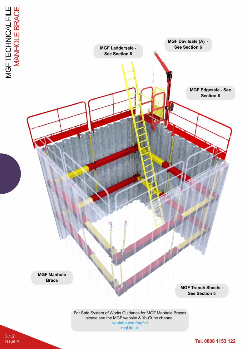
MGF Davitsafe (A) - See Section 6
MGF Manhole Brace
MGF Laddersafe - See Section 6
MGF Edgesafe - See Section 6
MGF Trench Sheets - See Section 5
For Safe System of Works Guidance for MGF Manhole Braces please see the MGF website & YouTube channel.
youtube.com/mgfltdmgf.ltd.uk
MAN
HO
LE B
RAC
EM
GF
TEC
HN
ICAL
FIL
E
3.1.3Issue 4
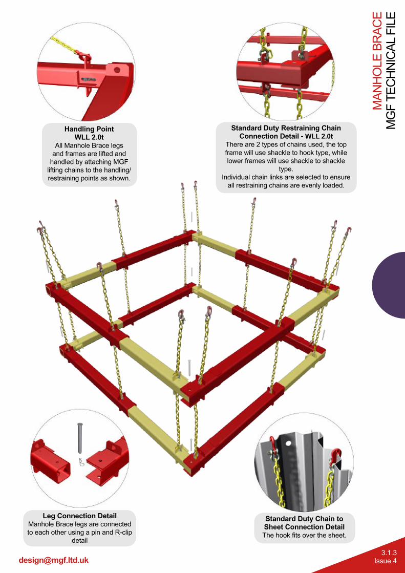
Standard Duty Chain to Sheet Connection DetailThe hook fits over the sheet.
Leg Connection DetailManhole Brace legs are connected to each other using a pin and R-clip
detail
Handling PointWLL 2.0t
All Manhole Brace legs and frames are lifted and
handled by attaching MGF lifting chains to the handling/restraining points as shown.
Standard Duty Restraining Chain Connection Detail - WLL 2.0t
There are 2 types of chains used, the top frame will use shackle to hook type, while lower frames will use shackle to shackle
type.Individual chain links are selected to ensure
all restraining chains are evenly loaded.
Tel. 0808 1153 122
MG
F TE
CH
NIC
AL F
ILE
MAN
HO
LE B
RAC
E
3.1.4Issue 4
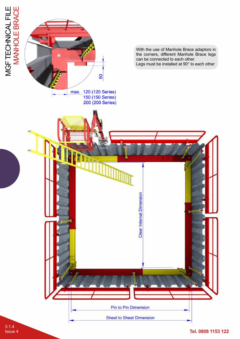
With the use of Manhole Brace adaptors in the corners, different Manhole Brace legs can be connected to each other.Legs must be installed at 90° to each other
MAN
HO
LE B
RAC
EM
GF
TEC
HN
ICAL
FIL
E
3.1.5Issue 4
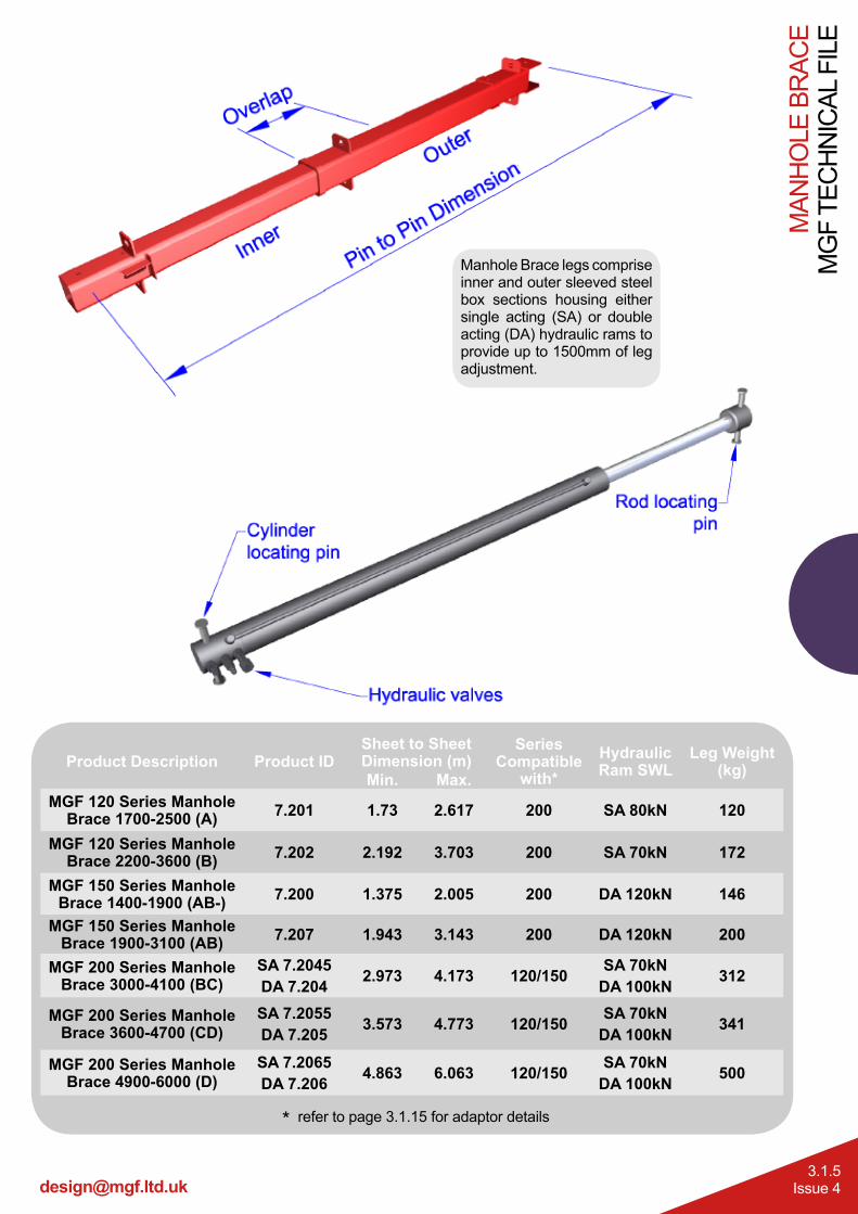
Manhole Brace legs comprise inner and outer sleeved steel box sections housing either single acting (SA) or double acting (DA) hydraulic rams to provide up to 1500mm of leg adjustment.
Product Description Product IDSheet to Sheet Dimension (m)
Series Compatible
with*Hydraulic Ram SWL
Leg Weight (kg)Min. Max.
MGF 120 Series Manhole Brace 1700-2500 (A) 7.201 1.73 2.617 200 SA 80kN 120
MGF 120 Series Manhole Brace 2200-3600 (B) 7.202 2.192 3.703 200 SA 70kN 172
MGF 150 Series Manhole Brace 1400-1900 (AB-) 7.200 1.375 2.005 200 DA 120kN 146
MGF 150 Series Manhole Brace 1900-3100 (AB) 7.207 1.943 3.143 200 DA 120kN 200
MGF 200 Series Manhole Brace 3000-4100 (BC)
SA 7.2045DA 7.204 2.973 4.173 120/150 SA 70kN
DA 100kN 312
MGF 200 Series Manhole Brace 3600-4700 (CD)
SA 7.2055DA 7.205 3.573 4.773 120/150 SA 70kN
DA 100kN 341
MGF 200 Series Manhole Brace 4900-6000 (D)
SA 7.2065DA 7.206 4.863 6.063 120/150 SA 70kN
DA 100kN 500
* refer to page 3.1.15 for adaptor details
Tel. 0808 1153 122
MG
F TE
CH
NIC
AL F
ILE
MAN
HO
LE B
RAC
E
3.1.6Issue 4
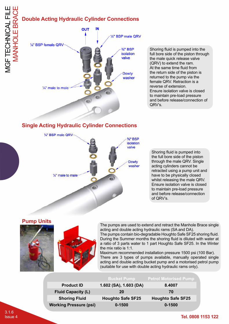
Double Acting Hydraulic Cylinder Connections
Single Acting Hydraulic Cylinder Connections
Shoring fluid is pumped into the full bore side of the piston through the male quick release valve (QRV) to extend the ram.At the same time fluid from the return side of the piston is returned to the pump via the female QRV. Retraction is a reverse of extension.Ensure isolation valve is closed to maintain pre-load pressure and before release/connection of QRV’s.
Shoring fluid is pumped into the full bore side of the piston through the male QRV. Single acting cylinders cannot be retracted using a pump unit and have to be physically closed whilst releasing the male QRV.Ensure isolation valve is closed to maintain pre-load pressure and before release/connection of QRV’s.
Pump UnitsThe pumps are used to extend and retract the Manhole Brace single acting and double acting hydraulic rams (SA and DA). The pumps contain bio-degradable Houghto Safe SF25 shoring fluid. During the Summer months the shoring fluid is diluted with water at a ratio of 3 parts water to 1 part Houghto Safe SF25. In the Winter the mix ratio is 1:1.Maximum recommended installation pressure 1500 psi (100 Bar).There are 3 types of pumps available, manually operated single acting and double acting bucket pump and a motorised petrol pump (suitable for use with double acting hydraulic rams only).
Bucket Pump Petrol Motorised PumpProduct ID 1.602 (SA), 1.603 (DA) 8.4007
Fluid Capacity (L) 20 70Shoring Fluid Houghto Safe SF25 Houghto Safe SF25
Working Pressure (psi) 0-1500 0-1500
MAN
HO
LE B
RAC
EM
GF
TEC
HN
ICAL
FIL
E
3.1.7Issue 4
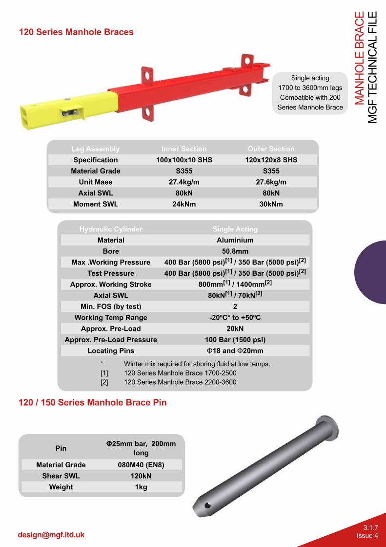
120 Series Manhole Braces
Single acting1700 to 3600mm legsCompatible with 200
Series Manhole Brace
Leg Assembly Inner Section Outer SectionSpecification 100x100x10 SHS 120x120x8 SHS
Material Grade S355 S355Unit Mass 27.4kg/m 27.6kg/mAxial SWL 80kN 80kN
Moment SWL 24kNm 30kNm
Hydraulic Cylinder Single ActingMaterial Aluminium
Bore 50.8mmMax .Working Pressure 400 Bar (5800 psi)[1] / 350 Bar (5000 psi)[2]
Test Pressure 400 Bar (5800 psi)[1] / 350 Bar (5000 psi)[2]
Approx. Working Stroke 800mm[1] / 1400mm[2]
Axial SWL 80kN[1] / 70kN[2]
Min. FOS (by test) 2Working Temp Range -20ºC* to +50ºC
Approx. Pre-Load 20kNApprox. Pre-Load Pressure 100 Bar (1500 psi)
Locating Pins Φ18 and Φ20mm
* Winter mix required for shoring fluid at low temps.[1] 120 Series Manhole Brace 1700-2500[2] 120 Series Manhole Brace 2200-3600
120 / 150 Series Manhole Brace Pin
Pin Φ25mm bar, 200mm long
Material Grade 080M40 (EN8)Shear SWL 120kN
Weight 1kg
Tel. 0808 1153 122
MG
F TE
CH
NIC
AL F
ILE
MAN
HO
LE B
RAC
E
3.1.8Issue 4
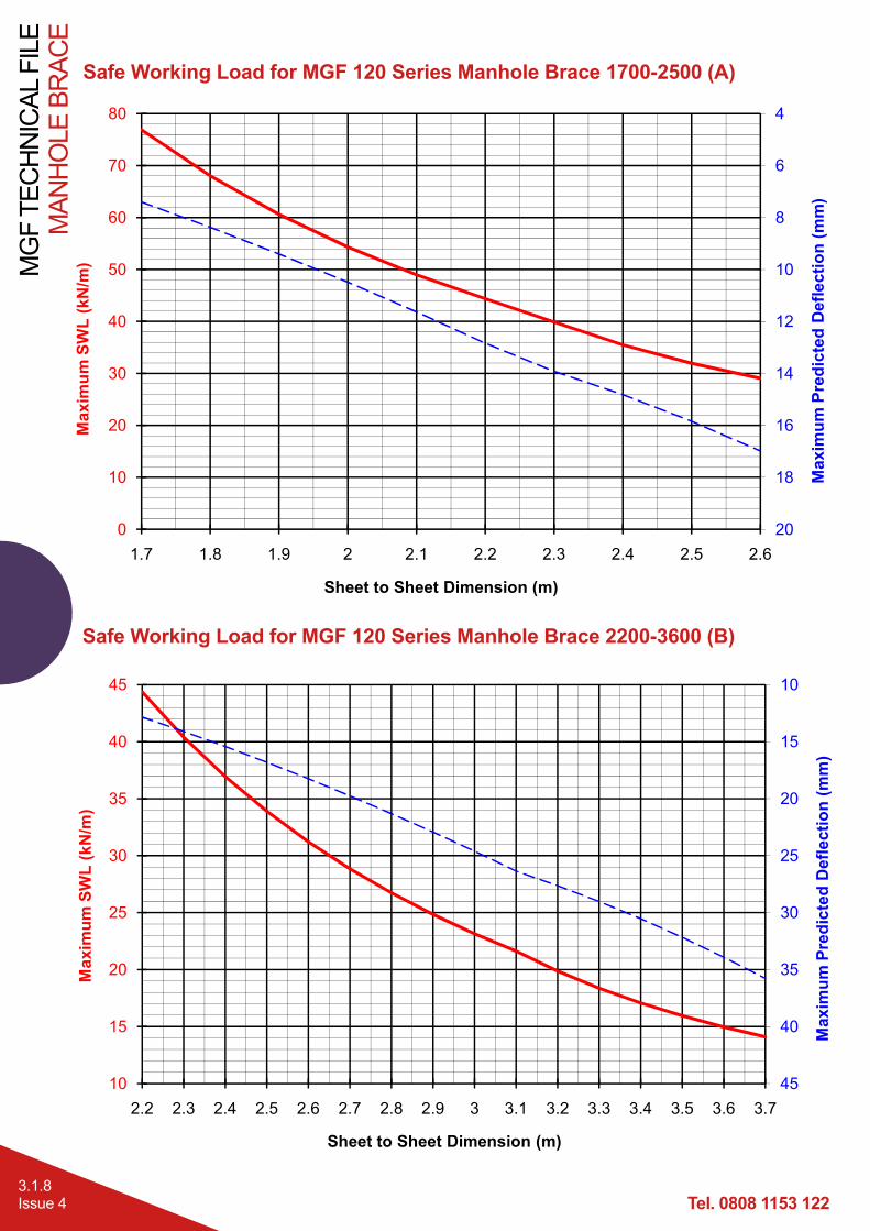
Safe Working Load for MGF 120 Series Manhole Brace 1700-2500 (A)
Safe Working Load for MGF 120 Series Manhole Brace 2200-3600 (B)
120 series (A Leg)
4
6
8
10
12
1430
40
50
60
70
80
Pred
icte
d D
efle
ctio
n (m
m)
xim
um S
WL
(kN
/m)
Page 1
4
6
8
10
12
14
16
18
200
10
20
30
40
50
60
70
80
1.7 1.8 1.9 2 2.1 2.2 2.3 2.4 2.5 2.6
Max
imum
Pre
dict
ed D
efle
ctio
n (m
m)
Max
imum
SW
L (k
N/m
)
Sheet to Sheet Dimension (m)120 series (B Leg)
10
15
20
25
30
3520
25
30
35
40
45
m P
redi
cted
Def
lect
ion
(mm
)
axim
um S
WL
(kN
/m)
Page 1
10
15
20
25
30
35
40
4510
15
20
25
30
35
40
45
2.2 2.3 2.4 2.5 2.6 2.7 2.8 2.9 3 3.1 3.2 3.3 3.4 3.5 3.6 3.7
Max
imum
Pre
dict
ed D
efle
ctio
n (m
m)
Max
imum
SW
L (k
N/m
)
Sheet to Sheet Dimension (m)
MAN
HO
LE B
RAC
EM
GF
TEC
HN
ICAL
FIL
E
3.1.9Issue 4
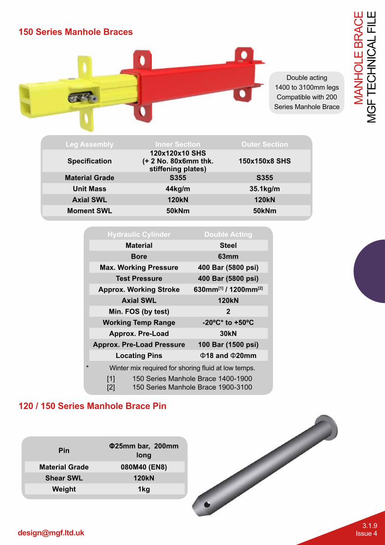
150 Series Manhole Braces
Leg Assembly Inner Section Outer Section
Specification120x120x10 SHS
(+ 2 No. 80x6mm thk. stiffening plates)
150x150x8 SHS
Material Grade S355 S355Unit Mass 44kg/m 35.1kg/mAxial SWL 120kN 120kN
Moment SWL 50kNm 50kNm
[1] 150 Series Manhole Brace 1400-1900 [2] 150 Series Manhole Brace 1900-3100
Hydraulic Cylinder Double ActingMaterial Steel
Bore 63mmMax. Working Pressure 400 Bar (5800 psi)
Test Pressure 400 Bar (5800 psi)Approx. Working Stroke 630mm[1] / 1200mm[2]
Axial SWL 120kNMin. FOS (by test) 2
Working Temp Range -20ºC* to +50ºCApprox. Pre-Load 30kN
Approx. Pre-Load Pressure 100 Bar (1500 psi)Locating Pins Φ18 and Φ20mm
* Winter mix required for shoring fluid at low temps.
Double acting1400 to 3100mm legsCompatible with 200
Series Manhole Brace
120 / 150 Series Manhole Brace Pin
Pin Φ25mm bar, 200mm long
Material Grade 080M40 (EN8)Shear SWL 120kN
Weight 1kg
Tel. 0808 1153 122
MG
F TE
CH
NIC
AL F
ILE
MAN
HO
LE B
RAC
E
3.1.10Issue 4
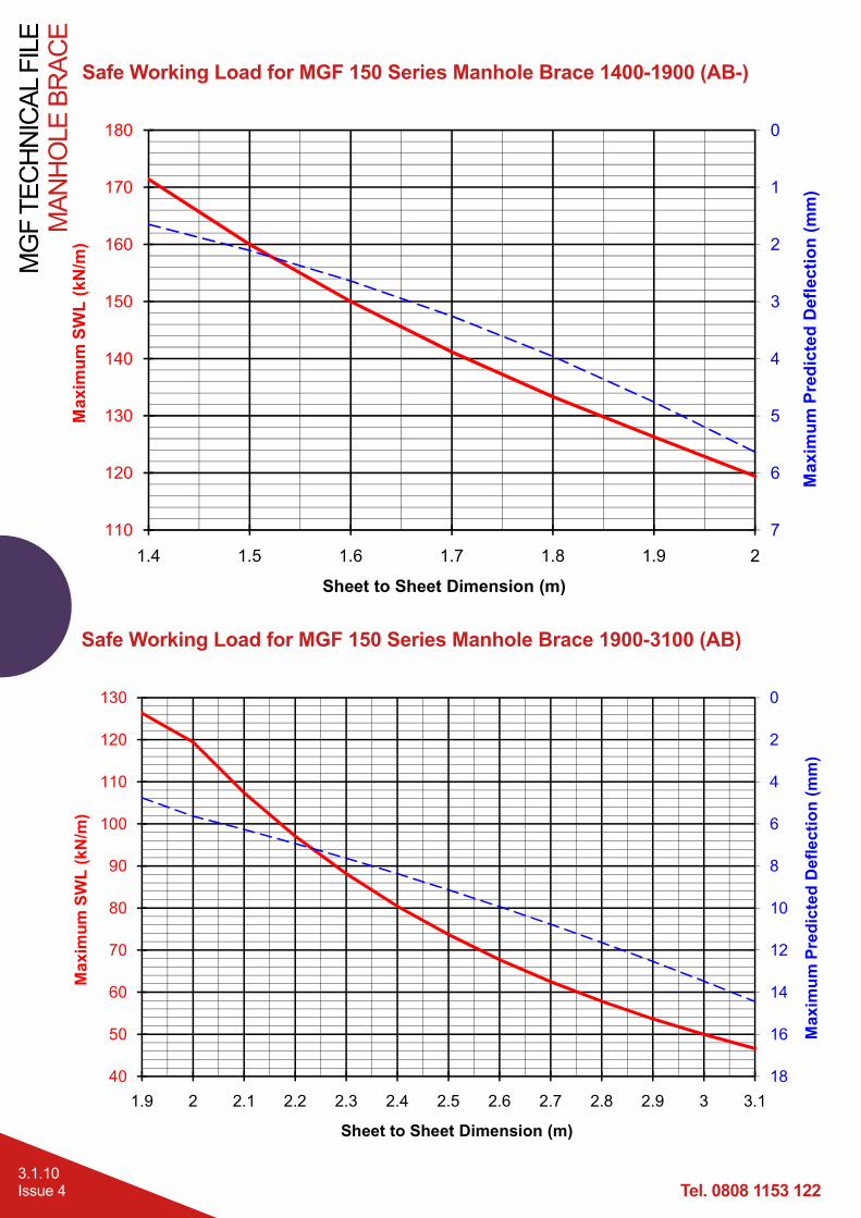
Safe Working Load for MGF 150 Series Manhole Brace 1400-1900 (AB-)
Safe Working Load for MGF 150 Series Manhole Brace 1900-3100 (AB)120 series (B Leg)
0
2
4
6
8
10
1270
80
90
100
110
120
130
Pre
dict
ed D
efle
ctio
n (m
m)
axim
um S
WL
(kN
/m)
Page 1
0
2
4
6
8
10
12
14
16
1840
50
60
70
80
90
100
110
120
130
1.9 2 2.1 2.2 2.3 2.4 2.5 2.6 2.7 2.8 2.9 3 3.1
Max
imum
Pre
dict
ed D
efle
ctio
n (m
m)
Max
imum
SW
L (k
N/m
)
Sheet to Sheet Dimension (m)
120 series (B Leg)
0
1
2
3
4
5130
140
150
160
170
180
m P
redi
cted
Def
lect
ion
(mm
)
Max
imum
SW
L (k
N/m
)
Page 1
0
1
2
3
4
5
6
7110
120
130
140
150
160
170
180
1.4 1.5 1.6 1.7 1.8 1.9 2
Max
imum
Pre
dict
ed D
efle
ctio
n (m
m)
Max
imum
SW
L (k
N/m
)
Sheet to Sheet Dimension (m)
MAN
HO
LE B
RAC
EM
GF
TEC
HN
ICAL
FIL
E
3.1.11Issue 4
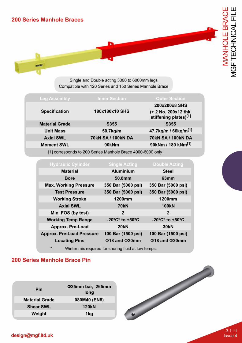
200 Series Manhole Braces
200 Series Manhole Brace Pin
Pin Φ25mm bar, 265mm long
Material Grade 080M40 (EN8)Shear SWL 120kN
Weight 1kg
* Winter mix required for shoring fluid at low temps.
Hydraulic Cylinder Single Acting Double ActingMaterial Aluminium Steel
Bore 50.8mm 63mmMax. Working Pressure 350 Bar (5000 psi) 350 Bar (5000 psi)
Test Pressure 350 Bar (5000 psi) 350 Bar (5000 psi)Working Stroke 1200mm 1200mm
Axial SWL 70kN 100kNMin. FOS (by test) 2 2
Working Temp Range -20ºC* to +50ºC -20ºC* to +50ºCApprox. Pre-Load 20kN 30kN
Approx. Pre-Load Pressure 100 Bar (1500 psi) 100 Bar (1500 psi)Locating Pins Φ18 and Φ20mm Φ18 and Φ20mm
Single and Double acting 3000 to 6000mm legsCompatible with 120 Series and 150 Series Manhole Brace
Leg Assembly Inner Section Outer Section
Specification 180x180x10 SHS200x200x8 SHS
(+ 2 No. 200x12 thk. stiffening plates)[1]
Material Grade S355 S355Unit Mass 50.7kg/m 47.7kg/m / 66kg/m[1]
Axial SWL 70kN SA / 100kN DA 70kN SA / 100kN DAMoment SWL 90kNm 90kNm / 180 kNm[1]
[1] corresponds to 200 Series Manhole Brace 4900-6000 only

Tel. 0808 1153 122
MG
F TE
CH
NIC
AL F
ILE
MAN
HO
LE B
RAC
E
3.1.12Issue 4
Safe Working Load for MGF 200 Series Manhole Brace 3000-4100 DA (BC)
Safe Working Load for MGF 200 Series Manhole Brace 3000-4100 SA (BC)
120 series (B Leg) SA
0
5
10
1555
60
65
70
m P
redi
cted
Def
lect
ion
(mm
)
xim
um S
WL
(kN
/m)
Page 1
0
5
10
15
20
2545
50
55
60
65
70
3 3.1 3.2 3.3 3.4 3.5 3.6 3.7 3.8 3.9 4 4.1
Max
imum
Pre
dict
ed D
efle
ctio
n (m
m)
Max
imum
SW
L (k
N/m
)
Sheet to Sheet Dimension (m)120 series (B Leg) SA
0
5
1040
45
50
Pre
dict
ed D
efle
ctio
n (m
m)
Max
imum
SW
L (k
N/m
)
Page 1
0
5
10
15
2030
35
40
45
50
3 3.1 3.2 3.3 3.4 3.5 3.6 3.7 3.8 3.9 4 4.1
Max
imum
Pre
dict
ed D
efle
ctio
n (m
m)
Max
imum
SW
L (k
N/m
)
Sheet to Sheet Dimension (m)
MAN
HO
LE B
RAC
EM
GF
TEC
HN
ICAL
FIL
E
3.1.13Issue 4
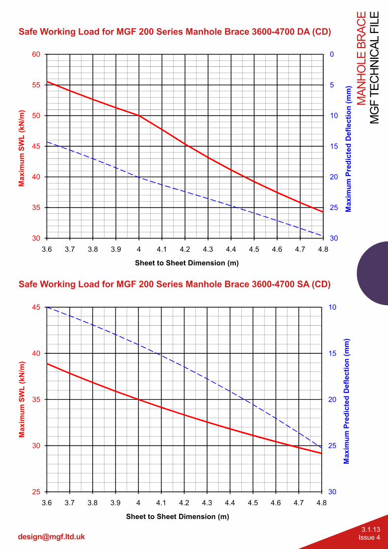
Safe Working Load for MGF 200 Series Manhole Brace 3600-4700 DA (CD)
Safe Working Load for MGF 200 Series Manhole Brace 3600-4700 SA (CD)
120 series (B Leg) SA
0
5
10
15
2040
45
50
55
60
m P
redi
cted
Def
lect
ion
(mm
)
Max
imum
SW
L (k
N/m
)
Page 1
0
5
10
15
20
25
3030
35
40
45
50
55
60
3.6 3.7 3.8 3.9 4 4.1 4.2 4.3 4.4 4.5 4.6 4.7 4.8
Max
imum
Pre
dict
ed D
efle
ctio
n (m
m)
Max
imum
SW
L (k
N/m
)
Sheet to Sheet Dimension (m)120 series (B Leg) SA
10
15
2035
40
45
m P
redi
cted
Def
lect
ion
(mm
)
Max
imum
SW
L (k
N/m
)
Page 1
10
15
20
25
3025
30
35
40
45
3.6 3.7 3.8 3.9 4 4.1 4.2 4.3 4.4 4.5 4.6 4.7 4.8
Max
imum
Pre
dict
ed D
efle
ctio
n (m
m)
Max
imum
SW
L (k
N/m
)
Sheet to Sheet Dimension (m)
Tel. 0808 1153 122
MG
F TE
CH
NIC
AL F
ILE
MAN
HO
LE B
RAC
E
3.1.14Issue 4
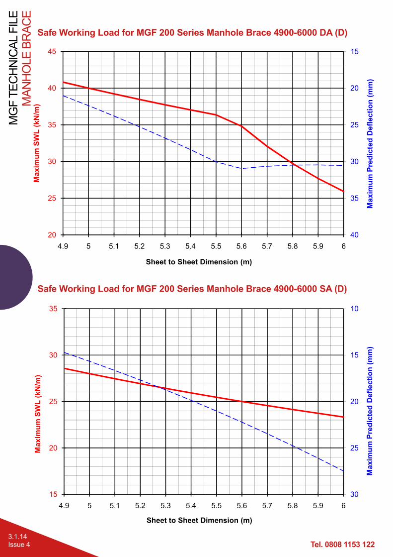
Safe Working Load for MGF 200 Series Manhole Brace 4900-6000 DA (D)
Safe Working Load for MGF 200 Series Manhole Brace 4900-6000 SA (D)
120 series (A Leg)
15
20
25
3030
35
40
45
m P
redi
cted
Def
lect
ion
(mm
)
Max
imum
SW
L (k
N/m
)
Page 1
15
20
25
30
35
4020
25
30
35
40
45
4.9 5 5.1 5.2 5.3 5.4 5.5 5.6 5.7 5.8 5.9 6
Max
imum
Pre
dict
ed D
efle
ctio
n (m
m)
Max
imum
SW
L (k
N/m
)
Sheet to Sheet Dimension (m)120 series (A Leg)
10
15
2025
30
35
Pred
icte
d D
efle
ctio
n (m
m)
xim
um S
WL
(kN
/m)
Page 1
10
15
20
25
3015
20
25
30
35
4.9 5 5.1 5.2 5.3 5.4 5.5 5.6 5.7 5.8 5.9 6
Max
imum
Pre
dict
ed D
efle
ctio
n (m
m)
Max
imum
SW
L (k
N/m
)
Sheet to Sheet Dimension (m)
MAN
HO
LE B
RAC
EM
GF
TEC
HN
ICAL
FIL
E
3.1.15Issue 4
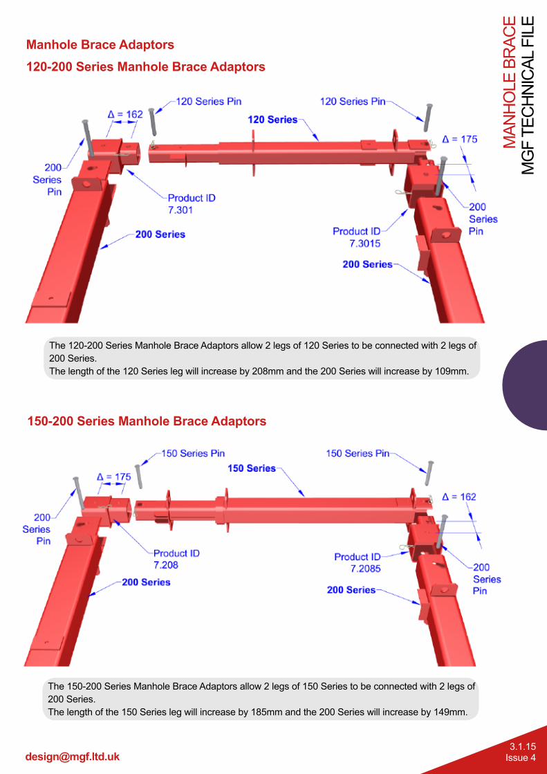
Manhole Brace Adaptors120-200 Series Manhole Brace Adaptors
150-200 Series Manhole Brace Adaptors
The 150-200 Series Manhole Brace Adaptors allow 2 legs of 150 Series to be connected with 2 legs of 200 Series. The length of the 150 Series leg will increase by 185mm and the 200 Series will increase by 149mm.
The 120-200 Series Manhole Brace Adaptors allow 2 legs of 120 Series to be connected with 2 legs of 200 Series. The length of the 120 Series leg will increase by 208mm and the 200 Series will increase by 109mm.
Tel. 0808 1153 122
MG
F TE
CH
NIC
AL F
ILE
MAN
HO
LE B
RAC
E
3.1.16Issue 4
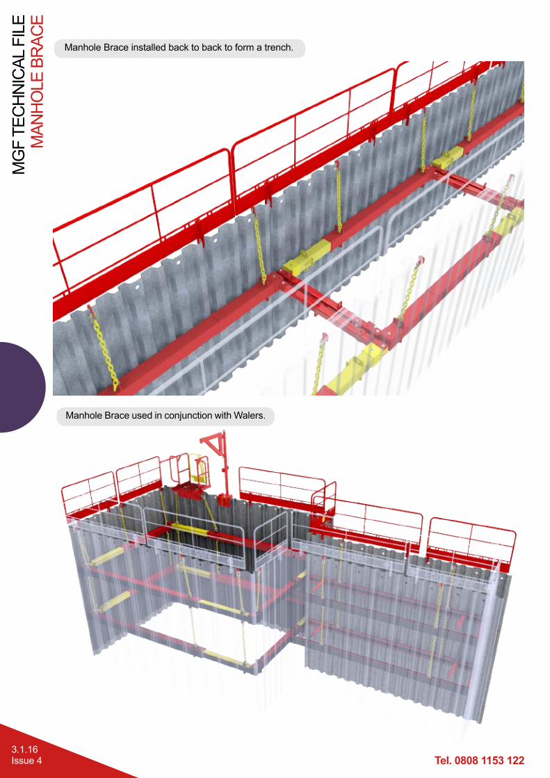
Manhole Brace installed back to back to form a trench.
Manhole Brace used in conjunction with Walers.