Managing VoIP Quality Issues in converged Networks -...
79
© 2006 Cisco Systems, Inc. All rights reserved. Cisco Confidential 1 Managing VoIP Quality Issues in converged Networks Faisal Chaudhry [email protected] Solutions Architect Cisco Systems Syed Khurram [email protected] Manager, Advance Services Cisco Systems
Transcript of Managing VoIP Quality Issues in converged Networks -...

© 2006 Cisco Systems, Inc. All rights reserved. Cisco Confidential 1
Managing VoIP Quality Issues in converged Networks
Faisal Chaudhry [email protected]
Solutions Architect Cisco Systems
Syed Khurram [email protected]
Manager, Advance Services Cisco Systems

© 2008 Cisco Systems, Inc. All rights reserved. 2
Agenda
Architectures using VoIP Recognizing Voice Quality Issues Classifying Voice Quality Attributes to Root
Cause Address Voice Quality by Implementing
Quality of Service (QoS) Echo Q & A

© 2008 Cisco Systems, Inc. All rights reserved. 3
PBX PBX
Router/GW Router/GW
Call Processing Call Processing
Toll Bypass
Router/GW Router/GW
IP WAN
IP WAN
End-to-End IP Telephony with Application Enablement
IP Telephony
Enterprise ‘VoIP’ Solution Sets: Toll Bypass and IP Telephony
IP Phones IP Phones
Analog or Digital Phones
Analog or Digital Phones
© 2008 Cisco Systems, Inc. All rights reserved. 4
Branch A IP WAN
Branch B
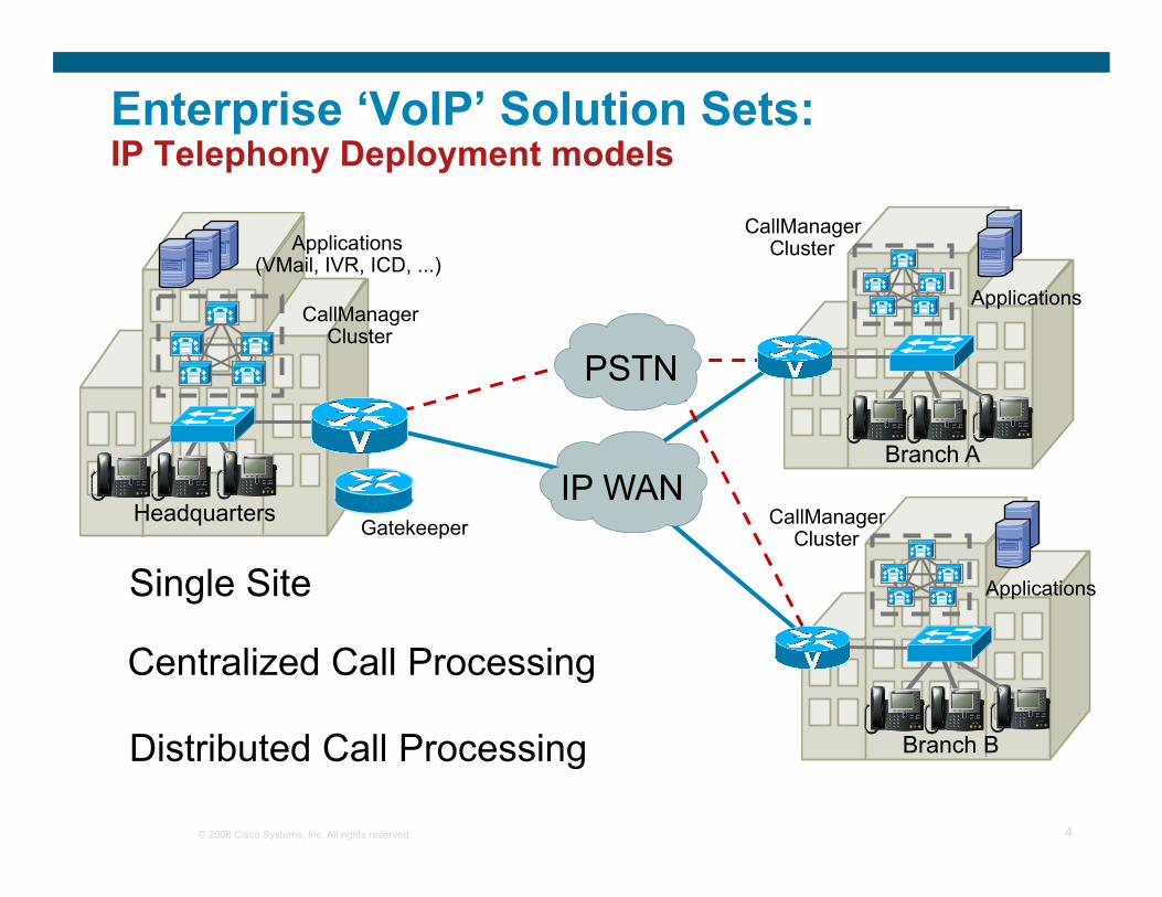
Centralized Call Processing
PSTN
Headquarters
Applications (VMail, IVR, ICD, ...)
CallManager Cluster
Gatekeeper GK
Applications
CallManager Cluster
Applications
CallManager Cluster
Distributed Call Processing
Single Site
Enterprise ‘VoIP’ Solution Sets: IP Telephony Deployment models

© 2008 Cisco Systems, Inc. All rights reserved. 5
Transit/Tandem
Business & Residential
Access
Residential Access PBX
PSTN Gateway
SIP Proxy (IMS)
IP Phone
MG
Call Manager
Voice CPE
GK
H.323 Gatekeeper
Data Network
VoCable /VoETTx
Local Services Call Agent PSTN
PSTN
Service Provider Voice Architectures

© 2008 Cisco Systems, Inc. All rights reserved. 6
SSP SLT SGW Softswitch SSP SLT SGW
Gateway
SSP SLT SGW
Gateway
Gateway
SSP SLT SGW
Gateway
Signalling : MGCP, H.323, SIP, SS7 (SIGTRAN)
VoIP Bearer traffic
Remote sites over WAN
Service Provider VoIP Transit and Class 5 Replacement

© 2008 Cisco Systems, Inc. All rights reserved. 7
PSTN Interconnect
MxU Res. Villas
Softswitch
IP Network Triple play services
IP-IP Interconnect
SBC Session Border Controller
Service Provider Triple Play

© 2008 Cisco Systems, Inc. All rights reserved. 8
Managed Voice service for Enterprises by SP: On-premises or Centralized Hosted Call Control Interface to the PSTN/PLMN (Centralized or on-premises) Interface to Legacy equipment (such as PBX, Voicemail) Dial plan Management Billing Customer Premises Equipment e.g. Analog or IP Phones Need to cater for QoS, Resiliency, Security …
Service Provider Hosted and Managed IP Telephony

© 2008 Cisco Systems, Inc. All rights reserved. 9
Customer Premises Sites
SP Hosted Infrastructure (VoIP Transit)
SS7 Signaling
TDM Voice
Voice Gateways
H.323 Gatekeepers
(or SIP) GK
LAN Switch
MGCP
GK
SP Hosted IP Telephony
Access (DSL, ETTx…)
Firewall
Media Resources (Conferencing,
Announcements etc)
Call Control
Central Voicemail
Central LDAP
Softswitch
Service Provider Hosted and Managed IP Telephony

© 2008 Cisco Systems, Inc. All rights reserved. 10
Softswitch SS7
Signaling
TDM Voice
Voice Gateway
H.323 Gatekeepers
(or SIP Proxy) GK
LAN Switch
Firewall Access Router
Voicemail
MGCP
GK
(optional) PSTN
(optional) PSTN
Call Control
Voicemail
Call Control
Service Provider Managed IP Telephony
Customer Premises Sites
SP Hosted Infrastructure (VoIP Transit)
Access (DSL, ETTx…)

© 2008 Cisco Systems, Inc. All rights reserved. 11
Agenda
Architectures using VoIP Recognizing Voice Quality Issues Classifying Voice Quality Attributes to Root
Cause Address Voice Quality by Implementing
Quality of Service (QoS) Echo Q & A

© 2008 Cisco Systems, Inc. All rights reserved. 12
Categorizing and Defining the Symptoms
Noise Conversation is still Intelligible; presence of static, hum, crosstalk intermittent popping
Voice distortion Problem that affects the voice itself Echoed voice Garbled voice Volume distortion

© 2008 Cisco Systems, Inc. All rights reserved. 13
Noise
Clicking Cause: Clock Slips or Other Digital Errors
Crackling Cause: Poor Electrical Connection, Electrical Interference
Crosstalk Cause: Signal Leakage Due to Wires Located in Close Proximity
Absolute Silence Cause: Aggressive Voice Activity Detection (VAD)

© 2008 Cisco Systems, Inc. All rights reserved. 14
Noise (Cont.)
Hissing Cause: VAD
Static Cause: Codec Mismatch; Enhanced by VAD
© 2008 Cisco Systems, Inc. All rights reserved. 15
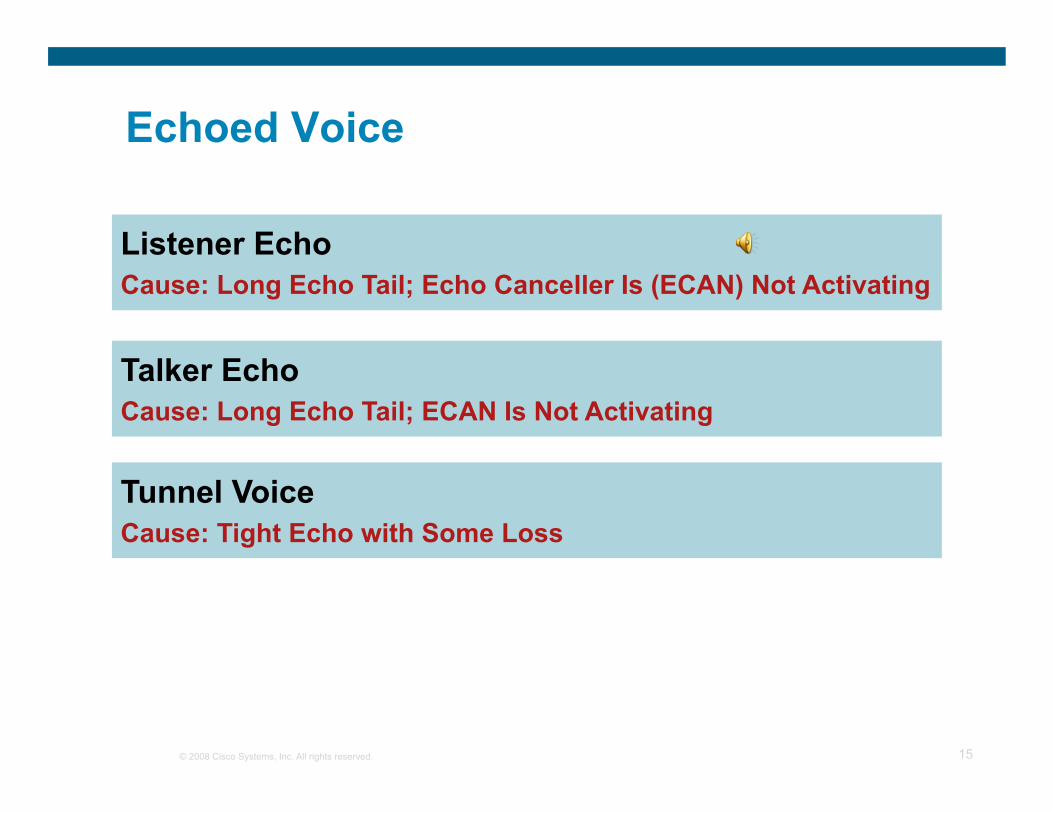
Echoed Voice
Listener Echo Cause: Long Echo Tail; Echo Canceller Is (ECAN) Not Activating
Talker Echo Cause: Long Echo Tail; ECAN Is Not Activating
Tunnel Voice Cause: Tight Echo with Some Loss

© 2008 Cisco Systems, Inc. All rights reserved. 16
Garbled Voice
Choppy Voice Cause: Consecutive Packets Lost or Excessively Delayed Disabling DSP Predictive Insertion Where Silence Is Inserted Instead
Synthetic Voice Cause: Single Packet Loss or Delay Beyond the Bounds of the De-Jitter Buffer Playout Period
Underwater Voice Cause: A Common Cause of This Problem Is G729 IETF and Pre-IETF Codec Mismatch

© 2008 Cisco Systems, Inc. All rights reserved. 17
Volume Distortion
Fuzzy Voice Cause: Too Much Gain on the Signal
Muffled Voice Cause: Overdriven Signal or Some Other Cause That Eliminates or Reduces Signal Level at Frequencies Inside the Key Range for Voice (Between 440 and 3500)
Soft Voice Cause: Attenuated Signal
Tinny Voice Cause: Overdriven Signal that Eliminates or Reduces Signal Level at Frequencies Outside the Key Range for Voice (Between 440Hz and 3500Hz)

© 2008 Cisco Systems, Inc. All rights reserved. 18
Agenda
Architectures using VoIP Recognizing Voice Quality Issues Classifying Voice Quality Attributes to Root
Cause Address Voice Quality by Implementing
Quality of Service (QoS) Echo Q &A

© 2008 Cisco Systems, Inc. All rights reserved. 19
Problem and Root Cause Association
Gain Adjustment
Packet Loss
Delay
Echo Return Loss
Jitter
VAD
Absolute Silence
Fuzzy Voice Synthetic Voice
Soft Voice Muffled Voice
Choppy Voice
Static and Hissing
Listener Echo

© 2008 Cisco Systems, Inc. All rights reserved. 20
• Absolute silence • Clipping • Static and hissing • Underwater voice
Classifying Voice Quality Attributes to Root Cause
Quality of Service
Network Transmission
Loss Plan
VAD, Codecs
• Loss • Jitter • Delay • Synthetic voice • Robotic voice • Choppy voice • Periods of silence
• Gain adjustment • ERL
• Talker echo • Listener echo • Tunnel voice • Fuzzy voice • Muffled voice • Tinny voice
Synchronization, Cabling
• Crackling • Clicking • Crosstalk

© 2008 Cisco Systems, Inc. All rights reserved. 21
Basic Guidelines for of Voice over IP Transmit voice traffic the fastest way possible
Delay is bad (worsens echo, awkward conversations, etc.) Minimize as many sources of delay as possible Goal: keep delay to less than 150ms
Transmit VOIP packets as a steady, smooth stream Any delay should be consistent Inconsistent delay is called “Jitter” Compensating for Jitter creates additional delay
Drop any packets received out of order Voice does not tolerate delays…it’s better to drop the packet CODEC logic can compensate for some dropped packets
Above all…it’s gotta sound good (subjective)

© 2008 Cisco Systems, Inc. All rights reserved. 22
Agenda
Architectures using VoIP Recognizing Voice Quality Issues Classifying Voice Quality Attributes to Root
Cause Address Voice Quality by Implementing
Quality of Service (QoS) Echo Q & A

© 2008 Cisco Systems, Inc. All rights reserved. 23
Voice QoS Requirements End-to-End Latency
Delay Target
Avoid the “Human Ethernet”
Time (msec) 0 100 200 300 400 500 600 700 800
Hello? Hello?

© 2008 Cisco Systems, Inc. All rights reserved. 24
Elements That Affect End-to-End Delay
IP WAN
Campus Branch Office
PSTN
Fixed (Sampling rate)
CODEC
Variable (Can Be Reduced
Using LLQ)
Queuing
Variable (Can Be Reduced
Using LFI)
Serialization Propagation and Network
20–50 ms
Jitter Buffer
End-to-End Delay (Should Be < 150 ms) As per ITU G.114 Recommendations

© 2008 Cisco Systems, Inc. All rights reserved. 25
Voice
3
Voice
3
Voice
3
Voice
3 Reconstructed Voice Sample
Packet Loss
Voice QoS Requirements Factors which Degrade Voice Quality

© 2008 Cisco Systems, Inc. All rights reserved. 26
Current DSP CODEC algorithms can correct for 30 msec of lost voice by using predictor algorithm
Generally 1 G.729A voice packet contains 20 msec of voice
Lost packets induce “clipping” and temporarily expand the jitter buffer, which increases end-to-end latency
One lost Voice over IP packet causes a MODEM retrain; Two drops can cause a call disconnect
Causes of packet loss: Network quality, network congestion and delay variation
Voice
3
Voice
3 Voice
3
Voice
3 Reconstructed Voice Sample
Packet Loss
Voice QoS Requirements Factors which Degrade Voice Quality

© 2008 Cisco Systems, Inc. All rights reserved. 27
t Sender Transmits A C
D1 D2 = D1
Sender Receiver
PBX PBX Network
C
B
t Sink Receives
Variable Delay – Jitter
B A
Voice QoS Requirements Factors which Degrade Voice Quality

© 2008 Cisco Systems, Inc. All rights reserved. 28
When voice call starts, the de-jitter buffer fills up to the quiescent point
As voice frames arrive too fast, the queue fills As voice frames arrive too slowly, the queue empties
Depth of queue varies with network operation Over-/-under flow will cause gaps in speech and underwater voice
V V V V V V V V V V V V
Under Flow: Queue Empties If
Voice Frame Arrive too Slow
Fixed Playout Rate
= Codec Frame Rate
Voice Frames to DSP decode
Voice Frames From Network
Variable Arrival Rate
= Codec Frame Rate +/- Δ
Quiescent Point: Specified in mSec
V V V V V
Over Flow: Queue Fills If Voice Frame
Arrive Too Fast
Voice QoS Requirements De-Jitter Buffer Operation
Normal Operating Queue Depth

© 2008 Cisco Systems, Inc. All rights reserved. 29
Voice QoS Requirements Summary for Voice
Latency ≤ 150 ms Jitter ≤ 30 ms Loss ≤ 1% 17–106 kbps guaranteed priority
bandwidth per call Bandwidth for Voice-Control traffic
per call SCCP: 150 bps + Layer 2 overhead
CAC must be enabled (Integrated Services)
Smooth Benign Drop sensitive Delay sensitive UDP priority
Voice One-Way Requirements
© 2008 Cisco Systems, Inc. All rights reserved. 30
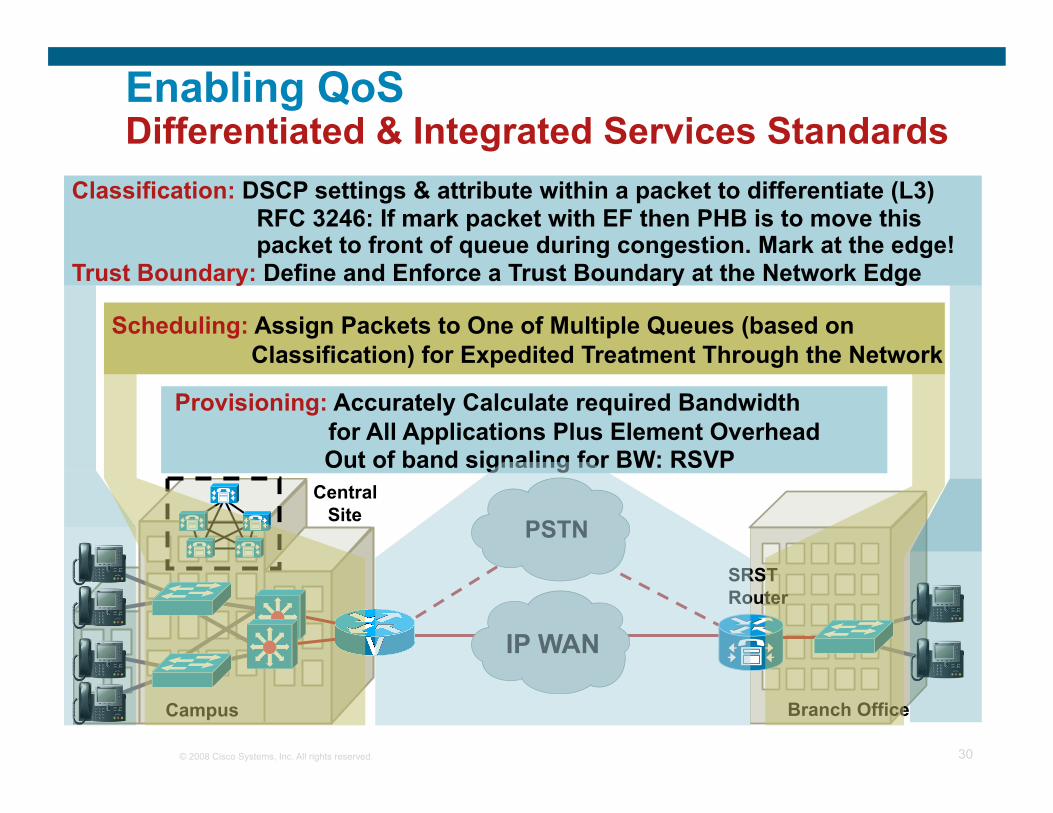
Enabling QoS Differentiated & Integrated Services Standards
Campus Branch Office
Central Site
SRST Router
IP WAN
PSTN
Classification: DSCP settings & attribute within a packet to differentiate (L3) RFC 3246: If mark packet with EF then PHB is to move this packet to front of queue during congestion. Mark at the edge! Trust Boundary: Define and Enforce a Trust Boundary at the Network Edge

© 2008 Cisco Systems, Inc. All rights reserved. 31
Quality of Service Operations How Does It Work and Essential Elements
Classification and Marking
Queuing and Dropping
Post-Queuing Operations
Classification & Marking: The first element to a QoS policy is to classify/identify the traffic that is to be treated differently. Following
classification, marking tools can set an attribute of a frame or packet to a specific value. Policing:
Determine whether packets are conforming to administratively-defined traffic rates and take action accordingly. Such action could include marking, remarking or dropping a packet.
Scheduling (including Queuing & Dropping): Scheduling tools determine how a frame/packet exits a device. Queuing algorithms are activated only when
a device is experiencing congestion and are deactivated when the congestion clears.
Link Specific Mechanisms (Shaping, Fragmentation, Compression, Tx Ring) Offers network administrators tools to optimize link utilization

© 2008 Cisco Systems, Inc. All rights reserved. 32
Classification Tools Ethernet 802.1Q Class of Service
802.1p user priority field also called Class of Service (CoS)
Different types of traffic are assigned different CoS values
CoS 6 and 7 are reserved for network use
TAG 4 Bytes
Three Bits Used for CoS (802.1p User Priority)
Data FCS PT SA DA SFD Pream. Type
802.1Q/p Header
PRI VLAN ID CFI
Ethernet Frame
1
2
3
4
5
6
7
0 Best Effort Data
Bulk Data
Critical Data
Call Signaling
Video
Voice
Routing
Reserved CoS Application

© 2008 Cisco Systems, Inc. All rights reserved. 33
Classification Tools IP Precedence and DiffServ Code Points
IPv4: Three most significant bits of ToS byte are called IP Precedence (IPP)—other bits unused
DiffServ: Six most significant bits of ToS byte are called DiffServ Code Point (DSCP)—remaining two bits used for flow control
DSCP is backward-compatible with IP precedence
7 6 5 4 3 2 1 0
ID Offset TTL Proto FCS IP SA IP DA Data Len Version Length
ToS Byte
DiffServ Code Point (DSCP) IP ECN
IPv4 Packet
IP Precedence Unused Standard IPv4
DiffServ Extensions

© 2008 Cisco Systems, Inc. All rights reserved. 34
Classification Tools DSCP Per-Hop Behaviors
IETF RFCs have defined special keywords, called Per-Hop Behaviors, for specific DSCP markings
EF: Expedited Forwarding (RFC3246) (DSCP 46)
CSx: Class Selector (RFC2474) Where x corresponds to the IP Precedence value (1–7) (DSCP 8, 16, 24, 32, 40, 48, 56)
AFxy: Assured Forwarding (RFC2597) Where x corresponds to the IP Precedence value
(only 1–4 are used for AF Classes) And y corresponds to the Drop Preference value (either 1 or 2 or 3) With the higher values denoting higher likelihood of dropping (DSCP 10/12/14, 18/20/22, 26/28/30, 34/36/38)
BE: Best Effort or Default Marking Value (RFC2474) (DSCP 0)

© 2008 Cisco Systems, Inc. All rights reserved. 35
IP Precedence and DSCP diffs
ToS Byte P2 P1 P0 T2 T1 T0 CU1 CU0
• IP precedence—three bits (P2 to P0) • Delay, Throughput and Reliability—three bits (T2 to T0) • CU (Currently Unused)—two bits(CU1-CU0)
DiffServ Field DS5 DS4 DS3 DS2 DS1 DS0 ECN ECN
• DSCP—six bits (DS5-DS0) • ECN—two bits • The standardized DiffServ field of the packet is marked with a value so that the packet receives
particular forwarding treatment or PHB, at each network node.

© 2008 Cisco Systems, Inc. All rights reserved. 36
Example of IP precedence and DSCP IP Prec 5 (101) maps to IP DSCP 101 000 ToS Byte
1 0 1 T2 T1 T0 CU2 CU0 DiffServ Field
1 0 1 0 0 0 ECN ECN
Precedence Level Description 7 Stays the same (link layer and routing protocol keep
alive) 6 Stays the same (used for IP routing protocols) 5 Express Forwarding (EF) 4 Class 4 3 Class 3 2 Class 2 1 Class 1 0 Best effort

© 2008 Cisco Systems, Inc. All rights reserved. 37
Assured Forwarding DSCP chart
Drop Class 1 Class 2 Class 3 Class 4 Low 001010
AF11 DSCP 10
010010 AF21 DSCP 18
011010 AF31 DSCP 26
100010 AF41 DSCP 34
Medium 001100 AF12 DSCP 12
010100 AF 22 DSCP 20
011100 AF32 DSCP 28
100100 AF42 DSCP 36
High 001110 AF13 DSCP 14
010110 AF23 DSCP 22
011110 AF33 DSCP 30
100110 AF43 DSCP 38

© 2008 Cisco Systems, Inc. All rights reserved. 38
WAN
QoS is Needed to Minimize Packet Loss, Delay and Delay Variation
Where QoS Is Needed Central Site Remote Branch
• Layer 3 Policing • Multiple Queues on All Ports; Priority Queuing for VoIP • WRED Within Data Queue for Congestion Management
• Define trust boundary • Classification on IP Phone and Access Switch • Multiple Queues on IP Phone and Access Ports
• Classification and Trust Boundaries on IP Phone , Access Layer Switch and Router • Multiple Queues on IP Phone and All Access Ports
QoS—Campus Access QoS—Campus Distribution
• Low-latency Queuing • Link Fragmentation and Interleave • Bandwidth Provisioning • Admission Control
QoS—WAN QoS—Branch
© 2008 Cisco Systems, Inc. All rights reserved. 39
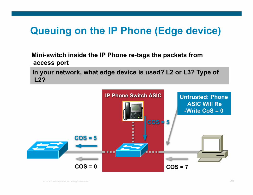
Queuing on the IP Phone (Edge device)
COS = 5
COS = 0
COS = 5
COS = 7
Untrusted: Phone ASIC Will Re
-Write CoS = 0
Mini-switch inside the IP Phone re-tags the packets from access port In your network, what edge device is used? L2 or L3? Type of L2?

© 2008 Cisco Systems, Inc. All rights reserved. 40
• Priority Queue (PQ) is for VoIP RTP traffic (CoS = 5)
• Round-Robin Scheduling with a PQ Timer
TX Voice RTP Packets
Queue 0 (PQ)
Queue 1 Queue 2 Queue 3
Queue ? RX
Queuing on the Edge device (IP Phone)
© 2008 Cisco Systems, Inc. All rights reserved. 41
QoS in Campus

© 2008 Cisco Systems, Inc. All rights reserved. 42
Is QoS Needed in the Campus?
“Just throw more bandwidth at it. That will solve the problem!”
Maybe, Maybe Not; Campus Congestion Is a Buffer Management Issue

© 2008 Cisco Systems, Inc. All rights reserved. 43
Campus QoS Considerations Typical Campus Oversubscription Ratios
Access
Distribution
Core

© 2008 Cisco Systems, Inc. All rights reserved. 44
Si Si
Area’s Where QoS Maybe a Concern
TX TX TX TX TX TX Access
Distribution
Core
Access, Distribution and Core Queuing
Output buffers can reach 100% in campus networks When an output buffer congests, dropped packets occur at the
ingress interfaces QoS required when there is a possibility of congestion in buffers Multiple queues are the best way to “guarantee” voice quality

© 2008 Cisco Systems, Inc. All rights reserved. 45
Tx Buffer Congestion
Ethernet Switch
Voice
To Core Data
Data
Data RX
RX
RX
RX
TX
Data Flows “Hog” Tx Buffer
Additional Flows, Including Voice,
Can Not Get Access to Tx
Buffer

© 2008 Cisco Systems, Inc. All rights reserved. 46
Guaranteed Voice Requires Multiple Queues
Ethernet Switch
Voice
To Core Data
Data
Data RX
RX
RX
RX
Queue Assignment Based on CoS/ToS
Classification
Voice Put Into “Delay and Drop” Sensitive Queue
TX

© 2008 Cisco Systems, Inc. All rights reserved. 47
Core
Distribution
Access LAN Switch
LAN Switches
MGCP Gateway
H.323 Gateway
Call Control (e.g. Softswitch)
4/2
Campus QoS—Access Layer
Call Signaling is control plane for VoIP traffic
All VoIP Control Plane Traffic should be Classified as DSCP=AF31 in the VoIP Gateway or from the LAN Switches e.g.
SIP: UDP 5060 Skinny Control: TCP 2000-2002 MGCP Control: UDP 2427 H.323 Control: TCP 1720 TCP
11000- 11999
Control and Management Plane Traffic
4/3 4/4

© 2008 Cisco Systems, Inc. All rights reserved. 48
QoS in WAN

© 2008 Cisco Systems, Inc. All rights reserved. 49
WAN Edge QoS Design Considerations QoS Requirements of WAN Aggregators
WAN Aggregator (WAG)
WAN Edges
Campus Distribution/Core
Switches
LAN Edges
WAN
Queuing/Dropping/ Shaping/Link-Efficiency Policies
for Campus-to-Branch Traffic
© 2008 Cisco Systems, Inc. All rights reserved. 50
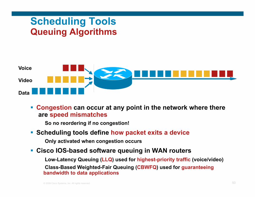
Scheduling Tools Queuing Algorithms
Congestion can occur at any point in the network where there are speed mismatches
So no reordering if no congestion!
Scheduling tools define how packet exits a device Only activated when congestion occurs
Cisco IOS-based software queuing in WAN routers Low-Latency Queuing (LLQ) used for highest-priority traffic (voice/video) Class-Based Weighted-Fair Queuing (CBWFQ) used for guaranteeing
bandwidth to data applications
Voice
Video
Data 3 3
2 2
1 1

© 2008 Cisco Systems, Inc. All rights reserved. 51
3 1 2 3 0 2 0 2 1 2 0 1
TAIL DROP
3
3
3
WRED
0 1
0
1
0
3
Queue
Scheduling Tools Congestion Avoidance Algorithms
Queueing algorithms manage the front of the queue i.e. which packets get transmitted first
Congestion avoidance algorithms, like Weighted-Random Early-Detect (WRED), manage the tail of the queue
i.e. which packets get dropped first when queuing buffers fill WRED can operate in a DiffServ compliant mode which will
drop packets according to their DSCP markings
© 2008 Cisco Systems, Inc. All rights reserved. 52
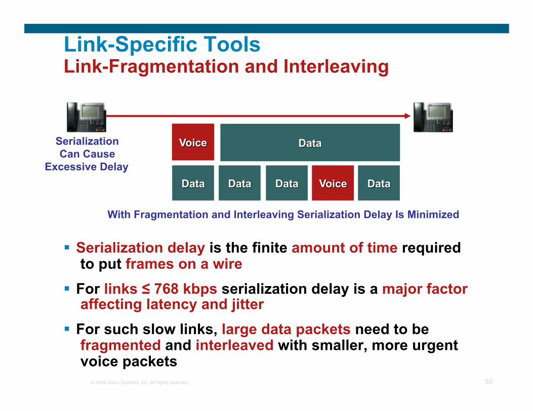
Link-Specific Tools Link-Fragmentation and Interleaving
Serialization delay is the finite amount of time required to put frames on a wire
For links ≤ 768 kbps serialization delay is a major factor affecting latency and jitter
For such slow links, large data packets need to be fragmented and interleaved with smaller, more urgent voice packets
Serialization Can Cause
Excessive Delay
With Fragmentation and Interleaving Serialization Delay Is Minimized
© 2008 Cisco Systems, Inc. All rights reserved. 53
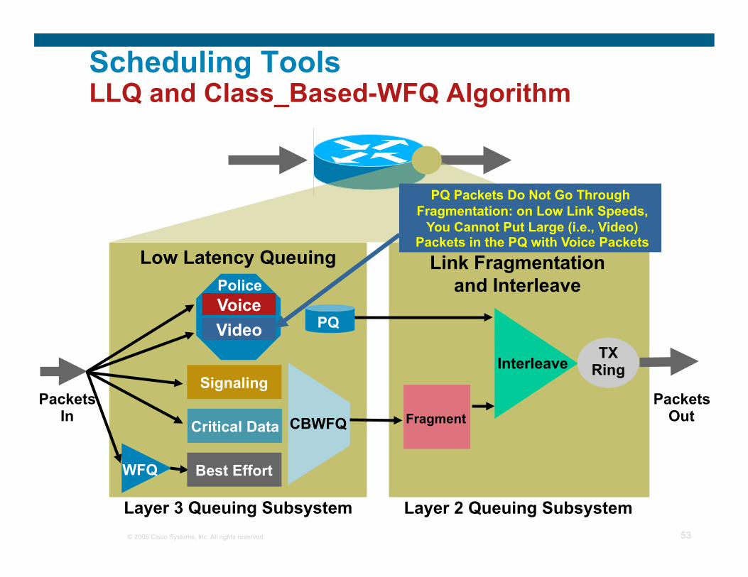
Voice
CBWFQ Fragment
Interleave
WFQ
Link Fragmentation and Interleave
Low Latency Queuing
Packets Out
Packets In
Police
Video PQ
Best Effort
Signaling
TX Ring
Critical Data
Layer 3 Queuing Subsystem Layer 2 Queuing Subsystem
PQ Packets Do Not Go Through Fragmentation: on Low Link Speeds,
You Cannot Put Large (i.e., Video) Packets in the PQ with Voice Packets
Scheduling Tools LLQ and Class_Based-WFQ Algorithm
© 2008 Cisco Systems, Inc. All rights reserved. 54
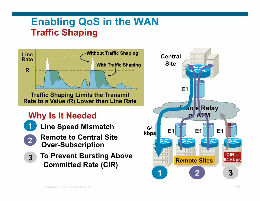
Enabling QoS in the WAN Traffic Shaping
Line Rate
R
Traffic Shaping Limits the Transmit Rate to a Value (R) Lower than Line Rate
Without Traffic Shaping
With Traffic Shaping
Why Is It Needed 1. Line Speed Mismatch 2. Remote to Central Site
Over-Subscription 3. To Prevent Bursting Above
Committed Rate (CIR)
1
2
3
Central Site
Frame Relay or ATM
E1
E1 E1 64 kbps E1
CIR = 64 kbps Remote Sites
3 2 1

© 2008 Cisco Systems, Inc. All rights reserved. 55
Link Capacity = (Min BW for Voice + Min BW for Video + Min BW for Data) / 0.75
Voice Is Not Free—Especially on Low Speed Links—Engineer the Network for Data, Voice, and Video
Sources of Trouble for VoIP
Sum of Traffic = 75%
Data Voice Routing
etc
Link Capacity
Video Voice/Video Control
LLQ = 33%
Provisioning

© 2008 Cisco Systems, Inc. All rights reserved. 56
Call Admission Control (CAC)

© 2008 Cisco Systems, Inc. All rights reserved. 57
Introduction Why Is Call Admission Control (CAC) Needed?
PSTN
Circuit-Switched Networks
Packet-Switched Networks
PBX
Physical Trunks
STOP
IP WAN Link
IP WAN Link’s LLQ Is Provisioned for Two Calls (Equivalent to Two “Virtual” Trunks)
Third Call Rejected
No Physical Limitation on IP Links; Third Call Can Go Through, but Voice Quality of All Calls Degrades Call Admission Control Blocks Third Call
IP WAN
Router/ Gateway
Call Control
© 2008 Cisco Systems, Inc. All rights reserved. 58
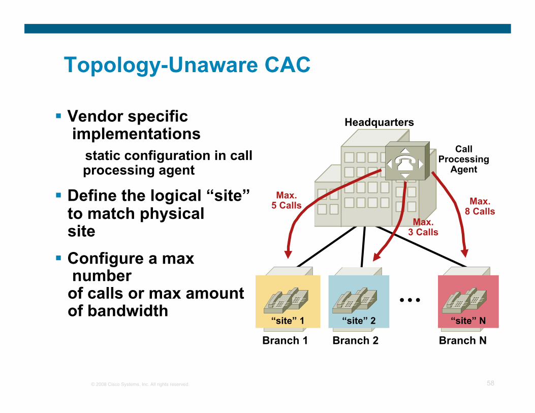
“site” N “site” 2 “site” 1
Topology-Unaware CAC
Vendor specific implementations
static configuration in call processing agent
Define the logical “site” to match physical site
Configure a max number of calls or max amount of bandwidth
...
Headquarters
Branch 1 Branch N Branch 2
Call Processing
Agent
Max. 5 Calls
Max. 3 Calls
Max. 8 Calls

© 2008 Cisco Systems, Inc. All rights reserved. 59
Topology-Unaware CAC
Simple hub-and-spoke topologies Simple MPLS-based topologies
Hub Site
Spoke Site 1
Spoke Site 2
Spoke Site N ...
Spoke Site 1
Spoke Site 2
Spoke Site N
Spoke Site Y
Spoke Site X
or SP-Provided MPLS IP WAN
Limited to:

© 2008 Cisco Systems, Inc. All rights reserved. 60
Topology-Unaware CAC “Real” Network Topology Aspects
Spoke Spoke
3rd Tier Hub
Spoke Spoke Spoke Spoke
3rd Tier Hub
2nd Tier Hub 2nd Tier
Hub
Spoke Spoke
Spoke Spoke Spoke Spoke
3rd Tier Hub
3rd Tier Hub
2nd Tier Hub 2nd Tier
Hub
Spoke Spoke Spoke Spoke Spoke Spoke
2nd Tier Hub
2nd Tier Hub
Dual-Homed Branch Sites
Redundant Hub Sites
Dual WAN Links
Fully Meshed Core
Hub-to-Hub Links
Multi-Tier Architectures
1st Tier Hub 1st Tier
Hub
1st Tier Hub
Core Core Multiple Paths
© 2008 Cisco Systems, Inc. All rights reserved. 61
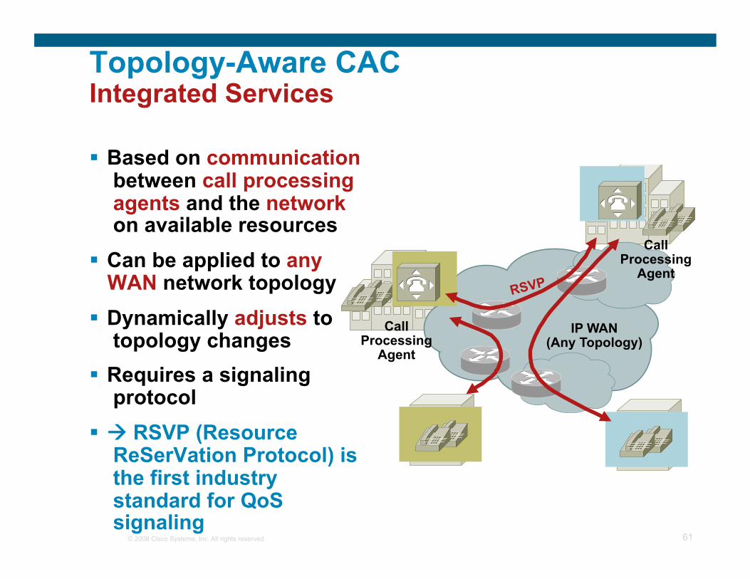
Topology-Aware CAC Integrated Services
Based on communication between call processing agents and the network on available resources
Can be applied to any WAN network topology
Dynamically adjusts to topology changes
Requires a signaling protocol
RSVP (Resource ReSerVation Protocol) is the first industry standard for QoS signaling
IP WAN (Any Topology)
RSVP
Call Processing
Agent
Call Processing
Agent

© 2008 Cisco Systems, Inc. All rights reserved. 62
Call Admission Control Principles Summary
Based on static configuration within call processing agent
Does not react to network topology changes (e.g. link failures)
Limited to simple topologies Limited to a single call
processing agent Examples: Cisco
CallManager® “static” locations, Cisco IOS®
gatekeeper zones
Based on real network resources
Requires a signaling protocol (RSVP)
Reacts to network topology changes
No topology limitation Can be used by different call
processing agents Examples: Cisco
CallManager RSVP-enabled locations, Cisco H.323 & SIP Voice gateways (AS5x00, 3800 etc), Cisco multiservice IP-IP gateway
Topology-Unaware CAC Topology-Aware CAC

© 2008 Cisco Systems, Inc. All rights reserved. 63
48 24 0
24
30 6
0
64
64 40
40
RSVP Principles
96
56
24 72 80
72 48
30 24
24 64 48 48
24
48
64 24
80 RSVP Bandwidth Pool Provisioned on Each
Router Interface with: ip rsvp bandwidth ...
If There Is Sufficient Bandwidth Throughout
the Network, the Reservation Succeeds
If Bandwidth on Any Link Throughout the Network Is
Not Sufficient, the Reservation Fails
Device 1
Device 2
RSVP Signaling Uses Same IP Route as the
Data Stream That Needs Reservation
Legend: = kbps
Remaining in RSVP Bandwidth Pool
56
RSVP-Unaware Routers Ignore and Forward All
RSVP Messages
Device 3
Device 4

© 2008 Cisco Systems, Inc. All rights reserved. 64
End devices CAC in H.323 & SIP
PSTN Cisco ASAP PSTN PSTN
GK
Gateway Resources: PSTN Side CAC
D S 0
DSPs
HDLC framers
D S 0
DSPs
HDLC framers
• Calls not delivered/accepted if any set of required resources are all in use
• Resources monitored – DS0s, DSPs, HDLC framers
• Hairpin, Play announcement or – Release with ‘Resource Unavailable’

© 2008 Cisco Systems, Inc. All rights reserved. 65
PSTN Cisco ASAP PSTN PSTN
GK
H.323 Gateway Resources: Network Side CAC
RAI
1 RAI - Resource Availability Indicator
D S 0
DSPs
0%
100% High Low
DS0
, DSP
re
sour
ces
• H.323: Gateway informs Gatekeeper if resource threshold exceeded using RAI1 – GK selects GW based on RAI status
• ICPIC2 or Delay & Loss thresholds
2 ICPIF - Calculated Planning Impairment Factor (ITU G.113)
End devices CAC in H.323 & SIP

© 2008 Cisco Systems, Inc. All rights reserved. 66
General Guidelines for QoS in the WAN
Use Low Latency Queuing (LLQ) anytime VoIP over the WAN is involved
Traffic shaping is a requirement for frame-relay/ATM environments
Use Fragmentation & Interleaving (LFI) techniques for all links below 768Kbps
Don’t use LFI for any video over IP applications Properly provision the WAN bandwidth Call admission control is a requirement where VoIP calls can
over-subscribe the provisioned BW Use cRTP carefully

© 2008 Cisco Systems, Inc. All rights reserved. 67
Agenda
Architectures using VoIP Recognizing Voice Quality Issues Classifying Voice Quality Attributes to Root
Cause Address Voice Quality by Implementing
Quality of Service (QoS) Echo Q & A

© 2008 Cisco Systems, Inc. All rights reserved. 68
Talker Echo
Talker echo occurs when a talker's speech energy, transmitted down the primary signal path, is coupled into the receive path from the far end; the talker then hears his/her own voice, delayed by the total echo path delay time; if the ‘echoed’ signal has sufficient amplitude and delay, the result can be annoying to the customer and interfere with the normal speech process; talker echo is usually a direct result of the 2-wire to 4-wire conversion that takes place through ‘hybrid’ transformers
John’s Voice
Echo of John’s Voice
Talker Echo (Most Common)
John San Jose
Jane New York
© 2008 Cisco Systems, Inc. All rights reserved. 69
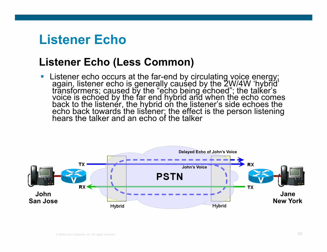
Listener Echo
Listener echo occurs at the far-end by circulating voice energy; again, listener echo is generally caused by the 2W/4W ‘hybrid’ transformers; caused by the “echo being echoed”; the talker’s voice is echoed by the far end hybrid and when the echo comes back to the listener, the hybrid on the listener’s side echoes the echo back towards the listener; the effect is the person listening hears the talker and an echo of the talker
John’s Voice
Delayed Echo of John’s Voice
Listener Echo (Less Common)
John San Jose
Jane New York

© 2008 Cisco Systems, Inc. All rights reserved. 70
Sources of Echo
+-
Tx
Rx
2-Wire Subscriber Loop
Xfmr
4-Wire Trunk Rs Rs ZL
Z?
Schematic of a Hybrid Circuit
Any Mismatch of Impedance vs. ZL Will Cause the Tx Signal to Appear
on Rx, This Is Hybrid Echo
Hybrid Echo
Earpiece
Microphone
Echo
Acoustic Echo

© 2008 Cisco Systems, Inc. All rights reserved. 71
What Makes Echo a Problem?
An analog leakage path between analog Tx and Rx paths
Sufficient delay in echo return for echo to be perceived as annoying
Sufficient echo amplitude to be perceived as annoying
For Echo to Be a Problem, all of the Following Conditions must Exist:

© 2008 Cisco Systems, Inc. All rights reserved. 72
Tail Circuit
Ecan Terminology
IP Network
Rin Rout
Sin
H(t)
y(t)
-
Echo Return Loss (ERL) is the echo level loss provided by the tail circuit. That is, if an speech signal entering the tail circuit from the network at a level of X dBm0 (i.e. Rout – above), the level of the echo coming back from the tail circuit into the Sin terminal of the echo canceller is (Rout – ERL) dBm0 i.e.
ERL
ERL = Rout - Sin

© 2008 Cisco Systems, Inc. All rights reserved. 73
Ecan Terminology Tail Circuit
IP Network
Rin Rout
Sin
H(t)
Sout
y(t)
-
ERLE Echo Return Loss Enhancement (ERLE) refers to the additional echo loss obtained through the operation of the echo canceller. An echo canceller is not a perfect device, and the best it can do is attenuate the level of the returning echo. ERLE is a measure of this echo attenuation through the echo canceller.
ERL
It is the difference is level (in dB) between the signal arriving from the tail circuit at the Sin terminal of the echo canceller and the level of the signal leaving the echo canceller (and entering the network) at the Sout terminal.
ERLE = Sin - Sout

© 2008 Cisco Systems, Inc. All rights reserved. 74
Ecan Terminology Tail Circuit
IP Network
Rin Rout
Sin Sout
H(t)
y(t)
-
ACOM
ERLE
ACOM (aka Acombined) is simply the total echo return loss seen across the Rin and Sout terminals of the echo canceller. It is the echo return loss seen by the network.
ERL
Rin
Sout
ACOM = ERL + ERLE

© 2008 Cisco Systems, Inc. All rights reserved. 75
Give the echo canceller enough information to distinguish between echo and normal conversation; the only parameters you have control over are:
Input level (input gain) Output level (output attenuation) Echo canceller coverage
E C A N
Tail Circuit
IP Network
Rin Rout
Sin Sout -
ACOM
ERLE
ERL
Output Attenuation
Input Gain
Eliminating Echo

© 2008 Cisco Systems, Inc. All rights reserved. 76
Rules of Thumb
Echo on one end is typically generated at other end
Bits don’t leak Echo is not introduced on digital links Introduced by 2 to 4 wire conversion in hybrid and impedance mismatch or via acoustic feedback
ERL must be 6dB for ECANs to engage Be careful setting echo-cancel coverage;
Longer coverage yields longer convergence time; Configure the coverage so that it is long enough to cover the worst-case for your environment, but no higher
© 2008 Cisco Systems, Inc. All rights reserved. 77
Q and A

© 2008 Cisco Systems, Inc. All rights reserved. 78
References
Echo
http://www.cisco.com/univercd/cc/td/doc/cisintwk/intsolns/voipsol/ea_isd.htm#91601
Voice Quality Degradation Symptoms http://www.cisco.com/warp/public/788/voice-qos/symptoms.html#clip
Quality of Service http://www.cisco.com/warp/public/732/Tech/qos/
IP SLA
http://www.cisco.com/en/US/products/sw/iosswrel/ps5207/products_configuration_guide_book09186a00802b2a6c.html
VoIP Troubleshooting Using “show call active voice” http://www.cisco.com/warp/public/788/voip/show_call_act_voice.html
© 2008 Cisco Systems, Inc. All rights reserved. 79