Managing Data Center Costs with Dell PowerEdge Energy ......Managing Data Center Costs with Dell...
13
Managing Data Center Costs with Dell PowerEdge Energy Smart Containment Rack Enclosures A Dell Technical White Paper Dell │ Data Center Infrastructure David L. Moss
Transcript of Managing Data Center Costs with Dell PowerEdge Energy ......Managing Data Center Costs with Dell...
Managing Data Center Costs with Dell PowerEdge Energy Smart Containment Rack Enclosures
A Dell Technical White Paper
Dell │ Data Center Infrastructure
David L. Moss
Managing Data Center Costs with Dell PowerEdge Energy Smart Containment Rack Enclosures
ii
THIS WHITE PAPER IS FOR INFORMATIONAL PURPOSES ONLY, AND MAY CONTAIN TYPOGRAPHICAL
ERRORS AND TECHNICAL INACCURACIES. THE CONTENT IS PROVIDED AS IS, WITHOUT EXPRESS OR
IMPLIED WARRANTIES OF ANY KIND.
© 2011 Dell Inc. All rights reserved. Reproduction of this material in any manner whatsoever without
the express written permission of Dell Inc. is strictly forbidden. For more information, contact Dell.
Dell, the DELL logo, the DELL badge, and PowerEdge are trademarks of Dell Inc. Other trademarks and
trade names may be used in this document to refer to either the entities claiming the marks and names
or their products. Dell Inc. disclaims any proprietary interest in trademarks and trade names other than
its own.
May 2011
Managing Data Center Costs with Dell PowerEdge Energy Smart Containment Rack Enclosures
3
Introduction Data center managers are faced with a multitude of options when considering the components that
make up their IT cooling infrastructure. Room/row/rack, air/water/refrigerant, contained or not,
passive/active…the list goes on. Dell believes there is no single right solution for everyone. The best
option is the one that fits the needs of the data center and is the most cost effective for both capital
and operating expenses (CapEx and OpEx). The Dell™ PowerEdge™ Energy Smart Containment Rack
Enclosure fits this description for many organizations.
Containment Gains Ground To operate efficiently, IT systems need a constant stream of cool air. IT inlets are almost exclusively
located on the front of the equipment. Concentrating the room venting in a cold aisle and orienting the
racks accordingly can take advantage of that concentrated delivery. Leveraging the hot/cold-aisle
orientation strategy can provide the proper airflow and enable dramatic increases in rack density.
This is a smart strategy, but it can be improved by using containment, which is a growing industry
trend. Without containment, the above-floor room dynamics are left to chance. Cold air is distributed
into the whole room, and in order to provide enough air to the installed equipment, it may be
necessary to overprovision the airflow. Additional air handlers are often employed, raising both OpEx
and CapEx. Cold air bypass mixes and cools hot return air. Hot air infiltration into the cold aisle creates
hot spots.
Why not contain either the delivery or the return? Containment provides intentional separation of the
cold supply from the hot return, resulting in better distribution of air and elimination of hot spots.
Whether using chimneys, curtains, hard panels, cold side, hot side, or the creation of a contained rear
cavity when installing a rear-door heat exchanger, the industry is embracing this strategy to improve
efficiency and reduce costs in the data center. It makes sense to cool the equipment, not the room.
If you have not implemented containment in your data center, you might want to consider some of the
potential energy benefits that are highlighted in previous Dell studies on containment.1,2 Even if you
are not concerned with energy, you might consider how containment can simplify your job. How often
have you been uncertain if you were putting new systems into a location with adequate cooling?
Containment can increase the certainty with which you deploy IT hardware.
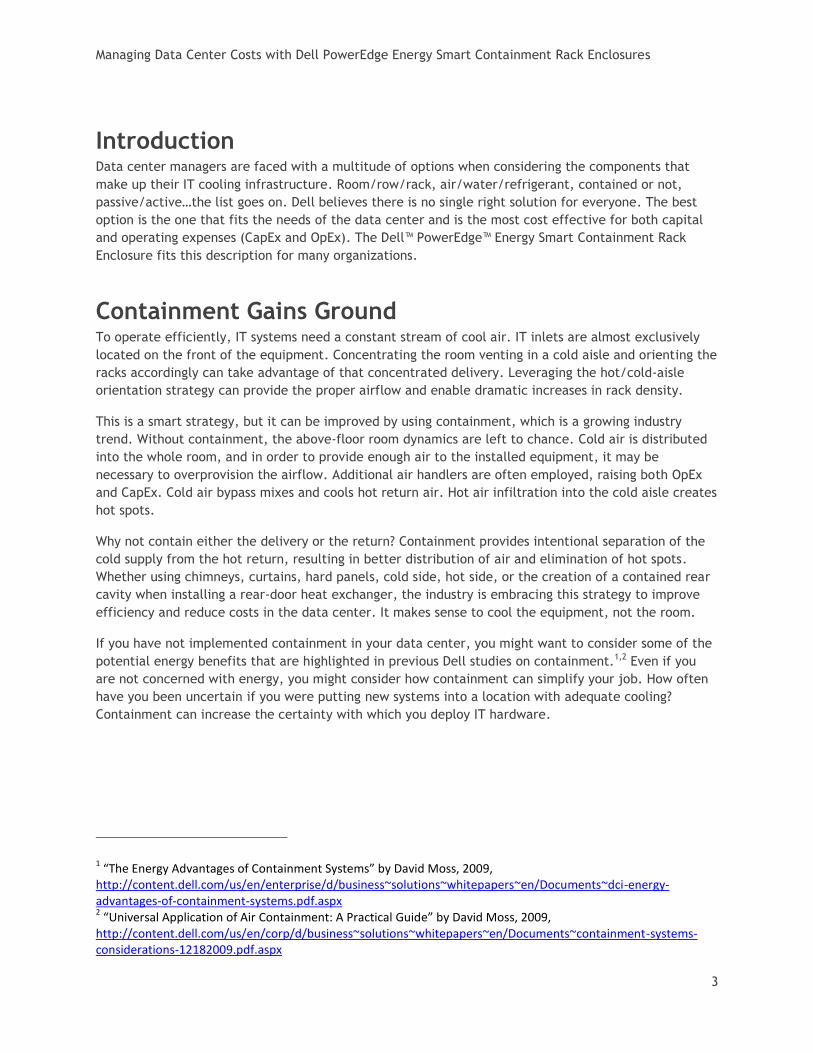
1 “The Energy Advantages of Containment Systems” by David Moss, 2009,
http://content.dell.com/us/en/enterprise/d/business~solutions~whitepapers~en/Documents~dci-energy-advantages-of-containment-systems.pdf.aspx 2 “Universal Application of Air Containment: A Practical Guide” by David Moss, 2009,
http://content.dell.com/us/en/corp/d/business~solutions~whitepapers~en/Documents~containment-systems-considerations-12182009.pdf.aspx
Managing Data Center Costs with Dell PowerEdge Energy Smart Containment Rack Enclosures
4
A New and Different Containment Solution Dell has developed a new containment solution to address the cooling concerns in the data center. The
PowerEdge Energy Smart Containment Rack Enclosure adds some additional parts to our standard rack
frame, transforming it into a stand-alone, front, cold-air containment system.
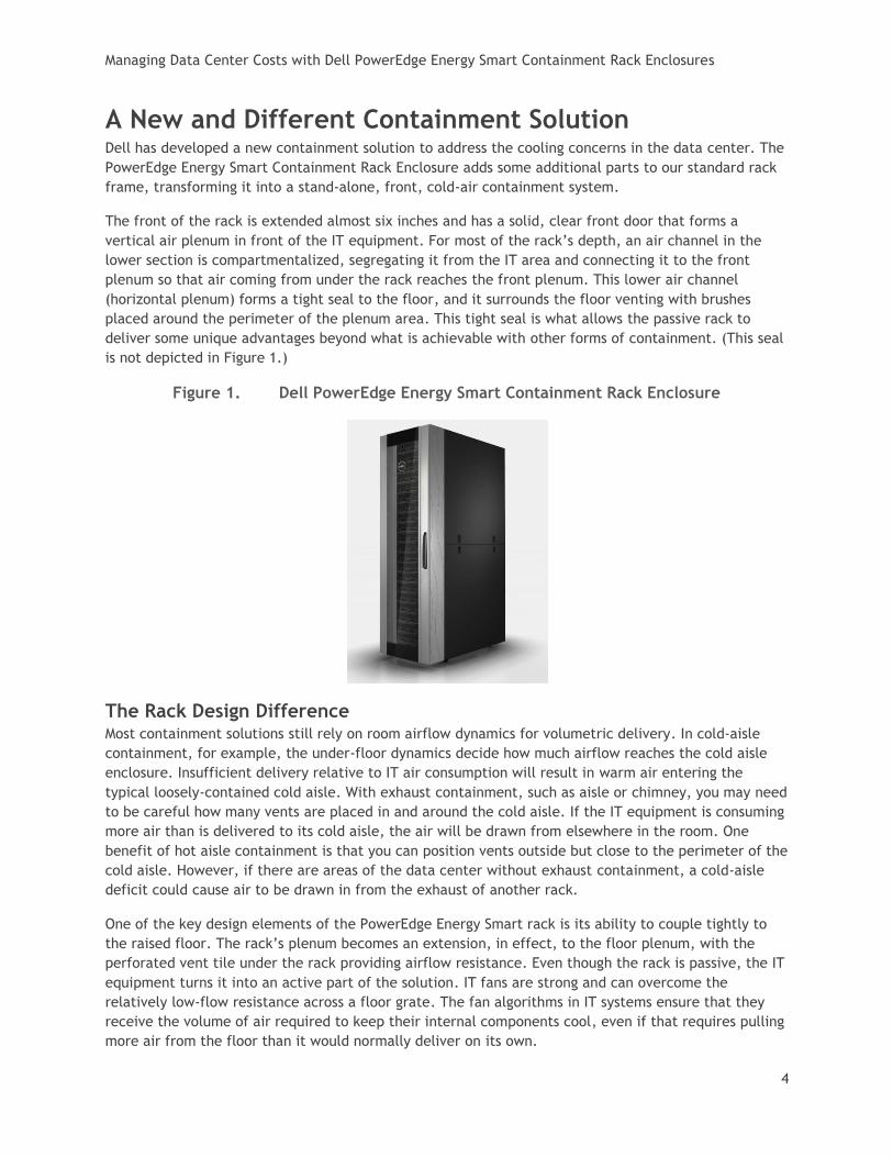
The front of the rack is extended almost six inches and has a solid, clear front door that forms a
vertical air plenum in front of the IT equipment. For most of the rack’s depth, an air channel in the
lower section is compartmentalized, segregating it from the IT area and connecting it to the front
plenum so that air coming from under the rack reaches the front plenum. This lower air channel
(horizontal plenum) forms a tight seal to the floor, and it surrounds the floor venting with brushes
placed around the perimeter of the plenum area. This tight seal is what allows the passive rack to
deliver some unique advantages beyond what is achievable with other forms of containment. (This seal
is not depicted in Figure 1.)
Figure 1. Dell PowerEdge Energy Smart Containment Rack Enclosure
The Rack Design Difference Most containment solutions still rely on room airflow dynamics for volumetric delivery. In cold-aisle
containment, for example, the under-floor dynamics decide how much airflow reaches the cold aisle
enclosure. Insufficient delivery relative to IT air consumption will result in warm air entering the
typical loosely-contained cold aisle. With exhaust containment, such as aisle or chimney, you may need
to be careful how many vents are placed in and around the cold aisle. If the IT equipment is consuming
more air than is delivered to its cold aisle, the air will be drawn from elsewhere in the room. One
benefit of hot aisle containment is that you can position vents outside but close to the perimeter of the
cold aisle. However, if there are areas of the data center without exhaust containment, a cold-aisle
deficit could cause air to be drawn in from the exhaust of another rack.
One of the key design elements of the PowerEdge Energy Smart rack is its ability to couple tightly to
the raised floor. The rack’s plenum becomes an extension, in effect, to the floor plenum, with the
perforated vent tile under the rack providing airflow resistance. Even though the rack is passive, the IT
equipment turns it into an active part of the solution. IT fans are strong and can overcome the
relatively low-flow resistance across a floor grate. The fan algorithms in IT systems ensure that they
receive the volume of air required to keep their internal components cool, even if that requires pulling
more air from the floor than it would normally deliver on its own.
Managing Data Center Costs with Dell PowerEdge Energy Smart Containment Rack Enclosures
5
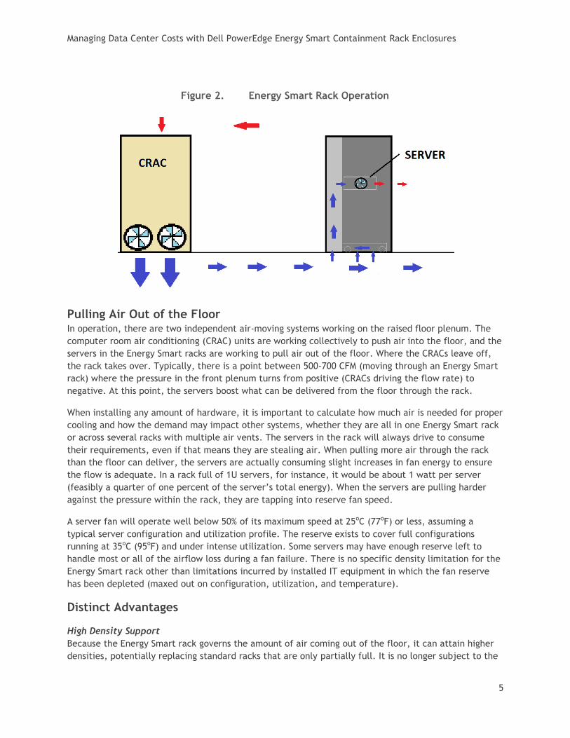
Figure 2. Energy Smart Rack Operation
Pulling Air Out of the Floor In operation, there are two independent air-moving systems working on the raised floor plenum. The
computer room air conditioning (CRAC) units are working collectively to push air into the floor, and the
servers in the Energy Smart racks are working to pull air out of the floor. Where the CRACs leave off,
the rack takes over. Typically, there is a point between 500-700 CFM (moving through an Energy Smart
rack) where the pressure in the front plenum turns from positive (CRACs driving the flow rate) to
negative. At this point, the servers boost what can be delivered from the floor through the rack.
When installing any amount of hardware, it is important to calculate how much air is needed for proper
cooling and how the demand may impact other systems, whether they are all in one Energy Smart rack
or across several racks with multiple air vents. The servers in the rack will always drive to consume
their requirements, even if that means they are stealing air. When pulling more air through the rack
than the floor can deliver, the servers are actually consuming slight increases in fan energy to ensure
the flow is adequate. In a rack full of 1U servers, for instance, it would be about 1 watt per server
(feasibly a quarter of one percent of the server’s total energy). When the servers are pulling harder
against the pressure within the rack, they are tapping into reserve fan speed.
A server fan will operate well below 50% of its maximum speed at 25oC (77oF) or less, assuming a
typical server configuration and utilization profile. The reserve exists to cover full configurations
running at 35oC (95oF) and under intense utilization. Some servers may have enough reserve left to
handle most or all of the airflow loss during a fan failure. There is no specific density limitation for the
Energy Smart rack other than limitations incurred by installed IT equipment in which the fan reserve
has been depleted (maxed out on configuration, utilization, and temperature).
Distinct Advantages
High Density Support
Because the Energy Smart rack governs the amount of air coming out of the floor, it can attain higher
densities, potentially replacing standard racks that are only partially full. It is no longer subject to the

Managing Data Center Costs with Dell PowerEdge Energy Smart Containment Rack Enclosures
6
dynamics under the floor. High densities can even be achieved in low pressure or congested areas:
shallow raised floors, wire-cluttered raised floors, and even dead spots can all be overcome by the
rack’s ability to adjust flow from the floor. These three challenges, along with other variables such as
raised floor pressure and the type of vent tile, all determine how hard the servers in the rack must
work relative to how much of a role the CRACs play.
There is typically a large difference between operation at 35oC and 25oC. This difference results in a
large fan reserve when running at 25oC or less. Dell plans to cover the density limitations and
considerations in more detail in subsequent documentation.
One target benchmark is 25 kW at 25oC. Because of the large fan reserve typical at 25oC or less, the
amount of fan reserve needed to counter pressure at flow rates typical of a 25 kW rack is less than the
fan reserve required to operate at 35oC. If the intended operating temperature is 25oC then a 25 kW
deployment should be achievable with most products, since the Energy Smart rack keeps temperatures
very consistent within the plenum.
No Density-Based Segregation
It is often common to see density zones in a data center. Denser equipment will be segregated and
treated separately from nominal racks. It may even be cooled by a completely separate strategy than
the remainder of the data center. With the Energy Smart rack, there is no need to segregate. A 2 kW
rack can easily coexist next to a 20 kW rack.
Energy Advantages
The Energy Smart rack enjoys the same advantages as other containment systems. The consistency of
airflow temperatures resulting from directly integrated containment can enable increases in facility
temperature resulting in dramatic energy advantages. Since it uses tight containment, it will control
temperatures more consistently than most aisle containment systems (especially curtains). This offers
increased savings opportunities. Furthermore, since containment helps correct the above-floor
dynamics, using the Energy Smart rack in a data center can also lead to utilizing fewer CRAC units and
reduced CRAC fan power if the recommended methods of control are in place.
At the system level, when containment corrects hot spots, there is an immediate drop in IT fan power
for an instant savings. The tighter containment and consistent temperature of the Energy Smart rack
may control the server temperatures better and result in a larger drop in fan power at a corrected hot
spot.
Simplified Deployment
The Energy Smart rack can be deployed quickly, anywhere in the room, on an individual basis or in
multiples. The rack is easily installed by positioning it over a ventilated tile. The data center room
does not even have to adopt the hot/cold aisle strategy since the cold delivery is isolated from the
room.
In contrast, aisle containment is built around a pod of racks aligned in multiples of two. It takes a
special design using customized lengths, some cut to fit, and on-site assembly to deploy a pod of aisle
containment. There are aisle containment pods in some of Dell’s data centers that may take months to
fill with IT systems. Until that time, racks sit empty of equipment and full of blanking panels. If using
row coolers, they may be left mostly off until enough hardware is deployed to require them.
Although the pod strategy is a great way to create a repetitive, predictable pattern of deployment, it
requires a significant up-front investment and doesn’t effectively leverage the “pay as you grow”
Managing Data Center Costs with Dell PowerEdge Energy Smart Containment Rack Enclosures
7
benefits of modularity. In contrast, the Energy Smart rack can be purchased and deployed one at a
time.
Although there are other rack products or containment solutions that may provide similar functionality,
only the Energy Smart rack offers a completely passive stand-alone containment system that pulls only
the amount of air the IT equipment consumes. It has no restrictions on the airflow CFM it can handle.
With no modifications needed to data center facilities for power, water, or refrigerant, the Energy
Smart rack is easier and more cost-effective to deploy.
Lower the Cost of Redundancy
The Energy Smart rack can help even out distribution deficits during a failure. Consider the example in
Figure 3.
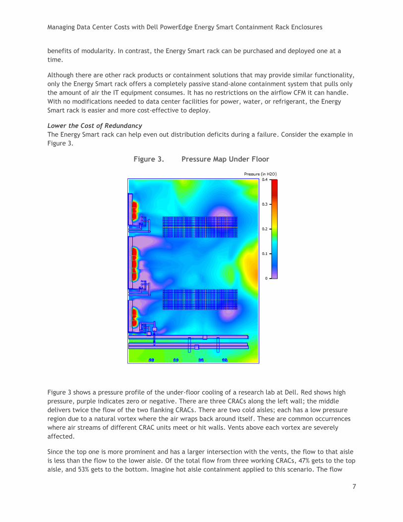
Figure 3. Pressure Map Under Floor
Figure 3 shows a pressure profile of the under-floor cooling of a research lab at Dell. Red shows high
pressure, purple indicates zero or negative. There are three CRACs along the left wall; the middle
delivers twice the flow of the two flanking CRACs. There are two cold aisles; each has a low pressure
region due to a natural vortex where the air wraps back around itself. These are common occurrences
where air streams of different CRAC units meet or hit walls. Vents above each vortex are severely
affected.
Since the top one is more prominent and has a larger intersection with the vents, the flow to that aisle
is less than the flow to the lower aisle. Of the total flow from three working CRACs, 47% gets to the top
aisle, and 53% gets to the bottom. Imagine hot aisle containment applied to this scenario. The flow
Managing Data Center Costs with Dell PowerEdge Energy Smart Containment Rack Enclosures
8
discrepancy probably would not matter. You could deploy just as much equipment in either aisle. Now
imagine cold aisle containment with this scenario. The captured upper aisle is only receiving 47% of the
flow. To deploy equal amounts of equipment in the upper aisle, you’d either have to increase the
venting in the upper aisle or decrease it in the lower aisle.
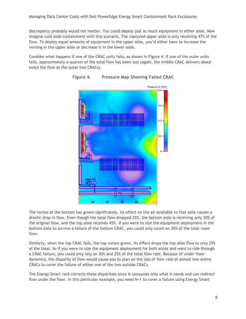
Consider what happens if one of the CRAC units fails, as shown in Figure 4. If one of the outer units
fails, approximately a quarter of the total flow has been lost (again, the middle CRAC delivers about
twice the flow as the outer two CRACs).
Figure 4. Pressure Map Showing Failed CRAC
The vortex at the bottom has grown significantly. Its effect on the air available to that aisle causes a
drastic drop in flow. Even though the total flow dropped 25%, the bottom aisle is receiving only 30% of
the original flow, and the top aisle receives 45%. If you were to size the equipment deployment in the
bottom aisle to survive a failure of the bottom CRAC, you could only count on 30% of the total room
flow.
Similarly, when the top CRAC fails, the top vortex grows. Its effect drops the top aisle flow to only 25%
of the total. So if you were to size the equipment deployment for both aisles and want to ride through
a CRAC failure, you could only rely on 30% and 25% of the total flow rate. Because of under-floor
dynamics, the disparity of flow would cause you to plan on the loss of flow rate of almost two entire
CRACs to cover the failure of either one of the two outside CRACs.
The Energy Smart rack corrects these disparities since it consumes only what it needs and can redirect
flow under the floor. In this particular example, you need N+1 to cover a failure using Energy Smart

Managing Data Center Costs with Dell PowerEdge Energy Smart Containment Rack Enclosures
9
racks; you would have to resort to N+2 to cover the same amount of equipment with cold aisle
containment.
Energy Benefits There are some interesting methods of CRAC control which can stretch CapEx and improve OpEx.
Coupled with the Energy Smart rack, the benefits are augmented. Under-floor static pressure control
for CRAC unit airflow is not yet common, but it is gaining in popularity and it is a perfect match for the
Energy Smart rack.
When the servers in the rack cause a change in flow out of the floor, they would cause a change in
under-floor pressure if the CRACs are constant speed or have temperature-based airflow control. If the
racks affect the pressure, and the CRACs are controlled by pressure, there is essentially a dynamic
coupling opportunity through the raised floor. When new racks are added, they take their required
consumption from the floor, and the CRACs can respond with additional air. If the racks scale
dynamically throughout the day, the CRACs can also respond.
Static pressure control can also help adjust to today’s hotter (or more efficient) IT equipment. In the
quest to save energy, today’s IT equipment consumes much less airflow per watt than its predecessors.
As a consequence, the temperature rise (delta-T) through the equipment is much higher. In fact, the
temperature rise is exactly proportional to the IT power (heat) and exactly inversely proportional to
the flow rate, per the equation below:
Q = m Cp ∆T
Q is the power (heat), m is the mass flow rate, Cp is the specific heat or the amount of heat the fluid
(air) can hold, and ∆T is the temperature rise (delta-T).
Several years ago, we might have used 25 CFM to cool 200 watts, whereas today we may be cooling 400
watts with the same 25 CFM. A 50oF delta-T is not impossible or unrealistic. Unless you purchase a high
delta-T cooling coil, it is typically designed for a delta-T of around 25 degrees which is quite a
mismatch with some IT equipment.
Figure 5. Temperature Rise for IT Equipment
∆T = 25°
∆T = 50°
How do you cool equipment with 50oF delta-T with infrastructure that only supports 25oF delta-T? The
easiest answer is probably the most prevalent: use twice as many CRAC units.
The extra air bypasses the IT systems and cools the return air and turns it into a net 25oF product. This
is obviously not the best answer. The CRAC unit can be stretched to an extent. As it hits 100%
utilization, the valve will not open any further, and the fans are running full speed. If return
Managing Data Center Costs with Dell PowerEdge Energy Smart Containment Rack Enclosures
10
temperature continues to climb, the unit can take on more heat and, in a sense, overdrive on tons. The
supply air temperature will start to rise at some point as well. By overdriving the unit, its delta-T may
be approaching a 50oF delta-T (but it is not likely to get close to this).
There is another way to further increase the CRAC’s delta-T and hopefully cool more equipment with
fewer CRAC units. The previous equation also works for CRAC units. If you can lower the mass flow for
the same heat absorption, you can raise the delta-T. Static pressure control is one way to do this, and
it is a perfect match for the Energy Smart rack. If CRAC units are operating based on return air
temperature, rather than static pressure control, they will still be compatible with the Energy Smart
rack, but they will not be able to respond to the server demands as effectively and will be less
efficient in terms of fan energy (which translates to higher costs of operation). Dell recommends using
static pressure control as the optimal configuration for CRACs being used with the Energy Smart rack.
The best way to illustrate this is using test data.
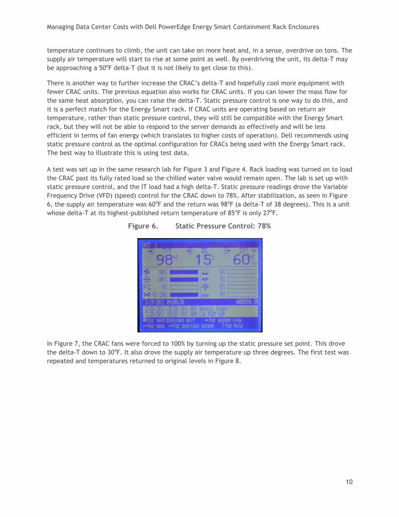
A test was set up in the same research lab for Figure 3 and Figure 4. Rack loading was turned on to load
the CRAC past its fully rated load so the chilled water valve would remain open. The lab is set up with
static pressure control, and the IT load had a high delta-T. Static pressure readings drove the Variable
Frequency Drive (VFD) (speed) control for the CRAC down to 78%. After stabilization, as seen in Figure
6, the supply air temperature was 60oF and the return was 98oF (a delta-T of 38 degrees). This is a unit
whose delta-T at its highest-published return temperature of 85oF is only 27oF.
Figure 6. Static Pressure Control: 78%
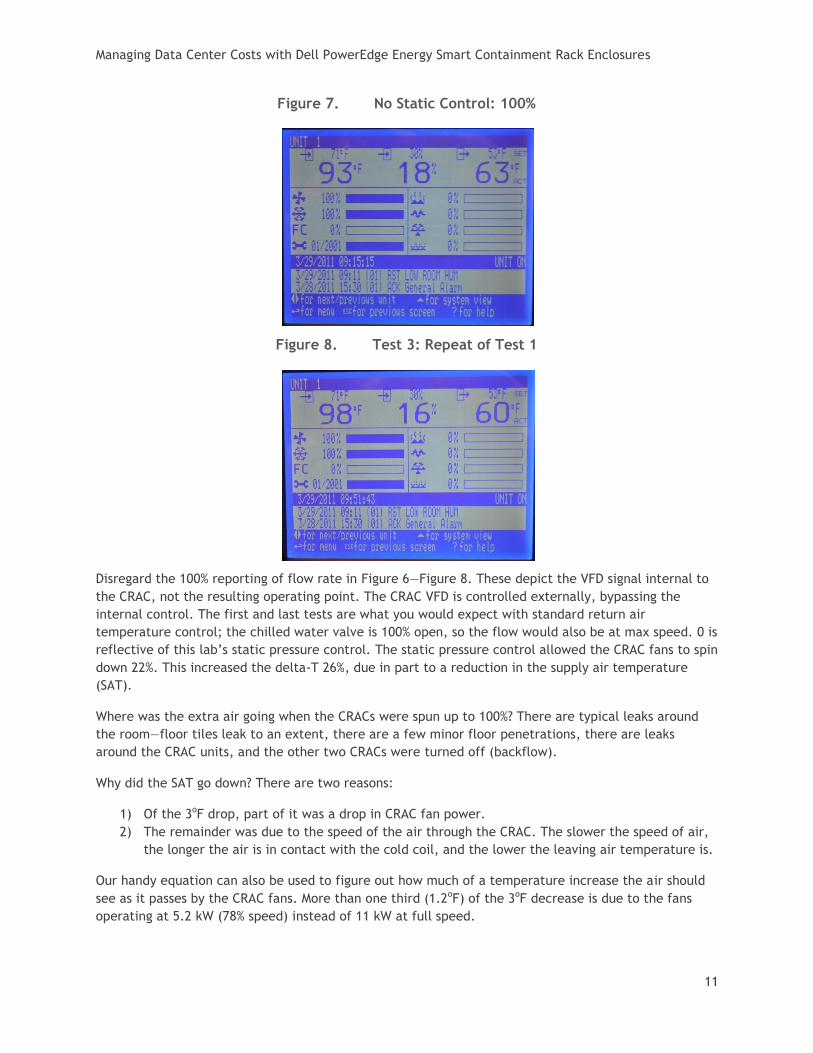
In Figure 7, the CRAC fans were forced to 100% by turning up the static pressure set point. This drove
the delta-T down to 30oF. It also drove the supply air temperature up three degrees. The first test was
repeated and temperatures returned to original levels in Figure 8.
Managing Data Center Costs with Dell PowerEdge Energy Smart Containment Rack Enclosures
11
Figure 7. No Static Control: 100%
Figure 8. Test 3: Repeat of Test 1
Disregard the 100% reporting of flow rate in Figure 6—Figure 8. These depict the VFD signal internal to
the CRAC, not the resulting operating point. The CRAC VFD is controlled externally, bypassing the
internal control. The first and last tests are what you would expect with standard return air
temperature control; the chilled water valve is 100% open, so the flow would also be at max speed. 0 is
reflective of this lab’s static pressure control. The static pressure control allowed the CRAC fans to spin
down 22%. This increased the delta-T 26%, due in part to a reduction in the supply air temperature
(SAT).
Where was the extra air going when the CRACs were spun up to 100%? There are typical leaks around
the room—floor tiles leak to an extent, there are a few minor floor penetrations, there are leaks
around the CRAC units, and the other two CRACs were turned off (backflow).
Why did the SAT go down? There are two reasons:
1) Of the 3oF drop, part of it was a drop in CRAC fan power.
2) The remainder was due to the speed of the air through the CRAC. The slower the speed of air,
the longer the air is in contact with the cold coil, and the lower the leaving air temperature is.
Our handy equation can also be used to figure out how much of a temperature increase the air should
see as it passes by the CRAC fans. More than one third (1.2oF) of the 3oF decrease is due to the fans
operating at 5.2 kW (78% speed) instead of 11 kW at full speed.
Managing Data Center Costs with Dell PowerEdge Energy Smart Containment Rack Enclosures
12
What can be done with that 3oF? Rather than operate 3oF cooler, it might be used to increase the room
temperature to save energy. Data from a Dell test for a chilled water facility suggested as high as 2.5%
was saved per degree in the cold region (sub-60oF air), but this diminished substantially as the air
temperature got higher. Over a range of temperatures from 57oF to 70oF, our data suggested an
average of 0.9% facility energy decrease per degree increase in SAT.
What role did the Energy Smart rack play? This test could have been performed with cold aisle
containment. With the right attention to venting in the cold aisle, the CRACs could have spun down
similarly and still delivered adequate flow to each of the two cold aisles in the data center. It would
have been a manual process to make sure each aisle was getting just enough flow (adjustment in the
number and types of vents), but the Energy Smart racks take care of themselves.
The use of static pressure control with the Energy Smart racks allows the CRAC units to continuously
seek the lowest energy state. This not only saves energy within the CRAC units, but it can lead to
efficiency savings with the changing of set points. It can also lead to capacity increases associated with
operating the CRAC units at a higher delta-T. This configuration may indeed have a positive effect on
both OpEx and CapEx.
There is one other benefit to the use of static pressure control, and that is in CRAC deployment
planning. Static pressure control enables the CRACs to reduce flow to a level that is approximately
what the IT racks consume. This is automatic in the case of the Energy Smart rack, but it can also be
achieved with manual adjustments in aisle containment. Since the flow is minimized, you can see what
is left over. If the CRAC units are running at 70%, for example, you know there is a 30% reserve. By
tracking the CRAC units’ flow rate as you add more IT equipment, you can project when it will run out.
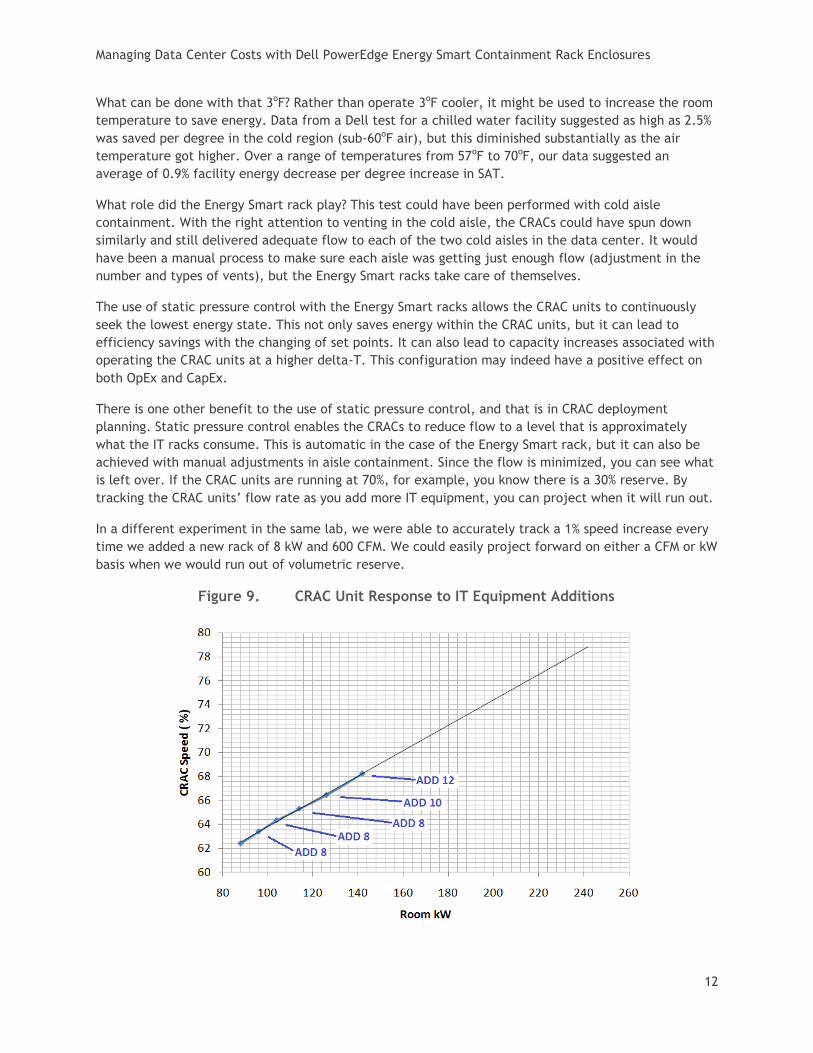
In a different experiment in the same lab, we were able to accurately track a 1% speed increase every
time we added a new rack of 8 kW and 600 CFM. We could easily project forward on either a CFM or kW
basis when we would run out of volumetric reserve.
Figure 9. CRAC Unit Response to IT Equipment Additions

Managing Data Center Costs with Dell PowerEdge Energy Smart Containment Rack Enclosures
13
Figure 9 shows that the CRAC response is quite granular and linear in responding to small additions of
IT equipment. We also failed either outside CRAC units, and in each case, the CRACs increased about
17%. This experiment stopped at 140 kW. The trend suggests reserve capacity for about another 120 kW
at which time the CRACs would be just over 80% and trending close to the point (83%) where
redundancy would be in question.
Conclusions Selecting the right cooling and containment solution for a data center can be a daunting exercise in
terms of balancing efficiency, utilization, and costs. The research evidence shown in this paper
demonstrates the potential savings in both capital and operating expenses and the energy benefits for
implementing containment by using the PowerEdge Energy Smart Containment Rack Enclosure together
with a static pressure cooling system in a data center.
For more information about this rack enclosure, refer to:
http://www.delltechcenter.com/page/Dell+PowerEdge+Energy+Smart+Containment+Rack+Enclosure.