Management - D-Link · management can be customized to suit the needs of the networks and the...
48
DGS-1510 Series Gigabit Ethernet SmartPro Switch Web UI Reference Guide 29 4. Management User Account Settings Password Encryption SNMP RMON Telnet/Web Session Timeout DHCP DNS File System Physical Stacking Virtual Stacking (SIM) D-Link Discovery Protocol User Account Settings This window is used to create and configure the user accounts. The active user account sessions can be viewed. There are several configuration options available in the Web User Interface (Web UI). The set of configuration options available to the user depends on the account’s Privilege Level. NOTE: By default, there is no user account created on the Switch. To view the following window, click Management > User Account Settings, as shown below: Figure 4-1 User Management Settings window The fields that can be configured are described below: Parameter Description User Name Enter the user account name here. This name can be up to 32 characters long. Privilege Enter the privilege level for this account here. This value must be between 1 and 15. Password Type Select the password type for this user account here. Options to choose from are None, Plain Text, and Encrypted.
Transcript of Management - D-Link · management can be customized to suit the needs of the networks and the...

DGS-1510 Series Gigabit Ethernet SmartPro Switch Web UI Reference Guide
29
4. Management
User Account Settings Password Encryption SNMP RMON Telnet/Web Session Timeout DHCP DNS File System Physical Stacking Virtual Stacking (SIM) D-Link Discovery Protocol
User Account Settings
This window is used to create and configure the user accounts. The active user account sessions can be viewed.
There are several configuration options available in the Web User Interface (Web UI). The set of configuration options available to the user depends on the account’s Privilege Level.
NOTE: By default, there is no user account created on the Switch.
To view the following window, click Management > User Account Settings, as shown below:
Figure 4-1 User Management Settings window
The fields that can be configured are described below:
Parameter Description
User Name Enter the user account name here. This name can be up to 32 characters long.
Privilege Enter the privilege level for this account here. This value must be between 1 and 15.
Password Type Select the password type for this user account here. Options to choose from are None, Plain Text, and Encrypted.

DGS-1510 Series Gigabit Ethernet SmartPro Switch Web UI Reference Guide
30
Password After selecting either Plain Text or Encrypted as the password type,
enter the password for this user account here.
Click the Apply button to accept the changes made.
Click the Delete button to remove the specified user account entry.
Enter a page number and click the Go button to navigate to a specific page when multiple pages exist.
After clicking the Session Table tab, the following page will appear.
Figure 4-2 Session Table window
A list of active user account session will be displayed.
Password Encryption
This window is used to configure whether to save the encryption of the password in the configuration file.
To view the following window, click Management > Password Encryption, as shown below:
Figure 4-3 Password Encryption window
The fields that can be configured are described below:
Parameter Description
Password Encryption State Select this option to enable or disable the encryption of the password before stored in the configuration file.
Click the Apply button to accept the changes made.
SNMP
Simple Network Management Protocol (SNMP) is an OSI Layer 7 (Application Layer) designed specifically for managing and monitoring network devices. SNMP enables network management stations to read and modify the settings of gateways, routers, switches, and other network devices. Use SNMP to configure system features for proper operation, monitor performance and detect potential problems in the Switch, switch group or network.

DGS-1510 Series Gigabit Ethernet SmartPro Switch Web UI Reference Guide
31
Managed devices that support SNMP include software (referred to as an agent), which runs locally on the device. A defined set of variables (managed objects) is maintained by the SNMP agent and used to manage the device. These objects are defined in a Management Information Base (MIB), which provides a standard presentation of the information controlled by the on-board SNMP agent. SNMP defines both the format of the MIB specifications and the protocol used to access this information over the network.
The Switch supports the SNMP versions 1, 2c, and 3. The three versions of SNMP vary in the level of security provided between the management station and the network device.
In SNMP v.1 and v.2, user authentication is accomplished using ‘community strings’, which function like passwords. The remote user SNMP application and the Switch SNMP must use the same community string. SNMP packets from any station that has not been authenticated are ignored (dropped).
The default community strings for the Switch used for SNMP v.1 and v.2 management access are:
public – Allows authorized management stations to retrieve MIB objects.
private – Allows authorized management stations to retrieve and modify MIB objects.
SNMPv3 uses a more sophisticated authentication process that is separated into two parts. The first part is to maintain a list of users and their attributes that are allowed to act as SNMP managers. The second part describes what each user on that list can do as an SNMP manager.
The Switch allows groups of users to be listed and configured with a shared set of privileges. The SNMP version may also be set for a listed group of SNMP managers. Thus, you may create a group of SNMP managers that are allowed to view read-only information or receive traps using SNMPv1 while assigning a higher level of security to another group, granting read/write privileges using SNMPv3.
Using SNMPv3 individual users or groups of SNMP managers can be allowed to perform or be restricted from performing specific SNMP management functions. The functions allowed or restricted are defined using the Object Identifier (OID) associated with a specific MIB. An additional layer of security is available for SNMPv3 in that SNMP messages may be encrypted. To read more about how to configure SNMPv3 settings for the Switch read the next section.
Traps
Traps are messages that alert network personnel of events that occur on the Switch. The events can be as serious as a reboot (someone accidentally turned OFF the Switch), or less serious like a port status change. The Switch generates traps and sends them to the trap recipient (or network manager). Typical traps include trap messages for Authentication Failure, Topology Change and Broadcast\Multicast Storm.
MIBs
The Switch in the Management Information Base (MIB) stores management and counter information. The Switch uses the standard MIB-II Management Information Base module. Consequently, values for MIB objects can be retrieved from any SNMP-based network management software. In addition to the standard MIB-II, the Switch also supports its own proprietary enterprise MIB as an extended Management Information Base. Specifying the MIB Object Identifier may also retrieve the proprietary MIB. MIB values can be either read-only or read-write.
The Switch incorporates a flexible SNMP management for the switching environment. SNMP management can be customized to suit the needs of the networks and the preferences of the network administrator. Use the SNMP V3 menus to select the SNMP version used for specific tasks.

DGS-1510 Series Gigabit Ethernet SmartPro Switch Web UI Reference Guide
32
The Switch supports the Simple Network Management Protocol (SNMP) versions 1, 2c, and 3. The administrator can specify the SNMP version used to monitor and control the Switch. The three versions of SNMP vary in the level of security provided between the management station and the network device.
SNMP settings are configured using the menus located on the SNMP V3 folder of the Web manager. Workstations on the network that are allowed SNMP privileged access to the Switch can be restricted with the Management Station IP Address menu.
SNMP Global Settings
This window is used to configure the SNMP global settings and trap settings.
To view the following window, click Management > SNMP > SNMP Global Settings, as shown below:
Figure 4-4 SNMP Global Settings window
The fields that can be configured for SNMP Global Settings are described below:
Parameter Description
SNMP Global State Select this option to enable or disable the SNMP feature.
SNMP Response Broadcast Request
Select this option to enable or disable the server to response to broadcast SNMP GetRequest packets.
SNMP UDP Port Enter the SNMP UDP port number.
Trap Source Interface Enter the interface whose IP address will be used as the source address for sending the SNMP trap packet.
The fields that can be configured for Trap Settings are described below:
Parameter Description
Trap Global State Select this option to enable or disable the sending of all or specific SNMP notifications.
SNMP Authentication Trap Tick this option to control the sending of SNMP authentication failure notifications. An authenticationFailuretrap is generated when the device receives an SNMP message that is not properly authenticated. The authentication method depends on the version of SNMP being used. For SNMPv1 or SNMPv2c, authentication failure occurs if packets are formed with an incorrect community string. For SNMPv3, authentication failure occurs if packets are formed with an incorrect

DGS-1510 Series Gigabit Ethernet SmartPro Switch Web UI Reference Guide
33
SHA/MD5 authentication key.
Port Link Up Tick this option to control the sending of port link up notifications. A linkup trap is generated when the device recognizes that one of the communication links has come up.
Port Link Down Tick this option to control the sending of port link down notifications. A linkDown trap is generated when the device recognizes a failure in one of the communication links.
Coldstart Tick this option to control the sending of SNMP coldStart notifications.
Warmstart Tick this option to control the sending of SNMP warmStart notifications.
Click the Apply button to accept the changes made.
SNMP Linkchange Trap Settings
This window is used to configure the SNMP link change trap settings.
To view the following window, click Management > SNMP > SNMP Linkchange Trap Settings, as
shown below:
Figure 4-5 SNMP Linkchange Trap Settings window
The fields that can be configured are described below:
Parameter Description
Unit Select the switch unit that will be used for this configuration here.
From Port / To Port Select the appropriate port range used for the configuration here.
Trap Sending Select this option to enable or disable the sending of the SNMP notification traps that is generated by the system.
Trap State Select this option to enable or disable the SNMP link change trap.
Click the Apply button to accept the changes made.

DGS-1510 Series Gigabit Ethernet SmartPro Switch Web UI Reference Guide
34
SNMP View Table Settings
This window is used to assign views to community strings that define which MIB objects can be accessed by a remote SNMP manager. The SNMP Group created with this table maps SNMP users (identified in the SNMP User Table) to the views created in the previous window.
To view the following window, click Management > SNMP > SNMP View Table Settings, as shown
below:
Figure 4-6 SNMP View Table Settings window
The fields that can be configured are described below:
Parameter Description
View Name Type an alphanumeric string of up to 32 characters. This is used to identify the new SNMP view being created.
Subtree OID Type the Object Identifier (OID) Subtree for the view. The OID identifies an object tree (MIB tree) that will be included or excluded from access by an SNMP manager.
View Type Select the view type here. Options to choose from are Included, and Excluded.
Included - Select to include this object in the list of objects that an
SNMP manager can access.
Excluded - Select to exclude this object from the list of objects that an
SNMP manager can access.
Click the Add button to add a new entry based on the information entered.
Click the Delete button to remove the specified entry.
SNMP Community Table Settings
This window is used to create an SNMP community string to define the relationship between the SNMP manager and an agent. The community string acts like a password to permit access to the agent on the Switch. One or more of the following characteristics can be associated with the community string:
An Access List of IP addresses of SNMP managers that are permitted to use the community string to gain access to the Switch’s SNMP agent.
Any MIB view that defines the subset of all MIB objects will be accessible to the SNMP community.

DGS-1510 Series Gigabit Ethernet SmartPro Switch Web UI Reference Guide
35
Read/write or read-only level permission for the MIB objects accessible to the SNMP community.
To view the following window, click Management > SNMP > SNMP Community Table Settings, as
shown below:
Figure 4-7 SNMP Community Table Settings window
The fields that can be configured are described below:
Parameter Description
Key Type Select the key type for the SNMP community. Options to choose from are Plain Text, and Encrypted.
Community Name Enter an alphanumeric string of up to 32 characters that is used to identify members of an SNMP community. This string is used like a password to give remote SNMP managers access to MIB objects in the Switch’s SNMP agent.
View Name Enter an alphanumeric string of up to 32 characters that is used to identify the group of MIB objects that a remote SNMP manager is allowed to access on the Switch. The view name must exist in the SNMP View Table.
Access Right Select the access right here. Options to choose from are Read Only, and Read Write.
Read Only - SNMP community members using the community string
created can only read the contents of the MIBs on the Switch.
Read Write - SNMP community members using the community string
created can read from, and write to the contents of the MIBs on the Switch.
IP Access-List Name Enter the name of the standard access list to control the user to use this community string to access to the SNMP agent.
Click the Add button to add a new entry based on the information entered.
Click the Delete button to remove the specified entry.
SNMP Group Table Settings
An SNMP Group created with this table maps SNMP users (identified in the SNMP User Table) to the views created in the previous window.
To view the following window, click Management > SNMP > SNMP Group Table Settings, as shown
below:
DGS-1510 Series Gigabit Ethernet SmartPro Switch Web UI Reference Guide
36
Figure 4-8 SNMP Group Table Settings window
The fields that can be configured are described below:
Parameter Description
Group Name Enter the group name of a maximum of 32 characters. The syntax is general string that does not allow space.
User-based Security Model Select the security model here. Options to choose from are SNMPv1, SNMPv2c, and SNMPv3.
SNMPv1 - Select to allow the group user to use the SNMPv1 security
model.
SNMPv2c - Select to allow the group user to use the SNMPv2c
security model.
SNMPv3 - Select to allow the group user to use the SNMPv3 security
model.
Security Level When selecting SNMPv3 in the User-based Security Model drop-
down list, this option is available.
NoAuthNoPriv - Specify that there will be no authorization and no
encryption of packets sent between the Switch and a remote SNMP manager.
AuthNoPriv - Specify that authorization will be required, but there will
be no encryption of packets sent between the Switch and a remote SNMP manager.
AuthPriv - Specify that authorization will be required, and that packets
sent between the Switch and a remote SNMP manger will be encrypted.
IP Address-List Name Enter the standard IP access control list (ACL) to associate with the group.
Read View Name Enter the read view name that the group user can access.
Write View Name Enter the write view name that the group user can access.
Notify View Name Enter a write view name that the group user can access. The notify view describes the object that can be reported its status via trap packets to the group user.
Click the Add button to add a new entry based on the information entered.
Click the Delete button to remove the specified entry.

DGS-1510 Series Gigabit Ethernet SmartPro Switch Web UI Reference Guide
37
SNMP Engine ID Local Settings
The Engine ID is a unique identifier used for SNMP V3 implementations on the Switch.
To view the following window, click Management > SNMP > SNMP Engine ID Local Settings, as shown
below:
Figure 4-9 SNMP Engine ID Local Settings window
The fields that can be configured are described below:
Parameter Description
Engine ID Enter the engine ID string with the maximum of 24 characters.
Click the Default button to revert the engine ID to the default.
Click the Apply button to accept the changes made.
SNMP User Table Settings
This window is used to configure and display the SNMP users that are currently configured on the Switch.
To view the following window, click Management > SNMP > SNMP User Table Settings, as shown
below:
The fields that can be configured are described below:
Parameter Description
User Name Enter an alphanumeric string of up to 32 characters. This is used to identify the SNMP users.

DGS-1510 Series Gigabit Ethernet SmartPro Switch Web UI Reference Guide
38
Group Name Enter the SNMP group name to which the user belongs. The syntax is general string that does not allow spaces.
SNMP Version Select the SNMP version. Options to choose from are v1, v2c, and v3.
SNMP V3 Encryption When selecting v3 in the SNMP Version drop-down list, this option is available. Options to choose from are None, Password, and Key.
Auth-Protocol When selecting v3 in the SNMP Version drop-down list, and selecting either Password or Key in the SNMP V3 Encryption drop-down list,
this option is available. Select the authentication level. Options to choose from are MD5, and SHA.
MD5 - Select to use the HMAC-MD5-96 authentication level. This field
will require the user to enter a password or a key.
SHA - Specify that the HMAC-SHA authentication protocol will be
used. This field will require the user to enter a password or a key.
Priv-Protocol When selecting v3 in the SNMP Version drop-down list, and selecting either Password or Key in the SNMP V3 Encryption drop-down list,
this option is available. Select the private protocol. Options to choose from are None, and DES56.
None - Specify that no authorization protocol is in use.
DES56 - Specify that DES 56-bit encryption is in use, based on the
CBC-DES (DES-56) standard. This field will require the user to enter a password or a key.
IP Address-List Name Enter the standard IP access control list (ACL) to associate with the user.
Click the Add button to add a new entry based on the information entered.
Click the Delete button to remove the specified entry.
SNMP Host Table Settings
This window is used to configure and display the recipient of the SNMP notification.
To view the following window, click Management > SNMP > SNMP Host Table Settings, as shown
below:
Figure 4-10 SNMP Host Table Settings
The fields that can be configured are described below:
Parameter Description

DGS-1510 Series Gigabit Ethernet SmartPro Switch Web UI Reference Guide
39
Host IPv4 Address Enter the IPv4 address of the SNMP notification host.
Host IPv6 Address Enter the IPv6 address of the SNMP notification host.
User-based Security Model Select the security model here. Options to choose from are SNMPv1, SNMPv2c, and SNMPv3.
SNMPv1 - Select to allow the group user to use the SNMPv1 security
model.
SNMPv2c - Select to allow the group user to use the SNMPv2c
security model.
SNMPv3 - Select to allow the group user to use the SNMPv3 security
model.
Security Level When selecting SNMPv3 in the User-based Security Model drop-
down list, this option is available.
NoAuthNoPriv - Specify that there will be no authorization and no
encryption of packets sent between the Switch and a remote SNMP manager.
AuthNoPriv - Specify that authorization will be required, but there will
be no encryption of packets sent between the Switch and a remote SNMP manager.
AuthPriv - Specify that authorization will be required, and that packets
sent between the Switch and a remote SNMP manger will be encrypted.
UDP Port Enter the UDP port number. The default trap UDP port number is 162. The range of UDP port numbers is from 0 to 65535. Some port numbers may conflict with other protocols.
Community String / SNMPv3 User Name
Enter the community string to be sent with the notification packet.
Click the Add button to add a new entry based on the information entered.
Click the Delete button to remove the specified entry.
RMON
RMON Global Settings
This window is used to enable or disable remote monitoring (RMON) for the rising and falling alarm trap feature for the SNMP function on the Switch.
To view the following window, click Management > RMON > RMON Global Settings, as shown below:
Figure 4-11 RMON Global Settings window
The fields that can be configured are described below:
Parameter Description
RMON Rising Alarm Trap Select this option to enable or disable the RMON Rising Alarm Trap

DGS-1510 Series Gigabit Ethernet SmartPro Switch Web UI Reference Guide
40
Feature.
RMON Falling Alarm Trap Select this option to enable or disable the RMON Falling Alarm Trap Feature.
Click the Apply button to accept the changes made.
RMON Statistics Settings
This window is used to configure and display the RMON statistics on the specified port.
To view the following window, click Management > RMON > RMON Statistics Settings, as shown below:
Figure 4-12 RMON Statistics Settings window
The fields that can be configured are described below:
Parameter Description
Unit Select the switch unit that will be used for this configuration here.
Port Select to choose the port.
Index Enter the RMON table index. The value is from 1 to 65535
Owner Enter the owner string. The string can be up to 127 characters.
Click the Add button to add a new entry based on the information entered.
Click the Delete button to remove the specified entry.
Click the Show Detail button to see the detail information of the specific port.
Enter a page number and click the Go button to navigate to a specific page when multiple pages exist.
After clicking the Show Detail button, the following window will appear.
Figure 4-13 RMON Statistics Table window
Click the Back button to return to the previous window.

DGS-1510 Series Gigabit Ethernet SmartPro Switch Web UI Reference Guide
41
RMON History Settings
This window is used to configure and display RMON MIB history statistics gathering on the specified port.
To view the following window, click Management > RMON > RMON History Settings, as shown below:
Figure 4-14 RMON History Settings window
The fields that can be configured are described below:
Parameter Description
Unit Select the switch unit that will be used for this configuration here.
Port Select to choose the port.
Index Enter the history group table index. The value is from 1 to 65535
Bucket Number Enter Specifies the number of buckets specified for the RMON collection history group of statistics. The range is from 1 to 65535. The default value is 50.
Interval Enter the time in seconds in each polling cycle. The range is from 1 to 3600.
Owner Enter the owner string. The string can be up to 127 characters.
Click the Add button to add a new entry based on the information entered.
Click the Delete button to remove the specified entry.
Click the Show Detail button to see the detail information of the specific port.
Enter a page number and click the Go button to navigate to a specific page when multiple pages exist.
After clicking the Show Detail button, the following window will appear.
Figure 4-15 RMON History Table window
Click the Back button to return to the previous window.
RMON Alarm Settings
This window is used to configure and display alarm entries to monitor an interface.
DGS-1510 Series Gigabit Ethernet SmartPro Switch Web UI Reference Guide
42
To view the following window, click Management > RMON > RMON Alarm Settings, as shown below:
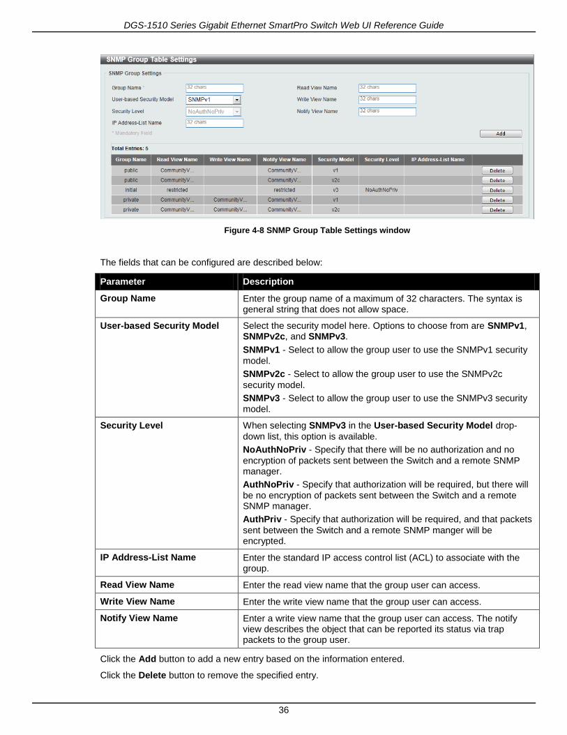
Figure 4-16 RMON Alarm Settings window
The fields that can be configured are described below:
Parameter Description
Index Enter the alarm index. The range is from 1 to 65535.
Interval Enter the interval in seconds for the sampling of the variable and checking against the threshold. The valid range is from 1 to 4294967295.
Variable Enter the object identifier of the variable to be sampled.
Type Select the monitoring type. Options to choose from are Absolute and Delta.
Rising Threshold Enter the rising threshold between 0 and 4294967295.
Falling Threshold Enter the rising threshold between 0 and 2147483647.
Rising Event Number Enter the index of the event entry that is used to notify the rising threshold crossing event. The valid range is from 1 to 65535. If not specified, no action is taken while crossing the ringing threshold.
Falling Event Number Enter the index of the event entry that is used to notify the falling threshold crossing event. The valid range is from 1 to 65535. If not specified, no action is taken while crossing the falling threshold.
Owner Enter the owner string up to 127 characters.
Click the Add button to add a new entry based on the information entered.
Click the Delete button to remove the specified entry.
Enter a page number and click the Go button to navigate to a specific page when multiple pages exist.
RMON Event Settings
This window is used to configure and display event entries.
To view the following window, click Management > RMON > RMON Event Settings, as shown below:

DGS-1510 Series Gigabit Ethernet SmartPro Switch Web UI Reference Guide
43
Figure 4-17 RMON Event Settings
The fields that can be configured are described below:
Parameter Description
Index Enter the index of the alarm entry between 1 and 65535.
Description Enter a description for the RMON event entry. The string is up to 127 characters long.
Type Select the RMON event entry type. Options to choose from are None, Log, Trap, and Log and Trap.
Community Enter the community string. The string can be up to 127 characters.
Owner Enter the owner string. The string can be up to 127 characters.
Click the Add button to add a new entry based on the information entered.
Click the Delete button to remove the specified entry.
Click the View Logs button to see the detail information of the specific port.
Enter a page number and click the Go button to navigate to a specific page when multiple pages exist.
After clicking the View Logs button, the following window will appear.
Figure 4-18 Event Logs Table window
Click the Back button to return to the previous window.
Telnet/Web
This window is used to configure Telnet and Web settings on the Switch.
To view the following window, click Management > Telnet/Web, as shown below:

DGS-1510 Series Gigabit Ethernet SmartPro Switch Web UI Reference Guide
44
Figure 4-19 Telnet/Web window
The fields that can be configured for Telnet Settings are described below:
Parameter Description
Telnet State Select this option to enable or disable the configuration through Telnet.
Port Enter the TCP port number used for Telnet management of the Switch. The “well-known” TCP port for the Telnet protocol is 23.
Click the Apply button to accept the changes made.
The fields that can be configured for Web Setting are described below:
Parameter Description
Web State Select this option to enable or disable the configuration through the web.
Port Enter the TCP port number used for Telnet management of the Switch. The “well-known” TCP port for the Telnet protocol is 80.
Click the Apply button to accept the changes made.
Session Timeout
This window is used to configure the session timeout.
To view the following window, click Management > Session Timeout, as shown below:
Figure 4-20 Session Timeout window
The fields that can be configured are described below:
Parameter Description
Web Session Timeout Enter the time in seconds of the web session timeout. Tick the Default

DGS-1510 Series Gigabit Ethernet SmartPro Switch Web UI Reference Guide
45
check box to return to the default setting. The value is from 60 to 36000 seconds. The default value is 180 seconds.
Console Session Timeout Enter the time in minutes of the web session timeout. Tick the Default
check box to return to the default setting. The value is from 0 to 1439 minutes. 0 means never timeout. The default value is 3 minutes.
Telnet Session Timeout Enter the time in minutes of the Telnet session timeout. Tick the Default check box to return to the default setting. The value is from 0
to 1439 minutes. 0 means never timeout. The default value is 3 minutes.
SSH Session Timeout Enter the time in minutes of the SSH session timeout. Tick the Default
check box to return to the default setting. The value is from 0 to 1439 minutes. 0 means never timeout. The default value is 3 minutes.
Click the Apply button to accept the changes made.
DHCP
Service DHCP
This window is used to configure the DHCP relay service on the Switch.
To view the following window, click Management > DHCP > Service DHCP, as shown below:
Figure 4-21 Service DHCP window
The fields that can be configured for Service DHCP are described below:
Parameter Description
Service DHCP State Select this option to enable or disable the DHCP relay service.
Click the Apply button to accept the changes made.
The fields that can be configured for Service IPv6 DHCP are described below:
Parameter Description
Service IPv6 DHCP State Select this option to enable or disable the IPv6 DHCP relay service.
Click the Apply button to accept the changes made.
DHCP Class Settings
This window is used to configure and display the DHCP class and the DHCP option matching pattern for the DCHP class.
To view the following window, click Management > DHCP > Service DHCP, as shown below:

DGS-1510 Series Gigabit Ethernet SmartPro Switch Web UI Reference Guide
46
Figure 4-22 DHCP Class Settings window
The fields that can be configured are described below:
Parameter Description
Class Name Enter the DHCP class name with a maximum of 32 characters.
Click the Apply button to accept the changes made.
Click the Edit button to modify the DHCP option matching pattern for the corresponding DCHP class.
Click the Delete button to remove the specified entry.
Enter a page number and click the Go button to navigate to a specific page when multiple pages exist.
After clicking the Edit button, the following window will appear.
Figure 4-23 DHCP Class Option Settings window
The fields that can be configured are described below:
Parameter Description
Option Enter the DHCP option number. The range is from 1 to 255.
Hex Enter the hex pattern of the specified DHCP option. Tick the * check
box not to match the remaining bits of the option.
Bitmask Enter the hex bit mask for masking of the pattern. The masked pattern bits will be matched. If not specified, all bits entered in Hex will be
checked.
Click the Apply button to accept the changes made.
Click the Delete button to remove the specified entry.
Click the Back button to return to the previous window.

DGS-1510 Series Gigabit Ethernet SmartPro Switch Web UI Reference Guide
47
DHCP Relay
DHCP Relay Global Settings
This window is used to configure the smart relay feature of the DHCP relay agent.
To view the following window, click Management > DHCP > DHCP Relay > DHCP Relay Global Settings, as shown below:
Figure 4-24 DHCP Relay Global Settings window
The fields that can be configured are described below:
Parameter Description
DCHP Smart Relay State Select this option to enable or disable the DHCP smart relay.
Click the Apply button to accept the changes made.
DHCP Relay Pool Settings
This window is used to configure and display the DHCP relay pool on a DHCP relay agent.
To view the following window, click Management > DHCP > DHCP Relay > DHCP Relay Pool Settings,
as shown below:
Figure 4-25 DHCP Relay Pool Settings window
The fields that can be configured are described below:
Parameter Description
Pool Name Enter the address pool name with a maximum of 32 characters.
Click the Apply button to accept the changes made.
Click the Edit button to modify the corresponding information of the specific DHCP pool.
Click the Delete button to remove the specified entry.
Enter a page number and click the Go button to navigate to a specific page when multiple pages exist.
After clicking the Edit button under Source, the following window will appear.

DGS-1510 Series Gigabit Ethernet SmartPro Switch Web UI Reference Guide
48
Figure 4-26 DHCP Relay Pool Source Settings window
The fields that can be configured are described below:
Parameter Description
Source IP Address Enter the source subnet of client packets.
Subnet Mask Enter the network mask of the source subnet.
Click the Apply button to accept the changes made.
Click the Delete button to remove the specified entry.
Click the Back button to return to the previous window.
After clicking the Edit button under Destination, the following window will appear.
Figure 4-27 DHCP Relay Pool Destination Settings window
The fields that can be configured are described below:
Parameter Description
Relay Destination Enter the relay destination DHCP server IP address.
Click the Apply button to accept the changes made.
Click the Delete button to remove the specified entry.
Click the Back button to return to the previous window.
After clicking the Edit button under Class, the following window will appear.

DGS-1510 Series Gigabit Ethernet SmartPro Switch Web UI Reference Guide
49
Figure 4-28 DHCP Relay Pool Class Settings window
The fields that can be configured are described below:
Parameter Description
Class Name Select the DHCP class name.
Click the Apply button to accept the changes made.
Click the Edit button to edit more information.
Click the Delete button to remove the specified entry.
Click the Back button to return to the previous window.
After clicking the Edit button, the following window will appear.
Figure 4-29 DHCP Relay Pool Class Edit Settings window
The fields that can be configured are described below:
Parameter Description
Relay Target Enter the DHCP relay target for relaying packets that matches the value pattern of the option defined in the DHCP class.
Click the Apply button to accept the changes made.
Click the Delete button to remove the specified entry.
Click the Back button to return to the previous window.
DHCP Relay Information Settings
This window is used to configure and display the DHCP relay information.
To view the following window, click Management > DHCP > DHCP Relay > DHCP Relay Information Settings, as shown below:

DGS-1510 Series Gigabit Ethernet SmartPro Switch Web UI Reference Guide
50
Figure 4-30 DHCP Relay Information Settings window
The fields that can be configured are described below:
Parameter Description
Information Trust All Select this option to enable or disable the DHCP relay agent to trust the IP DHCP relay information for all interfaces.
Information Check Select this option to enable or disable the DHCP relay agent to validate and remove the relay agent information option in the received DHCP reply packet.
Information Policy Select the Option 82 re-forwarding policy for the DHCP relay agent. Options to choose from are Keep, Drop, and Replace.
Keep - Select to discard the packet that already has the relay option.
Drop - Select that the DHCP request packet that already has the relay
option is left unchanged and directly relayed to the DHCP server.
Replace - Select that the DHCP request packet that already has the
relay option will be replaced by a new option.
Information Option Select this option to enable or disable the insertion of relay agent information (Option 82) during the relay of DHCP request packets.
Click the Apply button to accept the changes made.
Click the Edit button to modify the corresponding interface.
Enter a page number and click the Go button to navigate to a specific page when multiple pages exist.
DHCP Relay Information Option Format Settings
This window is used to configure and display the DHCP information format.
To view the following window, click Management > DHCP > DHCP Relay > DHCP Relay Information Option Format Settings, as shown below:

DGS-1510 Series Gigabit Ethernet SmartPro Switch Web UI Reference Guide
51
Figure 4-31 DHCP Relay Information Option Format Settings window
The fields that can be configured for DHCP Relay Information Option Format Global are described
below:
Parameter Description
Information Format Remote ID
Select the DHCP information remote ID sub-option. Options to choose from are Default, User Define, Vendor2, and Vendor3.
Default - Select to use the Switch's system MAC address as the
remote ID.
User Define - Select to use a user-defined remote ID. Enter the user-
defined string with the maximum of 32 characters in the text box.
Vendor2 - Select to use vender 2 as the remote ID.
Vendor3 - Select to use vender 3 as the remote ID.
Information Format Circuit ID Select the DHCP information circuit ID sub-option. Options to choose from are Default, User Define, Vendor1, Vendor2, Vendor3, Vendor4, Vendor5, and Vendor6.
Default - Select to use the default circuit ID sub-option.
User Define - Select to use a user-defined circuit ID. Enter the user-
defined string with the maximum of 32 characters in the text box.
Vendor1 - Select to use vender 1 as the circuit ID.
Vendor2 - Select to use vender 2 as the circuit ID.
Vendor3 - Select to use vender 3 as the circuit ID.
Vendor4 - Select to use vender 4 as the circuit ID.
Vendor5 - Select to use vender 5 as the circuit ID.
Vendor6 - Select to use vender 6 as the circuit ID.
Click the Apply button to accept the changes made.
The fields that can be configured for DHCP Relay Information Option Format Type are described below:

DGS-1510 Series Gigabit Ethernet SmartPro Switch Web UI Reference Guide
52
Parameter Description
Unit Select the switch unit that will be used for this configuration here.
From Port / To Port Select the appropriate port range used for the configuration here.
Format Select the DHCP information circuit ID format. Option to choose from is Vendor3.
Type Select the DHCP information circuit ID format typ. Options to choose from are Remote ID, and Circuit ID.
Value Enter the vendor-defined string.
Click the Apply button to accept the changes made.
DHCP Local Relay VLAN
This window is used to configure local relay on a VLAN or a group of VLANs.
To view the following window, click Management > DHCP > DHCP Relay > DHCP Local Relay VLAN,
as shown below:
Figure 4-32 DHCP Local Relay VLAN window
The fields that can be configured are described below:
Parameter Description
DHCP Local Relay VID List Enter the VLAN ID for DHCP local relay. Tick the All VLANs check
box to select all VLANs.
State Select this option to enable or disable the DHCP local relay on the specific VLAN(s).
Click the Apply button to accept the changes made.
DHCPv6 Relay
DHCPv6 Relay Global Settings
This window is used to configure the DHCPv6 relay remote ID.
To view the following window, click Management > DHCP > DHCPv6 Relay > DHCPv6 Relay Global Settings, as shown below:

DGS-1510 Series Gigabit Ethernet SmartPro Switch Web UI Reference Guide
53
Figure 4-33 DHCPv6 Relay Global Settings window
The fields that can be configured are described below:
Parameter Description
IPv6 DHCP Relay Remote ID Format
Select to choose the sub-type of the remote ID. Options to choose from are Default, CID with User Define, and User Define.
IPv6 DHCP Relay Remote ID UDF
Select to choose the User Define Field (UDF) for remote ID. Options to choose from are ASCII, and Hex.
ASCII - Select to enter the ASCII string with a maximum of 128
characters in the text box.
HEX - Select to enter the hexadecimal string with a maximum of 256
characters in the text box.
IPv6 DHCP Relay Remote ID Policy
Select to choose Option 37 forwarding policy for the DHCPv6 relay agent. Options to choose from are Keep, and Drop.
Keep - Select to discard the packet that already has the relay agent
Remote-ID Option 37.
Drop - Select that the DHCPv6 request packet that already has the
relay agent Remote-ID option is left unchanged and directly relayed to the DHCPv6 server.
IPv6 DHCP Relay Remote ID Option
Select this option to enable or disable the insertion of the relay agent remote ID Option 37 during the relay of DHCP for IPv6 request packets.
Click the Apply button to accept the changes made.
DHCPv6 Relay Interface Settings
This window is used to configure and display the DHCPv6 relay interface settings.
To view the following window, click Management > DHCP > DHCPv6 Relay > DHCPv6 Relay Interface Settings, as shown below:
Figure 4-34 DHCPv6 Relay Interface Settings window
DGS-1510 Series Gigabit Ethernet SmartPro Switch Web UI Reference Guide
54
The fields that can be configured are described below:
Parameter Description
Interface VLAN Enter the VLAN from 1 to 4094 for DHCPv6 relay.
Destination IPv6 Address Enter the DHCPv6 relay destination address.
Output Interface VLAN Enter the output interface for the relay destination.
Click the Apply button to accept the changes made.
Click the Find button to locate a specific entry based on the information entered.
Click the Delete button to remove the specified entry.
Enter a page number and click the Go button to navigate to a specific page when multiple pages exist.
DHCP Auto Configuration
This window is used to configure the DHCP auto-configuration function.
To view the following window, click Management > DHCP > DHCP Auto Configuration, as shown below:
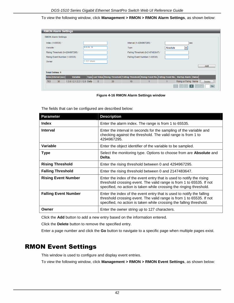
Figure 4-35 DHCP Auto Configuration window
The fields that can be configured are described below:
Parameter Description
Auto Configuration State Select this option to enable or disable the auto-configuration function.
Click the Apply button to accept the changes made.
DNS
Computer users usually prefer to use text names for computers for which they may want to open a connection. Computers themselves, require 32 bit IP addresses. Somewhere, a database of network devices’ text names and their corresponding IP addresses must be maintained.
The Domain Name System (DNS) is used to map names to IP addresses throughout the Internet and has been adapted for use within intranets. For two DNS servers to communicate across different subnets, the DNS Relay of the Switch must be used. The DNS servers are identified by IP addresses.
Mapping Domain Names to Addresses
Name-to-address translation is performed by a program called a Name server. The client program is called a Name resolver. A Name resolver may need to contact several Name servers to translate a name to an address.

DGS-1510 Series Gigabit Ethernet SmartPro Switch Web UI Reference Guide
55
The Domain Name System (DNS) servers are organized in a somewhat hierarchical fashion. A single server often holds names for a single network, which is connected to a root DNS server - usually maintained by an ISP.
Domain Name Resolution
The domain name system can be used by contacting the name servers one at a time, or by asking the domain name system to do the complete name translation. The client makes a query containing the name, the type of answer required, and a code specifying whether the domain name system should do the entire name translation, or simply return the address of the next DNS server if the server receiving the query cannot resolve the name.
When a DNS server receives a query, it checks to see if the name is in its sub domain. If it is, the server translates the name and appends the answer to the query, and sends it back to the client. If the DNS server cannot translate the name, it determines what type of name resolution the client requested. A complete translation is called recursive resolution and requires the server to contact other DNS servers until the name is resolved. Iterative resolution specifies that if the DNS server cannot supply an answer, it returns the address of the next DNS server the client should contact.
Each client must be able to contact at least one DNS server, and each DNS server must be able to contact at least one root server.
The address of the machine that supplies domain name service is often supplied by a DHCP or BOOTP server, or can be entered manually and configured into the operating system at startup.
DNS Global Settings
This window is used to configure the DNS global settings.
To view the following window, click Management > DNS > DNS Global Settings, as shown below:
Figure 4-36 DNS Global Settings window
The fields that can be configured are described below:
Parameter Description
IP DNS Lookup Static State Select this option to enable or disable the lookup of static entries before asking the name server.
IP DNS Lookup Cache State Select this option to enable or disable the lookup of the dynamic cache before asking the name server.
IP Domain Lookup Select this option to enable or disable the DNS to carry out the domain name resolution.
IP Name Server Timeout Enter the maximum time to wait for a response from a specified name

DGS-1510 Series Gigabit Ethernet SmartPro Switch Web UI Reference Guide
56
server. This value is between 1 and 60 seconds.
IP DNS Server Select this option to enable or disable the DNS caching name server function.
Click the Apply button to accept the changes made.
DNS Name Server Settings
This window is used to configure and display the IP address of a domain name server.
To view the following window, click Management > DNS > DNS Name Server Settings, as shown below:
Figure 4-37 DNS Name Server Settings window
The fields that can be configured are described below:
Parameter Description
Name Server IPv4 Select and enter the IPv4 address of the DNS server.
Name Server IPv6 Select and enter the IPv6 address of the DNS server.
Click the Apply button to accept the changes made.
Click the Delete button to remove the specified entry.
DNS Host Settings
This window is used to configure the static mapping entry for the host name and the IP address in the host table.
To view the following window, click Management > DNS > DNS Host Settings, as shown below:
Figure 4-38 DNS Host Settings window

DGS-1510 Series Gigabit Ethernet SmartPro Switch Web UI Reference Guide
57
The fields that can be configured are described below:
Parameter Description
Host Name Enter the host name of the equipment.
IP Address Select and enter the IPv4 address of the equipment.
IPv6 Address Select and enter the IPv6 address of the equipment.
Click the Apply button to accept the changes made.
Click the Delete button to remove the specified entry.
File System
Why use flash file system:
In old switch system, the firmware, configuration and log information are saved in a flash with fixed addresses and size. This means that the maximum configuration file can only be 2Mb, and even if the current configuration is only 40Kb, it will still take up 2Mb of flash storage space. The configuration file number and firmware numbers are also fixed. A compatible issue will occur in the event that the configuration file or firmware size exceeds the originally designed size.
Flash File System in our system:
The Flash File System is used to provide the user with flexible file operation on the Flash. All the firmware, configuration information and system log information are stored in the Flash as files. This means that the Flash space taken up by all the files are not fixed, it is the real file size. If the Flash space is enough, the user could download more configuration files or firmware files and use commands to display Flash file information, rename file names, and delete it. Furthermore, the user can also configure the boot up runtime image or the running configuration file if needed.
To view this window, click Management > File System as shown below:
Figure 4-39 File System window
The fields that can be configured are described below:
Parameter Description
Unit Select the switch unit that will be used for this configuration here.
Path Enter the path string
Click the Go button to navigate to the path entered.
Click the C: hyperlink to navigate the C: drive

DGS-1510 Series Gigabit Ethernet SmartPro Switch Web UI Reference Guide
58
After clicking the C: hyperlink, the following window will appear:
Figure 4-40 File System - Search for Drive window
Click the Previous button to return to the previous window.
Click the Create Directory to create a new directory within the file system of the Switch.
Click the Copy button to copy a specific file to the Switch.
Click the Boot Up button to set a specific runtime image as the boot up image.
Click the Rename button to rename a specific file’s name.
Click the Delete button to remove a specific file from the file system.
Click the Copy button to see the following window.
Figure 4-41 File System - Copy window
When copying a file to the file system of this switch, the user must enter the Source and Destination path. Tick the Replace check box to replace the current running configuration with the indicated
configuration file.
Click the Apply button to initiate the copy.
Click the Cancel button the discard the process.
Physical Stacking
The Switch supports switch stacking, where a set of 6 switches can be combined to be managed by one IP address through Telnet, the Web User Interface, the RJ45 console port, or through SNMP. Each

DGS-1510 Series Gigabit Ethernet SmartPro Switch Web UI Reference Guide
59
switch of this series has two stacking ports located at the front of the device, which can be used to connect other devices and make them stack together. After adding these stacking ports, the user may connect these ports together using fiber cables or Direct Attach Cables (DAC) in one of two possible topologies.
Duplex Chain – As shown in Figure 4-42, The Duplex Chain topology stacks switches together in a
chain-link format. Using this method, data transfer is only possible in one direction and if there is a break in the chain, then data transfer will obviously be affected.
Duplex Ring – As shown in Figure 4-43, the Duplex Ring stacks switches in a ring or circle format where
data can be transferred in two directions. This topology is very resilient due to the fact that if there is a break in the ring, data can still be transferred through the stacking cables between switches in the stack.
Figure 4-42 Switches stacked in a Duplex Chain

DGS-1510 Series Gigabit Ethernet SmartPro Switch Web UI Reference Guide
60
Figure 4-43 Switches stacked in a Duplex Ring
Within each of these topologies, each switch plays a role in the Switch stack. These roles can be set by the user per individual Switch, or if desired, can be automatically determined by the Switch stack. Three possible roles exist when stacking with the Switch.
Primary Master – The Primary Master is the leader of the stack. It will maintain normal operations,
monitor operations and the running topology of the Stack. This switch will also assign Stack Unit IDs, synchronize configurations and transmit commands to remaining switches in the switch stack. The Primary Master can be manually set by assigning this Switch the highest priority (a lower number denotes a higher priority) before physically assembling the stack, or it can be determined automatically by the stack through an election process which determines the lowest MAC address and then will assign that switch as the Primary Master, if all priorities are the same. The Primary master are physically displayed by the seven segment LED to the far right on the front panel of the switch where this LED will flash between its given Box ID and ‘H’.
Backup Master – The Backup Master is the backup to the Primary Master, and will take over the
functions of the Primary Master if the Primary Master fails or is removed from the Stack. It also monitors the status of neighboring switches in the stack, will perform commands assigned to it by the Primary Master and will monitor the running status of the Primary Master. The Backup Master can be set by the user by assigning this Switch the second highest priority before physically assembling the stack, or it can be determined automatically by the stack through an election process which determines the second lowest MAC address and then will assign that switch as the Backup Master, if all priorities are the same. The Backup master are physically displayed by the seven segment LED to the far right on the front panel of the switch where this LED will flash between its given Box ID and ‘h’.

DGS-1510 Series Gigabit Ethernet SmartPro Switch Web UI Reference Guide
61
Slave – Slave switches constitute the rest of the switch stack and although not Primary or Backup
Masters, they can be placed into these roles when these other two roles fail or are removed from the stack. Slave switches perform operations requested by the master, monitor the status of neighbor switches in the stack and the stack topology and adhere to the Backup Master’s commands once it becomes a Primary Master. Slave switches will do a self-check to determine if it is to become the Backup Master if the Backup Master is promoted to the Primary Master, or if the Backup Master fails or is removed from the switch stack. If both Primary and Backup masters fail, or are removed from the Switch stack, it will determine if it is to become the Primary Master. These roles will be determined, first by priority and if the priority is the same, the lowest MAC address.
Once switches have been assembled in the topology desired by the user and powered on, the stack will undergo three processes until it reaches a functioning state.
Initialization State – This is the first state of the stack, where the runtime codes are set and initialized
and the system conducts a peripheral diagnosis to determine each individual switch is functioning properly.
Master Election State – Once the codes are loaded and initialized, the stack will undergo the Master
Election State where it will discover the type of topology used, elect a Primary Master and then a Backup Master.
Synchronization State – Once the Primary Master and the Backup Master have been established, the
Primary Master will assign Stacking Unit IDs to switches in the stack, synchronize configurations for all switches and then transmit commands to the rest of the switches based on the users configurations of the Primary Master.
Once these steps have been completed, the switch stack will enter a normal operating mode.
Stack Switch Swapping
The stacking feature of the Switch supports “hot swapping” of switches in and out of the running stack. Users may remove or add switches to the stack without powering down or largely affecting the transfer of data between switches in the stack, with a few minor provisions.
When switches are “hot inserted” into the running stack, the new switch may take on the Primary Master, Backup Master or Slave role, depending on configurations set on the newly added switch, such as configured priority or MAC address. Yet, if adding two stacks together that have both previously undergone the election process, and therefore both have a Primary Master and a Backup master, a new Primary Master will be elected from one of the already existing Primary Masters, based on priority or MAC address. This Primary Master will take over all of the Primary Master’s roles for all new switches that were hot inserted. This process is done using discovery packets that circulate through the switch stack every 1.5 seconds until the discovery process has been completed.
The “hot remove” action means removing a device from the stack while the stack is still running. The hot removal is detected by the stack when it fails to receive heartbeat packets during its specified interval from a device, or when one of the stacking ports links is down. Once the device has been removed, the remaining switches will update their stacking topology database to reflect the change. Any one of the three roles, Primary Master, Backup Master or Slave, may be removed from the stack, yet different processes occur for each specific device removal.
If a Slave device has been removed, the Primary Master will inform other switches of the hot remove of this device through the use of unit leave messages. Switches in the stack will clear the configurations of the unit removed, and dynamically learned databases, such as ARP, will be cleared as well.
If the Backup Master has been hot removed, a new Backup Master will be chosen through the election process previously described. Switches in the stack will clear the configurations of the unit removed, and dynamically learned databases, such as ARP, will be cleared as well. Then the Backup Master will begin backing up the Primary Master when the database synchronization has been completed by the stack.
If the Primary Master is removed, the Backup Master will assume the Primary Master’s role and a new Backup Master will be chosen using the election process. Switches in the stack will clear the configurations of the unit removed, and dynamically learned databases, such as ARP, will be cleared as well. The new Primary Master will inherit the MAC and IP address of the previous Primary Master to avoid conflict within the stack and the network itself.

DGS-1510 Series Gigabit Ethernet SmartPro Switch Web UI Reference Guide
62
If both the Primary Master and the Backup Master are removed, the election process is immediately processed, and a new Primary Master and Backup Master are determined. Switches in the stack will clear the configurations of the units removed, and dynamically learned databases, such as ARP, will be cleared as well. Static switch configurations still remain in the database of the remaining switches in the stack and those functions will not be affected.
NOTE: If there is a Box ID conflict when the stack is in the discovery phase, the device will
enter a special standalone topology mode. Users can only get device information, configure Box IDs, save and reboot. All stacking ports will be disabled and an error message will be produced on the local console port of each device in the stack. Users must reconfigure Box IDs and reboot the stack.
Figure 4-44 Physical Stacking window
The fields that can be configured for Physical Stacking are described below:
Parameter Description
Stacking Mode Select this option to enable or disable the stacking mode.
Stack Preempt Select this option to enable or disable preemption of the master role to come into play when a unit with a better priority is added to the Switch later.
Trap State Select this option to enable or disable sending of stacking related traps.
Click the Apply button to accept the changes made.
The fields that can be configured for Stack ID are described below:
Parameter Description
Current Unit ID Select the unit ID of the switch in the stack.
New Box ID Select the new box ID for the switch that is selected in the Current Unit ID. The user may choose any number between 1 and 6 to identify the switch in the switch stack. Auto will automatically assign a box

DGS-1510 Series Gigabit Ethernet SmartPro Switch Web UI Reference Guide
63
number to the switch in the switch stack.
Priority Enter the priority of the switch stacking unit. The range is from 1 to 63.
Click the Apply button to accept the changes made.
Virtual Stacking (SIM)
D-Link Single IP Management (SIM) is a concept that will stack switches together over Ethernet instead of using stacking ports or modules. There are some advantages in implementing the Single IP Management feature:
1. SIM can simplify management of small workgroups or wiring closets while scaling the network to handle increased bandwidth demand.
2. SIM can reduce the number of IP address needed in your network. 3. SIM can eliminate any specialized cables for stacking connectivity and remove the distance barriers
that typically limit your topology options when using other stacking technology.
Switches using D-Link Single IP Management (labeled here as SIM) must conform to the following rules:
SIM is an optional feature on the Switch and can easily be enabled or disabled through the Command Line Interface or Web Interface. SIM grouping has no effect on the normal operation of the Switch in the user’s network.
There are three classifications for switches using SIM. The Commander Switch (CS), which is the master switch of the group, Member Switch (MS), which is a switch that is recognized by the CS a member of a SIM group, and a Candidate Switch (CaS), which is a Switch that has a physical link to
the SIM group but has not been recognized by the CS as a member of the SIM group.
A SIM group can only have one Commander Switch (CS).
A SIM group accepts up to 32 switches (numbered 1-32), not including the Commander Switch (numbered 0).
Members of a SIM group cannot cross a router.
There is no limit to the number of SIM groups in the same IP subnet (broadcast domain); however a single switch can only belong to one group.
If multiple VLANs are configured, the SIM group will only utilize the management VLAN on any switch.
SIM allows intermediate devices that do not support SIM. This enables the user to manage switches that are more than one hop away from the CS.
The SIM group is a group of switches that are managed as a single entity. The Switch may take on three different roles:
1. Commander Switch (CS) – This is a switch that has been manually configured as the controlling
device for a group, and takes on the following characteristics: a. It has an IP Address. b. It is not a command switch or member switch of another Single IP group. c. It is connected to the member switches through its management VLAN.
2. Member Switch (MS) – This is a switch that has joined a single IP group and is accessible from the
CS, and it takes on the following characteristics: a. It is not a CS or MS of another IP group. b. It is connected to the CS through the CS management VLAN.
3. Candidate Switch (CaS) – This is a switch that is ready to join a SIM group but is not yet a member
of the SIM group. The Candidate Switch may join the SIM group of the Switch by manually configuring it to be a MS of a SIM group. A switch configured as a CaS is not a member of a SIM group and will take on the following characteristics: a. It is not a CS or MS of another Single IP group. b. It is connected to the CS through the CS management VLAN

DGS-1510 Series Gigabit Ethernet SmartPro Switch Web UI Reference Guide
64
The following rules also apply to the above roles:
Each device begins in a Candidate state.
A CS must change its role to CaS and then to MS, to become a MS of a SIM group. Thus, the CS cannot directly be converted to a MS.
The user can manually configure a CS to become a CaS.
A MS can become a CaS by: o Being configured as a CaS through the CS. o If report packets from the CS to the MS time out.
The user can manually configure a CaS to become a CS
The CaS can be configured through the CS to become a MS.
After configuring one switch to operate as the CS of a SIM group, additional DGS-1510 Series switches may join the group by manually configuring the Switch to be a MS. The CS will then serve as the in band entry point for access to the MS. The CS’s IP address will become the path to all MS’s of the group and the CS’s Administrator’s password, and/or authentication will control access to all MS’s of the SIM group.
With SIM enabled, the applications in the CS will redirect the packet instead of executing the packets. The applications will decode the packet from the administrator, modify some data, and then send it to the MS. After execution, the CS may receive a response packet from the MS, which it will encode and send it back to the administrator.
When a CaS becomes a MS, it automatically becomes a member of the first SNMP community (includes read/write and read only) to which the CS belongs. However, if a MS has its own IP address, it can belong to SNMP communities to which other switches in the group, including the CS, do not belong.
Upgrade to v1.61
To better improve SIM management, the DGS-1510 Series switches have been upgraded to version 1.61 in this release. Many improvements have been made, including:
1. The Commander Switch (CS) now has the capability to automatically rediscover member switches that have left the SIM group, either through a reboot or web malfunction. This feature is accomplished through the use of Discover packets and Maintenance packets that previously set SIM members will emit after a reboot. Once a MS has had its MAC address and password saved to the CS’s database, if a reboot occurs in the MS, the CS will keep this MS information in its database and when a MS has been rediscovered, it will add the MS back into the SIM tree automatically. No configuration will be necessary to rediscover these switches.
There are some instances where pre-saved MS switches cannot be rediscovered. For example, if the Switch is still powered down, if it has become the member of another group, or if it has been configured to be a Commander Switch, the rediscovery process cannot occur.

DGS-1510 Series Gigabit Ethernet SmartPro Switch Web UI Reference Guide
65
2. The topology map now includes new features for connections that are a member of a port trunking group. It will display the speed and number of Ethernet connections creating this port trunk group, as shown in the adjacent picture.
3. This version will support switch upload and downloads for firmware, configuration files and log files, as follows: a. Firmware – The switch now supports MS firmware downloads from a TFTP server. b. Configuration Files – This switch now supports downloading and uploading of configuration files
both to (for configuration restoration) and from (for configuration backup) MS’s, using a TFTP server.
c. Log – The Switch now supports uploading MS log files to a TFTP server.
4. The user may zoom in and zoom out when utilizing the topology window to get a better, more defined view of the configurations.
Single IP Settings
This window is used to configure the SIM settings. The Switch is set as a Candidate (CaS) as the factory default configuration and Single IP Management is disabled.
To view the following window, click Management > Virtual Stacking (SIM) > Single IP Settings, as
shown below:
Figure 4-45 Single IP Settings window
The fields that can be configured for SIM State Configure are described below:
Parameter Description
SIM State Select this option to enable or disable the SIM state on the Switch. Select Disabled to render all SIM functions on the Switch inoperable.
Click the Apply button to accept the changes made.
The fields that can be configured for SIM Role Configure are described below:
Parameter Description
Role State Select to change the SIM role of the Switch. Options to choose from are Candidate, and Commander.
Candidate - A Candidate Switch (CaS) is not the member of a SIM
group but is connected to a Commander Switch. This is the default setting for the SIM role of the Switch.
Commander – Select to make the Switch a Commander Switch (CS).
The user may join other switches to this Switch, over Ethernet, to be

DGS-1510 Series Gigabit Ethernet SmartPro Switch Web UI Reference Guide
66
part of its SIM group. Choosing this option will also enable the Switch to be configured for SIM.
Group Name Enter a group name. This is optional. This name is used to segment switches into different SIM groups.
Click the Apply button to accept the changes made.
The fields that can be configured for SIM Settings are described below:
Parameter Description
Traps State Select to enable or disable the SIM trap state.
Interval Enter the interval in seconds. The range is from 30 to 90.
Hold Time Enter the hold-time in seconds. The range is from 100 to255.
Management VLAN Enter the single IP management message VLAN ID.
Click the Apply button to accept the changes made.
After enabling the Switch to be a Commander Switch (CS), the Single IP Management folder will then contain four added links to aid the user in configuring SIM through the web, including Topology, Firmware Upgrade, Configuration Backup/Restore and Upload Log File.
Topology
This window is used to configure and manage the Switch within the SIM group and requires Java script to function properly on your computer.
To view the following window, click Management > Virtual Stacking (SIM) > Topology, as shown below:

DGS-1510 Series Gigabit Ethernet SmartPro Switch Web UI Reference Guide
67
Figure 4-46 Single IP Management window - Tree View
The fields that can be displayed are described below:
Parameter Description
Device Name Display the Device Name of the switches in the SIM group configured by the user. If no device is configured by the name, it will be given the name default and tagged with the last six digits of the MAC Address to identify it.
Local Port Display the number of the physical port on the CS that the MS or CaS is connected to. The CS will have no entry in this field.
Speed Display the connection speed between the CS and the MS or CaS.
Remote Port Display the number of the physical port on the MS or CaS to which the CS is connected. The CS will have no entry in this field.
MAC Address Display the MAC Address of the corresponding Switch.
Model Name Display the full Model Name of the corresponding Switch.
To view the Topology View window, open the View drop-down menu in the toolbar and then click Topology, which will open the following Topology Map. This window will refresh itself periodically (20
seconds by default).

DGS-1510 Series Gigabit Ethernet SmartPro Switch Web UI Reference Guide
68
Figure 4-47 Topology view
This window will display how the devices within the Single IP Management Group connect to other groups and devices. Possible icons on this window are as follows:
Icon Description Icon Description
Group
Layer 3 member switch
Layer 2 commander switch
Member switch of other group
Layer 3 commander switch
Layer 2 candidate switch
Commander switch of other group
Layer 3 candidate switch
Layer 2 member switch
Unknown device
Non-SIM devices

DGS-1510 Series Gigabit Ethernet SmartPro Switch Web UI Reference Guide
69
Tool Tips
In the Topology view window, the mouse plays an important role in configuration and in viewing device information. Setting the mouse cursor over a specific device in the topology window (tool tip) will display the same information about a specific device as the Tree view does. See the window below for an example.
Figure 4-48 Device Information Utilizing the Tool Tip
Setting the mouse cursor over a line between two devices will display the connection speed between the two devices, as shown below.

DGS-1510 Series Gigabit Ethernet SmartPro Switch Web UI Reference Guide
70
Figure 4-49 Port Speed Utilizing the Tool Tip
Right-Click
Right-clicking on a device will allow the user to perform various functions, depending on the role of the Switch in the SIM group and the icon associated with it.
Group Icon
Figure 4-50 Right-Clicking a Group Icon
The following options may appear for the user to configure:
Collapse - To collapse the group that will be represented by a single icon.
Expand - To expand the SIM group, in detail.
Property - To pop up a window to display the group information.

DGS-1510 Series Gigabit Ethernet SmartPro Switch Web UI Reference Guide
71
Figure 4-51 Property window
The fields that can be displayed are described below:
Parameter Description
Device Name Display the Device Name of the switches in the SIM group configured by the user. If no Device Name is configured by the name, it will be given the name default and tagged with the last six digits of the MAC Address to identify it.
Module Name Display the full module name of the switch that was right-clicked.
MAC Address Display the MAC Address of the corresponding Switch.
Remote Port No Display the number of the physical port on the MS or CaS that the CS is connected to. The CS will have no entry in this field.
Local Port No Display the number of the physical port on the CS that the MS or CaS is connected to. The CS will have no entry in this field.
Port Speed Display the connection speed between the CS and the MS or CaS.
Click the Close button to close the property window.
Commander Switch Icon
Figure 4-52 Right-clicking a Commander Icon
The following options may appear for the user to configure:
Collapse - To collapse the group that will be represented by a single icon.
Expand - To expand the SIM group, in detail.
Property - To pop up a window to display the group information.

DGS-1510 Series Gigabit Ethernet SmartPro Switch Web UI Reference Guide
72
Member Switch Icon
Figure 4-53 Right-clicking a Member icon
The following options may appear for the user to configure:
Collapse - To collapse the group that will be represented by a single icon.
Expand - To expand the SIM group, in detail.
Remove from group - Remove a member from a group.
Configure - Launch the web management to configure the Switch.
Property - To pop up a window to display the device information.
Candidate Switch Icon
Figure 4-54 Right-clicking a Candidate icon
The following options may appear for the user to configure:
Collapse - To collapse the group that will be represented by a single icon.
Expand - To expand the SIM group, in detail.
Add to group - Add a candidate to a group. Clicking this option will reveal the following dialog
box for the user to enter a password for authentication from the Candidate Switch before being added to the SIM group. Click OK to enter the password or Cancel to exit the dialog box.
Figure 4-55 Input password window
Property - To pop up a window to display the device information.
Menu Bar
The Single IP Management window contains a menu bar for device configurations, as seen below.
Figure 4-56 Menu Bar of the Topology View

DGS-1510 Series Gigabit Ethernet SmartPro Switch Web UI Reference Guide
73
File
Print Setup - Will view the image to be printed.
Print Topology - Will print the topology map.
Preference - Will set display properties, such as polling interval, and the views to open at SIM
startup.
Group
Add to group - Add a candidate to a group. Clicking this option will reveal the following dialog
box for the user to enter a password for authentication from the Candidate Switch before being added to the SIM group. Click OK to enter the password or Cancel to exit the dialog box.
Figure 4-57 Input password window
Remove from group - Remove an MS from the group.
Device
Configure - Will open the Web manager for the specific device.
View
Refresh - Update the views with the latest status.
Topology - Display the Topology view.
Help
About - Will display the SIM information, including the current SIM version.
Figure 4-58 About window
Firmware Upgrade
This window is used to upgrade firmware from the Commander Switch to the Member Switch. Member Switches will be listed in the table
To view the following window, click Management > Virtual Stacking (SIM) > Firmware Upgrade, as
shown below:

DGS-1510 Series Gigabit Ethernet SmartPro Switch Web UI Reference Guide
74
Figure 4-59 Firmware Upgrade window
The fields that can be configured are described below:
Parameter Description
TFTP Server IP Enter the TFTP server IP address.
Path\Filename Enter the path and file name.
Click the Download button to update the firmware.
To specify a certain Switch for firmware download, tick its corresponding check box.
Configuration File Backup/Restore
This window is used to upgrade configuration files from the Commander Switch to the Member Switch using a TFTP server. Member Switches will be listed in the table.
To view the following window, click Management > Virtual Stacking (SIM) > Configuration File Backup/Restore, as shown below:
Figure 4-60 Configuration File Backup/Restore window
The fields that can be configured are described below:
Parameter Description
TFTP Server IP Enter the TFTP server IP address.
Path\Filename Enter the path and file name.
Click the Restore button to update the configuration from a TFTP server to the member switch.
Click the Backup button to back up the configuration file to a TFTP server.
Upload Log File
This window is used to upload log files from SIM member switches to a specified PC.
To view the following window, click Management > Virtual Stacking (SIM) > Upload Log File, as shown
below:

DGS-1510 Series Gigabit Ethernet SmartPro Switch Web UI Reference Guide
75
Figure 4-61 Upload Log File window
The fields that can be configured are described below:
Parameter Description
TFTP Server IP Enter the TFTP server IP address.
Path\Filename Enter the path and file name.
Click the Upload button to initiate the file transfer.
D-Link Discovery Protocol
This window is used to configure and display D-Link Discovery Protocol (DDP).
To view the following window, click Management > D-Link Discovery Protocol, as shown below:
Figure 4-62 D-Link Discovery Protocol window
The fields that can be configured for D-Link Discovery Protocol are described below:

DGS-1510 Series Gigabit Ethernet SmartPro Switch Web UI Reference Guide
76
Parameter Description
D-Link Discovery Protocol State
Select this option to enable or disable DDP global state.
Report Timer Select the interval in seconds between two consecutive DDP report messages. Options to choose from are 30, 60, 90,120, and Never.
Click the Apply button to accept the changes made.
The fields that can be configured for DDP Port Settings are described below:
Parameter Description
Unit Select the switch unit that will be used for this configuration here.
From Port / To Port Select the appropriate port range used for the configuration here.
State Select this option to enable or disable DDP port state.
Click the Apply button to accept the changes made.