
MAN0347-05.3 2200CW Technical Manual - doranscales.com
79
2200CW Series Digital Checkweighing Indicator Technical Manual MAN347 – Rev 5.3 Doran Scales, Inc. www.doranscales.com
Transcript of MAN0347-05.3 2200CW Technical Manual - doranscales.com

2200CW Series Digital Checkweighing Indicator
Technical Manual
MAN347 – Rev 5.3 Doran Scales, Inc. www.doranscales.com

Table of Contents Introduction ........................................................................................................................... 1
Unpacking Your Scale ....................................................................................................................... 1
Specifications ......................................................................................................................... 2
Scale Controls and Operation ................................................................................................. 3 Scale Annunciators .......................................................................................................................... 3 Powering On .................................................................................................................................... 4 Basic Weighing Operation ................................................................................................................ 4 ZERO ................................................................................................................................................ 4 TARE ................................................................................................................................................ 5 Keyboard TARE entry ....................................................................................................................... 5 Display TARE value .......................................................................................................................... 5 Clear TARE value .............................................................................................................................. 5 GROSS NET selection ........................................................................................................................ 5 UNITS .............................................................................................................................................. 5 PRINT ............................................................................................................................................... 5 OVER ............................................................................................................................................... 5 UNDER ............................................................................................................................................. 6
Battery Operation ................................................................................................................... 7 Power Off ........................................................................................................................................ 7 Low Battery Indication ..................................................................................................................... 7 Recharging Battery .......................................................................................................................... 7
Three Band Checkweighing ..................................................................................................... 8 Three Band Checkweighing (9.1 C.o. set to operation starting with 3) ............................................ 8 Enter and Display of Checkweigh Limits (9.2 C.E. default value SCr) .............................................. 8 Weight Reference and Digital Entry of Checkweigh Limits (9.2 C.E. set to SCS) .............................. 8 Weight Reference Entry of Checkweigh Limits (9.2 C.E. set to Pb) .................................................. 8
Five Band Checkweighing ........................................................................................................ 9 Five Band Checkweighing (9.1 C.o. set to operation starting with S) .............................................. 9 Enter and Display of High and Low Limits (9.2 C.E. default value SCr) ............................................ 9 Weight Reference and Digital Entry of High and Low Limits (9.2 C.E. set to SCS) ............................ 9 Weight Reference Entry of High and Low Limits (9.2 C.E. set to Pb) .............................................. 10
Zero Band Checkweighing ..................................................................................................... 10 Zero Band Checkweighing (9.1 C.o. set to operation starting with 0) ............................................ 10
Product ID ............................................................................................................................ 11 Recall PRODUCT ID from Memory .................................................................................................. 11 Barcode Scan Recall PRODUCT ID from Memory ............................................................................ 11 Display Current PRODUCT ID .......................................................................................................... 11 Create New PRODUCT ID ............................................................................................................... 11 Delete PRODUCT ID from Memory ................................................................................................. 12
User ID ................................................................................................................................. 12 User ID login .................................................................................................................................. 12 Barcode Entry of User ID Values ..................................................................................................... 12 User ID Logout ............................................................................................................................... 12
Product Fields ....................................................................................................................... 13

Display Product Fields .................................................................................................................... 13 Product Field Entry ........................................................................................................................ 13
QC Weigh Operation ............................................................................................................. 14 Entering QC Weigh Mode ............................................................................................................... 14 Entering a User ID .......................................................................................................................... 14 Entering a Product ID ..................................................................................................................... 14 Checkweigh Operation ................................................................................................................... 15
Time and Date ...................................................................................................................... 16 Setting Time and Date .................................................................................................................... 16
Accumulator and Counter ..................................................................................................... 17 Accumulator and Counter Operation ............................................................................................. 17 Display Accumulator and Counter Values ....................................................................................... 17 Clear Accumulator and Counter ..................................................................................................... 17 Accumulator and Counter Data String Output to Printer or Data Collection ................................... 17
Installation Guide ................................................................................................................. 18 Removing and Replacing the Rear Panel ........................................................................................ 18 Heartbeat LED ................................................................................................................................ 18 Load Cell Connection ..................................................................................................................... 19 Power Connection and Fuse ........................................................................................................... 20 RS232 and Remote Switch Connection ........................................................................................... 20 Output Connections ....................................................................................................................... 23
Calibration Guide .................................................................................................................. 24 Entering Calibration and Parameter Setup Mode ........................................................................... 24 Exit Calibration and Parameter Setup Mode .................................................................................. 24 Set Scale Capacity .......................................................................................................................... 24 Set Scale Count By ......................................................................................................................... 25 Calibration ..................................................................................................................................... 25 Calibration Error Codes .................................................................................................................. 25 Scale Calibration Error Troubleshooting ......................................................................................... 26
Scale Parameter Setup .......................................................................................................... 27 Entering Calibration and Parameter Setup Mode ........................................................................... 27 Exit Calibration and Parameter Setup Mode .................................................................................. 27 Navigating Parameter Menu with Keypad ...................................................................................... 27 Navigating Parameter Menu with ZERO, UNITS, and PRINT ............................................................ 27 Parameter Groups ......................................................................................................................... 28 Legal for Trade Restrictions ............................................................................................................ 28 Audit Counters ............................................................................................................................... 28 Software Part Number and Revision Level ..................................................................................... 28 Capacity and Calibration - 1 CAL .................................................................................................... 29 General Settings - 2 Cnfg ............................................................................................................... 33 Serial (RS232) Port 1 - 3 SEr1 ........................................................................................................ 36 Serial (RS232) Port 2 - 4 SEr2 ........................................................................................................ 37 Wired Ethernet - 5 Eth .................................................................................................................. 39 Wireless Ethernet – 6 uufi ............................................................................................................ 41 Bluetooth – 7 bt ............................................................................................................................ 44 USB - 8 USb .................................................................................................................................... 45 Checkweigh and Output Operation – 9 OPEr ................................................................................. 46 Exit – 99 don ................................................................................................................................. 48

Data Communications .......................................................................................................... 49 Data String Formatting ................................................................................................................... 50 Custom Data String Configuration .................................................................................................. 55 Remote Commands ....................................................................................................................... 58
Internal Relay Option ........................................................................................................... 61 Internal Relay Setup: ..................................................................................................................... 61 Relay Specifications: ...................................................................................................................... 61 Step-up Relay Circuit ...................................................................................................................... 62
4-20mA Analog Output Option ............................................................................................. 63
Wired Ethernet Option ......................................................................................................... 64
Wireless 802.11b/g Ethernet Option ..................................................................................... 65
Troubleshooting Wifi ............................................................................................................ 66
Bluetooth Option .................................................................................................................. 67 Bluetooth Pairing Instructions ........................................................................................................ 68
Troubleshooting ................................................................................................................... 72 Scale Messages .............................................................................................................................. 73 Default to Factory Settings ............................................................................................................. 74 Scale Default Settings .................................................................................................................... 74

Introduction Thank you for purchasing a Doran Scales product. Please read this manual to ensure obtaining all the benefits that the indicator can provide. This manual is intended for revision 5.3 and greater scales. If required, Doran can upgrade the software in your scale to the current revision. Please contact the Doran Scales Technical Support Department at [email protected] for upgrade details.
Unpacking Your Scale Before unpacking your Doran scale, please read the instructions in this section. Your new scale is a durable industrial product, but it is also a sensitive weighing instrument. Normal care should be taken when handling and using this product. Improper handling or abuse can damage the scale and result in costly repairs that will not be covered by the warranty. If you notice any shipping damage, notify the shipper immediately. Please observe the following precautions to insure years of trouble-free service from your new scale.
• DO NOT drop the scale • DO NOT immerse the scale • DO NOT drop objects on the platform • DO NOT pick up the scale by the top of the weighing platform • Carefully remove the scale from the shipping carton

2
Specifications
NTEP Certificate Class III – 10,000d; Cert. #06-101
CWM Certificate Class III – 10,000d; Cert. #AM-5617
Enclosure 304 Stainless Steel
Product Dimensions 10” W x 6.75” H x 3.5” D
Environmental Protection IP69K Legal for Trade Temperature Range 14 F to 104F (-10 C to +40 C)
Resolution Range 200d to 100,000d
Analog Signal Sensitivity 0.16 µV/e minimum, 0.5 µV/e typical
System Linearity 0.01% full scale
Analog Signal Range -0.5mV/V to 5 mV/V with 4 and 6 wire input
Excitation Voltage 5 VDC
Number of Load Cells Up to 8 350 Ohm
Scale Inputs One
Calibration Range Calibrate between 2% and 100% of capacity
Power Input 100 – 240VAC 50/60Hz
Battery Option Internal Rechargeable Sealed Lead Acid Battery 6VDC, 60 hours of continuous use, 1000 recharge cycles
Display 0.8" high, 6 digit LED
Displayed Units lb, kg, oz, g, lb:oz
Capacity Range 1 to 999,000 lb
Serial Interface Two Bi-directional RS-232 ports standard
Communication Options
Ethernet Wi-Fi – 802.11b/g Bluetooth – 4.0, Class 3, SPP Protocol USB – 2.0, CDC Protocol 4-20 mA – Active current loop Audible Alarms Light Tower
Digital IO Two remote switch inputs Eight outputs – 4.7 or 12 VDC configurable up to 800mA. current-sinking Darlington pair
3
Scale Controls and Operation
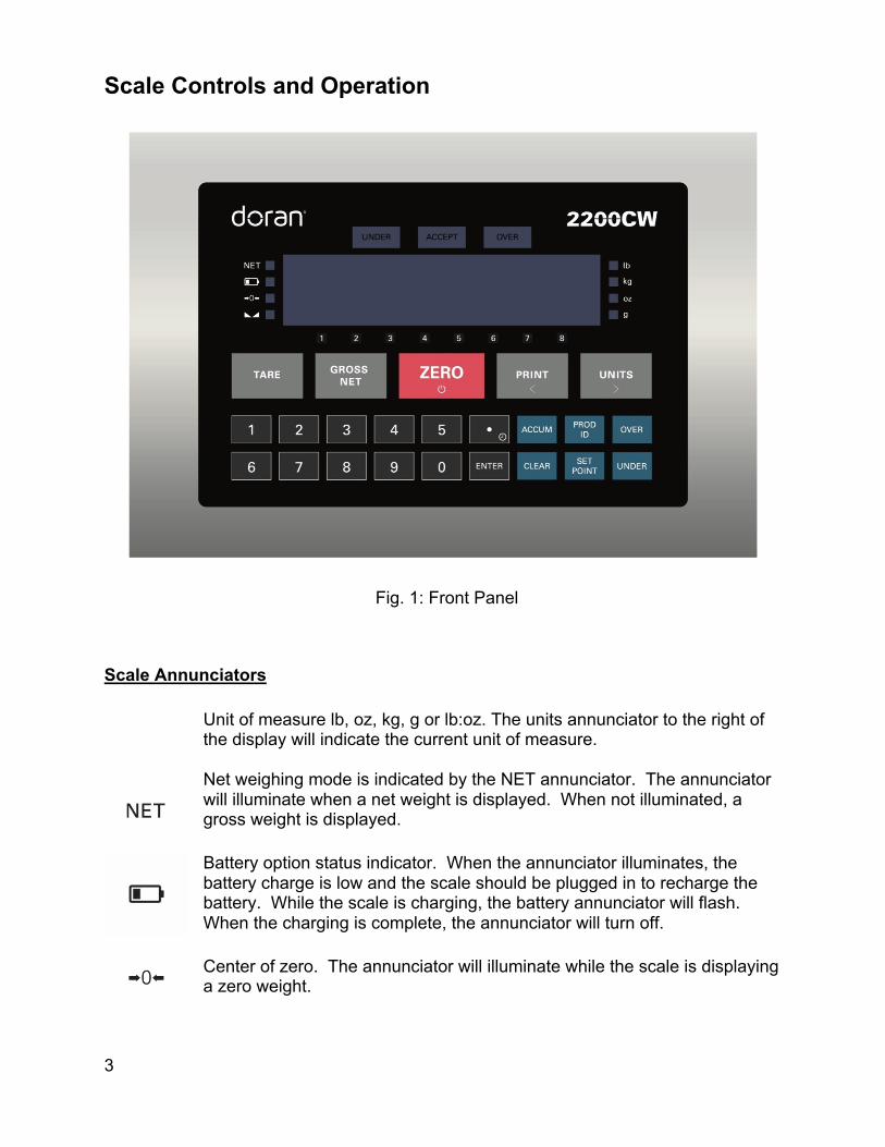
Fig. 1: Front Panel
Scale Annunciators Unit of measure lb, oz, kg, g or lb:oz. The units annunciator to the right of
the display will indicate the current unit of measure.
Net weighing mode is indicated by the NET annunciator. The annunciator will illuminate when a net weight is displayed. When not illuminated, a gross weight is displayed.
Battery option status indicator. When the annunciator illuminates, the battery charge is low and the scale should be plugged in to recharge the battery. While the scale is charging, the battery annunciator will flash. When the charging is complete, the annunciator will turn off.
Center of zero. The annunciator will illuminate while the scale is displaying a zero weight.
4
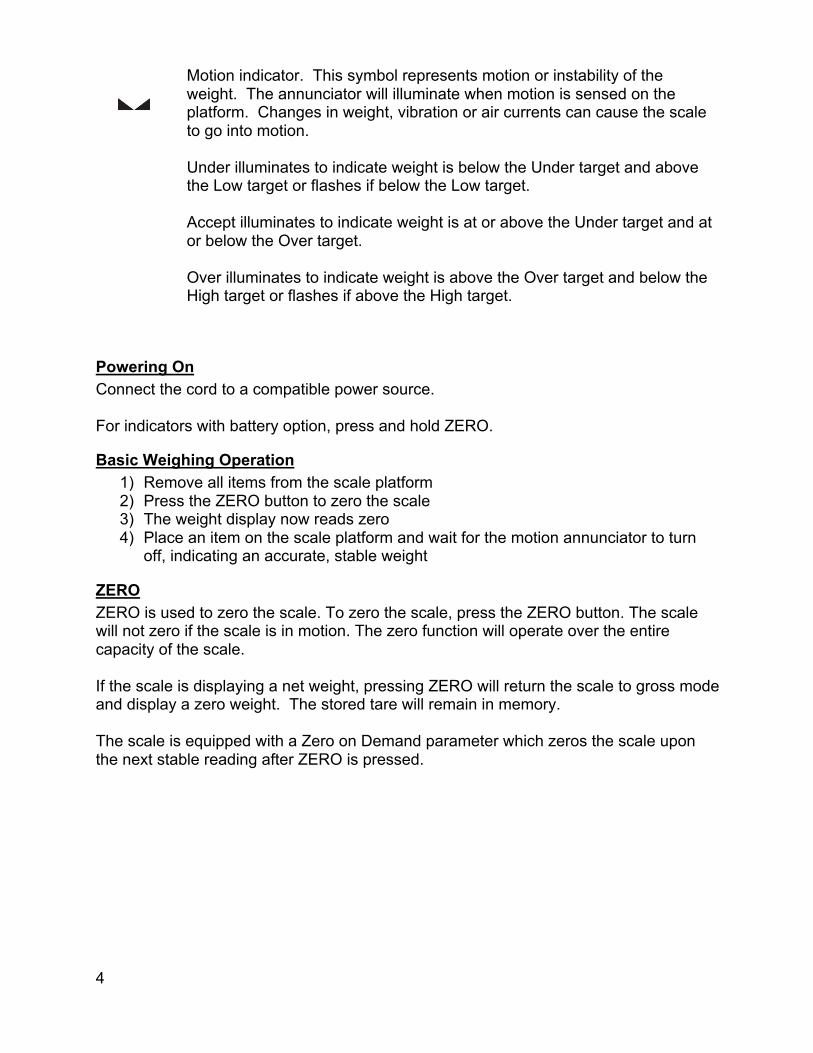
Motion indicator. This symbol represents motion or instability of the weight. The annunciator will illuminate when motion is sensed on the platform. Changes in weight, vibration or air currents can cause the scale to go into motion.
Under illuminates to indicate weight is below the Under target and above the Low target or flashes if below the Low target.
Accept illuminates to indicate weight is at or above the Under target and at or below the Over target.
Over illuminates to indicate weight is above the Over target and below the High target or flashes if above the High target.
Powering On Connect the cord to a compatible power source. For indicators with battery option, press and hold ZERO.
Basic Weighing Operation 1) Remove all items from the scale platform 2) Press the ZERO button to zero the scale 3) The weight display now reads zero 4) Place an item on the scale platform and wait for the motion annunciator to turn
off, indicating an accurate, stable weight
ZERO ZERO is used to zero the scale. To zero the scale, press the ZERO button. The scale will not zero if the scale is in motion. The zero function will operate over the entire capacity of the scale. If the scale is displaying a net weight, pressing ZERO will return the scale to gross mode and display a zero weight. The stored tare will remain in memory. The scale is equipped with a Zero on Demand parameter which zeros the scale upon the next stable reading after ZERO is pressed.

5
TARE Place the item you wish to tare on the scale platform and press TARE. The scale will display a net weight and the NET annunciator will illuminate. Tare weights will remain in memory even if the indicator is turned off.
Keyboard TARE entry Enter a weight and press TARE to save or press CLEAR to cancel tare entry. The scale will display a net weight and the NET annunciator will illuminate.
Display TARE value To display the current tare value, press and hold TARE for three seconds. The display will briefly read tare then flash the tare weight in the currently selected units. To exit press CLEAR.
Clear TARE value Enter 0 and press TARE. This will remove the tare weight from memory.
GROSS NET selection Press the GROSS NET button to switch between the gross and net weighing mode. Switching to the net mode is possible only when a tare is entered. Net mode is indicated when the NET annunciator is illuminated.
UNITS UNITS selects the unit of measure. Press UNITS to change the current unit. The units annunciator to the right of the display will indicate the current unit or measure: lb,oz, kg, g or lb:oz. Each unit can be enabled or disabled in the scale parameter setup. Lb:oz is disabled by default. Lb:oz is not available for tolerance, checkweigh, or setpoint values and cannot be transmitted as data.
PRINT PRINT transmits data to a printer or other external devices. When the data is transmitted, the leftmost display digit will momentarily display an "r" to confirm data transmission. There are many parameters that customize the control of manual and automatic transmission of data. Data can be transmitted via standard RS232, Ethernet, WiFi, Bluetooth or USB options. Contact Doran Tech Support at [email protected] for support.
OVER OVER allows entry of the upper checkweighing limits. It is also used to increment a checkweighing value that is being modified.

6
UNDER UNDER allows entry of the lower checkweighing limits. It is also used to decrement a checkweighing value that is being modified. Password Protected Values To activate password protection, the PASS parameter must be configured with a numeric password. Once configured, password protection will be activated upon power up. If password protection is activated, the display will show PASS when SETPOINT, TARE, UNDER, or OVER values are displayed. Password protection also inhibits deletion or creation of new product IDs. Enter the password and press ENTER, the display will then show PASS and then OFF. Protection is now disabled and values can be accessed and changed. To reactivate password protection, press and hold ENTER for 2 seconds. The display will show PASSon.

7
Battery Operation The indicator can be optionally configured with a self-contained Rechargeable Sealed Lead-Acid battery and charging circuit, both internal. The scale is designed to run continuously for up to 60 hours with a single 350 ohm load cell. To maximize battery life, leave the auto-off timer enabled which will automatically power down the scale after a period of non-use.
Power Off 1) Manual - Press and hold the ZERO push button until the display turns off. The scale
will not turn off if plugged in but will instead display “relpb”. 2) Automatic - At the end of the Unit On Timer (2.4 tdy) scale parameter setting. The
scale will not turn off if plugged in.
Low Battery Indication
The battery annunciator indicates that the battery is in need of recharging. Once it turns on, there will be approximately one hour of battery life remaining before the scale turns off. Multiple load cells, USB, Bluetooth, Ethernet, 4-20mA and WiFi communications will reduce battery life.
Recharging Battery To charge the battery, plug the line cord into a wall outlet. While the scale is charging, the battery annunciator will flash. The charging circuit will fully charge the battery in approximately eight hours. When the charging is complete, the annunciator will turn off. The scale can be used while recharging the battery. Leaving the scale plugged in will ensure a fully charged battery and will not affect the life of the battery. The battery is able to support up to 1000 recharges. This is an estimate as many factors can affect battery life, including severe temperature changes and charging before the scale displays low battery.
8
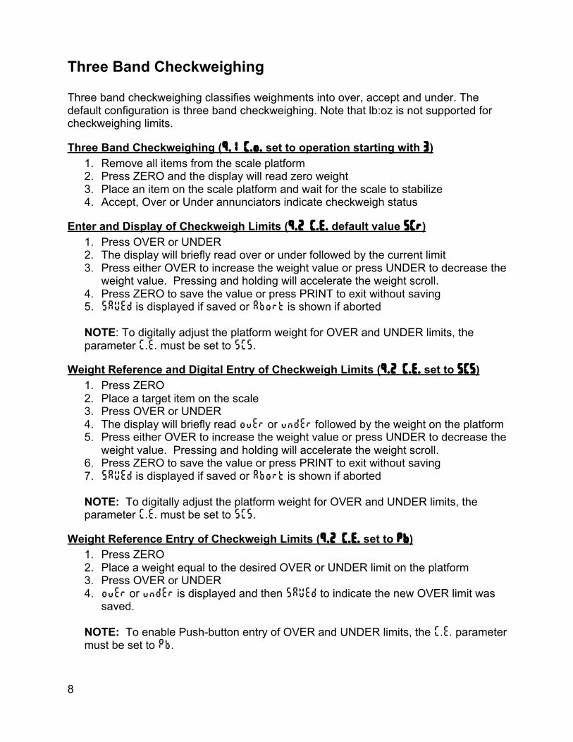
Three Band Checkweighing Three band checkweighing classifies weighments into over, accept and under. The default configuration is three band checkweighing. Note that lb:oz is not supported for checkweighing limits.
Three Band Checkweighing (9.1 C.o. set to operation starting with 3) 1. Remove all items from the scale platform 2. Press ZERO and the display will read zero weight 3. Place an item on the scale platform and wait for the scale to stabilize 4. Accept, Over or Under annunciators indicate checkweigh status
Enter and Display of Checkweigh Limits (9.2 C.E. default value SCr) 1. Press OVER or UNDER 2. The display will briefly read over or under followed by the current limit 3. Press either OVER to increase the weight value or press UNDER to decrease the
weight value. Pressing and holding will accelerate the weight scroll. 4. Press ZERO to save the value or press PRINT to exit without saving 5. saVed is displayed if saved or abort is shown if aborted
NOTE: To digitally adjust the platform weight for OVER and UNDER limits, the parameter C.E. must be set to SCS.
Weight Reference and Digital Entry of Checkweigh Limits (9.2 C.E. set to SCS) 1. Press ZERO 2. Place a target item on the scale 3. Press OVER or UNDER 4. The display will briefly read over or under followed by the weight on the platform 5. Press either OVER to increase the weight value or press UNDER to decrease the
weight value. Pressing and holding will accelerate the weight scroll. 6. Press ZERO to save the value or press PRINT to exit without saving 7. saVed is displayed if saved or abort is shown if aborted
NOTE: To digitally adjust the platform weight for OVER and UNDER limits, the parameter C.E. must be set to SCS.
Weight Reference Entry of Checkweigh Limits (9.2 C.E. set to Pb) 1. Press ZERO 2. Place a weight equal to the desired OVER or UNDER limit on the platform 3. Press OVER or UNDER 4. over or under is displayed and then saVed to indicate the new OVER limit was
saved.
NOTE: To enable Push-button entry of OVER and UNDER limits, the C.E. parameter must be set to pb.

9
Five Band Checkweighing Five band checkweighing classifies weighments into high, over, accept, under and low. Note that lb:oz is not supported for checkweighing limits.
Five Band Checkweighing (9.1 C.o. set to operation starting with S) 1. Press ZERO 2. Place an item on the scale 3. Checkweigh status is indicated as follows
a. Flashing OVER = HIGH b. Solid OVER = OVER c. Solid ACCEPT = ACCEPT d. Solid UNDER = UNDER e. Flashing UNDER = LOW
Enter and Display of High and Low Limits (9.2 C.E. default value SCr) 1. Press and hold the OVER or UNDER until the display reads High or louu
respectively 2. The current weight value of the saved limit is displayed and checkweigh status
annunciators will flash 3. Press either OVER to increase the weight value or press UNDER to decrease the
weight value. Pressing and holding will accelerate the weight scroll. 4. Press ZERO to save the value or press PRINT to exit without saving 5. saVed is displayed if saved or abort is shown if aborted
NOTE: To digitally adjust the platform weight for OVER and UNDER limits, the parameter C.E. must be set to SCr.
Weight Reference and Digital Entry of High and Low Limits (9.2 C.E. set to SCS)
1. Press ZERO 2. Place an item of the desired weight on the scale platform 3. Press and hold the OVER or UNDER until the display reads High or louu
respectively 4. The current weight value of the saved limit is displayed and checkweigh status
annunciators will flash 5. Press either OVER to increase the weight value or press UNDER to decrease the
weight value. Pressing and holding will accelerate the weight scroll. 6. Press ZERO to save the value or press PRINT to exit without saving 7. saVed is displayed if saved or abort is shown if aborted
NOTE: To digitally adjust the platform weight for OVER and UNDER limits, the parameter C.E. must be set to SCS.

10
Weight Reference Entry of High and Low Limits (9.2 C.E. set to Pb) 1. Press ZERO 2. Place an item of the desired weight on the scale platform 3. Press and hold the OVER or UNDER until the display reads High or louu
respectively 4. The display will briefly read over or under followed by the weight on the platform
and checkweigh status annunciators will flash 5. Press either OVER to increase the weight value or press UNDER to decrease the
weight value. Pressing and holding will accelerate the weight scroll. 6. Press ZERO to save the value or press PRINT to exit without saving 7. saVed is displayed if saved or abort is shown if aborted
NOTE: To enable Push-button entry of OVER and UNDER limits, the C.E. parameter must be set to pb.
Zero Band Checkweighing Basic checkweighing - simply set the desired weight on the platform, press zero and checkweigh based upon the standard tolerances in the O.U. parameter (9.3 O.U.).
Zero Band Checkweighing (9.1 C.o. set to operation starting with 0) 1. Remove all items from the scale platform 2. Place the target weight on the scale platform 3. Press ZERO and the display will read zero weight 4. Remove the target weight 5. Place an item on the scale platform and wait for the scale to stabilize 6. A zero weight will indicate the item is exactly the target weight. Any weight above
or below zero indicates the amount of weight away from the target weight. 7. Accept, Over or Under will be displayed

11
Product ID 800 product IDs are available. Deploying a large library of IDs with multiple scales can be easy to manage with Doran’s QC Weigh and CheckWay data management programs. Product IDs save information that includes:
• Checkweigh limits • Unit of measure • Accumulator and counter values • Tare • Two 40 alphanumeric character fields • Number of samples and alarm timer for QC Weigh • Motion Aperture (1.6 nn.A.) • Threshold (2.5 tHs) • Checkweigh operation (9.1 C.o.) • Checkweigh limit entry (9.2 C.E.) • Output configuration (9.7 ouT)
Recall PRODUCT ID from Memory When powered on, no product ID will be loaded. This is indicated when pressing PROD ID and the display reads OFF. Once a product ID is loaded, the unit of measure is locked in the unit of the product ID. To select a stored product, press PROD ID, enter the ID number and press ENTER. The display will read SaVed to indicate the fields associated with that Product ID number are active. After selecting a product, the scale will measure and display in the units saved for that product. The UNITS button will then be disabled. Selecting product ‘OFF’ will re-enable the UNITS button. Another method to select a product is to press PROD ID, then use the UNITS or PRINT buttons to scroll through the available products. Press ENTER to select the displayed product. The display will read SaVed to indicate the fields associated with that Product ID number are active.
Barcode Scan Recall PRODUCT ID from Memory Press PROD ID to enter the Product ID recall mode. The display will show Id, followed by the current Product ID number. Using Doran’s optional barcode scanner, scan the desired barcode. The display will confirm by showing the barcode value. To exit the ID edit mode, press PROD ID.
Display Current PRODUCT ID Press PROD ID, the display will show Id followed by the currently active product. Press ENTER to leave this mode.
Create New PRODUCT ID Select the desired unit that will be used to checkweigh the new product. Enter a product ID up to 6 digits not currently in memory and press PROD ID. The display will

12
momentarily show NEUU then Id. Then return to weighing mode. All fields associated with the new Product ID number will be blank. To enter and save values for all fields associated with the current Product ID, enter values for each field. When changing products, the display will read SaVed to indicate the all fields associated with the new Product ID number are saved and will be recalled when that product is used again.
Delete PRODUCT ID from Memory Enter the product ID to be deleted and press PROD ID. The display will show pRdId, followed by the product ID number. Press and hold the CLEAR button for more than 2 seconds. The display will show ClrID and then done. The product ID will be set to off until another product ID is selected.
User ID User ID login With the display showing LogIn, enter in through the keypad up to 20 digits for a user ID number. The User ID entered is compared with a list of up to 200 User IDs stored in the scale’s memory). If a User ID entered does not match any of the stored IDs, the display will show Error, no, USEr message.
Barcode Entry of User ID Values Press PROD ID to enter the Product ID entry mode. Press Enter to advance to the User entry mode. The display will show USEr followed by 0. The scale has cleared the current User ID stored in memory. Using Doran’s optional barcode scanner, scan the desired barcode. The display will read ------ to represent the barcode value. If scanned value matches any of the User IDs stored in memory, the display will show SAVEd and exit entry mode. If a User ID does not match, the display will show Error, no, USEr message.
User ID Logout Press and hold the CLEAR button for more than 2 seconds. The display will show ClrUSEr. Display will show LogIn to indicate scale is disabled and requires a user id to login.

13
Product Fields The 2200CW has eight 40-character alphanumeric fields that can be entered and transmitted as desired using custom data strings. In addition, there is a ninth product field for serialization which increments from the five digit number entered. This is useful for custom data labels and data collection.
Display Product Fields To access Product Fields, press and hold PROD ID on the front panel for 3 seconds. The display will show “PF 1” for a second, then display the first 6 characters of the product field if they are numeric. The nine fields can be cycled through by pressing ENTER. Press PROD ID to exit from the Product Field mode.
Product Field Entry To access Product Fields, press and hold PROD ID on the front panel for 3 seconds. The scale display will change from the current platform weight to show which Product Field is ready for entry. For the first field, the display will show “PF 1” for a second, then display the current entry of this field. Product Fields can be entered by barcode, by external communications, or by the keypad on the front panel. When the indicator receives a barcode scanner transmission completed by a carriage return it will accept the scanned field automatically when the filed number is active. If the scanned item is alphanumeric only, press enter to accept the scanned field. A keypad entry followed by pressing ENTER, will store the entered value as that Product Field. Once entered, the scale will then display the next Product Field, in this case “PF 2”. The scale will cycle through the 9 Product Fields unless the user presses PROD ID again, which will exit from the Product Field mode.

14
QC Weigh Operation The 2200CW is capable of automatic checkweigh operation. Through use of our external data management program, ionSuite, users can: input custom products, input unique users, and run reports on the data collected. See the Product ID and User ID sections of this manual for more information of what can be input. QC Weigh requires either the Ethernet or WiFi options to function.
QC Weigh Mode When adding the scale to ionSuite, it tests the connection to the scale and changes the operation to QC Weigh Mode. If needed, the configuration can be changed manually as well. To do so, enter the scale’s Calibration and Parameter Setup Mode, then change parameter 1.12, Operating Mode, to “0.CU”, or QC Weigh. This process is detailed in the Scale Parameter Setup section.
Entering a User ID When in QC Weigh mode, the scale will display “lOgIn”. Users can be added by selecting any scale on the QC Weigh network, selecting the Scale Login Tab and adding users. Once created, the users must be saved to all scales. After putting the scale into QC Weigh Mode, the scale will read “lOgIn”. The scaler can use one of two methods to input their User ID:
The User ID can be scanned off a barcode. Scanning a valid User ID will automatically advance to the next screen.
The User ID can be manually input using the keypad, then press ENTER to advance to the next screen.
Entering a Product ID Ensure that Product IDs are stored on the indicator before attempting to enter a Product ID. This process is done in ionSuite. Product IDs can be up to 20 alphanumeric characters in length. The last 6 characters are displayed on the LED screen. To recall alphanumeric or Product IDs longer than 6 characters, a barcode scanner is suggested.
15
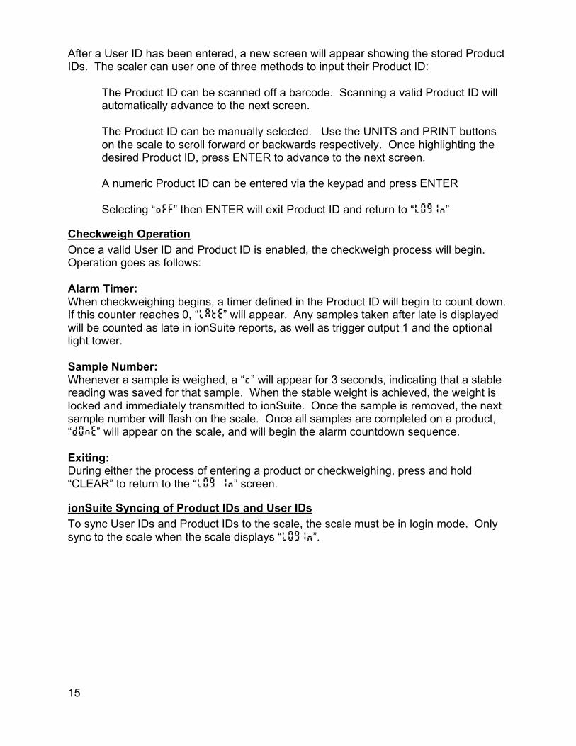
After a User ID has been entered, a new screen will appear showing the stored Product IDs. The scaler can user one of three methods to input their Product ID:
The Product ID can be scanned off a barcode. Scanning a valid Product ID will automatically advance to the next screen.
The Product ID can be manually selected. Use the UNITS and PRINT buttons on the scale to scroll forward or backwards respectively. Once highlighting the desired Product ID, press ENTER to advance to the next screen. A numeric Product ID can be entered via the keypad and press ENTER Selecting “oFF” then ENTER will exit Product ID and return to “lOgIn”
Checkweigh Operation Once a valid User ID and Product ID is enabled, the checkweigh process will begin. Operation goes as follows: Alarm Timer: When checkweighing begins, a timer defined in the Product ID will begin to count down. If this counter reaches 0, “late” will appear. Any samples taken after late is displayed will be counted as late in ionSuite reports, as well as trigger output 1 and the optional light tower. Sample Number: Whenever a sample is weighed, a “c” will appear for 3 seconds, indicating that a stable reading was saved for that sample. When the stable weight is achieved, the weight is locked and immediately transmitted to ionSuite. Once the sample is removed, the next sample number will flash on the scale. Once all samples are completed on a product, “DONE” will appear on the scale, and will begin the alarm countdown sequence. Exiting: During either the process of entering a product or checkweighing, press and hold “CLEAR” to return to the “lOg In” screen.
ionSuite Syncing of Product IDs and User IDs To sync User IDs and Product IDs to the scale, the scale must be in login mode. Only sync to the scale when the scale displays “lOgIn”.

16
Time and Date Setting Time and Date To change the date:
1. Press and hold decimal point / clock button until date is displayed 2. The display flashes the current the date 3. The digits being edited flashes on the display 4. Enter the date with leading zeros in the format MM.DD.YY 5. Press UNITS to advance to the next digit 6. Press UNITS until the display reads saved to confirm the date changes are
saved 7. Press ENTER to return to the normal weighing mode.
To change the time:
1. Press and hold decimal point / clock button until date is displayed 2. Press the decimal point button 3. The display reads tinne when the time in 24hour format is displayed 4. The digit that being edited flashes on the display 5. Enter the time with leading zeros in the format HH.MM.SS 6. Press UNITS to advance to the next digit 7. Press UNITS until the display reads saved to confirm the time changes are saved 8. Press ENTER to return to the normal weighing mode.

17
Accumulator and Counter Accumulator and Counter Operation When a manual or automatic print function is executed, the accumulator has the currently displayed weight added to its’ current value and the counter is incremented. To accumulate automatically, select an auto print function in the parameter setup menu. To accumulate manually, allow the scale to become stable and press PRINT. The maximum value that can be shown for the accumulator and counter is 999,999. When the maximum value is reached, the accumulator and counter will rollover to a zero value. If displayed units are changed, the accumulator is cleared. This feature can only be used in a non Legal For Trade application.
Display Accumulator and Counter Values Press the ACCUM button to enter the accumulator and counter recall mode. The display will show Accunn followed by the accumulated weight in the units currently selected in the weigh mode. Then Countr will be displayed followed by the counter value. Press ACCUM to exit the accumulator and counter recall mode without changing their values.
Clear Accumulator and Counter Press the ACCUM button to enter the accumulator and counter recall mode. The display will show Accunn followed by the accumulated weight in the units currently selected in the weigh mode. Then Countr will be displayed followed by the counter value. Press CLEAR to clear the accumulator and counter values. The display will show ClrAc and exit from the recall mode. Changing the current display units will clear both the accumulator and counter values.
Accumulator and Counter Data String Output to Printer or Data Collection Press ACCUM to enter the accumulator recall mode. Press PRINT to transmit the LB4 custom data string that contains the accumulator and counter values by default. Both the accumulator and counter values are cleared after transmission.
18
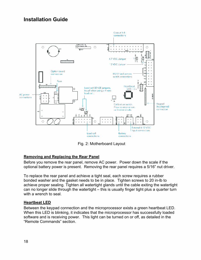
Installation Guide
Fig. 2: Motherboard Layout
Removing and Replacing the Rear Panel Before you remove the rear panel, remove AC power. Power down the scale if the optional battery power is present. Removing the rear panel requires a 5/16” nut driver. To replace the rear panel and achieve a tight seal, each screw requires a rubber bonded washer and the gasket needs to be in place. Tighten screws to 20 in-lb to achieve proper sealing. Tighten all watertight glands until the cable exiting the watertight can no longer slide through the watertight – this is usually finger tight plus a quarter turn with a wrench to seal.
Heartbeat LED Between the keypad connection and the microprocessor exists a green heartbeat LED. When this LED is blinking, it indicates that the microprocessor has successfully loaded software and is receiving power. This light can be turned on or off, as detailed in the “Remote Commands” section.
19
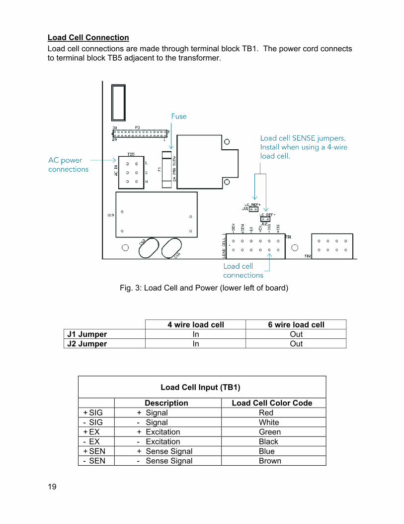
Load Cell Connection Load cell connections are made through terminal block TB1. The power cord connects to terminal block TB5 adjacent to the transformer.
Fig. 3: Load Cell and Power (lower left of board)
4 wire load cell 6 wire load cell J1 Jumper In Out J2 Jumper In Out
Load Cell Input (TB1)
Description Load Cell Color Code + SIG + Signal Red - SIG - Signal White + EX + Excitation Green - EX - Excitation Black + SEN + Sense Signal Blue - SEN - Sense Signal Brown
20
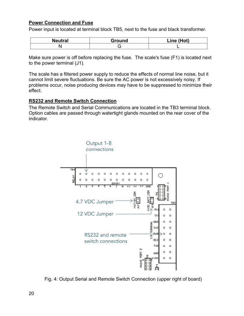
Power Connection and Fuse Power input is located at terminal block TB5, next to the fuse and black transformer.
Neutral Ground Line (Hot) N G L
Make sure power is off before replacing the fuse. The scale's fuse (F1) is located next to the power terminal (J1). The scale has a filtered power supply to reduce the effects of normal line noise, but it cannot limit severe fluctuations. Be sure the AC power is not excessively noisy. If problems occur, noise producing devices may have to be suppressed to minimize their effect.
RS232 and Remote Switch Connection The Remote Switch and Serial Communications are located in the TB3 terminal block. Option cables are passed through watertight glands mounted on the rear cover of the indicator.
Fig. 4: Output Serial and Remote Switch Connection (upper right of board)

21
22
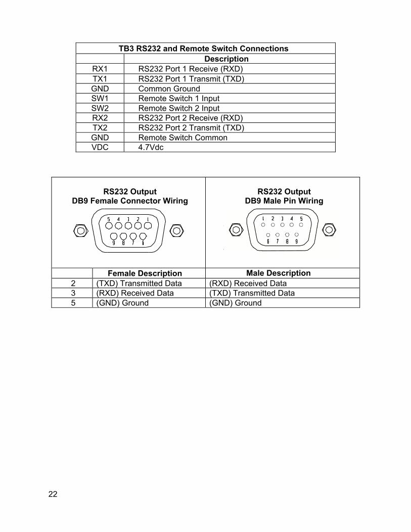
TB3 RS232 and Remote Switch Connections
Description RX1 RS232 Port 1 Receive (RXD) TX1 RS232 Port 1 Transmit (TXD) GND Common Ground SW1 Remote Switch 1 Input SW2 Remote Switch 2 Input RX2 RS232 Port 2 Receive (RXD) TX2 RS232 Port 2 Transmit (TXD) GND Remote Switch Common VDC 4.7Vdc
RS232 Output
DB9 Female Connector Wiring
RS232 Output
DB9 Male Pin Wiring
Female Description Male Description 2 (TXD) Transmitted Data (RXD) Received Data 3 (RXD) Received Data (TXD) Transmitted Data 5 (GND) Ground (GND) Ground
23
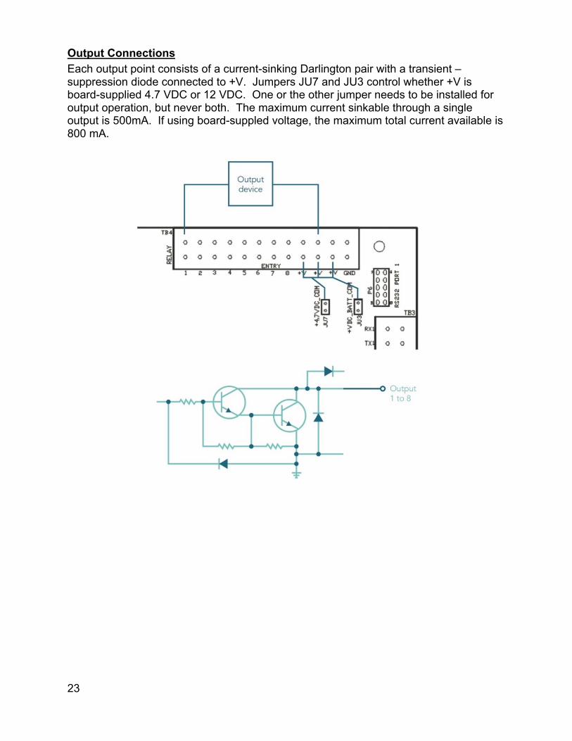
Output Connections Each output point consists of a current-sinking Darlington pair with a transient –suppression diode connected to +V. Jumpers JU7 and JU3 control whether +V is board-supplied 4.7 VDC or 12 VDC. One or the other jumper needs to be installed for output operation, but never both. The maximum current sinkable through a single output is 500mA. If using board-suppled voltage, the maximum total current available is 800 mA.

24
Calibration Guide Entering Calibration and Parameter Setup Mode Front Panel Access
1. Press and hold ZERO and UNITS simultaneously until the audit counters are displayed.
2. Ent Cd is displayed 3. Press ZERO 5 times, so that 5 is displayed, 4. Press UNITS
Internal Calibration Button The calibration push button is located near the center of the board and labeled CAL. Press this button to enter calibration and setup.
Exit Calibration and Parameter Setup Mode Front Panel Access
1. Press UNITS until the display reads 99. don. 2. Press the ZERO button 3. The display reads donEn 4. Press the ZERO button 5. The display reads donEy 6. Press UNITS to return to the run mode 7. Display reads SAVEd to confirm changes are saved to memory
Internal Calibration Button The calibration push button is located near the center of the board and labeled CAL. Press this button to exit calibration and save settings.
Set Scale Capacity The Capacity selection is displayed after entering the Calibration and Setup mode.
1. 1 CAL is displayed 2. Press ZERO 3. The display will alternate between CAP Aj and the currently selected capacity 4. Press ZERO to change the capacity 5. The units annunciator will flash indicating the unit of measure for the capacity.
Press ZERO to change the unit of measure if required. 6. Press PRINT 7. The right most digit will flash. Press ZERO to change this number from 0 to 9. 8. Press PRINT to move to the next digit to the left. 9. Repeat until all digits have been set to the desired scale capacity. 10. Once the digits have been set, the display will return to alternately displaying CAP
Aj and the new capacity value.

25
Set Scale Count By After the capacity has been entered, count by(resolution) will automatically be set for a legal for trade 5000 division level.
1. After calibration, press UNITS. 2. The display will alternate between Cntby and the current count by 3. Press ZERO to select the desired count by 4. To exit and save changes, press UNITS until donEn is displayed. 5. Press ZERO 6. donEy will be displayed 7. Press UNITS to return to the run mode
Calibration After count by has been set, calibration is required
1. Press UNITS until CAL0 appears on the display 2. Remove all weight from the scale platform 3. Press ZERO and wait for the display to count down to 0 4. The display will alternate between CALFS and the scale capacity 5. Place the calibration weight on the scale platform (2% of capacity to full capacity) 6. If calibrating at scale capacity, press ZERO to begin calibration and move to step
12. If not calibrating at the scale capacity, continue to step 7. 7. Press PRINT 8. The right most digit will flash. Press ZERO to change this number from 0 to 9. 9. Press PRINT to move to the next digit to the left 10. Repeat until all digits have been set to the desired calibration weight 11. Press PRINT and the calibration process will begin and the display will count
down to zero. 12. The display will momentarily display done, followed by saved and return to the
normal weighing mode 13. Verify scale calibration
NOTE: Calibration at 2% of capacity has been provided as a convenience to customers with scales in inaccessible locations. Scales calibrated at 2% will not be as accurate at full capacity compared to scales calibrated at full capacity. It is the responsibility of the installer to ensure that scale accuracy is achieved after any calibration.
Calibration Error Codes Code Solution SPAnE The calibration span is out of range. Press ZERO to clear this error.
Refer to the Scale Calibration Error Troubleshooting section. ernna The scale is sensing an unstable weight. Remove any vibration or air
currents to continue calibration.
26
Scale Calibration Error Troubleshooting The allowable load cell signal input range is 0.30 mV/V to 5.0 mV/V.
1. Calculate scale divisions by dividing the scale capacity by the count by. Example: For a 50 x 0.01 lb scale, divide 50 by 0.01 for a result of 5000d
2. Enter the calibration and parameter setup mode. 3. Press PRINT until the configuration menu 2Cnfg is displayed. 4. Press ZERO to enter the configuration menu. 5. Press UNITS until the scale counts are displayed. 6. Remove all items from the platform and record the zero load scale counts
reading. 7. Place full capacity on the platform and record the scale counts. 8. Subtract the zero load counts from the full load counts to calculate the span. 9. The span number, from step #7, must be higher than the scale divisions found in
step #1.
The maximum span, at full load is 750,000. If the span is higher, the span calibration will not be accepted. If the span counts are too low or too high, check the load cell connections. If the connections are correct, replace the load cell.
27
Scale Parameter Setup Entering Calibration and Parameter Setup Mode Front Panel Access
1. Press and hold ZERO and UNITS simultaneously until the audit counters are displayed.
2. Ent Cd is displayed 3. Press ZERO 5 times, so that 5 is displayed, 4. Press UNITS
Internal Calibration Button The calibration push button is located near the center of the board and labeled CAL. Press this button to enter calibration and setup.
Exit Calibration and Parameter Setup Mode Front Panel Access
1. Press UNITS until the display reads 99. don. 2. Press the ZERO button 3. The display reads donEn 4. Press the ZERO button 5. The display reads donEy 6. Press UNITS to return to the run mode 7. Display reads SAVEd to confirm changes are saved to memory
Internal Calibration Button The calibration push button is located near the center of the board and labeled CAL. Press this button to exit calibration and save settings.
Navigating Parameter Menu with Keypad To navigate to a specific parameter, first enter calibration and parameter setup mode, as described above. Then, enter the parameter group number, a decimal point, and the element number, followed by the ENTER button. These values are located to the left of each parameter outlined later.
Navigating Parameter Menu with ZERO, UNITS, and PRINT Press UNITS and PRINT navigate to the desired top level parameter group. Enter the group by pressing ZERO. Once within a group, press UNITS to advance, PRINT to back up and ZERO to change the currently displayed parameter setting.

28
Parameter Groups The scale parameters are divided up into eight parameter groups. Each group contains related parameters. Below is a brief list describing each parameter group.
1 CAL Capacity and Calibration 2 CnFg General Settings 3 SEr1 Serial port #1 4 SEr2 Serial port #2 5 Eth Ethernet 6 uufi Wireless Ethernet 7 bt Bluetooth 8 USb USB 9 oPER Checkweigh Operation 99 don Exit Setup
Legal for Trade Restrictions When the Legal for Trade mode is enabled, it automatically disables some menus and parameter options. This is done to comply with NTEP and CWM requirements. The menus and parameter sections are shown on the following pages. Menus and parameters not available when in the Legal for Trade mode are marked by an asterisk.
Audit Counters When entering calibration mode, the Parameter audit counter and the Calibration audit counter will momentarily be displayed. The Parameter audit counter increments when legal for trade values are changed. The Calibration audit counter increments when the scale is calibrated.
Software Part Number and Revision Level During the front panel access procedure, the scale will display the software number and revision. The software number is Su 191 followed by the software revision level rEv. Please have the software number 191 and the revision level available when contacting our technical support department.

29
Capacity and Calibration - 1 CAL
1.1 CAP Aj Capacity Adjustment
1 - 999000
1 lb / kg to 999,000 lb / kg Refer to calibration guide for more detail
1.2 CntBy Count By Setup Menu Also known as resolution or division
0.00002
5000
Selection limited by scale capacity Capacity/resolution (scale divisions) maximum value is 50,000d and minimum value is 200d
1.3 CAL Calibration Mode
0
Calibration Zero Press ZERO to perform calibration of the scale zero Successful calibration is indicated by "CAL FS"
XXXXXX
Only appears after a successful zero calibration Enter calibration weight through keypad and decimal point if required.
1.4 Avg Display Filter Setting Determines speed of digital filtering
1 Fastest display updates, most sensitive setting 2 Default Setting 4 8 16 32 64 Slowest display updates, least sensitive setting

30
1.5 A2t* Automatic Zero Tracking Range Weight within the specified number of divisions are automatically zeroed
oFF Zero tracking is off, no automatic zeroing 0.5 Zero tracking to within 0.5 division 1* Zero tracking to within 1 division 3* Zero tracking to within 3 divisions 5* Zero tracking to within 5 divisions 10* Zero tracking to within 10 divisions 20* Zero tracking to within 20 divisions
1.6 nn.A.* Motion aperture* Determines the number of divisions that consecutive readings must change before the scale is considered to be in motion
0.5* 0.5 divisions 1 1 division 2* 2 divisions 3* 3 divisions 5* 5 divisions 10* 10 divisions
1.7 nn.d* Motion Delay* Length of a motion indication display.
1 - 9
Length of a motion indication display, in 100ms intervals. Default is 3. (Locked to 3 in Legal for Trade mode)
1.8 SU0* Start Up Zero Controls the zero point when the scale is turned on
on Zeros on the first stable reading on power up CL0 Loads the calibration zero point PB0* Loads the last pushbutton zero
1.9 tar Tare Input
Pbn Tare Pushbutton as well as keypad entry Pb Tare Pushbutton only n Keypad only off No tare entry
*Parameters not available in Legal for Trade mode

31

32
1.10 2od Zero on Demand Enables or disable zero latching
on If ZERO is pressed, it is saved until the scale becomes stable.
oFF If the scale is in motion, the zero request is discarded.
1.11 Pod Print on Demand Enables or disables print latching
on If PRINT is pressed, the print request is saved until the scale becomes stable.
oFF If the scale is in motion, the print request is discarded.
nnt Print when requested, whether the scale is in motion or not
1.12 oP Operating Mode
Std Standard operation
44 NTEP legal-for-trade. Restricts parameters to keep them within NTEP limits.
445 CWM legal-for-trade. Restricts parameters to keep them within CWM limits.
O.CU
QC Weigh mode. In this mode, PROD ID, GROSS/NET, ACCUM, OVER, UNDER, SETPOINT, and TARE buttons are disabled.
PrS
Production Sentry mode. In this mode, GROSS/NET, ACCUM, OVER, UNDER, SETPOINT, and TARE buttons are disabled.
1.14 donE Exit Calibration and Setup
y Saves and exits setup when PRINT or UNITS is pressed.
n Remains in setup

33
General Settings - 2 Cnfg
2.1 CSL Unit Enable and Disable Determines which unit selections will be active
no Do not enter Convert selection menu yes Enter Convert selection menu
lb pounds menu on lb is active off lb is non active hg kilograms menu on kg is active off kg is non active o2 ounces menu on oz is active off oz is non active gr grams menu on g is active off g is non active Lo pound:ounce menu on lb:oz is active off lb:oz is non active
NOTE: oz units are disabled for capacities greater than 60,000 lb grams units are disabled for capacities greater than 2000 lb lb:oz are only available for capacities between 10 and 1000 lb
2.2 UnitS Start Up Units Select Mode Configures selection of startup units
The unit annunciator, to the right of the display, indicates the active unit on power up. Press ZERO to change the selection.

34
2.3 P.b. Push Button Enable and Disable Determines which buttons are active or inactive
no Do not enter push button selection menu yes Enter push button selection menu
Pr PRINT button
on pb is active off pb is non active
Ut UNITS button
on pb is active off pb is non active
2r ZERO button
on pb is active off pb is non active
r1, r2 REMOTE SWITCH 1 and 2 function
off Remote pb is non active 2r ZERO Pr PRINT Ut UNITS Ac ACCUM Tr TARE
Gn GROSS NET oU Over and Under buttons
on pb is active
off pb is not active gn GROSS NET button
on pb is active
off pb is not active Ac ACCUM button
on pb is active
off pb is not active (disables accumulator function)
SP SETPOINT button
on pb is active
off pb is non active tr TARE button
on pb is active
off pb is non active id PRODUCT ID button
on pb is active
off pb is non active

35
2.4 tdy Automatic off Timer Only visible when batt parameter is set to y
on Unit will remain on, On timer is off 0.5 30 second On timer 1 1 minute On timer 1.5 1.5 minute On timer 2 2 minute On timer 3 3 minute On timer 5 5 minute On timer 10 10 minute On timer 30 30 minute On timer 1hr 1 hour On timer 2hr 2 hour On timer 4hr 4 hour On timer 8hr 8 hour On timer
2.5 tHs
Threshold Level Entry Controls some printing features, setpoints, and outputs
0.1 - 9.9
+0.1% to +9.9% of capacity Default setting is 1%
2.6 dEFt Default Used to set parameters to factory default values
n Do not default Y Set parameters to default values
2.7 Counts Raw counts from the AD converter Used for troubleshooting during calibration
xxxxxx -99999 to 999999
2.8 brt Controls the brightness of all LEDs
1-15
Can be set to a value of 1 to 15 with 15 being the brightest. Default value is 9. Note: Decreasing brightness conserves battery life.
2.9 batt Enable or disable battery operation
n Battery option not installed y Battery option installed

36
2.10 PASS Enable or disable password
n Password inactive
y
Password active – press UNITS, enter numeric password and press ENTER. The password must be a minimum of 3 digits and no longer than 6 digits.
Serial (RS232) Port 1 - 3 SEr1
3.1 d.o.1 Data Output Mode Port 1
t.o.d. Transmit on demand. Transmit when the PRINT button is pressed.
A.P.1 Auto Print 1. Transmit once only when scale becomes stable.
A.P.2
Auto Print 2. Transmit once only when scale becomes stable. Scale must return to, or below, the threshold range (2.5 tHs).
A.P.3
Auto Print 3. Transmit once when the scale stabilizes within the ACCEPT range. Weight must fall below the threshold value (2.5 tHs) before transmitting again.
A.P.4
Auto Print 4. Transmit first stable weight outside of threshold. Transmission happens when weight returns to threshold range (2.5 tHs).
A.P.5
Auto Print 5. Transmit the last stable weight outside of threshold. Transmission happens when weight returns to threshold range (2.5 tHs).
T1 Transmits every 1 second. T5 Transmits every 5 seconds. T60 Transmits every 60 seconds.
C.P. Continuous Print. Transmit when display is updated. Approximately every 1/10th of a second.
oFF Port disabled Note: only one communication port can have a timed output mode (t1, t5, t60, or CP)
3.2 For.1 Data Output Format Port 1
F0 Basic output format 2d Basic Dual Print Format. Includes Kilogram weight. SSP Basic Output for label printer F9 Model 8000 emulation Lb1 User definable print string with default values Lb2 User definable print string with default values Lb3 User definable print string with default values Lb4 User definable print string

37
bo WinSPC compatibility format
3.3 br.1 Baud Rate Port 1
12 1200 baud 24 2400 baud 48 4800 baud 96 9600 baud 14.4 14,400 baud 19.2 19,200 baud 28.8 28,800 baud 38.4 38,400 baud
Serial (RS232) Port 2 - 4 SEr2
4.1 d.o. 2 Data Output Mode Port 2
t.o.d. Transmit on demand. Transmit when the PRINT button is pressed.
A.P.1 Auto Print 1. Transmit once only when scale becomes stable.
A.P.2
Auto Print 2. Transmit once only when scale becomes stable. Scale must return to, or below, the threshold range (2.5 tHs).
A.P.3
Auto Print 3. Transmit once when the scale stabilizes within the ACCEPT range. Weight must fall below the threshold value (2.5 tHs) before transmitting again.
A.P.4
Auto Print 4. Transmit first stable weight outside of threshold. Transmission happens when weight returns to threshold range (2.5 tHs).
A.P.5
Auto Print 5. Transmit the last stable weight outside of threshold. Transmission happens when weight returns to threshold range (2.5 tHs).
T1 Transmits every 1 second. T5 Transmits every 5 seconds. T60 Transmits every 60 seconds.
C.P. Continuous Print. Transmit when display is updated. Approximately every 1/10th of a second.
oFF Port disabled Note: only one communication port can have a timed output mode (t1, t5, t60, or CP)

38
4.2 For. 2 Data Output Format Port 2
F0 Basic output format 2d Basic Dual Print Format. Includes Kilogram weight. SSP Basic Output for label printer F9 Model 8000 emulation Lb1 User definable print string with default values Lb2 User definable print string with default values Lb3 User definable print string with default values Lb4 User definable print string bo WinSPC compatibility format
4.3 br. 2 Baud Rate Port 2
12 1200 baud 24 2400 baud 48 4800 baud 96 9600 baud 14.4 14,400 baud 19.2 19,200 baud 28.8 28,800 baud 38.4 38,400 baud

39
Wired Ethernet - 5 Eth
5.1 d.o. E Data Output Mode Ethernet
t.o.d. Transmit on demand. Transmit when the PRINT button is pressed.
A.P.1 Auto Print 1. Transmit once only when scale becomes stable.
A.P.2
Auto Print 2. Transmit once only when scale becomes stable. Scale must return to, or below, the threshold range (2.5 tHs).
A.P.3
Auto Print 3. Transmit once when the scale stabilizes within the ACCEPT range. Weight must fall below the threshold value (2.5 tHs) before transmitting again.
A.P.4
Auto Print 4. Transmit first stable weight outside of threshold. Transmission happens when weight returns to threshold range (2.5 tHs).
A.P.5
Auto Print 5. Transmit the last stable weight outside of threshold. Transmission happens when weight returns to threshold range (2.5 tHs).
T1 Transmits every 1 second. T5 Transmits every 5 seconds. T60 Transmits every 60 seconds.
C.P. Continuous Print. Transmit when display is updated. Approximately every 1/10th of a second.
C.P. UdP Continuous Print. Transmit on selected UDP port when display is updated. Approximately every 1/10th of a second.
oFF Port disabled Note: only one communication port can have a timed output mode (t1, t5, t60, or CP)
5.2 For. E Data Output Format Ethernet
F0 Basic output format 2d Basic Dual Print Format. Includes Kilogram weight. SSP Basic Output for Label printer F9 Model 8000 emulation Lb1 User definable print string with default values Lb2 User definable print string with default values Lb3 User definable print string with default values Lb4 User definable print string bo WinSPC compatibility format
5.3 iP.xxxx Static or DHCP IP Address Assignment
iP.dhCp DHCP - address supplied by network server

40
iP.StAt Static - address assigned at indicator
5.4 iP Adr Static IP Address Assignment
Current IP address of the scale. Cannot be changed if the previous parameter is set to DHCP
5.5 Subnet Subnet Mask
Current subnet setting. Cannot be changed if set for DHCP
5.6 6ate IP Gateway
Current IP Gateway. Cannot be changed if set for DHCP
5.7 Port TCP Port Number
xxxxx Indicates the listening TCP port number of the scale
5.8 nnac Ethernet MAC Address
xxxxxx.xxxxxx The unique Ethernet MAC address. Cannot be changed.
5.9 4nnA 4mA point adjustment
0-255 Use this value to adjust the 4mA output, if that option is installed on your scale. Default is 127.
5.10 20nnA 20mA point adjustment
0-255 Use this value to adjust the 20mA output, if that option is installed on your scale. Default is 127.

41
5.11 UDPiP UDP IP Address
Current IP address that the scale will use to send UDP packets.
5.12 U Port UDP Port Number
xxxxx Indicates the transmission UDP port number of the scale.
Wireless Ethernet – 6 uufi
6.1 d.o. UU Data Output Mode wifi
t.o.d. Transmit on demand. Transmit when the PRINT button is pressed.
A.P.1 Auto Print 1. Transmit once only when scale becomes stable.
A.P.2
Auto Print 2. Transmit once only when scale becomes stable. Scale must return to, or below, the threshold range (2.5 tHs).
A.P.3
Auto Print 3. Transmit once when the scale stabilizes within the ACCEPT range. Weight must fall below the threshold value (2.5 tHs) before transmitting again.
A.P.4
Auto Print 4. Transmit first stable weight outside of threshold. Transmission happens when weight returns to threshold range (2.5 tHs).
A.P.5
Auto Print 5. Transmit the last stable weight outside of threshold. Transmission happens when weight returns to threshold range (2.5 tHs).
T1 Transmits every 1 second. T5 Transmits every 5 seconds. T60 Transmits every 60 seconds.
C.P. Continuous Print. Transmit when display is updated. Approximately every 1/10th of a second.
oFF Port disabled Note: only one communication port can have a timed output mode (t1, t5, t60, or CP)

42
6.2 For. UU Data Output Format wifi
F0 Basic output format 2d Basic Dual Print Format. Includes Kilogram weight. SSP Basic Output for label printer F9 Model 8000 emulation Lb1 User definable print string with default values Lb2 User definable print string with default values Lb3 User definable print string with default values Lb4 User definable print string bo WinSPC compatibility format
6.3 iP.xxxx Static or DHCP IP Address Assignment
iP.dhCp DHCP - address supplied by network server iP.StAt Static - address assigned at indicator
6.4 iP Adr Static IP Address Assignment
Current IP address of the scale. Cannot be changed if the previous parameter is set to DHCP.
6.5 Subnet Subnet Mask
Current subnet setting. Cannot be changed if set for DHCP
6.6 6ate IP Gateway
Current IP Gateway. Cannot be changed if set for DHCP
6.7 Port TCP Port Number
xxxxx Indicates the listening TCP port number of the scale.

43
6.8 iDLE Idle Timeout
0 - 65536
Number of seconds during which no data is transmitted or received before the connection is automatically closed. Default is 0 seconds. Setting the timer to 0 prevents disconnecting.
6.9 nnac Ethernet MAC Address
xxxxxx.xxxxxx The unique Ethernet MAC address. Cannot be changed.
6.10 CS Wifi Connection Status
8 - The unit is not connected 88 - The unit is connecting. 888 - The unit is connected There is no entry on this screen. This is a display that reports the wifi connection status.

44
Bluetooth – 7 bt
7.1 d.o. bt Data Output Mode Bluetooth
t.o.d. Transmit on demand. Transmit when the PRINT button is pressed.
A.P.1 Auto Print 1. Transmit once only when scale becomes stable.
A.P.2
Auto Print 2. Transmit once only when scale becomes stable. Scale must return to, or below, the threshold range (2.5 tHs).
A.P.3
Auto Print 3. Transmit once when the scale stabilizes within the ACCEPT range. Weight must fall below the threshold value (2.5 tHs) before transmitting again.
A.P.4
Auto Print 4. Transmit first stable weight outside of threshold. Transmission happens when weight returns to threshold range (2.5 tHs).
A.P.5
Auto Print 5. Transmit the last stable weight outside of threshold. Transmission happens when weight returns to threshold range (2.5 tHs).
T1 Transmits every 1 second. T5 Transmits every 5 seconds. T60 Transmits every 60 seconds.
C.P. Continuous Print. Transmit when display is updated. Approximately every 1/10th of a second.
oFF Port disabled Note: only one communication port can have a timed output mode (t1, t5, t60, or CP)
7.2 For. b Data Output Format Bluetooth
F0 Basic output format 2d Basic Dual Print Format. Includes Kilogram weight. SSP Basic Output for label printers F9 Model 8000 emulation Lb1 User definable print string with default values Lb2 User definable print string with default values Lb3 User definable print string with default values Lb4 User definable print string bo WinSPC compatibility format

45
USB - 8 USb
8.1 d.o. Usb Data Output Mode USB
t.o.d. Transmit on demand. Transmit when the PRINT button is pressed.
A.P.1 Auto Print 1. Transmit once only when scale becomes stable.
A.P.2
Auto Print 2. Transmit once only when scale becomes stable. Scale must return to, or below, the threshold range (2.5 tHs).
A.P.3
Auto Print 3. Transmit once when the scale stabilizes within the ACCEPT range. Weight must fall below the threshold value (2.5 tHs) before transmitting again.
A.P.4
Auto Print 4. Transmit first stable weight outside of threshold. Transmission happens when weight returns to threshold range (2.5 tHs).
A.P.5
Auto Print 5. Transmit the last stable weight outside of threshold. Transmission happens when weight returns to threshold range (2.5 tHs).
T1 Transmits every 1 second. T5 Transmits every 5 seconds. T60 Transmits every 60 seconds.
C.P. Continuous Print. Transmit when display is updated. Approximately every 1/10th of a second.
oFF Port disabled Note: only one communication port can have a timed output mode (t1, t5, t60, or CP)
8.2 For. Usb Data Output Format USB
F0 Basic output format 2d Basic Dual Print Format. Includes Kilogram weight. SSP Basic Output for label printers F9 Model 8000 emulation Lb1 User definable print string with default values Lb2 User definable print string with default values Lb3 User definable print string with default values Lb4 User definable print string bo WinSPC compatibility format

46
Checkweigh and Output Operation – 9 OPEr
9.1 C.o. Checkweigh Operation
3A Three band checkweighing Checkweigh status continuously active.
3S
Three band checkweighing Only active while weight is stable and inactive while the scale is in motion.
3t
Three band checkweighing Only active while the weight is above the threshold value (2.5 tHs) and inactive when below.
3tl
Three band checkweighing Only active while weight is above the threshold value. Once OVER is activated, it will remain active until the weight falls below the threshold value (2.5 tHs).
3b
Three band checkweighing Only active while weight is stable and above the threshold value (2.5 tHs). Inactive while the scale is in motion or below the threshold value.
3bl
Three band checkweighing Only active while the weight is stable and above the threshold value (2.5 tHs). OVER will remain active until the weight falls below the threshold. UNDER and ACCEPT deactivate while the scale is in motion or below the threshold value.
SA Five band checkweighing Continuously active
SS
Five band checkweighing Only active while weight is stable and inactive while the scale is in motion.
St
Five band checkweighing Only active while the weight is above the threshold value (2.5 tHs) and inactive when below.
Sb
Five band checkweighing Only active while weight is stable and above the threshold value (2.5 tHs). Inactive while the scale is in motion or below the threshold value.
0A
Zero band checkweighing Continuously active See O.U. parameter (9.3 O.U.) for tolerance values
0S
Zero band checkweighing Active only when the scale is stable See O.U. parameter (9.3 O.U.) for tolerance values
off Checkweighing feature not active
47
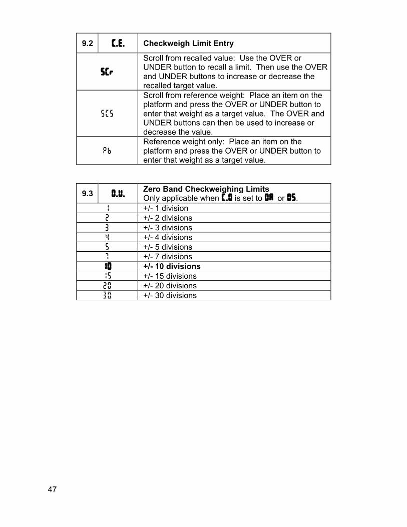
9.2 C.E. Checkweigh Limit Entry
SCr
Scroll from recalled value: Use the OVER or UNDER button to recall a limit. Then use the OVER and UNDER buttons to increase or decrease the recalled target value.
SCS
Scroll from reference weight: Place an item on the platform and press the OVER or UNDER button to enter that weight as a target value. The OVER and UNDER buttons can then be used to increase or decrease the value.
Pb
Reference weight only: Place an item on the platform and press the OVER or UNDER button to enter that weight as a target value.
9.3 0.U. Zero Band Checkweighing Limits Only applicable when C.O is set to 0A or 0S.
1 +/- 1 division 2 +/- 2 divisions 3 +/- 3 divisions 4 +/- 4 divisions 5 +/- 5 divisions 7 +/- 7 divisions 10 +/- 10 divisions 15 +/- 15 divisions 20 +/- 20 divisions 30 +/- 30 divisions

48
9.7 ouT Output Configuration
no Do not enter Output selection menu yes Enter menu
o1-8 Output Configuration o1 off Output is deactivated
o1 THs Weight below threshold level (2.5 tHs) used for output logic
o1 in1 Remote Switch Input Logic 1 used for output logic
o1 in2 Remote Switch Input Logic 2 used for output logic
o1 Lo Low annunciator used for output logic o1 udr Under annunciator used for output logic o1 Acc Accept annunciator used for output logic o1 our Over annunciator used for output logic o1 Hi High annunciator used for output logic
Exit – 99 don
10.1 done Exit and save changes
n Do not exit Y Save changes and exit
49
Data Communications To confirm data has been transmitted, the display will show a "r" in the leftmost digit. Transmit on Demand (tod) In this mode, scale data is transmitted whenever PRINT is pressed, a remote switch configured for a PRINT command is pressed, or a print request is received at the serial port. The scale must be stable and the scale value must be valid before transmission. Timer 1 (t1) Transmits every 1 second. Timer 5 (t5) Transmits every 5 seconds. Timer 60 (t60) Transmits every 60 seconds. Continuous Data Transmission (CP) Data is transmitted each time the scale display updates. Readings which occur when the scale is in motion are indicated out by the abbreviation "MOT." after the weight data. Auto Print 1 (AP1) Auto Print 1 transmits the first stable scale reading each time the scale leaves motion. Auto Print 2 (AP2) Auto Print 2 transmits the first stable scale reading following the scale leaving motion and above the adjustable threshold level. To adjust the Threshold level as a % of capacity, see the Threshold Level (2.5 tHs) parameter. In Auto Print 2, no further readings will be sent until the scale returns to weight reading that is below the adjustable threshold level. Auto Print 3 (AP3) Auto Print 3 transmits the first stable scale reading following the scale leaving motion, within the ACCEPT band and above the adjustable threshold level. To adjust the Threshold level as a % of capacity, see the Threshold Level (2.5 tHs) parameter. In Auto Print 3, no further readings will be sent until the scale returns to weight reading that is below the adjustable threshold level. Auto Print 4 (AP4) Auto Print 4 transmits the first stable scale reading following the scale leaving motion that is above the adjustable threshold level. Transmission does not occur until the scale returns below the threshold value. To adjust the threshold level as a % of capacity, see the Threshold Level (2.5 tHs) parameter. Auto Print 5 (AP5) Auto Print 5 transmits the last stable scale reading following the scale leaving motion that is above the adjustable threshold level. Transmission does not occur until the scale

50
returns below the threshold value. To adjust the threshold level as a % of capacity, see the Threshold Level (2.5 tHs) parameter.
Data String Formatting Many predefined data formats are available. This allows for flexibility when communicating with a database, printer, remote display or other devices. The LB1-4 custom data strings provide the opportunity to define a custom print string up to 64 characters in length. Note: Lb:oz unit is not supported in data strings.
Print String Description
F0
Standard Output Format <STX><p><xxxx.xx><SP><uu><SP> <MOT><CR><LF> Sample Print String ±--10.05-lb Note: “-” represents a space
<STX> Start of Text (02h) <p> Weight Polarity Negative weight “-”, positive weight space (20h) <xxxx.xx> Weight Data fixed field of 6 digits plus decimal. In overload or underload “-------”. Leading zeros are spaces (20h). <uu> Displayed Units “lb”, “kg”, “oz”, “g” <MOT> (Available only in Continuous print mode) Motion Status Appends “MOT” to the print string when printing while in motion <SP> Line Space (20h) <CR> Carriage Return (0dh) <LF> Line Feed (0Ah)
2d
Dual Unit lb and kg Print Output Format <STX><p><xxxx.xx><SP><uu><SP> <MOT><CR><LF> <(><p><xxxx.xx><SP><kg><SP><)><MOT><CR><LF> Sample Print String ±--10.05-lb ±---4.56-kg Note: “-” represents a space
<STX> Start of Text (02h) <p> Weight Polarity Negative weight “-”, positive weight space (20h) <xxxx.xx> Weight Data fixed field of 6 digits plus decimal. In overload or underload “-------”. Leading zeros are spaces (20h) <uu> Displayed Units “lb”, “kg”, “oz”, “g” <MOT> (Available only in Continuous print mode) Motion Status Appends “MOT” to the print string when printing while in motion <SP> Line Space (20h) <CR> Carriage Return (0dh) <LF> Line Feed (0Ah)
51
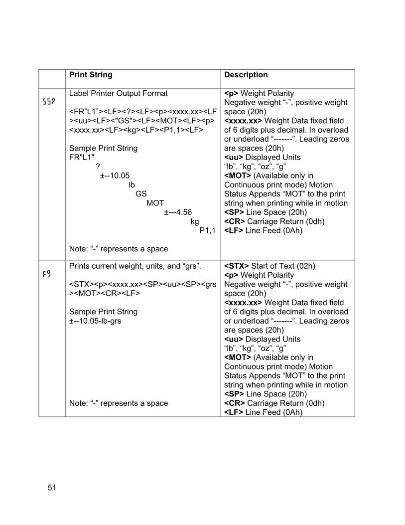
Print String Description
SSP
Label Printer Output Format <FR”L1”><LF><?><LF><p><xxxx.xx><LF><uu><LF><"GS"><LF><MOT><LF><p> <xxxx.xx><LF><kg><LF><P1,1><LF> Sample Print String FR"L1" ? ±--10.05 lb GS MOT ±---4.56 kg P1,1 Note: “-” represents a space
<p> Weight Polarity Negative weight “-”, positive weight space (20h) <xxxx.xx> Weight Data fixed field of 6 digits plus decimal. In overload or underload “-------”. Leading zeros are spaces (20h) <uu> Displayed Units “lb”, “kg”, “oz”, “g” <MOT> (Available only in Continuous print mode) Motion Status Appends “MOT” to the print string when printing while in motion <SP> Line Space (20h) <CR> Carriage Return (0dh) <LF> Line Feed (0Ah)
Fg
Prints current weight, units, and “grs”. <STX><p><xxxx.xx><SP><uu><SP><grs><MOT><CR><LF> Sample Print String ±--10.05-lb-grs Note: “-” represents a space
<STX> Start of Text (02h) <p> Weight Polarity Negative weight “-”, positive weight space (20h) <xxxx.xx> Weight Data fixed field of 6 digits plus decimal. In overload or underload “-------”. Leading zeros are spaces (20h) <uu> Displayed Units “lb”, “kg”, “oz”, “g” <MOT> (Available only in Continuous print mode) Motion Status Appends “MOT” to the print string when printing while in motion <SP> Line Space (20h) <CR> Carriage Return (0dh) <LF> Line Feed (0Ah)

52
Print String Description
Lb1
Custom Data String 1 (\x\w \u \m\r\l) <STX><p><xxxx.xx><SP><uu><SP> <MOT><CR><LF> Sample Print String ±--10.05-lb Note: “-” represents a space
<STX> Start of Text (02h) <p> Weight Polarity Negative weight “-”, positive weight space (20h) <xxxx.xx> Weight Data fixed field of 6 digits plus decimal. In overload or underload “-------”. Leading zeros are spaces (20h) <uu> Displayed Units “lb”, “kg”, “oz”, “g” <MOT> (Available only in Continuous print mode) Motion Status Appends “MOT” to the print string when printing while in motion <SP> Line Space (20h) <CR> Carriage Return (0dh) <LF> Line Feed (0Ah)
Lb2
Custom Data String 2 (\x\w \u \m\r\l) <STX><p><xxxx.xx><SP><uu><SP> <MOT><CR><LF> Sample Print String ±--10.05-lb-ACCEPT Note: “-” represents a space
<STX> Start of Text (02h) <p> Weight Polarity Negative weight “-”, positive weight space (20h) <xxxx.xx> Weight Data fixed field of 6 digits plus decimal. In overload or underload “-------”. Leading zeros are spaces (20h) <uu> Displayed Units “lb”, “kg”, “oz”, “g” <MOT> (Available only in Continuous print mode) Motion Status Appends “MOT” to the print string when printing while in motion <SP> Line Space (20h) <CR> Carriage Return (0dh) <LF> Line Feed (0Ah)

53
Print String Description
Lb3
Custom Data String 3(\xID:\i \w \u \m\r\l) <STX><”ID:”><SP><p><xxxx.xx><SP><uu><SP><MOT><CR><LF> Sample Print String ID:00-±--10.05-lb Note: “-” represents a space
<p> Weight Polarity Negative weight “-”, positive weight space (20h) <xxxx.xx> Weight Data fixed field of 6 digits plus decimal. In overload or underload “-------”. Leading zeros are spaces (20h) <SP> Line Space (20h) <uu> Displayed Units “lb”, “kg”, “oz”, “g” <MOT> (Available only in Continuous print mode , non-LFT) Motion Status Appends “MOT” to the print string when printing while in motion. <CR> Carriage Return (0dh) <LF> Line Feed (0Ah)
Lb4
Custom Data String 4(\a \u \r\l\c\r\lP1\r\l) <accumulator><SP><uu><SP> <CR><LF><counter><CR><LF>”P1” <CR><LF> Sample Print String +--10.05-lb- ----36 P1 Note: “-“ represents a space
<+/-xxxx.xx > Weight Data fixed field of 6 digits plus decimal. In overload or underload “-------”. Leading zeros are spaces (20h) space (20h) <uu> Displayed Units “lb”, “kg”, “oz”, “g” space (20h) <CR> Carriage Return (0dh) <LF> Line Feed (0Ah) <xxxxxx>counter, Leading zeros are spaces (20h) <CR> Carriage Return (0dh) <LF> Line Feed (0Ah) <CR> Carriage Return (0dh) <LF> Line Feed (0Ah)
B0
Prints weight with polarity and units <p><xxxx.xx><SP><uu><SP><CR><LF> Sample Print String ±--10.05-lb Note: “-” represents a space
<p> Weight Polarity Negative weight “-”, positive weight space (20h) <xxxx.xx> Weight Data fixed field of 6 digits plus decimal. In overload or underload “-------”. Leading zeros are spaces (20h). <SP> Line Space (20h) <uu> Displayed Units “lb”, “kg”, “oz”, “g” <CR> Carriage Return (0dh) <LF> Line Feed (0Ah)

54
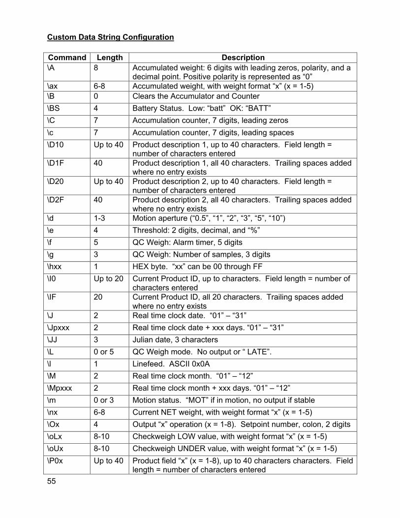
55
Custom Data String Configuration Command Length Description \A 8 Accumulated weight: 6 digits with leading zeros, polarity, and a
decimal point. Positive polarity is represented as “0” \ax 6-8 Accumulated weight, with weight format “x” (x = 1-5) \B 0 Clears the Accumulator and Counter \BS 4 Battery Status. Low: “batt” OK: “BATT” \C 7 Accumulation counter, 7 digits, leading zeros \c 7 Accumulation counter, 7 digits, leading spaces \D10 Up to 40 Product description 1, up to 40 characters. Field length =
number of characters entered \D1F 40 Product description 1, all 40 characters. Trailing spaces added
where no entry exists \D20 Up to 40 Product description 2, up to 40 characters. Field length =
number of characters entered \D2F 40 Product description 2, all 40 characters. Trailing spaces added
where no entry exists \d 1-3 Motion aperture (“0.5”, “1”, “2”, “3”, “5”, “10”) \e 4 Threshold: 2 digits, decimal, and “%” \f 5 QC Weigh: Alarm timer, 5 digits \g 3 QC Weigh: Number of samples, 3 digits \hxx 1 HEX byte. “xx” can be 00 through FF \I0 Up to 20 Current Product ID, up to characters. Field length = number of
characters entered \IF 20 Current Product ID, all 20 characters. Trailing spaces added
where no entry exists \J 2 Real time clock date. “01” – “31” \Jpxxx 2 Real time clock date + xxx days. “01” – “31” \JJ 3 Julian date, 3 characters \L 0 or 5 QC Weigh mode. No output or “ LATE”. \l 1 Linefeed. ASCII 0x0A \M 2 Real time clock month. “01” – “12” \Mpxxx 2 Real time clock month + xxx days. “01” – “12” \m 0 or 3 Motion status. “MOT” if in motion, no output if stable \nx 6-8 Current NET weight, with weight format “x” (x = 1-5) \Ox 4 Output “x” operation (x = 1-8). Setpoint number, colon, 2 digits \oLx 8-10 Checkweigh LOW value, with weight format “x” (x = 1-5) \oUx 8-10 Checkweigh UNDER value, with weight format “x” (x = 1-5) \P0x Up to 40 Product field “x” (x = 1-8), up to 40 characters characters. Field
length = number of characters entered

56
\PFx 40 Product field “x” (x = 1-8), all 40 characters. Trailing spaces added where no entry exists
\P9 5 Product field 9 (counter). 5 digits with leading zeros \pOx 8-10 Checkweigh OVER value, with weight format “x” (x = 1-5)
\pHx 8-10 Checkweigh HIGH value, with weight format “x” (x = 1-5) \qx 6-8 Current GROSS weight, with weight format “x” (x = 1-5) \R 0 Clears TARE and places scale in the GROSS MODE \r 1 Carriage return. ASCII 0x0D \s 6 Checkweigh status. 6 characters with trailing spaces (“LOW ”,
“UNDER “, “ACCEPT”, “OVER “, “HIGH “) \TC 7 12-hour time: HH:MM “AM” or “PM” \Tc 10 12-hour time with seconds: HH:MM:SS “AM” or “PM” \TM 5 24-hour time: HH:MM \Tm 8 24-hour time with seconds: HH:MM:SS \TP 2 “AM” or “PM” \ts 3 Current TARE status, “grs” or “net” \tx 6-8 Current TARE weight, with weight format “x” (x = 1-5) \U Up to 20 User ID. “U:” followed by user ID \u 1-2 Current unit. “lb”, “kg”, “g”, “oz”. \V 1-3 QC weigh mode sample number. “S:” followed by sample
number \W 2 Current weighing mode. “GS” for GROSS and “NT” for NET \wx 6-8 Current weight, with weight format “x” (x = 1-5) \x 1 Start of text character. ASCII 0x02 \Y 2 Real time clock year. ”00” – “99” \Ypxxx 2 Real time clock year + xxx days. “00” – “99” \Y1 1 Least significant digit of year \y 1 Current weight polarity. “-“ or a space \y0 1 Current weight polarity. “-“ or “0” \Z 0 ZERO command “x” Weight Formats 1 8 total characters. Polarity, 6 digits + decimal with leading spaces. 2 8 total characters. Polarity, 6 digits + decimal with leading zeros. 3 7 total characters. No polarity, 6 digits + decimal with leading spaces. 4 7 total characters. No polarity, 6 digits + decimal with leading zeros. 5 6 total characters. No polarity, 6 digits no decimal with leading zeros.
57
Plain text can be inserted into the data string. No control character or slash is necessary for plain text entry. To download a custom data string, the string must be prefaced by a command to tell the indicator to expect a custom print string. ELx<string>¿ Enter (Download) custom data string RLx¿ Read (Upload) custom data string x is the label buffer number (1 to 4) ¿ is carriage return or enter key in terminal program The data string can have up to 62 control characters. For example, the following string is 8 characters in length “\w\u\r\l”. The custom string is terminated and download by pressing the enter. To program this string for Lb1 location in the scale’s memory, send the following string:EL1\w\u\r\l¿ Once programmed, set the Output Format For parameter to lb1 to activate the print string.
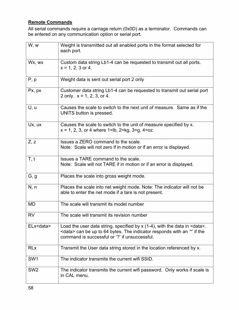
58
Remote Commands All serial commands require a carriage return (0x0D) as a terminator. Commands can be entered on any communication option or serial port. W, w Weight is transmitted out all enabled ports in the format selected for
each port.
Wx, wx Custom data string Lb1-4 can be requested to transmit out all ports. x = 1, 2, 3 or 4.
P, p Weight data is sent out serial port 2 only
Px, px Customer data string Lb1-4 can be requested to transmit out serial port 2 only. x = 1, 2, 3, or 4.
U, u Causes the scale to switch to the next unit of measure. Same as if the UNITS button is pressed.
Ux, ux Causes the scale to switch to the unit of measure specified by x. x = 1, 2, 3, or 4 where 1=lb, 2=kg, 3=g, 4=oz.
Z, z Issues a ZERO command to the scale. Note: Scale will not zero if in motion or if an error is displayed.
T, t Issues a TARE command to the scale. Note: Scale will not TARE if in motion or if an error is displayed.
G, g Places the scale into gross weight mode.
N, n Places the scale into net weight mode. Note: The indicator will not be able to enter the net mode if a tare is not present.
MD The scale will transmit its model number
RV The scale will transmit its revision number
ELx<data> Load the user data string, specified by x (1-4), with the data in <data>. <data> can be up to 64 bytes. The indicator responds with an ‘*’ if the command is successful or ‘?’ if unsuccessful.
RLx Transmit the User data string stored in the location referenced by x.
SW1 The indicator transmits the current wifi SSID.
SW2 The indicator transmits the current wifi password. Only works if scale is in CAL menu.
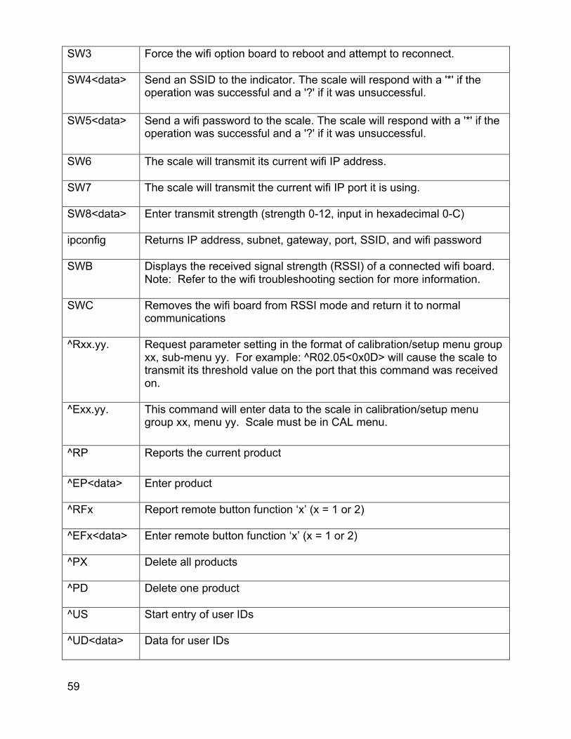
59
SW3 Force the wifi option board to reboot and attempt to reconnect.
SW4<data> Send an SSID to the indicator. The scale will respond with a '*' if the operation was successful and a '?' if it was unsuccessful.
SW5<data> Send a wifi password to the scale. The scale will respond with a '*' if the operation was successful and a '?' if it was unsuccessful.
SW6 The scale will transmit its current wifi IP address.
SW7 The scale will transmit the current wifi IP port it is using.
SW8<data> Enter transmit strength (strength 0-12, input in hexadecimal 0-C)
ipconfig Returns IP address, subnet, gateway, port, SSID, and wifi password
SWB Displays the received signal strength (RSSI) of a connected wifi board. Note: Refer to the wifi troubleshooting section for more information.
SWC Removes the wifi board from RSSI mode and return it to normal communications
^Rxx.yy. Request parameter setting in the format of calibration/setup menu group xx, sub-menu yy. For example: ^R02.05<0x0D> will cause the scale to transmit its threshold value on the port that this command was received on.
^Exx.yy. This command will enter data to the scale in calibration/setup menu group xx, menu yy. Scale must be in CAL menu.
^RP Reports the current product
^EP<data> Enter product
^RFx Report remote button function ‘x’ (x = 1 or 2)
^EFx<data> Enter remote button function ‘x’ (x = 1 or 2)
^PX Delete all products
^PD Delete one product
^US Start entry of user IDs
^UD<data> Data for user IDs
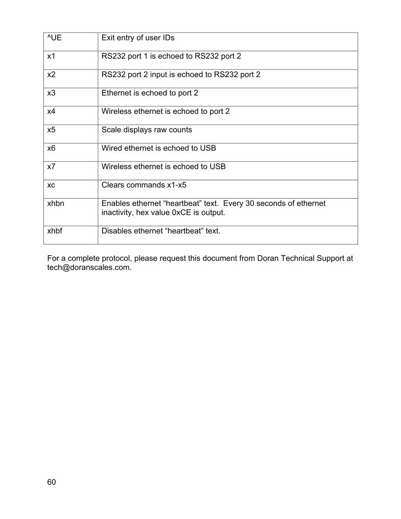
60
^UE Exit entry of user IDs
x1 RS232 port 1 is echoed to RS232 port 2
x2 RS232 port 2 input is echoed to RS232 port 2
x3 Ethernet is echoed to port 2
x4 Wireless ethernet is echoed to port 2
x5 Scale displays raw counts
x6 Wired ethernet is echoed to USB
x7 Wireless ethernet is echoed to USB
xc Clears commands x1-x5
xhbn Enables ethernet “heartbeat” text. Every 30 seconds of ethernet inactivity, hex value 0xCE is output.
xhbf Disables ethernet “heartbeat” text.
For a complete protocol, please request this document from Doran Technical Support at [email protected].

61
Internal Relay Option The Internal Relay Option allows up to four relays to be mounted inside the indicator. Three types of relays are available for use with the Internal Relay Option – 6Vdc Electromechanical and Solid State (AC or DC). Specify style of relay at time of order.
Internal Relay Board
Internal Relay Setup: A twelve conductor cable provides the relay output connections that exits the meter through a watertight. Leave this cable in place when configuring the outputs and refer to the output cable color code table. The Scale does not provide the AC or DC power to run external devices. Each relay has a three-position output that provides a Common, Normally Open and Normally Closed terminal. The Normally Closed terminal is only available for use with a mechanical relay. Solid State relays can operate as Normally Closed through software configuration only. The following table shows the color codes and terminal connections for the included cable.
Relay Specifications: 6VDC Mechanical Relay, 10A 250VAC / 30VDC AC Solid State Relay, 2A 100-240VAC DC Solid State Relay, 2A 5-48VDC

62
Internal Relay Output Cable Color Code Channel Terminal Conductor Color
Relay 1 (OUTPUT 1)
TB201 – NC Red TB201 – COM White TB201 – NO Green
Relay 2 (OUTPUT 2)
TB202 – NC Black TB202 – COM Blue TB202 – NO Brown
Relay 3 (OUTPUT 3)
TB203 – NC Grey TB203 – COM Yellow TB203 – NO Tan
Relay 4 (OUTPUT 4)
TB204 – NC Purple (Pearl) TB204 – COM Pink TB204 – NO Orange
Step-up Relay Circuit If the current load to be switched is greater than the maximum current limit of the internal relay, i.e. 10 Amps for mechanical relay or 2 Amps for Solid State Relay, a step-up relay circuit is required in order to switch to the higher current loads.
63
4-20mA Analog Output Option Introduction The 4-20mA Analog Output Option is used to provide an analog output that is proportional to the weight on the scale platform. The option board provides an active power loop for the communications. The 4-20mA analog output option can be used to send weight data to a process indicator, a simple on/off controller or to a programmable logic controller.
Setup The 4-20mA option is automatically calibrated for an output range of 4mA to 20mA, (i.e. 4mA equals zero weight and 20mA equals the scale’s capacity). Attach the output cable from the 4-20mA option board to an appropriate controller or indicator. The white lead is connected to the + input of TB2 and the black lead is connected to the – input of TB2. Calibrate your process indicator or controller according to the manufacturer's instructions. Remember that the option will output 4mA when the scale reads "zero" and 20mA when the scale reads full capacity.
Operation There is no effect on scale operation, when the 4-20mA Analog Output option is installed, except for battery units which will see a reduction in battery life of approximately 50%.
64
Wired Ethernet Option The Ethernet module is installed inside the indicator enclosure. The NEMA4X sealed RJ-45 Ethernet connector is bulkhead mounted to the rear panel of the indicator. The Wired Ethernet Option auto senses 10/100Base–T networks. The Wired Ethernet Option is fully compliant with the 10/100Base-T Ethernet network standard, transferring data up to 100Mbps. Once the scale is connected you can collect data, remotely configure, or monitor the scale from any computer on the network.
Specifications Hardware:
Bulkhead mount NEMA4X sealed RJ-45 connector Network Interface:
10/100Base-T Ethernet protocol, Data rates up to 100Mbps Static IP DHCP
Options:
Washdown Safe RJ-45 Ethernet Connector Field Install Kit

65
Wireless 802.11b/g Ethernet Option The Wireless Ethernet Option is fully compliant with the 802.11b/g wireless network standard. Wireless communications are protected by up to a 128-bit security encryption. Specifications Hardware: Bulkhead mount 2.4 GHz Dipole Antenna Network Interface:
802.11b/g Ethernet Protocol Static IP DHCP 2.4 GHz Frequency 12dBm Transmitting Power Receiving Sensitivity -83dBm(Typ.)
Wireless Security: WEP-128, WPA-PSK (TKIP), WPA2-PSK (AES) Regulatory Approval: FCC ID: T9J-RN171
This equipment has been tested and found to comply with the limits for a Class B digital device, pursuant to part 15 of the FCC Rules. These limits are designed to provide reasonable protection against harmful interference in a residential installation. This equipment generates, uses and can radiate radio frequency energy, and if not installed and used in accordance with the instructions, may cause harmful interference to radio communications. However, there is no guarantee that interference will not occur in a particular installation. If this equipment does cause harmful interference to radio or television reception, which can be determined by turning the equipment off and on, the user is encouraged to try to correct the interference by one or more of the following measures:
• Reorient or relocate the receiving antenna • Increase the separation between the equipment and receiver • Connect the equipment into an outlet on a circuit different from that to which the
receiver is connected • Consult the dealer or an experienced radio technician for help
66
Troubleshooting Wifi If WIFI is not functioning, try the following procedures: Confirm IP Configuration Enter the scale’s calibration mode (as detailed on page 24) and navigate to parameter group 6 for WIFI. Press ZERO to enter the group, then use UNITS and PRINT to navigate within this group. Ensure that:
• d.o.uu is not set to off • The ip address is properly set • The subnet mask is properly set • The ip gateway is properly set • The port is properly set
Confirm WIFI connection Enter the scale’s calibration mode (see Scale Parameter Setup) and navigate to parameter group 6 for WIFI. Press ZERO to enter the group, then use UNITS and PRINT to navigate within this group. Navigate to the final parameter “CS”. If it reads:
8 – The unit is not connected 88 – The unit is connecting 888 – The unit is connected
If the scale is having trouble connecting, consider repositioning the scale and its antenna to strengthen the connection. Once the scale is connected to Doran’s terminal program Dimension, the exact signal strength can be found using the SWB remote command. See the below table for a guide to this signal strength: Quality: Wifi decibel value: Excellent Greater than -60dB Good -60dB – -75dB Poor Less than -75dB

67
Bluetooth Option Doran Scale’s Bluetooth option is a Class 3, Bluetooth 4.0, configured for SPP. The Bluetooth option does not require any external antenna for communication. Once paired, the Bluetooth module will function as a wireless RS232 serial cable. Each Bluetooth module has an individual 12-digit address i.e. “34:81:F4:13:C8:CE”.
Computer Setup To connect the scale’s Bluetooth module with your computer; the computer will need to have a Bluetooth device installed. Some computers may or may not have a Bluetooth option. If there is no existing Bluetooth device, a Bluetooth USB dongle can be used. Follow the instructions included with the Bluetooth dongle software to setup the computer.
Bluetooth USB Dongle Since Bluetooth software drivers and hardware varies among manufacturers, it is recommended to use the USB Bluetooth dongle available from Doran. Support is not available if the customer is not using the Doran supplied USB dongle.
Pairing Devices (Scale) The scale’s Bluetooth module must be paired with your computer to communicate properly. Turn on the scale with the Bluetooth option installed. Be sure to have the scale near the computer to prevent any interference with communication while configuring the Bluetooth module. Wait 30 seconds after the scale is powered up to allow the scale’s Bluetooth module to become available.
Bluetooth Specifications Feature Implementation Bluetooth Transmission: Class 3 Fully Bluetooth: Bluetooth SIG QDID: B021961 Range: Up to 10 meters Frequency: 2.402 – 2.480 GHz Transmit Power: +2dBm (typ.) Receive Sensitivity: -90dBm (Classic); -92dBm (LE) Profile: SPP Serial Port Profile
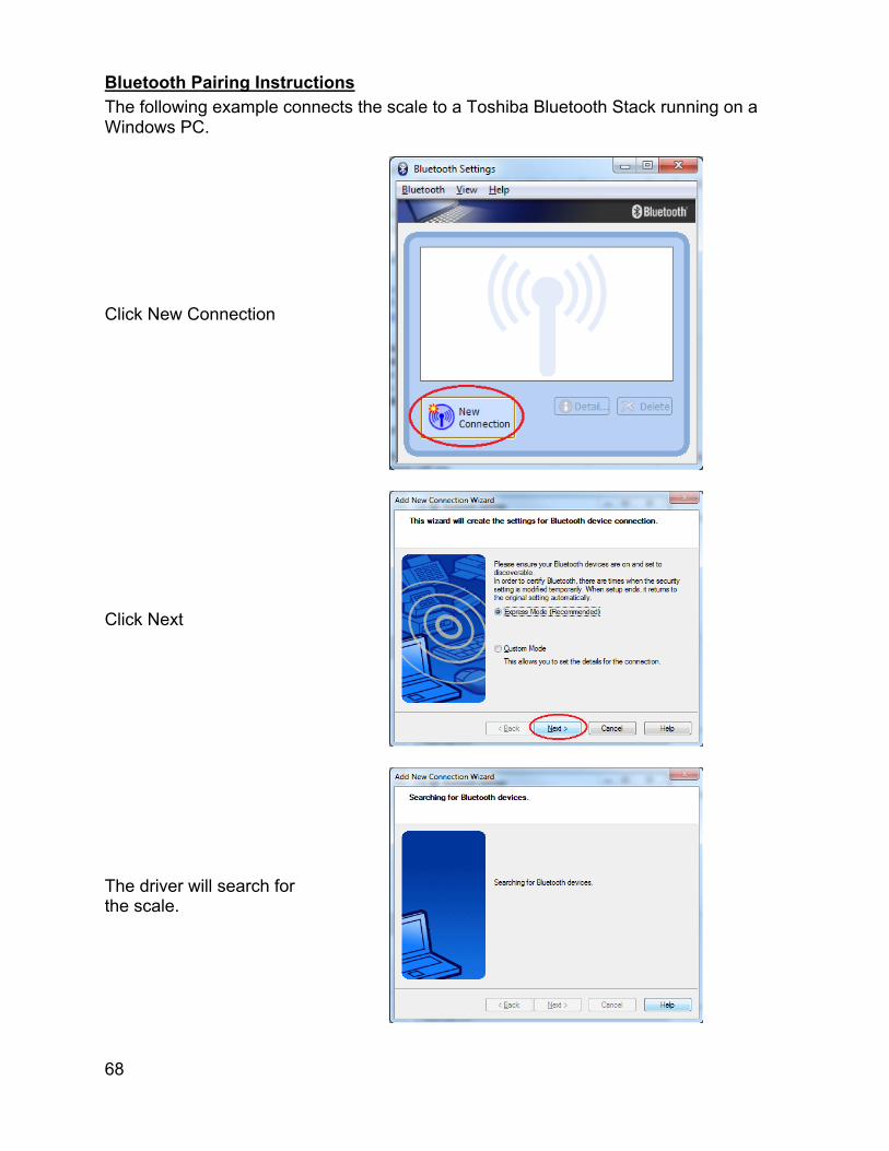
68
Bluetooth Pairing Instructions The following example connects the scale to a Toshiba Bluetooth Stack running on a Windows PC.
Click New Connection
Click Next
The driver will search for the scale.

69
Select Dual-SPP and click Next
Click Next once to pair
Right-click Dual-SPP and choose Connect

70
Click Yes to connect
Right-click Dual-SPP and choose Detail…

71
The COM number will be displayed
Right-click Dual-SPP and choose Connect

72
Troubleshooting If any problem persists, contact Doran Tech Support at [email protected] Problem What to Do or Check Weight reading will not repeat or does not return to zero when weight is removed
Examine the weighing platform for any interferences. Be sure that nothing is inside the platform, under the load cell or the weigh bridge structure
Scale overloads before reaching full capacity
Make sure all four corner overload stops are properly set, if present. Take the platter off the scale, invert it and place it on the platform. With 1/2 of the scale's capacity in test weights concentrated over a corner of the platform, there should be approximately 1/32" of clearance between the stop and the bottom of the spider. Check all four corners then recalibrate the scale.
Scale will not indicate full capacity or go into overload
Make sure that there is nothing caught in the scale under or around the load cell or spider, which would interfere with their movement. If not, check the overload stops using the above procedure.
Scale will not zero when the ZERO button is pressed
Make sure that the scale is stable ( annunciator is off) when ZERO is pressed. If excessive motion is a problem, then it may be necessary to activate the Zero on Demand or change the Display Filter parameter.
Weight readings don't seem to be correct
Check the scale's accuracy with a test weight. Recalibrate if necessary.
Scale drifts off of zero
Check for air currents and/or vibration around the scale. If that is the cause, it may be necessary to set the AZT parameter to a wider setting to compensate
Scale reading is bouncing
Check for air currents and/or vibration around the scale. If that is the cause, it may be necessary to change the Display Filter parameter.
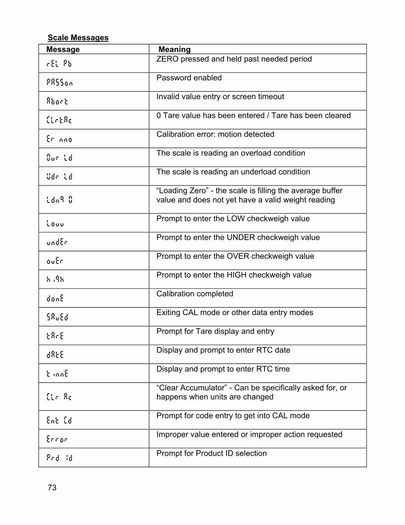
73
Scale Messages Message Meaning
Rel pb ZERO pressed and held past needed period
Passon Password enabled
Abort Invalid value entry or screen timeout
ClrtAc 0 Tare value has been entered / Tare has been cleared
Er nno Calibration error: motion detected
Ovr Ld The scale is reading an overload condition
Udr Ld The scale is reading an underload condition
Ldn9 0
“Loading Zero” - the scale is filling the average buffer value and does not yet have a valid weight reading
Louu Prompt to enter the LOW checkweigh value
undEr Prompt to enter the UNDER checkweigh value
ovEr Prompt to enter the OVER checkweigh value
hi9h Prompt to enter the HIGH checkweigh value
donE Calibration completed
SavEd Exiting CAL mode or other data entry modes
tArE Prompt for Tare display and entry
dAtE Display and prompt to enter RTC date
tinnE Display and prompt to enter RTC time
CLr Ac
“Clear Accumulator” - Can be specifically asked for, or happens when units are changed
Ent CD Prompt for code entry to get into CAL mode
Error Improper value entered or improper action requested
Prd Id Prompt for Product ID selection

74
nEUU New Product ID saved from the front panel
Clr Id Product ID deleted from the front panel
PF 1 – PF 2 Prompt for entry of Product Fields 1 – 9
Error no USEr
Invalid user ID entered in QC Weigh or Production Sentry mode
Out OC Automatic exit of QC Weigh mode
Default to Factory Settings To return the setup parameters to factory default, follow these steps.
1. Enter Calibration Front Panel Access
1. Press and hold ZERO and UNITS simultaneously until the audit counters are displayed.
2. Ent Cd is displayed 3. Press ZERO 5 times, so that 5 is displayed, 4. Press UNITS
Internal Calibration Button
The calibration push button is located near the center of the board and labeled CAL. Press this button to enter calibration and setup.
2. Press ZERO to enter the 2 Cnfg parameter group 3. Press UNITS to scroll to menu item dEFt n. 4. Press ZERO to change selection to dEFt y. 5. Press UNITS to advance. The display will return to dEFt n. 6. Press ZERO to change selection to dEFt y. 7. Press UNITS to advance. 8. The scale will then show SAVEd. 9. After the SAVEd message is displayed, the scale then performs its normal power
up routine and enters the Calibration mode. At this time, all the parameters will have been reset to their factory default settings.
Scale Default Settings When reset to default settings, the CAL menu items, setpoints/outputs, and product ID’s are reset. The scale will maintain the calibration settings previously used. A reference for each CAL menu default value can be found the Scale Paremeter Menu Setup, listed in bold.

Doran Scales, Inc. 883 Enterprise Court St. Charles, IL 60174
www.doranscales.com