MAN0010407 Revision D
128
For Research Use Only. Not for use in diagnostic procedures. QuantStudio ™ 3 and 5 Real‑Time PCR Systems INSTALLATION, USE, AND MAINTENANCE Firmware v1.4 Publication Number MAN0010407 Revision D.0
Transcript of MAN0010407 Revision D

For Research Use Only. Not for use in diagnostic procedures.
QuantStudio™ 3 and 5 Real‑Time PCRSystemsINSTALLATION, USE, AND MAINTENANCE
Firmware v1.4Publication Number MAN0010407
Revision D.0

Life Technologies Holdings Pte Ltd | Block 33 | Marsiling Industrial Estate Road 3 | #07-06, Singapore 739256For descriptions of symbols on product labels or product documents, go to thermofisher.com/symbols-definition.
The information in this guide is subject to change without notice.
DISCLAIMER: TO THE EXTENT ALLOWED BY LAW, THERMO FISHER SCIENTIFIC INC. AND/OR ITS AFFILIATE(S) WILL NOT BELIABLE FOR SPECIAL, INCIDENTAL, INDIRECT, PUNITIVE, MULTIPLE, OR CONSEQUENTIAL DAMAGES IN CONNECTION WITH ORARISING FROM THIS DOCUMENT, INCLUDING YOUR USE OF IT.
Revision Date Description
D.0 22 July 2021 Updates – describes new features in Firmware v1.4.x and other changes, including:
• Updated the name of the cloud-based platform to Thermo Fisher™ Connect.
• Added instructions for connecting to the Thermo Fisher™ Connect cloud-basedplatform.
• Updated the firewall instrument-to-computer port number.
• Updated licensing information.
• Added Network and password security requirements section
• Added Perform internal validations before software upgrades section
• Added information for updating the firmware.
• Update operating system to Windows™ 10 (64‑bit).
• Added the MicroAmp™ Optical Film Compression Pad as an optional accessoryfor the 96-well 0.2-mL block when using a MicroAmp™ Optical 96-Well ReactionPlate, including instructions to load and unload the plate if using this accessory.
• Specified that an instrument profile is only for the instrument. It is not related toany other account for the system or the software.
• Specified that if the connection between the instrument and the desktop softwareis interrupted during a run, the instrument will complete the run. The EDS file mustbe transferred manually to the desktop software with a USB drive or through anetwork drive.
• Changed all references to Bleach, 10% solution to Na-hypochlorite (0.1% v/v)solution
• Updated the calibration and verification schedule.
– Specified that Background and Dye calibrations must be performed after anROI/Uniformity calibration.
– Specified ROI/Uniformity calibration invalidates all other calibrations.
– Added that the Background calibration can be used to obtain the mostaccurate data for the removal of background fluorescence.
– Specified that a Background calibration and a Dye calibration do notinvalidate all other calibrations.
– Added a recommendation that RNase P instrument verification beperformed after instrument calibrations.
• Added troubleshooting information for RNase P verification.
• Added troubleshooting information if the connection between the instrument andthe computer is not recognized.
• Added storage and transport conditions to the environmental requirements.
• Specified that restoring factory defaults can only be performed by anadministrator and specified that the most recent valid ROI/Uniformity,Background, and System Dye calibrations are not deleted when factory defaultsare restored.
C.0 December 2015 Updates – describes new features in Firmware v1.2.x, including:
• Updated workflow to create an instrument profile
• Streamlined workflow for connectivity to Thermo Fisher™ Connect
• Improved display of VeriFlex™ Zones
• Plate insert reminder before starting run
• Support for 96-well Fast (0.1 mL) plates

(continued)
Revision Date Description
B.0 September 2015 Updates – describes new features in Firmware v1.1.x, including:
• Experiment runs: monitor real-time data, edit cycle number and lock screenduring a run, view end plot, and support for 384-well plates
• File management: access Network folders, navigate folder structures and savetemplates on instrument, and perform batch actions for file management
• Instrument configuration: support for Security, Audit, and e-Signature (SAE),smart monitoring, and choice of server region
Includes information on software feature comparison, definitions of terms, parts ofmethod, network connection options, experiment types, desktop software installation.
A.0 April 2015 New document. Describes installation, operation, and maintenance of the QuantStudio™
3 and 5 Real‑Time PCR Systems.
Important Licensing Information: These products may be covered by one or more Limited Use Label Licenses. By use of theseproducts, you accept the terms and conditions of all applicable Limited Use Label Licenses.
Trademarks: All trademarks are the property of Thermo Fisher Scientific and its subsidiaries unless otherwise specified. TaqMan is aregistered trademark of Roche Molecular Systems, Inc., used under permission and license. Cy is a registered trademark of GLOBALLIFE SCIENCES SOLUTIONS GERMANY GMBH. Microsoft and Windows are trademarks of Microsoft Corporation. Pentium is atrademark of Intel Corporation. Google and Chrome are trademarks of Google, Inc.
©2021 Thermo Fisher Scientific Inc. All rights reserved.

Contents
About this guide . . . . . . . . . . . . . . . . . . . . . . . . . . . . . . . . . . . . . . . . . . . . . . . . . . . . . . . . . . . 9
Purpose . . . . . . . . . . . . . . . . . . . . . . . . . . . . . . . . . . . . . . . . . . . . . . . . . . . . . . . . . . . . . . . . . . . . . . . . 9
■ CHAPTER 1 Product information . . . . . . . . . . . . . . . . . . . . . . . . . . . . . . . . . . . . . . . . . . . . . . . . 10
Network and password security requirements . . . . . . . . . . . . . . . . . . . . . . . . . . . . . . . . . . . . . 10Network configuration and security . . . . . . . . . . . . . . . . . . . . . . . . . . . . . . . . . . . . . . . . . . 10Password security . . . . . . . . . . . . . . . . . . . . . . . . . . . . . . . . . . . . . . . . . . . . . . . . . . . . . . . . . 10
Perform internal validations before software upgrades . . . . . . . . . . . . . . . . . . . . . . . . . . . . . . 10
Update the instrument firmware . . . . . . . . . . . . . . . . . . . . . . . . . . . . . . . . . . . . . . . . . . . . . . . . . . 11Backup the instrument . . . . . . . . . . . . . . . . . . . . . . . . . . . . . . . . . . . . . . . . . . . . . . . . . . . . . 11
Instrument hardware description . . . . . . . . . . . . . . . . . . . . . . . . . . . . . . . . . . . . . . . . . . . . . . . . . 11Instrument overview . . . . . . . . . . . . . . . . . . . . . . . . . . . . . . . . . . . . . . . . . . . . . . . . . . . . . . . 11Parts of the instrument . . . . . . . . . . . . . . . . . . . . . . . . . . . . . . . . . . . . . . . . . . . . . . . . . . . . . 15
Software description . . . . . . . . . . . . . . . . . . . . . . . . . . . . . . . . . . . . . . . . . . . . . . . . . . . . . . . . . . . 15Instrument, desktop, and cloud software features . . . . . . . . . . . . . . . . . . . . . . . . . . . . . . 15Folders, templates, experiments, and projects . . . . . . . . . . . . . . . . . . . . . . . . . . . . . . . . . 17Third-party software . . . . . . . . . . . . . . . . . . . . . . . . . . . . . . . . . . . . . . . . . . . . . . . . . . . . . . . 18
Network connection options . . . . . . . . . . . . . . . . . . . . . . . . . . . . . . . . . . . . . . . . . . . . . . . . . . . . . 18
Types of runs . . . . . . . . . . . . . . . . . . . . . . . . . . . . . . . . . . . . . . . . . . . . . . . . . . . . . . . . . . . . . . . . . . 19
■ CHAPTER 2 Start, sign on, and configure the instrument . . . . . . . . . . . . . . . . . . . . . 21
Installation and instrument verification . . . . . . . . . . . . . . . . . . . . . . . . . . . . . . . . . . . . . . . . . . . . 21
Precautions for use . . . . . . . . . . . . . . . . . . . . . . . . . . . . . . . . . . . . . . . . . . . . . . . . . . . . . . . . . . . . . 22
Power on the instrument . . . . . . . . . . . . . . . . . . . . . . . . . . . . . . . . . . . . . . . . . . . . . . . . . . . . . . . . 22
Parts of the home screen . . . . . . . . . . . . . . . . . . . . . . . . . . . . . . . . . . . . . . . . . . . . . . . . . . . . . . . 23
Use the instrument without signing in . . . . . . . . . . . . . . . . . . . . . . . . . . . . . . . . . . . . . . . . . . . . . 25
Create a new instrument profile . . . . . . . . . . . . . . . . . . . . . . . . . . . . . . . . . . . . . . . . . . . . . . . . . . 25
Sign in . . . . . . . . . . . . . . . . . . . . . . . . . . . . . . . . . . . . . . . . . . . . . . . . . . . . . . . . . . . . . . . . . . . . . . . . 25
Sign out . . . . . . . . . . . . . . . . . . . . . . . . . . . . . . . . . . . . . . . . . . . . . . . . . . . . . . . . . . . . . . . . . . . . . . 26
Configure instrument settings . . . . . . . . . . . . . . . . . . . . . . . . . . . . . . . . . . . . . . . . . . . . . . . . . . . . 26
4 QuantStudio™ 3 and 5 Real‑Time PCR Systems Installation, Use, and Maintenance Guide

■ CHAPTER 3 Create and run experiments on the instrument . . . . . . . . . . . . . . . . . . 29
Workflow . . . . . . . . . . . . . . . . . . . . . . . . . . . . . . . . . . . . . . . . . . . . . . . . . . . . . . . . . . . . . . . . . . . . . 29
Options for running an experiment . . . . . . . . . . . . . . . . . . . . . . . . . . . . . . . . . . . . . . . . . . . . . . . 30Create and run an experiment from a template . . . . . . . . . . . . . . . . . . . . . . . . . . . . . . . . 30Run an experiment from a saved file . . . . . . . . . . . . . . . . . . . . . . . . . . . . . . . . . . . . . . . . . 30Repeat the last instrument run . . . . . . . . . . . . . . . . . . . . . . . . . . . . . . . . . . . . . . . . . . . . . . . 31
Edit an experiment before starting a run . . . . . . . . . . . . . . . . . . . . . . . . . . . . . . . . . . . . . . . . . . 32Enter or edit template properties . . . . . . . . . . . . . . . . . . . . . . . . . . . . . . . . . . . . . . . . . . . . . 32Edit the run method . . . . . . . . . . . . . . . . . . . . . . . . . . . . . . . . . . . . . . . . . . . . . . . . . . . . . . . . 33Define, assign, and view well details . . . . . . . . . . . . . . . . . . . . . . . . . . . . . . . . . . . . . . . . . 36
Load and unload the plate . . . . . . . . . . . . . . . . . . . . . . . . . . . . . . . . . . . . . . . . . . . . . . . . . . . . . . 37Load and unload a plate in the instrument . . . . . . . . . . . . . . . . . . . . . . . . . . . . . . . . . . . . 37Load and unload a plate in the instrument with a compression pad . . . . . . . . . . . . . . 38
View, pause, or stop a run . . . . . . . . . . . . . . . . . . . . . . . . . . . . . . . . . . . . . . . . . . . . . . . . . . . . . . . 40View real-time data and plots on the instrument touchscreen . . . . . . . . . . . . . . . . . . . . 40Pause or stop an instrument run . . . . . . . . . . . . . . . . . . . . . . . . . . . . . . . . . . . . . . . . . . . . . 40Adjust the display of real-time plots on the instrument touchscreen . . . . . . . . . . . . . . 41Lock the touchscreen during a run . . . . . . . . . . . . . . . . . . . . . . . . . . . . . . . . . . . . . . . . . . . 41
Transfer, view, or manage files and results . . . . . . . . . . . . . . . . . . . . . . . . . . . . . . . . . . . . . . . . . 41Transfer EDS files from the instrument home screen . . . . . . . . . . . . . . . . . . . . . . . . . . . . 41View run history and delete or transfer files from the instrument . . . . . . . . . . . . . . . . . 42Manage templates (EDT files) . . . . . . . . . . . . . . . . . . . . . . . . . . . . . . . . . . . . . . . . . . . . . . . . 42
■ CHAPTER 4 Calibrate and verify instrument performance . . . . . . . . . . . . . . . . . . . . . 43
Calibration and verification schedule . . . . . . . . . . . . . . . . . . . . . . . . . . . . . . . . . . . . . . . . . . . . . 43
Calibration descriptions . . . . . . . . . . . . . . . . . . . . . . . . . . . . . . . . . . . . . . . . . . . . . . . . . . . . . . . . . 44
View the calibration status and set reminders . . . . . . . . . . . . . . . . . . . . . . . . . . . . . . . . . . . . . . 45View calibration status and set reminders in the instrument . . . . . . . . . . . . . . . . . . . . . 45View calibration status and set reminders in Thermo Fisher™ Connect . . . . . . . . . . . . 45
Perform ROI/uniformity, background, and dye calibrations . . . . . . . . . . . . . . . . . . . . . . . . . . 46Workflow: Calibration . . . . . . . . . . . . . . . . . . . . . . . . . . . . . . . . . . . . . . . . . . . . . . . . . . . . . . 46Prepare a calibration plate . . . . . . . . . . . . . . . . . . . . . . . . . . . . . . . . . . . . . . . . . . . . . . . . . . 47Perform calibrations . . . . . . . . . . . . . . . . . . . . . . . . . . . . . . . . . . . . . . . . . . . . . . . . . . . . . . . . 48View calibration images and transfer results to USB . . . . . . . . . . . . . . . . . . . . . . . . . . . . 50Troubleshoot calibration failure . . . . . . . . . . . . . . . . . . . . . . . . . . . . . . . . . . . . . . . . . . . . . . 51Identify contamination . . . . . . . . . . . . . . . . . . . . . . . . . . . . . . . . . . . . . . . . . . . . . . . . . . . . . . 52Create a background plate (optional) . . . . . . . . . . . . . . . . . . . . . . . . . . . . . . . . . . . . . . . . . 52
Perform instrument verification using RNase P plates . . . . . . . . . . . . . . . . . . . . . . . . . . . . . . . 53Instrument verification description . . . . . . . . . . . . . . . . . . . . . . . . . . . . . . . . . . . . . . . . . . . 53RNase P instrument verification plate . . . . . . . . . . . . . . . . . . . . . . . . . . . . . . . . . . . . . . . . 53Performance specifications pass criteria . . . . . . . . . . . . . . . . . . . . . . . . . . . . . . . . . . . . . . 55Prepare an RNase P plate . . . . . . . . . . . . . . . . . . . . . . . . . . . . . . . . . . . . . . . . . . . . . . . . . . . 55
Contents
QuantStudio™ 3 and 5 Real‑Time PCR Systems Installation, Use, and Maintenance Guide 5

Perform RNase P verification . . . . . . . . . . . . . . . . . . . . . . . . . . . . . . . . . . . . . . . . . . . . . . . . 56Troubleshoot verification failure . . . . . . . . . . . . . . . . . . . . . . . . . . . . . . . . . . . . . . . . . . . . . . 57
Calibrate custom dyes . . . . . . . . . . . . . . . . . . . . . . . . . . . . . . . . . . . . . . . . . . . . . . . . . . . . . . . . . . 59Custom dyes overview . . . . . . . . . . . . . . . . . . . . . . . . . . . . . . . . . . . . . . . . . . . . . . . . . . . . . 59Use a dilution series to determine an optimal custom dye concentration . . . . . . . . . . 59Calibrate the custom dye . . . . . . . . . . . . . . . . . . . . . . . . . . . . . . . . . . . . . . . . . . . . . . . . . . . 62
Calibrate for a custom melt curve experiment . . . . . . . . . . . . . . . . . . . . . . . . . . . . . . . . . . . . . . 65
■ CHAPTER 5 Maintain the instrument . . . . . . . . . . . . . . . . . . . . . . . . . . . . . . . . . . . . . . . . . . . . 67
Backup or restore the instrument . . . . . . . . . . . . . . . . . . . . . . . . . . . . . . . . . . . . . . . . . . . . . . . . 67
Decontaminate the sample block . . . . . . . . . . . . . . . . . . . . . . . . . . . . . . . . . . . . . . . . . . . . . . . . 68Materials required . . . . . . . . . . . . . . . . . . . . . . . . . . . . . . . . . . . . . . . . . . . . . . . . . . . . . . . . . . 68Clean the sample block . . . . . . . . . . . . . . . . . . . . . . . . . . . . . . . . . . . . . . . . . . . . . . . . . . . . . 68Detailed procedures for cleaning the sample block . . . . . . . . . . . . . . . . . . . . . . . . . . . . . 70
Replace the instrument fuses . . . . . . . . . . . . . . . . . . . . . . . . . . . . . . . . . . . . . . . . . . . . . . . . . . . . 71Materials required . . . . . . . . . . . . . . . . . . . . . . . . . . . . . . . . . . . . . . . . . . . . . . . . . . . . . . . . . . 71Replace the fuses . . . . . . . . . . . . . . . . . . . . . . . . . . . . . . . . . . . . . . . . . . . . . . . . . . . . . . . . . . 71
Power on or off, store, and move . . . . . . . . . . . . . . . . . . . . . . . . . . . . . . . . . . . . . . . . . . . . . . . . . 72Enable Sleep Mode . . . . . . . . . . . . . . . . . . . . . . . . . . . . . . . . . . . . . . . . . . . . . . . . . . . . . . . . 72Power on the instrument . . . . . . . . . . . . . . . . . . . . . . . . . . . . . . . . . . . . . . . . . . . . . . . . . . . . 72Power off the instrument . . . . . . . . . . . . . . . . . . . . . . . . . . . . . . . . . . . . . . . . . . . . . . . . . . . . 72Prepare the instrument to store, move, or ship . . . . . . . . . . . . . . . . . . . . . . . . . . . . . . . . . 73Move the instrument . . . . . . . . . . . . . . . . . . . . . . . . . . . . . . . . . . . . . . . . . . . . . . . . . . . . . . . 73Return the instrument for service . . . . . . . . . . . . . . . . . . . . . . . . . . . . . . . . . . . . . . . . . . . . 73
■ CHAPTER 6 Configure the instrument and manage instrument profiles . . . . . 75
Initial start‑up . . . . . . . . . . . . . . . . . . . . . . . . . . . . . . . . . . . . . . . . . . . . . . . . . . . . . . . . . . . . . . . . . . 75
Manage profiles . . . . . . . . . . . . . . . . . . . . . . . . . . . . . . . . . . . . . . . . . . . . . . . . . . . . . . . . . . . . . . . . 76Create an administrator instrument profile during initial start-up . . . . . . . . . . . . . . . . . 76Manage all instrument profiles (Administrator only) . . . . . . . . . . . . . . . . . . . . . . . . . . . . . 76Edit an instrument profile . . . . . . . . . . . . . . . . . . . . . . . . . . . . . . . . . . . . . . . . . . . . . . . . . . . 77
Link an instrument profile to Thermo Fisher™ Connect . . . . . . . . . . . . . . . . . . . . . . . . . . . . . . 77Recommended order to set up profiles . . . . . . . . . . . . . . . . . . . . . . . . . . . . . . . . . . . . . . . 78Overview of local instrument profiles and Thermo Fisher™ Connect profiles . . . . . . . 78Thermo Fisher™ Connect instrument profile roles and functions . . . . . . . . . . . . . . . . . . 79Test the connection to the Thermo Fisher™ Connect platform . . . . . . . . . . . . . . . . . . . . 79Link the instrument to your Thermo Fisher™ Connect account . . . . . . . . . . . . . . . . . . . 80Link a local profile to a Thermo Fisher™ Connect profile . . . . . . . . . . . . . . . . . . . . . . . . . 82Unlink a Thermo Fisher™ Connect account . . . . . . . . . . . . . . . . . . . . . . . . . . . . . . . . . . . . 83If you link when you are signed in to the instrument . . . . . . . . . . . . . . . . . . . . . . . . . . . . 84Change the PIN for a Thermo Fisher™ Connect profile . . . . . . . . . . . . . . . . . . . . . . . . . . 85
Enable SAE mode (Administrator only) . . . . . . . . . . . . . . . . . . . . . . . . . . . . . . . . . . . . . . . . . . . . 85
Require instrument profile sign-in (Administrator only) . . . . . . . . . . . . . . . . . . . . . . . . . . . . . . 86
Contents
6 QuantStudio™ 3 and 5 Real‑Time PCR Systems Installation, Use, and Maintenance Guide

Enable remote instrument monitoring (Administrator only) . . . . . . . . . . . . . . . . . . . . . . . . . . . 86
Update instrument software (Administrator only) . . . . . . . . . . . . . . . . . . . . . . . . . . . . . . . . . . . 86
Restore factory defaults . . . . . . . . . . . . . . . . . . . . . . . . . . . . . . . . . . . . . . . . . . . . . . . . . . . . . . . . . 87
Configure the network . . . . . . . . . . . . . . . . . . . . . . . . . . . . . . . . . . . . . . . . . . . . . . . . . . . . . . . . . . 87Set up a wired connection . . . . . . . . . . . . . . . . . . . . . . . . . . . . . . . . . . . . . . . . . . . . . . . . . . 87Set up a wireless connection . . . . . . . . . . . . . . . . . . . . . . . . . . . . . . . . . . . . . . . . . . . . . . . . 88
Select a region for Thermo Fisher™ Connect (Administrator only) . . . . . . . . . . . . . . . . . . . . . 88
Manage the instrument name (Administrator only) . . . . . . . . . . . . . . . . . . . . . . . . . . . . . . . . . . 88
Set the date and time (Administrator only) . . . . . . . . . . . . . . . . . . . . . . . . . . . . . . . . . . . . . . . . . 89
Manage the Sign Out Timer (Administrator only) . . . . . . . . . . . . . . . . . . . . . . . . . . . . . . . . . . . 89
■ APPENDIX A Install and connect the instrument to a network . . . . . . . . . . . . . . . . 90
Workflow: Install and connect to a network . . . . . . . . . . . . . . . . . . . . . . . . . . . . . . . . . . . . . . . . 90
Before you begin . . . . . . . . . . . . . . . . . . . . . . . . . . . . . . . . . . . . . . . . . . . . . . . . . . . . . . . . . . . . . . . 91
Unpack and install the instrument . . . . . . . . . . . . . . . . . . . . . . . . . . . . . . . . . . . . . . . . . . . . . . . . 91
Power on and follow the startup wizard . . . . . . . . . . . . . . . . . . . . . . . . . . . . . . . . . . . . . . . . . . . 92
Connect the computer to the instrument directly or to a LAN . . . . . . . . . . . . . . . . . . . . . . . . 92
Instrument and computer connections . . . . . . . . . . . . . . . . . . . . . . . . . . . . . . . . . . . . . . . . . . . . 93
Download and install the desktop software . . . . . . . . . . . . . . . . . . . . . . . . . . . . . . . . . . . . . . . . 94Computer requirements for the desktop software . . . . . . . . . . . . . . . . . . . . . . . . . . . . . . 94Download the desktop software . . . . . . . . . . . . . . . . . . . . . . . . . . . . . . . . . . . . . . . . . . . . . 95Install the desktop software . . . . . . . . . . . . . . . . . . . . . . . . . . . . . . . . . . . . . . . . . . . . . . . . . 95
Networking . . . . . . . . . . . . . . . . . . . . . . . . . . . . . . . . . . . . . . . . . . . . . . . . . . . . . . . . . . . . . . . . . . . . 95Supported options for instrument and computer connections . . . . . . . . . . . . . . . . . . . 95Control and monitor networked instruments . . . . . . . . . . . . . . . . . . . . . . . . . . . . . . . . . . . 97Ethernet port overview . . . . . . . . . . . . . . . . . . . . . . . . . . . . . . . . . . . . . . . . . . . . . . . . . . . . . 97Firewall ports that must be open . . . . . . . . . . . . . . . . . . . . . . . . . . . . . . . . . . . . . . . . . . . . . 97Networking guidelines and best practices . . . . . . . . . . . . . . . . . . . . . . . . . . . . . . . . . . . . . 98
■ APPENDIX B Troubleshooting . . . . . . . . . . . . . . . . . . . . . . . . . . . . . . . . . . . . . . . . . . . . . . . . . . . . 99
■ APPENDIX C Parts and materials . . . . . . . . . . . . . . . . . . . . . . . . . . . . . . . . . . . . . . . . . . . . . . 101
Kits, consumables, accessories, and reagents . . . . . . . . . . . . . . . . . . . . . . . . . . . . . . . . . . . . 101
Consumables (96‑well, 0.2‑mL format) . . . . . . . . . . . . . . . . . . . . . . . . . . . . . . . . . . . . . . . . . . . 101
384-well consumables . . . . . . . . . . . . . . . . . . . . . . . . . . . . . . . . . . . . . . . . . . . . . . . . . . . . . . . . . 102
Consumables (96-well, 0.1-mL format) . . . . . . . . . . . . . . . . . . . . . . . . . . . . . . . . . . . . . . . . . . 103
Accessories . . . . . . . . . . . . . . . . . . . . . . . . . . . . . . . . . . . . . . . . . . . . . . . . . . . . . . . . . . . . . . . . . 104
General-use materials and consumables . . . . . . . . . . . . . . . . . . . . . . . . . . . . . . . . . . . . . . . . . 104
Contents
QuantStudio™ 3 and 5 Real‑Time PCR Systems Installation, Use, and Maintenance Guide 7

■ APPENDIX D Instrument specification and layout . . . . . . . . . . . . . . . . . . . . . . . . . . . . 105
Configured system dimensions . . . . . . . . . . . . . . . . . . . . . . . . . . . . . . . . . . . . . . . . . . . . . . . . . 106Instrument clearances . . . . . . . . . . . . . . . . . . . . . . . . . . . . . . . . . . . . . . . . . . . . . . . . . . . . . 107
Electrical requirements . . . . . . . . . . . . . . . . . . . . . . . . . . . . . . . . . . . . . . . . . . . . . . . . . . . . . . . . 107
Environmental requirements . . . . . . . . . . . . . . . . . . . . . . . . . . . . . . . . . . . . . . . . . . . . . . . . . . . . 108
Network requirements . . . . . . . . . . . . . . . . . . . . . . . . . . . . . . . . . . . . . . . . . . . . . . . . . . . . . . . . . 108
■ APPENDIX E Safety . . . . . . . . . . . . . . . . . . . . . . . . . . . . . . . . . . . . . . . . . . . . . . . . . . . . . . . . . . . . . . 110
Symbols on this instrument . . . . . . . . . . . . . . . . . . . . . . . . . . . . . . . . . . . . . . . . . . . . . . . . . . . . 110Conformity symbols . . . . . . . . . . . . . . . . . . . . . . . . . . . . . . . . . . . . . . . . . . . . . . . . . . . . . . 112
Safety alerts on this instrument . . . . . . . . . . . . . . . . . . . . . . . . . . . . . . . . . . . . . . . . . . . . . . . . . 113Location of safety labels on the instrument . . . . . . . . . . . . . . . . . . . . . . . . . . . . . . . . . . 113
Safety information for instruments not manufactured by Thermo Fisher Scientific . . . . . 114
Instrument safety . . . . . . . . . . . . . . . . . . . . . . . . . . . . . . . . . . . . . . . . . . . . . . . . . . . . . . . . . . . . . 114General . . . . . . . . . . . . . . . . . . . . . . . . . . . . . . . . . . . . . . . . . . . . . . . . . . . . . . . . . . . . . . . . . 114Physical injury . . . . . . . . . . . . . . . . . . . . . . . . . . . . . . . . . . . . . . . . . . . . . . . . . . . . . . . . . . . . 115Electrical safety . . . . . . . . . . . . . . . . . . . . . . . . . . . . . . . . . . . . . . . . . . . . . . . . . . . . . . . . . . 116Cleaning and decontamination . . . . . . . . . . . . . . . . . . . . . . . . . . . . . . . . . . . . . . . . . . . . . 116
Safety and electromagnetic compatibility (EMC) standards . . . . . . . . . . . . . . . . . . . . . . . . . 116Safety compliance . . . . . . . . . . . . . . . . . . . . . . . . . . . . . . . . . . . . . . . . . . . . . . . . . . . . . . . . 117EMC . . . . . . . . . . . . . . . . . . . . . . . . . . . . . . . . . . . . . . . . . . . . . . . . . . . . . . . . . . . . . . . . . . . . 117Environmental design . . . . . . . . . . . . . . . . . . . . . . . . . . . . . . . . . . . . . . . . . . . . . . . . . . . . . 118
Chemical safety . . . . . . . . . . . . . . . . . . . . . . . . . . . . . . . . . . . . . . . . . . . . . . . . . . . . . . . . . . . . . . 119
Biological hazard safety . . . . . . . . . . . . . . . . . . . . . . . . . . . . . . . . . . . . . . . . . . . . . . . . . . . . . . . 120
■ APPENDIX F Documentation and support . . . . . . . . . . . . . . . . . . . . . . . . . . . . . . . . . . . . . 121
Related documentation . . . . . . . . . . . . . . . . . . . . . . . . . . . . . . . . . . . . . . . . . . . . . . . . . . . . . . . . 121
Obtain information from the Help system . . . . . . . . . . . . . . . . . . . . . . . . . . . . . . . . . . . . . . . . 122
Customer and technical support . . . . . . . . . . . . . . . . . . . . . . . . . . . . . . . . . . . . . . . . . . . . . . . . 122
Limited product warranty . . . . . . . . . . . . . . . . . . . . . . . . . . . . . . . . . . . . . . . . . . . . . . . . . . . . . . 122
Index . . . . . . . . . . . . . . . . . . . . . . . . . . . . . . . . . . . . . . . . . . . . . . . . . . . . . . . . . . . . . . . . . . . . . . . . . . . . . . . . . . . . . 123
Contents
8 QuantStudio™ 3 and 5 Real‑Time PCR Systems Installation, Use, and Maintenance Guide

About this guide
PurposeThis guide provides information about installing, using, and maintaining the QuantStudio™ 3 and 5Real‑Time PCR Systems.
Note: For information and instructions on performing experiments on these systems, see QuantStudio™
Design and Analysis Desktop Software User Guide (Pub. No. MAN0010408).
QuantStudio™ 3 and 5 Real‑Time PCR Systems Installation, Use, and Maintenance Guide 9

Product information
■ Network and password security requirements . . . . . . . . . . . . . . . . . . . . . . . . . . . . . . . . . . . . . . . . . . . . 10
■ Perform internal validations before software upgrades . . . . . . . . . . . . . . . . . . . . . . . . . . . . . . . . . . . . . 10
■ Update the instrument firmware . . . . . . . . . . . . . . . . . . . . . . . . . . . . . . . . . . . . . . . . . . . . . . . . . . . . . . . . 11
■ Instrument hardware description . . . . . . . . . . . . . . . . . . . . . . . . . . . . . . . . . . . . . . . . . . . . . . . . . . . . . . . 11
■ Software description . . . . . . . . . . . . . . . . . . . . . . . . . . . . . . . . . . . . . . . . . . . . . . . . . . . . . . . . . . . . . . . . . . 15
■ Network connection options . . . . . . . . . . . . . . . . . . . . . . . . . . . . . . . . . . . . . . . . . . . . . . . . . . . . . . . . . . . 18
■ Types of runs . . . . . . . . . . . . . . . . . . . . . . . . . . . . . . . . . . . . . . . . . . . . . . . . . . . . . . . . . . . . . . . . . . . . . . . . 19
Network and password security requirements
Network configuration and security
The network configuration and security settings of your laboratory or facility (such as firewalls, anti-virus software, network passwords) are the sole responsibility of your facility administrator, IT, andsecurity personnel. This product does not provide any network or security configuration files, utilities, orinstructions.
If external or network drives are connected to the software, it is the responsibility of your IT personnelto ensure that such drives are configured and secured correctly to prevent data corruption or loss. Itis the responsibility of your facility administrator, IT, and security personnel to prevent the use of anyunsecured ports (such as USB, Ethernet) and ensure that the system security is maintained.
Password security
Thermo Fisher Scientific strongly recommends that you maintain unique passwords for all accounts inuse on this product. All passwords should be reset upon first sign in to the product. Change passwordsaccording to your organization's password policy.
It is the sole responsibility of your IT personnel to develop and enforce secure use of passwords.
Perform internal validations before software upgrades
IMPORTANT! If you have a validated workflow, you must perform all internal validations as required byyour organization's standard operating procedures before performing a software upgrade.
1
10 QuantStudio™ 3 and 5 Real‑Time PCR Systems Installation, Use, and Maintenance Guide
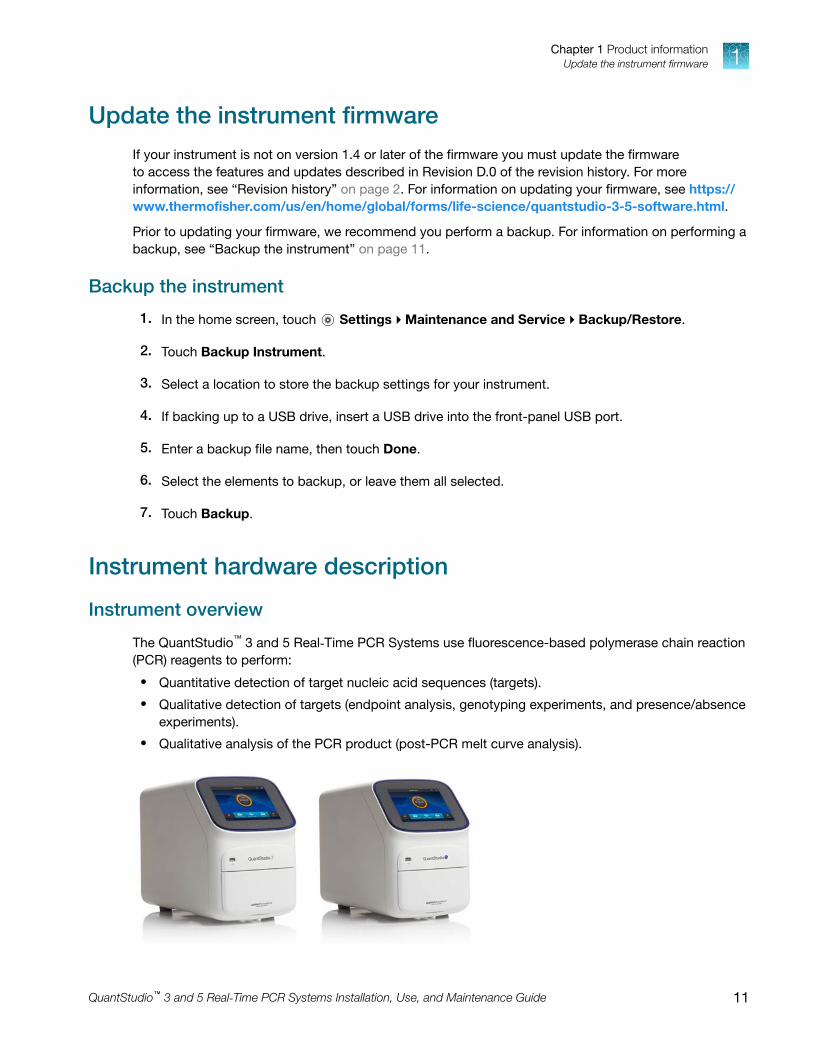
Update the instrument firmwareIf your instrument is not on version 1.4 or later of the firmware you must update the firmwareto access the features and updates described in Revision D.0 of the revision history. For moreinformation, see “Revision history” on page 2. For information on updating your firmware, see https://www.thermofisher.com/us/en/home/global/forms/life-science/quantstudio-3-5-software.html.
Prior to updating your firmware, we recommend you perform a backup. For information on performing abackup, see “Backup the instrument” on page 11.
Backup the instrument
1. In the home screen, touch Settings4Maintenance and Service4Backup/Restore.
2. Touch Backup Instrument.
3. Select a location to store the backup settings for your instrument.
4. If backing up to a USB drive, insert a USB drive into the front-panel USB port.
5. Enter a backup file name, then touch Done.
6. Select the elements to backup, or leave them all selected.
7. Touch Backup.
Instrument hardware description
Instrument overview
The QuantStudio™ 3 and 5 Real‑Time PCR Systems use fluorescence-based polymerase chain reaction(PCR) reagents to perform:
• Quantitative detection of target nucleic acid sequences (targets).
• Qualitative detection of targets (endpoint analysis, genotyping experiments, and presence/absenceexperiments).
• Qualitative analysis of the PCR product (post-PCR melt curve analysis).
Chapter 1 Product informationUpdate the instrument firmware 1
QuantStudio™ 3 and 5 Real‑Time PCR Systems Installation, Use, and Maintenance Guide 11

The following fixed-block configurations are available:
QuantStudio™ 3 Real-Time PCR System QuantStudio™ 5 Real‑Time PCR System
• 96-Well VeriFlex™ 0.2-mL Block (4 Color)
• 96-Well VeriFlex™ 0.1-mL Block (4 Color)
• 96-Well VeriFlex™ 0.2-mL Block(6 Color De‑coupled)
• 384-Well Block (5 Color)
• 96–Well VeriFlex™ 0.1-mL Block(6 Color De‑coupled)
The instrument can be run directly from the touchscreen to create and start experiments. To designexperiments or to analyze data, the instrument can be integrated with the QuantStudio™ Design andAnalysis Software.
An optional barcode scanner and optional wireless adapter can be purchased separately.
Instrument filters and supported dyes
System dyes
The instruments use a coupled four-color, coupled five-color, or de-coupled six-color filter set thatsupports the dyes shown in the following table and figure. For more information about available spectraldye calibration kits, contact Support.
Peak filter ColorFilter wavelength (nm)[1]
Factory-calibrateddyes
Example custom dyesExcitation Emission
x1-m1 Blue 470 ± 15 520 ± 15FAM™ dye,
SYBR™ GreenSYT09
x2-m2 Green 520 ± 10 558 ± 12 VIC™ dyeJOE™ dye,
HEX™ dye, TET™ dye[2]
x3-m3 Yellow 550 ± 10 587 ± 10NED™ dye, TAMRA™
dye, ABY™ dyeCy®3
x4-m4 Orange 580 ± 10 623 ± 14 ROX™ dye, JUN™ dye Texas Red™ dye
x5-m5 Red 640 ± 10 682 ± 14MUSTANG PURPLE™
dye, Cy®5LIZ™ dye
x6-m6 Deep-Red 662 ± 10 711 ± 12 None [3] Cy® 5.5
[1] The central wavelengths are the optimized wavelengths.[2] The HEX™ and TET™ dyes from Thermo Fisher Scientific fall within the emission wavelength range of the system, therefore they can
be added and adapted for use on the instrument.[3] This filter set currently does not support any dyes supplied by Thermo Fisher Scientific.
Chapter 1 Product informationInstrument hardware description1
12 QuantStudio™ 3 and 5 Real‑Time PCR Systems Installation, Use, and Maintenance Guide

Filters
Wavelength(nm)
1 2 3 4 5
x1-m1 x2-m2 x3-m3 x4-m4 x5-m5 x6-m6
EmissionSpectra
1 x1-m1 — FAM™ dye, SYBR™ Green
2 x2-m2 — VIC™ dye
3 x3-m3 — ABY™ dye, NED™ dye, Cy®3, TAMRA™ dye
4 x4-m4 — JUN™ dye, ROX™ dye, Texas Red™ dye
5 x5-m5 — Cy®5, MUSTANG PURPLE™ dye
Custom dyes
The instrument can run assays designed with custom dyes.
Custom dyes include:
• Dyes that are not supplied by Thermo Fisher Scientific.
• Dyes or formulations of dyes that are not system dyes for the instrument.
To use a custom dye on the instrument, review the following requirements.
• Calibrate the instrument for the custom dye (see “Calibrate custom dyes” on page 59).
• Ensure that the custom dye excites between 455 – 672 nm and emits between 505 – 723 nm.
• Select a custom dye that does not overlap with other dyes used in the run (see the filter-wavelength table in “System dyes” on page 12).
• The custom dye must be attached to the 5' end of a short DNA oligonucleotide consisting of thefirst two bases of the probe sequence without a quencher at the 3' end.
Chapter 1 Product informationInstrument hardware description 1
QuantStudio™ 3 and 5 Real‑Time PCR Systems Installation, Use, and Maintenance Guide 13

About data collection
The instrument collects raw fluorescence data at different points during the PCR cycle, depending onthe type of run performed.
When you create an experiment template (EDT file) in the software, you can customize the optical filterchannels through which the instrument collects data. You can specify a filter channel set for all PCRthermal protocols and, optionally, a different filter set for the melt curve stages.
Run type Experiment type Data collection point
Real-time • Standard curve
• Relative standard curve
• Comparative CT (ΔΔCT)
• Melt curve
During the thermal cycling protocol.
Typical timing is to collect data at each cycle of a PCRstage or continuously during a melt stage.
Post-PCR(endpoint)
• Genotyping
• Presence/ Absence
• After thermal cycling is completed.For Presence/Absence and Genotyping experiments,data collection before the PCR cycle is optional, butrecommended.
• (Optional) Before thermal cycling starts.Collecting data during the run can confirmgenotyping results by viewing traces in allelicdiscrimination plots or viewing genotyping calls atearlier cycles.
Blocks with VeriFlex™ Zones
Applied Biosystems™ VeriFlex™ technology provides independent temperature zones that offerenhanced functionality and precise control over your real-time PCR runs.
QuantStudio™ 3 System QuantStudio™ 5 System
Three programmable VeriFlex™ Zones. Six programmable VeriFlex™ Zones.[1]
[1] Only applicable for 96-well 0.2-mL and 0.1-mL blocks.
Chapter 1 Product informationInstrument hardware description1
14 QuantStudio™ 3 and 5 Real‑Time PCR Systems Installation, Use, and Maintenance Guide

These independent zones are ideal for real-time PCR optimization or the ability to run multipleexperiments in the same run. Unlike standard gradients which give a sigmoidal temperature curveacross the columns, blocks with VeriFlex™ Zones help deliver accurate temperatures across every zone.
Parts of the instrument
1
2
3
1 Touchscreen – Controls the instrument.
2 USB port – For connection to an external network drive or external data storage device.
3 Instrument drawer – Contains sample plate.
The instrument includes three additional USB ports on the back of the instrument.
Note: The instrument recognizes only one external storage device at a time for data transfer.
Software description
Instrument, desktop, and cloud software features
The instrument software and the QuantStudio™ Design and Analysis Software (desktop and ThermoFisher™ Connect) include the features described below.
Feature Instrument DesktopThermo Fisher™
Connect
Use as guest (no sign in) ✓ ✓ [1] —
Create templates (unlocked or locked) — ✓ ✓
Edit unlocked templates ✓ ✓ ✓
Edit locked templates (password assigned bytemplate creator required)
— ✓ ✓
Load system or user-created templates (.edt file)to instrument
✓ ✓ —
Chapter 1 Product informationSoftware description 1
QuantStudio™ 3 and 5 Real‑Time PCR Systems Installation, Use, and Maintenance Guide 15

(continued)
Feature Instrument DesktopThermo Fisher™
Connect
Change experiment settings in template (.edt file)loaded on the instrument
Settings that can be changed in a lockedtemplate (no password required):
• Properties: All settings
• Method: No changes allowed
• Plate: Sample names
Settings that can be changed in an unlockedtemplate:
• Properties: All settings
• Method: All settings
• Plate: Sample names
✓ — —
Load plate in instrument ✓ — —
Start run ✓ ✓ —
View real-time data during a run ✓ ✓ ✓
View instrument status (running, calibrationneeded, and so on)
✓ — ✓
Analyze results — ✓ ✓
Set calibration reminders ✓ — ✓
Review exported calibration or RNase Pverification results
— ✓ ✓
(only RNase P)
[1] Login required if the Security, Audit, and e-Signature (SAE) module is enabled (QuantStudio™ 5 System only)
Chapter 1 Product informationSoftware description1
16 QuantStudio™ 3 and 5 Real‑Time PCR Systems Installation, Use, and Maintenance Guide
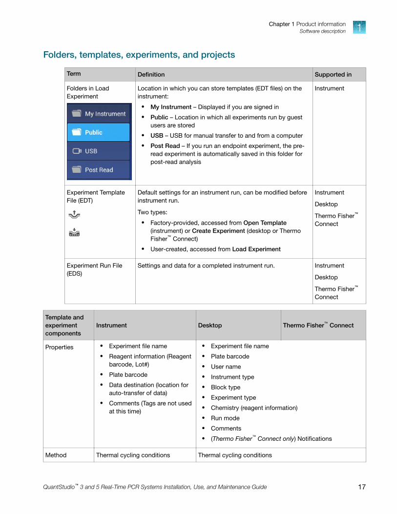
Folders, templates, experiments, and projects
Term Definition Supported in
Folders in LoadExperiment
Location in which you can store templates (EDT files) on theinstrument:
• My Instrument – Displayed if you are signed in
• Public – Location in which all experiments run by guestusers are stored
• USB – USB for manual transfer to and from a computer
• Post Read – If you run an endpoint experiment, the pre-read experiment is automatically saved in this folder forpost-read analysis
Instrument
Experiment TemplateFile (EDT)
Default settings for an instrument run, can be modified beforeinstrument run.
Two types:
• Factory-provided, accessed from Open Template(instrument) or Create Experiment (desktop or ThermoFisher™ Connect)
• User-created, accessed from Load Experiment
Instrument
Desktop
Thermo Fisher™
Connect
Experiment Run File(EDS)
Settings and data for a completed instrument run. Instrument
Desktop
Thermo Fisher™
Connect
Template andexperimentcomponents
Instrument Desktop Thermo Fisher™ Connect
Properties • Experiment file name
• Reagent information (Reagentbarcode, Lot#)
• Plate barcode
• Data destination (location forauto-transfer of data)
• Comments (Tags are not usedat this time)
• Experiment file name
• Plate barcode
• User name
• Instrument type
• Block type
• Experiment type
• Chemistry (reagent information)
• Run mode
• Comments
• (Thermo Fisher™ Connect only) Notifications
Method Thermal cycling conditions Thermal cycling conditions
Chapter 1 Product informationSoftware description 1
QuantStudio™ 3 and 5 Real‑Time PCR Systems Installation, Use, and Maintenance Guide 17

(continued)
Template andexperimentcomponents
Instrument Desktop Thermo Fisher™ Connect
Plate Sample names
You cannot edit targets/SNPassays or tasks on the instrument.
Define and assign samples, targets or SNP assays, andtasks in the Quick Setup and Advanced Setup panes of thePlate tab.
Run Start and monitor a run in progress
View: time remaining andtemperature, method, plots
Pause, resume, stop a run
Start and monitor a run inprogress
View: time remaining andtemperature, method, plots
Monitor a run in progress(link to Thermo Fisher™
Connect Instrument Details)
View: time remaining andtemperature, method, plots
Results Not applicable Review plots
Export Not applicable Export results
Third-party software
Before installing third-party software on the computer running QuantStudio™ Design and AnalysisSoftware, confirm that the third-party software will not do the following:
• Restrict Ethernet communication.
• Interfere with instrument or computer operation.
Network connection optionsYou can connect an instrument to a network or computer in the configurations listed below. For specificinformation on networking, see “Networking” on page 95.
Direct connectionLocal area network (LAN)
connectionThermo Fisher™ Connect
connection
wired wired or wireless wired or wireless
LAN
LAN
LAN
Chapter 1 Product informationNetwork connection options1
18 QuantStudio™ 3 and 5 Real‑Time PCR Systems Installation, Use, and Maintenance Guide

Types of runs
Purpose Description
Standard curve run
Determines absolutetarget quantity insamples.
1. The software measures amplification of the target in a standard dilution series and intest samples.
2. The software generates a standard curve using data from the standard dilution series.
3. The software uses the standard curve to interpolate the absolute quantity of target inthe test samples.
Relative standard curve run
Determines relativetarget quantity insamples.
1. The software measures amplification of the target of interest and of an endogenouscontrol target in a standard dilution series, in a reference (calibrator) sample, and in testsamples.
The endogenous control is a target that is expressed equally in all samples;examples of endogenous controls are β‐actin, GAPDH, and 18S ribosomal RNA. Thesoftware can algorithmically incorporate multiple endogenous control targets in relativequantification calculations.The reference sample is used as the basis for relative quantification results (or1× sample). For example, in a study of drug effects on gene expression, an untreatedcontrol is an appropriate reference sample.
2. The software generates standard curves for the target of interest and the endogenouscontrol using data from the corresponding standard dilution series.
3. The software uses the standard curves to interpolate the quantities of the target ofinterest and the endogenous control in each sample. The target quantity in eachsample is then normalized to the sample's endogenous control quantity.
4. To determine the relative quantity of the target in test samples, the software dividesthe normalized target quantity in the sample by the normalized target quantity in thereference sample.
Comparative Ct (ΔΔCt) run
Determines relativetarget quantity insamples.
1. The software measures amplification of the target of interest and of an endogenouscontrol target in a reference (calibrator) sample and in test samples.The endogenous control is a target that is expressed equally in all samples;examples of endogenous controls are β‐actin, GAPDH, and 18S ribosomal RNA. Thesoftware can algorithmically incorporate multiple endogenous control targets in relativequantification calculations.The reference sample is used as the basis for relative quantification results (or1× sample). For example, in a study of drug effects on gene expression, an untreatedcontrol is an appropriate reference sample.
2. The measurements for the target of interest are normalized to the endogenous control.
3. To determine the relative quantity of the target in test samples, the software comparesthe normalized ΔCq (ΔCt or ΔCrt) for the sample to the normalized ΔCq (ΔCt or ΔCrt) forthe reference sample.
Chapter 1 Product informationTypes of runs 1
QuantStudio™ 3 and 5 Real‑Time PCR Systems Installation, Use, and Maintenance Guide 19

Purpose Description
Genotyping run
Detects singlenucleotidepolymorphism (SNP)variants of atarget nucleic acidsequence.
Genotyping runs use preformulated TaqMan™ SNP Genotyping Assays that include thefollowing components:
• Two sequence-specific primers for amplification of sequences containing the SNP ofinterest
• Two allele-specific TaqMan™ probes for Allele 1 and Allele 2
1. The software normalizes the fluorescence of the reporter dyes to the fluorescence ofthe passive reference dye in each well.
2. The software plots the normalized reporter dye signal of each sample well on an AllelicDiscrimination Plot, which contrasts the reporter dye intensities of the allele-specificprobes.
3. The software algorithmically clusters the sample data, and assigns a genotype call tothe samples of each cluster according to its position on the plot.
Presence/absence run
Determines thepresence or absenceof a target nucleicacid sequence in asample.
The software calls the target present or absent based on an algorithmically determined callthreshold. (The call threshold is different from the Ct threshold; the Ct threshold is not usedto make calls.)
Melt curve run
Determines themelting temperature(Tm) ofthe amplificationproducts of aPCR that usedintercalating dyes.
In the software, melt curve analysis is included in the default run method for any run typethat uses intercalating dyes.
1. The software plots a melt curve based on the fluorescence of the dye with respect tochange in temperature.
2. Using the melt curve, the software calculates the melting temperature (Tm).
Chapter 1 Product informationTypes of runs1
20 QuantStudio™ 3 and 5 Real‑Time PCR Systems Installation, Use, and Maintenance Guide

Start, sign on, and configure theinstrument
■ Installation and instrument verification . . . . . . . . . . . . . . . . . . . . . . . . . . . . . . . . . . . . . . . . . . . . . . . . . . 21
■ Precautions for use . . . . . . . . . . . . . . . . . . . . . . . . . . . . . . . . . . . . . . . . . . . . . . . . . . . . . . . . . . . . . . . . . . . 22
■ Power on the instrument . . . . . . . . . . . . . . . . . . . . . . . . . . . . . . . . . . . . . . . . . . . . . . . . . . . . . . . . . . . . . . 22
■ Parts of the home screen . . . . . . . . . . . . . . . . . . . . . . . . . . . . . . . . . . . . . . . . . . . . . . . . . . . . . . . . . . . . . . 23
■ Use the instrument without signing in . . . . . . . . . . . . . . . . . . . . . . . . . . . . . . . . . . . . . . . . . . . . . . . . . . . 25
■ Create a new instrument profile . . . . . . . . . . . . . . . . . . . . . . . . . . . . . . . . . . . . . . . . . . . . . . . . . . . . . . . . 25
■ Sign in . . . . . . . . . . . . . . . . . . . . . . . . . . . . . . . . . . . . . . . . . . . . . . . . . . . . . . . . . . . . . . . . . . . . . . . . . . . . . . 25
■ Sign out . . . . . . . . . . . . . . . . . . . . . . . . . . . . . . . . . . . . . . . . . . . . . . . . . . . . . . . . . . . . . . . . . . . . . . . . . . . . . 26
■ Configure instrument settings . . . . . . . . . . . . . . . . . . . . . . . . . . . . . . . . . . . . . . . . . . . . . . . . . . . . . . . . . . 26
Installation and instrument verificationBefore the first use of the instrument, complete the following tasks:
• Install the instrument (see “Unpack and install the instrument” on page 91).
• Verify instrument performance (see “Perform instrument verification using RNase P plates” onpage 53).
Note:
· Instruments are factory calibrated, so no calibration is necessary at installation. However, werecommend that you verify instrument performance before using the instrument.
· Regular calibration and verification should be performed according to the calibration andverification schedule (see “Calibration and verification schedule” on page 43).
2
QuantStudio™ 3 and 5 Real‑Time PCR Systems Installation, Use, and Maintenance Guide 21

Precautions for use
CAUTION! PHYSICAL INJURY HAZARD. Do not remove the instrument cover. There are nocomponents inside the instrument that you can safely service yourself. If you suspect a problem,contact technical support.
CAUTION! FIRE HAZARD. For continued protection against the risk of fire, replace fuses only withlisted and certified fuses of the same type and rating as those currently in the instrument.
CAUTION! PHYSICAL INJURY HAZARD. During instrument operation, the sample blocktemperature can reach 100°C. Allow it to cool to room temperature before handling.
CAUTION! Before using a cleaning or decontamination method other than those recommended byThermo Fisher Scientific, confirm with Thermo Fisher Scientific that the proposed method will notdamage the instrument.
CAUTION! Use flat caps for tubes. Rounded caps can damage the heated cover.
Power on the instrument1. Touch anywhere on the touchscreen to determine if the instrument is in sleep mode. If the home
screen is displayed, the instrument is already powered on.
2. If the home screen does not display, power on theinstrument by pressing the switch on the rear panel.
If left unattended, the instrument automatically enters sleepmode (enabled by default) to conserve power.
Note: To customize the sleep mode setting, touch Settings4Instrument Settings4Sleep Mode.
Chapter 2 Start, sign on, and configure the instrumentPrecautions for use2
22 QuantStudio™ 3 and 5 Real‑Time PCR Systems Installation, Use, and Maintenance Guide

Parts of the home screen
4
2
9
1
5
6
8 7
3
1 Avatar and Instrument name
2 Eject icon
3 Help icon
4 Status dial
5 Current user name; instrument block type
6 Settings button
7 Buttons for accessing .edt files
8 Connectivity icons
9 Sign In (or My Profile) button
Table 1 Parts of the home screen
Element of thehome screen
Function For more information, see...
Avatar andInstrument name
Set by the administrator to uniquely identify instrument. “Manage the instrument name(Administrator only)” on page 88.
Eject icon Touch to open or close the instrument drawer. —
Help icon Touch to launch the touchscreen Help system to accessstep-by-step instructions.
—
Chapter 2 Start, sign on, and configure the instrumentParts of the home screen 2
QuantStudio™ 3 and 5 Real‑Time PCR Systems Installation, Use, and Maintenance Guide 23
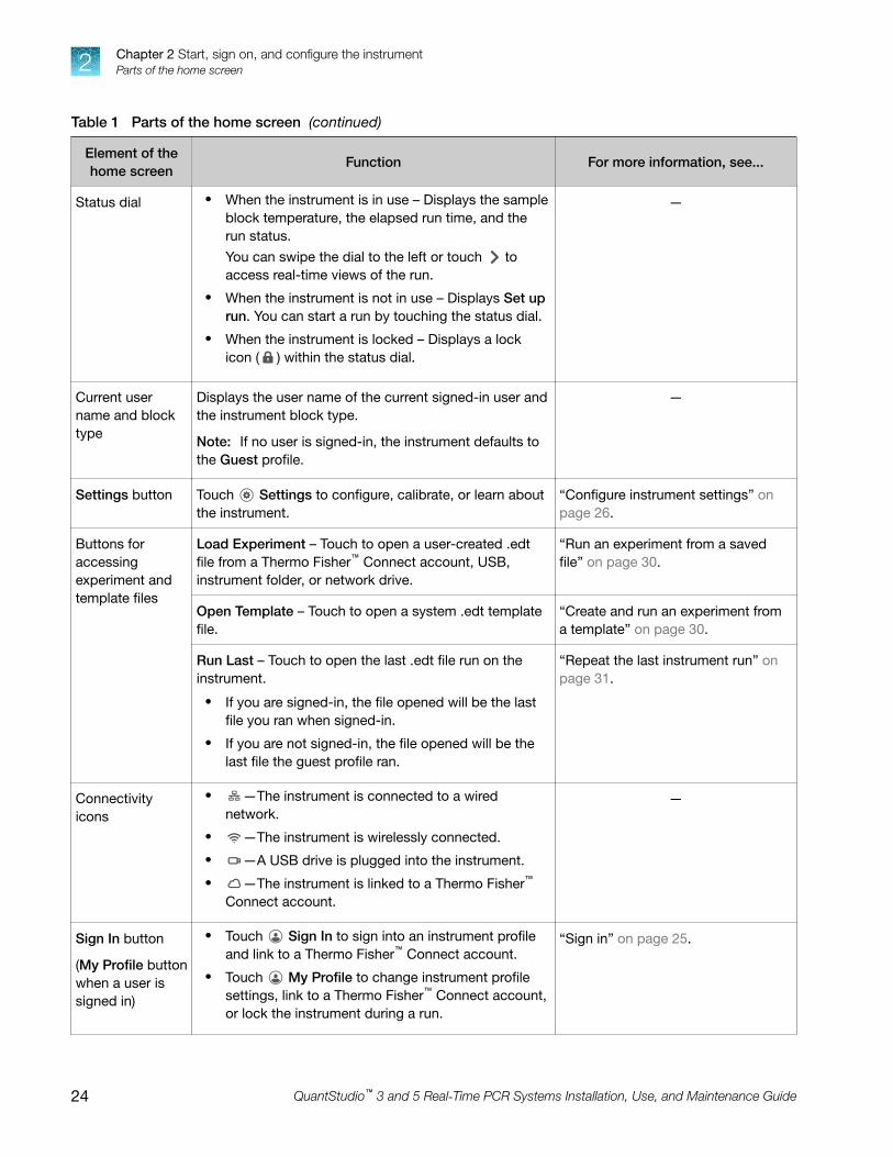
Table 1 Parts of the home screen (continued)
Element of thehome screen
Function For more information, see...
Status dial • When the instrument is in use – Displays the sampleblock temperature, the elapsed run time, and therun status.You can swipe the dial to the left or touch toaccess real-time views of the run.
• When the instrument is not in use – Displays Set uprun. You can start a run by touching the status dial.
• When the instrument is locked – Displays a lockicon ( ) within the status dial.
—
Current username and blocktype
Displays the user name of the current signed-in user andthe instrument block type.
Note: If no user is signed-in, the instrument defaults tothe Guest profile.
—
Settings button Touch Settings to configure, calibrate, or learn aboutthe instrument.
“Configure instrument settings” onpage 26.
Buttons foraccessingexperiment andtemplate files
Load Experiment – Touch to open a user-created .edtfile from a Thermo Fisher™ Connect account, USB,instrument folder, or network drive.
“Run an experiment from a savedfile” on page 30.
Open Template – Touch to open a system .edt templatefile.
“Create and run an experiment froma template” on page 30.
Run Last – Touch to open the last .edt file run on theinstrument.
• If you are signed-in, the file opened will be the lastfile you ran when signed-in.
• If you are not signed-in, the file opened will be thelast file the guest profile ran.
“Repeat the last instrument run” onpage 31.
Connectivityicons
• —The instrument is connected to a wirednetwork.
• —The instrument is wirelessly connected.
• —A USB drive is plugged into the instrument.
• —The instrument is linked to a Thermo Fisher™
Connect account.
—
Sign In button
(My Profile buttonwhen a user issigned in)
• Touch Sign In to sign into an instrument profileand link to a Thermo Fisher™ Connect account.
• Touch My Profile to change instrument profilesettings, link to a Thermo Fisher™ Connect account,or lock the instrument during a run.
“Sign in” on page 25.
Chapter 2 Start, sign on, and configure the instrumentParts of the home screen2
24 QuantStudio™ 3 and 5 Real‑Time PCR Systems Installation, Use, and Maintenance Guide

Use the instrument without signing inIf the instrument is configured by an Administrator to allow guest access ( Settings4ManageUsers4Sign In Required set to off), you can use the instrument without signing in.
The following limits are in place if you do not sign in to the instrument:
• All actions are recorded to Guest user profile.
• You have access only to the Public folder for selecting and storing experiments.
• You cannot transfer data to Thermo Fisher™ Connect (only to USB or network drive).
Create a new instrument profile1. In the home screen, touch Sign In, then touch Get Started.
2. Touch Name, enter a username, then touch Done.
3. Touch PIN Code, enter a four-digit numerical password, then touch Enter.
Note: Touch the Show PIN checkbox to switch PIN display on or off.
4. Touch Confirm PIN, then repeat step 2.
5. Touch Create profile.
6. Sign in to the profile you just created.
See “Sign in” on page 25.
Note: To enable access to Thermo Fisher™ Connect, see “Link an instrument profile to Thermo Fisher™
Connect” on page 77.
Sign inCreate an instrument profile before signing into the instrument. See “Create a new instrument profile”on page 25.
Note: An instrument profile is a user account specifically for the instrument. It is not related to anyother user account for the system or software.
1. In the home screen, touch Sign In.
2. Touch Sign In, then select your username.
3. Enter your PIN, then touch Enter.
Note: To enable access to Thermo Fisher™ Connect, see “Link an instrument profile to Thermo Fisher™
Connect” on page 77.
Chapter 2 Start, sign on, and configure the instrumentUse the instrument without signing in 2
QuantStudio™ 3 and 5 Real‑Time PCR Systems Installation, Use, and Maintenance Guide 25

Sign out1. In the home screen, touch My Profile.
2. Touch Sign Out.
Configure instrument settingsTouch Settings in the home screen to configure settings as needed.
Touch for step-by-step instructions on configuring settings.
Options Description
Instrument Settings
Instrument Name
(Administrator only)
Instrument name. If connected to a network, the instrument name must be unique.
(Optional) Add an avatar image for the instrument (.jpg, .png, or .gif) from a USB.
Sleep Mode Enable the instrument to enter a standby mode after a set length of inactivity.
Heated Cover Temperature Set the temperature of the heated cover for instrument operation and standby mode.
Enable heated cover to automatically turn off during standby mode.
Network Drive Specify a default network location for the signed-in user.
Insert Plate Reminder Enable a reminder to insert a plate before starting a run from the instrument.
OEM Connection Only
(Administrator only)
Required for API access to the instrument. When enabled, the desktop cannotconnect to the instrument.
API access to the instrument is exclusive to authorized OEM partners.
Cloud Region
(Administrator only)
Specify the regional server location to access Thermo Fisher™ Connect.
Note: Once you set a region for the cloud platform, restore factory defaults to changethe region.
Chapter 2 Start, sign on, and configure the instrumentSign out2
26 QuantStudio™ 3 and 5 Real‑Time PCR Systems Installation, Use, and Maintenance Guide

Options Description
Date/Time Set time zone and date and time formats.
Network Connection Set wired or wireless network connection for the instrument.
Restore Factory Defaults Restore the instrument to the factory settings.
IMPORTANT! Back up the instrument before restoring factory defaults (see “Backupor restore the instrument” on page 67).
Note: When you restore an instrument to its factory defaults:
· User profiles and files stored on the instrument are deleted, including all user-created .edt and .eds files and any custom dye and custom melt calibrations.
· System templates and factory calibrations remain on the instrument.
SAE Mode
(Administrator only)
(QuantStudio™ 5 Instrumentonly)
When enabled the following items apply:
• The home screen displays SAE mode.
• Runs must be started from the desktop software. The instrument locks outaccess to load experiments, open templates, repeat the last run, start a run,change the instrument name, and change the date/time.
• Only an administrator can perform calibrations.
• A user can monitor a run and view the method from the instrument touchscreen.
About Instrument
About Instrument Displays the instrument Model Name, Block Serial Number, and Firmware Version.
License Agreement Displays the End User Software License Agreement and the Limited Product Warranty.You can export the License Agreement to a USB drive.
Notifications
— Enable home screen notifications of instrument errors and software updates. Thisfunction is not related to the Notifications function in the cloud software.
The number of new, unviewed notifications displays over Settings in the home screen.
Maintenance and Service
Software Update
(Administrator only)
Update the instrument software.
Monitoring
(Administrator only)
Enable:
• Remote Monitoring Service to automatically send critical device statistics toThermo Fisher Scientific (does not monitor or send data).
• Thermo Fisher Scientific Cloud Monitor to allow real-time monitoring ofinstrument runs from a Cloud account.
Instrument Statistics Displays instrument usage information: Block Cycle Count and LED Life.
Chapter 2 Start, sign on, and configure the instrumentConfigure instrument settings 2
QuantStudio™ 3 and 5 Real‑Time PCR Systems Installation, Use, and Maintenance Guide 27

Options Description
Calibrations • Perform calibrations– ROI and Uniformity
– Dye
– Custom (including Background calibration)
• View calibration history and set calibration reminders in History and Reminders
RNase P Verification Perform instrument verification using an RNase P plate.
Self Verification Test Check the instrument hardware functions.
Log View and export Instrument Log.
Backup / Restore • Backup Instrument
• Restore a Backup (Administrator only)
Ship Prep Mode Place the instrument in a safe state for shipping, moving, or long-term storage.
Run History
— Displays the experiments run on the instrument and whether the data was transferred.
Note: Experiments run while a user is signed-in can only be viewed or transferred bythat user or an administrator.
Touch an experiment to view experiment run details and to transfer or delete .eds file.
Manage Users
Sign In Required
(Administrator only)
Enable the restriction of instrument use to only signed-in users (disables Guest profileuse).
Sign Out Timer
(Administrator only)
Set the duration of inactivity before a user is automatically signed out.
Manage Profiles
(Administrator only)
• Instrument
• Cloud
• All Profiles
Displays the profile information for the instrument and the associated Thermo Fisher™
Connect cloud-based account.
Chapter 2 Start, sign on, and configure the instrumentConfigure instrument settings2
28 QuantStudio™ 3 and 5 Real‑Time PCR Systems Installation, Use, and Maintenance Guide
Create and run experiments on theinstrument
■ Workflow . . . . . . . . . . . . . . . . . . . . . . . . . . . . . . . . . . . . . . . . . . . . . . . . . . . . . . . . . . . . . . . . . . . . . . . . . . . . 29
■ Options for running an experiment . . . . . . . . . . . . . . . . . . . . . . . . . . . . . . . . . . . . . . . . . . . . . . . . . . . . . . 30
■ Edit an experiment before starting a run . . . . . . . . . . . . . . . . . . . . . . . . . . . . . . . . . . . . . . . . . . . . . . . . . 32
■ Load and unload the plate . . . . . . . . . . . . . . . . . . . . . . . . . . . . . . . . . . . . . . . . . . . . . . . . . . . . . . . . . . . . 37
■ View, pause, or stop a run . . . . . . . . . . . . . . . . . . . . . . . . . . . . . . . . . . . . . . . . . . . . . . . . . . . . . . . . . . . . . 40
■ Transfer, view, or manage files and results . . . . . . . . . . . . . . . . . . . . . . . . . . . . . . . . . . . . . . . . . . . . . . . 41
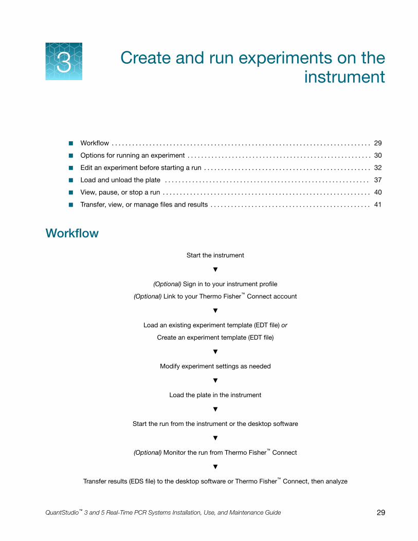
Workflow
Start the instrument
▼
(Optional) Sign in to your instrument profile
(Optional) Link to your Thermo Fisher™ Connect account
▼
Load an existing experiment template (EDT file) or
Create an experiment template (EDT file)
▼
Modify experiment settings as needed
▼
Load the plate in the instrument
▼
Start the run from the instrument or the desktop software
▼
(Optional) Monitor the run from Thermo Fisher™ Connect
▼
Transfer results (EDS file) to the desktop software or Thermo Fisher™ Connect, then analyze
3
QuantStudio™ 3 and 5 Real‑Time PCR Systems Installation, Use, and Maintenance Guide 29

Options for running an experiment
Create and run an experiment from a template
In the home screen:
1. Touch Open Template.
2. (Optional) Touch a category in the left column.
3. Touch the file name.
4. (Optional) Enter or edit template properties, including Run File Name (EDS file name), PlateBarcode, Reagent Information, and Data Destination (see “Enter or edit template properties”).
5. (Optional) Edit the run method (see “Edit the run method” on page 33).
• Add, remove, or edit a step, stage, melt curve, or data collection point.
• Adjust the heated cover temperature, sample volume, or number of cycles.
• Configure VeriFlex™ Zones, ramp rate, and pause settings.
6. (Optional) Define plate wells with sample names and view Well ID, Targets, or Dyes (see “Define,assign, and view well details”).
7. Load a plate into the instrument (see “Load and unload the plate” on page 37).
8. Touch Start Run.
When prompted, confirm that you inserted a plate.
Note: To disable this reminder, select Do not show again or select Settings4Insert PlateReminder in the home screen.
Run an experiment from a saved file
In the home screen:
1. Touch Load Experiment.
2. Touch the appropriate icon to navigate to your file location.
• For files saved to the guest profile, touch
My Instrument4Public.
• For pre and post read files, touch
My Instrument4Post Read.
3. Touch the file name.
4. (Optional) “Manage templates (EDT files)” in either USB or
My Instrument.
5. (Optional) Enter or edit template properties, including Run File Name (EDS file name), PlateBarcode, Reagent Information, and Data Destination (see “Enter or edit template properties”).
Chapter 3 Create and run experiments on the instrumentOptions for running an experiment3
30 QuantStudio™ 3 and 5 Real‑Time PCR Systems Installation, Use, and Maintenance Guide

6. (Optional) Edit the run method (see “Edit the run method” on page 33).
• Add, remove, or edit a step, stage, melt curve, or data collection point.
• Adjust the heated cover temperature, sample volume, or number of cycles.
• Configure VeriFlex™ Zones, ramp rate, and pause settings.
7. (Optional) Define plate wells with sample names and view Well ID, Targets, or Dyes (see “Define,assign, and view well details”).
8. Load a plate into the instrument (see “Load and unload the plate” on page 37).
9. Touch Start Run.
When prompted, confirm that you inserted a plate.
Note: To disable this reminder, select Do not show again or select Settings4Insert PlateReminder in the home screen.
Repeat the last instrument run
This feature applies only to runs started from the instrument and is not available for runs started fromthe desktop software. If you are signed-in, this feature applies to the last run from your instrumentprofile.
In the home screen:
1. Touch Run Last.
2. (Optional) Enter or edit template properties, including Run File Name (EDS file name), PlateBarcode, Reagent Information, and Data Destination (see “Enter or edit template properties”).
3. (Optional) Edit the run method (see “Edit the run method” on page 33).
• Add, remove, or edit a step, stage, melt curve, or data collection point.
• Adjust the heated cover temperature, sample volume, or number of cycles.
• Configure VeriFlex™ Zones, ramp rate, and pause settings.
4. (Optional) Define plate wells with sample names and view Well ID, Targets, or Dyes (see “Define,assign, and view well details”).
5. Load a plate into the instrument (see “Load and unload the plate” on page 37).
6. Touch Start Run.
When prompted, confirm that you inserted a plate.
Note: To disable this reminder, select Do not show again or select Settings4Insert PlateReminder in the home screen.
Chapter 3 Create and run experiments on the instrumentOptions for running an experiment 3
QuantStudio™ 3 and 5 Real‑Time PCR Systems Installation, Use, and Maintenance Guide 31

Edit an experiment before starting a run
Enter or edit template properties
Access a template (EDT file). For more information, see the following sections:
• “Create and run an experiment from a template” on page 30.
• “Run an experiment from a saved file” on page 30.
• “Repeat the last instrument run” on page 31.
In the Properties screen, touch Edit to enter or edit template properties.
• Edit the file name for the EDS file for the run.
a. Touch the Run File Name field.
b. Enter the name for the EDS file, then touch Done.
• Enter a plate barcode.
a. Touch the Plate Barcode field.
b. Enter or scan the plate barcode, then touch Done.
• Record reagents and their expiration dates.
a. Touch Reagent Information.
b. Touch Add, or touch an existing reagent, then touch Edit or Delete.
c. Touch the Name, Type, Lot #, Reagent Barcode, Part #, or Expiration Date field to enterindividual reagent information.
d. Touch Done.
• Automatically transfer run data (EDS file) when an instrument run ends.
a. Touch Data Destination.
b. Touch the appropriate icon to select a data destination.
c. Under the desired data destination, select Automatically transfer experiment.
d. Touch Done.
• Enter a comment.
a. Touch Comments.
b. Enter text, then touch Done.
Chapter 3 Create and run experiments on the instrumentEdit an experiment before starting a run3
32 QuantStudio™ 3 and 5 Real‑Time PCR Systems Installation, Use, and Maintenance Guide

Scan a barcode using the optional barcode scanner
The instrument is compatible with an optional Handheld Barcode Scanner (Cat. No. 4488442,purchased separately). The barcode scanner reads Code 128 (alphanumeric), which supports128 ASCII character barcodes.
1. Click the Barcode field.
2. Hold the scanner 20–30 cm away from a plate or container label and aim at the center of thebarcode, then press the trigger.
3. Slowly move the scanning beam across the barcode until the scanner emits a high-pitched tone.
When the scanner scans a barcode, it automatically transmits the following information:
• Transmits the alphanumeric equivalent of the barcode to the barcode field.
• Transmits other reagent information (Lot #, Part #, Expiration Date, etc.)
For more information about the hand-held barcode scanner, see the user documentation provided withthe barcode scanner.
Edit the run method
Access a template (EDT file):
• “Create and run an experiment from a template” on page 30.
• “Run an experiment from a saved file” on page 30.
• “Repeat the last instrument run” on page 31.
For an overview of the method as it is graphically represented on the touchscreen, see “Methodelements” on page 34.
In the Method screen:
1. Touch Edit.
2. Touch a field, enter changes, then touch Enter.
Note: Touch–drag to quickly increase or decrease a step temperature.
3. Touch Manage Steps to add or remove a step, stage, melt curve, or data collection point.
Note: The Manage Steps screen also provides access to configuring VeriFlex™ Zones, RampRates, and Add Pause settings (see “Configure VeriFlex™ Zones, ramp rates, and pause settings”on page 35).
Chapter 3 Create and run experiments on the instrumentEdit an experiment before starting a run 3
QuantStudio™ 3 and 5 Real‑Time PCR Systems Installation, Use, and Maintenance Guide 33

Method elements
2 3
1
4
5
9
8
7
6
1 Method tab
2 Heated cover temperature
3 Reaction volume
4 Stage of thermal protocol
5 Step within a stage
6 Number of cycles for the stage
7 Temperature for the step
8 Hold time for the step
9 Data collection point
Manage steps, stages, melt curves, and data collection points
Add or remove a step, stage, melt curve, or data collection point using the Manage Steps option.You can also configure ramp rates and pause settings from the Manage Steps screen (see “ConfigureVeriFlex™ Zones, ramp rates, and pause settings” on page 35).
• In the Method screen, touch Edit4Manage Steps.
Option Procedure
Add a step
1. Touch Add/Remove steps4Add steps.
2. Touch on the left or right border of a step to add a step before orafter the step, respectively.
3. Enter parameters for the new step, then touch Enter.
4. Touch Done.
Remove a step1. Touch Add/Remove steps4Remove steps.
2. Touch on the step to be removed, then touch Done.
Chapter 3 Create and run experiments on the instrumentEdit an experiment before starting a run3
34 QuantStudio™ 3 and 5 Real‑Time PCR Systems Installation, Use, and Maintenance Guide

(continued)
Option Procedure
Add a stage
1. Touch Add/Remove stages4Add stages.
2. Touch on the left or right border of a stage to add a stage before orafter the stage, respectively.
3. Edit parameters of the new stage in the Method screen. See “Edit therun method” on page 33.
4. Touch Done.
Remove a stage1. Touch Add/Remove stages4Remove stages.
2. Touch on the stage to be removed, then touch Done.
Add a melt curve
1. Touch Melt curves4Add melt curve.
2. Touch on the left or right border of a step to add a melt curve beforeor after the step, respectively.
3. Select Continuous or Step and hold.
4. Touch melt curve parameters to edit, then touch Done.
5. Touch Done.
Note: Depending on the experiment type, there can be restrictions on theaddition or placement of melt curves.
Remove a melt curve1. Touch Remove melt curve.
2. Touch on the melt curve to be removed, then touch Done.
Add or remove datacollection points
1. Touch Data collection location.
2. Touch to switch data collection on or off.
Configure VeriFlex™ Zones, ramp rates, and pause settings
In the Method screen, touch Edit4Manage Steps4Advanced Options.
• To use VeriFlex™ Zones (96‑well blocks only):
a. Touch VeriFlex™ Zones.
b. Touch on the step to apply VeriFlex™ Zones.
c. Touch each zone to edit the temperature, then touch Enter.The background colors of the VeriFlex™ Zones change with the temperature edit. Zones withhigher temperatures display a background brighter than those with lower temperatures.
d. (Optional) Apply additional VeriFlex™ Zones.
e. Touch Done.
• To edit Ramp Rates:
a. Touch Ramp Rates.
b. Touch the ramp rates fields.
Chapter 3 Create and run experiments on the instrumentEdit an experiment before starting a run 3
QuantStudio™ 3 and 5 Real‑Time PCR Systems Installation, Use, and Maintenance Guide 35

c. Touch Enter.
d. (Optional) Edit additional steps, then touch Done.
• To add a pause into the method:
a. Touch Add Pause.
b. Touch in a stage.
c. Enter the pause temperature, and the cycle after which the pause will occur.
d. Touch Enter.The pause is represented by a P in the corner of the stage.
e. Touch Done.
Define, assign, and view well details
1. Access a template (EDT file). For more information, see the following sections.
• “Create and run an experiment from a template” on page 30.
• “Run an experiment from a saved file” on page 30.
• “Repeat the last instrument run” on page 31.
2. In the Plate screen, define, assign, and view well details.
Option Procedure
Define and assign samples in theplate layout view
1. Touch .
2. Touch Manage or touch an individual well.
3. Touch the Samples subtab.
4. Select one or more wells, then touch Edit.
5. Enter sample names for the selected wells, then touch Done.
Define and assign samples in thewell table view
1. Touch .
2. Touch Edit to edit sample names for individual wells.
3. Touch a sample name field, enter a new name, then touchDone.
View target information 1. Touch .
2. Touch Manage or touch an individual well.
3. Touch the Targets subtab.
4. Touch Details to view target information, then touch Done.
3. Touch Done to return to the Plate tab.
Chapter 3 Create and run experiments on the instrumentEdit an experiment before starting a run3
36 QuantStudio™ 3 and 5 Real‑Time PCR Systems Installation, Use, and Maintenance Guide

Load and unload the plateIf a compression pad is not used, see “Load and unload a plate in the instrument” on page 37.
A compression pad is needed for some applications with a 96-well 0.2-mL MicroAmp plate.
See your product documentation to confirm if the use of a compression pad is required.
To load and unload the plate, see “Load and unload a plate in the instrument with a compression pad”on page 38.
Load and unload a plate in the instrument
CAUTION! Use flat caps for 0.2-mL tubes and 0.1-mL tubes. Rounded caps can damage the heatedcover.
1. Load the plate.
a. Touch to eject the instrument drawer.
b. Load the plate onto the plate adaptor so that the following criteria are met.
• Position well A1 of the plate in the top-left corner of the plate adapter.
• Ensure that the barcode faces the front of the instrument.
IMPORTANT! The instrument should be used by trained operators who have been warned ofthe moving parts hazard.
Note: (For 96-well 0.2-mL blocks only) Do not remove the black plate adapter before loadinga plate or tube strips. If used, tube strips can fit loosely in the adapter, but the heated coverwill apply the appropriate pressure to seat the tube strips securely in the adapter.
Note: The 384-well and 96-well Fast (0.1-mL) block configurations do not require a plateadapter.
c. Touch to close the instrument drawer.
Chapter 3 Create and run experiments on the instrumentLoad and unload the plate 3
QuantStudio™ 3 and 5 Real‑Time PCR Systems Installation, Use, and Maintenance Guide 37

2. When the run ends, unload the plate.
a. Touch to eject the instrument drawer.
b. Remove the plate.
c. Touch to close the instrument drawer.
CAUTION! PHYSICAL INJURY HAZARD. During instrument operation, the plate temperaturecan reach 100°C. Allow it to cool to room temperature before handling.
Note: If the instrument does not eject the plate, contact Support.
Load and unload a plate in the instrument with a compression pad
Some applications use a compression pad for a 96-well 0.2-mL MicroAmp plate.
1. Load the plate.
a. Touch to eject the instrument drawer.
b. Load the plate onto the plate adaptor so that the following criteria are met.
• Position well A1 of the plate in the top-left corner of the plate adapter.
• Ensure that the barcode faces the front of the instrument.
IMPORTANT! The instrument should be used by trained operators who have been warned ofthe moving parts hazard.
Note: (For 96-well 0.2-mL blocks only) Do not remove the black plate adapter before loadinga plate or tube strips. If used, tube strips can fit loosely in the adapter, but the heated coverwill apply the appropriate pressure to seat the tube strips securely in the adapter.
Chapter 3 Create and run experiments on the instrumentLoad and unload the plate3
38 QuantStudio™ 3 and 5 Real‑Time PCR Systems Installation, Use, and Maintenance Guide

c. Before loading the plate in the drawer, place the MicroAmp™ Optical Film Compression Padwith the gray side down on the surface of the plate to ensure a proper seal between theinstrument and the adhesive film.
IMPORTANT! Be careful to place the compression pad with the brown side up and thegray side down, centered on top of the plate. Ensure that the compression pad is free fromwrinkles and signs of deterioration prior to use.
d. Touch to close the instrument drawer.
2. When the run ends, unload the plate.
a. Touch to eject the instrument drawer.
b. Remove the plate.
c. Touch to close the instrument drawer.
d. Remove the MicroAmp™ Optical Film Compression Pad from the plate and store it inside thepack.
IMPORTANT!
· If the compression pad becomes stuck inside the instrument, call service to clean theheated cover.
· Between each use, place the pad back in the pouch so that it does not dry out.
· Each compression pad may be used up to 20 times before discarding. Do not use morethan 20 times.
CAUTION! PHYSICAL INJURY HAZARD. During instrument operation, the plate temperaturecan reach 100°C. Allow it to cool to room temperature before handling.
Note: If the instrument does not eject the plate, contact Support.
Chapter 3 Create and run experiments on the instrumentLoad and unload the plate 3
QuantStudio™ 3 and 5 Real‑Time PCR Systems Installation, Use, and Maintenance Guide 39

View, pause, or stop a runDo any of the following actions during an instrument run.
• View real-time data and plots (see “View real-time data and plots on the instrument touchscreen”on page 40).
• Adjust the display of real-time plots (see “Adjust the display of real-time plots on the instrumenttouchscreen” on page 41).
– Touch or swipe left once to view real‑time run method information or to edit the number ofcycles.
– Touch or swipe left twice to view real‑time data and plots.
• Pause or stop an instrument run (see “Pause or stop an instrument run” on page 40).
View real-time data and plots on the instrument touchscreen
1. In the instrument home screen, during an instrument run, touch or swipe left twice.
2. Touch Well details.
3. Touch Samples, Targets, or Tasks to select a graphical representation of each selection.
4. Touch Close to return to the home screen.
Pause or stop an instrument run
In the home screen, during an instrument run:
1. Touch or swipe left once to view real‑time run method information.
2. Stop or pause the run.
• Touch Stop Run.
• Touch Pause, then enter a pause temperature.
CAUTION! PHYSICAL INJURY HAZARD. During instrument operation, the plate temperaturecan reach 100°C. If you want to access the plate during a run pause, enter room temperature asthe pause temperature and allow the plate to cool to room temperature before handling.
3. (Optional) After pausing a run, touch Edit to change the number of cycles.
Chapter 3 Create and run experiments on the instrumentView, pause, or stop a run3
40 QuantStudio™ 3 and 5 Real‑Time PCR Systems Installation, Use, and Maintenance Guide

Adjust the display of real-time plots on the instrument touchscreen
1. In the instrument home screen, during an instrument run, touch or swipe left twice to viewreal-time data and plots.
2. Touch Zoom.
3. Touch or to zoom in or out.
4. Touch the arrows to pan left, right, up, or down on the graph.
5. Touch Close to return to the default view.
Lock the touchscreen during a run
After you have started a run, you can lock the touchscreen so that other users cannot interfere withinstrument operation.
Note: You must be signed-in to use this feature.
1. Lock the touchscreen.
a. In the home screen, touch My Profile.
b. Touch Lock Screen, then touch Lock.
2. Unlock the touchscreen.
a. Touch anywhere on the touchscreen.
b. Touch the PIN Code field, then enter your PIN.
Note: The touchscreen automatically unlocks when the run is complete.
Transfer, view, or manage files and results
Transfer EDS files from the instrument home screen
1. In the home screen, when a run ends, touch Transfer File.
2. Select the data destination for the EDS file.
3. Navigate to and select a folder.
4. Touch OK.
5. Touch Transfer.
Note: Touch Settings4Run History to transfer EDS files at any time.
Chapter 3 Create and run experiments on the instrumentTransfer, view, or manage files and results 3
QuantStudio™ 3 and 5 Real‑Time PCR Systems Installation, Use, and Maintenance Guide 41

View run history and delete or transfer files from the instrument
In the home screen, touch Settings4Run History.
• Touch an individual run record to view its details, then complete one of the following actions:– Touch Delete to delete the run record.
– Touch Transfer to export the run data.
• Touch Manage to select multiple run records for simultaneous viewing, deletion, or transfer.
Note:
· Guests (users not signed-in) can only view guest run records.
· Users signed into their instrument profiles can also view their own run records.
· Administrators can view all run records.
Note: If the connection between the instrument and the desktop software is interrupted during the run,the instrument still completes the run. However, the run data (EDS file) must be transferred from theinstrument to the desktop software using a USB drive or a network drive.
Manage templates (EDT files)
This feature applies to templates (EDT files) on a USB or in
My Instrument. To manage runresults files (EDS files), see “Transfer EDS files from the instrument home screen” on page 41.
1. In the home screen, touch Load Experiment.
2. Touch USB or
My Instrument.
3. Touch Manage Files.
4. (Optional) Navigate through the My Instrument, Public, USB, and Post Read folders to access anEDT file. Folder availability depends on your sign-in status.
5. Touch one or more files to select for managing.
6. Delete or copy the files.
• Touch Delete Files, then confirm deletion.
• Touch Copy Files, select a file destination, then touch Paste Files.
7. Touch Done.
Chapter 3 Create and run experiments on the instrumentTransfer, view, or manage files and results3
42 QuantStudio™ 3 and 5 Real‑Time PCR Systems Installation, Use, and Maintenance Guide

Calibrate and verify instrumentperformance
■ Calibration and verification schedule . . . . . . . . . . . . . . . . . . . . . . . . . . . . . . . . . . . . . . . . . . . . . . . . . . . . 43
■ Calibration descriptions . . . . . . . . . . . . . . . . . . . . . . . . . . . . . . . . . . . . . . . . . . . . . . . . . . . . . . . . . . . . . . . 44
■ View the calibration status and set reminders . . . . . . . . . . . . . . . . . . . . . . . . . . . . . . . . . . . . . . . . . . . . 45
■ Perform ROI/uniformity, background, and dye calibrations . . . . . . . . . . . . . . . . . . . . . . . . . . . . . . . . . 46
■ Perform instrument verification using RNase P plates . . . . . . . . . . . . . . . . . . . . . . . . . . . . . . . . . . . . . 53
■ Calibrate custom dyes . . . . . . . . . . . . . . . . . . . . . . . . . . . . . . . . . . . . . . . . . . . . . . . . . . . . . . . . . . . . . . . . 59
■ Calibrate for a custom melt curve experiment . . . . . . . . . . . . . . . . . . . . . . . . . . . . . . . . . . . . . . . . . . . . 65
Calibration and verification scheduleThe instrument is factory-calibrated and does not require calibration at installation. To ensure optimalperformance, perform calibrations at the recommended frequency.
Note: After instrument installation, we recommend performing instrument verification using theprovided RNase P plate.
IMPORTANT! Perform calibrations and instrument runs under the environmental conditions thatare specified in “Environmental requirements” on page 108. Exposure to extreme temperatures canadversely affect the instrument performance and shorten the life span of the instrument components.
To set the calibration frequency for the instrument, touch Settings4Maintenance andService4Calibrations4History and Reminders4Edit4Exp interval field.
Calibration Recommended frequency
ROI/Uniformity • Every two years (recommended)
• Always perform new Background and Dye calibrations after anROI/Uniformity calibration.
Note: Performing an ROI/Uniformity calibration invalidates all other calibrations.
4
QuantStudio™ 3 and 5 Real‑Time PCR Systems Installation, Use, and Maintenance Guide 43

(continued)
Calibration Recommended frequency
Background • Every two years (recommended)
• Background calibration can also be performed, as needed:– To check for contamination (depends on usage and laboratory
conditions).
– To obtain the most accurate data for the removal of backgroundfluorescence.
Note: Performing a Background calibration does not invalidate any othercalibration.
Dye • Every two years (recommended)
• During a Dye calibration, only the dyes on the given spectral calibrationplate are calibrated.
Note: Performing a Dye calibration for a given dye plate does not invalidateany other calibration.
RNase P instrumentverification
• After installing or moving the instrument
• After performing instrument calibrations (recommended)
• As needed to confirm instrument performance
Note: To prepare custom dye plates and to perform custom calibrations, see “Calibrate custom dyes”on page 59.
Calibration descriptions
Calibration description and purpose Pass Criteria
ROI/Uniformity
• The software captures images for each optical filter.
• The software uses calibration data to map the increase in fluorescenceto the plate wells during subsequent runs and to evaluate well-to-wellconsistency of the signals.
The image for each filterdistinguishes all wells of the plate.
Each well in the image is distinct.
Background
• The software captures background images for each optical filter in theabsence of sample and reagent, and it checks that the fluorescencefrom each well is below a fluorescence threshold.
• The software uses calibration data to remove background fluorescenceduring a run.
Note: You can also run this calibration to determine if contamination isrelated to the sample block or the plate.
The plate images for all filters are freeof abnormal fluorescence.
Chapter 4 Calibrate and verify instrument performanceCalibration descriptions4
44 QuantStudio™ 3 and 5 Real‑Time PCR Systems Installation, Use, and Maintenance Guide

(continued)
Calibration description and purpose Pass Criteria
Dye
• The software extracts a spectral profile for each dye standard, thenproduces a set of spectral profiles plotted as fluorescence vs filter.
• The software uses calibration data to characterize and distinguish theindividual contribution of each dye in the total fluorescence signalscollected by the instrument.
Dye spectra peak within the samefilter as their group.
View the calibration status and set reminders
View calibration status and set reminders in the instrument
1. In the home screen, touch Settings4Maintenance and Service4Calibrations4History andReminders.
2. In the Calibration Reminders screen, view the status of each calibration type.
3. (Optional) Touch a calibration row to view the history of that specific calibration type, then touchDone.
4. Touch Edit to set the calibration reminder settings. For each calibration type:
a. Slide the control On to enable the calibration reminder.
b. Edit the Exp interval and Remind me fields.
c. Touch Save.
5. (Optional) To transfer the calibration report, touch Export then follow the directions on the screen.
6. Touch Done.
View calibration status and set reminders in Thermo Fisher™ Connect
Note: The calibration reminders feature requires a connection between the instrument and a computernetwork.
1. In Thermo Fisher™ Connect, click
for the Instrument Connect page.
2. Select any of your registered instruments.
Chapter 4 Calibrate and verify instrument performanceView the calibration status and set reminders 4
QuantStudio™ 3 and 5 Real‑Time PCR Systems Installation, Use, and Maintenance Guide 45
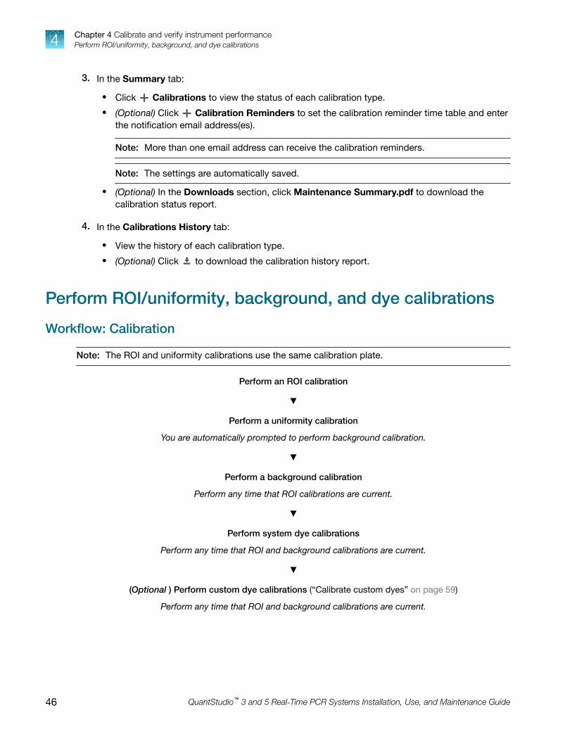
3. In the Summary tab:
• Click Calibrations to view the status of each calibration type.
• (Optional) Click Calibration Reminders to set the calibration reminder time table and enterthe notification email address(es).
Note: More than one email address can receive the calibration reminders.
Note: The settings are automatically saved.
• (Optional) In the Downloads section, click Maintenance Summary.pdf to download thecalibration status report.
4. In the Calibrations History tab:
• View the history of each calibration type.
• (Optional) Click to download the calibration history report.
Perform ROI/uniformity, background, and dye calibrations
Workflow: Calibration
Note: The ROI and uniformity calibrations use the same calibration plate.
Perform an ROI calibration
▼
Perform a uniformity calibration
You are automatically prompted to perform background calibration.
▼
Perform a background calibration
Perform any time that ROI calibrations are current.
▼
Perform system dye calibrations
Perform any time that ROI and background calibrations are current.
▼
(Optional ) Perform custom dye calibrations (“Calibrate custom dyes” on page 59)
Perform any time that ROI and background calibrations are current.
Chapter 4 Calibrate and verify instrument performancePerform ROI/uniformity, background, and dye calibrations4
46 QuantStudio™ 3 and 5 Real‑Time PCR Systems Installation, Use, and Maintenance Guide

Prepare a calibration plate
Materials required for calibration plate preparation
• Plate(s) for the calibration that you are performing:– ROI plate (the same plate is used for ROI and uniformity calibrations)
– Background calibration plate
– Dye calibration plates
Note: We recommend calibrating with all Spectral Dye Calibrations Plates available for yourblock configuration even if you are not using all the dyes in the plates.
Note: Do not discard the packaging for the calibration plates. Each calibration plate can be usedup to 3 times if the following conditions are met:
· The plate is stored in its packing sleeve at –15 to –25°C.
· The plate is used within 6 months after opening.
· The plate is used before the plate expiry date
• Centrifuge with plate adapter; buckets cleaned before use
• Powder‐free gloves
• Safety glasses
Thaw, vortex, and centrifuge a calibration plate
1. Remove the calibration plate from the freezer, then thaw the plate in its packaging. Keep platesprotected from light until you perform the calibration.
• Thaw each plate for 30 minutes.
• Use each plate within 2 hours of thawing.
IMPORTANT! Do not remove the plate from its packaging until you are ready to use it. Thefluorescent dyes in the wells of calibration plates are photosensitive. Prolonged exposure to lightcan diminish the fluorescence of the dyes.
2. While wearing powder‐free gloves, remove the calibration plate from its packaging and retain thepackaging. Do not remove the optical film.
3. Vortex the plate for 5 seconds, then centrifuge at 750–1,000 × g for 2 minutes.
4. Confirm that the liquid in each well is at the bottom of the well and free of bubbles. If it is not,centrifuge the plate again.
Chapter 4 Calibrate and verify instrument performancePerform ROI/uniformity, background, and dye calibrations 4
QuantStudio™ 3 and 5 Real‑Time PCR Systems Installation, Use, and Maintenance Guide 47

IMPORTANT! Keep the bottom of the plate clean. Fluids and other contaminants on the bottomof the plate can contaminate the sample block and cause an abnormally high background signal.
Perform calibrations
1. In the instrument home screen:
Calibration Touch
ROI/Uniformity[1] Settings4Maintenance and Service4Calibrations4ROI and Uniformity
Background[2] Settings4Maintenance andService4Calibrations4Custom4Background
Dye Settings4Maintenance and Service4Calibrations4Dye
[1] Automatically followed by Background calibration.[2] Initiate via this route if performing Background calibration only.
2. Follow the instructions on the screen to start the calibration.
Note: Dye calibration only: Select the Dye Plate to run, then touch Next.
3. Load the plate.
a. Touch to eject the instrument drawer.
Chapter 4 Calibrate and verify instrument performancePerform ROI/uniformity, background, and dye calibrations4
48 QuantStudio™ 3 and 5 Real‑Time PCR Systems Installation, Use, and Maintenance Guide

b. Load the plate onto the plate adaptor so that the following criteria are met.
• Position well A1 of the plate in the top-left corner of the plate adapter.
• Ensure that the barcode faces the front of the instrument.
IMPORTANT! The instrument should be used by trained operators who have been warned ofthe moving parts hazard.
Note: (For 96-well 0.2-mL blocks only) Do not remove the black plate adapter before loadinga plate or tube strips. If used, tube strips can fit loosely in the adapter, but the heated coverwill apply the appropriate pressure to seat the tube strips securely in the adapter.
Note: The 384-well and 96-well Fast (0.1-mL) block configurations do not require a plateadapter.
c. Touch to close the instrument drawer.
4. Touch Start.
5. When the run is complete and the screen displays Calibration Complete, touch View Results tocheck the calibration status.
Calibration status Action
Passed Touch Next to proceed to the next required calibration.
Failed See “Troubleshoot calibration failure” on page 51.
Note: You can view the calibration images only after the ROI/Uniformity and Backgroundcalibrations pass.
6. When the run ends, unload the plate.
a. Touch to eject the instrument drawer.
b. Remove the plate.
c. Touch to close the instrument drawer.
Chapter 4 Calibrate and verify instrument performancePerform ROI/uniformity, background, and dye calibrations 4
QuantStudio™ 3 and 5 Real‑Time PCR Systems Installation, Use, and Maintenance Guide 49

CAUTION! PHYSICAL INJURY HAZARD. During instrument operation, the plate temperaturecan reach 100°C. Allow it to cool to room temperature before handling.
Note: If the instrument does not eject the plate, contact Support.
7. Return the plate to its original packaging.
Note: Each calibration plate can be used up to 3 times if the following conditions are met:
· The plate is stored in its packing sleeve at –15 to –25°C.
· The plate is used within 6 months after opening.
· The plate is used before the plate expiry date
View calibration images and transfer results to USB
The instrument performs the ROI, Uniformity, and Background calibrations in sequence. You can viewthe calibration images after the Background calibration is complete.
1. In the Calibration Status screen, touch Details.
2. In the Details screen, touch a calibration type to view its images and plots.
Calibration Example results indicating successful calibration
ROI
Note: Select the desired filtercombination from the Filter Setdropdown list.
Green circles around all wells and bright well centers.
Uniformity Signals from each well following a uniform trend.
Chapter 4 Calibrate and verify instrument performancePerform ROI/uniformity, background, and dye calibrations4
50 QuantStudio™ 3 and 5 Real‑Time PCR Systems Installation, Use, and Maintenance Guide

(continued)
Calibration Example results indicating successful calibration
Background Few, if any, signals with abnormally high fluorescence.
Dye Signals from each well following a uniform trend, and each dyepeaks at the correct filter.
3. In the Calibration Status screen, touch Accept Results or Reject Results.
Accepting the results saves the calibration data to the instrument and overwrites existing data.
4. (Optional) Touch Transfer EDS to transfer the calibration data to a USB.
Troubleshoot calibration failure
Observation Possible cause Recommended action
Calibration failed The plate was improperlyprepared.
Ensure the following:
• The correct plate was used for thecalibration performed.
• The plate was properly thawed.
• The plate was properly centrifuged.
• The plate was properly sealed.
The plate is damaged orcontaminated.
Check for damage, improper plate seal, orcontamination.
Order a replacement plate. If the replacementplate fails, contact Support.
High fluorescence signal inindividual wells
Signals that exceed thelimit of normal fluorescencemay indicate fluorescentcontaminants on the plate orthe sample block.
See “Identify contamination” on page 52.
Calibration failed but plate isundamaged
The incorrect plate was usedfor calibration performed.
Use the plate that matches the calibrationperformed.
Chapter 4 Calibrate and verify instrument performancePerform ROI/uniformity, background, and dye calibrations 4
QuantStudio™ 3 and 5 Real‑Time PCR Systems Installation, Use, and Maintenance Guide 51

Observation Possible cause Recommended action
Calibration failed but plate isundamaged(continued)
The plate was improperlyprepared.
Repeat the calibration with the plate properlyprepared.
If the calibration fails again, order areplacement plate. If the replacement platefails, contact Support.
Identify contamination
Signals that exceed the limit of normal fluorescence may indicate fluorescent contaminants on thecalibration plate or the sample block. Common contaminants include ink residue from permanent pens,powder from disposable gloves, and dust.
1. View the calibration data and note the wells that failed the calibration.
2. Remove the plate from the instrument, rotate the plate 180°, then perform the calibration again.
3. Determine the location of the failed wells again as in step 1.
Position of failed wells Action
Identical The sample block is contaminated.Decontaminate the sample block (see page 68).
Reversed The plate is contaminated.Discard the plate, then perform the calibration using a newcalibration plate.
4. If the calibration fails after you decontaminate the sample block and replace the plate, contactSupport.
Create a background plate (optional)
Whenever possible, use a background plate listed in Appendix C, “Parts and materials”. These platescontain a buffer that accurately simulates the reagents used for PCR, and, therefore, produces high-quality calibration data.
If a background plate is not available, you can create one as described below.
Required materials:
• MicroAmp™ optical 96-well reaction plate
• Optical adhesive cover or optical flat caps
• Pipettor, 200‐µL (with pipette tips)
• Powder‐free gloves
• Safety glasses
• Deionized water
IMPORTANT! Wear powder-free gloves while creating the background plate.
Chapter 4 Calibrate and verify instrument performancePerform ROI/uniformity, background, and dye calibrations4
52 QuantStudio™ 3 and 5 Real‑Time PCR Systems Installation, Use, and Maintenance Guide

1. Remove a reaction plate from its box and place it on a clean, dry surface.
2. Aliquot deionized water to each well of the reaction plate.
The recommended volume for a 96-well plate is 10-20 µL.The recommended volume for 384-well plate is 5 µL.
3. Seal the plate using an optical adhesive cover or optical flat caps.
4. Use the plate for background calibration.
Perform instrument verification using RNase P platesInstruments are factory-calibrated, so calibration is not necessary for initial installation. However,perform instrument verification:
• After installation and before first use of the instrument.
• After performing instrument calibrations. (recommended)
• As needed to confirm instrument performance after calibrations, repair, preventative maintenance,or change to the system.
The instrument requires valid ROI/uniformity, background, and dye calibrations to perform instrumentverification.
Instrument verification description
Purpose Description Pass criteria
Confirms theperformance of theinstrument.
Quantifies the number of copies ofthe human RNase P gene in sampleswith known concentrations of thecorresponding DNA template.
The instrument passes performance specificationsif the following inequality is true and theinstrument successfully distinguishes betweenunknown populations A and B.
[(CtA) – 3(σCtA)] > [(CtB) + 3(σCtB)]
where:
• CtA = Average Ct of unknown population A
• σCtA = Standard deviation of unknownpopulation A
• CtB = Average Ct of unknown population B
• σCtB = Standard deviation of unknownpopulation B
RNase P instrument verification plate
The RNase P plate contains the reagents necessary for the detection and quantitation of genomiccopies of the human RNase P gene (a single-copy gene encoding the RNase moiety of the RNase Penzyme). Each well contains: PCR master mix, RNase P primers, FAM™ dye-labeled probe, and aknown concentration of human genomic DNA template.
Chapter 4 Calibrate and verify instrument performancePerform instrument verification using RNase P plates 4
QuantStudio™ 3 and 5 Real‑Time PCR Systems Installation, Use, and Maintenance Guide 53

1
42
5 76
3
8
Figure 1 96-well RNase P plate
1 Unknown A (5,000)
2 NTC (no template control)
3 STD 1,250 copies
4 STD 2,500 copies
5 STD 5,000 copies
6 STD 10,000 copies
7 STD 20,000 copies
8 Unknown B (10,000)
1
2 4
5
7
6
3
8
Figure 2 384-well RNase P plate
1 NTC (no template control)
2 STD 1,250 copies
3 STD 2,500 copies
4 STD 5,000 copies
5 STD 10,000 copies
6 STD 10,000 copies
7 Unknown A (5,000)
8 Unknown B (10,000)
Chapter 4 Calibrate and verify instrument performancePerform instrument verification using RNase P plates4
54 QuantStudio™ 3 and 5 Real‑Time PCR Systems Installation, Use, and Maintenance Guide

Performance specifications pass criteria
After the run, the software calculates average copy number values and standard deviation values.The instrument passes performance specifications if the following inequality is true and the instrumentsuccessfully distinguishes between unknown populations A and B.
[(CtA) – 3(σCtA)] > [(CtB) + 3(σCtB)]
• CtA = Average Ct of unknown population A
• σCtA = Standard deviation of unknown population A
• CtB = Average Ct of unknown population B
• σCtB = Standard deviation of unknown population B
The software automatically adjusts the threshold and omits a defined number of wells from theunknown populations to meet the performance specifications. To view any omitted wells, open theEDS file for the verification in the desktop software.
Prepare an RNase P plate
Materials required for RNase P plate preparation
• RNase P instrument verification plate
• Centrifuge with plate adapter; buckets cleaned before use
• Powder‐free gloves
• Safety glasses
Thaw, vortex, and centrifuge an RNase P plate
IMPORTANT! Expose the RNase P plate to room temperature for no more than 45 minutes, inclusiveof thawing and preparation time.
After thawing, the RNase P plate cannot be refrozen.
1. Remove the RNase P plate from the freezer, then thaw the plate in its packaging.
• Thaw the plate for approximately 5 minutes.
• Use the plate within 30 minutes of thawing.
2. Confirm that the bench, vortex, and centrifuge are clean. Before use, wipe the vortex andcentrifuge using a lint‑free tissue.
3. While wearing powder‐free gloves, remove the plate from its packaging.
4. Vortex the plate for 5 seconds, then centrifuge at 750–1,000 × g for 2 minutes.
Chapter 4 Calibrate and verify instrument performancePerform instrument verification using RNase P plates 4
QuantStudio™ 3 and 5 Real‑Time PCR Systems Installation, Use, and Maintenance Guide 55
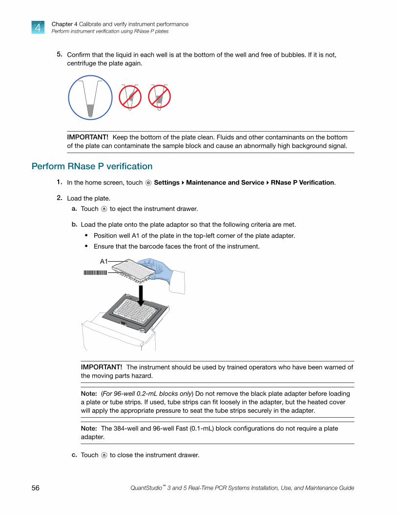
5. Confirm that the liquid in each well is at the bottom of the well and free of bubbles. If it is not,centrifuge the plate again.
IMPORTANT! Keep the bottom of the plate clean. Fluids and other contaminants on the bottomof the plate can contaminate the sample block and cause an abnormally high background signal.
Perform RNase P verification
1. In the home screen, touch Settings4Maintenance and Service4RNase P Verification.
2. Load the plate.
a. Touch to eject the instrument drawer.
b. Load the plate onto the plate adaptor so that the following criteria are met.
• Position well A1 of the plate in the top-left corner of the plate adapter.
• Ensure that the barcode faces the front of the instrument.
IMPORTANT! The instrument should be used by trained operators who have been warned ofthe moving parts hazard.
Note: (For 96-well 0.2-mL blocks only) Do not remove the black plate adapter before loadinga plate or tube strips. If used, tube strips can fit loosely in the adapter, but the heated coverwill apply the appropriate pressure to seat the tube strips securely in the adapter.
Note: The 384-well and 96-well Fast (0.1-mL) block configurations do not require a plateadapter.
c. Touch to close the instrument drawer.
Chapter 4 Calibrate and verify instrument performancePerform instrument verification using RNase P plates4
56 QuantStudio™ 3 and 5 Real‑Time PCR Systems Installation, Use, and Maintenance Guide

3. Touch Start.
4. When the run is complete and the screen displays Verification Complete, touch View Results toconfirm the status of the run.
Calibration status Action
Passed Instrument is ready for use.
Failed See “Troubleshoot verification failure” on page 57.
5. In the RNase P Verification Status screen, touch:
• Accept Results to save the results to the instrument
• Reject Results to delete the RNase P verification results
• Export Results to export the calibration results to a USB
6. When the run ends, unload the plate.
a. Touch to eject the instrument drawer.
b. Remove the plate.
c. Touch to close the instrument drawer.
CAUTION! PHYSICAL INJURY HAZARD. During instrument operation, the plate temperaturecan reach 100°C. Allow it to cool to room temperature before handling.
Note: If the instrument does not eject the plate, contact Support.
Troubleshoot verification failure
Observation Possible cause Recommended action
Verification failed The plate was improperlyprepared.
Ensure the following:
• The correct plate was used for theverification performed.
• The plate was properly thawed.
• The plate was properly centrifuged.
• The plate was properly sealed.
Open the data file for the verification in thedesktop software or Thermo Fisher™ Connectto view the flags and troubleshooting detailsfor failed wells.
The plate is damaged orcontaminated.
Check for damage, improper plate seal, orcontamination.
Order a replacement plate. If the replacementplate fails, contact Support.
Chapter 4 Calibrate and verify instrument performancePerform instrument verification using RNase P plates 4
QuantStudio™ 3 and 5 Real‑Time PCR Systems Installation, Use, and Maintenance Guide 57

Observation Possible cause Recommended action
High fluorescence signal The reaction volume is notcorrect.
Ensure that reaction volumes in the plate arecorrect and match the volume that is enteredin the Method tab.
Signals that exceed thelimit of normal fluorescencemay indicate fluorescentcontaminants on the plate orthe sample block.
Examine the bottom of the reaction plate. Ifthere is contamination, prepare a new plateand run the experiment again.
Identify the location of contamination on theplate or sample block.
1. Obtain a background plate.
2. Follow the procedures that are describedin “Identify contamination” on page 52.
Verification failed but plate isundamaged
The incorrect plate was usedfor verification.
Use the correct RNase P plate for verification.
The plate was improperlyprepared.
Repeat the verification with a new properlyprepared plate.
Note: The verification procedure is anexperiment run, so each RNase P plate canonly be used once.
Open the data file for the verification in thedesktop software or Thermo Fisher™ Connectto view the flags and troubleshooting detailsfor failed wells.
If the verification fails again, order areplacement plate. If the replacement platefails, contact Support.
Chapter 4 Calibrate and verify instrument performancePerform instrument verification using RNase P plates4
58 QuantStudio™ 3 and 5 Real‑Time PCR Systems Installation, Use, and Maintenance Guide

Calibrate custom dyes
Custom dyes overview
The instrument can run assays designed with custom dyes. Custom dyes include:
• Dyes that are not manufactured by Thermo Fisher Scientific.
• Dyes or formulations of dyes that are not system dyes for the instrument.
• For custom dye requirements, see “Custom dyes” on page 13.
Workflow: Custom dye calibration
For each custom dye, determine the optimal dye concentration. Use this concentration to prepare allsubsequent dye calibration plates.
Use a dilution series to determine an optimal custom dye concentration
Prepare a custom dye dilution plate
▼
Run the dilution plate as an experiment
▼
Determine the optimal dye concentration
▼
Calibrate the custom dye using the optimal concentration
Create a custom dye calibration plate
▼
Add a custom dye to the instrument
▼
Perform a custom dye calibration
Use a dilution series to determine an optimal custom dye concentration
Custom dye dilution guidelines
Prepare a dilution series for each custom dye.
• Target several dye concentrations within a range of 100–2,000 nM.
• Choose a 2‑ or 3‑fold difference in dilution points.
• Dispense 10–20 µL per well for 96‑well plates or 5 µL per well for 384‑well plates.
• Dilute the dye in buffer compatible with your master mix.
• (Intercalating dyes only) Add the appropriate amount of amplified PCR product to generatefluorescence.
Chapter 4 Calibrate and verify instrument performanceCalibrate custom dyes 4
QuantStudio™ 3 and 5 Real‑Time PCR Systems Installation, Use, and Maintenance Guide 59

Prepare a custom dye dilution plate
IMPORTANT! Wear powder-free gloves throughout the procedure.
1. Prepare a 2- or 3-fold dilution series of the custom dye.
2. Dispense aliquots of each dilution into the center of a reaction plate, then seal the plate.
A full plate is not needed. See the following figures for suggested replicates.
100
nM
200
nM
400
nM
800
nM
1600
nM
100
nM20
0 nM
400
nM80
0 nM
1600
nM
100
nM20
0 nM
400
nM80
0 nM
1600
nM
3. Vortex the plate for 5 seconds, then centrifuge at 750–1,000 × g for 2 minutes.
4. Confirm that the liquid in each well is at the bottom of the well and free of bubbles. If it is not,centrifuge the plate again.
IMPORTANT! Keep the bottom of the plate clean. Fluids and other contaminants on the bottomof the plate can contaminate the sample block and cause an abnormally high background signal.
Chapter 4 Calibrate and verify instrument performanceCalibrate custom dyes4
60 QuantStudio™ 3 and 5 Real‑Time PCR Systems Installation, Use, and Maintenance Guide

Run the dilution plate as an experiment
1. Load the plate into the instrument.
CAUTION! The instrument should be used by trained operators who have been warned of themoving parts hazard.
2. Set up a genotyping experiment on the instrument.
• Load an experiment created in the desktop or cloud software.a. In the home screen, touch Load Experiment.
b. Select the experiment location, then the experiment file.
• Create a new experiment on the instrument touchscreen.a. In the home screen, touch Open Template4Genotyping4Genotyping Post.
b. (Optional) In the Properties tab, edit the experiment properties.
c. In the Method tab, set the hold temperature to 60°C with a 2 minute hold and enter theappropriate reaction volume.
d. In the Plate tab, enter the dilution series information for the appropriate wells.
3. Touch Start Run.
4. When the run is complete, download the results for analysis.
5. Unload the plate from the instrument.
CAUTION! PHYSICAL INJURY HAZARD. During instrument operation, the plate temperaturecan reach 100°C. Allow it to cool to room temperature before handling.
Note: If the instrument does not eject the plate, contact Support.
Determine the optimal dye concentration
Review the dye signal data and select the dilution to use for dye calibration.
1. In the Results tab of the desktop or cloud software, select Raw Data Plot.
This plot displays the raw fluorescence signal of each optical filter, for individual wells.
Note: The Raw Data Plot cannot be viewed on the instrument touchscreen.
2. For each replicate population of dilutions, select the wells in the Plate Layout to view in the plot.
Chapter 4 Calibrate and verify instrument performanceCalibrate custom dyes 4
QuantStudio™ 3 and 5 Real‑Time PCR Systems Installation, Use, and Maintenance Guide 61

3. Examine the raw data to identify the wells yielding signals according to the ranges shown in thefollowing table.
Plate type Acceptable signal range[1]
96-well 800,000 to 3,200,000
384-well 400,000 to 2,000,000
[1] Signal range for the optical filter where the dye is brightest.
4. (Optional) Export the raw data, then calculate the average fluorescence value for eachconcentration.
5. Select the lowest (optimal) dye concentration that falls within the acceptable signal range.
Calibrate the custom dye
Create a custom dye calibration plate
IMPORTANT! Wear powder-free gloves while creating the dye plate.
Create a full plate of the custom dye diluted to the optimal concentration:
1. Dilute the custom dye to the optimal concentration in buffer.
Prepare an adequate volume, using a volume range of 10–20 µL/well for a 96‑well plate or5 µL/well for a 384-well plate.
2. Pipet the appropriate volume of the diluted custom dye to the plate wells.
3. Seal the plate.
4. Vortex the plate for 5 seconds, then centrifuge at 750–1,000 × g for 2 minutes.
5. Confirm that the liquid in each well is at the bottom of the well and free of bubbles. If it is not,centrifuge the plate again.
IMPORTANT! Keep the bottom of the plate clean. Fluids and other contaminants on the bottomof the plate can contaminate the sample block and cause an abnormally high background signal.
Chapter 4 Calibrate and verify instrument performanceCalibrate custom dyes4
62 QuantStudio™ 3 and 5 Real‑Time PCR Systems Installation, Use, and Maintenance Guide

Add a custom dye to the instrument
1. In the instrument home screen, touch Settings4Maintenance andService4Calibrations4Custom4Custom Dye.
2. Touch Add Custom Dye.
3. Enter the dye information:
Field/option Action
Custom Dye Name Enter a name for the custom dye.
IMPORTANT!
· Do not use a system dye name for a custom dye name.
· Dye names are spacing sensitive and cannot contain special characters.
Type Select:
• Reporter—The dye works in conjunction with a quencher dye to report anincrease of PCR product.
• Quencher—The dye suppresses the fluorescence of a reporter dye untilamplification of PCR product.
• Both—The dye can be used as a reporter or quencher dye.
4. Touch Save.
IMPORTANT! You must also add the custom dye to the desktop software dye library beforecreating, running, or analyzing experiments that use the custom dye. For detailed information, seethe QuantStudio™ Design and Analysis Desktop Software User Guide.
Perform a custom dye calibration
1. Load the plate into the instrument.
CAUTION! The instrument should be used by trained operators who have been warned of themoving parts hazard.
2. In the instrument home screen, touch Settings4Maintenance andService4Calibrations4Custom4Custom Dye.
3. Touch the custom dye to calibrate.
4. Review the custom dye information, (optional) make changes, then touch Update.
5. Enter the calibration temperature.
6. (Optional) Touch Reagents, then enter reagent information.
7. Touch Start.
Chapter 4 Calibrate and verify instrument performanceCalibrate custom dyes 4
QuantStudio™ 3 and 5 Real‑Time PCR Systems Installation, Use, and Maintenance Guide 63

8. When the run is complete and the screen displays Calibration Complete, touch ViewResults4Details.
9. Review the plot. Passing calibration results show uniform signals with peaks that are aligned withthe dye wavelength.
Peak filterFilter wavelength (nm)[1]
Excitation Emission
x1-m1 470 ± 15 520 ± 15
x2-m2 520 ± 10 558 ± 12
x3-m3 550 ± 10 587 ± 10
x4-m4 580 ± 10 623 ± 14
x5-m5 640 ± 10 682 ± 14
x6-m6 662 ± 10 711 ± 12
[1] The central wavelengths are the optimized wavelengths.
Note: Example dye calibration plot.The peaks for your dye may align with a different filter set.
10. Select an action depending on whether the custom dye calibration passed or failed.
Calibration status Action
Passed • Touch Accept Results or Reject Results.
Note: Accepting the results saves the calibration data to the instrumentand overwrites existing data.
• (Optional) Touch Transfer EDS to transfer the calibration data to a USB.
Failed • Perform the calibration again using a new custom dye plate.
• See “Troubleshoot calibration failure” on page 51.
11. Unload the plate from the instrument.
CAUTION! PHYSICAL INJURY HAZARD. During instrument operation, the plate temperaturecan reach 100°C. Allow it to cool to room temperature before handling.
Note: If the instrument does not eject the plate, contact Support.
Chapter 4 Calibrate and verify instrument performanceCalibrate custom dyes4
64 QuantStudio™ 3 and 5 Real‑Time PCR Systems Installation, Use, and Maintenance Guide

Calibrate for a custom melt curve experiment
Note: A custom melt calibration calibrates a custom dye and a melt calibration at the same time.
Before running the custom melt calibration:
• Ensure that all calibrations are current (touch Settings4Maintenance andService4Calibrations4History and Reminders).
• “Add a custom dye to the instrument” on page 63.
In the home screen:
1. Touch Settings4Maintenance and Service4Calibrations4Custom4Custom Melt.
2. Touch PCR + Melt or Melt only as appropriate for the kit you are using.
3. Load the plate into the instrument.
4. Select or add a dye, then select a filter set appropriate for your dye's wavelength (see filter-wavelength table below).
Note: Refer to your reagent kit documentation for dye name and wavelength information.
Peak filterFilter wavelength (nm)[1]
Excitation Emission
x1-m1 470 ± 15 520 ± 15
x2-m2 520 ± 10 558 ± 12
x3-m3 550 ± 10 587 ± 10
x4-m4 580 ± 10 623 ± 14
x5-m5 640 ± 10 682 ± 14
x6-m6 662 ± 10 711 ± 12
[1] The central wavelengths are the optimized wavelengths.
IMPORTANT! If the selected filter set does not match your reagent kit documentation, then theincorrect wavelength may be collected during a run.
5. (Optional) Touch Reagents, then enter reagent information.
6. Touch Start.
7. When the run is complete and the screen displays Calibration Complete, touch ViewResults4Details.
Chapter 4 Calibrate and verify instrument performanceCalibrate for a custom melt curve experiment 4
QuantStudio™ 3 and 5 Real‑Time PCR Systems Installation, Use, and Maintenance Guide 65

8. Review the plot. Passing calibration results show uniform signals with peaks that are aligned withthe dye wavelength.
Note: Example dye calibration plot.The peaks for your dye may align with a different filter set.
9. Select an action depending on whether the custom dye calibration passed or failed.
Calibration status Action
Passed • Touch Accept Results or Reject Results.
Note: Accepting the results saves the calibration data to the instrumentand overwrites existing data.
• (Optional) Touch Transfer EDS to transfer the calibration data to a USB.
Failed • Perform the calibration again using a new custom dye plate.
• See “Troubleshoot calibration failure” on page 51.
10. Unload the plate from the instrument.
Note: You must also add the custom dye to the desktop software dye library before creating, running,or analyzing experiments that use the custom dye. For detailed information, see the QuantStudio™
Design and Analysis Desktop Software User Guide.
Note: To perform a custom melt experiment, you can either create a Standard Curve or a Customexperiment with melt, then specify the data points per degree in the method.
Chapter 4 Calibrate and verify instrument performanceCalibrate for a custom melt curve experiment4
66 QuantStudio™ 3 and 5 Real‑Time PCR Systems Installation, Use, and Maintenance Guide

Maintain the instrument
■ Backup or restore the instrument . . . . . . . . . . . . . . . . . . . . . . . . . . . . . . . . . . . . . . . . . . . . . . . . . . . . . . . 67
■ Decontaminate the sample block . . . . . . . . . . . . . . . . . . . . . . . . . . . . . . . . . . . . . . . . . . . . . . . . . . . . . . . 68
■ Replace the instrument fuses . . . . . . . . . . . . . . . . . . . . . . . . . . . . . . . . . . . . . . . . . . . . . . . . . . . . . . . . . . 71
■ Power on or off, store, and move . . . . . . . . . . . . . . . . . . . . . . . . . . . . . . . . . . . . . . . . . . . . . . . . . . . . . . . 72
IMPORTANT! This chapter contains user maintenance procedures for the instrument. Proceduresother than those described in this document must be performed by a qualified Thermo Fisher Scientificservice representative.
Backup or restore the instrumentIn the home screen, touch Settings4Maintenance and Service4Backup/Restore.
To Action
Backup 1. Touch Backup Instrument.
2. Select a location to store the backup settings for your instrument.
3. If backing up to a USB drive, insert a USB drive into the front-panel USBport.
4. Enter a backup file name, then touch Done.
5. Select the elements to backup, or leave them all selected.
6. Touch Backup.
Restore (Administratoronly)
1. Touch Restore a Backup.
2. Select the storage location of the backup settings.
3. If restoring from a USB drive, insert a USB drive into the front-panel USBport.
4. Select the backup file, then touch Restore.
5
QuantStudio™ 3 and 5 Real‑Time PCR Systems Installation, Use, and Maintenance Guide 67
Decontaminate the sample blockPerform this procedure to eliminate fluorescent contaminants from the instrument sample block.Contamination is generally evident in failed background calibrations where one or more wellsconsistently exhibit abnormally high signals.
CAUTION! PHYSICAL INJURY HAZARD. Do not remove the instrument cover. There are nocomponents inside the instrument that you can safely service yourself. If you suspect a problem,contact Support.
CAUTION! PHYSICAL INJURY HAZARD. During instrument operation, the sample blocktemperature can reach 100°C. Allow it to cool to room temperature before handling.
CAUTION! Before using a cleaning or decontamination method other than those recommended byThermo Fisher Scientific, confirm with Thermo Fisher Scientific that the proposed method will notdamage the equipment.
Materials required
• Safety glasses
• Powder-free gloves
• Tissue, lint-free
• Cotton or nylon swabs and lint-free cloths
• Pipette (100-µL) with pipette tips
• Deionized water
• Ethanol, 95% solution
• Na-hypochlorite, (0.1% v/v) solution
Clean the sample block
CAUTION! PHYSICAL INJURY HAZARD. During instrument operation, the sample blocktemperature can reach 100°C. Allow it to cool to room temperature before handling.
IMPORTANT! Wear powder-free gloves when you perform this procedure.
IMPORTANT! Always use deionized water to rinse wells after cleaning with bleach or ethanol solution.
1. Identify the contaminated wells of the sample block (see “Identify contamination” on page 52).
2. Prepare the instrument and access the sample block:
a. Power off and unplug the instrument, then allow it to cool for 15 minutes.
Chapter 5 Maintain the instrumentDecontaminate the sample block5
68 QuantStudio™ 3 and 5 Real‑Time PCR Systems Installation, Use, and Maintenance Guide

b. Touch to eject the instrument drawer.
3. Rinse the contaminated wells with deionized water (see “Detailed procedures for cleaning thesample block” on page 70).
4. Close the drawer and test the sample block for contamination:
a. Push the instrument drawer back in to the instrument.
b. Plug in, then power on the instrument.
c. Perform a background calibration to confirm that you have eliminated the contamination.
5. If the contamination remains, clean the contaminated wells using a 95% ethanol solution:
a. Repeat step 2 – step 3.
b. Clean the contaminated wells using a 95% ethanol solution (see “Detailed procedures forcleaning the sample block” on page 70).
c. Repeat step 3 – step 4 to rinse the sample block with deionized water and to confirm that youhave eliminated the contamination.
IMPORTANT! Always use deionized water to rinse wells after cleaning with bleach or ethanolsolution.
6. If the contamination still remains, clean the contaminated wells using a Na-hypochlorite (0.1% v/v)solution:
a. Repeat step 2 – step 3.
b. Clean the contaminated wells using a Na-hypochlorite (0.1% v/v) solution (see “Detailedprocedures for cleaning the sample block” on page 70).
c. Repeat step 3 – step 4 to rinse the sample block with deionized water and to confirm that youhave eliminated the contamination.
IMPORTANT! Always use deionized water to rinse wells after cleaning with Na-hypochloriteor ethanol solution.
7. If the contamination continues to remain, contact Support.
Chapter 5 Maintain the instrumentDecontaminate the sample block 5
QuantStudio™ 3 and 5 Real‑Time PCR Systems Installation, Use, and Maintenance Guide 69
Detailed procedures for cleaning the sample block
IMPORTANT! Use these cleaning procedures only in conjunction with the complete decontaminationprocedure (see “Clean the sample block” on page 68).
• Rinse the sample block with deionized water.
a. Pipet a small volume of deionized water into each contaminated well.
b. In each well, pipet the water up and down several times to rinse the well.
c. Pipet the water to a waste beaker.
d. Use a cotton swab to scrub inside of each contaminated well.
e. Use a lint-free cloth to absorb the excess deionized water.
• Clean the sample block with 95% ethanol.
a. Pipet a small volume of 95% ethanol solution into each contaminated well.
b. In each well, pipet the solution up and down several times to rinse the well.
c. Pipet the ethanol solution to a waste beaker.
IMPORTANT! Always use deionized water to rinse wells after cleaning with bleach or ethanolsolution.
• Clean the sample block with Na-hypochlorite (0.1% v/v) solution.
a. Pipet a small volume of Na-hypochlorite (0.1% v/v) solution into each contaminated well.
b. In each well, pipet the solution up and down several times to rinse the well.
c. Pipet the bleach solution to a waste beaker.
IMPORTANT! Always use deionized water to rinse wells after cleaning with bleach or ethanolsolution.
Chapter 5 Maintain the instrumentDecontaminate the sample block5
70 QuantStudio™ 3 and 5 Real‑Time PCR Systems Installation, Use, and Maintenance Guide

Replace the instrument fuses
CAUTION! FIRE HAZARD. For continued protection against the risk of fire, replace fuses only withlisted and certified fuses of the same type and rating as those currently in the instrument.
Materials required
• Fuses (2) – 10A, Time-Lag T, 250VAC, 5 × 20mm
• Safety glasses
• Powder-free gloves
• Screwdriver, flathead
Replace the fuses
1. Power off and unplug the instrument, then allow it to cool for 15 minutes.
2. Using a flat-head screwdriver, unscrew and remove the fuse holder.
3. Remove each fuse from its fuse holder and inspect it for damage. Carbon typically coats the insideof failed fuses.
Good Failed
4. Replace each failed fuse.
Note: The voltage and amperage ratings are on the fuse holder.
5. Install the fuse holder back into the instrument.
6. Plug in, then power on the instrument.
The installation is successful if the instrument powers on.
Chapter 5 Maintain the instrumentReplace the instrument fuses 5
QuantStudio™ 3 and 5 Real‑Time PCR Systems Installation, Use, and Maintenance Guide 71

Note: Fuse failure can result from fluctuations in the supplied power to the system. To prevent furtherfailures, consider installing an electrical protective device, such as a UPS or a surge protector. If issueswith the fuse persist, contact Support.
Power on or off, store, and move
Enable Sleep Mode
1. In the home screen, touch Settings4Instrument Settings4Sleep Mode.
2. Slide the control On to enable sleep mode.
3. Touch Edit Time, then enter the time length of inactivity before the instrument enters sleep mode.
4. Touch Enter, then touch OK.
Power on the instrument
1. Touch anywhere on the touchscreen to determine if the instrument is in sleep mode. If the homescreen is displayed, the instrument is already powered on.
2. If the home screen does not display, power on theinstrument by pressing the switch on the rear panel.
If left unattended, the instrument automatically enters sleepmode (enabled by default) to conserve power.
Note: To customize the sleep mode setting, touch Settings4Instrument Settings4Sleep Mode.
Power off the instrument
The instrument operates in low-power mode when not in use. However, the instrument can be poweredoff completely so that the components use no power.
Note: To power off the instrument for >1 week, see “Prepare the instrument to store, move, or ship” onpage 73.
1. Power off the instrument using the power switch on the back of the instrument.
2. Power off the computer.
Chapter 5 Maintain the instrumentPower on or off, store, and move5
72 QuantStudio™ 3 and 5 Real‑Time PCR Systems Installation, Use, and Maintenance Guide

Prepare the instrument to store, move, or ship
In the home screen:
1. Touch Settings4Maintenance and Service4Ship Prep Mode4Next.
2. Touch to eject the instrument drawer.
3. Load the packing plate or an empty plate, then touch to close the drawer.
4. Touch Lock Block.
5. Power off the instrument using the power switch on the back of the instrument.
The instrument is now ready to store, move, or ship.
Move the instrument
CAUTION! PHYSICAL INJURY HAZARD. Do not attempt to lift the instrument or any other heavyobjects unless you have received related training. Incorrect lifting can cause painful and sometimespermanent back injury. Use proper lifting techniques when lifting or moving the instrument. At leasttwo people are required to lift it.
IMPORTANT! Moving your instrument can create subtle changes in the alignment of the instrumentoptics. Recalibrate the instrument if necessary.
• Ensure that the surface on which you place the instrument can support at least 35 kg (77 lbs).
• Ensure that the path to transport the instrument is clear of obstructions.
• At least two people are needed to lift and carry the instrument.
• Keep your spine in a good neutral position.
• Bend at the knees and lift with your legs.
• Do not lift an object and twist your torso at the same time.
• Coordinate your intentions with your assistant before lifting and carrying.
IMPORTANT! After moving the instrument, perform an RNase P instrument verification run. If the runfails, perform ROI/ uniformity, background, and dye calibrations.
Return the instrument for service
The service process requires 2 to 3 weeks.
Before returning the instrument for service, perform the following tasks.
1. Back up the instrument (see “Backup or restore the instrument” on page 67).
2. In the home screen, touch Settings4Instrument Settings4Reset Factory defaults.
3. Set the instrument to Ship Prep Mode (see “Prepare the instrument to store, move, or ship” onpage 73).
Chapter 5 Maintain the instrumentPower on or off, store, and move 5
QuantStudio™ 3 and 5 Real‑Time PCR Systems Installation, Use, and Maintenance Guide 73

To return the instrument for service, perform the following tasks.
1. Contact your local customer care center or technical support group to obtain a copy of theCertificate of Instrument Decontamination, a service notification, a service call number, andpackaging materials (if required).
2. Follow the instructions in the form to decontaminate the instrument.
IMPORTANT! The instrument must be decontaminated before packing it for shipping.
3. Complete and sign a copy of the Certificate of Instrument Decontamination.
4. Fax the Certificate of Instrument Decontamination to the customer care center.
5. Pack the instrument in the provided packaging and follow the instructions in the table below.
Prepare Include Exclude
1. Transfer any data files fromthe instrument.
2. Load an empty plate in thesample block.
3. Use the touchscreen toplace the instrument in shipmode.
Note: The empty plate andship mode protects the internalcomponents of the instrumentduring transport.
• Instrument
• Completed and signedCertificate of InstrumentDecontamination
Note: The instrument will not beaccepted for service without ahard copy of the Certificate ofInstrument Decontamination.
Any accessories, including:
• Power cord
• Ethernet cable
• USB drive
• Wireless adapter
Note: If included with theinstrument, these items will bedisposed of during service andnot returned.
6. Attach the postage provided with the Certificate of Instrument Decontamination to the box, thenship the instrument to the designated facility.
Chapter 5 Maintain the instrumentPower on or off, store, and move5
74 QuantStudio™ 3 and 5 Real‑Time PCR Systems Installation, Use, and Maintenance Guide

Configure the instrument andmanage instrument profiles
■ Initial start‑up . . . . . . . . . . . . . . . . . . . . . . . . . . . . . . . . . . . . . . . . . . . . . . . . . . . . . . . . . . . . . . . . . . . . . . . . 75
■ Manage profiles . . . . . . . . . . . . . . . . . . . . . . . . . . . . . . . . . . . . . . . . . . . . . . . . . . . . . . . . . . . . . . . . . . . . . . 76
■ Link an instrument profile to Thermo Fisher™ Connect . . . . . . . . . . . . . . . . . . . . . . . . . . . . . . . . . . . . 77
■ Enable SAE mode (Administrator only) . . . . . . . . . . . . . . . . . . . . . . . . . . . . . . . . . . . . . . . . . . . . . . . . . . 85
■ Require instrument profile sign-in (Administrator only) . . . . . . . . . . . . . . . . . . . . . . . . . . . . . . . . . . . . . 86
■ Enable remote instrument monitoring (Administrator only) . . . . . . . . . . . . . . . . . . . . . . . . . . . . . . . . . 86
■ Update instrument software (Administrator only) . . . . . . . . . . . . . . . . . . . . . . . . . . . . . . . . . . . . . . . . . . 86
■ Restore factory defaults . . . . . . . . . . . . . . . . . . . . . . . . . . . . . . . . . . . . . . . . . . . . . . . . . . . . . . . . . . . . . . . 87
■ Configure the network . . . . . . . . . . . . . . . . . . . . . . . . . . . . . . . . . . . . . . . . . . . . . . . . . . . . . . . . . . . . . . . . 87
■ Select a region for Thermo Fisher™ Connect (Administrator only) . . . . . . . . . . . . . . . . . . . . . . . . . . . 88
■ Manage the instrument name (Administrator only) . . . . . . . . . . . . . . . . . . . . . . . . . . . . . . . . . . . . . . . . 88
■ Set the date and time (Administrator only) . . . . . . . . . . . . . . . . . . . . . . . . . . . . . . . . . . . . . . . . . . . . . . . 89
■ Manage the Sign Out Timer (Administrator only) . . . . . . . . . . . . . . . . . . . . . . . . . . . . . . . . . . . . . . . . . . 89
Initial start‑upPerform these tasks during initial instrument start‑up or after you restore factory defaults (see “Restorefactory defaults” on page 87).
1. (Optional) Select one of the following options.
• Configure the instrument for either wired connection or wireless network connection (see“Configure the network” on page 87).
• Touch Neither/Decide Later.
2. (Optional) Enter an instrument name (see “Manage the instrument name (Administrator only)” onpage 88).
3. Set the date and time (see “Set the date and time (Administrator only)” on page 89).
4. Select one of the following options.
• Select a region for Thermo Fisher™ Connect.
• Touch Next to continue.
6
QuantStudio™ 3 and 5 Real‑Time PCR Systems Installation, Use, and Maintenance Guide 75
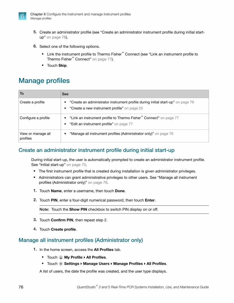
5. Create an administrator profile (see “Create an administrator instrument profile during initial start-up” on page 76).
6. Select one of the following options.
• Link the instrument profile to Thermo Fisher™ Connect (see “Link an instrument profile toThermo Fisher™ Connect” on page 77).
• Touch Skip.
Manage profiles
To See
Create a profile • “Create an administrator instrument profile during initial start-up” on page 76
• “Create a new instrument profile” on page 25
Configure a profile • “Link an instrument profile to Thermo Fisher™ Connect” on page 77
• “Edit an instrument profile” on page 77
View or manage allprofiles
• “Manage all instrument profiles (Administrator only)” on page 76
Create an administrator instrument profile during initial start-up
During initial start-up, the user is automatically prompted to create an administrator instrument profile.See “Initial start‑up” on page 75.
• The first instrument profile that is created during installation is given administrator privileges.
• Administrators can grant administrative privileges to other users. See “Manage all instrumentprofiles (Administrator only)” on page 76.
1. Touch Name, enter a username, then touch Done.
2. Touch PIN, enter a four-digit numerical password, then touch Enter.
Note: Touch the Show PIN checkbox to switch PIN display on or off.
3. Touch Confirm PIN, then repeat step 2.
4. Touch Create profile.
Manage all instrument profiles (Administrator only)
1. In the home screen, access the All Profiles tab.
• Touch My Profile4All Profiles.
• Touch Settings4Manage Users4Manage Profiles4All Profiles.
A list of users, the date the profile was created, and the user type displays.
Chapter 6 Configure the instrument and manage instrument profilesManage profiles6
76 QuantStudio™ 3 and 5 Real‑Time PCR Systems Installation, Use, and Maintenance Guide

2. Select the instrument profile to edit.
3. Edit the profile.
• To delete the profile, touch Delete profile4Delete.
• To reset the PIN, touch Reset PIN4Reset.– The user will be directed to enter a new PIN at the next sign in.
• To enable or disable administrative privileges, slide the control to Administrator or Standard,respectively.
4. Touch Done.
Edit an instrument profile
1. In the home screen, touch My Profile.
Note: Administrators can also navigate to this screen by touching Settings4ManageUsers4Manage Profiles.
2. Touch Edit.
3. Select the fields to edit, then make changes.
4. Touch Done.
Link an instrument profile to Thermo Fisher™ ConnectLinking your instrument profile to Thermo Fisher™ Connect cloud-based platform allows you to accessthe following functions:
• View an instrument status from the cloud.
• Download templates from your cloud storage to the instrument.
• Transfer run data from the instrument to your cloud storage.
To link an instrument profile to Thermo Fisher™ Connect, see the following sections:
• “Recommended order to set up profiles” on page 78
• “Overview of local instrument profiles and Thermo Fisher™ Connect profiles” on page 78
• “Thermo Fisher™ Connect instrument profile roles and functions” on page 79
• “Link the instrument to your Thermo Fisher™ Connect account” on page 80
• “Link a local profile to a Thermo Fisher™ Connect profile” on page 82
• “Unlink a Thermo Fisher™ Connect account” on page 83
• “If you link when you are signed in to the instrument” on page 84
• “Change the PIN for a Thermo Fisher™ Connect profile” on page 85
Chapter 6 Configure the instrument and manage instrument profilesLink an instrument profile to Thermo Fisher™ Connect 6
QuantStudio™ 3 and 5 Real‑Time PCR Systems Installation, Use, and Maintenance Guide 77

Recommended order to set up profiles
Task Description
Create a profile for the instrumentadministrator.
The first profile on the instrument becomes the instrumentadministrator.
See “Create an administrator instrument profile during initial start-up”on page 76.
Select a Thermo Fisher™ Connectadministrator.
A Thermo Fisher™ Connect administrator is distinct from aninstrument administrator.
The first Thermo Fisher™ Connect profile to be linked to theinstrument is automatically assigned the role of a Thermo Fisher™
Connect administrator. It is recommended that the first Connectprofile to be linked is the one that should be a Thermo Fisher™
Connect administrator.
The roles can be updated at a later time on the Thermo Fisher™
Connect platform.
Each person creates a profile.
Create a local instrument profile. Thermo Fisher™ Connect -enabledfeatures are not available.
(Optional) Link a local instrument profile to a Thermo Fisher™ Connectprofile.
Sign in with a Thermo Fisher™ Connect profile. Thermo Fisher™
Connect-enabled features are available.
Assign additional instrument administrators.Any of the profiles can be assigned the role of instrumentadministrator. The local profile must be created first or the ThermoFisher™ Connect profile must be linked first.
Overview of local instrument profiles and Thermo Fisher™ Connect profiles
• Local instrument profile– Experiment template files and data files are stored on the instrument.
– Experiment template files and data files can be transferred to the desktop software.
– Email notifications are not available.
– Separate profiles are required for each instrument if multiple instruments are used.
• Thermo Fisher™ Connect profile– Experiment template files and data files are stored on the instrument.
– Experiment template files and data files can be transferred to the Thermo Fisher™ Connectplatform or the desktop software.
– Email notifications are available.
– The same profile can be used for multiple instruments.
Chapter 6 Configure the instrument and manage instrument profilesLink an instrument profile to Thermo Fisher™ Connect6
78 QuantStudio™ 3 and 5 Real‑Time PCR Systems Installation, Use, and Maintenance Guide

Thermo Fisher™ Connect instrument profile roles and functions
The first user who links their local instrument profile to their Thermo Fisher™ Connect account isassigned a Thermo Fisher™ Connect profile with administrator role.
Instrument profile Location Functions allowed
Standard ThermoFisher™
Connect
• Create, save, open, import, and run template files
• Create and modify run settings
• View and export data files
Administrator ThermoFisher™
Connect
All the permissions of a local administrator profile, plus the followingfunctions performed in Thermo Fisher™ Connect:
• See a list of all the Thermo Fisher™ Connect profiles that are linkedto the instrument
• Assign Thermo Fisher™ Connect administrator roles to one or moreusers
• Remove a user from an instrument
• Disconnect the instrument from Thermo Fisher™ Connect
• Change the instrument name
Test the connection to the Thermo Fisher™ Connect platform
1. In the home screen, tap (Settings)4Maintenance and service4Connect services.The Connect Services screen is displayed.
2. Tap Test connection.If the connection can be established, You are able to connect to the Connect platform will bedisplayed.
Chapter 6 Configure the instrument and manage instrument profilesLink an instrument profile to Thermo Fisher™ Connect 6
QuantStudio™ 3 and 5 Real‑Time PCR Systems Installation, Use, and Maintenance Guide 79

If the connection cannot be established, Unable to connect will be displayed.
3. Tap Close.
Link the instrument to your Thermo Fisher™ Connect account
This section describes using your Thermo Fisher™ Connect account when you use the instrument forthe first time.
The first time you use your Thermo Fisher™ Connect account on an instrument, you will be prompted tocreate a four-digit numerical PIN. This PIN is to use when signing in to the instrument with your ThermoFisher™ Connect account. It will apply to all other instruments when you use your Thermo Fisher™
Connect account. This does not change the password when signing in to your Thermo Fisher™ Connectaccount on a browser.
Chapter 6 Configure the instrument and manage instrument profilesLink an instrument profile to Thermo Fisher™ Connect6
80 QuantStudio™ 3 and 5 Real‑Time PCR Systems Installation, Use, and Maintenance Guide

After the PIN is set up on the instrument, it must be changed with your Thermo Fisher™ Connectaccount on a browser, see “Create an administrator instrument profile during initial start-up” onpage 76.
The first time the instrument is used with a Thermo Fisher™ Connect account, a region must beselected.
1. In the Sign In screen, tap Get started4Create a local instrument file4Connect to yourThermo Fisher™ Connect account.
2. (Optional) Select the appropriate region.
Option Description
China For users in China
U.S. For users in any country other than China
3. Tap a connection option.
Option Action
Mobiledevices Note: Before selecting this option, install and sign in to the Thermo Fisher™ Connect
application on your mobile device.
On the instrument:
1. Tap
Mobile devices.
2. Hold the camera on your mobile device over the QR code that is displayed on thetouchscreen.
3. Tap Close.
PC A link code is displayed on the instrument.On a computer:
1. Access the Thermo Fisher™ Connect platform.
2. Click Add instrument.
3. Select QuantStudio.
4. Enter the link code.
4. (Optional) In the Enter PIN screen, tap the PIN (4 digits required) field, enter a four-digit numericalPIN, then tap Enter.
Tap the Show PIN checkbox to show or hide the PIN.
5. (Optional) Tap the Confirm PIN field, enter the four-digit numerical PIN again, then tap Enter.
6. Tap Done.
Chapter 6 Configure the instrument and manage instrument profilesLink an instrument profile to Thermo Fisher™ Connect 6
QuantStudio™ 3 and 5 Real‑Time PCR Systems Installation, Use, and Maintenance Guide 81

Link a local profile to a Thermo Fisher™ Connect profile
This section describes linking a local instrument profile to a Thermo Fisher™ Connect profile, if a localinstrument profile was created first.
The first time you use your Thermo Fisher™ Connect account on an instrument, you will be prompted tocreate a four-digit numerical PIN. This PIN is to use when signing in to the instrument with your ThermoFisher™ Connect account. It will apply to all other instruments when you use your Thermo Fisher™
Connect account. This does not change the password when signing in to your Thermo Fisher™ Connectaccount on a browser.
After the PIN is set up on the instrument, it must be changed with your Thermo Fisher™ Connectaccount on a browser, see “Change the PIN for a Thermo Fisher™ Connect profile” on page 85.
The first time the instrument is used with a Thermo Fisher™ Connect account, a region must beselected.
For a detailed description of the profile, see “If you link when you are signed in to the instrument” onpage 84.
(Optional) Test the connection, see “Test the connection to the Thermo Fisher™ Connect platform” onpage 79.
1. In the home screen, tap (Profile).The My Profile screen is displayed.
2. Tap Connect4Link Account.The Connect to Connect Platform screen is displayed.
3. (Optional) Select the appropriate region.
Option Description
China For users in China
U.S. For users in any country other than China
Chapter 6 Configure the instrument and manage instrument profilesLink an instrument profile to Thermo Fisher™ Connect6
82 QuantStudio™ 3 and 5 Real‑Time PCR Systems Installation, Use, and Maintenance Guide
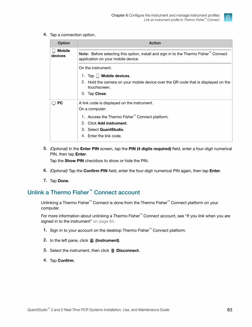
4. Tap a connection option.
Option Action
Mobiledevices Note: Before selecting this option, install and sign in to the Thermo Fisher™ Connect
application on your mobile device.
On the instrument:
1. Tap
Mobile devices.
2. Hold the camera on your mobile device over the QR code that is displayed on thetouchscreen.
3. Tap Close.
PC A link code is displayed on the instrument.On a computer:
1. Access the Thermo Fisher™ Connect platform.
2. Click Add instrument.
3. Select QuantStudio.
4. Enter the link code.
5. (Optional) In the Enter PIN screen, tap the PIN (4 digits required) field, enter a four-digit numericalPIN, then tap Enter.
Tap the Show PIN checkbox to show or hide the PIN.
6. (Optional) Tap the Confirm PIN field, enter the four-digit numerical PIN again, then tap Enter.
7. Tap Done.
Unlink a Thermo Fisher™ Connect account
Unlinking a Thermo Fisher™ Connect is done from the Thermo Fisher™ Connect platform on yourcomputer.
For more information about unlinking a Thermo Fisher™ Connect account, see “If you link when you aresigned in to the instrument” on page 84.
1. Sign in to your account on the desktop Thermo Fisher™ Connect platform.
2. In the left pane, click
(Instrument).
3. Select the instrument, then click Disconnect.
4. Tap Confirm.
Chapter 6 Configure the instrument and manage instrument profilesLink an instrument profile to Thermo Fisher™ Connect 6
QuantStudio™ 3 and 5 Real‑Time PCR Systems Installation, Use, and Maintenance Guide 83

If you link when you are signed in to the instrument
In this scenario, your local instrument profile name is created manually on the instrument before youlink. Your local instrument profile name differs from your Thermo Fisher™ Connect instrument profilename.
Phase Steps that occur
Before you link: • You enter your local instrument profile name in the Sign In screen.
• Your local instrument profile (UserABC) is displayed in the home screen of theinstrument.
• All plates and results that you create are accessible only when you are signed inwith your local instrument profile.
When you link: • You link your local instrument profile (see “Link a local profile to a Thermo Fisher™
Connect profile” on page 82).
• If this is the first time you link, a Thermo Fisher™ Connect instrumentprofile is created using the FirstNameLastInitial of the user name from yourthermofisher.com account.Example: [email protected] First name is User, Last name is Gray.Thermo Fisher™ Connect account username is User G.
• Your local instrument profile (UserABC) is linked to your Thermo Fisher™ Connectaccount ([email protected]).
• Your Thermo Fisher™ Connect instrument profile (User G.) replaces your localinstrument profile.
After you link: • Your Thermo Fisher™ Connect instrument profile (User G.) and is displayed inthe home screen of the instrument.
• Plate files and data files from your local instrument profile can be transferred toThermo Fisher™ Connect.
• New plate files and data files are saved under your Thermo Fisher™ Connectinstrument profile.
If your Thermo Fisher™
Connect account isunlinked:
• Your local instrument profile (UserABC) is displayed in the home screen of theinstrument.
• Plate files and data files that were saved under your Thermo Fisher™ Connectinstrument profile are accessible under your local instrument profile.
• Plate files and data files are saved under local instrument profile and can becopied to Thermo Fisher™ Connect (see “Manage templates (EDT files)” onpage 42 and “Transfer EDS files from the instrument home screen” on page 41).
• Your local instrument profile name (UserABC) is available for selection in the SignIn screen.
Chapter 6 Configure the instrument and manage instrument profilesLink an instrument profile to Thermo Fisher™ Connect6
84 QuantStudio™ 3 and 5 Real‑Time PCR Systems Installation, Use, and Maintenance Guide

Change the PIN for a Thermo Fisher™ Connect profile
This section describes changing a PIN for a Thermo Fisher™ Connect profile. To change a PIN for alocal instrument profile, see “Manage all instrument profiles (Administrator only)” on page 76.
1. Sign in to Thermo Fisher™ Connect on a browser.
2. Click Update PIN number.
3. In the Update PIN number dialog box, enter a new PIN, then enter the new PIN a second time toconfirm it.
4. Click Send.
The 4-digit PIN to sign in to instruments with your Thermo Fisher™ Connect profile is updated. Thischange applies to all of the instruments that you access with your Thermo Fisher™ Connect profile.
Enable SAE mode (Administrator only)Security, Audit, and e-Signature (SAE) functions are only available for the QuantStudio™ 5 System.
The SAE module works with the instrument and desktop software to record and restrict various useractivities. Audits and e-Signatures are tracked in the desktop software.
In the home screen:
1. Touch Settings4Instrument Settings4SAE Mode.
2. Slide the control On to enable SAE on the instrument.
3. Touch OK.
The following instrument functions are disabled in SAE mode.
• Start a run from the instrument.
Note: All instrument runs must be started from desktop software that has SAE functions enabled.
• Edit an instrument name.
• Edit an instrument date or time.
• Restore to factory defaults.
• Perform a software update.
Chapter 6 Configure the instrument and manage instrument profilesEnable SAE mode (Administrator only) 6
QuantStudio™ 3 and 5 Real‑Time PCR Systems Installation, Use, and Maintenance Guide 85

Require instrument profile sign-in (Administrator only)1. In the home screen, touch Settings4Manage Users4Sign In Required.
2. Slide the control On.Only signed-in users are allowed to access the instrument for any task, including access toSettings.
3. Touch Done.
Enable remote instrument monitoring (Administrator only)1. In the home screen, touch Settings4Maintenance and Service4Monitoring.
2. Configure the instrument monitoring settings.
Option Description
RemoteMonitoringService
Slide the control On to enable the Remote Monitoring Service.Enabling the Remote Monitoring Service allows the instrument to automaticallynotify Thermo Fisher Scientific support teams in real time of potential instrumentissues. The service monitors and sends general instrument data, but the servicedoes not monitor or send customer data.
Thermo Fisher™
Connect MonitorSlide the control On to enable users to access real‑time monitoring ofamplification plots from the Thermo Fisher™ Connect dashboard (cloud-basedplatform).
3. Touch OK.
Update instrument software (Administrator only)1. In the home screen, touch Settings4Maintenance and Service4Software Update.
2. Select the location of the update files.
3. When prompted, confirm your request to update the software.
Chapter 6 Configure the instrument and manage instrument profilesRequire instrument profile sign-in (Administrator only)6
86 QuantStudio™ 3 and 5 Real‑Time PCR Systems Installation, Use, and Maintenance Guide

Restore factory defaultsThis procedure can only be performed by an Administrator.
IMPORTANT! Back up the instrument before restoring factory defaults (see “Backup or restore theinstrument” on page 67).
1. In the home screen, touch Settings4Instrument Settings4Restore Factory Defaults.
2. Touch Restore Factory Defaults.
3. Power Off, then power On the instrument to apply the change.
• Instrument profiles and files stored on the instrument are deleted, including all EDS files andany custom dye calibrations.
• The most recent valid ROI/Uniformity, Background, and system dye calibrations are notdeleted.
After restoring factory defaults, perform initial start‑up tasks. See “Initial start‑up” on page 75.
Configure the network
IMPORTANT! Configure the instrument for either wired connection or wireless connection but notboth.
“Set up a wired connection” on page 87
“Set up a wireless connection” on page 88
Set up a wired connection
1. In the home screen, touch Settings4Instrument Settings4Network Connection4 Wired.
2. In the Network Configuration screen, touch a radio button to connect to a network either byDHCP or by a Static IP address.
Option Action
Automatic Touch DHCP.
Manual 1. Touch Static IP.
2. Enter the IP address for the instrument, the Subnet Mask, the Default Gateway, and(optional) the Primary DNS Server and the Secondary DNS Server.Addresses are in the form of X.X.X.X, where each X is a number from 0 to 255.
Chapter 6 Configure the instrument and manage instrument profilesRestore factory defaults 6
QuantStudio™ 3 and 5 Real‑Time PCR Systems Installation, Use, and Maintenance Guide 87

Note: Ask your system administrator if the IP address is assigned statically or dynamically. Forstatic addresses, you need to know the IP address for the instrument, the Subnet Mask, and theDefault Gateway.
3. Touch OK.
Set up a wireless connection
1. In the home screen, touch Settings4Instrument Settings4Network Connection4Wireless to display a list of the available networks.
2. Select a network or touch Join other network, enter the network password, then touch Enter.If you select Join other network, enter the network name and security type.
3. Touch Join to continue.
4. In the Network Connection Complete screen, touch Next.
5. Touch OK.
6. In the Network Configuration screen, edit the Network details or touch Done.
Select a region for Thermo Fisher™ Connect (Administratoronly)
During the initial startup, you will be automatically prompted to select a region for Thermo Fisher™
Connect. Return to the selection through Settings, if necessary.
1. In the home screen, touch Settings4Instrument Settings4Thermo Fisher Connect Region.
2. Touch a region.
The server used to store your data is located in this region.
3. Touch OK.
Manage the instrument name (Administrator only)1. In the home screen, touch Settings4Instrument Settings4Instrument Name.
2. Touch the Instrument Name field, enter an instrument name, then touch Done.
3. Touch OK.
Chapter 6 Configure the instrument and manage instrument profilesSelect a region for Thermo Fisher™ Connect (Administrator only)6
88 QuantStudio™ 3 and 5 Real‑Time PCR Systems Installation, Use, and Maintenance Guide

Set the date and time (Administrator only)1. In the home screen, touch Settings4Instrument Settings4Date/Time.
2. Select a time zone from the dropdown list.
3. Select a date format.
a. Touch Date Format, then select the preferred date format.
b. Touch Next, touch the date field, then enter the date.
c. Touch Enter, then touch Done.
4. Select a time format.
a. Touch Time Format.
b. Slide the control to select a 12‑hour or 24‑hour clock.
c. Touch Next, touch the time field, then enter the time.
d. Touch Enter, then touch Done.
5. Touch Done.
Manage the Sign Out Timer (Administrator only)
1. In the home screen, touch Settings4Manage Users4Sign Out Timer.
2. Touch the Edit Time field, then enter the desired duration of inactivity before automatic user signout.
3. Touch Enter, then touch Done.
Chapter 6 Configure the instrument and manage instrument profilesSet the date and time (Administrator only) 6
QuantStudio™ 3 and 5 Real‑Time PCR Systems Installation, Use, and Maintenance Guide 89

Install and connect the instrument toa network
■ Workflow: Install and connect to a network . . . . . . . . . . . . . . . . . . . . . . . . . . . . . . . . . . . . . . . . . . . . . . 90
■ Before you begin . . . . . . . . . . . . . . . . . . . . . . . . . . . . . . . . . . . . . . . . . . . . . . . . . . . . . . . . . . . . . . . . . . . . . 91
■ Unpack and install the instrument . . . . . . . . . . . . . . . . . . . . . . . . . . . . . . . . . . . . . . . . . . . . . . . . . . . . . . 91
■ Power on and follow the startup wizard . . . . . . . . . . . . . . . . . . . . . . . . . . . . . . . . . . . . . . . . . . . . . . . . . 92
■ Connect the computer to the instrument directly or to a LAN . . . . . . . . . . . . . . . . . . . . . . . . . . . . . . . 92
■ Instrument and computer connections . . . . . . . . . . . . . . . . . . . . . . . . . . . . . . . . . . . . . . . . . . . . . . . . . . 93
■ Download and install the desktop software . . . . . . . . . . . . . . . . . . . . . . . . . . . . . . . . . . . . . . . . . . . . . . 94
■ Networking . . . . . . . . . . . . . . . . . . . . . . . . . . . . . . . . . . . . . . . . . . . . . . . . . . . . . . . . . . . . . . . . . . . . . . . . . . 95
Workflow: Install and connect to a network
Perform all steps in “Before you begin” on page 91
▼
“Unpack and install the instrument” on page 91
▼
“Power on and follow the startup wizard” on page 92
▼
“Perform instrument verification using RNase P plates” on page 53
▼
“Connect the computer to the instrument directly or to a LAN” on page 92
A
90 QuantStudio™ 3 and 5 Real‑Time PCR Systems Installation, Use, and Maintenance Guide
Before you beginThis section provides instructions for customer installation of the computer and the instrument. Forinstallation by a field service engineer (FSE), contact Support to order a service call.
Before starting the installation, complete the following tasks:
• Determine the configuration for your instrument and obtain the network information you need (see“Networking” on page 95).
• Review site requirements (see QuantStudio™ 3 and 5 Real‑Time PCR Systems Site PreparationGuide (Pub. No. MAN0010405).
• Review instrument and computer connections (see “Instrument and computer connections” onpage 93).
Unpack and install the instrument1. Prepare the installation site as described in the QuantStudio™ 3 and 5 Real‑Time PCR Systems Site
Preparation Guide (Pub. No. MAN0010405).
2. Follow the pre-printed instructions on the instrument box to unpack the instrument, accessories,and reference documentation. Save the packing material for future use or recycle it.
The instrument box contains:
• Reference documentation: Welcome note, unpacking and set up instructions card, systemdocumentation insert
• One instrument
• Accessories: power cable, Ethernet cable, USB drive, reaction tube retainer
• Shipping plate
Note: Save the shipping plate but do not use it to operate the instrument.
If you ordered the wireless adapter, it is provided separately.
3. Place the instrument on the bench.
4. Plug the power cable into the power port on the back panel of the instrument, then plug the cableinto an electrical receptacle.
5. Connect your instrument as required by your network configuration (see “Supported options forinstrument and computer connections” on page 95 and “Instrument and computer connections”on page 93).
• Connect an Ethernet cable to the Ethernet port on the back panel of the instrument, thenconnect the cable to a computer or a networking port.or
• Connect wirelessly via the wireless adapter.
Appendix A Install and connect the instrument to a networkBefore you begin A
QuantStudio™ 3 and 5 Real‑Time PCR Systems Installation, Use, and Maintenance Guide 91

Note: Do not connect the High Power USB WiFi Module (Cat. No. A26774) to the instrument ifit is connected to a network by an Ethernet cable. Configuring the instrument for both wired andwireless connection can interfere with instrument operation.
Power on and follow the startup wizard1. Power on the instrument.
2. Follow the startup wizard through the following tasks:
• Select the language for the instrument.
• Accept the license agreement.
• Select a Wired or Wireless networking option, as needed for your configuration (see“Supported options for instrument and computer connections” on page 95).
• Configure the instrument date and time.
• Create an administrator instrument profile.
Note: You can perform any of the steps above at a later time if you do not have the informationneeded to complete the startup screens. See “Configure instrument settings” on page 26.
IMPORTANT! Before using the instrument for the first time, we recommend that you performinstrument verification using RNase P plates (see “Perform instrument verification using RNase Pplates” on page 53).
Connect the computer to the instrument directly or to aLAN
This section describes the direct wired connection of the computer to the instrument or to a LAN.
1. Connect an Ethernet cable from the instrument or a LAN to the computer.
2. Power on the computer, then log in using a Windows™ Administrator account.
3. Open the Control Panel, then open the Network and Sharing Center.
4. In the left pane of the Network and Sharing Center window, click Change Adapter Settings.
5. Right-click on Broadband Connection, then select Properties.
6. In the Networking tab, select Internet Protocol Version 4 (TCP/IPv4).
7. Click Properties.
Appendix A Install and connect the instrument to a networkPower on and follow the startup wizardA
92 QuantStudio™ 3 and 5 Real‑Time PCR Systems Installation, Use, and Maintenance Guide

8. In the Internet Protocol Version 4 (TCP/IPv4) Properties dialog box, select one of the followingoptions.
• Obtain an IP address automatically
• Use the following IP address
9. If Use the following IP address was selected, enter the IP address.
10. Close all dialog boxes by clicking OK, then re-start the computer.
Instrument and computer connections
1
7
66
5
4
2
3
Figure 3 Instrument back panel
1 USB ports
2 WiFi USB port—Connect USB wireless adapter forwireless network access (ordered separately)
3 Ethernet Port—RJ45 port for 100/1,000 Mbps Ethernetcommunication with the instrument
4 RS232 Port—For service use only
5 Fuse Cover
6 Power Switch
7 Power Port—100 to 240 VAC
Appendix A Install and connect the instrument to a networkInstrument and computer connections A
QuantStudio™ 3 and 5 Real‑Time PCR Systems Installation, Use, and Maintenance Guide 93

3
1 12
4
Figure 4 Instrument‑to‑computer connections (barcode scanner connected to the computer)
Minitower configuration
1 Detachable power supply cord compatible with local power supply receptacle.
2 Connection between the computer and the instrument.
3 Connection between the computer and the monitor, keyboard, and mouse.
4 Connection between the computer and the (optional) handheld barcode scanner.
Download and install the desktop software
Computer requirements for the desktop software
If you purchased a computer provided by Thermo Fisher Scientific, you can install the desktop softwareand use it to control the instrument.
This instrument uses QuantStudio™ Design and Analysis Software v1.5.x. QuantStudio™ Design andAnalysis Software v2.x can also be used to setup and analyze files.
Thermo Fisher Scientific does not support the use of customer-provided computers to control theinstrument.
However, if desired, you can install the desktop software on a customer-provided computer and usethe software to create templates and analyze data. Minimum requirements for a customer-providedcomputer are:
• Operating system—Windows™ 10 (64‑bit)
• Processor—Pentium® 4 or comparable
• Memory—4 GB RAM
• Hard drive—500 GB
• Monitor—1280 × 1024 resolution
Appendix A Install and connect the instrument to a networkDownload and install the desktop softwareA
94 QuantStudio™ 3 and 5 Real‑Time PCR Systems Installation, Use, and Maintenance Guide

Download the desktop software
1. Sign in to your account at thermofisher.com.
Note: If you do not have an account, create an account.
2. Go to thermofisher.com/quantstudio3-5softwaredownloads.
3. Download the software and the example files.
Install the desktop software
1. Use a Windows™ Administrator account to log in to the computer on which you are installing thedesktop software.
2. Unzip the downloaded software and example files.
3. Double-click setup.exe.
4. Follow the InstallShield Wizard prompts to install the software.
5. Accept the License Agreement.
6. Select Typical as the setup preference, then click Next.
7. If you are installing the software on a computer provided by Thermo Fisher Scientific, installthe software on the D:\ drive. If you are installing on a customer-provided computer, install thesoftware in your preferred location.
8. Click Finish.
Networking
IMPORTANT! This section provides general networking information. It does not provide adequatedetail to integrate the instrument into all possible network architectures. Because a network maycontain advanced features (such as a firewall or network domains), we recommend that you consulta network administrator before connecting the instrument to your laboratory network.
Supported options for instrument and computer connections
We support the following direct, networked (LAN– local area network), or Thermo Fisher™ Connectconfigurations. Configurations other than those listed are not recommended. Select a configuration thatmeets the needs of your laboratory's instrument, software, and workflow requirements.
IMPORTANT! Do not connect both an Ethernet cable and the Wi‑Fi module (Cat. No. A26774) tothe instrument. Configuring the instrument for both wired and wireless connection can interfere withinstrument operation.
Appendix A Install and connect the instrument to a networkNetworking A
QuantStudio™ 3 and 5 Real‑Time PCR Systems Installation, Use, and Maintenance Guide 95

Note: For detailed information about networking your instrument, see the QuantStudio™ 3 and 5Real‑Time PCR Systems IT Checklist (Pub. No. MAN0013738).
Direct configuration option
• A computer provided by Thermo Fisher Scientific with the QuantStudio™ Design and Analysis Software
• Computer‑to‑instrument connection:– Direct, wired connection between the computer and the instrument
using an Ethernet cable
IMPORTANT! A direct instrument‑to‑computer connection cannot becombined with the LAN or the Thermo Fisher™ Connect configurations.
Networked configuration option
• A computer provided by Thermo Fisher Scientific with the QuantStudio™ Design and Analysis Software
• The computer and instrument must have the same subnet mask within the same network.
• Computer‑to‑LAN connection (select an option):– Wired connection to the network using an Ethernet cable – or –
– Wireless connection to the network
LAN
LAN
• Instrument‑to‑LAN connection (select an option):– Wired connection to the network using an Ethernet cable – or –
– Wireless connection to the network using the instrument Wi‑Fi module
Thermo Fisher™ Connect configuration option
• Internet access and a computer with the Chrome™ web browser to access Thermo Fisher™ Connect
• Computer‑to‑Thermo Fisher™ Connect connection (select an option):– Wired connection to the internet using an Ethernet cable – or –
– Wireless connection to the internet LAN
• Instrument‑to‑Thermo Fisher™ Connect connection (select an option):– Wired connection to the network using an Ethernet cable – or –
– Wireless connection to the network using the instrument Wi‑Fi module
Appendix A Install and connect the instrument to a networkNetworkingA
96 QuantStudio™ 3 and 5 Real‑Time PCR Systems Installation, Use, and Maintenance Guide

Control and monitor networked instruments
When the instrument is connected to a network:
• Computers on the network that are running the desktop software can control the instrument.Networked instruments can be controlled by only one computer at a time.
• Instruments linked to Thermo Fisher™ Connect cannot be controlled remotely. However, you canperform the following functions:
– Remotely access Thermo Fisher™ Connect to create (and analyze) experiments.
– From the instrument, download the experiments and start a run.
– Monitor a run from Thermo Fisher™ Connect in real time.
Ethernet port overview
The Ethernet port of the instrument supports:
• Static IP network service with subnet mask, primary and secondary data network service (DNS),and default gateway settings, or dynamic host configuration protocol (DHCP) network service.
• mDNS/DNS for local domains.
Note: Because mDNS is limited to direct network connections, an instrument configured formDNS may not be visible to other nodes that are separated by a router, hub, or another networkdevice.
• IPv4 linknlocal (IPV4LL) in the RFC (also known as Automatic Private IP Addressing [APIPA] orInternet Protocol Automatic Configuration [IPAC]).
Note: When an instrument is set for DHCP, APIPA is automatically enabled, and the instrumentprovides an IP address when no address is supplied by the DHCP server.
Firewall ports that must be open
Ports Condition
80/443Standard ports for instrument-to-Thermo Fisher™ Connect and computer-to-Thermo Fisher™ Connect connections
mDNS, 7443 Instrument-to-computer connection
mDNS, 5353 Instrument discovery
Appendix A Install and connect the instrument to a networkNetworking A
QuantStudio™ 3 and 5 Real‑Time PCR Systems Installation, Use, and Maintenance Guide 97

Networking guidelines and best practices
• Consult a network administrator before connecting the instrument to a network.
• To enable the full functionality of the software, the computer requires a network connection.
• Open the firewall port for the instruments to be discovered. See “Firewall ports that must be open”on page 97.
• Observe the restrictions to mDNS and Autodiscovery.The instrument supports mDNS but only when the instrument and computer share a direct networkconnection and are within the same subnet. Network computers that are separated from theinstrument by a router, hub, or another network device may not be able to access the instrument byits host name.
• Confirm the uniqueness of the instrument name.– The instrument name must be unique within the subnet. The desktop software can
automatically discover instruments on the link-local network.
– The instrument does not test the uniqueness of the instrument name within the subnet when itis set.
Appendix A Install and connect the instrument to a networkNetworkingA
98 QuantStudio™ 3 and 5 Real‑Time PCR Systems Installation, Use, and Maintenance Guide

Troubleshooting
Observation Possible cause Recommended action
Inconsistent communicationbetween instrument andcomputer or instrument andThermo Fisher™ Connect
The instrument is configuredfor both wired and wirelessnetwork connection.
Ensure only one connectivity option is pluggedinto the instrument (either an Ethernet cable ora wireless adapter, but not both).
Configure for wired or wireless networkconnection.
Weak or unstable internetconnection, especially ifconfigured for wireless.
Change the configuration to a wiredconnection.
Use a wireless network with a stronger ormore consistent signal.
The connection between theinstrument and the computer isnot recognized
The connection is not fullyestablished.
Power the instrument off, then power it onagain.
If using a networkedconfiguration, the instrumentand computer are not on thesame subnet mask.
Contact your information technologiesdepartment to have them ensure that theinstrument and computer are on the samesubnet mask.
If using a networkedconfiguration, the instrumentor computer has an invalid IPaddress.
Contact your information technologiesdepartment to have them ensure that the IPaddresses are valid.
Insufficient disk spacemessage
Insufficient disk space to savea run.
1. In the home screen, touch Settings4Run History4Manage.
2. Delete or transfer experiments from theinstrument.
The touchscreen is black The instrument is in sleepmode.
Touch anywhere on the instrumenttouchscreen.
The instrument is not poweredon.
If you touch the instrument touchscreen andit remains black, check if the instrument ispowered on. The power switch is located onthe rear panel of the instrument.
If the instrument does not power on, checkthat the instrument is properly plugged in.
If the instrument does not power on andthe instrument is properly plugged in, contactSupport.
Forgot PIN for instrumentprofile
Non-administrator forgotinstrument profile PIN.
See “Manage all instrument profiles(Administrator only)” on page 76.
B
QuantStudio™ 3 and 5 Real‑Time PCR Systems Installation, Use, and Maintenance Guide 99

Observation Possible cause Recommended action
Forgot PIN for instrumentprofile(continued)
Administrator forgot instrumentprofile PIN.
Have another administrator reset the PIN forthe forgotten-PIN profile (see “Manage allinstrument profiles (Administrator only)” onpage 76).
If there is not another administrator profileon the instrument, you must restore factorydefaults (see “Restore factory defaults” onpage 87).
Appendix B TroubleshootingNetworkingB
100 QuantStudio™ 3 and 5 Real‑Time PCR Systems Installation, Use, and Maintenance Guide

Parts and materials
■ Kits, consumables, accessories, and reagents . . . . . . . . . . . . . . . . . . . . . . . . . . . . . . . . . . . . . . . . . . 101
■ Consumables (96‑well, 0.2‑mL format) . . . . . . . . . . . . . . . . . . . . . . . . . . . . . . . . . . . . . . . . . . . . . . . . . 101
■ 384-well consumables . . . . . . . . . . . . . . . . . . . . . . . . . . . . . . . . . . . . . . . . . . . . . . . . . . . . . . . . . . . . . . . 102
■ Consumables (96-well, 0.1-mL format) . . . . . . . . . . . . . . . . . . . . . . . . . . . . . . . . . . . . . . . . . . . . . . . . . 103
■ Accessories . . . . . . . . . . . . . . . . . . . . . . . . . . . . . . . . . . . . . . . . . . . . . . . . . . . . . . . . . . . . . . . . . . . . . . . . 104
■ General-use materials and consumables . . . . . . . . . . . . . . . . . . . . . . . . . . . . . . . . . . . . . . . . . . . . . . . 104
Kits, consumables, accessories, and reagentsUnless otherwise indicated, all materials are available through thermofisher.com.
Store all calibration and RNase P plates at –20°C. All other items can be stored at 15–30°C. Use allmaterials by the expiration date on the packaging.
Catalog numbers that appear as links open the web pages for those products.
Consumables (96‑well, 0.2‑mL format)
Consumable Amount Cat. No.
MicroAmp™ Optical 8-Cap Strips 300 strips 4323032
MicroAmp™ Optical 8-Tube Strip, 0.2 mL 125 strips 4316567
MicroAmp™ Optical Tube without Cap, 0.2 mL 2,000 tubes N8010933
MicroAmp™ 96-Well Tray/Retainer Set for Veriti™ Systems 10 trays 4381850
MicroAmp™ Optical 96-Well Reaction Plate10 plates N8010560
500 plates 4316813
MicroAmp™ Optical 96-Well Reaction Plate with Barcode20 plates 4306737
500 plates 4326659
MicroAmp™ EnduraPlate™ Optical 96-Well Clear Reaction Plates withBarcode
20 plates 4483354
500 plates 4483352
MicroAmp™ EnduraPlate™ Optical 96-Well Clear GPLE ReactionPlates with Barcode
20 plates 4483348
C
QuantStudio™ 3 and 5 Real‑Time PCR Systems Installation, Use, and Maintenance Guide 101

(continued)
Consumable Amount Cat. No.
MicroAmp™ EnduraPlate™ Optical 96-Well Clear GPLE ReactionPlates with Barcode
500 plates 4483351
MicroAmp™ EnduraPlate™ Optical 96-Well Fast Clear Reaction Plateswith Barcode 20 plates 4483485
MicroAmp™ EnduraPlate™ Optical 384-Well Clear Reaction Plateswith Barcode 20 plates 4483285
MicroAmp™ Optical Adhesive Film Kit 1 kit 4313663
MicroAmp™ Optical Film Compression Pad (Optional, used for someapplications)
5 each 4312639
Instrument verification or calibration plate Cat. No.
TaqMan™ RNase P Instrument Verification Plate, 96‑Well 0.2‑mL 4432382
Region of Interest (ROI) and Background Plates, 96‑Well 0.2‑mL (2 plates) 4432364
QuantStudio™ 3/5 10‑Dye Spectral Calibration Kit, 96‑Well 0.2‑mL(contains all 3 spectral calibration plates listed below)
A26343
QuantStudio™ 3/5 Spectral Calibration Plate 1(FAM™, VIC™, ROX™, and SYBR™ dyes), 96‑Well 0.2‑mL
A26331
QuantStudio™ 3/5 Spectral Calibration Plate 2, 96‑Well 0.2‑mL(ABY™, JUN™, and MUSTANG PURPLE™ dyes)
A26332
QuantStudio™ 3/5 Spectral Calibration Plate 3, 96‑Well 0.2‑mL(TAMRA™, NED™, and Cy®5 dyes)
A26333
384-well consumables
Consumable Contents Cat. no.
MicroAmp™ Optical 384-Well Reaction Plate with Barcode 50 plates 4309849
500 plates 4326270
1000 plates 4343814
MicroAmp™ EnduraPlate™ Optical 384-Well Reaction Plate withBarcode (clear)
20 plates 4483285
500 plates 4483273
MicroAmp™ Optical Adhesive Film Kit 1 kit 4313663
Appendix C Parts and materials384-well consumablesC
102 QuantStudio™ 3 and 5 Real‑Time PCR Systems Installation, Use, and Maintenance Guide

Calibration or instrument verification plate Cat. no.
384-Well Region of Interest (ROI) and Background Plates (2 plates) 4432320
QuantStudio™ 3 or 5 10-Dye Spectral Calibration Kit, 384-Well A26341
384-Well Spectral Calibration Plate 1
(containing FAM™, VIC™, ROX™, TAMRA™, and SYBR™ dyes)A26334
384-Well Spectral Calibration Plate 2
(containing ABY™, JUN™, MUSTANG PURPLE™, NED™, and Cy®5 dyes)A26335
384-Well TaqMan™ RNase P Instrument Verification Plate 4455280
Consumables (96-well, 0.1-mL format)
Consumable Contents Cat. no.
MicroAmp™ Optical 8-Cap Strip 300 strips 4323032
MicroAmp™ Optical Fast 8-Tube Strip (0.1 mL) 125 strips 4358293
MicroAmp™ Optical Fast Tube with Cap (0.1 mL) 1000 tubes 4358297
MicroAmp™ 96-Well Tray for VeriFlex™ Block 10 trays 4379983
MicroAmp™ Optical 96-Well Fast Reaction Plate (0.1 mL) 10 plates 4346907
MicroAmp™ EnduraPlate™ Optical 96-Well Fast Reaction Plate withBarcode (clear) (0.1 mL)
20 plates 4481194
500 plates 4483494
MicroAmp™ Optical Adhesive Film Kit 1 kit 4313663
Calibration or instrument verification plate Cat. no.
96-Well Fast Region of Interest (ROI) and Background Plates (2 plates) 4432426
QuantStudio™ 3 or 5 10-Dye Spectral Calibration Kit, 96-Well 0.1-mL A26342
96-Well 0.1-mL Spectral Calibration Plate 1
(containing FAM™, VIC™, ROX™, and SYBR™ dyesA26336
96-Well 0.1-mL Spectral Calibration Plate 2
(containing ABY™, JUN™, and MUSTANG PURPLE™ dyes)A26337
96-Well 0.1-mL Spectral Calibration Plate 3
(containing TAMRA™, NED™, and Cy®5 dyes)A26340
96Well Fast TaqMan™ RNase P Instrument Verification Plate 4351979
Appendix C Parts and materialsConsumables (96-well, 0.1-mL format) C
QuantStudio™ 3 and 5 Real‑Time PCR Systems Installation, Use, and Maintenance Guide 103

Accessories
Item Amount Cat. No.
MicroAmp™ Multi Removal Tool 1 tool 4313950
MicroAmp™ Cap Installing Tool (handle style) 1 tool 4330015
MicroAmp™ Optical Adhesive Film 25 films 4360954
100 films 4311971
MicroAmp™ Adhesive Film Applicator 5 applicators 4333183
RT-PCR Grade Water 10 × 1.5 mL tubes AM9935
Handheld Barcode Scanner 1 scanner 4488442
High Power USB WiFi Module 1 module A26774
General-use materials and consumablesThe following general-use materials and consumables are required to calibrate, maintain, and operatethe instrument.
Unless otherwise indicated, all materials are available through thermofisher.com. "MLS" indicates thatthe material is available from fisherscientific.com or another major laboratory supplier.
Material/Consumable Source
Centrifuge with 96‑well plate buckets MLS
Cotton or nylon swabs and lint‑free cloths MLS
Ethanol, 95% solution MLS
Optical clear adhesive film for PCR MLS
Na-hypochlorite, 0.1% v/v solution
Pipettors, 100‑µL and 200‑µL (with pipette tips) MLS
Powder‑free gloves MLS
Safety glasses MLS
Screwdriver, flathead MLS
Tissue, lint‑free MLS
Deionized water MLS
Appendix C Parts and materialsAccessoriesC
104 QuantStudio™ 3 and 5 Real‑Time PCR Systems Installation, Use, and Maintenance Guide

Instrument specification and layout
■ Configured system dimensions . . . . . . . . . . . . . . . . . . . . . . . . . . . . . . . . . . . . . . . . . . . . . . . . . . . . . . . . 106
■ Electrical requirements . . . . . . . . . . . . . . . . . . . . . . . . . . . . . . . . . . . . . . . . . . . . . . . . . . . . . . . . . . . . . . . 107
■ Environmental requirements . . . . . . . . . . . . . . . . . . . . . . . . . . . . . . . . . . . . . . . . . . . . . . . . . . . . . . . . . . 108
■ Network requirements . . . . . . . . . . . . . . . . . . . . . . . . . . . . . . . . . . . . . . . . . . . . . . . . . . . . . . . . . . . . . . . 108
D
QuantStudio™ 3 and 5 Real‑Time PCR Systems Installation, Use, and Maintenance Guide 105

Configured system dimensionsAllow space for the configured instrument. A typical setup with a co-located minitower computer isshown below.
Note: Dimensions are rounded to the nearest whole or half unit.
15 cm (6 in.)
27 cm (10.5 in.)
50 cm (20 in.)
30 cm (12 in.)
40 cm (16 in.)
207 cm (81.5 in.)
Appendix D Instrument specification and layoutConfigured system dimensionsD
106 QuantStudio™ 3 and 5 Real‑Time PCR Systems Installation, Use, and Maintenance Guide

Instrument clearances
During instrument installation and maintenance, it is necessary to access the back of the instrument. Ifthe back of the instrument faces a wall, ensure that there is sufficient clearance on the bench to rotatethe instrument for access.
IMPORTANT! For safety, the power outlet for the instrument must be accessible.
Component Top Front Sides Back
Instrument 30 cm (12 in.) 30 cm (12 in.) 15 cm (6 in.) 15 cm (6 in.)
Computer[1] — 15 cm (6 in.) — 15 cm (6 in.)
[1] Co-locating the computer with the instrument is optional.
Electrical requirements
WARNING! For safety, the power outlet used for powering the instrument must be accessible at alltimes. See “Instrument clearances” on page 107 for information about the space needed between thewall and the instrument. In case of emergency, you must be able to immediately disconnect the mainpower supply to all the equipment. Allow adequate space between the wall and the equipment sothat the power cords can be disconnected in case of emergency.
WARNING! Use of accessories, transducers, and cables other than those specified or provided bythe manufacturer of the equipment could result in increased electromagnetic emissions or decreasedelectromagnetic immunity of this equipment and result in improper operation.
• Electric receptacle with grounding capability
• Maximum power dissipation: ~960 W (not including computer and monitor)
• Mains AC line voltage tolerances must be up to ±10 percent of nominal voltage
Device Rated voltageCircuit
requiredRated
frequencyRated power
Instrument 100–240 ±10% VAC[1] 10 A 50/60 Hz 960 W
Computer (laptop) 100–240 ±10% VAC 10 A 50/60 Hz 90 VA
Computer (desktop)100–240 ±10% VAC 10 A 50/60 Hz
125 VA
Monitor 65 VA
[1] If the supplied power fluctuates beyond the rated voltage, a power line regulator may be required. High or low voltages can adversely affect the electronic components of the instrument.
Appendix D Instrument specification and layoutElectrical requirements D
QuantStudio™ 3 and 5 Real‑Time PCR Systems Installation, Use, and Maintenance Guide 107
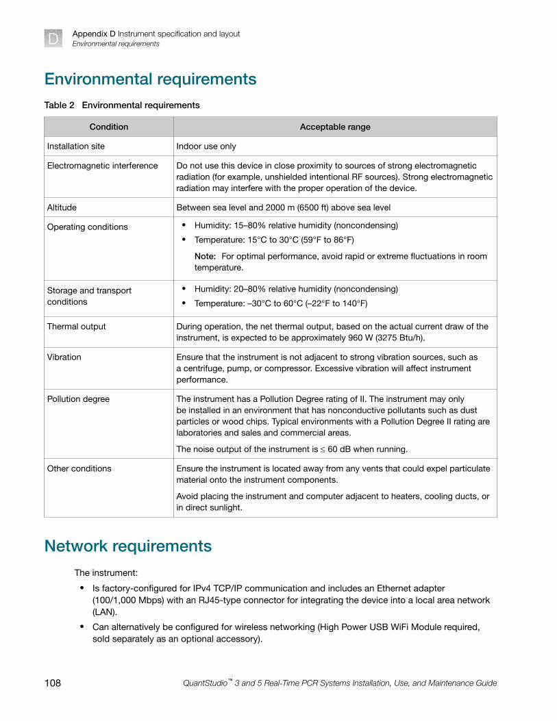
Environmental requirementsTable 2 Environmental requirements
Condition Acceptable range
Installation site Indoor use only
Electromagnetic interference Do not use this device in close proximity to sources of strong electromagneticradiation (for example, unshielded intentional RF sources). Strong electromagneticradiation may interfere with the proper operation of the device.
Altitude Between sea level and 2000 m (6500 ft) above sea level
Operating conditions • Humidity: 15–80% relative humidity (noncondensing)
• Temperature: 15°C to 30°C (59°F to 86°F)
Note: For optimal performance, avoid rapid or extreme fluctuations in roomtemperature.
Storage and transportconditions
• Humidity: 20–80% relative humidity (noncondensing)
• Temperature: –30°C to 60°C (–22°F to 140°F)
Thermal output During operation, the net thermal output, based on the actual current draw of theinstrument, is expected to be approximately 960 W (3275 Btu/h).
Vibration Ensure that the instrument is not adjacent to strong vibration sources, such asa centrifuge, pump, or compressor. Excessive vibration will affect instrumentperformance.
Pollution degree The instrument has a Pollution Degree rating of II. The instrument may onlybe installed in an environment that has nonconductive pollutants such as dustparticles or wood chips. Typical environments with a Pollution Degree II rating arelaboratories and sales and commercial areas.
The noise output of the instrument is £ 60 dB when running.
Other conditions Ensure the instrument is located away from any vents that could expel particulatematerial onto the instrument components.
Avoid placing the instrument and computer adjacent to heaters, cooling ducts, orin direct sunlight.
Network requirementsThe instrument:
• Is factory-configured for IPv4 TCP/IP communication and includes an Ethernet adapter(100/1,000 Mbps) with an RJ45-type connector for integrating the device into a local area network(LAN).
• Can alternatively be configured for wireless networking (High Power USB WiFi Module required,sold separately as an optional accessory).
Appendix D Instrument specification and layoutEnvironmental requirementsD
108 QuantStudio™ 3 and 5 Real‑Time PCR Systems Installation, Use, and Maintenance Guide

The instrument can be configured for either wired or wireless networking, not both.
If a Thermo Fisher Scientific service representative is to install the instrument:
• If the instrument will be connected to a LAN, an active, tested network jack must be in place beforethe scheduled installation date.
• A representative from your information technologies department must be available during theinstallation to help connect the instrument to your network.
Required materials to network the instrument:
• Wired—Ethernet cable of sufficient length with RJ45 connectors– CAT5 cable for a 100 Mbps network connection
– CAT5e or CAT6 cable for a 1,000 Mbps network connection
–or–
• Wireless—High Power USB WiFi Module (Cat. No. A26774, sold separately)
Appendix D Instrument specification and layoutNetwork requirements D
QuantStudio™ 3 and 5 Real‑Time PCR Systems Installation, Use, and Maintenance Guide 109

Safety
■ Symbols on this instrument . . . . . . . . . . . . . . . . . . . . . . . . . . . . . . . . . . . . . . . . . . . . . . . . . . . . . . . . . . . 110
■ Safety alerts on this instrument . . . . . . . . . . . . . . . . . . . . . . . . . . . . . . . . . . . . . . . . . . . . . . . . . . . . . . . 113
■ Safety information for instruments not manufactured by Thermo Fisher Scientific . . . . . . . . . . . . 114
■ Instrument safety . . . . . . . . . . . . . . . . . . . . . . . . . . . . . . . . . . . . . . . . . . . . . . . . . . . . . . . . . . . . . . . . . . . . 114
■ Safety and electromagnetic compatibility (EMC) standards . . . . . . . . . . . . . . . . . . . . . . . . . . . . . . . 116
■ Chemical safety . . . . . . . . . . . . . . . . . . . . . . . . . . . . . . . . . . . . . . . . . . . . . . . . . . . . . . . . . . . . . . . . . . . . . 119
■ Biological hazard safety . . . . . . . . . . . . . . . . . . . . . . . . . . . . . . . . . . . . . . . . . . . . . . . . . . . . . . . . . . . . . . 120
WARNING! GENERAL SAFETY. Using this product in a manner not specified in the userdocumentation may result in personal injury or damage to the instrument or device. Ensure thatanyone using this product has received instructions in general safety practices for laboratories andthe safety information provided in this document.
· Before using an instrument or device, read and understand the safety information provided in theuser documentation provided by the manufacturer of the instrument or device.
· Before handling chemicals, read and understand all applicable Safety Data Sheets (SDSs) and useappropriate personal protective equipment (gloves, gowns, eye protection, and so on). To obtainSDSs, see the “Documentation and Support” section in this document.
Symbols on this instrumentSymbols may be found on the instrument to warn against potential hazards or convey important safetyinformation. In this document, the hazard symbol is used along with one of the following user attentionwords:
• CAUTION!—Indicates a potentially hazardous situation that, if not avoided, may result in minor ormoderate injury. It may also be used to alert against unsafe practices.
• WARNING!—Indicates a potentially hazardous situation that, if not avoided, could result in death orserious injury.
• DANGER!—Indicates an imminently hazardous situation that, if not avoided, will result in death orserious injury.
Symbol English Français
Caution, risk of danger
Consult the manual for further safetyinformation.
Attention, risque de danger
Consulter le manuel pour d’autresrenseignements de sécurité.
E
110 QuantStudio™ 3 and 5 Real‑Time PCR Systems Installation, Use, and Maintenance Guide

(continued)
Symbol English Français
Caution, risk of electrical shock Attention, risque de choc électrique
Moving parts Parties mobiles
Caution, hot surface Attention, surface chaude
Potential biohazard Danger biologique potentiel
Ultraviolet light Rayonnement ultraviolet
Potential slipping hazard Danger de glisser potentiel
On On (marche)
Off Off (arrêt)
On/Off On/Off (marche/arrêt)
Standby En attente
Earth (ground) terminal Borne de (mise à la) terre
Protective conductor terminal (main ground) Borne de conducteur de protection (mise à laterre principale)
Terminal that can receive or supplyalternating current or voltage
Borne pouvant recevoir ou envoyer unetension ou un courant de type alternatif
Terminal that can receive or supplyalternating or direct current or voltage
Borne pouvant recevoir ou envoyer unetension ou un courant continu ou alternatif
Appendix E SafetySymbols on this instrument E
QuantStudio™ 3 and 5 Real‑Time PCR Systems Installation, Use, and Maintenance Guide 111

(continued)
Symbol English Français
Do not dispose of this product in unsortedmunicipal waste
CAUTION! To minimize negativeenvironmental impact from disposalof electronic waste, do notdispose of electronic waste inunsorted municipal waste. Followlocal municipal waste ordinancesfor proper disposal provisionand contact customer servicefor information about responsibledisposal options.
Ne pas éliminer ce produit avec les déchetsusuels non soumis au tri sélectif.
MISE EN GARDE ! Pour minimi‐ser les conséquences négatives surl’environnement à la suite de l’éli‐mination de déchets électroniques,ne pas éliminer ce déchet électro‐nique avec les déchets usuels nonsoumis au tri sélectif. Se conformeraux ordonnances locales sur les dé‐chets municipaux pour les disposi‐tions d’élimination et communiqueravec le service à la clientèle pourdes renseignements sur les optionsd’élimination responsable.
Conformity symbols
Conformity mark Description
Indicates conformity with safety requirements for Canada and U.S.A.
Indicates conformity with European Union requirements for safety andelectromagnetic compatibility.
Indicates conformity with Australian standards for electromagnetic compatibility.
Appendix E SafetySymbols on this instrumentE
112 QuantStudio™ 3 and 5 Real‑Time PCR Systems Installation, Use, and Maintenance Guide

Safety alerts on this instrumentAdditional text may be used with one of the symbols described above when more specific informationis needed to avoid exposure to a hazard. See the following table for safety alerts found on theinstrument.
English Français
CAUTION! Hazardous chemicals. Readthe Safety Data Sheets (SDSs) beforehandling.
MISE EN GARDE ! Produits chimiquesdangereux. Lire les fiches signalétiques (FS)avant de manipuler les produits.
CAUTION! Hazardous waste. Refer toSDS(s) and local regulations for handlingand disposal.
MISE EN GARDE ! Déchets dangereux.Lire les fiches signalétiques (FS) et la régle‐mentation locale associées à la manipulationet à l’élimination des déchets.
Location of safety labels on the instrument
Appendix E SafetySafety alerts on this instrument E
QuantStudio™ 3 and 5 Real‑Time PCR Systems Installation, Use, and Maintenance Guide 113
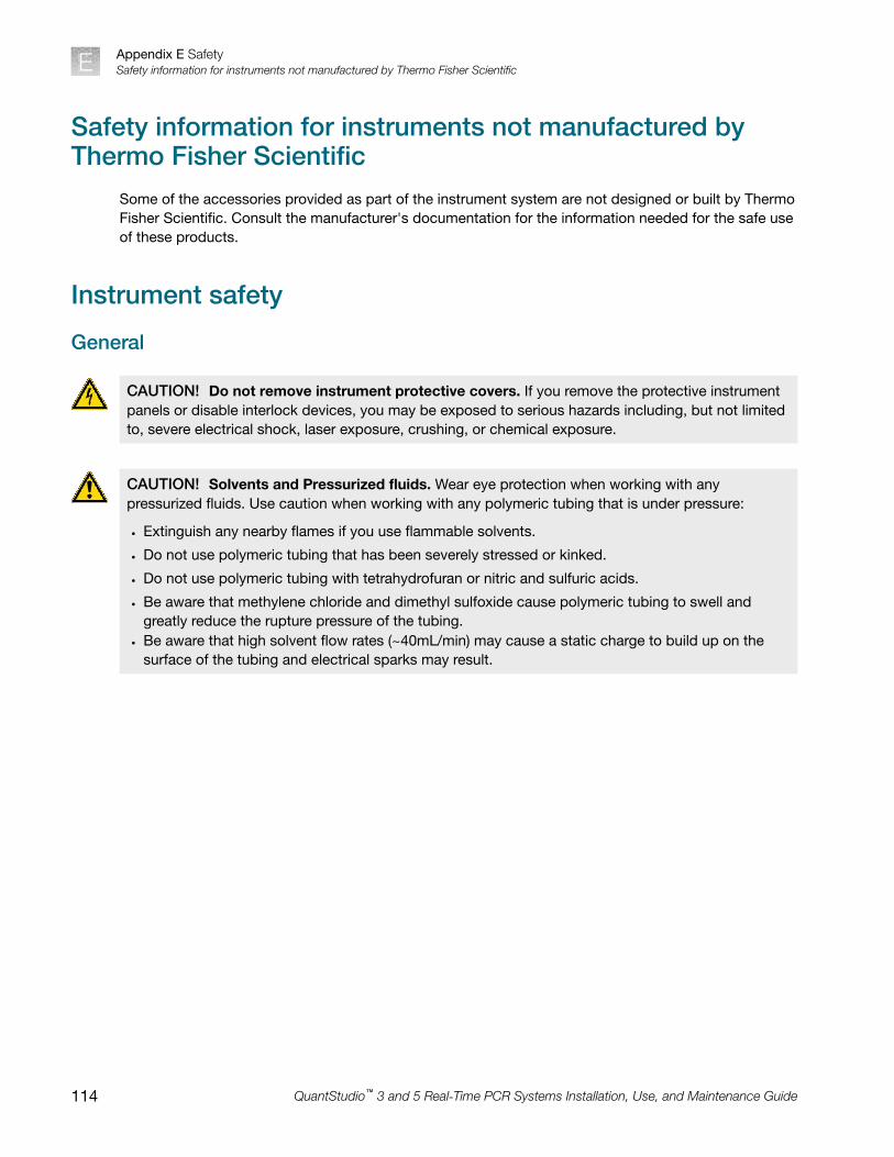
Safety information for instruments not manufactured byThermo Fisher Scientific
Some of the accessories provided as part of the instrument system are not designed or built by ThermoFisher Scientific. Consult the manufacturer's documentation for the information needed for the safe useof these products.
Instrument safety
General
CAUTION! Do not remove instrument protective covers. If you remove the protective instrumentpanels or disable interlock devices, you may be exposed to serious hazards including, but not limitedto, severe electrical shock, laser exposure, crushing, or chemical exposure.
CAUTION! Solvents and Pressurized fluids. Wear eye protection when working with anypressurized fluids. Use caution when working with any polymeric tubing that is under pressure:
· Extinguish any nearby flames if you use flammable solvents.
· Do not use polymeric tubing that has been severely stressed or kinked.
· Do not use polymeric tubing with tetrahydrofuran or nitric and sulfuric acids.
· Be aware that methylene chloride and dimethyl sulfoxide cause polymeric tubing to swell andgreatly reduce the rupture pressure of the tubing.
· Be aware that high solvent flow rates (~40mL/min) may cause a static charge to build up on thesurface of the tubing and electrical sparks may result.
Appendix E SafetySafety information for instruments not manufactured by Thermo Fisher ScientificE
114 QuantStudio™ 3 and 5 Real‑Time PCR Systems Installation, Use, and Maintenance Guide

Physical injury
CAUTION! Moving and Lifting Injury. The instrument is to be moved and positioned only by thepersonnel or vendor specified in the applicable site preparation guide. Improper lifting can causepainful and permanent back injury.
Things to consider before lifting or moving the instrument or accessories:
· Depending on the weight, moving or lifting may require two or more persons.
· If you decide to lift or move the instrument after it has been installed, do not attempt to do sowithout the assistance of others, the use of appropriate moving equipment, and proper liftingtechniques.
· Ensure you have a secure, comfortable grip on the instrument or accessory.
· Make sure that the path from where the object is to where it is being moved is clear ofobstructions.
· Do not lift an object and twist your torso at the same time. Keep your spine in a good neutralposition while lifting with your legs.
· Participants should coordinate lift and move intentions with each other before lifting and carrying.
· For smaller packages, rather than lifting the object from the packing box, carefully tilt the box on itsside and hold it stationary while someone else slides the contents out of the box.
CAUTION! Moving Parts. Moving parts can crush, pinch and cut. Keep hands clear of moving partswhile operating the instrument. Disconnect power before servicing.
WARNING! Do not attempt to lift or move the instrument without the assistance of others. Useappropriate moving equipment and proper lifting technique, improper lifting may result in seriousinjury.
Appendix E SafetyInstrument safety E
QuantStudio™ 3 and 5 Real‑Time PCR Systems Installation, Use, and Maintenance Guide 115

Electrical safety
WARNING! Fuse Installation. Before installing the instrument, verify that the fuses are properlyinstalled and the fuse voltage matches the supply voltage. Replace fuses only with the type andrating specified for the unit. Improper fuses can damage the instrument wiring system and cause afire.
WARNING! Ensure appropriate electrical supply. For safe operation of the instrument:
· Plug the system into a properly grounded receptacle with adequate current capacity.
· Ensure the electrical supply is of suitable voltage.
· Never operate the instrument with the ground disconnected. Grounding continuity is required forsafe operation of the instrument.
WARNING! Power Supply Line Cords. Use properly configured and approved line cords for thepower supply in your facility.
WARNING! Disconnecting Power. To fully disconnect power either detach or unplug the powercord, positioning the instrument such that the power cord is accessible.
Cleaning and decontamination
CAUTION! Cleaning and Decontamination. Use only the cleaning and decontamination methodsspecified in the manufacturer's user documentation. It is the responsibility of the operator (or otherresponsible person) to ensure the following requirements are met:
· No decontamination or cleaning agents are used that could cause a HAZARD as a result of areaction with parts of the equipment or with material contained in the equipment.
· The instrument is properly decontaminated a) if hazardous material is spilled onto or into theequipment, and/or b) prior to having the instrument serviced at your facility or sending theinstrument for repair, maintenance, trade-in, disposal, or termination of a loan (decontaminationforms may be requested from customer service).
· Before using any cleaning or decontamination methods (except those recommended by themanufacturer), users should confirm with the manufacturer that the proposed method will notdamage the equipment.
Safety and electromagnetic compatibility (EMC) standardsThe instrument design and manufacture complies with the following standards and requirements forsafety and electromagnetic compatibility.
Appendix E SafetySafety and electromagnetic compatibility (EMC) standardsE
116 QuantStudio™ 3 and 5 Real‑Time PCR Systems Installation, Use, and Maintenance Guide

Safety compliance
Reference Description
EU Directive 2014/35/EU European Union “Low Voltage Directive”
IEC 61010-1
EN 61010-1
UL 61010-1
CSA C22.2 No. 61010-1
Safety requirements for electrical equipment for measurement, control, andlaboratory use – Part 1: General requirements
IEC 61010-2-010
EN 61010-2-010
Safety requirements for electrical equipment for measurement, control andlaboratory use – Part 2-010: Particular requirements for laboratory equipmentfor the heating of materials
IEC 61010-2-081
EN 61010-2-081
Safety requirements for electrical equipment for measurement, control andlaboratory use – Part 2-081: Particular requirements for automatic and semi-automatic laboratory equipment for analysis and other purposes
EMC
Reference Description
Directive 2014/30/EU European Union “EMC Directive”
EN 61326-1/ IEC 61326-1 Electrical Equipment for Measurement, Control and Laboratory Use –EMC Requirements – Part 1: General Requirements
AS/NZS CISPR 11 Limits and Methods of Measurement of Electromagnetic DisturbanceCharacteristics of Industrial, Scientific, and Medical (ISM)Radiofrequency Equipment
ICES-001, Issue 4 Industrial, Scientific and Medical (ISM) Radio Frequency Generators
FCC Part 15 Subpart B (47 CFR) U.S. Standard Radio Frequency Devices
This equipment has been tested and found to comply with the limits for a Class A digital device,pursuant to part 15 of the FCC Rules. These limits are designed to provide reasonable protectionagainst harmful interference when the equipment is operated in a commercial environment. Thisequipment generates, uses, and can radiate radio frequency energy and, if not installed and usedin accordance with the instruction manual, may cause harmful interference to radio communications.Operation of this equipment in a residential area is likely to cause harmful interference in which case theuser will be required to correct the interference at his own expense.
Appendix E SafetySafety and electromagnetic compatibility (EMC) standards E
QuantStudio™ 3 and 5 Real‑Time PCR Systems Installation, Use, and Maintenance Guide 117

Environmental design
Reference Description
Directive 2012/19/EU European Union “WEEE Directive” – Waste electrical and electronic equipment
EU Directive 2011/65/EU& Commission DelegatedDirective (EU) 2015/863
European Union “RoHS Directive” – Restriction of hazardous substances inelectrical and electronic equipment
Directive 2006/66/EC European Union “Battery Directive”
China EEP Hazardous Substances Information
ComponentName
QuantStudio™ 3 and 5 Real‑Time PCR Systems
Hazardous Substances
(Pb) (Hg) (Cd) (Cr(VI)) (PBB) (PBDE)
PCBA X O O O O O
SJ/T11364. This table is compiled according to SJ/T 11364 standard.
O: GB/T26572.
Indicates that the concentration of the hazardous substance in all homogeneous materials for the part isbelow the relevant threshold of the GB/T 26572 standard.
X: GB/T26572.
Indicates that the concentration of the hazardous substance in at least one homogenous material of thepart is above the relevant threshold of the GB/T 26572 standard.
Appendix E SafetySafety and electromagnetic compatibility (EMC) standardsE
118 QuantStudio™ 3 and 5 Real‑Time PCR Systems Installation, Use, and Maintenance Guide

Chemical safety
WARNING! GENERAL CHEMICAL HANDLING. To minimize hazards, ensure laboratory personnelread and practice the general safety guidelines for chemical usage, storage, and waste providedbelow. Consult the relevant SDS for specific precautions and instructions:
· Read and understand the Safety Data Sheets (SDSs) provided by the chemical manufacturerbefore you store, handle, or work with any chemicals or hazardous materials. To obtain SDSs, seethe "Documentation and Support" section in this document.
· Minimize contact with chemicals. Wear appropriate personal protective equipment when handlingchemicals (for example, safety glasses, gloves, or protective clothing).
· Minimize the inhalation of chemicals. Do not leave chemical containers open. Use only withsufficient ventilation (for example, fume hood).
· Check regularly for chemical leaks or spills. If a leak or spill occurs, follow the manufacturercleanup procedures as recommended in the SDS.
· Handle chemical wastes in a fume hood.
· Ensure use of primary and secondary waste containers. (A primary waste container holds theimmediate waste. A secondary container contains spills or leaks from the primary container.Both containers must be compatible with the waste material and meet federal, state, and localrequirements for container storage.)
· After emptying a waste container, seal it with the cap provided.
· Characterize (by analysis if needed) the waste generated by the particular applications, reagents,and substrates used in your laboratory.
· Ensure that the waste is stored, transferred, transported, and disposed of according to all local,state/provincial, and/or national regulations.
· IMPORTANT! Radioactive or biohazardous materials may require special handling, and disposallimitations may apply.
WARNING! HAZARDOUS WASTE (from instruments). Waste produced by the instrument ispotentially hazardous. Follow the guidelines noted in the preceding General Chemical Handlingwarning.
WARNING! 4L Reagent and Waste Bottle Safety. Four-liter reagent and waste bottles can crackand leak. Each 4-liter bottle should be secured in a low-density polyethylene safety container with thecover fastened and the handles locked in the upright position.
Appendix E SafetyChemical safety E
QuantStudio™ 3 and 5 Real‑Time PCR Systems Installation, Use, and Maintenance Guide 119

Biological hazard safety
WARNING! Potential Biohazard. Depending on the samples used on this instrument, the surfacemay be considered a biohazard. Use appropriate decontamination methods when working withbiohazards.
WARNING! BIOHAZARD. Biological samples such as tissues, body fluids, infectious agents,and blood of humans and other animals have the potential to transmit infectious diseases.Conduct all work in properly equipped facilities with the appropriate safety equipment (for example,physical containment devices). Safety equipment can also include items for personal protection,such as gloves, coats, gowns, shoe covers, boots, respirators, face shields, safety glasses, orgoggles. Individuals should be trained according to applicable regulatory and company/ institutionrequirements before working with potentially biohazardous materials. Follow all applicable local,state/provincial, and/or national regulations. The following references provide general guidelines whenhandling biological samples in laboratory environment.
· U.S. Department of Health and Human Services, Biosafety in Microbiological and BiomedicalLaboratories (BMBL), 6th Edition, HHS Publication No. (CDC) 300859, Revised June 2020https://www.cdc.gov/labs/pdf/CDC-BiosafetymicrobiologicalBiomedicalLaboratories-2020-P.pdf
· Laboratory biosafety manual, fourth edition. Geneva: World Health Organization; 2020 (Laboratorybiosafety manual, fourth edition and associated monographs)www.who.int/publications/i/item/9789240011311
Appendix E SafetyBiological hazard safetyE
120 QuantStudio™ 3 and 5 Real‑Time PCR Systems Installation, Use, and Maintenance Guide

Documentation and support
Related documentation
Document Publicationnumber
Description
QuantStudio™ 3 and 5 Real‑TimePCR Systems Installation, Use, andMaintenance Guide
MAN0010408 Describes the hardware and softwareand provides information on preparing,using, maintaining, and troubleshooting thesystem.
QuantStudio™ Real‑Time PCR System Help MAN0010422 Describes the instrument touchscreen andprovides procedures for configuration,calibration, and performing a run.
QuantStudio™ Design and AnalysisDesktop Software Command-LineApplication Guide
MAN0010409 Describes how to use the command-linesoftware application and provides theprocedure to automate the creation ofnew experiment files and export data fromexisting files.
QuantStudio™ Design and AnalysisDesktop Software User Guide
MAN0010408 Describes how to design and performexperiments using the software.
QuantStudio™ Design and AnalysisDesktop Software Help
MAN0010415 Describes the software and providesprocedures for common tasks.
QuantStudio™ 5 Real‑Time PCR SystemSAE Admin Console Help
MAN0010417 Describes the SAE Administrator Consoleand provides procedures for commontasks.
QuantStudio™ 5 Real‑Time PCR SystemSAE Admin Console User Guide
MAN0010410 Describes how to use the SAEAdministrator Console.
QuantStudio™ Design and Analysis CloudSoftware Help
MAN0010414 Describes the Cloud version of thesoftware and provides procedures forcommon tasks.
QuantStudio™ 3 and 5 Real‑Time PCRSystems Site Preparation Guide
MAN0010405 Explains how to prepare your site toreceive and install the system. Intendedfor personnel who schedule, manage, andperform the tasks required to prepare thesite for installation.
Note: For additional documentation, see “Customer and technical support” on page 122.
F
QuantStudio™ 3 and 5 Real‑Time PCR Systems Installation, Use, and Maintenance Guide 121

Obtain information from the Help systemThe instrument has a Help system that describes how to use each feature of the touchscreen. Touch on the instrument touchscreen to access the Help system.
Customer and technical supportVisit thermofisher.com/support for the latest service and support information.
• Worldwide contact telephone numbers
• Product support information– Product FAQs
– Software, patches, and updates
– Training for many applications and instruments
• Order and web support
• Product documentation– User guides, manuals, and protocols
– Certificates of Analysis
– Safety Data Sheets (SDSs; also known as MSDSs)
Note: For SDSs for reagents and chemicals from other manufacturers, contact themanufacturer.
Limited product warrantyLife Technologies Corporation and/or its affiliate(s) warrant their products as set forth in theLife Technologies' General Terms and Conditions of Sale at www.thermofisher.com/us/en/home/global/terms-and-conditions.html. If you have any questions, please contact Life Technologies atwww.thermofisher.com/support.
Appendix F Documentation and supportObtain information from the Help systemF
122 QuantStudio™ 3 and 5 Real‑Time PCR Systems Installation, Use, and Maintenance Guide

Index
Aaccessories 104add to method 35administrator instrument profile 76Administrator profile 79
Bbackground calibration
create plate 52description 44plate, prepare 47
Background calibrationrun 48when to perform 43
backup instrument 11, 67barcode scan 33biohazard safety 120
Ccalibration
reminders 45Background 48custom dye. See custom dyecustom melt 65Dye 48plate, prepare 47reminders 45ROI/Uniformity 48schedule 43status 45transfer results 50view images 50workflow 46
calibration failure, troubleshoot 51Change password 85Change PIN 85Cloud server, select location 88comparative Ct runs 19computer
connection to instrument or LAN 95connections 93requirements for desktop software 94
set up 92Connect
Link to instrument 80Roles
Administrator 79Standard 79
Unlink from instrument 83Connect profile, Overview 78connect to network, workflow 90connection, not recognized consumables
384-well 10296-well 0.1-mL 10396-well 0.2-mL 101
contamination, identify 52custom dye
add to the instrument 63calibration plate, create 62calibration, perform 63description 13dilution guidelines 59optimal concentration 61wavelength requirements 59
custom dye calibration, workflow 59custom dye dilution plate, prepare 60custom melt calibration 65
Ddata collection 14data collection points, add to method 34date and time 89delete files 42desktop software
download 95download and install 94install 95
disk space message documentation, related 121download desktop software 95dye calibration
description 44plate, prepare 47
Dye calibrationrun 48
QuantStudio™ 3 and 5 Real‑Time PCR Systems Installation, Use, and Maintenance Guide 123

when to perform 43dyes
custom 13, 59system 12
EEdit profile 85EDS files, transfer 41EDT files, copy or delete 42Ethernet port 97experiment
create from template 30edit 32run from saved file 30run last 31
Ffactory defaults 87firewall ports 97fluorescence high fuses, replace 71
Ggenotyping runs 19guest profile
disable 86limits 25
HHelp system, access 122home screen, parts of 23
Iinstall, desktop software 95installation
before you begin 91desktop software 94workflow 90
instrumentprofile, create 25connections 93enable for monitoring 86move 73name 88overview 11parts of 15power off 72power on 22, 72prepare to store or move or ship 73
return for service 73touchscreen black
instrument filters 12instrument layout 105instrument settings 26instrument specification 105instrument verification. See RNase P verification
Llimited product warranty 122load plate 37, 38Local instrument profile, Overview 78lock the touchscreen 41
Mmaintenance 67melt curve runs 19melt curves, add to method 34method
add melt curves 34add stages 34add steps 34data collection points 34edit 33parts of 34pause 35ramp rate 35
Nnetwork
configurations supported 95guidelines and best practices 98wired connection set up 87wireless connection set up 88
network configuration and security 10networking 95
Oonline Help. See Help systemOrder to set up profiles 78
PPassword, Change 85password security 10pause run 40performance verification. See RNase P verificationPIN, Change 85PIN reset 76presence/absence runs 19
Index
124 QuantStudio™ 3 and 5 Real‑Time PCR Systems Installation, Use, and Maintenance Guide

ProfileConnect
Link 80Unlink 83
Edit 85profiles
administrator 76delete 76edit 77guest, disable 86instrument 25require sign-in 86reset PIN 76sign in 25
ProfilesConnect
Administrator 79Standard 79
Order to set up 78properties, enter or edit 32protocol. See method
Rreal-time plots
view on instrument touchscreen 40zoom 41
related documentation 121relative standard curve runs 19Replace with index term require sign in 86restore instrument 11, 67RNase P verification
pass criteria 55plate description 53run 56
RNase P verification, plate, prepare 55ROI/uniformity calibration
description 44plate, prepare 47
ROI/Uniformity calibrationrun 48when to perform 43
runpause or stop 40post-PCR 14real-time 14
run data, transfer 41run history 42run last experiment 31run protocol. See methodruns, types 19
SSAE mode (Security, Audit, and e‑Signature) 85safety, biohazard 120sample block
clean 68decontaminate 68
settings 26sign in, require 86sign out
profile 26timer, set 89
sleep mode 72software features 15software updates 86stages, add to method 34standard curve runs 19Standard profile 79standby mode 72startup wizard 92steps, add to method 34stop run 40support, customer and technical 122supported dyes 12symbols, safety 110system dyes 12
Ttemplate properties. See propertiesterms and conditions 122thermal protocol. See methodThermo Fisher Connect profile, Edit 85third-party software 18transfer files 42troubleshooting 99
Uuniformity calibration
description 44plate, prepare 47
unload plate 37, 38unpack instrument 91use the instrument, workflow 29
Vverification failure, troubleshoot 57
Wwarranty 122well details
Index
QuantStudio™ 3 and 5 Real‑Time PCR Systems Installation, Use, and Maintenance Guide 125

define, assign, view 36view on instrument touchscreen 40
workflow, use the instrument 29
Zzoom 41
Index
126 QuantStudio™ 3 and 5 Real‑Time PCR Systems Installation, Use, and Maintenance Guide


QS 35 Instrument UG_RUO_MAN0010407EN no translations-v12-GUID-88D256DF-7F65-4A04-B662-0DCAA6DC61A6-2021/07/21 16:29:30 en16:15:10.886+01:00thermofisher.com/support | thermofisher.com/askaquestion
thermofisher.com
22 July 2021