Man-0076r3.1, Gsc400 User Manual
129
GSC400 Automatic Gen-Set Controller Installation and User Manual MAN-0076 Rev3.1, GSC400 User Manual.doc, October 2010 GSC400 Series Automatic Gen-Set Controller Manual Revision 3.1
Transcript of Man-0076r3.1, Gsc400 User Manual
GSC400 Automatic Gen-Set Controller Installation and User Manual MAN-0076 Rev3.1, GSC400 User Manual.doc, October 2010
GSC400 Series Automatic Gen-Set Controller Manual
Revision 3.1

2 of 129
Thank You For Purchasing This DynaGen Product Please Read Manual Before Installing Unit Receipt of Shipment and Warranty Return Information Upon receipt of shipment, carefully remove the unit from the shipping container and thoroughly examine the unit for shipping damage. In case of damage, immediately contact the carrier and request that an inspection report be filed prior to contacting DynaGen. All returned items are to be shipped prepaid and include a Return Material Authorization (RMA) number issued by DynaGen. Limited Warranty For warranty information refer to the standard terms and conditions of sale at http://www.dynagen.ca. Dynagen GSC400 Webpage For up-to-date manuals and other information please see the GSC400 section of the Dynagen website at: www.dynagen.ca/products/GSC400.htm
3 of 129
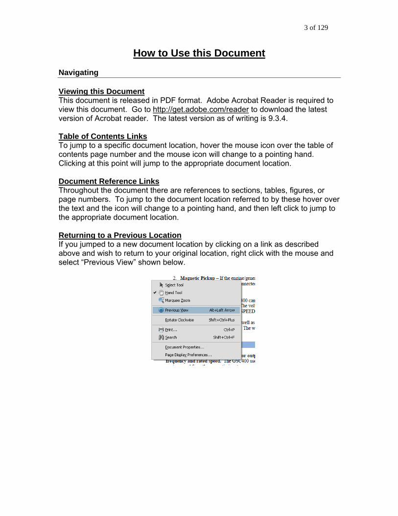
How to Use this Document Navigating Viewing this Document This document is released in PDF format. Adobe Acrobat Reader is required to view this document. Go to http://get.adobe.com/reader to download the latest version of Acrobat reader. The latest version as of writing is 9.3.4. Table of Contents Links To jump to a specific document location, hover the mouse icon over the table of contents page number and the mouse icon will change to a pointing hand. Clicking at this point will jump to the appropriate document location. Document Reference Links Throughout the document there are references to sections, tables, figures, or page numbers. To jump to the document location referred to by these hover over the text and the icon will change to a pointing hand, and then left click to jump to the appropriate document location. Returning to a Previous Location If you jumped to a new document location by clicking on a link as described above and wish to return to your original location, right click with the mouse and select “Previous View” shown below.

4 of 129
GSC400 Specifications
VDC Rating 12/24 VDC Standby Current Consumption
50 mA @ 12 VDC
Operating Temp -40°C to +85°C (-40°F to +185°F) LCD Operating Temp***
-200C to 700C (-40F to +1580F)
Function Selection Range Speed Sensing Generator pickup
Magnetic pickup 0-300vac, 0-3600rpm 0-300vac, 0-3600rpm
Voltage Sensing Single phase, Three phase, Delta, Wye
Max 700vac, +/- 1% Max 700vac, +/- 1% Max 700vac, +/- 1%
Current Sensing* Enable/Disable Max 5A, +/- 2% Frequency Sensing Enable/Disable 1 – 100 HZ Engine Temp GND=Fail, Open=Fail 10-265°F, 10-265°C
Oil Pressure GND=Fail, Open=Fail 0-90 PSI, 0-90 Kpa Oil Level GND=Fail, Open=Fail 0-90% Fuel Level GND=Fail, Open=Fail 0-100% Engine Logic Delay to start
Pre-heat Crank Rest Time Mid Heat Crank attempts False restart Post heat Warm-up Cooldown Crank oil pressure Crank Disconnect
0 – 60 seconds 0 – 60 seconds 3 – 60 seconds 1 – 60 seconds 0 – 60 seconds 1-60 tries Enable, Disabled 0 – 60 seconds 0 – 600 seconds 0-600 seconds 0-90 KPa 100-2000 RPM
Analog Input Input 2 (Low Z, Gain = 1) Input 3,4 (Low Z, Gain = 3) Input 5,7 (High Z, Gain =3) Input 6 (High Z, Gain = 1)
Gnd=Fail, Open=fail, 7mA Max Note: On LS/LX controllers Input 2 is High Z, Gain = 3 and Input 6 has a gain of 3.
Digital Input Input A-D (Sw to Bat) Input E-H (Sw to Gnd)
Bat=Fail, 7mA Max Gnd=Fail, 7mA Max
Digital Output Output A-H Extra Relay
200 mA Max 40A Max
Exerciser Enable, Disable 10-240 Minutes Battery Recharge Enable, Disable 10-240 Minutes
Function Selection Range
Password 4-Digit 0-9 LCD Display 128x64 Graphic display, Backlit, 60° viewing angle LED Display Red, Green, Yellow LED representation, Daytime Visible, 60° viewing angle Programming Manual, Software, Field upgradeable
J1939 Interface Low emission capable Relays** Replaceable 40A relays for Crank, Fuel, Extra output. 12 or 24VDC Coil
Dimensions W x H x D, 139 x 113 x 65 mm (5.47 x 4.45 x 2.56 in.) Weight 0.45 Kg (1.0 Lb)
*Use of Industry Standard CT Required. ** 40A output at room temperature. *** The LCD display will exhibit color and response time changes at high and low temperatures respectively but will not be damaged as long as within Operating Temp.

5 of 129
Abbreviated Table of Contents 1. GSC400 Controller Series -- Introduction ........................................................ 9 2. Installation and Wiring ....................................................................................... 13 3. Operation and End-User Configuration .......................................................... 33 4. Advanced Setup ................................................................................................. 58 Appendix A GSC400 Detailed Advanced Menu Layout .................................... 88 Appendix B Default Configuration Settings ......................................................... 93 Appendix C GSC400 Fixed Warning/Failure/Event Delays .............................. 97 Appendix D Accessory List................................................................................... 102 Appendix E Modbus Map ..................................................................................... 105 Appendix F J1939 Old DTC Conversion Methods ........................................... 127 Appendix G Additional Drawings ......................................................................... 128

6 of 129
Detailed Table of Contents 1. GSC400 Controller Series -- Introduction ........................................................ 9
1.1 This Manual..................................................................................................... 10 1.2 Safety / Information ........................................................................................ 10 1.3 Receiving, Handling, and Storage ............................................................... 11 1.4 GSC400 Product Number Identification ..................................................... 12
2. Installation and Wiring ....................................................................................... 13 2.1 Mounting .......................................................................................................... 13 2.2 GSC400 Component Ratings / Standards ................................................. 15 2.3 Wiring ............................................................................................................... 16 2.4 GSC400 Terminals ........................................................................................ 19 2.5 Emergency Stop / Remote Start Contacts ................................................. 23 2.6 Configurable Switched Inputs / Configurable Outputs ............................. 23 2.7 Analog Inputs / Senders / Switches ............................................................ 23 2.8 AC Voltage ...................................................................................................... 25 2.9 AC Current....................................................................................................... 28 2.10 CAN (J1939) ................................................................................................... 29 2.11 Idle Mode ......................................................................................................... 30
2.11.1 Idling Engine during Warm-up and Cool-down.................................. 30 2.11.2 Cummins Electronic Engine Idle Mode............................................... 31
3. Operation and End-User Configuration .......................................................... 33 3.1 Recommended Maintenance ....................................................................... 34 3.2 Power-up ......................................................................................................... 34
3.2.1 Controller Alarming .................................................................................... 35 3.3 Remote Start Contacts / Emergency Stop ................................................. 35 3.4 Controller States............................................................................................. 37
3.4.1 Locking the GSC400 Screen While in RUN Mode................................ 38 3.5 GSC400 Start / Stop Behavior ..................................................................... 39 3.6 Idle Mode ......................................................................................................... 40 3.7 Generator Starting and Stopping ................................................................. 40 3.8 Controller Sleep .............................................................................................. 40 3.9 GSC400 Menu System Operation ............................................................... 41 3.10 Basic Menu...................................................................................................... 41
3.10.1 Clock Setup ............................................................................................. 43

7 of 129
3.10.2 Basic Setup ............................................................................................. 43 3.10.3 Event History Log ................................................................................... 45
3.11 GSC400 LED Status Indicators ................................................................... 49 3.12 Warnings and Failures................................................................................... 52
3.12.1 Diagnostic Trouble Code Shutdowns.................................................. 52 3.12.2 EPS Supplying Load .............................................................................. 53
3.13 J1939................................................................................................................ 53 3.14 J1939 Diagnostic Trouble Code (DTC) Display ........................................ 54
3.14.1 DM1 Messages....................................................................................... 54 3.14.2 DM2 Messages....................................................................................... 55 3.14.3 DM1 Event Log: ...................................................................................... 56
4. Advanced Setup ................................................................................................. 58 4.1 J1939 Setup .................................................................................................... 62
4.1.1 Auto Power ECM ........................................................................................ 64 4.1.2 Cummins Idle Speed ................................................................................. 64 4.1.3 Diagnostic Trouble Codes (DTCs)........................................................... 64
4.2 Analog Inputs .................................................................................................. 66 4.2.1 Fuel Level Sender – Special Case .......................................................... 68 4.2.2 Electronic Sensors – 0 to 5VDC .............................................................. 68 4.2.3 GSC400 Sender Support .......................................................................... 69
4.3 Speed Sensing ............................................................................................... 71 4.3.1 Rated Speed ............................................................................................... 71
4.4 Generator (AC Voltage / Current / Frequency) Setup .............................. 72 4.4.1 AC Frequency ............................................................................................. 72 4.4.2 AC Voltage .................................................................................................. 72 4.4.3 AC Current................................................................................................... 76 4.4.4 AC Current and Voltage Calibration ........................................................ 76
4.5 Engine Logic ................................................................................................... 77 4.5.1 Startup Sequence ...................................................................................... 77 4.5.2 Shutdown Sequence.................................................................................. 78
4.6 Digital Output (Configurable Outputs) Setup ............................................. 79 4.7 Exerciser Setup .............................................................................................. 81 4.8 Digital Input (Configurable Switched Inputs) Setup .................................. 82 4.9 Battery Setup .................................................................................................. 84

8 of 129
4.9.1 Low Battery Recharge ............................................................................... 84 4.10 Password Setup ............................................................................................. 85 4.11 Set Maintain .................................................................................................... 86 4.12 Set Modbus ..................................................................................................... 86 4.13 Common Faults .............................................................................................. 86 4.14 Set Dummy Load............................................................................................ 87
Appendix A GSC400 Detailed Advanced Menu Layout .................................... 88 Appendix B Default Configuration Settings ......................................................... 93 Appendix C GSC400 Fixed Warning/Failure/Event Delays .............................. 97 Appendix D Accessory List................................................................................... 102
D.1 GSC400 Controller Harness - Accessories.............................................. 102 D.2 GSC400 Programmer .................................................................................. 102 D.3 CT’s (Current Transformers) ...................................................................... 103 D.4 Senders.......................................................................................................... 103 D.5 GSC400 replaceable 12/24VDC relays .................................................... 103 D.6 GSC400 Fusing ............................................................................................ 104
Appendix E Modbus Map ..................................................................................... 105 E.1 Communication Details ............................................................................... 105 E.2 Modbus Commands..................................................................................... 106 E.3 Register Map................................................................................................. 108
Appendix F J1939 Old DTC Conversion Methods ........................................... 127 Appendix G Additional Drawings ......................................................................... 128

9 of 129
1. GSC400 Controller Series -- Introduction
1.1 This Manual..................................................................................................... 10 1.2 Safety / Information ........................................................................................ 10 1.3 Receiving, Handling, and Storage ............................................................... 11 1.4 GSC400 Product Number Identification ..................................................... 12
The GSC400 is designed for use on generator sets with either mechanical or electronic (J1939) engines. It can monitor analog data from senders on the engine and generator such as oil pressure, coolant temperature, current, voltage, and engine speed and generator frequency. The GSC400 can also gather engine parameters from the engine ECM via J1939 and use them to control the engine or for display purposes.
w
An RS232 interface is provided that allows communication with the DynaGen GSC400 PC Interface to change settings or display information on the PC. An RS485 port is provided for Modbus communications (slave only) for remote annunciation or communications. In addition to the monitoring features, the GSC400 controller can be used to automatically start/stop a generator system as well as provide protective warnings or shutdowns.
GSC400 Front Vie
GSC400 Back View

10 of 129
1.1 This Manual This manual is divided into three main sections:
1. Installation and Wiring 2. Day to Day User Operation and Configuration 3. Advanced Configuration for Technicians
In addition there are appendixes that contain detailed supplementary information. 1.2 Safety / Information Generator systems contain high voltage circuitry. Failing to power down and lock out equipment can cause damage to the equipment, or injury or death to personnel. The symbols below will be used in this document to classify information. Indicates something that you should take special note of
but that is not a threat to safety.
Indicates a potential for injury or death.
This is similar to Danger above but relates specifically to conditions where high voltage is encountered.
The following general safety precautions should be followed:
1. The GSC400 may carry high Voltage/Current which can cause serious
injury or death. Extreme caution must be exercised when connections are being made or broken from the controller. All wiring connections must be de-energized before any installations are performed. Wiring of the GSC400 should be performed by qualified electricians only.
2. AC power may carry high Voltage/Current which can cause serious injury
or death. De-energize all AC power sources before any connections are performed.
3. NEVER energize AC power with AC current sensing connector unplugged. An energized, unplugged connector could result in severe injury or death. Never unplug an energized connector.

11 of 129
1.3 Receiving, Handling, and Storage
Receiving: Every effort is made to ensure that your GSC400 gen-set controller arrives at its destination undamaged and ready for installation. The packaging is designed toprotect the GSC400 internal components as well as the enclosure. Care shouldbe taken to pr
otect the equipment from impact at all times. Do not remove the o
ct the e occurred
es a variety of product and
ach GSC400 controller is packaged in its own box. Do not discard the packing aterial until the controller is ready for installation.
protective packaging until the equipment is at the installation site and ready tbe installed.
When the GSC400 reaches its destination, the customer should inspeshipping box and controller for any signs of damage that may havduring transportation. Any damage should be reported to a DynaGen representative after a thorough inspection has been completed.
A shipping label affixed to the shipping box includshipping information, such as items and Customer numbers. Make certain that this information matches your order information.
Em
Handling: As previously mentioned, each GSC400 gen-set controller is packaged in its own individual box. Protect the equipment from impact at all times and do not
at the installation site and ready to be stalled, the packaging material may be removed.
carelessly stack. Once the controller is in
Storage: Although well packaged, this equipment is not suitable for outdoor storage. If GSC400 is to be stored indoors for any period of time, it should be stored withprotective packaging in place. Protect the controller at all times from excessmoisture, dirty conditions, corrosive conditions, and other contaminants. It isstrongly reco
the its
ive
mmended that the package-protected equipment be stored in a ate-controlled environment of -20 to 65°C (-4 to 149°F), with a relative
p of the stored
climhumidity of 80% or less. Do not stack other equipment on tocontrollers.

12 of 129
1.4 GSC400 Product Number Identification The GSC400 series product numbering scheme (i.e. product number)
stomer – about the unit. A product number has the format given in Figure 1.
ontroller under the bar code.
Figure 1 – GSC400 product numbering scheme
provides various information – including options selected by the cu
The product number is located on the backside of the GSC400 c

13 of 129
2. Installation and Wiring This section contains information on the installation and wiring of the GSC400 controller. Information on the configuration of the GSC400 is covered in section 4 starting on page 58. Also refer to section 3 on page 33 to learn how to operate the GSC400.
2.1 Mounting .......................................................................................................... 13 2.2 GSC400 Component Ratings / Standards ................................................. 15 2.3 Wiring ............................................................................................................... 16 2.4 GSC400 Terminals ........................................................................................ 19 2.5 Emergency Stop / Remote Start Contacts ................................................. 23 2.6 Configurable Switched Inputs / Configurable Outputs ............................. 23 2.7 Analog Inputs / Senders / Switches ............................................................ 23 2.8 AC Voltage ...................................................................................................... 25 2.9 AC Current....................................................................................................... 28 2.10 CAN (J1939) ................................................................................................... 29 2.11 Idle Mode ......................................................................................................... 30
2.11.1 Idling Engine during Warm-up and Cool-down.................................. 30 2.11.2 Cummins Electronic Engine Idle Mode............................................... 31
2.1 Mounting The GSC400 gen-set controller must be properly mounted for safe operation. Caution must be taken at the installation site to make sure the site is free from excessive moisture, fluctuating temperatures, dust, corrosive materials etc. The controller should be safely mounted in a secure location using the 3 mounting screws provided. See Figure 2 for the mounting locations. Caution: Mounting screws must be installed at the recommended torque of 10 inch pounds. Figure 3 below gives the precise dimensions of the mounting hardware.
s
Figure 2 – GSC400 Mounting Location
14 of 129
Figure 3 - Dimensions of mounting holes.

15 of 129
2.2 GSC400 Component Ratings / Standards UL Listing The GSC400 is UL listed to UL508. For conditions of acceptability refer to UL file number: E250327 or contact DynaGen. The conditions of acceptability are packaged with every unit. 12V / 24V Operation The GSC400 controller can be placed in either 12V or 24V electrical systems. The user must order the correct GSC400 as 12V operation requires 12V relays and 24V operation requires 24V relays. Relays The GSC400 comes preinstalled with the correct relays depending on the product number specified when ordered (see section 1.4 on page 12). Contact DynaGen if replacement relays are required (quote Dynagen Part numbers from Table 26 on page 104). UL Listed relays for 12 or 24VDC system operation are as follows:
• HASCO CAR-1A-40-DC12-S for 12VDC operation • HASCO CAR-1A-40-DC24-S for 24VDC operation
CAUTION: The above relays must be installed in the GSC400 for it to meet UL. Relay Fuses The GSC400 three relay outputs (crank, fuel, and extra) have external replaceable 40A fuses. CAUTION needs to be taken when connecting relay outputs to an inductive load. Due to the inductive nature of certain loads (starters, pull coils), initial current draw may be higher than stated in the load specs which could damage the onboard relays. Output relays are protected by onboard 40A fuse protection. Smaller amperage fuses from many automotive stores may be used in place of the higher current 40A. If installing lower amperage fuse protection, be certain that the current draw on each relay does not exceed the fuse current limit. An approved 40A fuse is:
• LITTLEFUSE – 257040 (32VDC, 40A, auto fast action)
16 of 129
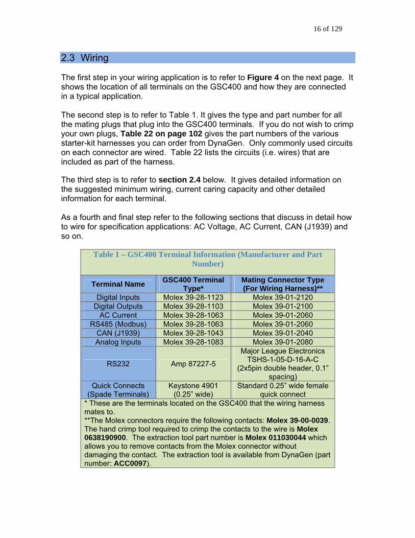
2.3 Wiring The first step in your wiring application is to refer to Figure 4 on the next page. It shows the location of all terminals on the GSC400 and how they are connected in a typical application. The second step is to refer to Table 1. It gives the type and part number for all the mating plugs that plug into the GSC400 terminals. If you do not wish to crimp your own plugs, Table 22 on page 102 gives the part numbers of the various starter-kit harnesses you can order from DynaGen. Only commonly used circuits on each connector are wired. Table 22 lists the circuits (i.e. wires) that are included as part of the harness. The third step is to refer to section 2.4 below. It gives detailed information on the suggested minimum wiring, current caring capacity and other detailed information for each terminal. As a fourth and final step refer to the following sections that discuss in detail how to wire for specification applications: AC Voltage, AC Current, CAN (J1939) and so on.
Table 1 – GSC400 Terminal Information (Manufacturer and Part Number)
Terminal Name GSC400 Terminal Type*
Mating Connector Type (For Wiring Harness)**
Digital Inputs Molex 39-28-1123 Molex 39-01-2120 Digital Outputs Molex 39-28-1103 Molex 39-01-2100
AC Current Molex 39-28-1063 Molex 39-01-2060 RS485 (Modbus) Molex 39-28-1063 Molex 39-01-2060
CAN (J1939) Molex 39-28-1043 Molex 39-01-2040 Analog Inputs Molex 39-28-1083 Molex 39-01-2080
RS232 Amp 87227-5
Major League Electronics TSHS-1-05-D-16-A-C
(2x5pin double header, 0.1” spacing)
Quick Connects (Spade Terminals)
Keystone 4901 (0.25” wide)
Standard 0.25” wide female quick connect
* These are the terminals located on the GSC400 that the wiring harness mates to. **The Molex connectors require the following contacts: Molex 39-00-0039. The hand crimp tool required to crimp the contacts to the wire is Molex 0638190900. The extraction tool part number is Molex 011030044 which allows you to remove contacts from the Molex connector without damaging the contact. The extraction tool is available from DynaGen (part number: ACC0097).

Figure 4 – General GSC400 System Wiring Diagram

Figure 5 – Digital IO Example
19 of 129
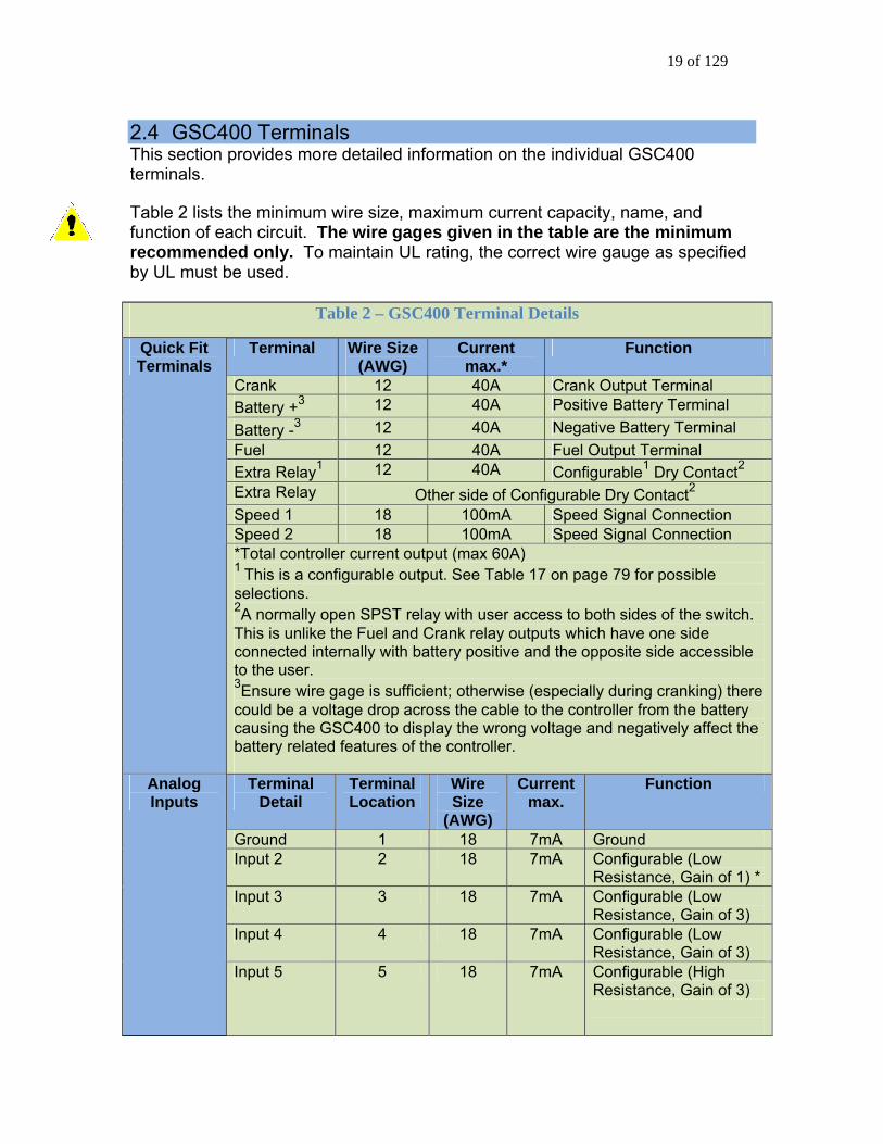
2.4 GSC400 Terminals This section provides more detailed information on the individual GSC400 terminals. Table 2 lists the minimum wire size, maximum current capacity, name, and function of each circuit. The wire gages given in the table are the minimum recommended only. To maintain UL rating, the correct wire gauge as specified by UL must be used.
Table 2 – GSC400 Terminal Details
Terminal Wire Size (AWG)
Current max.*
Function
Crank 12 40A Crank Output Terminal Battery +3 12 40A Positive Battery Terminal Battery -3 12 40A Negative Battery Terminal Fuel 12 40A Fuel Output Terminal Extra Relay1 12 40A Configurable1 Dry Contact2
Extra Relay Other side of Configurable Dry Contact2
Speed 1 18 100mA Speed Signal Connection Speed 2 18 100mA Speed Signal Connection
Quick Fit Terminals
*Total controller current output (max 60A) 1 This is a configurable output. See Table 17 on page 79 for possible selections. 2A normally open SPST relay with user access to both sides of the switch. This is unlike the Fuel and Crank relay outputs which have one side connected internally with battery positive and the opposite side accessible to the user. 3Ensure wire gage is sufficient; otherwise (especially during cranking) there could be a voltage drop across the cable to the controller from the battery causing the GSC400 to display the wrong voltage and negatively affect the battery related features of the controller.
Terminal Detail
Terminal Location
Wire Size
(AWG)
Current max.
Function
Ground 1 18 7mA Ground Input 2 2 18 7mA Configurable (Low
Resistance, Gain of 1) * Input 3 3 18 7mA Configurable (Low
Resistance, Gain of 3) Input 4 4 18 7mA Configurable (Low
Resistance, Gain of 3)
Analog Inputs
Input 5 5 18 7mA Configurable (High Resistance, Gain of 3)

20 of 129
Input 6 6 18 7mA Configurable (High Resistance, Gain of 1) **
Input 7 7 18 7mA Configurable (High Resistance, Gain of 3)
5V out *** 8 18 7mA Power for electronic sensors. ***
* LSB/LXB controllers only. For LS/LX controllers, this input spec is High Resistance, Gain of 3. ** LSB/LXB controllers only. For LS/LX controllers this input has a gain of 3. *** LSB/LXB controllers only. For LS/LX controllers this terminal is a ground. Terminal
Detail Terminal Location
Wire Size
(AWG)
Current max.
Function
Input H - GND
1 18 7mA Configurable1, 3
Input G - GND
2 18 7mA Configurable1, 3
Input F - GND
3 18 7mA Configurable1, 3
Input E - GND
4 18 7mA Configurable1, 3
Input D - BAT
5 18 7mA Configurable2, 3
Input C - BAT
6 18 7mA Configurable2, 3
Input B - BAT
7 18 7mA Configurable2, 3
Input A - BAT
8 18 7mA Configurable2, 3
Emer. Stop 9 18 7mA Allows Manual Emergency Stop (Open = Active)
Start/Stop (Remote Start Contacts)
10 18 7mA Allows Manual Start/Stop of Engine (Active = Start, Inactive = Stop)
Ground 11 18 7mA Ground Ground 12 18 7mA Ground
Digital Inputs
1 Ground input to generate logic high. 2 Tie input to battery + to generate logic high. 3See Table 18 on page 82 for possible selections.
21 of 129
Terminal Detail
Terminal Location
Wire Size
(AWG)
Current max.
Function
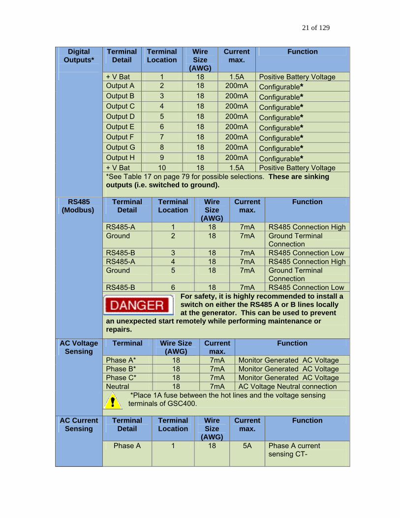
+ V Bat 1 18 1.5A Positive Battery Voltage Output A 2 18 200mA Configurable* Output B 3 18 200mA Configurable* Output C 4 18 200mA Configurable* Output D 5 18 200mA Configurable* Output E 6 18 200mA Configurable* Output F 7 18 200mA Configurable* Output G 8 18 200mA Configurable* Output H 9 18 200mA Configurable* + V Bat 10 18 1.5A Positive Battery Voltage
Digital Outputs*
*See Table 17 on page 79 for possible selections. These are sinking outputs (i.e. switched to ground).
Terminal Detail
Terminal Location
Wire Size
(AWG)
Current max.
Function
RS485-A 1 18 7mA RS485 Connection HighGround 2 18 7mA Ground Terminal
Connection RS485-B 3 18 7mA RS485 Connection Low RS485-A 4 18 7mA RS485 Connection HighGround 5 18 7mA Ground Terminal
Connection RS485-B 6 18 7mA RS485 Connection Low
RS485 (Modbus)
For safety, it is highly recommended to install a switch on either the RS485 A or B lines locally at the generator. This can be used to prevent
an unexpected start remotely while performing maintenance or repairs.
Terminal Wire Size (AWG)
Current max.
Function
Phase A* 18 7mA Monitor Generated AC Voltage Phase B* 18 7mA Monitor Generated AC Voltage Phase C* 18 7mA Monitor Generated AC Voltage Neutral 18 7mA AC Voltage Neutral connection
AC Voltage Sensing
*Place 1A fuse between the hot lines and the voltage sensing terminals of GSC400.
Terminal Detail
Terminal Location
Wire Size
(AWG)
Current max.
Function AC Current Sensing
Phase A 1 18 5A Phase A current sensing CT-
22 of 129
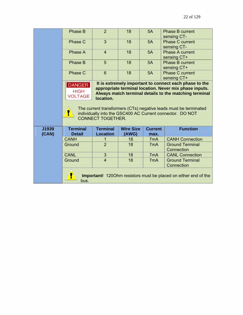
Phase B 2 18 5A Phase B current sensing CT-
Phase C 3 18 5A Phase C current sensing CT-
Phase A 4 18 5A Phase A current sensing CT+
Phase B 5 18 5A Phase B current sensing CT+
Phase C 6 18 5A Phase C current sensing CT+
It is extremely important to connect each phase to the appropriate terminal location. Never mix phase inputs. Always match terminal details to the matching terminal location.
The current transformers (CTs) negative leads must be terminated individually into the GSC400 AC Current connector. DO NOT CONNECT TOGETHER.
Terminal
Detail Terminal Location
Wire Size (AWG)
Current max.
Function
CANH 1 18 7mA CANH Connection Ground 2 18 7mA Ground Terminal
Connection CANL 3 18 7mA CANL Connection Ground 4 18 7mA Ground Terminal
Connection
J1939 (CAN)
Important! 120Ohm resistors must be placed on either end of the bus.

23 of 129
2.5 Emergency Stop / Remote Start Contacts Emergency Stop Input Pin 9 of the configurable switch input connector must be grounded (can use pins 11 or 12) to disable the emergency stop feature. When enabled the emergency stop feature forces the controller to remain in the OFF mode and sounds the buzzer. Remote Start Contacts A normally open switch needs to be placed across pin 10 of the configurable switch input connector and ground (pin 11 or 12 can be used). When the switch closes the GSC400 will start the genset. When the switch opens the GSC400 will stop the genset. 2.6 Configurable Switched Inputs / Configurable Outputs Configurable Switched Inputs Four of the switched inputs (A to D) trigger when battery + is applied. The other four (E to H) trigger when ground (battery -) is applied. The switch inputs can each be programmed by the user (e.g. low oil pressure failure) to determine the GSC400 action when triggered. See Table 18 on page 82 for a list of all possible actions. Configurable Switched Outputs All 8 of the switched outputs switch the output pin to ground when activated. For example if a switched output is used to turn on a relay one side of the relay coil must be connected to the switched output and the other side must be connected to battery +. Each switched output can be programmed by the user to activate on an event that occurs in the controller (e.g. low AC voltage failure). See Table 17 on page 79 for a list of all events that can trigger the switched outputs. 2.7 Analog Inputs / Senders / Switches The user has the option of connecting either senders or switches to the analog inputs. See section 4.2 on page 66 for info on how to program the GSC400 analog inputs. Switches If using switches they must be switched to ground but can be either normally open or normally closed.
24 of 129
Senders – Resistive If the maximum resistance of the sender you are using is less than 500Ohms then use inputs 2, 3 or 4 (3 or 4 are recommended). Otherwise use inputs 5, 6, or 7 (5 or 7 are recommended). Out of the box, the GSC400 supports several oil pressure and engine temperature senders on pins 3 and 4 only (see Table 12 on page 69). If you have a sender that is not listed in Table 12 or have it on a pin other than 3 or 4 you must use the GSC400 PC Interface Sender Utility to load the sender table (refer to manual MAN-0079, the GSC400 PC Interface manual). Temperature senders often do not measure low temperatures. The temperature range of the sender that Dynagen stocks is 1300F to 3300F. If the temperature is below 1300F the controller will display 1300F. If the temperature is above 3300F the controller will display 3300F. The same behavior applies to other sender types such as oil pressure. 0-5VDC Sensors 5VDC sensors can be attached to input #2 or #6 only. The user must convert the voltage to an equivalent resistance to fool the GSC400 into thinking the sensor is resistive. Then a sender table must be created using the resistance vs. value data. See manual MAN-0079 (GSC400 PC Interface Guide) for more information on creating and using sender tables. Temperature and Oil Pressure senders can be ordered from Dynagen. Dynagen also caries electronic oil pressure senders which are much more reliable for heavy duty applications than the resistance type. See section D.4 on page 103 for the list of senders.

25 of 129
2.8 AC Voltage The GSC400 controller requires a neutral reference. All voltages are measured line to neutral and then converted for display as line to line if required.
Do not place more than 600VAC line to line on the GSC400 AC Voltage terminals.
There should also be 1A fuses placed in series with the voltage sensing
wires to the GSC400 – see Figure 4 above. The GSC400 supports the following voltage configurations (Refer to Figure 6 below for three phase configurations):
1. Single Phase a. Two Wire b. Three Wire
2. Three Phase a. Ungrounded Delta (1:1 transformers required to create a neutral
reference) b. Center Grounded Delta c. Center Grounded Wye d. Center Grounded Wye with mid-tapped voltage sensing
Corner Grounded Delta configurations are not supported.
With Ungrounded Delta and Center Grounded Wye configurations it is possible to use 2:1 voltage transformers to step down the voltage by ½. This allows AC voltage sensing up to 1200VAC line to line. This is not possible for corner grounded delta (4-wire delta) configurations or Wye with mid-tapped voltage sensing configurations. Refer to Figure 7 below. Refer to section 4.4.2 on page 72 for how to program the GSC400 to work for your voltage configuration.

Figure 6 – GSC400 Three Phase Voltage Configurations

Figure 7 – Three Phase AC Voltage Step down Options

28 of 129
2.9 AC Current The GSC400 controller is designed to measure AC current from the generator
e with the use of current transformers (CTs). CTs with a rating of 5A on thsecondary are required. The maximum current on the AC current terminals of
e GSC400 is 5A.
For single phase two wire applications
th Current transformers are required for display of AC current. One CT is required for each phase to be displayed. The wiring for CTs is as follows:
For single phase three wire applications• CT #1 leads to terminals Phase A+ and A-.
• CT #1 leads to terminals Phase A+ and A-. • CT #2 leads to terminals Phase B+ and B-.
For three phase applications • CT #1 leads to terminals Phase A+ and A-. • CT #2 leads to terminals Phase B+ and B-. • CT #3 leads to terminals Phase C+ and C-.
ative. is
y
For CTs with wire leads the white wire is positive and the black wire is negNote that the polarity dot or “H1” marking faces towards the power source. ThH1 side is in phase with the X1 terminal or white wire. The current transformers (CTs) negative leads must be terminated individuallinto the GSC400 AC Current connector. Do not tie the negative leads together to a common neutral. See the system wiring diagram (Figure 4 on page 17) for more details.
Figure 8 – CT Installation Do’s and Don’ts (from DWG1469R1.0)

29 of 129
2.10 CAN (J1939) Refer to section 4.1 on section 62 for information on how to configure the GSC400 for J1939. ECM Power
he GSC400 fuel relay output is usually used to power the ECM. The fuel relay eat (even if no output is set to preheat). If the preheat
to detect the cranking of the ngine.
Tturns on at the start of prehtime is set to zero the fuel output turns on during the start of cranking. The ECM must be given time to boot-up to allow ite Bus Termination The CAN communication bus’s CANL and CANH lines must be terminatwith 120Ohm resistors on either end of the bus. If you are not connectinan existing bus you must do this. If you are connect
ed g to
ing to an existing bus check
istance disconnect the CAN bus harness from the SC400 and measure across the CANH and CANL pins on the harness
easure s the
n oes
a terminating resistor.
that it has the proper terminating resistors. To check for proper resGconnector. It should be 60 Ohms (two 120 Ohms in parallel). If you m20Ohm n only one resistor has been installed. 1
If using the optional J1939 harness DWG1373R3-5 from Dynagen there is a 120Ohm resistor built in. It can be cut out if the GSC400 is not the last device othe bus. If you are using DWG1375R2-5 this version of the J1939 harness dnot have Troubleshooting Notes
1. To check for proper CAN communications place GSC400 in AUTO mode and check that engine temperature on the front panel display is not displaying N/A (engine temperature must be set to J1939). “N/A” indicates no communications with the ECM.
2. The ECM should start and run the engine – even if there are no CAN
communications with GSC400 – when the GSC400 turns on the fuel and crank outputs. The GSC400 just would not stop the crank cycle when the engine is started. If the ECM is not starting then there is an issue with the wiring on the ECM. Most ECMs have multiple power and ignition inputs that must be connected for it to operate properly.

30 of 129
2.11 Idle Mode For generators that have the capability of idling at a lower speed than the speed at which power is produced, the GSC400 controller has an Idle Mode feature that suppresses the warnings and failures for under-voltage, under-frequency, and under-speed. The GSC400 displays “Idle Running” when this feature is enabled. Idle Mode Switched Input The controller enters and remains in Idle Mode as long as the “Idle Mode” configurable switched input is active. See Table 18 on page 82 for more information on the configurable switched inputs. Switched Output Option If the user requires a configurable switched output to be used during Idle Mode, the “Voltage Regulator” switched output feature can be used. It is inactive (high) when the controller is in Idle Mode or the fuel output is off and active (grounded) when the controller is not in Idle Mode. See Table 17 on page 79 for more information on the GSC400 switched outputs. The output is usually used to turn off the generator voltage regulator but can be used for any purpose.
2.11.1 Idling Engine during Warm-up and Cool-down For us section 4.5 on page 77 for more info
atures) the “Warm-up” and “Cool-down” switched outputs can be tied to the (shown in Figure 9
elow).
ers who have engines that idle during warm-up and/or cool-down (Seermation on the Warm-up and Cool-down
fe“Idle Mode” switched input via one or two external relaysb Refer to the previous section to setup the Idle Mode Switched Input and then follow the diagram below.

31 of 129
Figure 9 – Idle Mode during warm-up and cool-down application note.
2.11.2 Cummins Electronic Engine Idle Mode For Cummins electronic engines the GSC400 will control the engine using the J1939 speed control feature. Whenever the Idle Mode configurable switched input is active the GSC400 will send a command over J1939 to put the engine into idle. This feature must be enabled in the GSC400 menu or PC Interface in order to work. Refer to section 4.1.2 on page 64 for more information on how to setup this feature.

32 of 129
This page intentionally left blank.

33 of 129
3. Operation and End-User Configuration This section will explain how to operate the GSC400 and the settings the end user can
.... 34 .............................................................................. 34
3.2.1 Controller Alarming .................................................................................... 35 3.3 Remote Star ................................. 35 3.4 Controller States............................................................................................. 37
3.4.1 L 00 Screen While in RUN M ................... 38 r ..................................................................... 39
........tarting and Stopping
........... 40 Operatio 41
......................... ..... 41 3.10.1 Clock Setup ............................................................................................. 43 3.10.2 Basic Setup ............................................................................................. 43
icators .3.12 Warnings and Failures................................................................................... 52
3.12.1 Diagnostic Trouble Code Shutdowns.................................................. 52 upplying Load .............................................................................. 53
53
g: ...................................................................................... 56
change (such as the time and date).
3.1 Recommended Maintenance ...................................................................3.2 Power-up ...........................
t Contacts / Emergency Stop ................
ocking the GSC4 ode.............3.5 GSC400 Start / Stop Behavio3.6 Idle Mode ............................... .................................................................. 40 3.7 Generator S ................................................................. 40 3.8 Controller Sleep ................. ..................................................................
n3.9 GSC400 Menu System ...............................................................3.10 Basic Menu........... .............................................................
3.10.3 Event History Log ................................................................................... 45 3.11 GSC400 LED Status Ind .................................................................. 49
3.12.2 EPS S3.13 J1939................................................................................................................3.14 J1939 Diagnostic Trouble Code (DTC) Display ........................................ 54
3.14.1 DM1 Messages....................................................................................... 54 3.14.2 DM2 Messages....................................................................................... 553.14.3 DM1 Event Lo
34 of 129
3.1 The
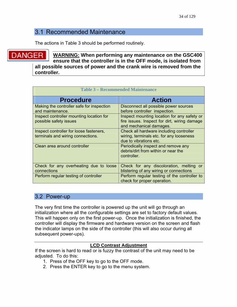
Recommended Maintenance
actions in Table 3 should be performed routinely. WARNING: When performing any maintenance on the GSC400 ensure that the controller is in the OFF mode, is isolated from
all possible sources of power and the crank wire is removed from the controller.
Table 3 – Recommended Maintenance
Procedure Action Making the controller safe for inspection and maintenance.
Disconnect all possible power sources before controller inspection.
Inspect controller mounting location for possible safety issues
Inspect mounting location for any safety or fire issues. Inspect for dirt, wiring damage and mechanical damages.
Inspect controller for loose fasteners, terminals and wiring connections.
Check all hardware including controller wiring, terminals etc. for any looseness due to vibrations etc.
Clean area around controller Periodically inspect and remove any debris/dirt from within or near the controller.
Check for any overheating due to loose connections
Check for any discoloration, melting or blistering of any wiring or connections
Perform regular testing of controller Perform regular testing of the controller to check for proper operation.
3.2 Power-up The very first time the controller is powered up the unit will go through an initialization where all the configurable settings are set to factory default valueThis will happen only on the first power-up. Once the initialization is finished, the controller will display the firmware and hardware version on the screen and f
s.
lash e indicator lamps on the side of the controller (this will also occur during all th
subsequent power-ups).
LCD Contrast Adjustment If the screen is hard to read or is fuzzy the contrast of the unit may need to be djusted. To do this: a
1. Press of the OFF key to go to the OFF mode. 2. Press the ENTER key to go to the menu system.

35 of 129
3. Press the DOWN key until “Basic Setup” is highlighted and press the enter key.
4. Press the down key to select “Contrast Adj.” and press enter. 5. Use the up and down keys to adjust the contrast and then press enter. 6. Then scroll up to select “Back” and press enter. Repeat this again to exit
the menu system and go back to the OFF mode. The controller will then enter the OFF mode. By default, it is possible to manually start the generator in the OFF Mode. The user can disable manual start in OFF mode in the basic menu (in which case the GSC400 must be in the AUTO mode to manually start the generator). See section 3.10.2 on page 43 for the basic menu. Pressing the Auto key will cause the controller to enter the AUTO mode. From this mode, the user can manually put the controller into RUN mode (i.e. start the generator) or the controller itself will be able to start the generator automatically if required (e.g. remote start capability on low battery if enabled). The controller has the ability to remember whether it was in the OFF or AUTO mode the last time it was powered up and will reenter that mode when it is repowered. 3.2.1 Controller Alarming If the emergency stop input of the digital input terminal is not connected to ground the controller will alarm and display “Emergency Stop” when connected. Emergency Stop also forces the controller to the OFF mode. To prevent this ground the emergency stop input (pin 9) to either of the grounds (pins 11 or 12) on the digital input terminal. See Figure 4 on page 17. 3.3 Remote Start Contacts / Emergency Stop The GSC400 has a dedicated remote start contact located on the digital input connector. See Figure 4 on page 17 for the location of the remote start contact. A grounded signal on the contact when the controller is in AUTO mode (see below for more information on the AUTO mode) will cause the controller to start. Removing the ground will cause the controller to go back into AUTO mode. It is also possible to set one of the programmable digital inputs as a remote start contact. This feature works the same way as the dedicated remote start (active = start). See Table 18 on page 82 for more information on the digital input features. The GSC400 also has a dedicated emergency stop input that when open will stop the generator immediately and the controller will enter the OFF mode (see below for more information on the OFF mode) and remain in the OFF mode until

36 of 129
the emergency stop input is e GSC400 will sound an a
grounded. While the emergency stop input is active udible alarm and display “Emergency Stop” on the
he emergency stop inp
thLCD display. See Figure 4 on page 17 for the location of t
ut.
37 of 129
3.4 The G ry modes of operation:
1. 2. 3.
1.
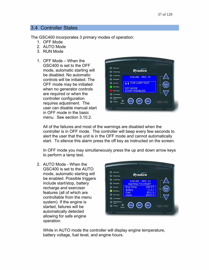
F
initiated
quires adjustment. The
nds to
the off key as instructed on the screen.
operation.
While in AUTO mode the controller will display engine temperature, battery voltage, fuel level, and engine hours.
Controller States
SC400 incorporates 3 primaOFF Mode AUTO Mode RUN Mode
OFF Mode – When the GSC400 is set to the OFmode, automatic starting willbe disabled. No automatic controls will be initiated. The OFF mode may bewhen no generator controls are required or when the controller configuration reuser can disable manual start in OFF mode in the basic menu. See section 3.10.2. All of the failures and most of the warnings are disabled when the controller is in OFF mode. The controller will beep every few secoalert the user that the unit is in the OFF mode and cannot automatically start. To silence this alarm press In OFF mode you may simultaneously press the up and down arrow keys to perform a lamp test.
2. AUTO Mode - When the GSC400 is set to the AUTO mode, automatic starting will be enabled. Possible triggers include start/stop, battery recharge and exerciser features (all of which are controllable from the menu system). If the engine is started, failures will be automatically detected allowing for safe engine

38 of 129
3. RUN Mode – The controller starts the engine/generator and enters the RUN mode automatically on certain triggers (low battery voltage or to exercise the generator) or the user can manually start the engine/generator by
. pressing the Run keyon is to uAnother opti
remote start contactsse the located
n to allow the user to monitor the engine status. e speed, generator voltage and current, and engine as others. The parameters are displayed in groups
6
will be displayed.
on the digital input connector. The controller will automatically shut the GenSet down and re-enter the AUTO mode if it initiated an engine/generator start. When the controller is in the OFF mode automatic starting is disabled. When the controller is in the RUN mode, generator parameters will be displayed on the screeThese include engintemperature as welland the screen scrolls between the various groups. The Page Roll Display menu option controls how long each parameter group is displayed on the screen before moving on to the next group. See Table on page 44 for more information. If an analog input is set to a Switch the GSC400 will display “SW” where normally the value is displayed. If the analog input is set to J1939 or an Input Pin then the actual value of the input
3.4.1 Locking the GSC400 Screen While in RUN Mode
e ENTER key to lock the layed on the top right hand side of the
When in the RUN mode the GSC400 LCD screen can be locked to display a particular parameter group. To do this press the up or down keys to scroll to the arameter group you wish to view and then press thp
screen. You will see a lock symbol dispisplay just under the date and time. d
To unlock the screen press “Enter” again which causes the lock symbol to disappear and the screen will start to scroll though the parameter groups again. The screen will automatically unlock after 10 minutes.

39 of 129
3.5 GSC400 Start / Stop Behavior There are three ways to start the generator (start conditions):
1. Modbus – Sending a “Start” using the appropriate register. 2. Remote Start Contacts – Pins 10 and 11 of the digital input connector. 3. Run key – Located on the GSC400 front panel.
here areT two features that can automatically start the generator:
ly start the generator when the SC400 is in the AUTO mode. These features will not interrupt a shutdown.
ual Run …).
e the remote contacts or modbus, for the rst 10s either of the two can be used to place the controller back in the OFF
acts cannot be used to stop the generator unless it fter this 10s period only the start condition that
.
ff key pressed during Manual Run
the Off key is pressed during a manual Run, a cool down popup will display on the GSC400. Press the AUTO key to immediately enter the Auto mode, press the OFF key to immediately enter the OFF mode, or press the Enter key to enter cool down. If no key is pressed the GSC400 will remain in the Run mode. If the OFF key is pressed during another start condition (e.g. Modbus Run) a cool down popup will appear again but in this case the only option is to press the OFF key to immediately enter the OFF mode.
1. Battery Recharge 2. Exerciser
The battery recharge and exerciser options will onG When the controller is in the AUTO mode the three manual start conditions above can be used to start the generator. When the controller is in the RUN mode it will display the reason for start on the screen (Modbus Run, Remote Start Run, Man Stopping the Generator If the controller is in the RUN mode dufistate (the remote start cont
as the cause of start). Awcaused the start can be used to place the controller back in the AUTO or OFF mode. The off key on the front panel menu can be used to place the GSC400 in the OFF mode regardless of the start condition. Preventing a Stop when in Cool Down An exception to the above is that once the GSC400 is in cool down and another start condition was received the controller will exit cool down and remain runningIt will display the new start condition on the screen. O If

40 of 129
3.6 Idle Mode For generators that have the capoperating speed the GSC400 consuppresses the warnings and failureunder-speed. The GSC400 displayenabled.
ability of idling at a lower speed than the normal troller has an Idle Mode feature that
s for under-voltage, under-frequency, and s “Idle Running” when this feature is
2.10 on page 30 for more information. To setup Idle Mode, refer to section 3.7 Generator Starting and Stopping
r can be configured by the enu (password protected) the exact startup
haviors such as the amount of time to wait
rogrammed. See sections 4.5.1 Shutdown Sequence starting on ramming the GSC400 starting and shutdown s
Since the GSC400 startup and shutdown behaviomanufacturer from the Advanced mand shutdown behavior can vary. Bebefore starting, whether to preheat and for how long, the crank time can all be p
Startup Sequence and 4.5.2 page 77 for more information on prog
equence respectively.
3.8 Controller Sleep The controller has a low power Sleep Mode that it can enter when in the OFF or AUTO states. In this state the LCD screen backlighting is turned off. The time it
kes to enter Sleep Mode is configurable in the menu. It is recommended that tathe Sleep Delay is set nd to reduce battery c
as short as possible to prolong the life of the backlighting onsumption.
a The backlight display will illuminate automatically when a key is pressed. A keypress will only cause the controller to exit the Sleep Mode. The key must be pressed again to perform its normal function.

41 of 129
3.9 GSC400 Menu S The GSC400 incorporates a menu system to allow the end user to adjust basic settings. The menu system also allows technicians and OEMs to adjust advanced settings (this feature is password protected). With the controller in the Off Mode, the menu system may be selected simply by pressing the Enter key. In the off state press “ENTER” to ccess the GSC400 Menu Systemhis is called the Basic Menu. The following keys perform the menu navigation:
1. Scroll up using the up key
2. Scroll down using the down key
3. Enter menus by pressing the enter ke
Each menu has a “Back” selection. To go back to the previous menu scroll up to the Back selection and press the Enter key. When in the basic menu you can go back to the OFF mode by pressing the off key.
ystem Operation
y.
aT
.
3.10 Basic Menu When you press the Enter key in the OFF mode you will enter the basic menu which includes the Clock Setup, Basic Setup, Advanced Setup, and Failure History submenus.
1. Clock Setup 2. Basic Setup 3. Advanced Setup 4. Events History

42 of 129
Table 4 - Basic Menu Layout
Clock Setup
Year Month Date Day Hour
Minute 12/24
Basic Setup
Contrast Adj. Page Roll Delay
State Roll Dly Sleep Delay Maintenance Not In Auto
Off Mode Start
Basic Menu
Events History

43 of 129
3.10.1 Clock Setup The Clock Setup menu will allow you to set the clock. The clock is important if you are planning to use the event log (records all failures and warnings and when they occurred) or the exerciser feature (starts the generator for a settable period).
Table 5 – Clock Setup Menu
Menu SELECTION AND RANGE Year 2000 - 2099
Month January - December Date 01-31 Day Monday - Sunday Hour 00-23
Minute 00-59 12/24 12 Hours, 24 Hours
The GSC400 internal clock information ca2 weeks when no DC power is supplied tostorage is available in a completely chargedrequired to be supplied continually to the GSC400 for approximately 1 hour to allow a complete clock charge.
n remain “in memory” for approximately the controller. Two week memory
controller clock. DC power is
3.10.2 Basic Setup The Basic Setup menu will allow the user to customize the basic features of the GSC400 to their preference. The Contrast Adjustment allows the user to adjust the contrast of the LCD. The Page Roll Delay controls how long each group of parameters are displayed in the RUN mode (i.e. when the engine/generator is running) before displaying the next set of parameters. The second line of the GSC400 LCD screen is usually dedicated to displaying warnings, and events. The State Roll Delay determines how long the warning or event message is displayed before moving on to the next message. Setting the State Roll Delay to a larger value may cause some warning or event messages to not be displayed if the event or warning is of a short duration. The Sleep Delay determines how long to wait after the last key press before turning off the LCD backlighting. The Sleep Delay also controls the automatic exit from the menu system. First the controller exits to the basic menu after the first sleep delay, exits to the OFF mode after the second sleep delay, and finally

44 of 129
goes in ep mode after the thiin the R ode or during cranki
to sle rd sleep delay. The sleep delay does not work UN m ng.
NOT sound the alarm when the controller is not in d by the Not In Auto setting.
be set to Enable to allow a manual start from nual run can only be performed when the
The controller can be made tothe AUTO mode. This is controlle The OFF Mode Start setting can the OFF mode. Otherwise a macontroller is in the AUTO mode.
Table 6 – Basic Setup Menu
Menu SELECTION AND RANGE Contrast Adjust 5-95 % Page Roll Delay 1-10 s State Roll Delay 1-10 (1 is shortest delay, 10 is longest)
Sleep Delay 10-600s. Shorter is ideal to extend the backlighting life.
Maintenance Read only. Displays the amount of hours until next service if this feature is enabled.
If service is overdue the hours become negative.
Not In Auto Disable Beep, Enable Beep OFF Mode Start Disable, Enable Serial Number Displays the serial number of the GSC400
unit (also found on the back of the unit).
45 of 129
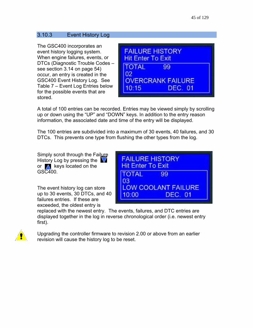
3.10.3 Event Histor ThevW s, D odsee section 3.14 on page 54) occur, an entry is created in the G ry Log. STa Entries bfo ts that arstored. A total of 100 entries can be r g up or down using the “UP” an to the entry reason in iated da Th are subdivide , and 30 D vents one typ Si e FaHistory Log by pressing the or keys located on the G The event history log can storup to 30 events, 30 DTCs, anfailures entries. If these are exceeded, the oldest entry is re trdi n the log i fir Upgrading the controller firmw ision 2.00 or above from an earlier revision will cause the history
y Log
e GSC400 incorporates an ent his ystem. tory logging shen engine failures, eventTCs (Diagnostic Trouble C
or es –
SC400 Event Histo ee elow ble 7 – Event Log
r the possible even e
ecorded. Entries may be viewed simply by scrollind “DOWN” keys. In addition
formation, the assoc te and time of the entry will be displayed.
e 100 entries d into a maximum of 30 events, 40 failurese from flushing the other types from the log. TCs. This pre
mply scroll through th ilure
SC400.
e d 40
placed with the newest ensplayed together i
y. The events, failures, and DTC entries are n reverse chronological order (i.e. newest entry
st).
are to revlog to be reset.

46 of 129
Table 7 – Event Log Entries
An “*” beside the Event Entry indicates the Event is a GSC400 event. All other events are failures (see page section 3.12 on page 52).
Event Entry Description ADC SWITCH FAILURE ADE READ FAILURE ADE WRITE FAIL
These are internal GSC400 failures. Try power cycle the GSC400. If the failure occurs repeatedly the unit could be defected.
AUTO ENABLE* Auto button on front face of controller pressed. GSC400 placed in AUTO mode.
AUXILIARY FAIL The Auxiliary Fail digital input was active. See Table 18 on page 82.
CHARGE OVER* The battery charge run period for low battery is finished and the generator has shut down. See section 4.9.1 on page 84.
CHARGE START* The generator has started up due to low battery voltage. See section 4.9.1 on page 84.
Config Fail 1 Config Fail 2
The Config Fail 1/2 digital input has been triggered. See Table 18 on page 82. The text displayed is the text the user entered from the PC Interface.
EEPROM FAILURE This is an internal GSC400 failure. Try to power cycle the GSC400. If the failure occurs repeatedly the unit could be defected.
EMERGENCY STOP The emergency stop input (located on the digital input terminal) has been activated.
EPS LOADS ERROR AC current sensing indicating that the generator is outputting current when the generator is not running. This could indicate something is wrong with the GSC400. See section 3.12.2 on page 53.
EXERCISER DELAYED TO NEXT RUN*
If the generator was running when it was due for an exercise run. See section 4.7 on page 81
EXERCISER OVER* The exerciser run period is over and the generator has shut down. See section 4.7 on page 81.
EXERCISER START* The generator has started up to exercise itself. See section 4.7 on page 81.
HIGH BATTERY Failure occurred due to high battery voltage. See section 4.9 on page 84.
HIGH ENGINE TEMP Failure occurred due to high engine coolant temperature. See section 4.2 on page 66.
INITIALIZING* EEPROM is being loaded with factory defaults. This occurs on first power up or if the user resets the GSC400 to factory defaults from the PC Interface.

47 of 129
KEY BOARD FAILURE This is an internal GSC400 failure. Try to power cycle the GSC400. If the failure occurs repeatedly the unit could be defected.
LOCKED ROTOR Cranking attempt failed on locked rotor. See section 4.5.1.1 on page 78.
LOG CORRUPTED Event Log corrupted and had to be reset. This usually occurs when power was loss while the event log was being written to. It will also occur when upgrading firmware to version 2.00 or higher from a version below 2.00 for the first time.
LOSS OF ECM COMM J1939 messages required by the GSC400 have not been received. The generator has shut down. See section 4.1 on page 62.
LOW AIR PRESSURE The low air pressure digital input is active. See Table 18 on page 82.
LOW BATTERY Low battery voltage failure. See section 4.2 on page 66.
LOW COOLANT [Level] Low coolant level failure. See Table 18 on page82.
LOW FUEL LEVEL Failure due to low fuel. See section 4.2 on page 66.
LOW HYDRAULIC Low Hydraulic digital input was active. See Table 18 on page 82.
LOW OIL LEVEL See section 4.2 on page 66. LOW OIL PRESSURE See section 4.2 on page 66. MAINTENANCE NEEDED*
The generator requires maintenance. See section 4.11 on page 86.
MAINTENANCE PERFORMED*
Maintenance has been performed on the generator (i.e. the maintenance timer has been reset). See section 4.11 on page 86.
MANUAL START* Generator started manually from the front panel RUN key.
MANUAL STOP* Generator stopped manual from the front panel OFF key.
OFF ENABLE* Front panel OFF key pressed to disable automatic starting.
OPEN ENG TEMP OPEN ENGINE TEMP OPEN FUEL BASIN OPEN FUEL LEVEL OPEN OIL LEVEL OPEN OIL PRES
Analog sender always reads the maximum voltage. Could indicate that the sender is not
connected to the analog input (i.e. broken wire).
OVER CRANK The engine RPM was too high. See section 4.3 on page 71.

48 of 129
OVER CURRENT Over current failure. See section 4.4.3 on page 76.
OVER FREQUENCY Generator Frequency over the failure threshold. See section 4.4.1 on page 72.
OVER SPEED Generator RPM too high. See section 4.3 on page 71.
OVER VOLTAGE Generator voltage high. See section 4.4.2 on page 72.
POWER ON* GSC400 was powered up from unpowered state. REMOTE START* REMOTE STOP*
The GSC400 was started / stopped from the remote start contacts. See section 3.3 on page 35.
RS232 FAILURE RS485 FAILURE
These are internal GSC400 failures. Try power cycle the GSC400. If the failure occurs repeatedly the unit could be defected.
SHORT ENG TEMP SHORT ENGINE TEMP SHORT FUEL BASIN SHORT FUEL LEVEL SHORT OIL LEVEL SHORT OIL PRES
Analog sender reads zero volts or close to zero. This could be caused by a shorted sender.
TLE6230 FAILURE These are internal GSC400 failures. Try power cycle the GSC400. If the failure occurs repeatedly the unit could be defected.
UNDER FREQUENCY The generator frequency is too low. See section 4.4.1 on page 72.
UNDER SPEED The engine speed is too low. See section 4.3 on page 71.
UNDER VOLTAGE The generator output voltage is too low. See section 4.4.2 on page 72.

49 of 129
49 of 129
3.11 GSC400 LED Some industry standard failures, warnings, and events on the GS bseries of LEDs on the left side of the Specific LED indic tors will be
condition of the controller. The
quic f the controcondi The GSC400 displays multi color LED’s for specific condition representation.
Red epresen re C nditions
Yellow
Represen g tions
Green - Represents Normal/Active Conditions
D test may be performed by the user for illumi f all ontroller LED’s. The LED test may rforby simultaneously presand the n the GS 400.
Status Indicators
C400 are indicated y a
controller.
ailluminated depending upon the
GSC400 LED indicators allow a k check o
tion. ller’s
- R ts Failu o
- ts Warnin Condi
An LEnation o c
med be pesing the UP key
DOWN key o C

50 of 129
Table 8 – GSC400 Lamp Indication Meanings
LED LED Color LED Description Status Indication
Over Crank
Red Yellow
Solid Red Solid Yellow
A solid red illuminated LED represents an Over Crank condition on the final crank attempt. This is a Failure. A ts solid yellow illuminated LED represenan ition when Over Crank Warning condthe ining. re are crank attempts still rema
High Eng
Temp
Red Yellow
Solid Red Solid Yellow
A solid red illuminated LED represents a Hi . gh engine Temp Failure condition A resents a solid yellow illuminated LED repHi ion. gh engine Temp Warning condit
Low Oil Press
Red Yellow
Solid Red
A solid red illuminated LED represents a Lo w Oil Pressure Failure condition.
A illuminated LED represents a
Solid Yellow
solid yellowLow Oil Pressure Warning condition.
Over Speed
Red Yellow
Solid Red
A solid red illuminated LED represents an Over Speed Failure condition. A presents solid yellow illuminated LED re
Solid Yellow
an Over Sp g condition. eed Warnin
Low fuel
Red Yellow
Solid Red
Solid Yellow
A solid red illuminated LED represents a Low Fuel Level Failure condition. A solid yellow illuminated LED represents a Low Fuel Level Warning condition.
Battery Status
Green
Yellow
Solid Green Flashing Green Solid Yellow
A solid green illuminated LED represents a normal battery condition. Controller in Auto mode – Waiting to start A solid yellow illuminated LED represents a Low Battery condition.
51 of 129
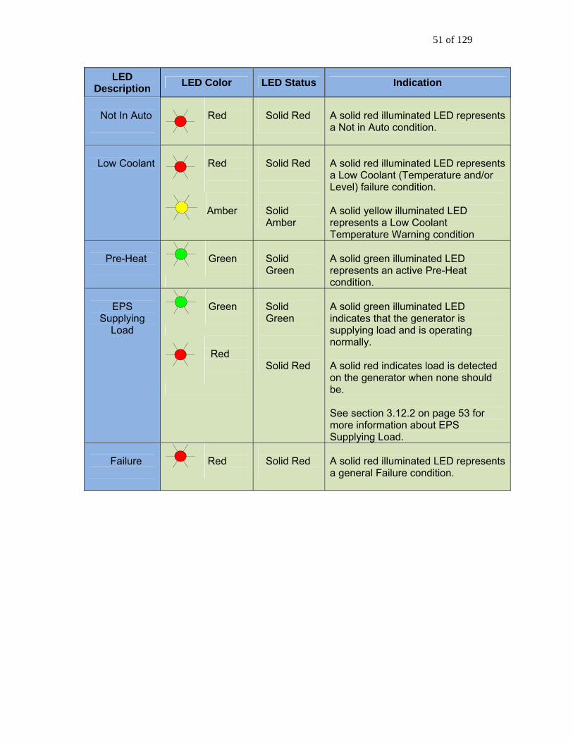
LED Description LED Color LED Status Indication
Not In Auto
Red
Solid Red
A solid red illuminated LED represents a Not in Auto condition.
Low Coolant
Red Amber
Solid Red Solid Amber
A solid red illuminated LED represents a Low Coolant (Temperature and/or Level) failure condition. A solid yellow illuminated LED represents a Low Coolant Temperature Warning condition
Pre-Heat
Green
Solid Green
A solid green illuminated LED represents an active Pre-Heat condition.
EPS
Supplying Load
Green
Red
Solid Green Solid Red
A solid green illuminated LED indicates that the generator is supplying load and is operating normally. A solid red indicates load is detected on the generator when none should be. See section 3.12.2 on page 53 for more information about EPS Supplying Load.
Failure
Red
Solid Red
A solid red illuminated LED represents a general Failure condition.

52 of 129
3.12 Warnings and Failures
The GSC400 incorporates many types of warnings and failures. Most are oactive in the RUN mode while a few are also active in the AUTO and/or OFF modes. Warnings and failures can be triggered from a Switched Input, Analog Input, AC Voltage, AC Current, Speed Signal Input, as well as others. The Advanced Setup section of this manual will give more information of the spwarning and failures for each type of input.
nly
ecific
hen a warning occurs, the second line (the area under the time and date is
O or RUN mode, pressing the Auto key silences the larm while in the OFF mode pressing the Off key performs this function.
e occurs (although most failures only occur in the RUN mode, the ng
r
he failure is recorded in the event log accessible from the Basic menu.
Wdisplay) of the LCD is used to display the warning text. Also, after the warningdisplayed, instructions are displayed showing the user how to silence the warning. When in the AUTa
When a failurLow Fuel Level and Low Coolant Level failures occur in any state includiOFF and AUTO) the controller exits the RUN mode and goes to the FAILURE mode – turning off the Fuel output and other outputs on or off depending on the advanced settings – and displays the failure message. The alarm will sound andremain on until it is silenced by the user. The Auto key can be pressed to silence the alarm. Once the alarm is silenced the controller can be placed into the OFF mode by pressing the Auto key and then the Off key. This returns the controlleto the OFF mode.
T
3.12.1 Diagnostic Trouble Code Shutdowns This section only applies for electronic engines and if the Diagnostic Trouble Code (DTC) feature is enabled. See section 3.14 for more information on DTCs. The GSC400 does not have the ability to detect when the generator ECM has shutdown the generator. In the case of an ECM shutdown the GSC400 will display one of the following failure reasons:
1. Low Oil Pressure 2. Under Speed 3. Under Frequency 4. Under Voltage
The failure message displayed will depend on the user’s failure set points for the above. The user has to check the Event History Log (see section 3.10.3 on page 45 about the history log) to determine if there has been a DTC (DM1) failure sent from the generator ECM.

53 of 129
3.12.2 EPS Supplying Load
e generator when the GSC400 is in GSC400 front panel will
the GSC400 front panel
The GSC400 is often used to control a utility backup generator. When the generator is started and load is detected on ththe RUN mode the “EPS Supplying Load” LED on theturn green. This indicates that the generator is supply load as normal. If load is detected when the generator is not in the RUN mode (e.g. the GSC400 iscranking, preheating, etc) the GSC400 terminates starting and enters the FAILURE mode and the “EPS Supplying Load” LED onwill turn red.
The generator is considered loaded when either the AC current is equal to or greater than 5% of the over current failure setpoint or if the EPS Supplying Load Switched Input is active.
3.13 J1939 This se aparame aonly differenc er can not be read from the J1939 bus the text “N.A.” is displayed in place of the parameter value.
If the Loss of ECM setting is enabled, the GSC400 will shut the generator down on “Loss of ECM” if no communications are detected on the J1939 bus for the param h
ction pplies if J1939 is enabled for one or more parameters. The ters re displayed the same for J1939 as they are for analog inputs. The
e is that when a certain paramet
eters t e GSC400 monitors for.

54 of 129
3.14 J1939 Diagnostic Trouble Code (DTC) Display This section applies for electronic generators only (i.e. generators that use J1939) which have the DTC feature enabled.
The GSC400 can read J1939 diagnostic trouble codes (DTCs) from an electronic ECM, if enabled (see section 4.1.3 on page 64 for information on how to configure and customize the GSC400 DTC feature).
3.14.1 DM1 Messages When ble Code, DM1, message. The DM1 message sent by the ECU will also contain
the engine’s ECM detects a fault, it will send an Active Diagnostic Trou
information on the type of fault as well as the number of occurrences for the fault. If multiple DTCs are present, each will be transmitted over the J1939 network. When the DM1 messages are received by the GSC400 controller there are 3 important pieces of information that are captured and displayed:
FMI Failure Mode Indicator - The type of failure. You must refer to the engine manufacturer’s documentation to identify the meaning of the failure mode indicator number.
OC Occurrence Count
- Identifies the number of times the failure has occurred.
SPN Suspect Parameter Number - The parameter number.
If one of these DTCs appears, please consult your engine manufacture for the efinition of this fault. With some engine manufacturers, the text of the message d
can also vary slightly between engine types. When active DTC messages are being received this will cause the controller display to lock and display the messages. If multiple active DTCs are received the controller will scroll and display each DTC message. The time between scrolling will be 3 seconds. The DTC message display will appear as follows.
Figure 10 – Single Active DTC message

55 of 129
ure 1 messages and the 3PrdP one being displayed
play will begin scrolling though other GSC400 parameters as normal. The DTC messages are no longer available for viewing.
Fig 1 – Five active DTC
The user can also manually cycle through the DTC messages by activating either the "UP" or "DOWN" key after the screen has been locked. If the user stops at a specific DTC message the display screen will remain on that message for a period of 10 seconds before it begins scrolling again. Once the last DTC message is displayed, the dis
3.14.2 DM2 Messages DM2 messages are previously active faults messages which are stored to permanent memory on the engine ECM. These stored messages can be retrieved by the host GSC400 controller and displayed on the controller when a request is initiated by the user. The DM2 messages display the same type of information as the DM1 messages. The GSC400 controller can support a maximum of 32 messages. When previously active DTC messages are requested and received, the GSC400 controller will display the stored messages on the GSC400 front panel LCD screen. If multiple stored messages are received the user can either manually scroll through each stored message or the screen will scroll between each DTC stored message at a 3 second interval. If the user intervenes, the interval will change to 10s. The DTC stored message display appears as follows:
Figure 12 – 32 stored DTC messages, the 5PthP stored code being displayed

56 of 129
To Trigger a DM2 Request, simultaneously press the "UP" and "DOWN" keys for a period of 3 seconds in either the AUTO, OFF, or RUNNING modes. The controller’s alarm will sound and the controller will send a request to the ECM. A LAMP test will additionally be triggered in the OFF mode. The “UP” and “DOWN” keys can also be pressed to remove the DM2 message screen.
If the GSC400 is in the OFF or AUTO mode when the request is triggered, the ECM may not be powered on, so the controller will energize the fuel relay output and wait for the ECM to power on. The GSC400 then sends out the DM2 request. In the event there is no response from the ECM, the controller will re-attempt an additional 3 times every 1.25 seconds. It will then display "REQUESTING FAIL" and turn off the fuel output if there is no valid response on the fourth try. The default ECM address for DM2 request is 0 and the ECM address can only be changed from the GSC400 PC interface. The GSC400 may also show "READING ABORT..." if communication is unsuccessful. If the request was successful, the GSC400 will show "READ DTC SUCCESS" and start to display the messages. 3.14.3 DM1 Event Log: The GSC400 Event Log (see section 3.10.3 on page 45) can store up to 30 DM1 messages (DM2 messages are not stored). Once the 30 limit has been reached the oldest message is removed from the log to be replaced by the incoming DM1. All entries in the log are stored in a reverse chronological order with the most recent event displayed first.

57 of 129
This page intentionally left blank.

58 of 129
4. Advanced Setup This section will explain the Advanced Menu of the GSC400.
4.1 J1939 Setup .................................................................................................... 62 4.1.1 Auto Power ECM ........................................................................................ 64 4.1.2 Cummins Idle Speed ................................................................................. 64 4.1.3 Diagnostic Trouble Codes (DTCs)........................................................... 64
4.2 Analog Inputs .................................................................................................. 66 4.2.1 Fuel Level Sender – Special Case .......................................................... 68
.............. 68 ...................................... 69
..................................................................... 71 ....................................................................... 71 ent / Frequency) Setup .............................. 72
................................................................... 72 ........................................................................ 72
75 ................................................................... 76
tion ........................................................ 76 .................................................................. 77
quence ...................................................................................... 77 4.5.1.1 Locked Rotor................................................................................... 78
........................................................................... 78 rable Outputs) Setup ............................................. 79
81 witched Inputs) Setup .................................. 82
.............................................................................. 84 ......................................................................... 84
.................................................................. 85 4.11 Set Maintain .................................................................................................... 86 4.12 Set Modbus ..................................................................................................... 86 4.13 Common Faults .............................................................................................. 86 4.14 Set Dummy Load............................................................................................ 87
4.2.2 Electronic Sensors – 0 to 5VDC ................................................4.2.3 GSC400 Sender Support ....................................
4.3 Speed Sensing ..........................4.3.1 Rated Speed ........................
4.4 Generator (AC Voltage / Curr4.4.1 AC Frequency ..........................4.4.2 AC Voltage ..........................
4.4.2.1 Voltage Select Inputs.....................................................................4.4.3 AC Current................................4.4.4 AC Current and Voltage Calibra
4.5 Engine Logic .................................4.5.1 Startup Se
4.5.2 Shutdown Sequence.......4.6 Digital Output (Configu4.7 Exerciser Setup ..............................................................................................4.8 Digital Input (Configurable S4.9 Battery Setup ....................
4.9.1 Low Battery Recharge ......4.10 Password Setup ...........................

59 of 129
The GSC400 incorporates an Advance r knowledgeable users should change th Before entering the Advanced menu a password is required. The password consists of a four digit number. Each number needs to be selected using the up or down arrows on the GSC400. Simply choose the correct password number for each selected position by scrolling to the proper number followed by the Enter key. The default passworis 0 0 0 0. The password may be changed anytime. Se Setupsection on page 85.
The Advanced Setup menu on the GSC400 is shown to
See Table 9 below for a list of the various submenus in the Advancmenu and a descripAppendix A on page 88 lists the various submenus, the settings they contain, and the range of each setting.
d Setup menu. Only OEMs oese parameters.
d
e Password
the right.
ed tion of each.
Important! ersions Below 2.00 ler, the controller needs to be rese
For Firmware VAfter changing any settings on the control t. This can be done one of two ways:
1. Power off, r o2. Press the Run key, w t until the co and then
press the OFF key. You will see a er u
wait for 2s, and powe n the controller. ai ntroller begins the start sequence
flickering of the screen as the controllpdates.

60 of 129
Table 9 – Advanced Menu Layout Summary
Menu Layout Description
J1939 Setup
The J1939 setup contains general settings for J1939 such as shutdown on loss of messages. To read parameters from the J1939 bus please see “Analog Inputs” below.
High Engine Temp
Oil Pressure
Fuel Level
Oil Level
Fuel In Basin
Low Engine Tmp
Analog Inputs: These control all aspects of the specific analog input listed in the left column such as whether it is a switch, sender, or obtained from J1939. You can also set the input you want it to connect to. The warnings and failures as well as open and shorted sender detection shutdowns are also configurable.
Speed Sensing
The speed sensing source (magnetic pickup, generator voltage, J1939), under and over speed warnings and failures.
AC Frequency
The crank disconnect frequency and the over/under frequency warning/failures.
AC Voltage
The AC voltage sensing/display is contained here as well as the over and under voltage warnings and failures.
AC Current
The CT ratio, AC current sensing and display enable are contained in this menu.
Engine Logic
All the basic start and shutdown logic are contained in this menu.
Outputs Setup
This menu allows you to assign a feature/action to one of eight digital outputs. For example you can turn on a digital output when an under-speed failure occurs.
Exerciser Set
Generators require periodic operation as part of their scheduled maintenance. This menu allows settings to control how often the engine/generator is started and for how long.
Advanced Menu (Password Protected)
Inputs Setup
This menu allows you to assign features/warnings, for example low oil pressure, to one of eight digital

61 of 129
inputs.
Battery Setup
This menu controls the settings for the battery under and over voltage warnings and failures. It also allows the user to set at what battery voltage to start the generator and how long the generator is to remain running.
Set Password
The advanced menu requires a password for access. The user can change the password here. The default password is 0000.
Set Maintain
This menu controls the service notification feature for regular maintenance. The user can enable/disable the feature and set the service interval. A technician can reset the service interval here. On reset the service counts down to the next service.
Set Modbus
This sets the modbus slave address and baud rate.
Common Faults
The user can select a group of failures, warnings, t a hand events twhen triggered will cause a digital output to turn on. Th o e user alsneeds to select thi s feature in thedigital outputs menu for one of the outputs.
Set Dummy Load
This contains the logic to turn on and off a digital output to place an additional load on a generator. The user can select the switch-on and switch-off current thresholds.
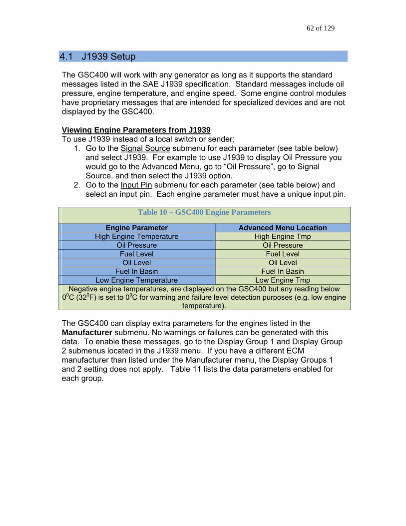
62 of 129
4.1 J1939 The GSC400 will work with any generator as long as it supports the standard me in the SAE tion. Standard de oil pressure, engine temperat eed. Som es hav message for specia ot displayed by the GSC400. View Paramet
Setup
ssages listed J1939 specifica messages incluure, and engine sp e engine control modul
e proprietary s that are intended lized devices and are n
ing Engine ers from J1939 To use J1939 instead of a local switch or sender:
1. Go to the Signal Source submenu for eeach parameter (see table below)
and select J1939. F J1939 to to the Adva to “Oil Press
Source, and then select the J1939 option. 2. Go to the Input Pin
or example to usnce go
display Oil Pressure youwould go d Menu, ure”, go to Signal
submenu for each parameter (see table below) and n input pin. E meter mu .
select a ach engine para st pin have a unique input
Table ine Paramet 10 – GSC400 Eng ers
Engine Parameter Advanced Menu Location High Engine Temperature High Engine Tmp
Oil Pressure Oil Pressure Fuel Level Fuel Level Oil Level Oil Level
Fuel In Basin Fuel In Basin Low Engine Temperature Low Engine Tmp
Negative engine temperatures, are displayed on the GSC400 but any reading below 00C (320F) is set to 00C for warning and failure level detection purposes (e.g. low engine
temperature). The GSC400 can display extra parameters for the engines listed in the
submenu. No warnings or faManufacturer ilures can be generated with this to the Display Group 1 and Display Group data. To enable these messages, go
2 submenus located in the J1939 menu. If you have a different ECM manufacturer than listed under the Manufacturer menu, the Display Groups 1 and 2 setting does not apply. Table 11 lists the data parameters enabled for each group.

63 of 129
Table 11 – J1939 Addition Parameter Display Options.
Engine Manufacturer
Display Group 1
Display Group 2
John Deere Engine Torque (%) Friction Torque (%)
Load (%)
Intake Temperature (0C) Fuel Temperature (0C)
Fuel Rate (L/min)
Volvo Penta Engine Torque (%) Friction Torque (%)
Load (%)
Boost Pressure (kPa) Oil Temperature (0C)
Fuel Rate (L/min) Set Speed (RPM) ECM Battery (V)
Load (%) Cummins
Fuel Rate (L/min.)
Barometric Pressure (kPa) Fuel Temperature (0C) Oil Temperature (0C)
Yanmar
Set Speed (RPM) ECM Battery (V)
Load (%) Fuel Rate (L/min.)
Barometric Pressure (kPa) Fuel Temperature (0C) Oil Temperature (0C)
Detroit Diesel Engine Torque (%) Friction Torque (%)
Boost Pressure (kPa) Oil Temperature (0C)
Load (%) Fuel Rate (L/min)
Others - Select this is your engine is not No Display No Display
listed above. Loss of ECM Setting There is also a Loss of ECM submenu in the J1939 menu that you should enable using J1939. When enabled, the controller will shut down on a failure
en received on the CAN bus for ifwhen certain J1939 messages have not bepproximately 6 seconds. a
Parameter Display – Special Case Also, when there has been no data received for a specific parameter, that parameter will display “N/A” in place of the value. This will disappear once data for the parameter is received from the bus. This will also occur on startup until the GSC400 accesses the data from the bus. Note that loss of ECM may ot be triggered since other parameters may be receiving data from the bus.
p Delay
n ECM Boot-u
are first powered. Ensure that the crank t count. If extended cranking is not desired the glowplug (preheat) time can be set to turn on the fuel relay for a set time before cranking begins. Ensure that no output is set to preheat. Another ption is to Auto Power ECM setting. This allows the fuel relay to
See the next section below.
ECMs can take up to 10s to bootup when theyime is long enough to take this into ac
oremain on in the AUTO mode.
enable the

64 of 129
4.1.1 Auto Power ECM Some ignificant time to power up and initializ e engine. The GSC400 can be programmed to leave the fuel relay output on while in the AUTO mode by enabling A M. This will ensure the ECM is already powered up and ready to go when the user desires to start the generator. When the ontroller exits from the RUN mode the ECM Power Delay setting controls the
rator from starting up unexpectedly if it hasn’t fully shut down hen the controller entered the Auto mode.
Engine Control Modules (ECMs) require se before they are ready to control th
uto Power EC
camount of time the GSC400 waits before turning on the fuel output. This is done to prevent the genew 4.1.2 Cummins Idle Speed The GSC400 can switch between idle and normal operating speed on Cummins generators. When the fuel relay is on, the GSC400 continuously sends out a speed command every 250ms to tell the generator which of the two speeds to run at. A configurable switched input must be set to Idle Mode (see Table 18 on age 82) and when this switched input is active the generator runs at idle speed;
ture set Cummins Idle to GCP Enable or GC1 Enable. GC1 is e newest protocol while for older engines you will need to use GCP.
“J1939 Erratic”. The ECM expects the speed update to be sent continuously and if it is not the ECM thinks there is a problem with the J1939 communications.
potherwise it runs at normal operating speed. To enable this feath If you are powering the ECM externally you may get an error message (if Cummings Idle Speed and Diagnostic Trouble Codes are enabled – see below),
4.1.3 Diagnostic Trouble Codes (DTCs) The GSC400 has a DTC feature that, when enabled, allows the controller to receive currently active DTCs (DM1) messages and display then on the screen as well as optionally store then to the Event Log. The controller can also receive previously active (DM2) messages and display them on command. DM2 messages are intended for technician troubleshooting and are not stored to the Event Log. The GSC400 supports the following J1939 standards when reading DM1 messages:
1. Single package frame J1939-71 2. Multi-packages frame J1939-21
a. BAM b. TP.DP

65 of 129
The GSC400 supports thessages:
e following J1939 standards when reading DM2
S
The TC feature and configure its behavior with the
ll
s.
disables the storing of active faults g reserves 30 storage locations for
ored hen this setting is enabled the GSC400 will
.
m1. DM2single package frame J1939-71
39-21 2. Multi-package frame J19a. BAM
CTb. RTS/DPc. TP.
user can enable/disable the Dowing settings. fo
DTC DISPLAY – This setting enables or disables active fault messages (DM1) monitoring. When the DTC DISPLAY feature is enabled the GSC400 can receive active faults in the RUNNING, OFF and AUTO modes on the J1939 buAny new received active faults will trigger a message "NEW ACTIVE DTC" and the user can read the message on the GSC400 front panel display. This new message will also be stored into the controller’s event log if this feature was enabled. ACTIVE LOG DTC - The setting enables/DM1) in GSC400 Event Log. The Event Lo(
DM1 messages. READ STORED DTC – The setting enables/disables the ability to request stault codes from the ECM (DM2). Wfallow manually triggered requests of stored faults from the ECM’s memory (DM2)

66 of 129
4.2 Analog Inputs The GSC400 has support for the following analog input types:
1. High Engine Temperature1 2. Oil Pressure 3. Fuel Level 4. Oil Level 5. Fuel In Basin
f a
6. Low Engine Temperature2 For each of the analog input types, you can select the pin (2 to 7) to connect to inthe Input Pin menu. See Figure 4 on page 12 for the pin locations of the analog input connector. If you are not using one of the inputs indicated then select
isabled. Also, you must select a pin even if you are using J1939 instead oDphysical sender or switch. Two different analog types cannot share the same pinwith the exception of the Low Engine Temperature and High Engine Temperatureas this allows the use of one sender for both low engine temperature and high engine temperature. Attaching Switches to the Sender Inputs
The user has the option of connecting either senders or switches to the analog inputs. If using switches they must be switched to ground but can be either normally open or normally closed. Set the “Signal Source” menu to “Switch Input” and the “Switch Setting” menu to “Closed = Fail” for normally open switches or “Open = Fail” for normally closed switches. If the Input Type is set to a switch in the RUN mode (see section 3.4 on page 37) the controller will display “SW” in place of the value that would be displayed if it was set to J1939 or Sender. When the switch becomes active the controller will shutdown the engine with the excep n r tio of Fuel Level for which you can set the controller to either shutdown ogenerate a warning.
1 Negative engine temperatures, can be displayed on the GSC400 but any reading below 00C (320F) is set00C for warning and
to failure level detection purposes (e.g. low engine temperature, high engine
temperature). 2Same as (1) above.

67 of 129
In addition, you must select the Input Type, such as sender, J1939, or switch (see the section below for more information on senders). The factory default ender tables loaded in the GSC400 only support pins 3 and 4. If you need
Utility. Refer information about the utility.
s
riod, if there are any warnings or failures they will be r
sto use other pins, you must use the GSC400 PC Interface Sendero the GSC400 PC Interface manual for moret A Bypass Time can be selected for each input (this applies to J1939, senders,and switches). After crank success, the bypass period will start, and during thiperiod the controller will not enable the warning or failure checks for this input.
fter the bypass peAt iggered. The controller will display a message and sound the alarm in the case f a warning or will shut down and sound the alarm in the case of a failure. o
Warnings and Failures – J1939 or Senders: Each of the analog types supports
lue must drop below
Warnings and/or Failures. In the case of high engine temperature, if the data from the sender (or J1939) exceeds the value set, then the controller will give a
arning or failure. For the other analog input types, the vawthe warning and/or failure setting. Warnings and failure thresholds are only supported when using senders or J1939. The Low Oil Level and Fuel In Basin warnings are global meaning they are always active even in the OFF state.
he warnings for these also ignore the Bypass Time. T Warnings and Failures – Switch: Except for a couple of cases when set to a switch the GSC400 will shutdown if the switch becomes active. The cases wherehis does no
t happen are:
1. Fuel Level t
– The fuel level can be set to warn or fail (shutdown) if the switch becomes active. This is controlled in the Switched Setting submenu of the Fuel Level menu.
2. Low Engine Temperature – When the switch becomes active, the GSC400 generates a warning only. No failure setting is possible.
If you have the Input Type as a sender then you also need to set the Open Sender Detection or Shorted Sender Detection to Warning, Failure, or Disable. The Open Sender Detection will trigger if the analog input voltage rises above 4.76V. The Shorted Sender Detection will trigger if the voltage drops below 0.122V.
Input Pin Disable Note
itch setting is set to “Closed = Fail”. This effectively disables the input. If changing the source, ensure
When the Input Pin is set to disabled it is actually set to a virtual input where the
voltage read is 5V, the signal source is set to a switch, and the sw
that the Input Pin is not set to disabled.

68 of 129
4.2.1 Fuel Level Sender – Special Case You will need to know the resistance of the sender at 0%, 25%, 75%, and 100%
.g.
are version can be found on the back label contained in the
fuel levels. The resistance values must be either monotonically increasing (e1, 2, 3, 4, 5) or monotonically decreasing (e.g. 5, 4, 3, 2, 1). In the Fuel Level menu (located in the Advanced Setup menu) you will also need to set the controller type or hardware version (LS/LX, or LSB/LXB). The ontroller hardwc
product number (under the bar code). Section 1.4 on page 12 explains how to read the product number. 4.2.2 Electronic Sensors – 0 to 5VDC If you have an electronic sender that outputs a voltage between 0 and 5VDC you can use it on the GSC400. You must convert the voltage output to a
rresponding resistance so you can enter it in the menu. To do this, use the following formula:
Resistance = (Voltage Output x esistance) / (5 – Voltage Output) Where: Voltage Output
co
Pull-up R
– rea t of the fuel sender P ance
the voltage d at the outpuull-up Resist – in Ohms and depends on the analog input. It is 1000 Ohms
d Oh 6, O d 6 he full ra of the sende e other inpu ve a gain of three which will multiply the analog signal of the electronic sender three times thus limiting it to the range 0V to 1.33V. It is recommended to use pin 6 because its 5.11k Ohm pull-up will have less of an effect on the v t of t ic send the 1k O of pin 2.
for pins 2, 3, an
nly pins 2 an
4; and 5110 ms for pins 4, and 7.
will give t nge r. Th ts ha
oltage outpu he electron er than hm pull-up

69 of 129
4.2.3 GSC400 Sender Support Temperature Senders Note Temperature senders often do not read low temperatures. The temperature range of the sender that Dynagen stocks is 1300F to 3300F. If the temperature iselow 1300F the controller will d
isplay 1300F. If the temperature is above 3300F
0
to the
ference and to provide more information to allow the user to determine which sender to use. Refer to the PC Interface manual.
bthe controller will display 330 F. The same behavior applies to other sender types as well. In the Signal Source submenu in each of the six analog input menus there is a selection of three preloaded sender tables from which to choose in addition “J1939 Input” and “Switch Input” choices. The sender tables that are preloaded into the controller are given in Table 12. The PC Interface Sender Utility name for versions 1.8.1 and above are shown for re
Table 12 – Default Sender Tables
Signal Source Sender 1 Sender 2 Sender 3 Front Panel Menu Name Datcon 1 VDO 2 Murphy 1 Sender Utility
Name Datcon 330F
491Ohm VDO 266F 488Ohm
Murphy 368F 488Ohm
Sender Part Number**
Datcon 2022-00, 02024-00, and 02025-00
VDO 323-421 Murphy ES2T 250/300
Resistance Type Low Low Low
High Engine Temperature / Low Engine Temperature
Supported Analog Input
Pins* 3, 4 3, 4 3, 4
Front Panel Menu Name Datcon 1 VDO 1 Murphy 1 Sender Utility
Name Datcon 99PSI
241Ohm VDO 99PSI
136Ohm Murphy 99PSI
237Ohm
Sender Part Number**, ***
Datcon 2505-00 / STEWART &
WARNER 279B-F
VDO 360-004 Murphy ESP-100
Resistance Type Low Low Low
Oil Pressure
Supported Analog Input
Pins* 3, 4 3, 4 3, 4
* For LSB/LXB controllers. For LS/LX controllers pin 2 can also be used. ** Some senders can be supplied by Dynagen. Refer to Table 25 – Senders Part List on page 103 for the Dynagen stock code. ***Datcon 2505-00 (ACC0074) replaced by STEWART & WARNER 279B-F (ACC0108) which is drop in replacement.
70 of 129
he six analog input pins aT re divided into two groups: those that support low
Ohms s
Note threason also lists what sender tables ma a sconfiguender put you desire. Refer to the C
resistance senders and those that support high resistance senders. Low resistance senders have a maximum resistance of less or equal to 500 Ohms.
igh resistance senders have a maximum resistance of greater than 500H(u ually they are a few kOhm).
at the senders listed in Table 12 cannot be used on all outputs (for the given in the previous paragraph). Table 12s
y be loaded on each input. If your sender is not supported or you wish to useender on an unsupported input then you have to use the sender table
ration utility built into the PC Interface that allows you to create new tables or to modify supported ones for the ins
P Interface manual for more information.

71 of 129
4.3 Speed Sensing The speed sensing menu allows you to select the source to use for sensing the rotational speed of the engine. There are three options to choose from:
1. J1939 Input – If the engine/generator comes equipped with an engine GSC400
tput – The GSC400 can also determine the engine speed e source of the
SPEED 2 terminals.
Ofailures can be set from arnings and failures
ove.
control module (ECM) that supports the J1939 protocol then the can obtain the engine speed from the ECM.
2. Magnetic Pickup – If the engine/generator is equipped with a magnetic pickup sensor then the sensor can be connected to the SPEED 1 and SPEED 2 spade terminals on the GSC400.
3. Generator Ou
indirectly from the generator frequency. The voltaggenerator must be connected to the SPEED 1 and
ver-speed warnings and failures as well as under-speed warnings and the menu in units of RPM. The w
apply to all three options ab
4.3.1 Rated Speed For the magnetic pickup and generator output options you must select trated frequency and rated speed. The GSC400 uses these values togethercalculate the engine speed from the magnetic input or genera
he to
tor output.
the engine runs t when producing powe
others run at 3600RPM. The is usugene prodfrequency is determined by the d by:
uency For the generator output optithe generator: 50Hz or 60Hz.
The rated speed is the speed (in revolutions per minute, RPM)a r. For example some generators run at 1800RPM while
rated frequency rator output when
ally either 50Hz or 60Hz. It is the frequency of the ucing power. For a magnetic input the rated
number of teeth on the flywheel and is calculate
Rated freq = (Number of teeth x Rated Speed) / 60 on the rated frequency is normally the frequency of

72 of 129
4.4 Generator (AC Voltage / Current / Frequency) Setup
t The AC Frequency, AC Voltage, and AC Current menus allow the measuremenand display of the AC voltage, current, and frequency from the generator. 4.4.1 AC Frequency
ting d input. If the speed
put is not detected, the controller checks the DisconnectFreq settings. If the meconsidered running.
In the AC Frequency menu, warnings and failures can be triggered for frequencies under and/or over settable thresholds. The DisconnectFreq setis used by the GSC400 controller as a backup to the speein
asured frequency is greater than this setting then the engine will be
4.4.2 AC Voltage This section will cover the configuration of AC Voltage.
ro
Note that the GSC400 requires a neutral reference f m the generator and can only support up to 60 AC L-L0V .
GSC400 Voltage Groups
ente oltage, and ove c e 15 below).
pro identical se o betor types o support mu ltag
single generator without having to go into the menu syste
the o all voltage groups.
The user can different voltagGSC400 unitsgenera
r under voltage, over vonfigurations (see Tablgrammed withr a GSC400 to
er curre r four This allows multiple used on multiple e configurations on a
m.
nt settings fo
ttings tltiple vo
Table 13 lists
submenus that apply t
Table 13 – AC Voltage Submenus
Submenu Description Voltage Source Enable or Disable Voltage Sensing. Note AC Current
Sensing will not work without voltage sensing enabled.
Line or Neutral This only affects how the AC . Voltage is displayedThe choices a to Lre “Line ine”, “Line to Neutral”, or
“Both”. Voltage Group This is where the user picks wh to ich voltage group
use (1, 2, 3, or 4). There are other s three listed here but they apply to specific ubmenus under thevoltage groups. See Table 15 below.

73 of 129
Selecting a Voltage Group to Use The Volta one or two digital inputs can be used to determine the voltage group to be used. See
4.2 al inputs overrid Group
ing GSC ar Gen
ge Group submenu can be used for this purpose. Alternatively
section 4.submenu.
.1 below. Note that the digit e the Voltage
Configur 400 for a particul Set Configuration Each voltage grou r more generator configurations given in Table 14. Three of the voltage groups have an option to support one genset configuration over in the fo
p applies to one o
another as seen urth column.
Table 14 – GenS and How to Configure Them in the GSC400 et Configurations
Refer to Figure 6 on page 26 for a diagram of each of the various three phase configurations.
GenSet Configuration Description
Voltage Groups
SupportedGroup 1, 3, 4 Setting
Single Phase – 2 wire
The GSC400 display is fixed to L-N. 1 Set Group 1 Setting to “2
wire single” Single Phase – 3 wire
1 Set Group 1 Setting to “3 wire single”
Three Phase Ungrounded Delta
No neutral reference. Use of 1:1 transformers required.
2, 3, 4
If using Group 3 set Group 3 option to “Normal
Voltage”. If using Group 4 set Group 4 option to
“Three Phase”. Three Phase Center Grounded Delta (rare)
One of the corners is used for neutral reference. Phase C on GSC400 is the “stinger” high leg.
4 Set Group 4 Setting to “Four Wire Delta”
Three Phase Center Grounded Wye
Neutral reference taken from where three windings come together.
2, 3, 4
If using Group 3 set Group 3 option to “Normal
Voltage”. If using Group 4 set Group 4 option to
“Three Phase”. Three Phase Center Grounded Wye, Voltage Sensing Center Tapped (rare)
The voltage sensing for the GSC400 is taken from the midpoint of each of the three windings. Reduces voltage to controller by ½.
3 Set Group 3 option to “2 Times Voltage”.
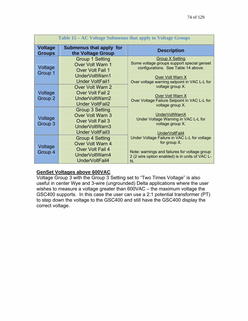
74 of 129
Table 15 – AC Voltage Submenus that apply to Voltage Groups
Voltage Groups
Submenus that apply for the Voltage Group Description
Voltage Group 1
Group 1 Setting Over Volt Warn 1 Over Volt Fail 1 UnderVoltWarn1 Under VoltFail1
Voltage Group 2
Over Volt Warn 2 Over Volt Fail 2 UnderVoltWarn2 Under VoltFail2
Voltage Group 3
Group 3 Setting Over Volt Warn 3 Over Volt Fail 3 UnderVoltWarn3 Under VoltFail3
Voltage Group 4
Group 4 Setting Over Volt Warn 4 Over Volt Fail 4 UnderVoltWarn4 UnderVoltFail4
Group X Setting Some voltage groups support special genset
configurations. See Table 14 above.
Over Volt Warn X Over voltage warning setpoint in VAC L-L for
voltage group X.
Over Volt Warn X Over Voltage Failure Setpoint in VAC L-L for
voltage group X.
UnderVoltWarnX Und nin er Voltage War g in VAC L-L for
voltage group X.
UnderVoltFail4 Under in VA oltage Voltage Failure C L-L for v
for group X.
Note: warnings and failures for voltage group 2 (2 wire option enabled) is in units of VAC L-N.
GenSet Voltages above 600VAC Voltage Group 3 with the Group 3 Setting set to “Two Times Voltage” is also use ser wis the GS use a 2:1 potential transformer (PT) to s the cor
ful in center Wye and 3-wire (ungrounded) Delta applications where the uhes to measure a voltage greater than 600VAC – the maximum voltage
400 supports. In this case the user canCtep down the voltage to the GSC400 and still have the GSC400 displayrect voltage.

75 of 129
4.4.2.1 Voltage Select Inputs
splay as well as arning/shutdown trip points relating to AC voltages and currents. This is useful
It is possible to automatically choose a voltage configuration by setting one or two of the digital inputs to Volt Select 1 and Volt Select 2. This allows the GSC400 to automatically re-configure its voltage diwfor mobile generators where the voltage selections can be selected via a CAM switch. Warning: The Voltage Select Inputs override the Voltage Group submenu parameter in the AC Voltage menu.
Table 16 Voltage Select Inputs
Digital Inputs Voltage Configuration Volt Select 1 Volt Select 2 Voltage Group 1 (Single Phase)
1 Phase, 3-wire (2-wire option also selectable)
Open Circuit Open Circuit
Voltage Group 2 3 Phase, 4-wire Wye, ungrounded delta
ACTIVE Open Circuit
Voltage Group 3 3 Phase, 4-wire Wye, ungrounded Delta
(2x display voltage option also selectable)
Open Circuit ACTIVE
Voltage Group 4 3 Phase, 4-wire Wye, ungrounded Delta
(4-wire, corner grounded, Delta option also selectable)
ACTIVE ACTIVE
If Digital Input Pin A, B, C or D is used, then ACTIVE is defined as a switched to +BAT connection. If Digital Input Pin E, F, G or H is used, then ACTIVE is defined as a switched to GND connection. NOTE: If only a single AC Group Sel function is selected, then the remaining unassigned AC Group Sel is equivalent to an “Open Circuit” in the above table.

76 of 129
4.4.3 AC Current The GSC400 controller is designed to measure AC current from the generawith the use of current transformers (CTs). The maximum current on the AC current terminals of the GSC400 is lim
tor
ited to 5A.
is
rn, means the GSC400 displays 1000A on the screen when the current
he AC Current menu is also used to set the over current warnings and ed in terms of the voltage group 1 to 4. The AC
urrent warning and failure depends on the voltage group selected in the Voltage
he Hi Wye Current parameter (second to last entry in the AC Current menu) is the
from each phase.
h
for Unlatch”.
The “Turns Ratio” sub menu is used to setup the CT ratio. All numbers in thmenu are in terms of 5A. For example selecting 1000 means 1000:5A which, in tumeasured on the GSC400 AC Current terminals is 5A. The GSC400 current terminals can handle a maximum of 5A. Larger currents can damage the GSC400. Tshutdowns. These are groupcGroup submenu of the AC Voltage menu. Tused to double the current reading (50% selection). If this is not desired then 100% selection should be selected. Some generators have two wires for each phase, and as such, the current transformer (which is placed on only one lead) will see only 50% of the current The Cur Warn Latch option (last entry in the AC Current menu) is used to latcon a special digital output (see Current Latch in Table 17 on page 79) that turns on when the current exceeds the Current Warning Threshold and can only beturned off by the user at the front panel. On a current latch condition the LCD displays “Over Current Latched.” and “<Up Arrow> + <Down Arrow> The current transformers (CTs) negative leads must be terminated individually into the GSC400 AC Current connector. Do not tie the negative leads together to a common neutral. See the system wiring diagram (Figure 4 on page 17) for more details. 4.4.4 AC Current and Voltage Calibration
ach GSC400 undeE rgoes an advanced two point calibration at the factory and
ith a high total harmonic distortion (THD).
typically does not required calibration except in the following instances: 1. Current Transformers (CT) are used that have poor tolerances. 2. The uncommon occurrence where the AC signal from the generator is
distorted w DynaGen has a software utility that can perform a basic calibration of the current and voltage.

77 of 129
4.5 Engine Logic
he Crank Disconnect setting determines the speed that must be attained
ure
.5.1.1 on Locked Rotor).
The Engine Logic menu contains the settings that control the starting and stopping of the engine. All parameters in bold below are located in the enginelogic menu unless otherwise noted. Tbefore the crank output is turned off and the genset is considered to be running. The Crank Oil Pressure parameter is used to determine when to check for the Locked Rotor condition. If the oil pressure is lower than the Crank Oil Pressthe GSC400 will check the engine speed for a locked rotor condition (see section 4 4.5.1 Startup Sequence All parameters in bold below are located in the engine logic menu unless otherwise noted. When performing an automatic or manual start, the controller will wait for the Delay To Start duration and then turn on the glow plug output for the Preheat (glow plug) duration. The fuel output is also turned on. (Note: preheat and glow
ning.) plug have the same mea Normally the fuel remains off in the AUTO mode until Preheat is entered. For electronic engines some applications require that the ECM (usually powered by the Fuel Relay output) to be powered in the AUTO mode in order to start the generator as quick as possible. The J1939 menu has settings to allow the fuel output to turn on in the AUTO mode. See section 4.1.1 on page 64. After the preheat (glow plug) time, the crank output is turned on for the duration specified by the Crank Time. If the engine speed does not go above the Crank Disconnect Setting before the crank time then the crank output is turnedoff and the controller waits a period specified by the Crank Rest Time. The locked rotor condition is also checked while cranking (see 4.5.1.1 Locked Rotor
RING THE FIRST 2 SECONDS OF CRANKING EFFECT ON THE CONTROLLER DURING
below). The fuel output is also turned off unless the “Fuel On During Crank Reset” is enabled. THE LCD WILL TURN OFF DU
AGE DIPTO LIMIT THE VOLTCRANKING. If the Midheat Time is greater than zero, the glow plug output remains on during cranking but not during crank rest. The glow plug output turns off if a crank failure occurs, once crank success is reached (unless the PostHeat is set to a value greater than 0s), or if the Midheat time expires.

78 of 129
After the crank rest delay expires, the controller turns on the fuel and crank utputs and attempts to start the generator again. This is repeated until the
r cannot start the enerator after the set number of crank attempts, the failure state is entered and
abled then the engine speed is monitored for 10 seconds. If the engine
peed goes below the crank disconnect speed the controller attempts to restart the engine/generato seconds the engine will go into the OFF mode without cooling down (if cool down is enabled).
e time, if the W a digital output can be set be set to “Warm Up”) whany load or potential loadtime the output remains
Once the controller ente ater than 0, the glow plug out n of the PostHeat time.
onumber of tries equals the Crank Attempts. If the controllegan over crank failure is displayed on the screen. If the generator starts successfully and the “Restart on False Start” submenu isset to Ens
r. If the Off key is pressed during these 10
At the sam arm-up sub menu is set to a value greater than zero,
to turn on (one of the digital outputs or Extra relay must en the warm-up is finished. This is used to disengage s until the gen-set is warmed up. During the Warm-up
off.
rs the Running state and if the PostHeat time is greput is turned on for the duratio
4.5.1.1 Locked Rotor
r is a safety/g r input. To disable this fea
The Crank Os cranking.
the oil c ngine
shortened to 3s (including the time passiscon ure at the
end of the 3s the GSC40 re.
its damag ngine crankshaft (generator ro
Locked roto enset protection feature using the oil pressure sendeture set the Crank Oil Pressure in the engine logic il Pressure is the lowest normal omenu to 0.
the engine iil pressure seen while
gine logiDuring cranking if menu) and if the e
pressure is below the Crank Oil Pressure (enspeed and AC frequency are both 0 the crank time is
ed in cranking). If the genset has not reached the crank d nect speed, frequency or the Crank Oil Press
0 will stop cranking and go into a Locked Rotor Failu
This feature lim e to the generator if something is preventing the etor) from rotating.
4.5.2 Shutdown Seque
s pre is l de
l Dow con
set to a value greater than 0 seconds an
nce When the OFF key i ssed while the engine/generator is running and if the
set to a value greater than 0 seconds the Cool-Down submenugo into Cool Down mo
generator wil where an output is turned on (one of the digital outputs
must be set to Coois turned off and the
n). Once the Cool Down time has expired, the fuel relay troller enters the OFF mode. If the ETS On Duration is
output will be turned on for the time set

79 of 129
(one of the configurable 4.6 on page 79) by the E
outputs must be set to “Energize-to-Stop” – see section TS On Duration submenu.
4.6 Digital Output (C
A dry contac h Table 1 le
onfigurable Outputs) Setup There are eight 200mdigital output (d
igital outputs (all switched to ground) and one 40A t), the Extra output, all of which are configurable. Eac
feature (listed inoutput.
7 below) is permitted to be set to only one configurab
Table 17 – Configurable Output Selections
Name Description Warm Up This sets up the output to be controlled by the Warm-up
feature. See section 4.5.1 for more details. The Warm-up time is set in the engine logic menu. This is an active low output (i.e. the output remains off during warm-up and turns on after warm-up is finished). The output always remains off when the controller is not in the RUN mode.
Energize to Stop (ETS) This allows the Energize to Stop feature to control an output. The time duration is set in the engine logic menu. See section 4.5.2 for more details.
Preheat (glow plug) This allows the Preheat, Midheat, and Postheat features in the engine logic menu to control the output. The Preheat (glow plug) time is set in the engine logic menu. See section 4.5.1 for more details.
Cool Down This allows the Cool Down feature to control the output. The Cool Down duration is set in the engine logic menu. See section 4.5.2 for more details.
Over Crank This turns on the digital output when the Over Crank Failure is activated. See section 4.5.1 for more details. The number of crank attempts is set in the engine logic menu.
High Temp Failure This turns on the digital output if the High Engine Temperature Failure is activated. See section 4.2 for more details.
High Temp Warning This turns on the digital output if the High Engine Temperature Warning is activated. See section 4.2 for more details.
Low Oil Failure This turns on the digital output if the Low Oil Pressure Failure is active. See section 4.2 or section 4.8 for more details.
Low Oil Warning This turns on the digital output if the Low Oil Pressure Warning is activated. See section 4.2 for more details.
Under Speed Failure This turns on the digital output if the Under Speed Failure is activated. See section 4.3 for more details.
Under Speed Warning This turns on the digital output if the Under Speed Warning is activated. See section 4.3 for more details.
Over Speed Failure This turns on the digital output if the Over Speed Failure is activated. See section 4.3 for more details.

80 of 129
Over Speed Warning This turns on the digital output if the Over Speed Warning is activated. See section 4.3 for more details.
Low Fuel Failure This turns on the digital output if the Low Fuel Failure is activated. See section 4.2 for more details.
Low Fuel Warning This turns on the digital output if the Low Fuel Warning is activated. See section 4.2 for more details.
Battery Failure This turns on the digital output if the Low or High Battery Failure is activated. See section 4.9 for more details.
Battery Warning This turns on the digital output if the Low or High Battery Warning is activated. See section 4.9 for more details.
Low Coolant Failure This turns on the digital output if the Low Coolant Failure is activated. This is controlled by the Low Coolant Digital Input described in Table 18 in section 4.8.
Low Coolant Warning Reserved for future use. Selecting this feature will have no effect.
Not In Auto This turns on the digital output when the controller is not in the Auto state. Section 3.4 describes the various states of the controller.
General Failure This turns on the digital output when any failure is active. Crank Rest This turns on the digital output when the controller is in the
crank rest state after a crank attempt. The crank rest duration is set in the engine logic menu. See section 4.5.1 for more details.
Engine Running This turns on the digital output when the controller enters the run state (crank success). The run state is described in section 3.4.
Engine Cranking This turns on the digital output when the crank output is on. See section 4.5.1 for more details.
Exerciser Alarm This turns on the digital output when the engine/generator starts on an exerciser event (section 4.7).
Battery Recharge Alarm This turns on the digital output when the engine/generator starts on a low battery event (section 4.2).
Under Voltage Warning This turns on the digital output when the AC Under Voltage Warning (section 7.4) is activated.
Over Voltage Warning This turns on the digital output when the AC Over Voltage Warning (section 7.4) is activated.
Over Current Warning This turns on the digital output when the AC Over Current Warning (section 7.4) is activated.
Fuel In Basin Warning This turns on the digital output if the Low Fuel In Basin Warning (section 4.2) is activated.
Voltage Regulator This allows the digital output to be controlled by the idle feature. The idle feature also requires a digital input to be set to Idle Mode (see section 4.8). See section 3.6 on page 40 for more information on the Idle Mode feature.
Low Temperature Warning
This turns on the digital output if the Low Engine Temperature Warning (section 4.2) is activated.
Backlight This turns off the digital output if the LCD backlighting turns off. The controller enters the sleep mode (section 3.4) when this occurs.
Auxiliary Warning This turns on the output if the Auxiliary Warning Digital Input

81 of 129
(see Table 18 in section 4.8) is active. Maintenance Timer This turns on the output if maintenance is required to be
performed on the engine/generator. See section 4.11. System Ready This turns on the output if the controller is in the auto state
with no warnings (some warnings are ignored for this feature such as low and high battery voltage).
Common Fault Output 1 This turns on the output if the Common Fault 1 feature is active. See section 4.13 for more details.
Common Fault Output 2 This turns on the output if the Common Fault 2 feature is active. See section 4.13 for more details.
Dummy Load This allows the digital output to be controlled by the Dummy Load feature. See section 4.14 for more details.
High Fuel Level Warning This turns on the output if the High Fuel Level Warning digital input in Table 18 on page 82 is active.
Current Latch This turns on the output if the Cur Warn Latch in the AC Current menu (see Table 19 on page 88) is set to Enable and the High Current Warning is active. The output can only be turned off by the user. See section 4.4.3 on page 76 for more information.
Config Warn 1 This turns on the output if the Config Warn 1 digital input (Table 18 on page 82) is active.
Config Warn 2 This turns on the output if the Config Warn 2 digital input (Table 18 on page 82) is active.
Config Fail 1 This turns on the output if the Config Fail 1 digital input (Table 18 on page 82) is active.
Config Fail 2 T he output if the Config Fail 2 digital input his turns on t(Table 18 on page 82) is active.
4.7 Exerciser Setup
mode. e hould
The GSC400 will display time (Pre-Alarm Delay) tostart. The engine/generator will run for a set period of time (Run Duration) and then shut down. The Start Date and Start Hour determine the date (0 to 31) and time when the
tor will fi e engine/generator will start up on regular intervals given by the Repeat Freq
in hour
The GSC400 can be set to automatically while in the AUTO
start the genset at regular intervals This is controlled by the Exerciser Setup menu. Th
Exerciser Enable s
be set to Enabled if this feature is desired.
a message and sound the buzzer for a set amount of alert nearby personnel that the generator is about to
engine/genera rst start. After the first exerciser start, th
which is measured s.

82 of 129
The exerciser feature depends on the GSC400 internal clock. Make sure the clock is set to the proper time and date.
ernal clock infoGSC400 int rmation can remain “in memory” for approximately 2 weeks when no DC power is supplied to the controller. Two week memory storage is available in a completely charged controller clock. DC power is required to be supplied continually to the GSC400 for approximately 1 hour to allow for a completely charged clock. The remote start contact l s (RSC) are ignored in an exerciser started run untithe GSC400 enters cool-down or AUTO. To prevent the engine from shutting down set the cool-down time to a value other than 0. While in cool-down the GSC400 will detect the RSC and will go back into the RUN mode without shutting down. 4.8 Digital Input (Con ble Switched Inputs) Setup
There are eight digital inputs. Each input can be selected to any of the features
figura
given in Table 18 below.
Table 18 – Configurable Switched Input Selections
Name Description Low Air Pressure This input generates a Low Air Pressure failure when active
only in Crank. It is ignored in the OFF, AUTO, and RUN modes.
Low Hydraulic Pressure This p y in ut generates a Low H draulic Pressure failure when act oive nly in Crank. It is ignored in the OFF, AUTO, and RUN modes.
Low Oil Pressure Thi p Pressure” failure when s in ut generates a “Low Oil act oive nly when the controller is in the RUN mode.
EPS Supplying Load If the generator is starting up but is not running (i.e. the controller is not in the RUN Mode) and if the input is active, the GSC400 will cancel the start sequence and enter the failure state on an EPS load failure.

83 of 129
After crank success, if the input is active, the “EPS Supplying Load” lamp on the GSC400 front face will turn on.
Alarm Silence This input silences the buzzer on the GSC400 unit when active.
Low Coolant [Level] This input generates a Low Coolant Level failure when active.
Volt Select 1 Volt Select 2
These inputs allow the user to change the supported generator configuration without having to go into the controller menu. See section 4.4.2.1 for more details.
Idle Mode This input, when active, allows the generator to run at a lower speed without triggering under-voltage, under-frequency, or under-speed warnings or failures. “Idle Running” is displayed on the GSC400 display when this input is active. See section 3.6 on page 40 for more information on the Idle Mode feature. The idle mode can also turn on a digital output (see the Voltage Regulator digital output feature in Table 17 on page 79). This output is usually used to turn off the generator voltage regulator when idle mode is entered but can be used for any purpose. This is also used for Cummins J1939 Idle Feature. See section Error! Reference source not found. on page Error! Bookmark not defined. for more information.
Start / Stop When the digital input is active the generator is started if in the Auto mode. If the digital input becomes inactive this places the controller back into the Auto mode (shuts down the generator). This performs the same function as the remote start contacts.
Auxiliary Failure An Auxiliary Failure is generated when the input is active. This can occur in the Off, Auto, Cranking, and Running states.
Auxiliary Warning An Auxiliary Warning is generated when the input is active. This can occur in the Off, Auto, Cranking, and Running states.
Charger 1 Fault A Charger 1 Fault warning is generated when the input is active.
Charger 2 Fault A Charger 2 Fault warning is generated when the input is active.
High Fuel Level Warning A “High Fuel Level Warning” is generated when the input is active.
Config Warn 1 Config Warn 2 Config Fail 1
These inputs when active generate a warning/failure and a configurable text message is displayed to the screen when the input is active. The text message can only be

84 of 129
Config Fail 2 configured from the GSC400 PC Interface. The length of the message is limited to 15 characters. The user can control the states in which these features are enabled. The selections are:
1. Global –Everywhere 2. Crank – From start of delay-to-start to the end of
cranking 3. Run – RUN Mode only 4. Crank+Run – Combination of 2 and 3 above.
These settings are located at the bottom of the menu for each input.
4.9 Battery Setup
Battery menu allows the user to set the low and high battery warning and ilure levels. In addition, the generator can be made to automatically start when the AUTO mode if the voltage drops below the Recharge Level.
display Low Voltage During Cranking on the screen if during cranking the voltage drops below the Low Vol InCrank setting.
, the battery voltage will equal the alternator arging voltage. The actual open-circuit battery voltage may be lower than
dis y
Thefain The controller will
Note: When the generator is runningch
pla ed.
4.9.1 Low Battery Recharge The GSC400 can be setup to automatically run the generator if the battery
Recharge Level setting. The Charge le to enable the low battery recharge controls the length of time the generator
t have the capability of charging the battery to a
voltage goes below a certain point, theEn leab parameter must be set to Enabfeature. The ChargeDuration setting will run before shutting down. Note that the GSC400 does nospecified voltage level.

85 of 129
4.10 Password Setup
erform any changes to the
.2 (Digit
The GSC400 allows a 4 digit password to be entered to protect the advanced setup menu from any unauthorized changes. This password will be needed to padvanced setup. If the password is entered incorrectly, the controller will allow 3 more tries before the GSC400 returns back to the main menu. To set each digit of the password, do the following:
• Select Password No.1 (Digit 1)
Enter the desired number 0-9
• Select Password No2)
Enter the desired number 0-9
• Select Password No.3 (Digit 3) Enter the desired number 0-9
• Select Password No.4 (Digit 4) Enter the desired number 0-9
Remember to write down the password for future reference. The default password is all zeros.
ou can only reset the password Yusing the GSC400 PC Interface. To reset the passwords click on “Load Factory Defaults” under File in the top menu. This will reset ALL settings to their factory default so
ake sure to record the controller settings before doing this. m

86 of 129
4.11 Set Maintain This menu controls the service feature that is used to alert the user of required generator maintenance and can be enabled or disabled from this menu. If enabled, the count interval menu allows the user to set the number of hountil next se
urs rvice. The number of hours to next service is displayed in the Basic
etup menu under Maintenance (see Table 6 on page 44).
n. The
ervice is performed. The service feature does not count down to the next
S Once the count interval reaches 0 hours it displays a service message, records the event in the Event History Log, and continues to count down, displaying negative hours in the Maintenance submenu, until it is reset by a techniciareset counter submenu is used by the technician to reset the counter after sservice until it is reset in this menu. 4.12 Set Modbus The GSC400 acts as a slave on a Modbus RS-485 network and can – on request by the master device – remotely transmit warning, failure, and event indications. The device address and baud rate can be set from this menu. See Appendix E Modbus Map on page 105 for more communication interface details. 4.13 Common Faults The Common Fault 1 and Common Fault 2 menus contain tables of all the events, warnings, and failures available in the GSC400 controller and allows the user to select those to generate a trigger when active. The trigger can be used to turn on a digital output, store the status of the trigger (active / inactive) to the Modbus Common Fault registers, or both. Both the common fault 1 and common fault 2 menus generate their own independent trigger and use separate modbus registers and digital outputs. A digital output must be set to Common Fault Output 1 if using the Common Fault 1 menu or Common Fault Output 2 if using the Common Fault Output 2 menu to allow the trigger to turn on the digital output (see section 4.6 Digital Output (Configurable Outputs) Setup on page79). Using the PC Interface, the user can also mask the event, warning, and failure tables for each of the common faults. For example the user can set the Common Fault 1 modbus register to respond to events, warnings, and failures and set the Common Fault 1 digital output to respond to failures only. This configuration is not available in the front panel menu system; the PC Interface must be used.
87 of 129
4.14 Set Dummy Load
atuelow a settable threshold (Load On Point). This is useful for applications
where the generato ge to the generator. Upon crank success (RUN Mode entered), if enabled, the feature waits for a configurable bypass time, then starts to monitor ent remains below the Load On Point for 6.5 seconds then the dummy load digital output is turned on. If ses and r settable threshold (Load Off Po dummy ut is turned off. A digital output must b load to us
Tb
he dummy load fe re allows the user to turn on an output if the AC current is
r must have a minimal load to prevent dama
the AC current. If the AC curr
the AC current ri emains above aint) for 1.5s, the load digital outp
e set to dummy e this feature.

88 of 129
Appendix A GSC400 Detailed Advanced Menu Layout
Tab s of the Ale 19 – Submenu dvanced Menu
Main Menu Sub Menu Selections
J1939 Setup Manufacturer
Joh Deere, Volvo, Cumminsn , Yanmar, Detroit Diesel, Others
Loss of ECM Enable, Disable Display Group 1 Enable, Disable Display Group 2 Enable, Disable DTC Display Disable, Enable Active DTC Log Disable, Enable Read Stored DTC Disable, Enable Auto Power ECM Disable, Enable ECM Power Delay 5-3 seco0 nds
Cummins Idle Disable, GCP Enable, GC1 Enable
High Engine Tmp
Input Pin Disable, Analog 2-7
Signal Source J1939, Switch input, Sender 1, 2, or 3
Bypass Delay 10-60 Seconds Switch Setting GND = Fail, Open = Fail Shorted Sender Disable, Warning, Shutdown Open Sender Disable, Warning, Shutdown Units Fahrenheit, Celsius Warning Level 10-265°F, 10-265°C Failure Level 10-265°F, 10-26 5°C
Oil Pressure
Input Pin Reserve, Analog 2-7
Signal Source J1939, Switch input, Sender 1, 2 or 3
Bypass Delay 10-60 Seconds Switch Setting GND = Fail, Open = Fail Shorted Sender Disable, Warning, Shutdown Open Sender Disable, Warning, Shutdown Units PSI, KPa Warning Level 0-90 PSI, 0-90 KPa Failure Level 0-90 PSI, 0-90 K Pa
Fuel Level
Input Pin Reserve, Analog 2-7 Signal Source Switch input, Sender Bypass Delay 10-60 Seconds Switch Setting GND = Warning, OPEN =
Warning, GND = Fail, Open = Fail Shorted Sender Disable, Warning, Shutdown Open Sender Disable, Warning, Shutdown Units Percentage Warning Level 0-90% Failure Level 0-90%

89 of 129
0% Fuel Level
0-1000 Ohms (data sheet or measured value)
25% Fuel Level 0-1000 Ohms (data sheet or measured value)
50% Fuel Level 0-1000 Ohms (data sheet or measured value)
75% Fuel Level 0-1000 Ohms (data sheet or measured value)
100% Fuel Level 0-1000 Ohms (data sheet or measured va lue)
Oil Level
Input Pin Reserve, Analog 2-7 Signal Source J1939, Switch input, Sender Bypass Delay 10-60 Seconds Switch Setting GND = Fail, Open = Fail Shorted Sender Disable, Warning, Shutdown Open Sender Disable, Warning, Shutdown Units Percentage Warning Level 0-100% Failure Level 0-100%
Fuel In Basin
Input Pin Reserve, Analog 2-7 Signal Source J1939, Switch input, Sender Bypass Delay 10-60 Seconds Switch Setting GN = Fail, D Open = Fail Shorted Sender Disable, Warning, Shutdown Open Sender Disable, Warning, Shutdown Units Percentage Warning Level 0-90% Failure Level 0-90%
Low Engine Tmp
Input Pin Reserve, Analog 2-7 Signal Source J1939, Switch input, Sender Bypass Delay 10-60 Seconds Switch Setting GND = Fail, Open = Fail Shorted Sender Disable, Warning, Shutdown Open Sender Disable, Warning, Shutdown Units Fah enheit, Celsir us Warning Level 10-265°F, 10-2 65°C
Speed Sensing
Signal Source J1939, Mag pickup, Gen output Rated Freq 10-9990 Hz Rated RPM 200-4000 RPM Over RPM Warn 100-5000 RPM Over RPM Fail 100-5000 RPM Under RPM Warn 100-5000 RPM Under RPM Fail 100-5000 RPM
AC Frequency
DisconnectFreq 1-100 Hz Over Freq Warn 1-100 Hz Over Freq Fail 1-100 Hz UnderFreq Warn 1-100 Hz UnderFreq Fail 1-100 Hz

90 of 129
A/C Voltage
Voltage Source Disable, Enable Voltage Display Line-Line, Line-Neutral, Both
Voltage Group 1-Single, 2-Three, 3-Hi Wye, 4-Three phase
Group 1 Setting 3 Wire Single, 2 Wire Single Group 3 Setting Normal Voltage, 2 Times Voltage Group 4 Setting Four Wire Delta, Three Phase Over Volt Warn 1 0-700 VAC Over Volt Fail 1 0-700 VAC Under Volt Warn 1 0-700 VAC Under Volt Fail 1 0-700 VAC Over Volt Warn 2 0-700 VAC Over Volt Fail 2 0-700 VAC Under Volt Warn 2 0-700 VAC Under Volt Fail 2 0-700 VAC Over Volt Warn 3 0-700 VAC Over Volt Fail 3 0-700 VAC Under Volt Warn 3 0-700 VAC Under Volt Fail 3 0-700 VAC Over Volt Warn 4 0-700 VAC Over Volt Fail 4 0-700 VAC Under Volt Warn 4 0-700 VAC Under Volt Fail 4 0-700 VAC
A/C Current
Current source Disable, Enable Turns Ratio 5-5000A:5A Over Current Warn 1 0-6500 A Over Current Fail 1 0-6500 A Over Current Warn 2 0-6500 A Over Current Fail 2 0-6500 A Over Current Warn 3 0-6 05 0 A Over Current Fail 3 0-6500 A Over Current Warn 4 0-6500 A Over Current Fail 4 0-6500 A Hi Wye Current 100%, 50% Cur Warn Latch Disable, Enable
Engine Logic
Delay to Start 0-60 seconds Glowplug Time 0-60 seconds Crank Time 3-60 seconds MidHeat Time 0-60 seconds Crank Rest Time 1-60 seconds Crank Attempts 1-60 Fuel Crank Rest Disable, Enable False Restart Disable, Enable Post-Heat Time 0-60 seconds ETS On Duration 0-30 seconds Warm-up Time 0-600 seconds RPM Disconnect 100-2000 RPM Cool Down Delay 0-600 seconds Crank Oil pres
0-90 Psi

91 of 129
Digital Output Setup
All selections apply to each individual
output
Extra Relay Disable, Warm-Up, ETS, Output A Glowplug, Cooldown, Output B Over Crank , High Temp Fail , Output C High Temp warn, Low Oil Fail , Output D Low Oil Warning, Under RPM Fail, Output E Under RPM Warn, Over RPM Fail Output F Over RPM Warn, Low Fuel Fail Output G Low Fuel Warn, Battery Fail, Output H Battery Warn, Low Coolant Fail, Low Coolant warn, Not in Auto, Failure, Crank Rest, Engine Running, Crank On, Exerciser Alarm, Recharge Alarm Under Volt Warn, Over volt warn, Over Amp Warn, Fuel in Basin, Volt Regulator, Low Temp Warn.
Back Light, Auxiliary Warn, Maintenance, System Ready, Common Output 1, Common Output 2, Dummy Loads, High Fuel Warn, Current Latch, Config Warn 1, Config Warn 2, Config Fail 1, Config Fail 2.
Exerciser setup
Exerciser Enable Disable, enable Run Duration 10-240 minutes Pre-Alarm Delay 1-20 minutes Repeat Freq. 1-672 hours Start Hour 0-23 Start Date 1-31
Digital Input Setup
Input A (Bat) Input B (Bat) Input C (Bat) Input D (Bat) Input E (Gnd) Input F (Gnd) Input G (Gnd) Input H (Gnd)
Disable, Low Air Pres Low Hyd Pres, Low Oil Pres, EPS Supply Load Alarm Silence, Low Coolant, Volt Select 1, Volt Select 2, Idle Mode, Start/Stop, Auxiliary Fail, Auxiliary Warn, Charger Fault1, Charger Fault2, High Fuel Warn, Config Warn 1, Config Warn 2, Config Fail 1, Config Fail 2 (located at bottom of menu) Global Trig, Crank Trig, Run Trig, Crank+Run Trig,
Battery Setup
Low Auto Charge Disable, Enable Charge Pre-Alarm 1-60 minutes Charge Duration 10-240 minutes Recharge Level 7-24 volts Low Warn Level 7-24 volts

92 of 129
Low Fail Level 7-24 volts High Warn Level 12-32 volts High Fail Level 12-32 volts Low Vol InCrank 4 – 18 volts
Set Password (Four
Digits Long)
Password No. 1 (Digit 1) 0-9 Password No. 2 (Digit 2) 0-9 Password No. 3 (Digit 3) 0-9 Password No. 4 (Digit 4) 0-9
Set Maintain Reset Counter No, Yes Enable Counter Disable, Enable Count Interval 10 to 1000 Hours in 10 hour
increments. Set Modbus Device Address 1 - 247
Baud Rate 9600, 19200, 38400, 57600 Common Faults Failures: Disable, Over Crank,
Locked Rotor, HighEngineTemp, LowOil Pressure, Over Speed, Low Fuel Level, Oil Level, Low Coolant, Low Air Pres, Low Hydraulic, Auxiliary Fail, Low Battery, High Battery, UnderSpeed, Under Voltage, Over Voltage, Over Current, Loss of ECM, EPS Load Fail, Config Fail 1, Config Fail 2 Warnings: Disable, HighEngineTemp, LowOil Pre sure, Over Speed, Low Fuel sLevel, Oil Level, Fuel In Basin, Auxiliary Warn, Charger Fault, Low Battery, High Battery, Under Speed, Under Voltage, Over Voltage, Over Current, LowEngine Temp, High Fuel Level, Config Warn 1, Config Warn 2
Failure Table 1 Warning Table 1 Events Table 1 Failure Table 2 Warning Table 2 Events Table 2
Events: Disable, EPS Load On, Idle Running, Service Needed, Not In Auto, LoBatt InCrank
Set Dummy Load Load Check Disable, Enable Bypass Delay 10 – 120s Load On Point 0 – 500A Load Off Point 0 – 500A

93 of 129
Appendix lt Co ration Settings B Defau nfigu GSC400’s re factory pr shippe settings loaded into the controller.
a ogrammed and d with default
Table 20 – GSC400 D ettings efault S
FUNCTION DEFAULT SETTINGS
J1939 Manufacturer John Deere Display Group 1 Disable Display Group 2 Disable DTC Display Disable Active DTC Log Disable Read Stored DTC Disable Auto Power ECM Disable ECM Power Delay 6 seconds Cummins Idle Disable Conversion Method Conversion 2
High Engine Temp
Input Pin Input Pin 2 Signal Source Switch Bypass Delay 30 Seconds Switch Setting SW Closed = Fail Shorted Sender Disable Open Sender Disable Units Fahrenheit Warning Level 200°F Failure Level 220°F
Oil Pressure
Input Pin Disable Signal Source Switch Bypass Delay 30 Seconds Switch Setting SW Closed = Fail Shorted Sender Disable Open Sender Disable Units PSI Warning Level 20 PSI Failure Level 15 PSI
Fuel Level
Input Pin Disabled Signal Source Switch Bypass Delay 30 Seconds Switch Setting SW Closed = Fail Shorted Sender Disable Open Sender Disable Units Percentage Warning Level 25% Failure Level 5%
Oil Level
Input Pin Disable Signal Source Switch Bypass Delay 10 Seconds

94 of 129
Switch Setting SW Closed = Fail Shorted Sender Disable Open Sender Disable Units Percentage Warning Level 10% Failure Level 5%
Fuel In Basin
Input Pin Disable Signal Source Switch Bypass Delay 11 Seconds Switch Setting SW Closed = Fail Shorted Sender Disable Open Sender Disable Units Percentage Warning Level 2% Failure Level 5 %
Low Engine Temperature
Input Pin Disable Signal Source Switch Bypass Delay 10 Seconds Switch Setting SW Closed = Fail Shorted Sender Disable Open Sender Disable Units Fahrenheit Warning Level 10ºF
Spd Sensing
Signal Source Generator Output Rated Freq 60 Hz Rated RPM 1800 RPM Over Speed Warn 1950 RPM Over Speed Fail 2050 RPM Under Speed Warn 1650 RPM Under Speed Fail 1550 RPM
AC Frequency
Frequency Disconnect 22 Hz Over Freq Warn 70 Hz Over Freq Fail 75 Hz Under Freq Warn 50 Hz Under Freq Fail 45 Hz
A/C Voltage
Voltage Source Enable Voltage Display Line-Neutral Voltage Group Group #1 (Single) Group 1 Setting 3 Wire Single Group 3 Setting 2 Times Voltage Group 4 Setting Three Phase Over Volt Warn 1 250 VAC Over Volt Fail 1 260 VAC Under Volt Warn 1 230 VAC Under Volt Fail 1 220 VAC Over Volt Warn 2 220 VAC Over Volt Fail 2 230 VAC Under Volt Warn 2 195 VAC Under Volt Fail 2 185 VAC

95 of 129
Over Volt Warn 3 500 VAC Over Volt Fail 3 520 VAC Under Volt Warn 3 460 VAC Under Volt Fail 3 440 VAC Over Volt Warn 4 630 VAC Over Volt Fail 4 650 VAC Under Volt Warn 4 570 VAC Under Volt Fail 4 550 VAC
A/C Current
Current source Enable Turns Ratio 100A:5A Over Current Warn 1 90 A Over Current Fail 1 100 A Over Current Warn 2 80 A Over Current Fail 2 90 A Over Current Warn 3 20 A Over Current Fail 3 25 A Over Current Warn 4 15 A Over Current Fail 4 20 A
Engine Logic
Delay to Start 0 secon dsPre-heat Time 0 seconds Crank Time 15 seconds MidHeat Time 0 seconds Crank Rest Time 15 seconds Crank Attempts 3 Fuel Crank Rest Enable False Restart Enable Post-Heat Time 0 seconds ETS On Duration 0 seconds Warm-up Time 600 seconds Crank Disconnect 650 RPM Cool Down Delay 0 seconds Crank Oil pres 10 PSI
Digital Output Setup
All selections apply to each individual
output
Extra Relay Disable, Output A Disable Output B Disable Output C Disable Output D Disable Output E Disable Output F Disable Output G Disable Output H Disable
Exerciser setup
Exerciser Enable Disable Run Duration 30 minutes Pre-Alarm Delay 5 minutes Repeat Frequency 336 hours (14 days) Start Hour 12 Start Date 8
Digital Input Setup
Input A (Bat) Disable Input B (Bat) Disable

96 of 129
All selections apply to each individual
input
Input C (Bat) Disable Input D (Bat) Disable Input E (Gnd) Disable Input F (Gnd) Disable Input G (Gnd) Disable Input H (Gnd) Disable
Battery Setup
Low Auto Charge Disable Charge Pre-Alarm 1 minute Charge Duration 91 minutes Recharge Level 10.4 volts Low Warn Level 11.2 volts Low Fail Level 7 volts High Warn Level 15 volts High Fail Level 16 volts Low Vot InCrank 8
Set Password
Password No. 1 0 Password No. 2 0 Password No. 3 0 Password No. 4 0
Set Maintain Reset Counter N/A Enable Counter Disable Count Interval 210 hours
Set Modbus Device Address 1 Baud Rate 9600
Common Faults Failure Table 1 Warning Table 1 Events Table 1 Failure Table 2 Warning Table 2 Events Table 2
All failures checked All Warnings checked All Events unchecked All failures unchecked All Warnings unchecked All Events unchecked
Set Dummy Load Load Check Disable Bypass Delay 10s Load On Point 50A Load Off Point 50A

97 of 129
App SC400 F d War ing/Failure/Event endix C G ixe nDelays
The below d delays of GSC400
table lists the fixe the .
Table 21 – GSC4 ebounce imes 00 D T
Condition
Time Notes
Digital Inputs
Low oil pressure failure
2.0s Triggers in RUN mode
after 10s bypass delay.
Low air pressure failure 3.25s
Low hydraulic pressure failure 3.5s
EPS supplying load failure 3.75s
Triggers only in modes from Delay to
Start to Crank Success.
EPS supplying load indication
3.75s Triggers only in RUN
mode after crank success.
Low coolant level failure 3.0s
Auxiliary failure 1.0s Auxiliary warning 2.5s Charger fault 1 warning 3.0s
Charger fault 2 warning 3.0s
High fuel warning 3.0s
Can trigger in OFF, AUTO, and RUN
modes.
User configurable warning #1 3.0s
User configurable warning #2 3.0s
User configurable failure #1 3.0s
user configurable failure #2 3.0s
User selectable trigger.
Analog Inputs High Engine Temperature Failure 6s
High Engine Temperature Failure (switch setting)
4.5s
High Engine Temperature Warning 5s
Oil Pressure Failure 6s Oil Pressure Failure (switch setting) 4.25s

98 of 129
Oil Pressure Warning 5s Fuel Level Failure 6s Fuel Level Failure (switch setting) 4s
Fuel Level Warning 5s Fuel Level Warning (switch setting) 4s
Oil Level Failure 6s Oil Level Failure (switch setting) 4.75s
Oil Level Warning 5s Fuel In Basin Warning 5s Fuel In Basin Warning (switch setting) 5s
Low Engine Temperature Warning 5s
Low Engine Temperature Warning (switch setting)
5.25s
Analog Inputs – O Shorte Senders pen / d High Engine Temperature Open Sender failure 1.5s
High Engine Temperature Open Sender warning 1.5s
High Engine Temperature Short Sender failure 4.5s
High Engine Temperature Short Sender warning 1.5s
Oil Pressure Open Sender failure 4.5s
Oil Pressure Open Sender warning 1.5s
Oil Pressure Short Sender failure 4.5s
Oil Pressure Short Sender warning 1.5s
Fuel Level Open Sender failure 4.5s
Fuel Level Open Sender warning 1.5s
Fuel Level Short Sender failure 4.5s
Fuel Level Short Sender warning 1.5s
Oil Level Open Sender failure 4.5s
Oil Level Open Sender warning
1.5s

99 of 129
Oil Level Short Sender failure 4.5s
Oil Level Short Sender warning 1.5s
Fuel In Basin Open Sender failure 4.5s
Fuel In Basin Open Sender warning 1.5s
Fuel In Basin Short Sender failure 4.5s
Fuel In Basin Short Sender warning 1.5s
Low Engine Temperature Open Sender failure 4.5s
Low Engine Temperature Open Sender warning 1.5s
Low Engine Temperature Short Sender failure 4.5s
Low Engine Temperature Short Sender warning 1.5s
AC Volta Current ge / AC AC Voltage Phase A Under Voltage Failure 8s
AC Voltage Phase A Under Voltage Warning 5s
AC Voltage Phase A Over Voltage Failure 8s
AC Voltage Phase A Over Voltage Warning 5s
AC Current Phase A Over Current Failure 5s
AC Current Phase A Over Current Warning 4s
EPS Supplying Load (>5%) Phase A 4.5s
AC Voltage Phase B Under Voltage Failure 8s
AC Voltage Phase B Under Voltage Warning 5s
AC Voltage Phase B Over Voltage Failure 8s
AC Voltage Phase B Over Voltage Warning 5s
AC Current Phase B Over Current Failure 5s
AC Current Phase B Over Current Warning 4s
EPS Supplying Load (>5%) Phase B 4.5s

100 of 129
AC Voltage Phase C Under Voltage Failure 8s
AC Voltage Phase C Under Voltage Warning 5s
AC Voltage Phase C Over Voltage Failure 8s
AC Voltage Phase C Over Voltage Warning 5s
AC Current Phase C Over Current Failure 5s
AC Current Phase C Over Current Warning 4s
EPS Supplying Load (>5%) Phase C 4.5s
AC Frequency Under Frequency Failure 8s
Under Frequency Warning 5s
Over Frequency Failure 8s
Over Frequency Warning 5s
Speed Under Speed Failure 8s Under Speed Warning 5s Over Speed Failure 1s Over Speed Warning 1.5s Speed Show False Cranking 1.75s Speed show Crank Success 1s
Speed Show Over Crank warning 3~60s
User settable. Decreased to 3s if
locked rotor detected.
Speed Show Over Crank failure
User settable (crank tries, crank duration, rest time) or 3s from when locked rotor is
detected. Frequency Show Crank Success 1s
Frequency Show Over Crank warning 3~60s
User settable. Decreased to 3s if
locked rotor detected.
Frequency Show Over Crank failure
User settable (crank tries, crank duration, rest time) or 3s from when locked rotor is
detected. Frequency Show False Cranking 1.75s

101 of 129
Cranking Oil Pressure Low (Lock Rotor) 2s
Battery Low battery during cranking LCD indication
0.5s
High Battery Level Failure 12s
High Battery Level Warning 7.5s
Low Battery Level Failure 4s
Low Battery Level Warning 5.5s
Low Battery Level Recharge 10s
J1939 ECM Loss of Communication 5.25s

102 of 129
Appendix D Accessory List D.1 GSC400 Co The f entifies all the sses as controlle
ntroller Harness - Accessories
ollowing table id wiring harne part of the GSC400 r:
Table 22 – GSC40 arness Part L0 Wiring H ist
Harness Description Stock Code Harness Length Circuit Numbers
(Pins) Populated2
AC Current Sensing* DWG1375R2-5 5 Feet 1, 2, 3
Digital Input* DWG1378R2-5 5 Feet All circuits
Analog Input* DWG1376R2-5 5 Feet 1, 2, 3, 4
J1939 DWG1373R3-5 5 Feet 1, 2, 3, 4
Digital Output DWG1377R2-5 5 Feet 4, 7, 8, 91, 10, 11, 121
Modbus DWG1454 5 Feet 1, 2, 3 3 * ng, Digital In g Input HaThe AC Current Sensi put and Analo rness can be purchased together as a starter kit: Stock Code ACC0086. See section Appendix G on page 128 for the drawing. 1 Circuits 9 This disables the emergency stop input. and 12 are tied together.Users who desire this feature can cut this wire and route it to a switch. 2 See Figure 4 on page 17 for inform numbersation on pin . 3 s power and ground for modb This harness also provide us devices via connections to the GSC400 extra po und termwer and gro inals.
D er
.2 GSC400 Programm The GSC400 programmer can be used to configure the GSC400 settings (instead of using the front panel menu) and load new firmware (software for theGSC400 that gives it new feature, performance improvements, or bug fixes).
Table 23 – GSC400 Programmer Part List
Programmer Description Stock Code USB/Serial Programmer GSC400-PGMRB

103 of 129
D.3 CT’s (Current Tra
nsformers)
Table 24 – Cur rmers Prent Transfo art List
CT Description Stock Code Manufacturer’s Part No. 100A:5A ACC0045 PC&S-546-100-L 200A:5A ACC0046 PC&S-546-200-L 300A:5A ACC0047 PC&S-546-300-L 500A:5A ACC0048 PC&S-546-500-L 600A:5A ACC0049 PC&S-546-600-L
1000A:5A ACC0050 PC&S-546-1000-L 1500A:5A ACC0057 PC&S-546-1500-L
D.4 Senders
Senders are required if display of engine parameters, warnings and failures arerequired. Otherwise switches could be used if only failure indication and shutdown is required.
Table 25 – Senders Part List
Sender Description Stock Code Part # Description
STEWART & WARNER – Oil Pressure* ACC0108
279B-F = OPS 100PSI/240ohm 1/8 3/8"
NPT
Sensata – Electronic Oil Pressure** ACC0122
67CP-0320150GFNA0C = 0-5VDC, 0-150 PSI, 1/4"
NPTF Datcon – Temperature ( 7 to
491 Ohms), 1/8” ACC0027 Datcon 02022-00 1/8”-27 NPTF
Datcon – Temperature, 3/8” ACC0098 DATCON - 02024-00 3/8" 18 NPTF
Datcon – Temperature, 1/2” ACC0099 DATCON - 02025-00 1/2" 14 NPTF
* Can use “DATCON 1” on analog input pins 3 or 4. Same as old DATCON oil pressure sender (ACC0074). ACC0074 is no longer offered for sale. ** Use analog input pin 6. After set pin use sender table utility to load the “GM28822 100PSI 5V” to sender 1. Will see “GM28822” in front panel menu after table is loaded.
D.5 GSC400 replaceable 12/24VDC relays The GSC400 controller is designed to operate in either 12 or 24 VDC battery start systems. When operating in 12VDC systems the fuel, crank and extra relays need to be rated 12VDC coil. When operating in 24VDC systems these relays need to be rated 24VDC coil. To maintain the UL rating, the HASCO relays must be used.

104 of 129
Table 26 – Relay Part List
Relay Description Stock Code Manufacturer’s Part No.
12VDC AZETTLER RLY0029 AZ-973-1C-12DC
24VDC AZETTLER RLY0043 AZ-973-1C-24DC
12VDC HASCO RLY0053 CAR-1A-40-DC12S
24VDC HASCO RLY0054 CAR-1A-40-DC24S D.6 GSC400 Fusing Output relays are protected by onboard 40A fuse protection. Smaller amperage fuses from many automotive stores may be used in place of the higher current 40A. If installing lower amperage fuse protection be certain that current draw does not exceed the fuse current limit.
Table 27 – GSC400 fuse part list.
Fuse Description Stock Code Part # Description
40A, 32VDC Auto Fast Action FUS0012 Littlefuse-257040

105 of 129
Appendix E Modbus Map Modbus is based on master-slave communication in which only the master can
itiate a transaction, called a query. The slave device addressed by the query the requested data to the master or by
s, s
inwill respond by either supplyingperforming the requested action. A slave device never initiates communicationand will always generate a response to the query unless certain error conditionoccur. The GSC400 is designed to communicate on the Modbus only as a slave device. E.1 Communication Details A master can query slaves individually or query all slaves collectively by initiatina broadcast message. A slave does not send a response message to a broadcast query. If a query requests actions
g
unable to be performed by the slave, e slave response message will contain an Exception Response Code defining
the estAdd
uery / Response Message Structure:
* Function Code Eight-Bit Data Bytes
* Device Address Field
he Device Address field contains the unique slave Modbus address being epeat its address in the Device Address field byte.
es the action to be taken by
the data block. The length of this field varies with
thrror detected. Query and response messages share the same message
ructure. Each message is comprised of four message fields: the Device ress, the Function Code, the Data Block, and the Error Check field.
Q* Device Address
* Error Check
Tqueried. The addressed slave will rf the reply message. This field is 1o
Function Code Field
he Function Code field in the Query message definTthe addressed slave. This field is echoed in the reply message, and will be altered by setting the MSB of the field to "1" if the response is an error response. This field is 1 byte. Data Block Field The query data block contains additional information needed by the slave to perform the requested function. The response data block contains data collected by the slave for the queried function. An error response will substitute an
xception Response Code forEeach query.
106 of 129
Error Check Field The Error Check field provides a method for the slave to validate the integrity of the query message contents and allows the master to confirm the validity of response message contents. This field is 2 bytes.
standard Modbus network offers 2 transmission modes for communication:
sage contains two 4-bit hexadecimal characters. he message is transmitted in a continuous stream with the LSB of each byte of
rt bit
g
r is recycled on the GSC400. The GSC400 supported baud tes are 9600, 19200, 38400, and 57600.
pport 1 generation Modbus registers.
Serial Transmission Details AASCII or RTU. The GSC400 supports only the RTU (Remote Terminal Unit) mode. Each 8-bit byte in a mesTdata transmitted first. Transmission of each 8-bit data byte occurs with 1 staand 1 stop bit. Parity checking is none. The transmission baud rate is user-configurable, and both baud rate and Modbus address can be altered durinmenu operation. If altered, the new baud rate and / or address will not be seen until the after powera
Firmware versions 1.38 to 1.46 su st
Firmware versions 2.00 and above supports both 1st generation as well as 2nd generation registers. For new applications it is recommended to utilize 2nd
generation modbus registers. Registers 40086, 40173 and 40174 are supported by firmware versions 2.03 and
above.
When the GSC400 controller goes from the Run to OFF mode or Menu to OFF mode modbus communications will be unavailable until the controller is in the
OFF mode. E.2 Modbus Commands The GSC400 supports two Modbus commands "0x03 Read Holding Register (4x)" and "0x06 Write Single Register" For modbus communications to work, the user needs to set the BAUD rate and address settings in the modbus menu (of the advanced menu) to match with the master device. To use the 0x03 command to read the holding register, the user will need to set the holding register start address, quantity of bytes to read, and the scan rate. When sending the start address, use the following formula: start address = register address – 40 000. 1. Obtain the correct holding register address from the register map below

107 of 129
2. The GSC400 device onore than 20 registers at
ly supports reading up to 20 registers at a time; reading a time will give an illegal address error. Also be careful
GSC400 updates holding egister address from 4005
4 sters ten to, odb ters in f 1 to 10, are updated every 250ms. As an example, a user wishing to read the engine speed and other related parameters (the engine s ld use the 0x03 command with st of 1000ms. The us x40169 at 1000ms duration. N eraddress are 0x d 0x4
mto not read invalid registers as the GSC400 register map is not continuous. . The recommended scan rate is 1000ms. The3
r 0 to 40244 every 1 second.
. All regi that are writ and all m us regis the range o
peed holding address is 0x40150), wouart address 0x40150 and quantity 20, and a scan rateer’s device will continue polling address 0x40150 to 0
ote: Th e are only two add40098 an
resses that support the 0x06 command, the 0130.

108 of 129
E g NOTE: All e ass teger values unless
.3 Re ister Map
parameters ar umed to be unsigned inot e e “Rherwis specified in th ange” column.
Table 28 – Modbus Register Map
Register
Parameter Range Read / Write
Data format Units
1st Generation ModBus Support (For new applications utilize 2nd generation support)
Warning and fault shutdown are updated by controller once every 250ms.
40001 Highest Severity Event
(Read only)
bit 16 = Alarm State, bit 15-14 = Severity, Bits 13-10 = Reserved, Bits 9-1 = Event #
40002 Previous Highest Severity Event (R)
bit 16 = Alarm State, bit 15-14 = Severity, Bits 13-1 = Event #
40003 ~
40010
(Read
Only)
E bits,ach event uses 5
b4, b3, b2, b1, b0 where b0 is the least significant bit.
b0 = The event status (warning or shutdown occurring)
0 = Not Active, 1 = Active
b2-b1 = he severity of the event T
0 = Take No Action, 1 = Warning/Acknowledge
2 = Action Required, 3 = Take Immediate Action (shutdown)
b3 = Alarm Action (indicates if GSC400 is sounding buzzer)
0 = No Audible Alarm, 1 = Sound Audible Alarm
b4 = W Failure Feature Enaarning/ bled/Disabled
0 = Disabled, 1 = Enabled
40003 Events number 1 System Ready bit 4-0
Events number 2 Over crank bit 9-5
Events number 3 High Engine Temperature Warning / Shutdown bit 14-10
40004 Events number 4 Low Oil Pressure Warning / Shutdown bit 4-0
Events number 5 Over speed bit 9-5
Events number 6 Emergency Stop bit 14-10
40005 Events number 7 Low Coolant Level bit 4-0
Events number 8 Low Coolant Temperature bit 9-5
Events number 9 Low Fuel Level In Tank bit 14-10
40006 Events number 10 Low Fue Pressure bit 4-0 l
Events number 11 Emerge cy Power Supplying Loan d bit 9-5
Events number 12 Generator Running bit 14-10

109 of 129
40007 Events number 13 Generator Not In Auto Mode bit 4-0
Events number 14 Battery harger Fault bit 9-5 C
Events number 15 Battery Voltage Low bit 14-10
40008 Events number 16 Battery ltage High bit 4-0 Vo
Events number 17 Low Battery Voltage During Cranking bit 9-5
Events number 18 Locked Rotor bit 14-10
40009 Events number 19 Common Fault #1 Warning/Shutdown bit 4-0
Events number 20 Common Fault #2 Warning/Shutdown bit 9-5
Events number 21 Reserved bit 14-10
40010 Reserved
2nd generation Modbus register support
Basic Modbus Functions
1. CONTROLLER INFORMATION (Read Only)
40080 GSC400 Front
Panel LED Status
0 = OFF,
1 = ON
R bit0: Over Crank Failure (red)
bit1: Over Crank Warning (amber)
bit2: High engine temp. failure (red)
bit3: High engine temp. warning
(amber)
bit4 : Low oil pressure failure (red)
bit5: Low oil pressure warning
(amber)
bit6: Engine over speed failure (red)
bit7 : Engine over speed warning
(amber)
bit8 : Low fuel level failure (red)
bit9 : Low fuel level warning (amber)
bit10: Low Battery warning (amber)
bit11: Battery Ok (solid green in OFF
and RUN modes, flashing green in
AUTO mode)
bit12: Not in auto (red)
bit13: Not used
bit14: Low coolant level shutdown
(red)
bit15: Low coolant level warning
(amber)
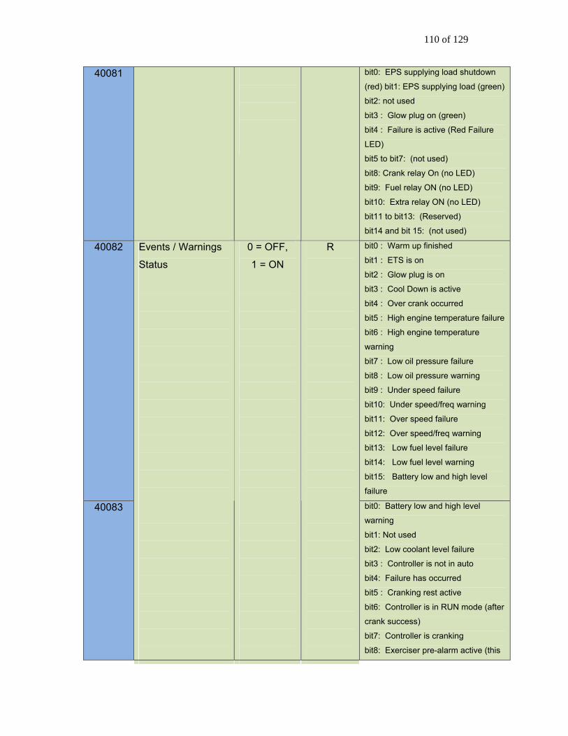
110 of 129
40081
bit0: EPS supplying load shutdown
(red) bit1: EPS supplying load (green)
bit2: not used
bit3 : Glow plug on (green)
bit4 : Failure is active (Red Failure
LED)
bit5 to bit7: (not used)
bit8: Crank relay On (no LED)
bit9: Fuel relay ON (no LED)
bit10: Extra relay ON (no LED)
bit11 to bit13: (Reserved)
bit14 and bit 15: (not used)
40082 bit0 : Warm up finished
bit1 : ETS is on
bit2 : Glow plug is on
bit3 : Cool Down is active
bit4 : Over crank occurred
bit5 : High engine temperature failure
bit6 : High engine temperature
warning
bit7 : Low oil pressure failure
bit8 : Low oil pressure warning
bit9 : Under speed failure
bit10: Under speed/freq warning
bit11: Over speed failure
bit12: Over speed/freq warning
bit13: Low fuel level failure
bit14: Low fuel level warning
bit15: Battery low and high level
failure
40083
Events / Warnings
Status
0 = OFF,
1 = ON
R
bit0: Battery low and high level
warning
bit1: Not used
bit2: Low coolant level failure
bit3 : Controller is not in auto
bit4: Failure has occurred
bit5 : Cranking rest active
bit6: Controller is in RUN mode (after
crank success)
bit7: Controller is cranking
bit8: Exerciser pre-alarm active (this

111 of 129
bit will flash)
bit9: Battery charging pre-alarm is
active (this bit will flash)
bit10: AC under voltage warning
bit11: AC over voltage warning
bit12: AC over current warning
bit13: Fuel in basin warning
bit14: Voltage Regulator Digital
Output feature is on.
bit15: Low engine temperature
warning
40084 bit0: Backlight is on
bit1: Auxiliary warning
bit2 : Maintenance is required
bit3: System is OK (definition: no
warning, including not in auto
warning)
bit4: Common fault 1 digital output
feature (warning and failure)
bit5: Common fault 2 digital output
feature (warning and failure)
bit6: Dummy load digital output
feature
bit7 : reserved
bit8 : Over current latch (AC Current
feature)
bit9: User configurable warning 1
digital output feature
bit10: User configurable warning 2
digital output feature
bit11: User configurable failure1
digital output feature
bit12: User configurable failure 2
digital output feature
bit13 to bit15: (Reserved)
40085
bit0 to bit4: (Reserved)
bit5 : Low oil level failure
bit6: Low air pressure failure digital
input
bit7: Low hydraulic failure digital
input

112 of 129
bit8: Auxiliary input failure
bit9: Low battery level failure
bit10: High battery level failure
bit11: AC over voltage failure
bit12: AC under voltage failure
bit13: AC over current failure
bit14: J1939 Loss of ECM failure
bit15: EPS load failure
40086
(f/w
versions
2.02 and
above)
bit0: PGN 61444 EEC1 not
available (engine speed)
bit1: PGN 65263 Fluid level not
available (oil pressure)
bit2: PGN 65262 Engine
temperature not available
bit3: Emergency stop active
bit4: Low battery voltage during
cranking active
bit5: Battery charger fault active
bit6: System not ready active
bit7: Low oil level warning active
40090 GSC400 hardware
version number
1.00 ~ 9.99 R
40091 GSC400 firmware
version number
1.00 ~ 9.99 R
Version format is “X.YY” ; Decimal
format where X represents a number
from 1 – 9 and is stored in the high
byte of 40090. YY represents a
decimal number from 00 to 99 and is
stored in the lower byte of 40090.
40092 ~
40095
GSC400 serial
number
4 to 7
characters
R The serial number is stored in 7 digit
decimal format with the high byte of
register 40092 containing the high
MSB and the low byte of register
40095 containing the LSB. Unused characters are stored as zeros. For
example serial number 0012450
would be stored as follows:
40092 MSB = 0
40092 LSB = 0
40093 MSB = 1
40093 LSB = 2
40094 MSB = 4
40094 LSB = 5
40095 MSB = 0

113 of 129
40095 LSB = NOT USED
2. START/STOP CONTROL AND COMMAND
Start/Stop registers are polled by the controller every 250mS.
SYSTEM DISABLE 0x5DA2
(23970)
W When 0x5DA2 is written to address
40098 this places the controller in the
OFF mode (System disabled). The
register is read in all controller
operating modes (Running, Auto,
Failure, Menu/sleep modes).
CAUTION – when received in the Running mode the controller immediately goes to the OFF mode (no cool-down is performed). When received in failure mode this will reset the system failure and revert to the OFF mode.
SYSTEM ENABLE 0x5BA4
(23460)
W When 0x5BA4 is written to address
40098 this places the controller in the
AUTO mode (waiting to start). The register is read only in the OFF mode of operation and ignored in all other operating modes.
START 0x9768
(38760)
W When 0x9768 is written to address
40098 this initiates an automatic start.
This register is only read in the AUTO mode of operation and is ignored in other modes.
40098
STOP 0x57A8
(22440)
W When 0x57A8 is written to address
40098 this initiates a shutdown/stop
of the equipment. This register is only
monitored when the system is
running (start signal received) and is
ignored in all other operating modes.
When cool down is enabled and a stop command is received the controller will proceed to the cool down mode then shutdown equipment.

114 of 129
REQUEST DM2 0xBB44 W Send a request to controller for
reading the previous DTC codes. If
the controller read the previous DTC
code success, the data will be
updated in the range of 40180 to
40244. This registers can hold
maximum 32 DTC code
3. SYSTEM CONTROL STATUS Read Only. Allows user to determine current controller mode (and sub-mode). Any active
events or warnings will be displayed up to a maximum of 6.
40100 System operating
mode
0x90
0x93
0x96
0x99
0x9C
R (Read
Only)
The possible controller modes are:
MENU/OFF SLEEP mode 0x90 (144)
OFF mode 0x93 (147)
AUTO mode 0x96 (150)
FAILURE mode 0x99 (153)
RUNNING mode 0x9C (156)
When in controller menu/OFF sleep mode if the controller is required to go to the AUTO mode a system disable command (40098) must be written followed by system enable command (40098).
40101 System Sub-state 0 ~ 40 R The controller sub-mode (if applicable):
19 DLY TO START
20 PREHEATING
21 CRANKING
22 WARM UP
23 CRANK REST
25 COOLDOWN
26 SHUTDOWN
27 IDLE RUNNING
31 IDLE COOL
32 REMOTE START RUN (RSC
contacts)
33 Front Panel Run (Manual Run)
34 MODBUS RUN (modbus start
triggered)
35 LOW BATTERY RUNNING

115 of 129
36 EXERCISER RUNNING
0 None of the above. 0 corresponds to
none of the above sub modes of
operation.
40102
~
40107
Active Event
message queue
0 ~ 255 R (Read
Only)
A maximum of 6 events/warnings are
stored concurrently. One event/warning
per register. Ensure that controller is
not in sleep mode before reading.
0 READING ABORT (DTC reading)
1 Low Voltage In Crank
2 Charger 1 Fault
3 Need Maintenance
4 CRANK FAILURE
5 Charger 2 Fault
6 Custom Warning 1
7 Custom Warning 2
8 CRANK SUCCESS
9 Empty Space
11 REQUESTING DTC
14 LAMP TEST
15 High Fuel Level
16 Warning
17 Low AC Voltage
18 Over Cur Latched
19 ↑+↓ FOR UNLATCH
20 READ DTC SUCCESS
21 FUEL OFF – If fuel turned off during
crank rest.
22 Low Engine RPM
23 High Engine RPM
24 High AC Current
25 High AC Voltage
26 High Engine Temp
27 Low Oil Pressure
28 Low Fuel Level
29 EXERCISE Prealarm
30 CHARGE Prealarm
31 NO DTC AVAILABLE
32 DM2 REQUEST FAIL
33 KEEP FUELING – If fuel remains on
during crank rest.

116 of 129
34 Lock Mark symbol (screen locked
when in Run Mode)
35 NOT IN AUTO
36 OFF FOR SILENCE
37 OFF FOR ALARM
38 POWER ON ECM...
39 WAITING ECM...
40 NEW ACTIVE DTC
41 DTC PROCESS DOWN
43 FAILURE
45 WAIT TO START
46 Low Oil Level
47 Low Speed Warn
48 Locked Rotor
49 Fuel In Basin
50 Low Battery
51 High Battery
52 AUTO FOR SILENCE
53 AUTO FOR ALARM
54 Low Engine Temperature warning
55 Open Engine Temperature sender
56 Short Engine Temperature sender
57 Open Oil Pressure sender
58 Short Oil Pressure sender
59 Open Fuel Level sender
60 Short Fuel Level sender
61 Open Oil Level sender
62 Short Oil Level sender
63 Open Fuel Basin sender
64 Short Fuel Basin sender
70 EMERGENCY STOP
71 Auxiliary Warn
72 Under Frequency warning
73 Over Frequency warning
255 (0xFF) Empty – No message in
queue
40108 Active Failure 0 ~ 44 R (Read
Only)
If the controller is in an active FAILURE
mode the failure number in register
40108 corresponds to the below failure
mode.
0 reserved

117 of 129
1 Internal reserved 1 ( ADE Read )
2 Internal reserved 2 ( KEYBOARD )
3 Internal reserved 3 ( ADC read )
4 Internal reserved 4 ( RS485 )
5 Internal reserved 5 ( RS232 )
6 Internal reserved 6 ( ADE Write )
7 Internal reserved 7 ( TLE6230 )
8 Internal reserved 8 ( EEPROM )
9 (Reserved )
10 HIGH ENGINE TEMP
11 LOW OIL PRESSURE
12 UNDER SPEED
13 OVER SPEED
14 LOW FUEL LEVEL
15 LOW BATTERY
16 LOW COOLANT
17 OVER CRANK
18 OVER VOLTAGE
19 UNDER VOLTAGE
20 OVER CURRENT
21 EPS LOADS ERROR
22 LOW AIR PRESSURE
23 LOW HYDRAULIC
24 LOW OIL LEVEL
25 LOCKED ROTOR
26 HIGH BATTERY
27 LOSS OF ECM COMMUNICATION
28 OPEN ENG TEMP (applies to both
High and Low Engine Temperature)
29 SHORT ENG TEMP (applies to both
High and Low Engine Temperature)
30 OPEN OIL PRES
31 SHORT OIL PRES
32 OPEN FUEL LEVEL
33 SHORT FUEL LEVEL
34 OPEN OIL LEVEL
35 SHORT OIL LEVEL
36 OPEN FUEL BASIN
37 SHORT FUEL BASIN
40 AUXILIARY FAIL
41 UNDER FREQUENCY
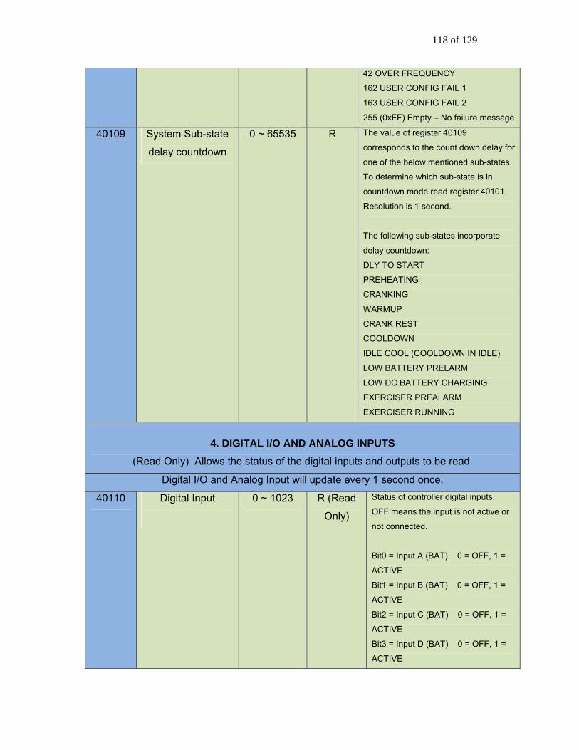
118 of 129
42 OVER FREQUENCY
162 USER CONFIG FAIL 1
163 USER CONFIG FAIL 2
255 (0xFF) Empty – No failure message
40109 System Sub-state
delay countdown
0 ~ 65535 R The value of register 40109
corresponds to the count down delay for
one of the below mentioned sub-states.
To determine which sub-state is in
countdown mode read register 40101.
Resolution is 1 second.
The following sub-states incorporate
delay countdown:
DLY TO START
PREHEATING
CRANKING
WARMUP
CRANK REST
COOLDOWN
IDLE COOL (COOLDOWN IN IDLE)
LOW BATTERY PRELARM
LOW DC BATTERY CHARGING
EXERCISER PREALARM
EXERCISER RUNNING
4. DIGITAL I/O AND ANALOG INPUTS (Read Only) Allows the status of the digital inputs and outputs to be read.
Digital I/O and Analog Input will update every 1 second once.
40110 Digital Input
0 ~ 1023 R (Read
Only)
Status of controller digital inputs.
OFF means the input is not active or
not connected.
Bit0 = Input A (BAT) 0 = OFF, 1 =
ACTIVE
Bit1 = Input B (BAT) 0 = OFF, 1 =
ACTIVE
Bit2 = Input C (BAT) 0 = OFF, 1 =
ACTIVE
Bit3 = Input D (BAT) 0 = OFF, 1 =
ACTIVE

119 of 129
Bit4 = Input E (GND) 1 = OFF, 0 =
ACTIVE
Bit5 = Input F (GND) 1 = OFF, 0 =
ACTIVE
Bit6 = Input G (GND) 1 = OFF, 0 =
ACTIVE
Bit7 = Input H (GND) 1 = OFF, 0 =
ACTIVE
Bit8 = Start/Stop 1 = OFF, 0 =
ACTIVE
Bit9 =Emergency Stop 0 = OFF, 1 =
ACTIVE
Note: Do not read the start/stop digital input (Bit 8) as a means to determine if start signal active or not active, please read the register 40100 for system state.
40111 Digital Output
0~2047
R (Read
Only)
Status of controller outputs. 0
corresponds to output OFF or NOT
ACTIVE, while a 1 corresponds to
output ON or ACTIVE.
Bit0 = Output A 0 = OFF, 1 = ACTIVE
Bit1 = Output B 0 = OFF, 1 = ACTIVE
Bit2 = Output C 0 = OFF, 1 = ACTIVE
Bit3 = Output D 0 = OFF, 1 = ACTIVE
Bit4 = Output E 0 = OFF, 1 = ACTIVE
Bit5 = Output F 0 = OFF, 1 = ACTIVE
Bit6 = Output G 0 = OFF, 1 = ACTIVE
Bit7 = Output H 0 = OFF, 1 = ACTIVE
Bit8 = Extra Relay 0 = OFF, 1 = ACTIVE
Bit9 = Fuel Relay 0 = OFF, 1 = ACTIVE
Bit10 = Crank Rly 0 = OFF, 1 = ACTIVE

120 of 129
Advanced Modbus register support
1. ENGINE-GENERATOR PARAMETERS (Read Only)
Running parameters will update every 1 second. The engine speed, high engine
temperature, low engine temperature, oil pressure, and fuel level parameters display
0xFF01 if not available (if source is J1939). The six sender inputs (High Engine
Temperature, Low Engine Temperature, Fuel Level, Oil Pressure, Oil Level, and Fuel In
Basin) parameters display 0xFF00 if set to switch or disabled.
40150 Engine Speed 0 ~ 6553.0 R 1 bit equal 0.1 RPM
Reading 18000
corresponds to
1800RPM
RPM
40151 High Engine
Temperature
0 ~ 250.0 R 1 bit equal 0.1 unit
Reading 1000
corresponds to 100.0C
C
40153 Low Engine
Temperature
0 ~ 250.0 R 1 bit equal 0.1 unit
Reading 1000
corresponds to 100.0C
C
40154 Fuel Level 0.0 ~ 100.0 R 1 bit equal to 0.1%
Reading 1000
corresponds to 100.0%
%
40155 Oil Pressure 0.0 ~
1000.0
R 1 bit equal 0.1 unit
Reading 1000
corresponds to
100.0KPa
KPa
40156 Oil Level 0.0 ~ 100.0 R 1 bit equal to 0.1%
Reading 1000
corresponds to 100.0%
%
40157 Fuel In Basin 0 ~ 100.0 R 1 bit equal to 0.1%
Reading 1000
corresponds to 100.0%
%
40160 Line Voltage A-B R V
40161 Line Voltage B-C
0~999.9
R
1 bit 0.1V
Reading 9999 V

121 of 129
40162 Line Voltage C-A R V
40163 Phase Voltage A R V
40164 Phase Voltage B R V
40165 Phase Voltage C R
corresponds to 999.9.V
V
40167 Phase A Current R A
40168 Phase B Current R A
40169 Phase C Current
0~999.9
R
1 bit equal to 0.1A
Reading 9999
corresponds to 999.9A A
40170 AC Frequency 0 ~ 100.0 R AC frequency
Reading 600
corresponds to 60.0Hz
Hz
40172 ~
40173
Engine Hours (new
-f/w versions 2.02
and above)
0~255999.9 R 32bit word: register 172
is low 16bits, 173 is
high 16bits. 1bit = 0.1
Hours
Hours
40174 Battery Voltage 0 ~ 31.8 R 1 bit equal 0.1V
Reading 318
corresponds to 31.8V
V
40175 PCB Board
Temperature
-55 ~ 130
Signed
Integer 16
bit
R 1 bit 0.1C
Reading 1000
corresponds to 100.0C
Positive or negative
values can be identified
by reading the high byte
of MSB. A 1 in bit 15
corresponds to a
negative number while
a 0 corresponds to a
positive number
C
40176 Current Run time
(Total run time on active
running event).
NOTE: Timer is reset to
Zero after active
running event has been
terminated (OFF or
AUTO mode waiting to
start)
0 ~ 6553.5 R 1 bit 0.1 hour
65535 corresponds to
6553.5Hs
Hours
40177 ~
40178
Engine Hours (old
way – use registers
0~255999.9 R Total Accumulated
running hours, the Hours

122 of 129
40172/40173
instead)
reading in 40177, 1 bit
equal to 0.1 hour. The
reading in 40178, 1 bit
equal to 1000 hours. So
the total hours = 40178
* 1000 + 40177/10
40145 Maintenance Time -1000 ~
+1000 Signed Integer
16 bit
R The unit is 0.1 hour (1 bit = 0.1 hour);
Positive values count down the hours
to next maintenance. Negative values
count up the hours since
maintenance should have been
performed. Positive or negative
values can be identified by read the
high byte of MSB. A 1 in bit 15
corresponds to a negative number
while a 0 corresponds to a positive
number.
2. EVENTS HISTORY LOG
Read Previous
Entry
0x6C93
(27795) W 40130
Read Next Entry 0x639C
(25500) W
Write control command to holding
register address.
The controller will check the log request every 1 second. Each time a new command is
received, the controller will scroll either down or up one message (until it reaches either the
bottom or top of the message log), one message and update the log content in address
40131 to 40141. Once at the top of the log, registers 40131 to 40141 are not changed if a
“Read Previous Entry” command is received. Once at the bottom of the log, registers 40131
to 40141 are not changed if a “Read Next Entry” command is received. After 20s of
receiving further commands in register 40130, all registers are cleared (i.e. set to 0).
40131 Log Type Only
supports the
values listed
in format
column.
R 1 Internal reserved 1 ( ADE Read )
2 Internal reserved 2 ( KEYBOARD)
3 Internal reserved 3 ( ADC read )
4 Internal reserved 4 ( RS485 )
5 Internal reserved 5 ( RS232 )
6 Internal reserved 6 ( ADE Write )
7 Internal reserved 7 ( TLE6230 )
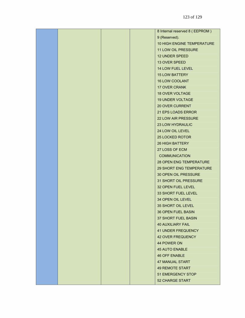
123 of 129
8 Internal reserved 8 ( EEPROM )
9 (Reserved).
10 HIGH ENGINE TEMPERATURE
11 LOW OIL PRESSURE
12 UNDER SPEED
13 OVER SPEED
14 LOW FUEL LEVEL
15 LOW BATTERY
16 LOW COOLANT
17 OVER CRANK
18 OVER VOLTAGE
19 UNDER VOLTAGE
20 OVER CURRENT
21 EPS LOADS ERROR
22 LOW AIR PRESSURE
23 LOW HYDRAULIC
24 LOW OIL LEVEL
25 LOCKED ROTOR
26 HIGH BATTERY
27 LOSS OF ECM
COMMUNICATION
28 OPEN ENG TEMPERATURE
29 SHORT ENG TEMPERATURE
30 OPEN OIL PRESSURE
31 SHORT OIL PRESSURE
32 OPEN FUEL LEVEL
33 SHORT FUEL LEVEL
34 OPEN OIL LEVEL
35 SHORT OIL LEVEL
36 OPEN FUEL BASIN
37 SHORT FUEL BASIN
40 AUXILIARY FAIL
41 UNDER FREQUENCY
42 OVER FREQUENCY
44 POWER ON
45 AUTO ENABLE
46 OFF ENABLE
47 MANUAL START
49 REMOTE START
51 EMERGENCY STOP
52 CHARGE START

124 of 129
53 CHARGE OVER
54 MAINTAIN NEEDED
55 INITIALIZING
56 MAINTAINED
57 NEXT EXERCISER
58 RUN EXERCISER
59 EXERCISER OVER
62 LOG CORRUPTED
63 MODBUS START
162 (0xA2) CONFIG FAIL 1
163 (0xA3) CONFIG FAIL 2
233 (0xE9) DTC
40132 Log Time stamp
Minutes
Decimal
0 ~ 59
Decimal format
High 4-bit tens 0 ~ 5
Low 4-bit ones 0 ~ 9
Minute
40133 Log Time stamp
Hours
Decimal
0 ~ 23
Decimal format
High 4-bit tens 0 ~ 2
Low 4-bit ones 0 ~ 9
Hour
40134 Log Time stamp
Date
Decimal
1 ~ 31
Decimal format
High 4-bit tens 0 ~ 3
Low 4-bit ones 0 ~ 9
Day
40135 Log Time stamp
Month
Decimal
1 ~ 12
R
Decimal format
High 4-bit tens 0 ~ 1
Low 4-bit ones 0 ~ 9
Month
40136 0 ~ 255 Lowest byte of SPN (bit 8 MSB)
40137 0 ~ 39 Middle byte of SPN (bit 8 MSB)
40138 0 ~ 31 3 highest bits of SPN and the FMI (bit
8 is SPN MSB and bit 5 is FMI MSB)
40139
Log DTC code.
Only valid if entry
contains DTC
message (if Log
Type register –
40131 equals 233).
R
Bit 8 CM, other 7 bits OC (bit 7 MSB)
40140 Log Sequence 1 ~ 100 R Current log being read.
40141 Total Log Number 1 ~ 100 R Total number of entries in the log.
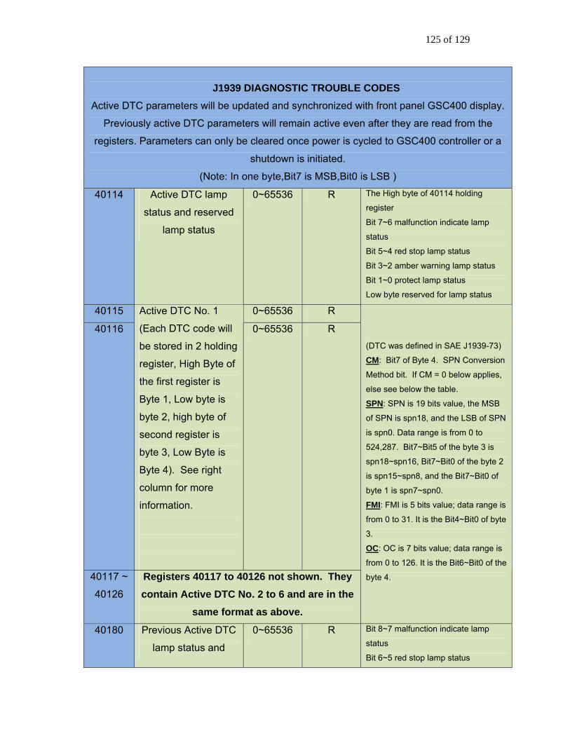
125 of 129
J1939 DIAGNOSTIC TROUBLE CODES Active DTC parameters will be updated and synchronized with front panel GSC400 display.
Previously active DTC parameters will remain active even after they are read from the
registers. Parameters can only be cleared once power is cycled to GSC400 controller or a
shutdown is initiated.
(Note: In one byte,Bit7 is MSB,Bit0 is LSB )
40114 Active DTC lamp
status and reserved
lamp status
0~65536 R The High byte of 40114 holding
register
Bit 7~6 malfunction indicate lamp
status
Bit 5~4 red stop lamp status
Bit 3~2 amber warning lamp status
Bit 1~0 protect lamp status
Low byte reserved for lamp status
40115 0~65536 R
40116
Active DTC No. 1
(Each DTC code will
be stored in 2 holding
register, High Byte of
the first register is
Byte 1, Low byte is
byte 2, high byte of
second register is
byte 3, Low Byte is
Byte 4). See right
column for more
information.
0~65536 R
40117 ~
40126
Registers 40117 to 40126 not shown. They contain Active DTC No. 2 to 6 and are in the
same format as above.
(DTC was defined in SAE J1939-73)
CM: Bit7 of Byte 4. SPN Conversion
Method bit. If CM = 0 below applies,
else see below the table. SPN: SPN is 19 bits value, the MSB
of SPN is spn18, and the LSB of SPN
is spn0. Data range is from 0 to
524,287. Bit7~Bit5 of the byte 3 is
spn18~spn16, Bit7~Bit0 of the byte 2
is spn15~spn8, and the Bit7~Bit0 of
byte 1 is spn7~spn0.
FMI: FMI is 5 bits value; data range is
from 0 to 31. It is the Bit4~Bit0 of byte
3.
OC: OC is 7 bits value; data range is
from 0 to 126. It is the Bit6~Bit0 of the
byte 4.
40180 Previous Active DTC
lamp status and
0~65536 R Bit 8~7 malfunction indicate lamp
status
Bit 6~5 red stop lamp status

126 of 129
reserved lamp status Bit 4~3 amber warning lamp status
Bit 2~1 protect lamp status
Low byte reserved for lamp status 40181 0~65536 R
40182
Previous Active DTC
No. 1 (Same format
as Active DTC
registers above)
0~65536 R
40183 ~
40244
Registers 40183 to 40244 are not shown. They contain Previously Active DTC No. 2 to
32 and are in the same format as above.
Same format as Active DTC
registers above.
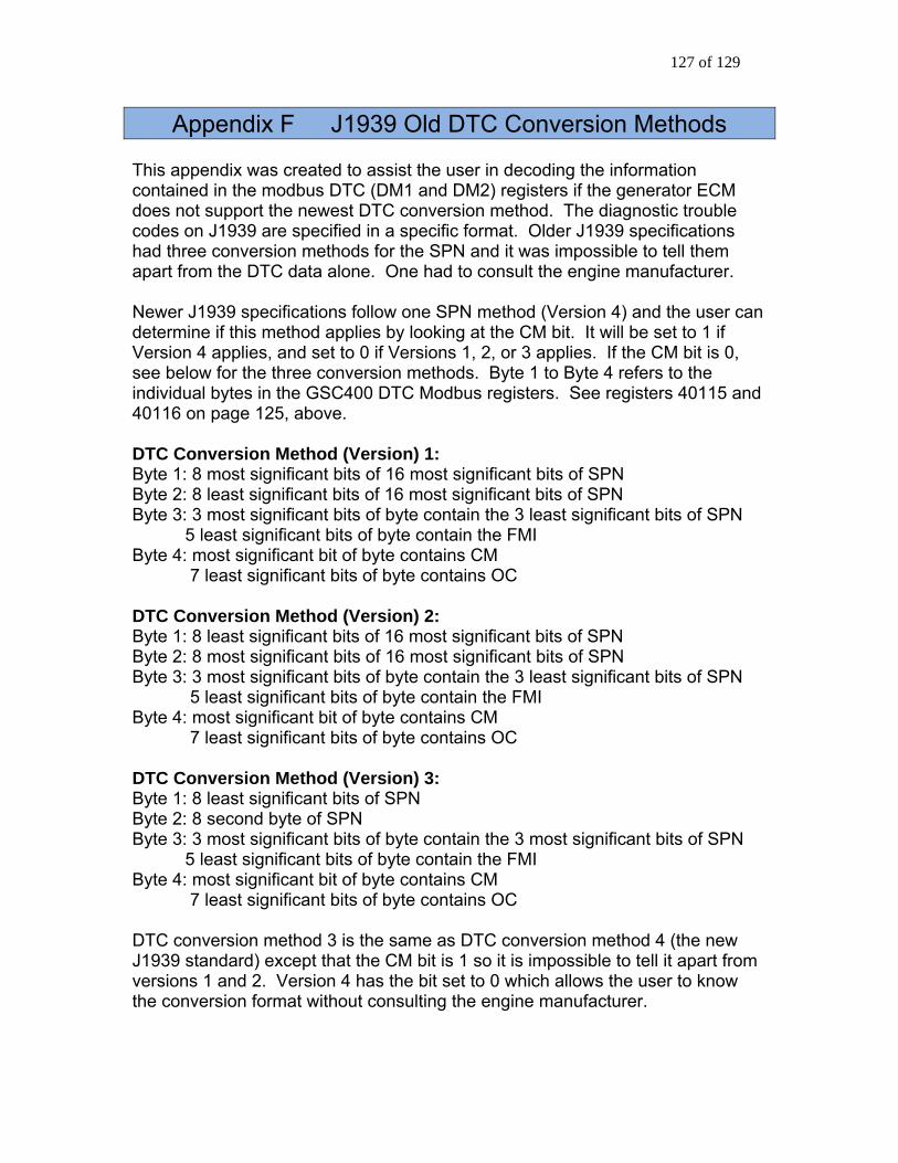
127 of 129
Appendix F J1939 Old DTC Conversion Methods This appendix was created to assist the user in decoding the information contained in the modbus DTC (DM1 and DM2) registers if the generator ECM does not support the newest DTC conversion method. The diagnostic trouble codes on J1939 are specified in a specific format. Older J1939 specifications had three conversion methods for the SPN and it was impossible to tell them apart from the DTC data alone. One had to consult the engine manufacturer. Newer J1939 specifications follow one SPN method (Version 4) and the user can determine if this method applies by looking at the CM bit. It will be set to 1 if Version 4 applies, and set to 0 if Versions 1, 2, or 3 applies. If the CM bit is 0, see below for the three conversion methods. Byte 1 to Byte 4 refers to the individual bytes in the GSC400 DTC Modbus registers. See registers 40115 and 40116 on page 125, above. DTC Conversion Method (Version) 1: Byte 1: 8 most significant bits of 16 most significant bits of SPN Byte 2: 8 least significant bits of 16 most significant bits of SPN Byte 3: 3 most significant bits of byte contain the 3 least significant bits of SPN 5 least significant bits of byte contain the FMI Byte 4: most significant bit of byte contains CM 7 least significant bits of byte contains OC DTC Conversion Method (Version) 2: Byte 1: 8 least significant bits of 16 most significant bits of SPN Byte 2: 8 most significant bits of 16 most significant bits of SPN Byte 3: 3 most significant bits of byte contain the 3 least significant bits of SPN 5 least significant bits of byte contain the FMI Byte 4: most significant bit of byte contains CM 7 least significant bits of byte contains OC DTC Conversion Method (Version) 3: Byte 1: 8 least significant bits of SPN Byte 2: 8 second byte of SPN Byte 3: 3 most significant bits of byte contain the 3 most significant bits of SPN 5 least significant bits of byte contain the FMI Byte 4: most significant bit of byte contains CM 7 least significant bits of byte contains OC DTC conversion method 3 is the same as DTC conversion method 4 (the new J1939 standard) except that the CM bit is 1 so it is impossible to tell it apart from versions 1 and 2. Version 4 has the bit set to 0 which allows the user to know the conversion format without consulting the engine manufacturer.

128 of 129
Appendix G Additional Drawings The follow pages include various drawings that may be of benefit.

129 of 129