MAKER:ConvertingtheSketchofanArtefactintoaCompositeBezierCurve · PDF...
16
Paper ID #11497 MAKER: Converting the Sketch of an Artefact into a Composite Bezier Curve and Producing it in the Boxford Milling Machine Dr. Sangarappillai Sivaloganathan, United Arab Emirates University Dr Sangarappillai Sivaloganathan – Siva is a Srilankan by birth and a citizen of the United Kingdom. His experience in Sri-lanka started with an year’s post-graduate apprenticeship in the manufacturing shops of the Government Railway and nine years in the Cement Industry. He graduated as a Mechanical Engineer from University of Srilanka, and obtained his Masters from the University of Aston and PhD from City University of London, both in the UK. He started his career in the UK as the Senior Research Assistant at the SERC Engineering Design Centre. He joined Brunel University in 1995 where he worked for 18 years before joining United Arab Emirates University in August 2011. During his stay at Brunel he has worked with many British industries. Dr Sivaloganathan is a keen researcher in Design and was the Convenor for the Engineering Design Conferences in 1998 and 2000. He has published more than 75 papers in reputed journals and conferences. Mr. Hayder Zulafqar Ali, University Instructor Hayder Ali is working as an ’instructor’ in mechanical engineering department, United Arab Emirates University (UAEU). Before joining UAEU, he has been trained on a long term technology transfer (plastic mold making) project between government of Pakistan and government of Japan. He holds a master degree in Mechatronic Engineering and bachelor in Mechanical Engineering both from the University of Engineering and Technology Lahore Pakistan. He has extensive teaching and industrial experience. Mrs. IMAN ABDULWAHEED, United Arab Emirates University Mrs IMAN ABDULWAHEED;graduated from United Emirates Emirates University in February in 2014 with a mechanical engineering degree.During her residency in the university she was an enthusiastic par- ticipant in academic and extracurricular activities.She was an active member and office holder in ASME, ASAA and Robotics and Aerospace clubs.She was an undergraduate researcher and has worked with sev- eral faculty members.She has coauthored a paper which was presented in International Renewable Energy Conference in 2014.She won the second place in Think Science Competition in 2014 and the fifth place in Tamaiaz Falak Tayyeb Competition in 2015. Ms. Sayeda Abboud Al Ameri, United Arab Emirates University Ms. SAYEDA ABBOUD AL AMERI ; graduated from United Arab Emirates University in February 2014 with a mechanical engineering degree. During her residency in the university she was an enthusiastic participant in academic and extracurricular activities. She was an active member and office holder in ASME and Robotics and Aerospace clubs. She was an undergraduate researcher and has worked with several faculty members. She has coauthored a paper which was presented in the International Renewable Energy Conference in 2014. She won the second place in Think Science Competition in 2014 and the fifth place in Tamaiaz Falak Tayyeb Competition in 2015. Sayeda is undergoing advanced training at AMMROC (Advanced Military Maintenance Overhaul Center) in UAE. c American Society for Engineering Education, 2015 Page 26.1115.1
Transcript of MAKER:ConvertingtheSketchofanArtefactintoaCompositeBezierCurve · PDF...

Paper ID #11497
MAKER: Converting the Sketch of an Artefact into a Composite Bezier Curveand Producing it in the Boxford Milling Machine
Dr. Sangarappillai Sivaloganathan, United Arab Emirates University
Dr Sangarappillai Sivaloganathan – Siva is a Srilankan by birth and a citizen of the United Kingdom. Hisexperience in Sri-lanka started with an year’s post-graduate apprenticeship in the manufacturing shops ofthe Government Railway and nine years in the Cement Industry. He graduated as a Mechanical Engineerfrom University of Srilanka, and obtained his Masters from the University of Aston and PhD from CityUniversity of London, both in the UK. He started his career in the UK as the Senior Research Assistant atthe SERC Engineering Design Centre. He joined Brunel University in 1995 where he worked for 18 yearsbefore joining United Arab Emirates University in August 2011. During his stay at Brunel he has workedwith many British industries. Dr Sivaloganathan is a keen researcher in Design and was the Convenor forthe Engineering Design Conferences in 1998 and 2000. He has published more than 75 papers in reputedjournals and conferences.
Mr. Hayder Zulafqar Ali, University Instructor
Hayder Ali is working as an ’instructor’ in mechanical engineering department, United Arab EmiratesUniversity (UAEU). Before joining UAEU, he has been trained on a long term technology transfer (plasticmold making) project between government of Pakistan and government of Japan.
He holds a master degree in Mechatronic Engineering and bachelor in Mechanical Engineering both fromthe University of Engineering and Technology Lahore Pakistan. He has extensive teaching and industrialexperience.
Mrs. IMAN ABDULWAHEED, United Arab Emirates University
Mrs IMAN ABDULWAHEED;graduated from United Emirates Emirates University in February in 2014with a mechanical engineering degree.During her residency in the university she was an enthusiastic par-ticipant in academic and extracurricular activities.She was an active member and office holder in ASME,ASAA and Robotics and Aerospace clubs.She was an undergraduate researcher and has worked with sev-eral faculty members.She has coauthored a paper which was presented in International Renewable EnergyConference in 2014.She won the second place in Think Science Competition in 2014 and the fifth placein Tamaiaz Falak Tayyeb Competition in 2015.
Ms. Sayeda Abboud Al Ameri, United Arab Emirates University
Ms. SAYEDA ABBOUD AL AMERI ; graduated from United Arab Emirates University in February2014 with a mechanical engineering degree. During her residency in the university she was an enthusiasticparticipant in academic and extracurricular activities. She was an active member and office holder inASME and Robotics and Aerospace clubs. She was an undergraduate researcher and has worked withseveral faculty members. She has coauthored a paper which was presented in the International RenewableEnergy Conference in 2014. She won the second place in Think Science Competition in 2014 and thefifth place in Tamaiaz Falak Tayyeb Competition in 2015. Sayeda is undergoing advanced training atAMMROC (Advanced Military Maintenance Overhaul Center) in UAE.
c©American Society for Engineering Education, 2015
Page 26.1115.1
Converting the Sketch of an Artefact into a Composite Bezier Curve and
Producing it in the Boxford Milling Machine
Abstract:
Students in an Introduction to CAM course would have theory classes augmented by hands-
on experiments in the lab. At United Arab Emirates University (UAEU) the students were
taught parametric curves and NC programming in the theory classes. A project to inspire the
students and excite their creativity while cementing the theory they have learned was needed.
A
milling project, a memorabilia clock, was chosen as the candidate. The cross section
was drawn on a graph paper and was broken into an assemblage of straight line and curve
segments. The nodal points, tangency condition and optional intermediate points described
the assemblage. It was transferred to CorelDraw software and the shape was modelled and
the control points were obtained. The model of the cross section was transferred to the
Boxford Milling Machine as an assemblage of straight lines and Bezier curve segments
defined by their control points. The product was manufactured. The students had an exciting
experience and learned an important practical side of Bezier Curves. The methodology
developed is generic and can be used to make similar products.
1 Introduction
The course, Introduction to Computer Aided Manufacturing has several learning outcomes
including (i) students will be able to apply the knowledge of mathematics and engineering
science to model engineering shapes using parametric curves and (ii) students will be able to
draw and transfer data using computerised drawing tools and programming tools. The
laboratory has (i) four CNC bench lathes (ii) four CNC bench milling machines (BOXFORD
- 190VMCxi Vertical Machining Centre) (iii) a Cincinnatti Arrow 2 series vertical machining
center and (iv) a DMG horizontal machining center. The students have theory classes
augmented by hands-on experiments in the lab. In the theory classes the students were taught
parametric curves and NC programming. A project to inspire the students and excite their
creativity while cementing what they have learned was needed. Boxford milling machines
were fitted with the CAM package, BOXFORD CAD/CAM Design Tools V10, which can
accept third order Bezier curves defined by their four control points. However the size of the
work pieces they could handle was limited. This led to the choice of memorabilia items as the
area for the project. A memorabilia table clock was chosen as the candidate. Section 2
describes the project as given to the students, the theory involved and the method employed
in the design, and manufacturing. There were eighteen student groups of three who
participated in the exercise. A typical sample of the work is described in section 3.
Manufacturing the product became a challenge because of the shortcomings of the machines.
Section 4 describes Assessing and evaluating the work. Section 5 describes the learning
experience and Section 6 draws conclusions.
2 The Project
The project was to design a memorabilia clock for UAEU consisting of three parts (i) a clock
insert bought outside (ii) a body to house the clock insert and the name tower or logo and (iii)
the name tower itself. The main design task is that of the body. In order for the students to
feel the importance and grasp the holistic picture they were asked to work as partners of a
fictitious company making a bid. The brief given to students is as follows:
Page 26.1115.2

Following the traditions of big universities, UAEU wants to produce some memorabilia. A
table clock has been considered with several other ideas and has been selected as the most
appropriate one. It consists of a suitably designed stand onto which a clock insert is fixed.
The manufacturing process considered for the stand is a 2.5D profile milling followed by the
drilling of a hole and gluing a tower of the University Logo. The university wants to make
1000 pieces of this. It wants to contract this job out. You are a group of mechanical
engineering graduates just graduated from UAEU and are in the process of forming a
product design and manufacturing company. You want to have this contract to launch your
company. But the competition is very high. Eighteen companies including yours have
recorded interest in bidding for the contract. Make a bid on the specified format given and
make a presentation to the interviewing board to convince them to choose your bid.
The students were told that the product should have the emotional appeal reflecting the
characteristic character of the region and product differentiation, a rating of product’s
uniqueness and consistency with the product’s corporate identity.
2.1 Theory
Bezier curves are named after their inventor, Dr. Pierre Bezier. He was an engineer with the
Renault car company and set out in the early 1960’s to develop a curve formulation, which
would lend itself to shape design [1]. The motivations and the passage of the invention is
given in a letter written by Dr Bezier to Christophe Rabut which has been published by Rabut
[2]. Text books [3 4] describe the theory in detail. A summary of the relevant parts is given
here.
A third order Bezier curve is the point-bounded collection of points, which are the weighted
sum of four special points called the Control Points. If the control points are marked by the
capital letters like ( ) and a point on the curve is marked by the small letters like
( ) then a general point on a third order curve can be written as
where p is an arbitrary point on the curve
are control points
are the blending functions
The blending functions are the Bernstein functions defined as the terms in the following
expansion for a third order curve.
(( ) ) ( ) ( ) ( ) Where u is the independent parameter, which takes the value 0 at the starting point and 1 at
the finishing point of a Bezier curve segment.
Expanding these terms and putting them in matrix form gives
[ ] [ ] [
]
Substituting this in the defining equation gives
Page 26.1115.3

[ ] [ ] [
] [
]
If the curve passes through four points this can be written as
[
]
[
]
[
] [
]
Thus if four points on the curve are known, the control points can be calculated. Alternately
if the four control points are known points on the curve can be calculated.
2.1.1 Tangency Condition
Two curves, described by two sets of parametric equations, merge smoothly when they have
the same slope at the meeting point. This is called the tangency condition. Consider the
curves and as shown in Figure 2.
Figure 2: Two Bezier Curves Merging Smoothly
Then the tangency condition for smooth merging is the slope of curve at the point
should be equal to the slope of at .
Let the equation of a Bezier curve be
( ) ( ) ( ) ( )
Then ( )
( ) [( )
( )( )]
[ ]
When this becomes ( ) and
When this becomes ( )
Page 26.1115.4
This means that the tangent vector at is along the line connecting for the curve
and along the line connecting for the curve of . This follows
that the points must lie on a straight line for smooth joining. Thus the tangency
condition for smooth joint becomes, points must be collinear.
2.2 The Methodology
The methodology starts with the visualization of the product and making a ‘Bounding box’.
This will particularly be useful to proportion all the concepts to the same level. In the second
step creativity and artistic thinking have been used to bring character, and sketch the cross
section of the object to be milled. Make as many sketches as possible on graph (gridded)
paper and then choose one. Once the cross section is chosen the next step is to break the
sketch into a number of curve segments and label them. Read the coordinates of the nodal
points from the graph paper and read any intermediate points in each segment through which
the curve has to pass. Also note down the tangency condition where the curve segments meet.
Now the curve is ready for transfer to CorelDraw software [5]. In CorelDraw open a file with
a graph paper template as the fourth step. In the fifth step draw a polygon through the nodal
points recorded earlier when segmenting the sketch. In the next step using the Bezier Tool
from the software, convert the straight-line segments that have to be curves, into Bezier curve
segments. Looking at the tangent vectors at each node ensure the required tangency condition
is met. Make sure that the curve passes through the required intermediate points.
to
Figure 3: Steps in the Transfer of the Sketch to CorelDraw
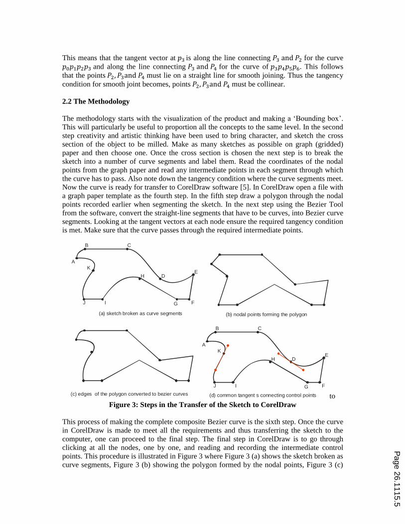
This process of making the complete composite Bezier curve is the sixth step. Once the curve
in CorelDraw is made to meet all the requirements and thus transferring the sketch to the
computer, one can proceed to the final step. The final step in CorelDraw is to go through
clicking at all the nodes, one by one, and reading and recording the intermediate control
points. This procedure is illustrated in Figure 3 where Figure 3 (a) shows the sketch broken as
curve segments, Figure 3 (b) showing the polygon formed by the nodal points, Figure 3 (c)
A
B C
DE
FG
H
IJ
K
A
B C
DE
FG
H
IJ
K
(a) sketch broken as curve segments (b) nodal points forming the polygon
(c) edges of the polygon converted to bezier curves (d) common tangent s connecting control points
Page 26.1115.5

showing the partially converted sketch and Figure 3 (d) completed sketch with some of the
common tangents.
A similar procedure is repeated in the BOXFORD CAD/CAM Design Tools V10 software in
the Boxford Milling Machine. A polygon is drawn and the curve segments are constructed by
keying in the intermediate control points. Once the curve definition is completed the software
is prompted to generate the NC code. The generated code can be simulated to prove the code
and edit if necessary. The last step is to secure the work piece, set the datum planes and
manufacture the body. The clock is then inserted and the logo is mounted. The methodology
is schematically illustrated in the flowchart shown in Figure 4.
Figure 4: The Methodology
3 Typical Sample of the Student Work
Members from one of the eighteen groups are part of the authoring group and they mainly
wrote this section. This work has been done during the 2011/2012 academic year.
Concept generation and selection was an important step that had to be followed for producing
the product. Each member of the teams drew different concept sketches. All eighteen groups
had novel designs that reflected their aspirations and feelings for this project. The concept
selection was one of the most important decisions that had to be taken in the project. All
eighteen groups had chosen concepts that represented the conscience of the region. Some of
the interesting concepts chosen by the students are as follows:
i. The first concept was the striking features of the ‘Lion’, which also reflected the
graduate power.
ii. Another concept was the ‘Camel’, which can survive for several days without water
and which provided means of transport across the desert permitting the UAE’s Bedu
nomads to move from place to place in search of food and water. Without the camel,
the hard, nomadic life of the UAE’s Bedu would not have been possible.
Ensure Tangency Conditionsare met and any intermediatepoints are on the Curve andRead the Control points
Create the profile in the Milling Machine and generate the NCcode and connect to the Machine
Mount the Workpiece and Set the Datum Planes.Simulate the run.
Produce the Part and make thehole for the clock insert.Now fix the Clock and Logo
Draw a Polygon with theNode Points as the verticesand convert the requiredsegments into Bezier Curves
Draw concept sketcheson graph Paper andchoose one
Break chosen conceptinto simple curve segmentsand read the Node Points
Open CorelDraw with aGraph Paper Template
Page 26.1115.6
iii. Religion is a very important component of UAE society and another very important
concept was the ‘Worshipping Man’. Worship is an all-inclusive term for all the god
lovers and it is everything one says or does for the pleasure of Allah.
All concepts looked innovative and would have looked even better when coloured with
paints. Concepts have been chosen based on four important requirements which are (i)
attractive appearance with an underlying meaning (ii) ease of manufacturing, (iii) stability of
the product and (iv) uniqueness of the product.
Some of the concepts had several special geometric details specially the curves and their
targeted smoothness. One of the challenges in this project was choosing a CAD software with
sufficiently high technology to convert this sketch into digital representation. The theoretical
lessons on parametric curves helped to visualize different types of Bezier curves. Some of
these considerations are (i) curves and points which were contained within the control
polygon (ii) curves crossing the control polygon and (iii) different tangent shapes at the nodes
and their mathematical conditions.
The conceptual sketches were partitioned with due consideration for different characteristic
features of the profile. There were many intricate shapes that had to be taken care of. Use of
CorelDraw permitted the consideration of more points in the partitions than those allowed by
mathematics. Some segments were small and some segments were big. Some segments were
straight lines. The ‘to and fro’ movement between the sketch and CorelDraw achieved a full
understanding of Bezier curves. A simple profile having all different types of Bezier Curves
is chosen here for description.
3.1 Partitioning the Sketch
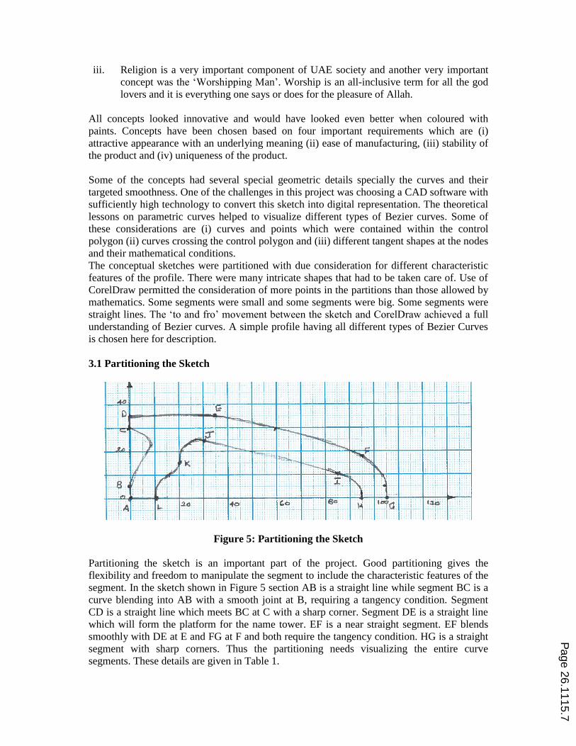
Figure 5: Partitioning the Sketch
Partitioning the sketch is an important part of the project. Good partitioning gives the
flexibility and freedom to manipulate the segment to include the characteristic features of the
segment. In the sketch shown in Figure 5 section AB is a straight line while segment BC is a
curve blending into AB with a smooth joint at B, requiring a tangency condition. Segment
CD is a straight line which meets BC at C with a sharp corner. Segment DE is a straight line
which will form the platform for the name tower. EF is a near straight segment. EF blends
smoothly with DE at E and FG at F and both require the tangency condition. HG is a straight
segment with sharp corners. Thus the partitioning needs visualizing the entire curve
segments. These details are given in Table 1.
Page 26.1115.7

Table 1: Curve Segment and Properties
Curve Segment Properties
AB Vertical straight line
BC Bezier curve with smooth joint at B
CD Vertical Straight line with 900 joint at C
DE Horizontal Straight line with 900 joint at D
EF Near Straight with tangency condition at E & F
FG Smooth joint at G and 900 joint at H
GH Horizontal line with 900 joints at G & H
HI Simple curve
IJ Straight line with smooth joints at both I & J
JK Bezier curve with smooth joints at both J & K
KL Bezier Curve with vertical tangent vectors
LA Horizontal line with 900 joints at L & A
The coordinates of the nodal points A, B, C, D, E, F, G, H, I, J, K and L are taken from the
graph paper. Optional interim points were also recorded for the curves. They will be useful if
mathematical methods are to be used instead of CorelDraw.
Table 2: Nodal Points
Nodal Point Coordinates Optional Interim
points
A (0, 0)
B (0, 5) (15, 10) in BC
C (0, 25)
D (0, 30)
E (35, 30) (60, 30) in EF
F (90, 17.5) (105, 5) in FG
G (105, 0)
H (95, 0) (95, 3) in HI
I (85, 10)
J (30, 25) (24, 23) in JK
K (20, 15) (15, 10) in KL
L (10, 0)
3.2 Marking the Nodes in CorelDraw and Drawing the Polygon
Open CorelDraw with graph paper template and mark off the nodal points. Connect them as a
continuous line polygon of straight line segments as shown in Figure 6.
Page 26.1115.8

Figure 6: Nodal Points and the Polygon in CorelDraw Software
3.3 Convert the Required Straight Line Segments into Bezier Curves
The first Straight line segment that needs to be converted to a Bezier curve is BC. The main
thing about this curve is that it forms the leg of the lion. The shape should reflect the strength
and muscle power of a lion’s leg. This is a special curve because the control points
are on the opposite sides of the curve (refer Figure 7). The curve can be manipulated to pass
through all the intermediate points by pulling and pushing the tangent vectors or the curve
itself. The process was repeated for all the segments that have to be converted to Bezier
curves and the main thing to observe was the tangency conditions.
3.4 Obtaining the Control Points and the Equations of the Curves
CorelDraw will show the control points associated with the curves connected to a node when
that node is clicked under the Bezier tool. The control point can be moved by clicking and
holding while moving. Thus it is very easy to meet the tangency condition. Figure 7 shows
the Control Points for the curve segments forming the profile.
Page 26.1115.9

Figure 7: Control Points for the Profile in CorelDraw Software
The procedure is continued until all the required segments are converted into Bezier
segments. The equations, though were not required to manufacture, were derived in the
following way:
In general a third order Bezier curve can be written in the matrix form as
[ ] [ ] [
] [
]
Then all what is required is to substitute the control points to get the equations.
Table 3: Control Points
Curve Segment Control Points
AB Straight line (0, 0) (0, 5)
BC (0, 5) (0, 12.5) (20, 25) (0, 30)
CD Straight line (0, 30) (0, 35)
DE Straight line (0, 35) (35, 35)
EF (35, 35) (40, 35) (75, 22.5) (90, 17.5)
FG (90, 17.5) (102.5, 12.5) (105, 12.5) (100, 0)
GH Straight Line (105, 0) (95, 0)
HI (95, 0) (95, 5) (92.5, 7.5) (85, 10)
IJ Straight Line (85, 10) (30, 25)
JK (30, 25) (20, 27.5) (20, 22.5) (20, 15)
KL (20, 15) (20, 10) (10, 12.5) (10, 0)
LA Straight Line (10, 0) (0, 0)
With this data it is now possible to find the equations for all the curves. Table 4 shows a
sample calculation and the equations for all curves. However these equations are not needed
to complete the manufacture of the product.
Page 26.1115.10

Table 4: Equations of the Curves
Curve Equation with Derivation
BC
[ ] [ ] [
] [
]
[ ] [ ] [
]
The Bezier equation of the curve BC:
( ) ( )
EF
The Bezier equation of the curve EF:
( ) ( )
FG
The Bezier equation of the curve FG:
( ) ( )
HI
The Bezier equation of the curve HI:
( ) ( )
JK
The Bezier equation of the curve JK:
( )
( )
KL
The Bezier equation of the curve KL:
( ) ( )
3.5 Modelling in the BOXFORD CAD/CAM Design Tools V10 and Generating the NC
Code
The software supplied with Boxford machine is ‘Boxford CAD/CAM Design Tools
V10’which is an integrated suite of CAD and CAM tools. The CAD part of the software
offers a 2D interface to model the object. Using CAM part, CNC program consisting of
international industrial standard G and M code can be generated, simulated and
manufactured. There are two different approaches in order to work on this package.
Automatically processing a drawing created with the integrated CAD package or
imported from any major package using the CAM processor
Manual data inputting using a sophisticated program editor, interactive help and in
built error checking.
It was an obvious choice to go with the first option. Under the mill design tools interface, the
left hand toolbox contains a variety of basic drawing tools as shown in Figure 8 (a),which are
grouped by the type of entity they define. Generally, ‘Line’ and ‘Bezier’ tools are used to
sketch the profile. Here, the size of the work-piece that would be used later also has to be
Page 26.1115.11

defined. The CAD part is completed with a 3D model as shown in Figure 8 (b). Using the
integrated nature of the package, the CAD file is directly converted into CNC program
consisting of G and M code.
Figure 8: Mill Design Tool Interface
3.6 Simulation of the Manufacture
When the CAD profile is completed and ready to be processed into a G&M code CNC
program, the ‘To Mill’ command, which is located under the file menu, has to be selected.
Some fundamental decisions like work-piece material, its specification, and the type of the
cutting tool(s) going to be used for machining have to be made at this point. Further the depth
of cut and type of the profile that has to be cut (whether it’s an areas, closed profile or open
profile etc.)has to be given to the program.
(a) Interface Screen(b) Model built in Boxford Machine
Page 26.1115.12
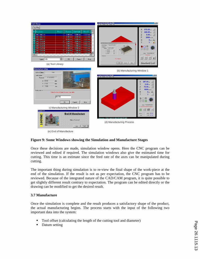
Figure 9: Some Windows showing the Simulation and Manufacture Stages
Once these decisions are made, simulation window opens. Here the CNC program can be
reviewed and edited if required. The simulation windows also give the estimated time for
cutting. This time is an estimate since the feed rate of the axes can be manipulated during
cutting.
The important thing during simulation is to re-view the final shape of the work-piece at the
end of the simulation. If the result is not as per expectation, the CNC program has to be
reviewed. Because of the integrated nature of the CAD/CAM program, it is quite possible to
get slightly different result contrary to expectation. The program can be edited directly or the
drawing can be modified to get the desired result.
3.7 Manufacture
Once the simulation is complete and the result produces a satisfactory shape of the product,
the actual manufacturing begins. The process starts with the input of the following two
important data into the system:
Tool offset (calculating the length of the cutting tool and diameter)
Datum setting
c) Manufacturing Window 2
(a) Tool Library
(d) Manufacturing Process
(e) End of Manufacture
(b) Manufacturing Window 1
Page 26.1115.13

The Boxford software offers tool library that holds the data for the existing tools as shown in
Figure 9 (a). Any tool from the library can be selected and tool offset have been entered
already. Alternatively, a new tool can be added to the library. In that case tool offset need to
be entered into the system.
Since a rectangular plastic block has been selected as the work-piece the machining origin
needs to be defined. This machining origin or datum is the reference point for machining
(also termed as home position). Based on the geometry of the work-piece, front-left corner of
the block is usually taken as datum. Certain steps need to be performed at this stage. The
work-piece needs to be touched using cutting tool first from the left side and then, from the
front-side and finally, from the top surface of the work-piece. Now, the program is ready for
actual cutting of the material.
After setting the datum, the CAM design tool offers ‘manufacture’ option. Once this option is
selected, a new window opens and the data, which have entered already, is displayed on the
screen as shown in Figure 9(b). This is like confirmation message. The software also gives
the option for clamping the work-piece with a vice or any other technique. On choosing the
vice, the software inquires about the height of the work-piece after clamping in the vice as
shown in Figure 9(c).Upon selecting the continuous cycle start buttionmanufacturing
starts.On completion a message saying the manufacture is complete through a screen shown
in Figure 9(e).
3.8 Drilling the Hole, Inserting the Clock and Fixing the Name Tower
Drilling the hole for the clock insert and machining the name block and gluing it to the block
were all important tasks that had to be performed to make the product. However they are
tasks that are familiar. Figure 10 shows the tasks and the finished product.
4Assessing and Evaluating the Work
Generally mathematics in theory will not appeal to everyone. Tutorial classes and office
hours are always packed with students having a variety of questions. But this exercise was an
exception. The students had to finish the conceptual design to start the CorelDraw. There was
only one CorelDraw license and they had to take turns. The students patiently waited for their
turns. Once they were on it they tried various experiments moving the nodal points, moving
the control points and shortening and extending the tangent vectors were some of the
experiments (playing) they did. Every student played with the software. This permitted them
to shape the curve to bring the character. By the time they went for manufacturing every
student was thorough with theory of Bezier curves and how changing something actually
changes the curve. The assessment was divided into four parts the conceptual design,
transferring to CorelDraw and obtaining the Control Points, deriving the mathematical
equation of the curve and the manufacture of the product. Every group and every student did
exceptionally well in the assessments. Figure 11 shows the items produced by all the nine
female groups. The male students made a similar set too. The cohort that came during the
succeeding academic years modelled and produced different products. For example the
cohort in 2012/2013 modelled and manufactured camels while the cohort in 2013/2014 made
falcon badges. The results were similar all the time. The students got full understanding and
ability to use Bezier curves in designs. They could analyse a sketch to break it into suitable
curve segments, evaluate a division for its flexibility and they could synthesize new shapes
that exploit the features of composite Bezier curves.
Page 26.1115.14
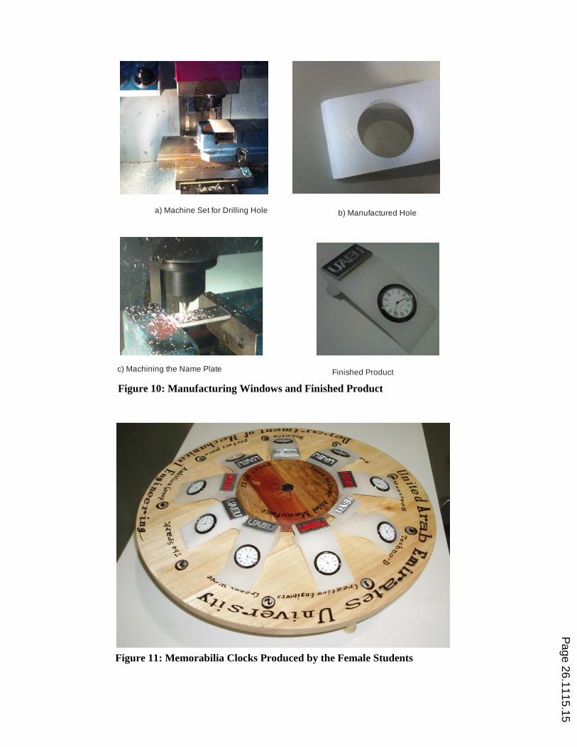
Figure 10: Manufacturing Windows and Finished Product
Figure 11: Memorabilia Clocks Produced by the Female Students
a) Machine Set for Drilling Hole b) Manufactured Hole
c) Machining the Name Plate Finished Product
Page 26.1115.15

5 Learning Experience
Drawing a curve segment in the way the students want was the thrilling experience for them.
Thus the most interesting part in this project was using CorelDraw to draw Bezier curves and
composite curves to model a shape they want. They never had the experience of transferring
a hand-sketch to a computer and this ability gave great excitement. The real power of Bezier
tool in CorelDraw comes from drawing smooth curves.
Writing about a Term Project three years after its completion itself is a testimony for the
strength of the learning experience. The mathematics and its physical realization; Playing
with control points; Tangency condition and its variation; Feeling of Excitement; Team spirit
and confidence experienced; and the achievement itself. These are the memories that were
cherished by the two authors who were students at that time to take part in the project.
6 Conclusions
A methodology that breaks a complex shape into simple curves and straight line segments
and describes the shape as an assemblage of the segments has been developed. The nodal
points, tangency condition and optional intermediate points described the assemblage. This
description was used to transfer the sketch to the computer. CorelDraw software was used to
model the cross section in the computer. This enabled easy manipulation of the control points
and the resulting tangent vectors. The software ‘Boxford CAD/CAM Design Tools V10’
came with the machine was made full use to produce a component having a composite Bezier
curve as its cross section. An effective method to teach Bezier Curves in a practical way has
been demonstrated.
References:
1. http://www.tsplines.com/resources/class_notes/Bezier_curves.pdf accessed on 10th
March 2015.
2. Rabut C., On Pierre Bezier’s life and motivations. Computer Aided Design, 2002, vol.
34, no. ER7, pp. 493-510.
3. Rogers D.F., An Introduction to NURBS: With Historical Perspective, Morgan Kaufman
Publishers, 2001.
4. Farrin G., Curves and Surfaces for Computer Aided Geometric Design, Academic Press,
1988
5. http://www.coreldraw.com/us/product/graphic-design-software/?sso_test=true
Page 26.1115.16