Maintenance Tool For Drive - Toshiba...... Menu bar 3) Command buttons 4) Main 5) Status bar Title...
53
© TOSHIBA Corporation All Rights Reserved. Maintenance Tool For Drive Wi Tool Instruction manual 6F3A4508 Jun, 2002 2002
Transcript of Maintenance Tool For Drive - Toshiba...... Menu bar 3) Command buttons 4) Main 5) Status bar Title...
© TOSHIBA Corporation All Rights Reserved.
Maintenance Tool For Drive
Wi Tool
Instruction manual
6 F 3 A 4 5 0 8
Jun, 2002
2002
TOSHIBA 6F3A4508
- 1 -
W i Tool Operation Description Table of Contents [1] Introduction 2 Before you begin Notes on rewriting drive equipment data Maintenance [2] W i Tool connection 3 [3] Starting W i Tool 6 [4] W i Tool main window 8 [5] W i Tool functions 10 [6] W i Tool function detail description [6-1] Word detail description 11 [6-2] String detail description 14 [6-3] Bit detail description 17 [6-4] Set point control detail description 21 [6-5] Traceback detail description 29 [6-6] Snapshot detail description 36 [6-7] Trend view detail description 38 [6-8] Step response detail description 40 [6-9] Password control detail description 42 [6-10] Property detail description 44 [6-11] Preparation detail description 48 [6-12] Ending detail description 49 [7] W i Tool 1:N connection, 1:N RIO connection 50
p1010074
[1] Introduction 2 Before you begin Notes on rewriting drive equipment data Maintenance [2] Wi Tool connection 3 [3] Starting Wi Tool 6 [4] Wi Tool main window 8 [5] Wi Tool functions 10 [6] Wi Tool function detail description [6-1] Word detail description 11 [6-2] String detail description 14 [6-3] Bit detail description 17 [6-4] Set point control detail description 21 [6-5] Traceback detail description 29 [6-6] Snapshot detail description 36 [6-7] Trend view detail description 38 [6-8] Step response detail description 40 [6-9] Password control detail description 42 [6-10] Property detail description 44 [6-11] Preparation detail description 48 [6-12] Ending detail description 49 [7] Wi Tool 1:N connection, 1:N RIO connection 50
TOSHIBA 6F3A4508
- 2 -
[1] Introduction This document describes the W i Tool which is a tool for the Toshiba Wi Series drive equipment. For information on how to install W i Tool on your PC, refer to the "Installation manual" (6F3A4507). Note that the drive equipment cannot be connected unless the correct connection method and PC settings are used. Be sure to understand the concept of these settings thoroughly. The following topics are described:
Chapter 2: Connection Method Chapter 3: Startup Method Chapter 4: Main Window Description Chapter 5: Function Summary Chapter 6: Function Details Chapter 7: Connection Other than 1:1 Connection
<Before you begin> Microsoft and Toshiba have the Copyrights to this software. Copying this software to unauthorized PC is prohibited. Do not install programs other than the above on your PC. The settings of your PC may be altered causing the W i Tool to slow down or become inoperable. <Notes on rewriting drive equipment data> Observe the following when rewriting the drive equipment data. 1) Rewriting the data may disturb the drive equipment. (For example, if the speed setting is rewritten, the motor speed will change. If the control gain is rewritten, the control system will change causing it to trip or become unstable. ) Be very careful when rewriting. When the motor is running, the message "OK to rewrite while running?" appears on the screen. 2) When rewriting the data, there is a password function on the drive equipment side. If the correct password is not provided, a password error occurs and the data remains unchanged. 3) The setting in the drive equipment is normally written in RAM. W i Tool normally modifies this data in RAM. However, this data in RAM is erased once the power is turned off. Therefore, the drive equipment also holds the settings in EEPROM which is not erased when the power is turned off and the settings are copied to RAM from EEPROM when the power is turned on. When data is changed with the W i Tool, only the data in RAM is changed. Therefore, the settings must be copied from RAM to EEPORM before turning the power off.
<Maintenance> This software is supplied on CD-ROM. Keep it as backup.

TOSHIBA 6F3A4508
- 3 -
[2] Wi Tool connection The following three types of network connections are available for W i Tool: 1) 1:1 connection
PC and drive are connected 1 to 1. Therefore, only one PC and drive equipment are connected to the network.
Figure 2 1:1 connection 2) 1:N connection
Multiple drive equipments are connected to a single PC. Normally, the network is connected through a device called the HUB. In this case, an IP address is required for the PC and each drive unit.
Figure 2 1:N connection
250Wi
Ethernet
Ethernet
Ethernet Hub
T-250Wi
T-250Wi
T-250Wi

TOSHIBA 6F3A4508
- 4 -
3) 1:N RIO connection
This is a connection made via Integrated Controller V Series. The PC is connected to the Integrated Controller network and exchanges messages with the Integrated Controller RIO (Remote I/O Controller). RIO and drive equipment exchange messages using the message transmission function of the Transmission Unit TL-S20. Consequently, the PC exchanges messages with the drive equipment.
In this case, an IP address is required for the PC and each RIO. The drive equipment does not need an IP address because message is exchanged using the TL-S20.
Ethernet
250Wi
TL-S20
250Wi
TL-S20
RIO RIO
ASC ASC
T-250Wi T-250Wi
Figure 2.3 RIO connection
TOSHIBA 6F3A4508
- 5 -
The necessary information, the creation of setup file based on this information, PC setup, and the window display depend on the selected connection method ((1) 1:1, (2) 1:N, or (3) 1:N RIO). Refer to the "Installation manual" (6E3A4507) for details.
4) Connection between PC and drive equipment
The actual connection between the PC and drive equipment is made by an Ethernet cable. (1) In the case of 1:1 connection, connect the TOOL connector on the drive equipment board and the Ethernet connector of the PC with an Ethernet cross cable. The Ethernet cross cable is provided with W i Tool. (2) In the case of 1:N, it is not possible to connect to the drive equipment board. Connect the Ethernet connector of the PC and the hub with an Ethernet straight cable because the signal from the drive equipment is connected to the Ethernet hub. (3) In the case of 1:N RIO connection, connect the Ethernet connector of the PC and the hub with an Ethernet straight cable as with (2) 1:N connection. Cross cable and straight cable are available as Ethernet cable. Note that the correct cable must be used. A single cross cable is included with W i Tool. Straight cables must be purchased separately.

TOSHIBA 6F3A4508
- 6 -
[3] Starting Wi Tool
If installation is finished, W i Tool can be started according to the following procedure: 1) Click the START button at the bottom left corner of the screen. 2) Select Program/TOSHIBA Drive Tools. 3) When W i Tool appears, click it. 4) If TOSHIBA Drive Tools or W i Tool is not displayed:
W i Tool may not be installed.
Install it. Refer to the "Installation manual" (6F3A4507) for details.
Figure 3.1 Starting W i Tool

TOSHIBA 6F3A4508
- 7 -
The following window appears when W i Tool is started.
Figure 3.2 Logon window Enter the User Name and Access Level and then click OK. A password input window appears when connecting to the drive equipment.
Figure 3.3 Password prompt
Enter the password and click OK. <<User Name, Access Level, Password>> The name of the operator allowed to connect to the drive equipment, access level of the operator, and the password for that operator are registered in each drive equipment. This operator name is referred to as the User Name. The access level is divided into ten levels from 0 (Read Only) to 9 (Full Access). If the User Name and Access Level do not match those registered in the drive equipment, the drive equipment returns access level 0. The User Name and Password are set to "TOSHIBA" at factory shipment. Access level 9 is allowed with this user name. This User Name and Access Level are entered when starting W i Tool and are used to connect to the drive equipment.

TOSHIBA 6F3A4508
- 8 -
[4] Wi Tool main window
The main window opens when the password is entered. The standard 1:1 connection windows are described. The main window consists of five main components:
1) Title 2) Menu bar 3) Command buttons 4) Main 5) Status bar
Figure 4.1 Main window
Main
Status bar
Title Menu bar Command buttons
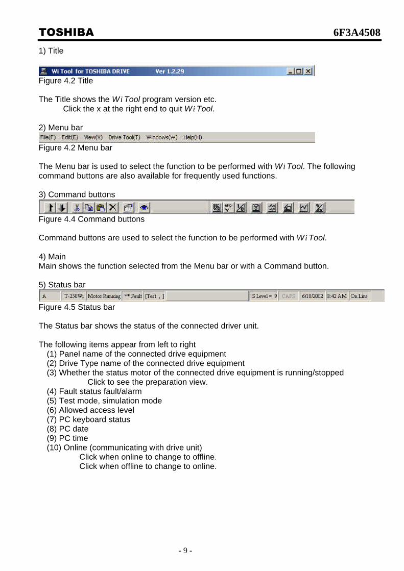
TOSHIBA 6F3A4508
- 9 -
1) Title
Figure 4.2 Title The Title shows the W i Tool program version etc.
Click the x at the right end to quit W i Tool. 2) Menu bar
Figure 4.2 Menu bar The Menu bar is used to select the function to be performed with W i Tool. The following command buttons are also available for frequently used functions.
3) Command buttons
Figure 4.4 Command buttons Command buttons are used to select the function to be performed with W i Tool. 4) Main Main shows the function selected from the Menu bar or with a Command button. 5) Status bar
Figure 4.5 Status bar The Status bar shows the status of the connected driver unit. The following items appear from left to right
(1) Panel name of the connected drive equipment (2) Drive Type name of the connected drive equipment (3) Whether the status motor of the connected drive equipment is running/stopped
Click to see the preparation view. (4) Fault status fault/alarm (5) Test mode, simulation mode (6) Allowed access level (7) PC keyboard status (8) PC date (9) PC time (10) Online (communicating with drive unit)
Click when online to change to offline. Click when offline to change to online.
TOSHIBA 6F3A4508
- 10 -
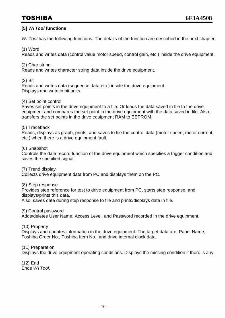
[5] Wi Tool functions W i Tool has the following functions. The details of the function are described in the next chapter. (1) Word Reads and writes data (control value motor speed, control gain, etc.) inside the drive equipment.
(2) Char string Reads and writes character string data inside the drive equipment.
(3) Bit Reads and writes data (sequence data etc.) inside the drive equipment. Displays and write in bit units.
(4) Set point control Saves set points in the drive equipment to a file. Or loads the data saved in file to the drive equipment and compares the set point in the drive equipment with the data saved in file. Also, transfers the set points in the drive equipment RAM to EEPROM.
(5) Traceback Reads, displays as graph, prints, and saves to file the control data (motor speed, motor current, etc.) when there is a drive equipment fault. (6) Snapshot Controls the data record function of the drive equipment which specifies a trigger condition and saves the specified signal. (7) Trend display Collects drive equipment data from PC and displays them on the PC. (8) Step response Provides step reference for test to drive equipment from PC, starts step response, and displays/prints this data. Also, saves data during step response to file and prints/displays data in file. (9) Control password Adds/deletes User Name, Access Level, and Password recorded in the drive equipment. (10) Property Displays and updates information in the drive equipment. The target data are, Panel Name, Toshiba Order No., Toshiba Item No., and drive internal clock data.
(11) Preparation Displays the drive equipment operating conditions. Displays the missing condition if there is any. (12) End Ends W i Tool.

TOSHIBA 6F3A4508
- 11 -
[6] Wi Tool functions detail description [6-1] Word detail description This function loads and writes data (control amount motor speed, control gain, etc.) inside the drive equipment. Select Drive Tool/Data Control/Word from the menu bar
or click the command button
to select. The following window appears.
Figure 6.1.1 Word window
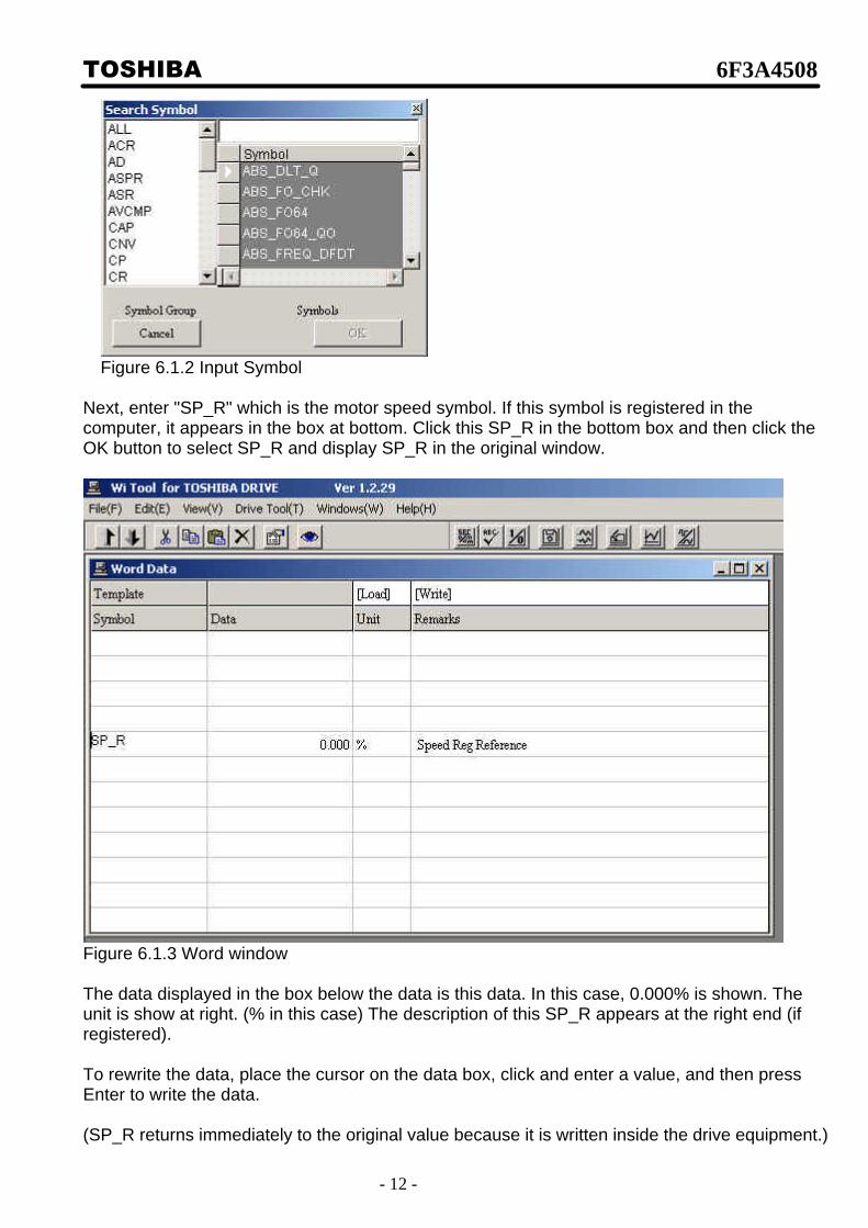
To load the motor speed, first place the cursor on the symbol box on the left side and double click. (You can click any of the 12 lines.) Then the symbol input window appears.
TOSHIBA 6F3A4508
- 12 -
Figure 6.1.2 Input Symbol
Next, enter "SP_R" which is the motor speed symbol. If this symbol is registered in the computer, it appears in the box at bottom. Click this SP_R in the bottom box and then click the OK button to select SP_R and display SP_R in the original window.
Figure 6.1.3 Word window The data displayed in the box below the data is this data. In this case, 0.000% is shown. The unit is show at right. (% in this case) The description of this SP_R appears at the right end (if registered). To rewrite the data, place the cursor on the data box, click and enter a value, and then press Enter to write the data. (SP_R returns immediately to the original value because it is written inside the drive equipment.)

TOSHIBA 6F3A4508
- 13 -
To rewrite the data, refer to "Chapter 1 Notes on Rewriting Drive Equipment Data." Saving and loading template Frequently used symbols can be registered to avoid repeated key entry. This is referred to as template. For example, Speed Reference (SP_R), Motor Speed (SP_F), and Motor Current (I1_F) can be registered by first entering these data and then entering a name by clicking [Write]. Then next time the Word window appears, these symbols can be loaded simply by clicking [Load] and entering the previously specified name.
TOSHIBA 6F3A4508
- 14 -
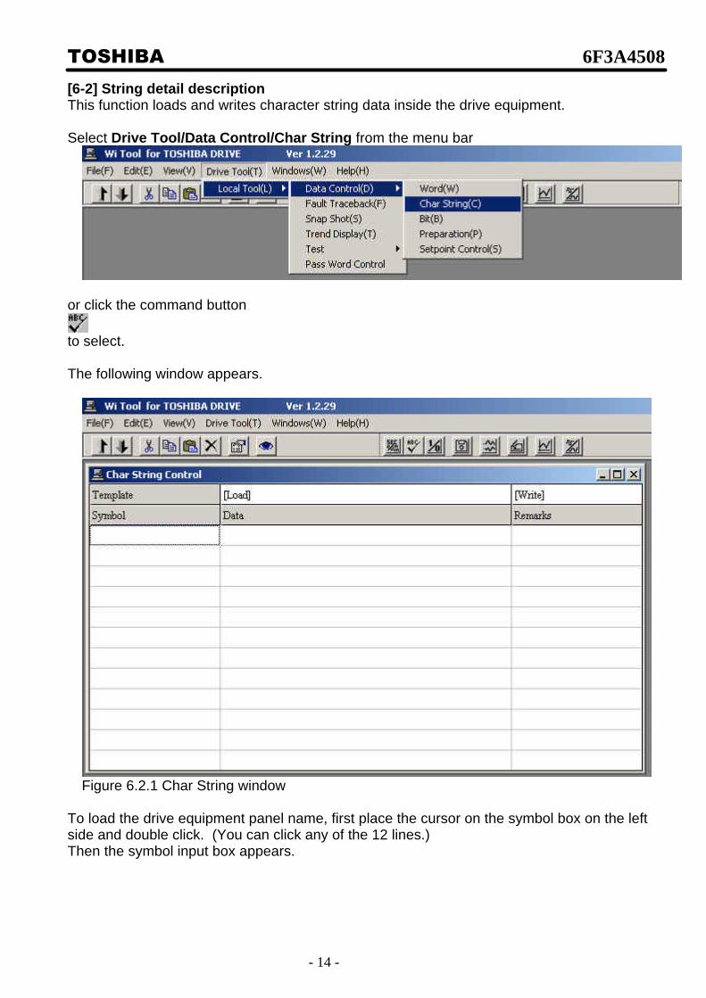
[6-2] String detail description This function loads and writes character string data inside the drive equipment.
Select Drive Tool/Data Control/Char String from the menu bar
or click the command button
to select.
The following window appears.
Figure 6.2.1 Char String window
To load the drive equipment panel name, first place the cursor on the symbol box on the left side and double click. (You can click any of the 12 lines.) Then the symbol input box appears.

TOSHIBA 6F3A4508
- 15 -
Figure 6.1.2 Input Symbol
Then click INF_PANEL which is the drive equipment panel name symbol. The panel name is selected and appears in the window.

TOSHIBA 6F3A4508
- 16 -
Figure 6.2.3 Char String window The data displayed in the box under the data is the Char string data. In this example, it is empty. The description of INF_PANEL appears on the right. To rewrite the data, place the cursor on the data box, click and enter the char string, and then press Enter to write the data.

TOSHIBA 6F3A4508
- 17 -
[6-3] Bit detail description
This function loads and writes data (sequence data etc.) inside the drive equipment. It displays and writes in bit units.
Select Drive Tool/Data Control/Bit from the menu bar
or click the command button
to select. The following window appears.
Figure 6.3.1 Bit window To load the sequence data BLR1, first place the cursor on the ? symbol at the top left box and click. Then the symbol selection list appears.

TOSHIBA 6F3A4508
- 18 -
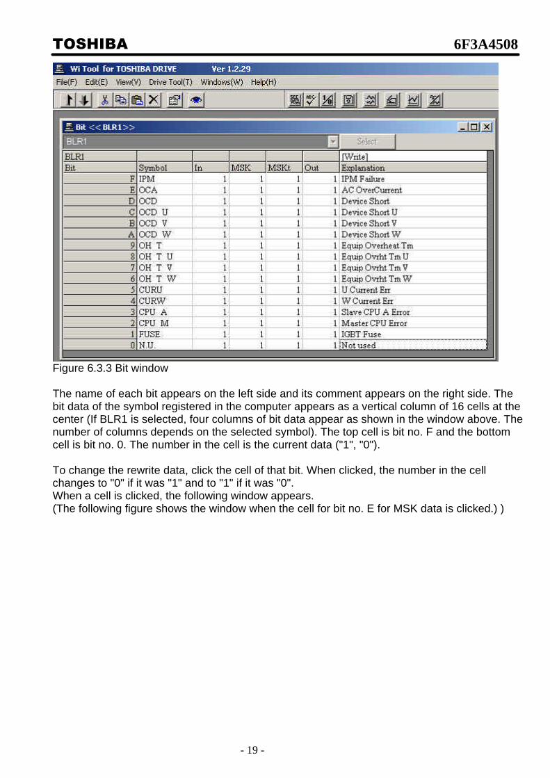
Figure 6.3.2 Symbol selection window Next click BLR1 in the symbol selection list to close the symbol selection list and display BLR1 in the box. Then press the select button to select BLR1 and display its data.
TOSHIBA 6F3A4508
- 19 -
Figure 6.3.3 Bit window The name of each bit appears on the left side and its comment appears on the right side. The bit data of the symbol registered in the computer appears as a vertical column of 16 cells at the center (If BLR1 is selected, four columns of bit data appear as shown in the window above. The number of columns depends on the selected symbol). The top cell is bit no. F and the bottom cell is bit no. 0. The number in the cell is the current data ("1", "0"). To change the rewrite data, click the cell of that bit. When clicked, the number in the cell changes to "0" if it was "1" and to "1" if it was "0". When a cell is clicked, the following window appears. (The following figure shows the window when the cell for bit no. E for MSK data is clicked.) )
TOSHIBA 6F3A4508
- 20 -
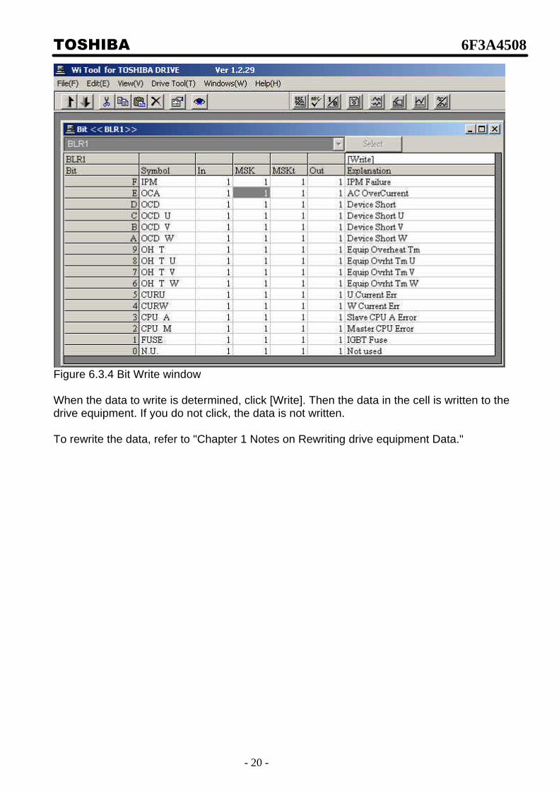
Figure 6.3.4 Bit Write window When the data to write is determined, click [Write]. Then the data in the cell is written to the drive equipment. If you do not click, the data is not written. To rewrite the data, refer to "Chapter 1 Notes on Rewriting drive equipment Data."

TOSHIBA 6F3A4508
- 21 -
[6-4] Set point control detail description This function saves set points in the drive equipment to a file or loads the data saved in file to the drive equipment and compares the set point in the drive equipment with the data saved in file. It also, transfers the set points in the drive equipment RAM to EEPROM.
Select Drive Tool/Data Control/Setpoint Control from the menu bar
or click the command button
to select. The following window appears.
[Note] Your access level must be 9 in order to write set points to the drive equipment. The value in the set point file can be written to the drive equipment only when you login with access level 9 when starting W i Tool.

TOSHIBA 6F3A4508
- 22 -
Figure 6.4.1 Set Point Control
The set points in the drive equipment are processed together. The set points in the drive equipment are in internal RAM. The internal RAM is saved in EEPROM because it is erased when the power is turned off. (Normally EEPROM0 is used.) When the drive equipment power is turned on, the set points in EEPROM are copied to internal RAM. When a value in internal RAM is changed (when set point is rewritten or the set point file is written in the drive equipment), the data in internal RAM must be transferred to EEPROM.

TOSHIBA 6F3A4508
- 23 -
The main functions are: 1) Display set points in drive equipment internal RAM 2) Display set points in drive equipment EEPROM 3) Display set point file 4) Compare drive equipment internal RAM with EEPROM 5) Compare drive equipment internal RAM with set point file 6) Compare drive equipment EEPROM with set point file 7) Transfer set points in drive equipment RAM to EEPROM 8) Write data in drive equipment internal RAM to set point file 9) Write data in drive equipment internal EEPROM to set point file 10) Load set point file to drive equipment internal RAM 11) Compare set point file with set point file
Figure 6.4.2 Set Point Control
(1) (2)
(3)
(4)
(5)
(6)
(8)
(7)
(9)
(10)
(11)

TOSHIBA 6F3A4508
- 24 -
These functions are described below. 1) Display set points in drive equipment internal RAM Click the Data Display button (1). Set point data is read from the drive equipment and displayed as follows:
Figure 6.4.3 RAM display
In W i Tool, some representative set points are maintained as template and the actual set points of the drive equipment are referenced as the difference from the number of this template and the template. In the above example, the template number is 0 and the values different from this template appear below. You can print this data by clicking Print. 2) Display set points in drive equipment EEPROM Click the Data Display button (2). Set point data is read from the drive equipment and displayed. 3) Display set point file Click the Select File button (3). Select a set point file and then click Show File Data below button (3). The content of the file is displayed.

TOSHIBA 6F3A4508
- 25 -
4) Compare drive equipment internal RAM with EEPROM Click arrow (4).
Figure 6.4.4
The Start Compare with EEPROM button appears at bottom left of the window. Click this to start compare and display the result.

TOSHIBA 6F3A4508
- 26 -
Figure 6.4.5 Set Point Compare
5) Compare drive equipment internal RAM with set point file First, select a set point file. Click the Select File (3) button and select a set point file. Then click arrow (5) to display the Compare File button at bottom left of the screen and click this button to start compare. The result is displayed when compare is finished. 6) Compare drive equipment EEPROM with set point file First, select a set point file. Click the Select File (3) button and select a set point file. Then click arrow (6) to display the Start Compare with EEPROM button at bottom left of the screen and click this button to start compare. The result is displayed when compare is finished. 7) Transfer set points in drive equipment RAM to EEPROM Click arrow (7) to display the following window.

TOSHIBA 6F3A4508
- 27 -
Figure 6.4.6 Write EEPROM
A new EEPROM comment appears. Enter the comment (up to 32 characters) to write in EEPROM and then click the Write EEPROM button that appears at bottom left of the window to start transfer to EEPROM. 8) Write data in drive equipment internal RAM to set point file First, select a set point file. Click the Select File (3) button and select a set point file. Then click arrow (8) to display the Save to File button at bottom left of the screen and click this button to start write to file. 9) Write data in drive equipment internal EEPROM to set point file First, select a set point file. Click the Select File (3) button and select a set point file. Then click arrow (9) to display the Save EEPROM button at bottom left of the screen and click this button to start write to file.

TOSHIBA 6F3A4508
- 28 -
10) Load set point file to drive equipment internal RAM First, select a set point file. Click the Select File (3) button and select a set point file. Then click arrow (10) to display the Load from File button at bottom left of the screen and click this button to start load to file. 11) Compare set point file with set point file First, select the first set point file. Click the Select File (3) button and select a set point file. Then select the second set point file. Click the Select File button below arrow (11) and select a set point file. Then click arrow (11) to display the Compare File button at bottom left of the screen and click this button to start compare.
TOSHIBA 6F3A4508
- 29 -
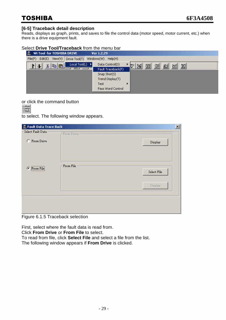
[6-5] Traceback detail description Reads, displays as graph, prints, and saves to file the control data (motor speed, motor current, etc.) when there is a drive equipment fault. Select Drive Tool/Traceback from the menu bar
or click the command button
to select. The following window appears.
Figure 6.1.5 Traceback selection First, select where the fault data is read from. Click From Drive or From File to select. To read from file, click Select File and select a file from the list. The following window appears if From Drive is clicked.

TOSHIBA 6F3A4508
- 30 -
Figure 6.5.2 Fault selection This list contains a list of fault data in the drive equipment. (Up to 16 faults) Click the down arrow to display the data list and click an item to select. Then click the Display button. The data is read and displayed as graph.

TOSHIBA 6F3A4508
- 31 -
Figure 6.5.3 Traceback window When data read completes, a graph similar to the one above appears. Control data is obtained with different sampling data depending on the drive equipment and a graph is displayed for each sampling data. Click the Option tab on the graph to display the following window.

TOSHIBA 6F3A4508
- 32 -
Figure 6.5.4 Traceback print Then click the Write button to save this data to file with the specified file name. You can also click the Print button to print this data. In addition to the graph, the detected fault signals (first faults) are also displayed.
TOSHIBA 6F3A4508
- 33 -
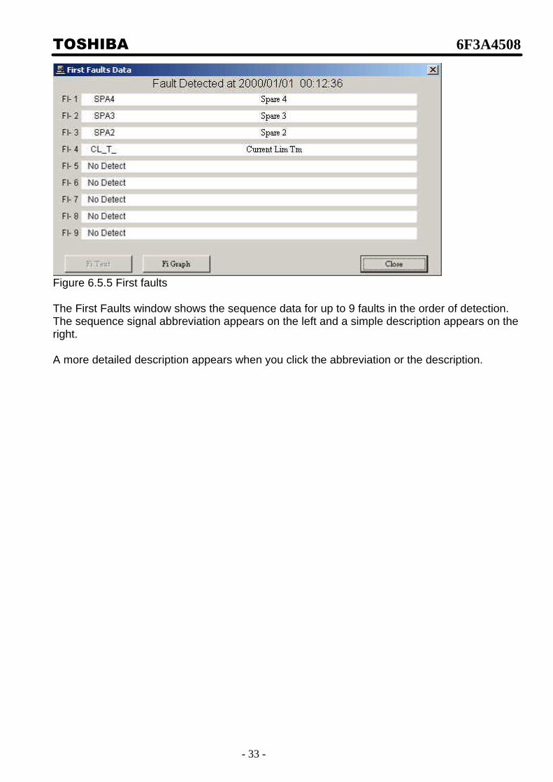
Figure 6.5.5 First faults The First Faults window shows the sequence data for up to 9 faults in the order of detection. The sequence signal abbreviation appears on the left and a simple description appears on the right. A more detailed description appears when you click the abbreviation or the description.

TOSHIBA 6F3A4508
- 34 -
Next, click the Setting tab on the graph to change the graph settings.
Figure 6.5.6 Select traceback signal 1) The number at top center is the number of graphs per window. You can select 1, 2, 4, 8, or 12 signals per window. 2) The Signal name displayed on the graph appears on the left side. Click a signal name to change it.
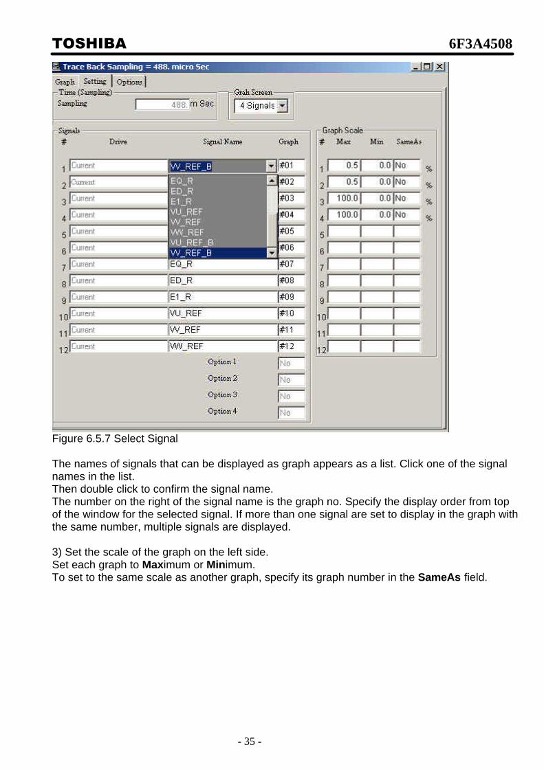
TOSHIBA 6F3A4508
- 35 -
Figure 6.5.7 Select Signal The names of signals that can be displayed as graph appears as a list. Click one of the signal names in the list. Then double click to confirm the signal name. The number on the right of the signal name is the graph no. Specify the display order from top of the window for the selected signal. If more than one signal are set to display in the graph with the same number, multiple signals are displayed. 3) Set the scale of the graph on the left side. Set each graph to Maximum or Minimum. To set to the same scale as another graph, specify its graph number in the SameAs field.

TOSHIBA 6F3A4508
- 36 -
[6-6] Snapshot detail description
This function controls the data record function of the drive equipment which specifies a trigger condition and saves the specified signal.
The difference with traceback described above is that whereas the trigger condition of traceback is limited to faults, the user can set the trigger condition freely with snapshot. Also there is a difference in the number of saved signals (up to 60 signals for traceback and 8 signals for snapshot) and the number of samples that can be saved (up to 512 samples for traceback and up to 1024 signals for snapshot).
Select Drive Tool/Local Tool/Snap Shot from the menu bar
or click the command button
to select. The following window appears.
Figure 6.6.1 Snapshot
Set the snapshot condition in this window. 1) Number of Signals: Specify the number of signals to save. For snapshot, you can select from
2 signals 1024 samples

TOSHIBA 6F3A4508
- 37 -
4 signals 512 samples 8 signals 256 samples
2) Signal Name: Specify the saved signal name. Click a signal name to display a list of selectable signal names. Then select a name from the list and double click to confirm. 3) Select Hi Speed/STD Speed sampling time Click STD Speed to select standard sampling speed Click Hi Speed to select High sampling speed Normally, select standard sampling (1mSec). With high speed sampling, there is a restriction on the selectable signal names. Whether standard sampling or high speed sampling is currently selected is displayed below. 4) Trigger condition In the window on the previous page, trigger conditions where:
(1) Trigger signal 0x0000 (2) Trigger mode Boolean (3) Trigger type Level Trigger (4) Trigger bit "0" (5) Pre-trigger "0"
In other words data save start when there is a level trigger with the 0th bit of signal 0x0000 set to 1.
The following trigger modes are available: Trigger when Boolean bit signal is 1 (specify the bit with the trigger bit) Trigger when Inverted Boolean bit signal is 0 (specify the bit with the trigger bit) Trigger when "equal" signal is at trigger level Trigger when "Not equal" signal is different from trigger level Trigger when "Greater Than" signal is greater than trigger level Trigger when "Less Than" signal is less than trigger level The following trigger types are available: Trigger when edge trigger signal changes Trigger at level trigger signal level Setting the time Set to full scale (time from end to end of the window). Also set the re-enable time. Re-enable time is the time until trigger becomes ready after there is a trigger. (Normally, this is not used. To use, check Re-Enable.) Status display Displays the current status. (1) Data Empty: Status when there is no data. (2) Data Triggered: Triggered status. (3) Trigger Ready: Waiting for a trigger. Normally, the trigger condition and signal name are set during Data Empty status and the Set Trigger button is clicked to enter the Trigger Ready status. The button becomes Reset Trigger. When there is a trigger, the status becomes Data Triggered and the Display button is enabled. At this point, click the Display button to display the graph.

TOSHIBA 6F3A4508
- 38 -
[6-7] Trend view detail description This function collects drive equipment data from the PC and displays them on the PC. Select Drive Tool/Local Tool/Trend Display from the menu bar
or click the command button
to select. The following window appears.
Figure 6.7.1 Trend setup window

TOSHIBA 6F3A4508
- 39 -
This window is similar to the traceback graph. However, in the case of Trend Display, the user must specify the signal to display. Also, the user must set the graph scale. In addition, the sampling time must be set in Trend Display. (Minimum is 50mSec.) Set these items and click the Graph tab to display the following window.
Figure 6.7.2 Trend graph
There is a Start button at bottom left of the graph. Click this button to start the Trend Display. Click the same button to stop the graph display (button is changed to Stop ). When clicking the Setting tab once more, to change the signal to display for example, stop the graph display before clicking.

TOSHIBA 6F3A4508
- 40 -
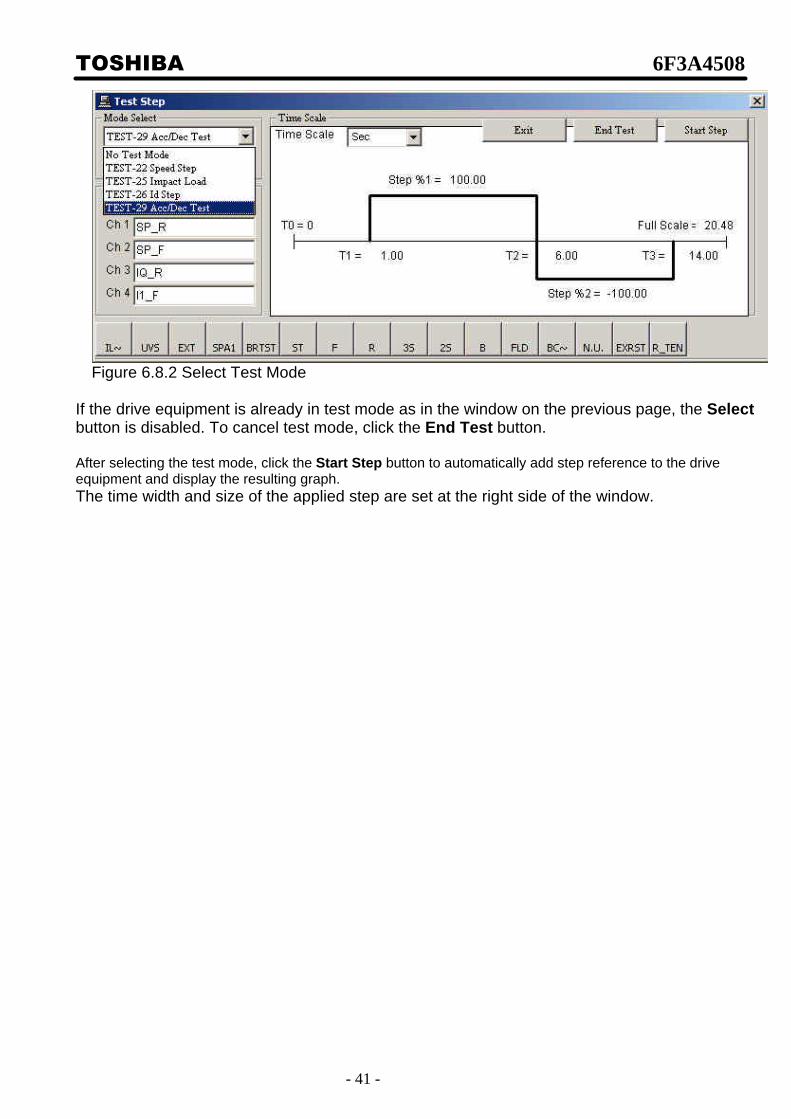
[6-8] Step response detail description
This function provides step reference for test to drive equipment from PC, starts step response, and displays/prints this data. It also, saves data during step response to file and prints/displays data in the file.
Select Drive Tool/Local Tool/Test/Step Response from the menu bar
or click the command button
to select. The following window appears.
Figure 6.8.1 Step response First, determine which test mode to select. Click the Mode Select down arrow and select a mode.
TOSHIBA 6F3A4508
- 41 -
Figure 6.8.2 Select Test Mode
If the drive equipment is already in test mode as in the window on the previous page, the Select button is disabled. To cancel test mode, click the End Test button. After selecting the test mode, click the Start Step button to automatically add step reference to the drive equipment and display the resulting graph. The time width and size of the applied step are set at the right side of the window.
TOSHIBA 6F3A4508
- 42 -
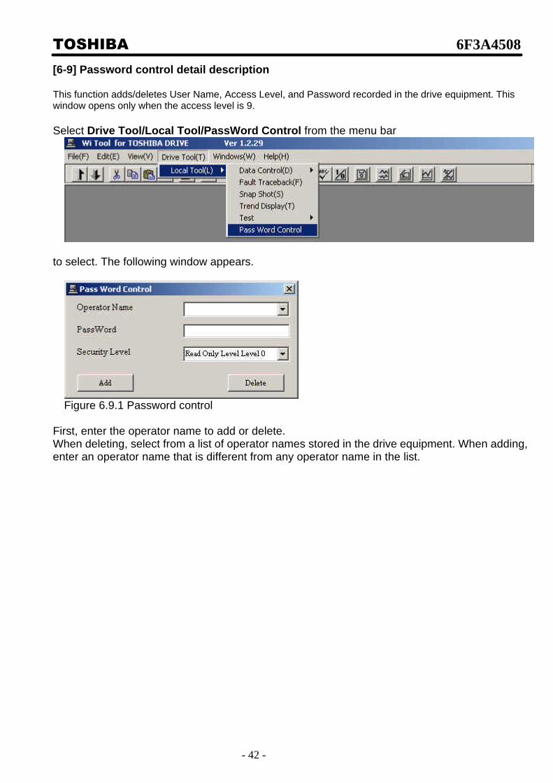
[6-9] Password control detail description This function adds/deletes User Name, Access Level, and Password recorded in the drive equipment. This window opens only when the access level is 9. Select Drive Tool/Local Tool/PassWord Control from the menu bar
to select. The following window appears.
Figure 6.9.1 Password control
First, enter the operator name to add or delete. When deleting, select from a list of operator names stored in the drive equipment. When adding, enter an operator name that is different from any operator name in the list.

TOSHIBA 6F3A4508
- 43 -
Then enter the password and security level if entering an operator name. These are not necessary when deleting. Click the Add or Delete button to display the following window.
Figure 6.9.2 Password control verification
Click OK to execute. Note that if you delete all operators with security level 9, you will not be able to add passwords.

TOSHIBA 6F3A4508
- 44 -
[6-10] Property detail description This function displays and updates information in the drive equipment. The target data are, Panel Name, Toshiba Order No., Toshiba Item No., and drive internal clock data. Select File/Property from the menu bar
or click the command button
to select. The following window appears.
Figure 6.10.1 Drive property
This window displays the Panel Name, Drive Type, Data Base Version, Toshiba Order Number, Item Number, and Tag of the drive equipment. The Panel Name, Toshiba Order Number, Item Number, and Tag are rewritable. To rewrite, click the item to change, enter the new item, and then click the Write button.
TOSHIBA 6F3A4508
- 45 -
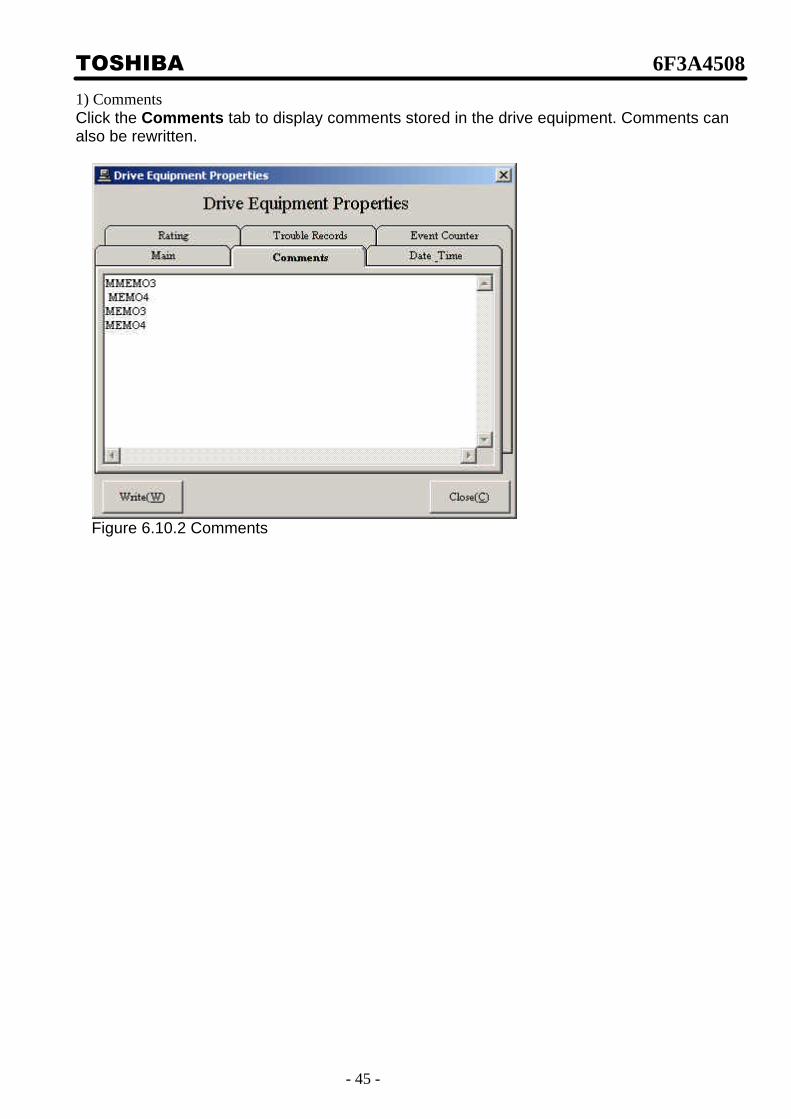
1) Comments Click the Comments tab to display comments stored in the drive equipment. Comments can also be rewritten.
Figure 6.10.2 Comments

TOSHIBA 6F3A4508
- 46 -
2) Setting time Click the Date_Time tab to display the drive equipment time and the current time (of the PC). Click Set Current Time to synchronize the drive equipment time with the PC time.
Figure 6.10.3 Time
3) Rating Click the Rating tab to display the drive equipment and motor rating. This window is read only.
Figure 6.10.4 Rating
TOSHIBA 6F3A4508
- 47 -
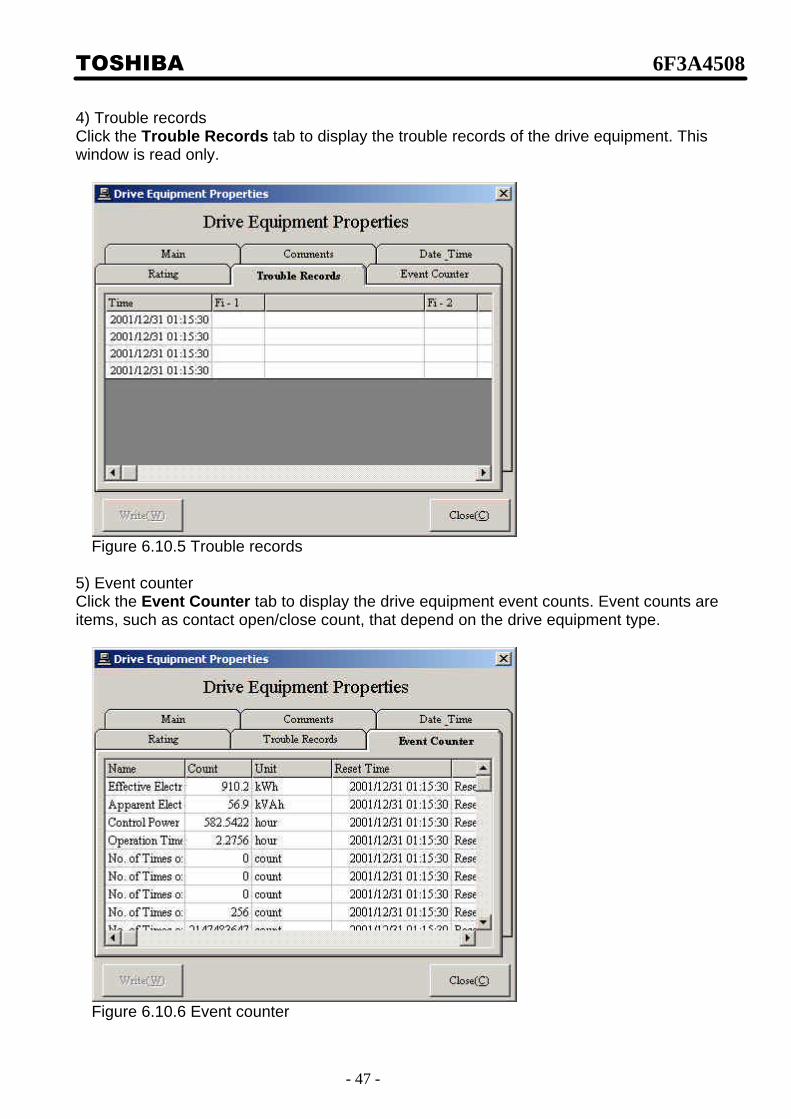
4) Trouble records Click the Trouble Records tab to display the trouble records of the drive equipment. This window is read only.
Figure 6.10.5 Trouble records
5) Event counter Click the Event Counter tab to display the drive equipment event counts. Event counts are items, such as contact open/close count, that depend on the drive equipment type.
Figure 6.10.6 Event counter

TOSHIBA 6F3A4508
- 48 -
[6-11] Preparation detail description This function displays the drive equipment operating conditions. It displays the missing condition if there is any. Select Drive Tool/Local Tool/Data Control/ Preparation from the menu bar
or click Fault/Alarm drive status display on the status bar
to select. The following window appears.
Figure 6.11.1 Preparation Click Fault Reset in this window to reset faults.

TOSHIBA 6F3A4508
- 49 -
[6-12] Ending detail description
Click x at top right of the main window to end W i Tool. The following window appears. If set points are changed, but not transferred to EEPROM, click Cancel and transfer the set points to EEPROM.
Figure 6.12.1 Ending

TOSHIBA 6F3A4508
- 50 -
[7] Wi Tool 1:N connection, 1:N RIO connection [1:N connection] The following window appears when W i Tool is started after connecting to the drive equipment by 1:N connection via Ethernet.
Figure 7.1 1:N connection The network connection appears on the left side of the window. Click the drive equipment name in this network connection to connect to that drive equipment.
Figure 7.2 Connect Drive After connecting the drive equipment, functions similar to 1:1 connection become available.

TOSHIBA 6F3A4508
- 51 -
[1:N RIO connection] The following window appears when W i Tool is started after connecting to the drive equipment by 1:N connection through RIO (remote I/O).
Figure 7.3 RIO connection The network connection appears on the left side of the window. Click the drive equipment name in the same manner as Ethernet connection to connect to that drive unit.