MAINTENANCE SCHEDULE FAULT FINDING … SCHEDULE & FAULT FINDING CHECK LIST Air-bleed Pneumatic...
16
MAINTENANCE SCHEDULE & FAULT FINDING CHECK LIST Air-bleed Pneumatic System- fault finding. Air bleed & Pressure Applied-cicuits-elec/pne. Sensitive Edge-check list. Service & Maintenance Guide. CONTACT DETAILS: Address: 43 Broton Drive, Halstead, Essex, CO9 1HB Tel: 01787 473000 Fax: 01787 477040 Email: [email protected] Internet: www.transportdoorsolutions.co.uk
-
Upload
nguyenkhue -
Category
Documents
-
view
231 -
download
2
Transcript of MAINTENANCE SCHEDULE FAULT FINDING … SCHEDULE & FAULT FINDING CHECK LIST Air-bleed Pneumatic...

MAINTENANCE SCHEDULE
&
FAULT FINDING CHECK LIST
Air-bleed Pneumatic System- fault finding. Air bleed & Pressure Applied-cicuits-elec/pne.
Sensitive Edge-check list. Service & Maintenance Guide.
CONTACT DETAILS:
Address: 43 Broton Drive, Halstead, Essex, CO9 1HB Tel: 01787 473000 Fax: 01787 477040
Email: [email protected] Internet: www.transportdoorsolutions.co.uk
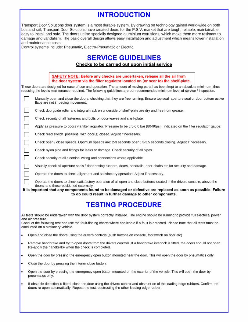
INTRODUCTION Transport Door Solutions door system is a most durable system. By drawing on technology gained world-wide on both bus and rail, Transport Door Solutions have created doors for the P.S.V. market that are tough, reliable, maintainable, easy to install and safe. The doors utilise specially designed aluminium extrusions, which make them more resistant to damage and vandalism. The basic overall design allows easy installation and adjustment which means lower installation and maintenance costs. Control systems include: Pneumatic, Electro-Pneumatic or Electric.
SERVICE GUIDELINES Checks to be carried out upon initial service
These doors are designed for ease of use and operation. The amount of moving parts has been kept to an absolute minimum, thus reducing the levels maintenance required. The following guidelines are our recommended minimum level of service / inspection.
Manually open and close the doors, checking that they are free running. Ensure top seal, aperture seal or door bottom active flaps are not impeding movement. Check doorguide roller and integral track on underside of shelf-plate are dry and free from grease. Check security of all fasteners and bolts on door-leaves and shelf-plate. Apply air pressure to doors via filter regulator. Pressure to be 5.5-6.0 bar (80-90psi). Indicated on the filter regulator gauge. Check reed switch positions, with door(s) closed. Adjust if necessary. Check open / close speeds. Optimum speeds are: 2-3 seconds open ; 3-3.5 seconds closing. Adjust if necessary. Check nylon pipe and fittings for leaks or damage. Check security of all pipes. Check security of all electrical wiring and connections where applicable. Visually check all aperture seals / door nosing rubbers, doors, handrails, door-shafts etc for security and damage. Operate the doors to check alignment and satisfactory operation. Adjust if necessary. Operate the doors to check satisfactory operation of all open and close buttons located in the drivers console, above the doors, and those positioned externally.
It is important that any components found to be damaged or defective are replaced as soon as possible. Failure to do could result in further damage to other components.
TESTING PROCEDURE All tests should be undertaken with the door system correctly installed. The engine should be running to provide full electrical power and air pressure. Conduct the following test and use the fault-finding charts where applicable if a fault is detected. Please note that all tests must be conducted on a stationary vehicle. • Open and close the doors using the drivers controls (push buttons on console, footswitch on floor etc) • Remove handbrake and try to open doors from the drivers controls. If a handbrake interlock is fitted, the doors should not open.
Re-apply the handbrake when the check is completed. • Open the door by pressing the emergency open button mounted near the door. This will open the door by pneumatics only. • Close the door by pressing the interior close button. • Open the door by pressing the emergency open button mounted on the exterior of the vehicle. This will open the door by
pneumatics only. • If obstacle detection is fitted, close the door using the drivers control and obstruct on of the leading edge rubbers. Confirm the
doors re-open automatically. Repeat the test, obstructing the other leading edge rubber.
SAFETY NOTE: Before any checks are undertaken, release all the air from the door system via the filter regulator located on (or near to) the shelf-plate.
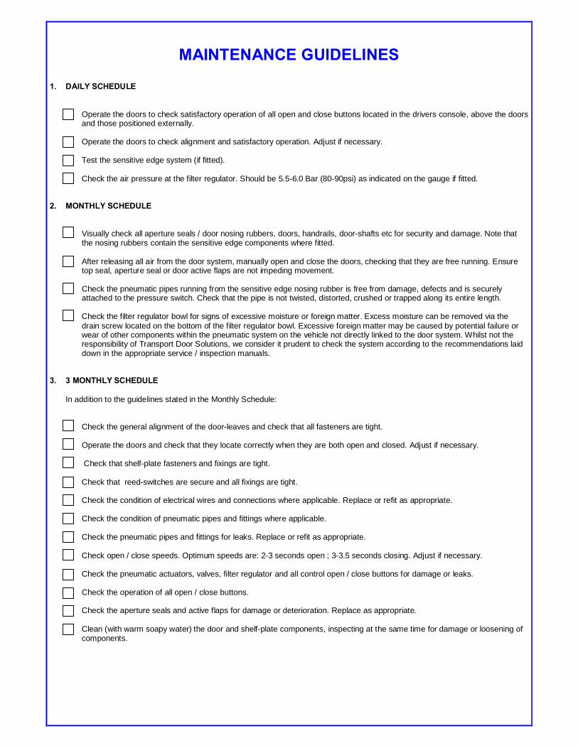
MAINTENANCE GUIDELINES
1. DAILY SCHEDULE
Operate the doors to check satisfactory operation of all open and close buttons located in the drivers console, above the doors and those positioned externally.
Operate the doors to check alignment and satisfactory operation. Adjust if necessary.
Test the sensitive edge system (if fitted). Check the air pressure at the filter regulator. Should be 5.5-6.0 Bar (80-90psi) as indicated on the gauge if fitted.
2. MONTHLY SCHEDULE
Visually check all aperture seals / door nosing rubbers, doors, handrails, door-shafts etc for security and damage. Note that the nosing rubbers contain the sensitive edge components where fitted. After releasing all air from the door system, manually open and close the doors, checking that they are free running. Ensure top seal, aperture seal or door active flaps are not impeding movement. Check the pneumatic pipes running from the sensitive edge nosing rubber is free from damage, defects and is securely attached to the pressure switch. Check that the pipe is not twisted, distorted, crushed or trapped along its entire length. Check the filter regulator bowl for signs of excessive moisture or foreign matter. Excess moisture can be removed via the drain screw located on the bottom of the filter regulator bowl. Excessive foreign matter may be caused by potential failure or wear of other components within the pneumatic system on the vehicle not directly linked to the door system. Whilst not the responsibility of Transport Door Solutions, we consider it prudent to check the system according to the recommendations laid down in the appropriate service / inspection manuals.
3. 3 MONTHLY SCHEDULE
In addition to the guidelines stated in the Monthly Schedule:
Check the general alignment of the door-leaves and check that all fasteners are tight. Operate the doors and check that they locate correctly when they are both open and closed. Adjust if necessary. Check that shelf-plate fasteners and fixings are tight. Check that reed-switches are secure and all fixings are tight. Check the condition of electrical wires and connections where applicable. Replace or refit as appropriate. Check the condition of pneumatic pipes and fittings where applicable. Check the pneumatic pipes and fittings for leaks. Replace or refit as appropriate. Check open / close speeds. Optimum speeds are: 2-3 seconds open ; 3-3.5 seconds closing. Adjust if necessary. Check the pneumatic actuators, valves, filter regulator and all control open / close buttons for damage or leaks. Check the operation of all open / close buttons. Check the aperture seals and active flaps for damage or deterioration. Replace as appropriate. Clean (with warm soapy water) the door and shelf-plate components, inspecting at the same time for damage or loosening of components.
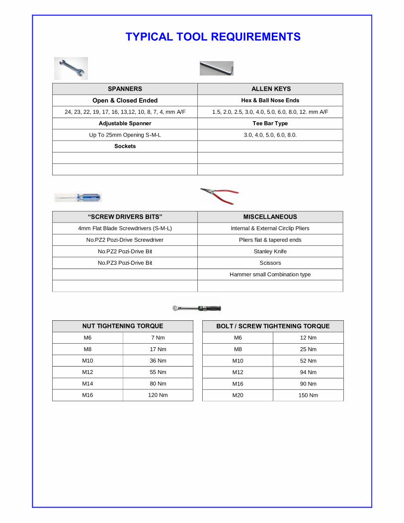
TYPICAL TOOL REQUIREMENTS
SPANNERS ALLEN KEYS
Open & Closed Ended Hex & Ball Nose Ends
24, 23, 22, 19, 17, 16, 13,12, 10, 8, 7, 4, mm A/F 1.5, 2.0, 2.5, 3.0, 4.0, 5.0, 6.0, 8.0, 12. mm A/F
Adjustable Spanner Tee Bar Type
Up To 25mm Opening S-M-L 3.0, 4.0, 5.0, 6.0, 8.0.
Sockets
“SCREW DRIVERS BITS” MISCELLANEOUS
4mm Flat Blade Screwdrivers (S-M-L) Internal & External Circlip Pliers
No.PZ2 Pozi-Drive Screwdriver Pliers flat & tapered ends
No.PZ2 Pozi-Drive Bit Stanley Knife
No.PZ3 Pozi-Drive Bit Scissors
Hammer small Combination type
NUT TIGHTENING TORQUE
M6 7 Nm
M8 17 Nm
M10 36 Nm
M12 55 Nm
M14 80 Nm
M16 120 Nm
BOLT / SCREW TIGHTENING TORQUE
M6 12 Nm
M8 25 Nm
M10 52 Nm
M12 94 Nm
M16 90 Nm
M20 150 Nm
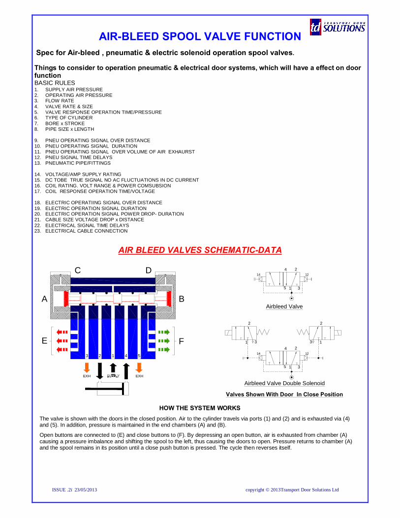
AIR-BLEED SPOOL VALVE FUNCTION
Spec for Air-bleed , pneumatic & electric solenoid operation spool valves. Things to consider to operation pneumatic & electrical door systems, which will have a effect on door function BASIC RULES 1. SUPPLY AIR PRESSURE 2. OPERATING AIR PRESSURE 3. FLOW RATE 4. VALVE RATE & SIZE 5. VALVE RESPONSE OPERATION TIME/PRESSURE 6. TYPE OF CYLINDER 7. BORE x STROKE 8. PIPE SIZE x LENGTH 9. PNEU OPERATING SIGNAL OVER DISTANCE 10. PNEU OPERATING SIGNAL DURATION 11. PNEU OPERATING SIGNAL OVER VOLUME OF AIR EXHAURST 12. PNEU SIGNAL TIME DELAYS 13. PNEUMATIC PIPE/FITTINGS 14. VOLTAGE/AMP SUPPLY RATING 15. DC TOBE TRUE SIGNAL NO AC FLUCTUATIONS IN DC CURRENT 16. COIL RATING. VOLT RANGE & POWER COMSUBSION 17. COIL RESPONSE OPERATION TIME/VOLTAGE 18. ELECTRIC OPERATIING SIGNAL OVER DISTANCE 19. ELECTRIC OPERATION SIGNAL DURATION 20. ELECTRIC OPERATION SIGNAL POWER DROP- DURATION 21. CABLE SIZE VOLTAGE DROP x DISTANCE 22. ELECTRICAL SIGNAL TIME DELAYS 23. ELECTRICAL CABLE CONNECTION
AIR BLEED VALVES SCHEMATIC-DATA
HOW THE SYSTEM WORKS The valve is shown with the doors in the closed position. Air to the cylinder travels via ports (1) and (2) and is exhausted via (4) and (5). In addition, pressure is maintained in the end chambers (A) and (B).
Open buttons are connected to (E) and close buttons to (F). By depressing an open button, air is exhausted from chamber (A) causing a pressure imbalance and shifting the spool to the left, thus causing the doors to open. Pressure returns to chamber (A) and the spool remains in its position until a close push button is pressed. The cycle then reverses itself.
C D
BA
3 2 1 4 5
FE
EXH EXH
1 35
4 214 12
2
3 1
1 35
4 214 12
31
2
Airbleed Valve Double Solenoid
Airbleed Valve
Valves Shown With Door In Close Position
ISSUE .2– 23/05/2013 copyright © 2013Transport Door Solutions Ltd

INST-013-11
SENSITIVE EDGE PRESSURE SWITCH Fault finding check list
1a Check electrical single from pressure switch by shorting out contacts with door in open Position, either relay will energize and solenoid will activate. 1. A1. Check silver pipe is connected to lower port on pressure switch see fig.1
No response. 1. A2. Check operation of spool valve, open/close door electrically & pneumatic vie buttons
No response 1. A3. Use manual over rides on spool valve to check operation of valve see fig.3
No response 1. A4. Check air pressure 2a.Check for power (pos & neg) supplies to coils and relay. Repeat 1a. 2b.Check relay operation by neg feed to (-) No 1. When active will illuminate 2c Check pressure switch by pulsing air into lower port see fig.1 3a Check sensitive edge with door in open position remove pipe (silver).from pressure switch,
Depress nosing rubber and a small puff of air will exhaust from pipe. Need to place pipe Against cheek or wet end to indicate air signal.
No response. 3. A1. Check silver pipe from pressure switch to nosing rubber for kinking 3. A2. Check for cuts or holes in nosing rubber 3. A3. Check for top & bottom bungs are in place and not leaking by soapy water over end and
Then depress nosing rubber. If bubbles appear reseal end with mastic 4a Circuit drawing=PWL303. REV.1. 5 Sensitivity of sensitive edge system Above 5kph (3mph) sensitive edge normally isolated. So edge can’t be activated to open doors. 5. A If doors open on their own when fully close and below 5kph the sensitive edge may be too Sensitive and activating from vibration of vehicle. 5.A1 Detection of sensitive edge is too LIGHT requires adjustment as shown in Fig.2. 5.B If doors open just when doors are fully closed. 5B.1 Nosing rubbers on leading edge of doors are too close and are compressing together sending Signal to open doors. Require door adjustment. 5C when doors go to close from fully open position and re-open before closing. 5C.1 Bottom edge of leading nosing rubbers are catching, rubbing on step, floor or an obstruction. Rubbers require adjusting to give clearance on door travel, Remove obstruction
FIT TUBE TO LOWER PORT FOR “RISING PRESSURE DETECTION”
ADJUSTING SCREW CLOCKWISE=HEAVY DETECTION ANTI-CLOCKWISE=LIGHT DETECTION
S
FIG.1 FIG.2 FIG.3
OVER RIDE BUTTONS
B
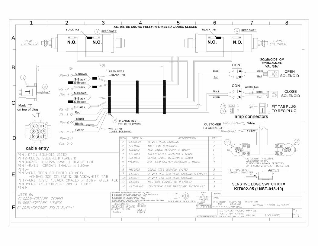
1 2 3 4 5 6 7 8
A
C
D
E
F
T
REED SWT.1REED SWT.2
3x CABLE TIESFITTED AS SHOWN
S-Brown
S-Black
BLACK TAB
BLACK TABREED SWT.2
WHITE TABCLOSE SOLENOID
Green
Red
Black
Black
OPENSOLENOID
WHITE TAB
Red
Black
Green
Black
Red
Black
Red
Black
CON
CON
SOLENOIDS ONSPOOLVALVE
VAL102U
CLOSESOLENOID
amp connectors
FIT TAB PLUGTO REC PLUG
ACTUATOR SHOWN FULLY RETRACTED. DOORS CLOSED
S-Brown
S-Black
BLACK TAB
N.C. N.C. N.C. N.C.
REQUIRE 1.2mmALEEN KEY
S-Brown
S-Black
S-Brown
S-Black
cable entry
Mark "T"on top of plug
T
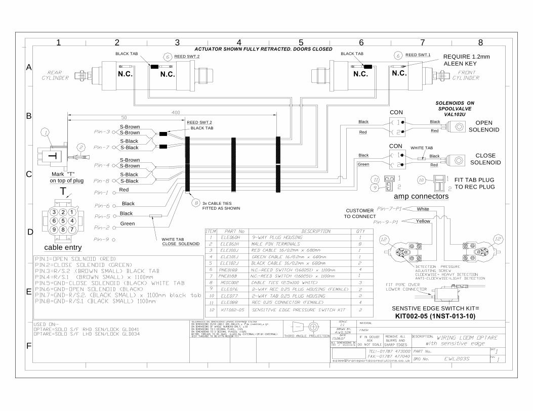
SENSTIVE EDGE SWITCH KIT=KIT002-05 (1NST-013-10)
White
Yellow
CUSTOMERTO CONNECT
B
1 2 3 4 5 6 7 8
A
C
D
E
F
T
REED SWT.1REED SWT.2
3x CABLE TIESFITTED AS SHOWN
S-Brown
S-Black
S-Brown
BLACK TAB
BLACK TABREED SWT.2
WHITE TABCLOSE SOLENOIDGreen
Red
BlackBlack
N.O.N.O.
ACTUATOR SHOWN FULLY RETRACTED. DOORS CLOSED
N.O.N.O.
S-Brown
S-Black
S-BlackS-BrownS-Black
BLACK TAB
cable entry
Mark "T"on top of plug
T
OPENSOLENOID
WHITE TAB
Red
Black
Green
Black
Red
Black
Red
Black
CON
CON
SOLENOIDS ONSPOOLVALVE
VAL102U
CLOSESOLENOID
amp connectors
FIT TAB PLUGTO REC PLUG
SENSTIVE EDGE SWITCH KIT=KIT002-05 (1NST-013-10)
White
Yellow
CUSTOMERTO CONNECT

EXT'L EMERGECYPNEU BUTTON
INT'L PNEU BUTTONS
3
21
(+)(Ov)
CLOSE
4mm BLK
4mm RED
4mm RED
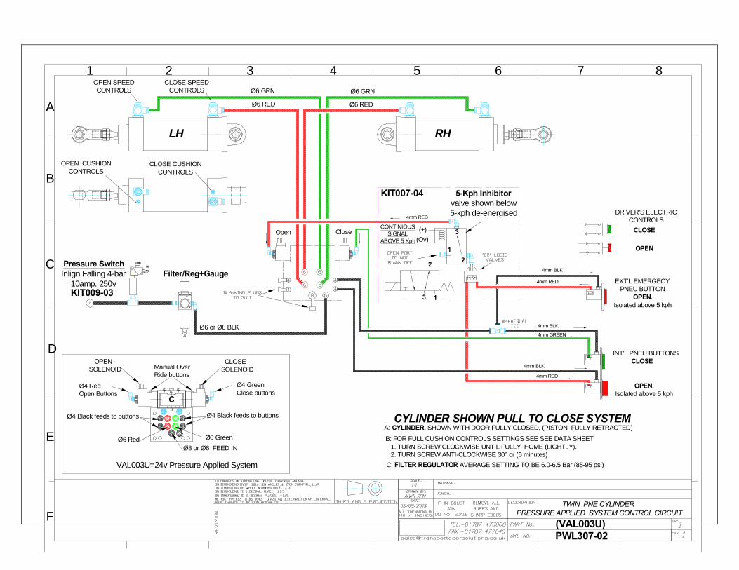
5-Kph Inhibitorvalve shown below5-kph de-energised
Ø6 RED
Ø6 GRNOPEN SPEEDCONTROLS
CLOSE SPEEDCONTROLS
A: CYLINDER, SHOWN WITH DOOR FULLY CLOSED, (PISTON FULLY RETRACTED)CYLINDER SHOWN PULL TO CLOSE SYSTEM
CLOSE CUSHIONCONTROLS
OPEN CUSHIONCONTROLS
B: FOR FULL CUSHION CONTROLS SETTINGS SEE SEE DATA SHEET 1. TURN SCREW CLOCKWISE UNTIL FULLY HOME (LIGHTLY). 2. TURN SCREW ANTI-CLOCKWISE 30° or (5 minutes)
Ø6 RED
Ø6 GRN
21
Filter/Reg+Gauge
Ø6 or Ø8 BLK
Pressure SwitchInlign Falling 4-bar
10amp. 250vKIT009-03
2
3 1
B
1 2 3 4 5 6 7 8
A
C
D
E
FTWIN PNE CYLINDER
AIR BLEED SYSTEM CONTROL CIRCUIT
RHLH
OPEN.Isolated above 5 kph
OPEN.
C: FILTER REGULATOR AVERAGE SETTING TO BE 6.0-6.5 Bar (85-95 psi)
PWL306-02
4mm GREEN
CONTINIOUSSIGNAL
ABOVE 5 Kph
INHIBITORMAY NOT BE FITTED
(VAL102U)
CloseOpen
4mm RED
DRIVER'S ELECTRICCONTROLS
OPEN
CLOSE
Ø4 GreenClose buttons
Ø4 RedOpen Buttons
Ø6 RedØ6 GreenØ8,6,4 FEED IN or OUT
CLOSE -SOLENOID
OPEN -SOLENOID
A
Manual OverRide button
Manual OverRide button
VAL102U=Air Bleed System
NCN0
COM
KIT007-04
3
21
(+)(Ov)
4mm BLK
4mm BLK
4mm BLK
4mm RED
4mm RED
4mm RED
5-Kph Inhibitorvalve shown below5-kph de-energised
CloseOpen
Ø6 RED
Ø6 GRNOPEN SPEEDCONTROLS
CLOSE SPEEDCONTROLS
A: CYLINDER, SHOWN WITH DOOR FULLY CLOSED, (PISTON FULLY RETRACTED)CYLINDER SHOWN PULL TO CLOSE SYSTEM
CLOSE CUSHIONCONTROLS
OPEN CUSHIONCONTROLS
B: FOR FULL CUSHION CONTROLS SETTINGS SEE SEE DATA SHEET 1. TURN SCREW CLOCKWISE UNTIL FULLY HOME (LIGHTLY). 2. TURN SCREW ANTI-CLOCKWISE 30° or (5 minutes)
Ø6 RED
Ø6 GRN
21
Filter/Reg+Gauge
Ø6 or Ø8 BLK
Pressure SwitchInlign Falling 4-bar
10amp. 250vKIT009-03
2
3 1
B
1 2 3 4 5 6 7 8
A
C
D
E
FTWIN PNE CYLINDER
PRESSURE APPLIED SYSTEM CONTROL CIRCUIT
RHLH
C: FILTER REGULATOR AVERAGE SETTING TO BE 6.0-6.5 Bar (85-95 psi)
PWL307-02
Ø4 RedOpen Buttons
Manual OverRide buttons
OPEN -SOLENOID
CLOSE -SOLENOID
Ø4 GreenClose buttons
Ø4 Black feeds to buttonsØ4 Black feeds to buttons
Ø6 Red Ø6 GreenØ8 or Ø6 FEED IN
VAL003U=24v Pressure Applied System
C
CONTINIOUSSIGNAL
ABOVE 5 Kph
(VAL003U)
DRIVER'S ELECTRICCONTROLS
OPEN
CLOSE
EXT'L EMERGECYPNEU BUTTON
INT'L PNEU BUTTONSCLOSE
OPEN.Isolated above 5 kph
OPEN.Isolated above 5 kph
4mm GREEN
NCN0
COM
KIT007-04

3
21
(+)(Ov)
4mm BLK
4mm BLK
4mm BLK
4mm RED
4mm RED
4mm RED
5-Kph Inhibitorvalve shown below5-kph de-energised
CloseOpen
A: CYLINDER, SHOWN WITH DOOR FULLY CLOSED, (PISTON FULLY RETRACTED)CYLINDER SHOWN PULL TO CLOSE SYSTEM
B: FOR FULL CUSHION CONTROLS SETTINGS SEE SEE DATA SHEET 1. TURN SCREW CLOCKWISE UNTIL FULLY HOME (LIGHTLY). 2. TURN SCREW ANTI-CLOCKWISE 30° or (5 minutes)
21
Filter/Reg+Gauge
Ø6 or Ø8 BLK
Pressure SwitchInlign Falling 4-bar
10amp. 250vKIT009-03
2
3 1
RH LH
C: FILTER REGULATOR AVERAGE SETTING TO BE 6.0-6.5 Bar (85-95 psi)
Ø4 RedOpen Buttons
Manual OverRide buttons
OPEN -SOLENOID
CLOSE -SOLENOID
Ø4 GreenClose buttons
Ø4 Black feeds to buttonsØ4 Black feeds to buttons
Ø6 Red Ø6 GreenØ8 or Ø6 FEED IN
VAL003U=24v Pressure Applied System
C
CONTINIOUSSIGNAL
ABOVE 5 Kph DRIVER'S ELECTRICCONTROLS
EXT'L EMERGECYPNEU BUTTON
INT'L PNEU BUTTONS
Isolated above 5 kph
4mm GREEN
NCN0
COM
KIT007-04
SENSADOR ADJUSTING SCREWCLOCKWISE =HARDER DETECTION
ANTI-CLOCKWISE SOFTER DETECTION
D: SENSADOOR SYSTEM PIPED SHOWN DETECTING DOORS ON OPENING CYCLE
CLOSE CUSHIONCONTROLS
OPEN CUSHIONCONTROLS
OPEN SPEEDCONTROLS
CLOSE SPEEDCONTROLS
4mm GREEN
4mm RED
6mm GREEN6mm GREEN
6mm RED 6mm RED
DETECTION ELECTRIC SWITCHWITH DOORS IN THE FULLY CLOSEDPOSITION, SWITCH CONTACTS WILL
BE IN OPEN POSITION
POSITIVE PRESSURE INWITH DOORS FULLY CLOSED
WHEN DOORS ARE OPENING AND DETECTS A OBSTRUCTION ANDWHEN DOORS ARE FULLY OPEN.SWITCH CONTACTS WILL GO TO
CLOSE POSITION SENDINGSIGNALE TO RECLOSE DOORS
OPEN.Isolated above 5 kph
OPEN.
OPEN.
OPEN.
CLOSE
CLOSE
5N DETECTIONVALVE
IMPORTANT:- SENSADOR ON OPENING ONLY
5N DETECTIONVALVE
4mm GREEN
4mm RED
B
1 2 3 4 5 6 7 8
A
C
D
E
FTWIN PNE CYLINDER
PRESSURE APPLIED SYSTEM CONTROL CIRCUIT
PWL307-05(VAL003U)
REV.2 (22-04-2014)DETECTION VALVE CHANGETO ONE TO EACH CYLINDER WAS ONE BETWEEN TWOCYLINDERS
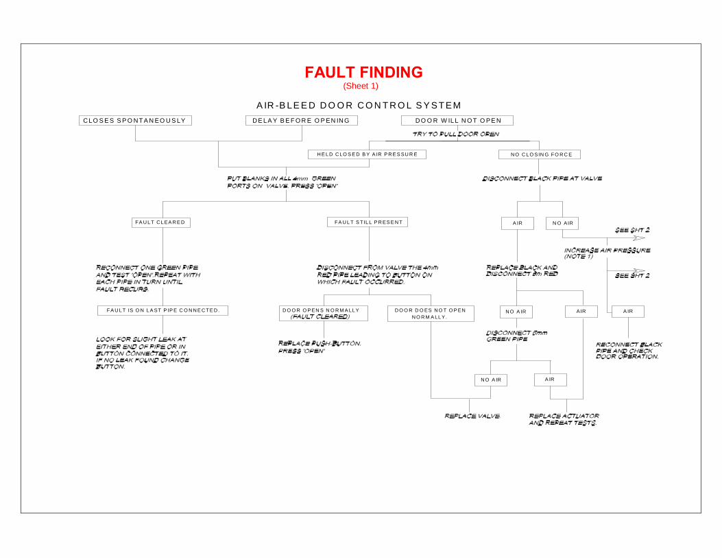
FAULT FINDING (Sheet 1)
N O R M A LL Y.
N O A IR A IR
FA U L T C L EA R E D
FA U L T IS O N L A ST P IP E C O N N E C TE D . D O O R O P EN S N O R M A LL Y D O O R D O ES N O T O P EN N O A IR AIR A IR
FA U L T S T IL L P R ES E N T N O AIRA IR
D E LA Y B E F O R E O P EN IN GC LO S E S S P O N T A N EO U S LY
H E L D C LO S E D B Y A IR P R E S SU R E N O C L O SIN G FO R C E
D O O R W ILL N O T O PE N
A IR -B LE E D D O O R C O N T R O L S Y S T E M
I
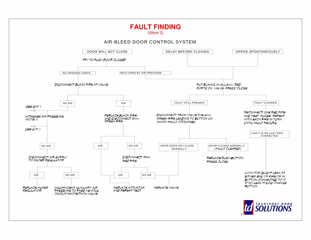
FAULT FINDING (Sheet 2)
AIR-BLEED DOOR CONTROL SYSTEM
OPENS SPONTANEOUSLYDOOR WILL NOT CLOSE DELAY BEFORE CLOSING
NO OPENING FORCE HELD OPEN BY AIR PRESSURE
AIRNO AIR
NO AIR
AIR NO AIR
AIR NO AIR
FAULT CLEAREDFAULT STILL PRESENT
NORMALLY.DOOR CLOSES NORMALLYDOOR DOES NOT CLOSE
FAULT IS ON LAST PIPE
NO AIRAIR
CONNECTED.
I
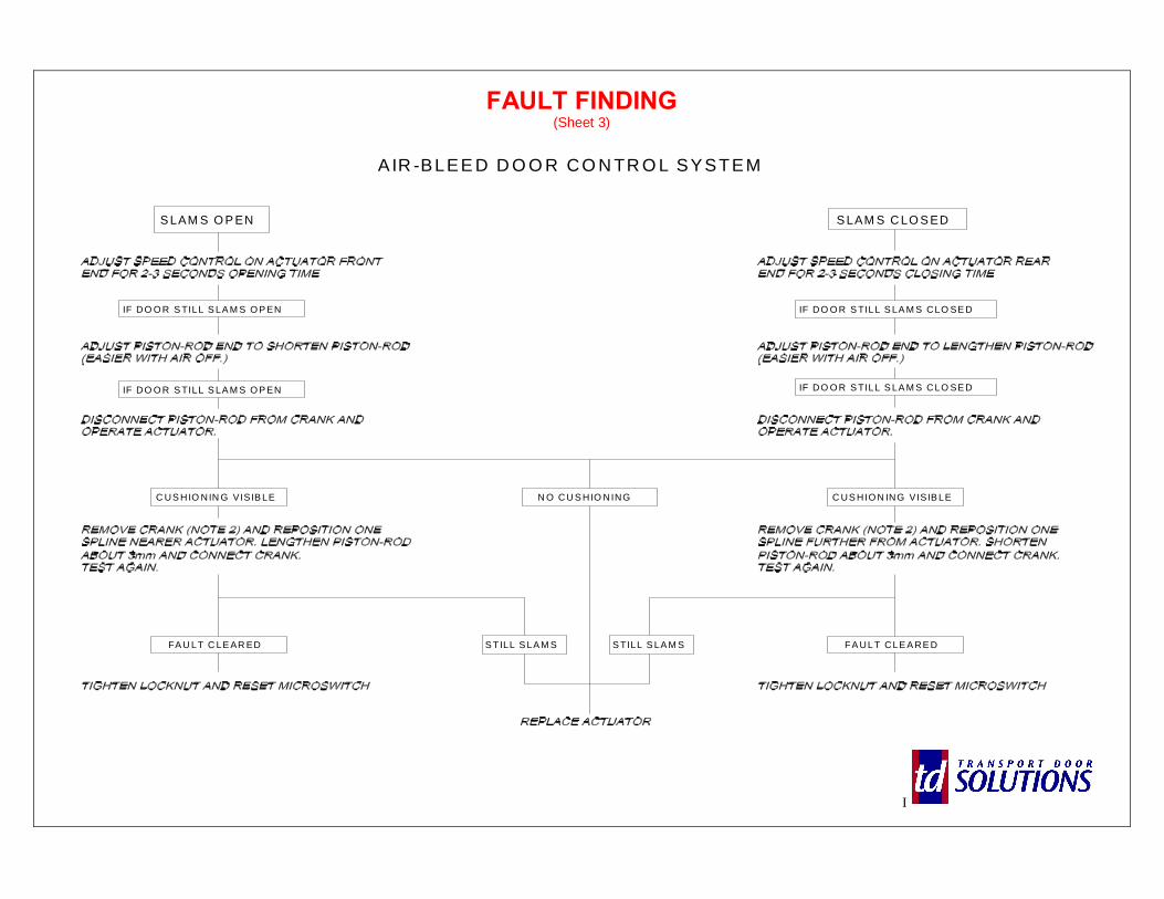
FAULT FINDING (Sheet 3)
AIR -BLEE D D O O R CO N TR O L SYSTEM
S LAM S O P EN
IF DO O R S TILL S LA M S O P EN
IF DO O R S TILL S LA M S O P EN
C US HIO NIN G VISIB LE
FA U LT C LE AR ED FA UL T CLE A RE D
C US HIO N ING VISIB LE
IF DO O R S TILL S LA M S CLO SE D
S LAM S C LO S ED
IF DO O R S TILL S LA M S CLO SE D
N O CU S HIO NING
S TILL S LA M S S TILL S LA M S
I
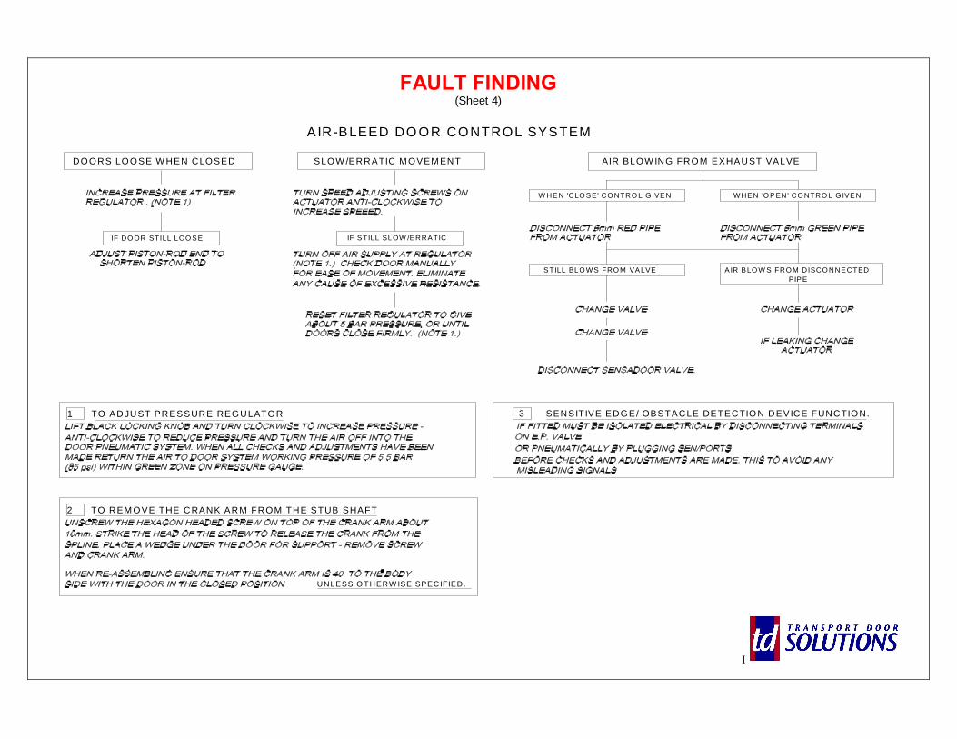
FAULT FINDING (Sheet 4)
A IR-BLEED DO OR CONTROL SYSTEM
DO O RS LO O SE W HEN CLO SED
IF DO OR STILL LOO SE IF STILL SLOW /ERRATIC
SLO W /ERRATIC M O VEM ENT AIR BLO W ING FRO M EXHAUST VALVE
W HEN 'CLO SE' CO NTRO L G IVEN W HEN 'O PEN' CO NTRO L G IVEN
STILL BLO W S FRO M VALVE AIR BLO W S FRO M DISCO NNECTED PIPE
1 TO ADJUST PRESSURE REG ULATO R
2 TO REM O VE THE CRANK ARM FRO M THE STUB SHAFT
3 SENSITIVE EDG E/ OBSTACLE DETECTIO N DEVICE FUNCTIO N.
UNLESS O THERW ISE SPECIFIED.

SHEET FOR NOTES/COMMENTS > (INTENTIONALLY BLANK)
THE IMAGES IN THIS DOCUMENT ARE THE PROPERTY OF TRANSPORT DOOR SOLUTIONS LTD AND MUST NOT BE COPIED OR REPRODUCED WITHOUT WRITTEN PERMISSION
copyright © 2008 Transport Door Solutions Ltd